geotechnical engineering ecg 503 lecture · pdf file · 2011-05-04cantilever wall...
TRANSCRIPT

GEOTECHNICAL ENGINEERING
ECG 503
LECTURE NOTE 07
3.0 ANALYSIS AND DESIGN OF
RETAINING STRUCTURES

LEARNING OUTCOMES
Learning outcomes:
At the end of this lecture/week the students would
be able to:
Understand types of retaining walls

TOPIC TO BE COVERED
Types of Retaining Structures

LATERAL EARTH PRESSURE
Introduction & Overview
2.1 Introduction and overview
Retaining structures such as retaining walls, basement
walls, and bulkheads are commonly encountered in
foundation engineering, and they may support slopes
of earth mass.
Proper design and construction of these structures
require a thorough knowledge of the lateral forces that
act between the retaining structures and the soil mass
being retained.

• Retaining walls are used to prevent the retained material from assuming its natural slope. Wall structures are commonly use to support earth are piles. Retaining walls may be classified according to how they produce stability as reinforced earth, gravity wall, cantilever wall and anchored wall. At present, the reinforced earth structure is the most used particularly for roadwork

3 basic components of reinforced earth wall
• Facing unit – not necessary but usually used to
maintain appearance and avoid soil erosion
between the reinforces.
• Reinforcement – strips or rods of metal, strips
or sheets of geotextiles, wire grids, or chain link
fence or geogrids fastened to the facing unit
and extending into the backfill some distance.
• The earth fill – usually select granular material
with than 15% passing the no. 200 sieve.

Component of E.R. Wall

Types of Retaining Wall
Retaining Wall
Gravity Walls
Embedded walls
Reinforced and anchored earth
The various types of earth-retaining structures
fall into three broad groups.
EARTH RETAINING STRUCTURES

Gravity Walls
Gravity Walls
Masonry walls
Gabion walls
Crib walls
RC walls
Counterfort walls
Buttressed walls
EARTH RETAINING STRUCTURES

Gravity Walls
Unreinforced masonry wall
EARTH RETAINING STRUCTURES
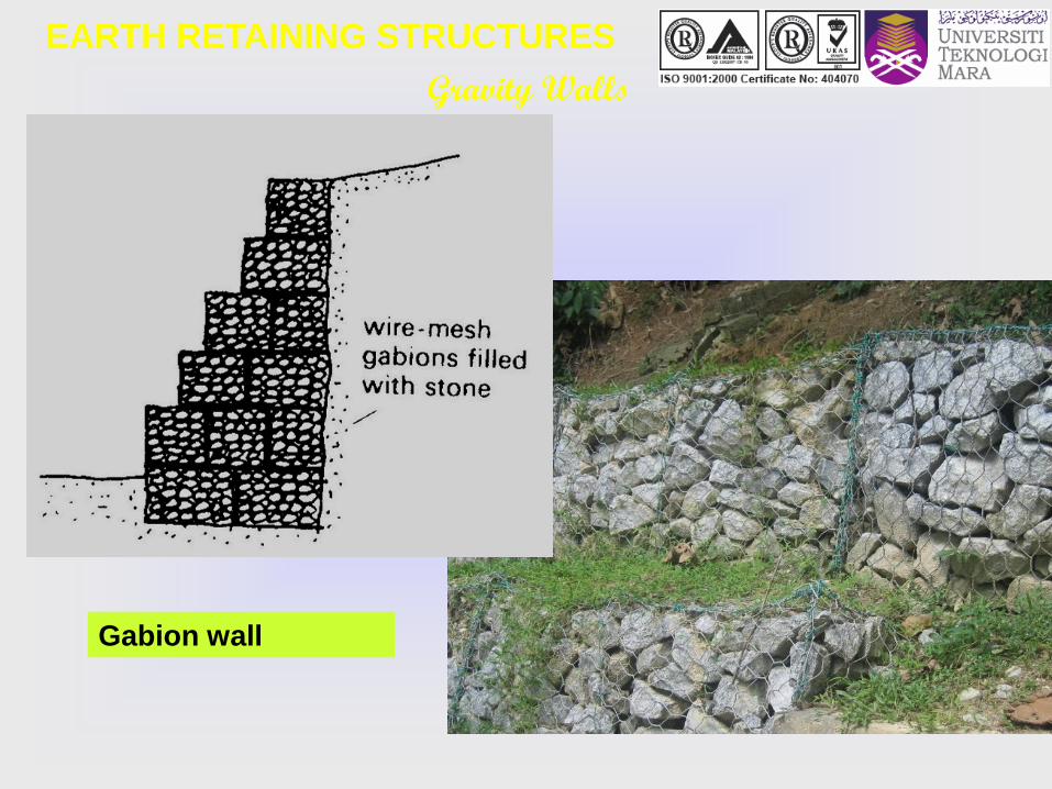
Gravity Walls
Gabion wall
EARTH RETAINING STRUCTURES

Gravity Walls
Crib wall
EARTH RETAINING STRUCTURES

Gravity Walls
Types of RC
Gravity Walls
EARTH RETAINING STRUCTURES

Embedded Walls
Embedded walls
Driven sheet-pile walls
Braced or propped walls
Contiguous bored-pile walls
Secant bored-pile walls
Diaphram walls
EARTH RETAINING STRUCTURES

Embedded Walls
Types of embedded walls
EARTH RETAINING STRUCTURES

Reinforced and Anchored Earth
Reinforced and anchored earth
Reinforced earth wall
Soil nailing
Ground anchors
EARTH RETAINING STRUCTURES

Reinforced and anchored earth
Reinforced earth and soil nailing
EARTH RETAINING STRUCTURES


Stability Criteria
Stability of Rigid Walls
Failures of the rigid gravity wall may occur
due to any of the followings:
Overturning failure
Sliding failure
Bearing capacity failure
Tension failure in joints
Rotational slip failure
In designing the structures at least the first three of the
design criteria must be analysed and satisfied.
EARTH RETAINING STRUCTURES

LATERAL EARTH PRESSURE
Types of Lateral Pressure
Hydrostatic Pressure and Lateral Thrust
Earth Pressure at Rest
Active Earth Pressure
Passive Earth pressure
States of Equilibrium

LATERAL EARTH PRESSURE
Types of Lateral Pressure
Hydrostatic pressure and lateral thrust
Horizontal pressure due to a liquid

LATERAL EARTH PRESSURE
Earth Pressure at Rest
Earth pressure at rest
Earth pressure at rest
z
σv
σh = Ko σv
A
B
If wall AB remains static –
soil mass will be in a state
of elastic equilibrium –
horizontal strain is zero.
Ratio of horizontal stress to
vertical stress is called
coefficient of earth
pressure at rest, Ko, or
v
ho K
z K K ovoh
Unit weight of soil = γ
tan c f

LATERAL EARTH PRESSURE
Earth pressure at rest .. cont.
Earth Pressure at Rest

LATERAL EARTH PRESSURE
Active Earth Pressure
Active earth pressure
Earth pressure at rest
z
σv
σh
A
B
Plastic equilibrium in soil
refers to the condition
where every point in a soil
mass is on the verge of
failure.
If wall AB is allowed to move
away from the soil mass
gradually, horizontal stress
will decrease.
This is represented by
Mohr’s circle in the
subsequent slide.
Unit weight of soil = γ
tan c f

ACTIVE EARTH PRESSURE (RANKINE’S)
(in simple stress field for c=0 soil) – Fig. 1
σX = Ko σz
σz
σzKo σzσx’A
ø


LATERAL EARTH PRESSURE
Based on the diagram :
pressure earthactive sRankine' of tcoefficien Ratiov
a
aK (Ka is the ratio of the effective stresses)
Therefore :
sin 1
sin -1 )
2 (45 -tan K
2
v
aa
It can be shown that :
aa
2
a
K 2c -Kz
)2
(45 - tan 2c -)2
(45 -tanz
Active Earth Pressure

LATERAL EARTH PRESSURE
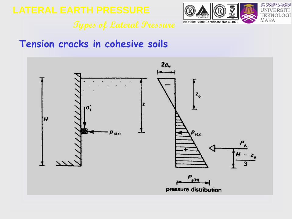
aa K 2c -Kz
z
zo
aK 2c-
Active pressure distribution
Active Earth Pressure
aK 2c-
K z a

LATERAL EARTH PRESSURE
Active pressure distribution
Active Earth Pressure
Based on the previous slide, using
similar triangles show that :
a
oK
cz
2 where zo is depth of tension
crack
For pure cohesive soil, i.e. when = 0 :
czo
2

LATERAL EARTH PRESSURE
For cohesionless
soil, c = 0
aava Kz K
z
Active pressure distribution
Active Earth Pressure
K z a

LATERAL EARTH PRESSURE
Passive Earth Pressure
2.2.4 Passive earth pressure
Earth pressure at rest
z
σv
σh
A
B
If the wall is pushed into the
soil mass, the principal
stress σh will increase. On
the verge of failure the
stress condition on the soil
element can be expressed
by Mohr’s circle b.
The lateral earth pressure,
σp, which is the major
principal stress, is called
Rankine’s passive earth
pressure
Unit weight of soil = γ
tan c f

PASSIVE EARTH PRESSURE (RANKINE’S)
(in simple stress field for c=0 soil) – Fig. 2
σX = Ko σz
σz
σzKo σz σx’P
ø


LATERAL EARTH PRESSURE
Shear
str
ess
Normal stress
tan c f
C
D
D’
OA σpKoσv
b
a
σv
c
Mohr’s circle
representing
Rankine’s
passive state.
Passive Earth Pressure

LATERAL EARTH PRESSURE
For cohesionless soil :
Referring to previous slide, it can be shown that :
Passive Earth Pressure
pp
2
vp
K 2c Kz
)2
(45 tan 2c )2
(45 tan
sin 1
sin 1 )
2 (45 tan K
2
p
v
p

LATERAL EARTH PRESSURE
For cohesionless soil,
Passive pressure distribution
Passive Earth Pressure
z
Kz ppK2c
ppvp Kz K

LATERAL EARTH PRESSURE
In conclusion
Earth Pressure
Wall tilt
Passive pressure
At-rest pressure
Active pressure
Eart
h
Pre
ssu
re
Wall tilt

LATERAL EARTH PRESSURE
Types of Lateral Pressure
Rankine’s Theory
Assumptions :
Vertical frictionless wall
Dry homogeneous soil
Horizontal surface
Initial work done in 1857
Develop based on semi infinite “loose granular” soil
mass for which the soil movement is uniform.
Used stress states of soil mass to determine lateral
pressures on a frictionless wall

LATERAL EARTH PRESSURE
Types of Lateral Pressure
Active pressure for cohesionless soil

LATERAL EARTH PRESSURE
Types of Lateral Pressure
Effect of a stratified soil
Effect of surcharge

LATERAL EARTH PRESSURE
Types of Lateral Pressure
Effect of sloping surface

LATERAL EARTH PRESSURE
Types of Lateral Pressure
Active pressure,
Passive pressure,
cos ''
vahaK
cos ''
vphpK
where)'cos - (cos cos
)'osc - (cos - cos
22
22
aK
a
22
22
p
1
)'cos - (cos cos
)'osc - (cos cos
KK
and
LATERAL EARTH PRESSURE
Types of Lateral Pressure
Tension cracks in cohesive soils

LATERAL EARTH PRESSURE
Types of Lateral Pressure
Effect of surcharge (undrained)

LATERAL EARTH PRESSURE
Types of Lateral Pressure
Passive resistance in undrained clay

LATERAL EARTH PRESSURE
The stability of the retaining wall should be checked against :
(ii) FOS against sliding (recommended FOS = 2.0)
(i) FOS against overturning (recommended FOS = 2.0)
Stability Criteria
moment Disturbing
momentResisting FOS
H
wpV
R
Bc P 0.7) -(0.5 tan RFOS

LATERAL EARTH PRESSURE
Stability Analysis
Pp
Ph
∑ V
A
The stability of the retaining wall should
be checked against :
2.3.1 FOS against overturning
(recommended FOS = 2.0)
moment Disturbing
momentResisting FOS
.. overturning about A

LATERAL EARTH PRESSURE
2.3.2 FOS against sliding
(recommended FOS = 2.0)
Stability Criteria
H
wpV
R
Bc P 0.7) -(0.5 tan RFOS
Ph
∑ V
Pp
Friction & wall base adhesion

LATERAL EARTH PRESSURE
B
6e
B
R q V
b 1
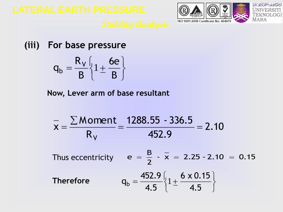
2.3.3 For base pressure (to be compared against the
bearing capacity of the founding soil. Recommended
FOS = 3.0)
Now, Lever arm of base resultant
Thus eccentricity
R
Moment x
V
x - 2
B e
Stability Criteria

LATERAL EARTH PRESSURE
Stability Analysis
Pp
Ph
∑ V
Base pressure on the founding soil

Stability Analysis
LATERAL EARTH PRESSURE
Figure below shows the cross-section of a reinforced concrete
retaining structure. The retained soil behind the structure and
the soil in front of it are cohesionless and has the following
properties:
SOIL 1 : u = 35o, d = 17 kN/m3,
SOIL 2 : u = 30o, = 25o , d = 18 kN/m3,
sat = 20 kN/m3
The unit weight of concrete is 24 kN/m3. Taking into account the
passive resistance in front of the wall, determine a minimum value
for the width of the wall to satisfy the following design criteria:
Factor of safety against overturning > 2.5
Factor of safety against sliding > 1.5
Maximum base pressure should not exceed 150 kPa
Worked example :

Stability Analysis
LATERAL EARTH PRESSURE
SOIL 2
2.0 m
0.5 m
0.6 m
2.9 m
2.0 m
GWT
4.5 m
SOIL 1
SOIL 2
30 kN/m2
4.0 m
THE PROBLEM

LATERAL EARTH PRESSURE
Stability Analysis
P1P3
SOIL 2
2.0 m
0.5 m
0.6 m
2.9 m
2.0 m
GWT
4.5 m
SOIL 1
SOIL 2
30 kN/m2
4.0 m
P2P4
PP
W41
W3
W2
W1
P5
THE SOLUTION
P6

LATERAL EARTH PRESSURE
Stability Analysis
271.035sin1
35sin -1
sin1
sin1o
o
1
aK
333.030sin1
30sin -1
sin1
sin1o
o
2
aK
00.330sin1
30sin 1
sin1
sin1o
o
2
pK
Determination of the Earth Pressure Coefficients

LATERAL EARTH PRESSURE
Stability AnalysisELEM. FORCE (kN/m) TOTAL
L. ARM
(m)
MOMENT
(kNm/m)
HORIZONTAL
Active
P1 0.271 x 30 x 2 16.26 4.5 73.17
P2 0.333 x 30 x 3.5 34.97 1.75 61.20
P3 0.5 x 0.271 x 17 x 2 x 2 9.21 4.17 38.41
P4 0.333 x 17 x 2 x 3.5 39.63 1.75 69.35
P5 0.5 x .333 x (20-9.81) x 3.5 x 3.5 20.78 1.167 24.25
P6 0.5 x 9.81 x 3.5 x 3.5 60.09 1.167 70.13
SUM 180.94 336.50
Passive
Pp 0.5 x 3 x 18 x 1.5 x 1.5 60.75 0.5 30.38
VERTICAL
W1 0.5 x 4.9 x 24 58.8 1.75 102.90
W2 0.6 x 4.5 x 24 64.8 2.25 145.80
W3 2 x 2.5 x 17 + 2.9 x 2.5 x 20 + 30 x 2.5 305 3.25 991.25
W4 0.9 x 1.5 x 18 24.3 0.75 18.23
SUM 452.9 1288.55

LATERAL EARTH PRESSURE
Stability Analysis
OK is it thus 2.5, moment Disturbing
moment Resisting 83.3
50.336
55.1288FOS
To check for stability of the retaining wall
(i) FOS against overturning > 2.5
(ii) FOS against sliding > 1.5
1.5 ..
60.75x 0.5 25tan .
R
P0.5 tan RFOS
o
H
pV
341
94180
9452
Thus it is not OK
LATERAL EARTH PRESSURE
Stability Analysis
B
6e
B
R q V
b 1
2.10 452.9
336.5 - 1288.55
R
Moment x
V
(iii) For base pressure
Now, Lever arm of base resultant
0.15 2.10 - 2.25 x - 2
B e
4.5
0.15 x 6
4.5
452.9 qb 1
Thus eccentricity
Therefore

Stability Analysis
LATERAL EARTH PRESSURE
qb = 120.8 and 80.5 kPa
Since maximum base pressure is less than the bearing pressure of the
soil, the foundation is stable against base pressure failure.
DISTRIBUTION OF BASE PRESSURE
80.5 kPa120.8 kPa
In conclusion the retaining wall is not safe against sliding. To
overcome this the width of the base may be increased or a
key constructed at the toe.
Group assignment NO. 1:
Form a group of 6 members in each group. Your task is to
write up a case study which involve a dam case failure in
Malaysia and a slope failure in Malaysia. Your report shall
consists of the history of each case, as examples;
amount of dam in Malaysia, their purpose, operation, etc.
Make sure your case study are not the same as others
groups. Penalties will be given accordingly for those who
ignore the warnings.
Date of submission : 08 October 2009

Group assignment NO. 2:
Form a group of 6 members in each group. Your task is to
write up a case study which involve a ground
improvement technique. Your shall selected a real project
which will consists of real soil problems and technique to
overcome the problems.
Make sure your case study are not the same as others
groups. Penalties will be given accordingly for those who
ignore the warnings.
Date of submission : 15 October 2009