geotechnical engineering ecg 503 lecture note 02reduced by pumping to a depth of 0.5m. draw a flow...
TRANSCRIPT

GEOTECHNICAL
ENGINEERING
ECG 503
LECTURE NOTE 02

LEARNING OUTCOMES
Learning outcomes:
At the end of this lecture/week the students would
be able to:
Draw flow nets below concrete dams and
through earth dams.
Use the flow nets to determine quantity of
seepage flow.


In water retaining dams, unless the
foundations continue down to impervious
rock, a steady flow of water is set up
under the structure owing to the difference
in head. This may lead to an undesirable
amount of leakage and, with an upward
flow of water on the downstream side,
dangerous quicksand conditions may
occur, with possible subsequent failure of
the dam. This seepage can be studied by
the use of flow nets.
SEEPAGE THROUGH SOIL

HYDRAULIC GRADIENT
• Flow of water will occur if there is
a different height between point A
and B at a distance L
A
B
Lh1
i = h1
L

• The 2-Dimensional seepage refers
to the existing of flow in two-axis
(consider x-y plane)

What is a flow net ?
A flow net is a pictorial representation
of the paths taken by water in passing
through a material. It is made of flow
lines and equipotential lines
Flow lines are lines which represent
the path of flow through a soil.
Equipotential lines represent all
points of constant head.

Flow Nets
• Is a graphical construction equipotentials
and flow lines.
• Flow nets that are very complicated and
needs a greater understanding of a seepage
principles; some possible methods of
solution of technique can be used as :
• Finite Different Method
• Finite Element Method
• Electrical Analogy
• Used of Hydraulic Models

FLOW NETS – Construction Procedure
& Boundary Condition
1. The boundary conditions must be satisfied.
2. Flow lines must intersect equipotential lines
at right angles.
3. The area between flow lines and equipotential
lines must be curvilinear squares. A
curvilinear squares has the property that an
inscribed circle can be drawn to touch each
side of the square and continuous bisection
results, in a limit, in a point

4. The quantity of flow through each flow
channel is constant
5. The head loss between each
consecutive equipotential lines is
constant
6. A flow line cannot intersect another flow
line
7. An equipotential line cannot intersect
another equipotential line

By theoretically, any number of flowlines may be drawn and the greater the numbers, the more accurate should be. However, in practical, not more than five of six flow line isnecessary.

CALCULATE PORE WATER
PRESSURE
hz Nd Ndh Hp = Ndh - hz Uz = Hpw


The quantity of seepage can be determined using the following formula :
) //( 3
lengthmetredaymN
NkHQ
d
f
Where :Q = quantity of seepagek = permeability of the soilNf = number of flow intervals (channels)Nd = number of equipotential drops

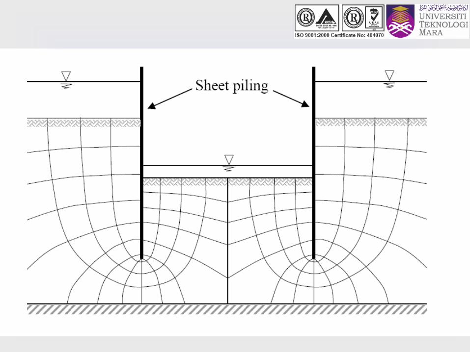
Flow net below a sheet pile

Flow net under a concrete dam
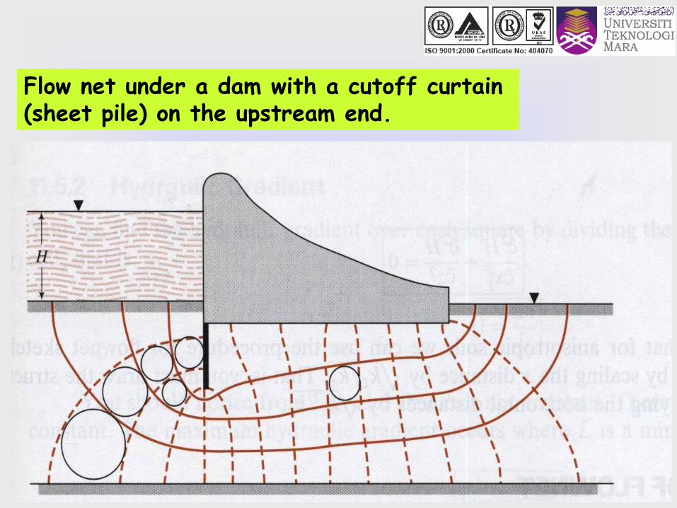
Flow net under a dam with a cutoff curtain (sheet pile) on the upstream end.

WORK EXAMPLES
• Figure 1 shows the cross-section of a line of sheet piling driven to a depth of 7m into a stratum of homogeneous sandy soil which has a thickness of 12m and it is underlain by an impermeable stratum. From an original depth of 5.5m the water level on one side of the piles is reduced by pumping to a depth of 0.5m. Draw a flow net for the seepage condition and from it determine:
a. The quantity of seepage under the piles per
meter run
b. The pore water pressure in the soil at points P and Q
The coefficient of permeability, k = 7.2 x 10⁻³ mm/s


Guidelines of Solving Problem
1. Impermeable boundaries : along the
sheet piling BCD and along the
impermeable stratum GG; therefore
BCD and GG is flow lines
2. Permeable boundaries : along B’B the
pressure head is a constant 5.5m and
along DD’ the pressure head is 0.5m;
B’B and DD’ are therefore is
equipotential of a value of 5.5 and 0.5m
respectively.


A sheet pile was driven to a depth of 5 m into a
stratum of homogeneous sandy soil. The ground
thickness is 12.5 m and is underlain by an
impermeable stratum.For the sandy soil, the
coefficient of permeability, k = 3 x 10⁻⁴ m/s and its
unit weight, γ = 18.5 kN/m3.
a. What is the pressure head if a piezometer is placed at P, Q,
R and S?
b. Determine the total flow discharge in m3/day per metre run
beneath the piles,
c. Tabulate and plot the distribution of water pressure at points
‘a’ – ‘f’ behind the wall.
d. Determine the maximum exit gradient, and hence the factor
of safety against piping in front of the wall.
WORK EXAMPLES

a
b
c
d
e
f
FRONT OF WALL
