geotechnical engineering report - arizona...
TRANSCRIPT


Geotechnical Engineering ReportWest Quartzsite Traffic Interchange ■ Quartzsite, ArizonaMarch 17, 2015 ■ Terracon Project No. 65145257
Responsive ■ Resourceful ■ Reliable
TABLE OF CONTENTS
Page1.0 INTRODUCTION .............................................................................................................12.0 PROJECT INFORMATION .............................................................................................1
2.1 Project Description ...............................................................................................12.2 Site Location and Description...............................................................................2
3.0 SUBSURFACE CONDITIONS ........................................................................................23.1 Site Geology ........................................................................................................23.2 Typical Subsurface Profile ...................................................................................33.3 Laboratory Test Data ...........................................................................................43.4 Percolation Test Results ......................................................................................43.5 Groundwater ........................................................................................................5
4.0 RECOMMENDATIONS FOR DESIGN AND CONSTRUCTION ......................................54.1 Geotechnical Considerations ...............................................................................54.2 Compression Due To Embankment Fill ................................................................64.3 Subgrade Support ................................................................................................64.4 Earthwork Factors and Slopes .............................................................................74.5 General Earthwork ...............................................................................................74.6 Water ...................................................................................................................84.7 Corrosion Potential ..............................................................................................8
5.0 GENERAL COMMENTS .................................................................................................8
EXHIBIT NO.Hough Method of Computing Settlement ............................................................. Exhibit 1
Appendix ASite Plan and Boring Location Diagrams ..................................................................... A-1Field Exploration Description - Borings ........................................................................ A-2General Notes: Drilling & Exploration...................................................................... .....A-3Unified Soil Classification ....................................................................................... .....A-4Boring Logs .................................................................................................. A-5 thru A-15
Appendix BLaboratory Test Description ......................................................................................... B-1Atterberg Limits Results............................................................................................... B-2Grain Size Distribution .................................................................................... B-3 and B-4Moisture-Density Relationship ........................................................................ B-5 thru B-7Consolidation Test Results ............................................................................. B-8 and B-9R-Value Test Results .................................................................................. B-10 and B-11Summary of Laboratory Results ................................................................. B-12 and B-13Summary of Grain Size Distribution ........................................................................... B-14
Responsive ■ Resourceful ■ Reliable 1
GEOTECHNICAL ENGINEERING REPORTWEST QUARTZSITE TRAFFIC INTERCHANGE
QUARTZSITE BOULEVARD AND I-10QUARTZSITE, ARIZONA
Terracon Project No. 65145257March 17, 2015
1.0 INTRODUCTION
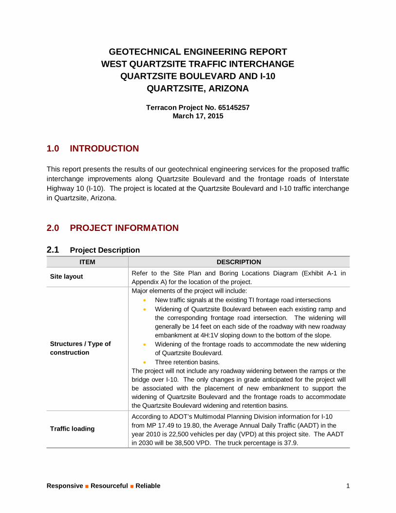
This report presents the results of our geotechnical engineering services for the proposed trafficinterchange improvements along Quartzsite Boulevard and the frontage roads of InterstateHighway 10 (I-10). The project is located at the Quartzsite Boulevard and I-10 traffic interchangein Quartzsite, Arizona.
2.0 PROJECT INFORMATION
2.1 Project DescriptionITEM DESCRIPTION
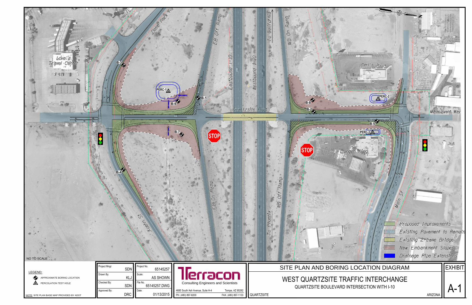
Site layout Refer to the Site Plan and Boring Locations Diagram (Exhibit A-1 inAppendix A) for the location of the project.
Structures / Type ofconstruction
Major elements of the project will include:· New traffic signals at the existing TI frontage road intersections· Widening of Quartzsite Boulevard between each existing ramp and
the corresponding frontage road intersection. The widening willgenerally be 14 feet on each side of the roadway with new roadwayembankment at 4H:1V sloping down to the bottom of the slope.
· Widening of the frontage roads to accommodate the new wideningof Quartzsite Boulevard.
· Three retention basins.The project will not include any roadway widening between the ramps or thebridge over I-10. The only changes in grade anticipated for the project willbe associated with the placement of new embankment to support thewidening of Quartzsite Boulevard and the frontage roads to accommodatethe Quartzsite Boulevard widening and retention basins.
Traffic loading
According to ADOT’s Multimodal Planning Division information for I-10from MP 17.49 to 19.80, the Average Annual Daily Traffic (AADT) in theyear 2010 is 22,500 vehicles per day (VPD) at this project site. The AADTin 2030 will be 38,500 VPD. The truck percentage is 37.9.

Geotechnical Engineering ReportWest Quartzsite Traffic Interchange ■ Quartzsite, ArizonaMarch 17, 2015 ■ Terracon Project No. 65145257
Responsive ■ Resourceful ■ Reliable 2
2.2 Site Location and Description
ITEM DESCRIPTION
Location Quartzsite Boulevard traffic interchange with I-10 in Quartzsite,Arizona.
Existing site features
The existing roadway embankment slopes that support QuartzsiteBoulevard are 28 feet wide south of the eastbound (EB) ramps and42 feet wide north of the westbound (WB) ramps. The existingembankment slopes north of the WB on/off ramps are atapproximately 5H:1V. The existing embankment slopes south ofthe EB on/off ramps are at approximately 3H:1V. There are notraffic signals and no passing lanes within the project limits.There is one proposed corrugated metal pipe extension planned tobe located beneath the EB on ramp and two extensions plannedbeneath the portion of Quartzsite Boulevard that is south of the EBon/off ramps. The pipe extensions are shown on Exhibit A-1.
Existing Pavement Condition
The existing pavement shows slight distress along QuartzsiteBoulevard with higher amount of distress along the frontage roadaround the Love’s Truck Stop site. The distress in Kuehn Streetand Dome Rock Road consisted of alligator cracking.
Surrounding developments
There is a Love’s Truck Stop facility located along the frontageroad on the south side of the traffic interchange. There are twosmall fast foot restaurants along the frontage road on the northside of the traffic interchange.
Existing topography
The topography in the area is relatively flat throughout most of theproject area. The elevation of the project limits is approximately910 feet MSL. The design elevation of Quartzsite Boulevard isnear the original native ground surface grade at the frontage roadsand increases in height above I-10 to the level (elevation) of theon/off ramp intersections. The change in height is approximately15 to 20 feet from the frontage road to the on/off ramp.
3.0 SUBSURFACE CONDITIONS
3.1 Site Geology
The project area is located in the Basin and Range physiographic province (1Cooley, 1967) ofthe North American Cordillera (2Stern, et al, 1979) of the southwestern United States. The
1Cooley, M.E., 1967, Arizona Highway Geologic Map, Arizona Geological Society.
Geotechnical Engineering ReportWest Quartzsite Traffic Interchange ■ Quartzsite, ArizonaMarch 17, 2015 ■ Terracon Project No. 65145257
Responsive ■ Resourceful ■ Reliable 3
southern portion of the Basin and Range province is situated along the southwestern flank ofthe Colorado Plateau and is bounded by the Sierra Nevada Mountains to the west. Formedduring middle and late Tertiary time (100 to 15 m.y. ago), the Basin and Range province isdominated by fault controlled topography. The topography consists of mountain ranges andrelatively flat alluviated valleys. These mountain ranges and valleys have evolved fromgenerally complex movements and associated erosional and depositional processes.Structurally, the site lies within the Phoenix Basin. Drainage flows to the Gila River during lateTertiary time, coupled with structural activity discussed above, are generally responsible for thepresent day topography within the basin.
Surficial geologic conditions mapped at the site (3Wilson, 1960) consist of alluvium of Holoceneto middle Pleistocene age. The alluvial materials have been described as young and weakly tomoderately consolidated deposits consisting of silt, sand, and gravel. Locally, the alluvium caninclude clay deposits.
3.2 Typical Subsurface Profile
Specific conditions encountered at each boring location are indicated on the individual boring logs.Stratification boundaries on the boring logs represent the approximate location of changes in soiltypes; in-situ, the transition between materials may be gradual. Details for each of the borings canbe found on the boring logs included in Appendix A.
As presented on the Logs of Boring, surface soils near the on/off ramp roads consisted of fillmaterials comprised of gravel and/or sand soils with variable amounts of gravel to depths of 18to 19 feet. The thickness of fill materials decreases to about seven feet in the borings at thefrontage roads. The materials underlying the surface fill materials and extending to themaximum depth of exploration consisted of sands and/or gravel soils. The maximum depth ofexploration varied from 2½ feet for the percolation test holes to 50 feet for the borings located atthe higher elevations of Quartzsite Boulevard.
The sand and gravel soils are generally medium dense in relative density throughout the fillzone stratum and to depths of 5 to 10 feet in the native soils beneath the fills. Below themedium dense soils the soils are dense to very dense in relative density.
2Stern, C.W., et al, 1979, Geological Evolution of North America, John Wiley & Sons, Santa Barbara,California.3Wilson, E. D., 1960, Geologic Map of Yuma County, Arizona, Arizona Bureau of Mines, University of Arizona.

Geotechnical Engineering ReportWest Quartzsite Traffic Interchange ■ Quartzsite, ArizonaMarch 17, 2015 ■ Terracon Project No. 65145257
Responsive ■ Resourceful ■ Reliable 4
3.3 Laboratory Test Data
For purposes of pavement thickness design, the results of the laboratory testing, including thecorrelated R-Values and tested R-Values are summarized as shown in the following table:
SUMMARY OF TESTED AND CORRELATED R-VALUESPoint
ID Boring Location Depth(ft.) LL PI -#200 R-Value
TestedR-Value
CorrelatedB-1 EB Off Ramp near Quartzsite Blvd. 1-5 --- NP 12 --- 85B-2 Quartzsite Blvd. just north of WB On Ramp 0-5 --- NP 7 --- 91B-3 Along Dome Rock Rd. west of Quartzsite Blvd. 1-5 --- NP 11 73 86B-4 Along Kuehn St. east of Quartzsite Blvd. 0-4 22 7 13 --- 64B-5 Quartzsite Blvd. near Main St. 0-5 --- NP 10 --- 87
B-6 South of EB off ramp and west of QuartzsiteBlvd. in interior 0-4 --- NP 13 --- 84
B-7 South of EB on ramp and east of QuartzsiteBlvd. in interior 0-4 --- NP 23 77 73
B-8 North of WB on ramp and west of QuartzsiteBlvd. in interior 0-4 21 2 22 --- 68
Count 2 8Average 75 79.6
Standard Deviation 2.83 9.98
3.4 Percolation Test Results
Percolation testing conducted at the location of the proposed retention basins are summarizedas follows:
Percolation Test Results
Test Hole Depth(inches)
SoilClassification
Percolation Rate(minutes/inch)
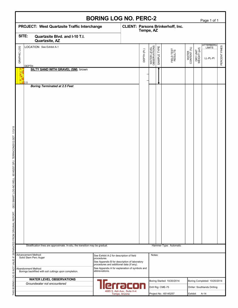
Perc-1 30 SM 16
Perc-2 30 SM 7
Perc-3 30 SM 8
It should be noted that siltation and vegetation growth along with other factors may effect thepercolation rates of the on-site retention basin areas. The actual percolation rate of eachretention area may vary from the values reported here.
Geotechnical Engineering ReportWest Quartzsite Traffic Interchange ■ Quartzsite, ArizonaMarch 17, 2015 ■ Terracon Project No. 65145257
Responsive ■ Resourceful ■ Reliable 5
3.5 Groundwater
Groundwater was not observed in any test boring at the time of the field exploration. Theseobservations represent groundwater conditions at the time of the field exploration and may notbe indicative of other times, or at other locations. Groundwater conditions can change withvarying seasonal and weather conditions, and other factors.
Based on information obtained from the Arizona Department of Water Resources –Groundwater Data website (https://gisweb.azwater.gov/gwsi/Default.aspx), the depth togroundwater was measured in 2009 to be approximately 510 feet below the ground surface(approximate elevation of 430 feet above mean sea level) at an Arizona Department of WaterResources (ADWR) monitored well site located about one-half mile west of the site.
4.0 RECOMMENDATIONS FOR DESIGN AND CONSTRUCTION
4.1 Geotechnical Considerations
Geotechnical engineering recommendations for design and construction of earth connectedphases of the project are outlined below. The recommendations contained in this report arebased upon the results of the test borings performed by Terracon (which are presented inAppendix A) and laboratory testing (which is presented in Appendix B), engineering analyses,and our current understanding of the proposed project.
The geotechnical issues associated with construction of this project will be:
Embankment Settlement: The proposed widening is to be constructed on fillembankments up to 10 feet high. The analyses and results are presented in Section4.2.Subgrade Support: The recommended resilient modulus for use in design ofpavements is presented in Section 4.3.Retention Basin: Three retention basins are planned at the locations of Perc-1, Perc-2and Perc-3. Recommendations for the excavated slopes are presented in Section 4.4.General Earthwork Recommendations: The placement of the embankment materialsshould be comprised of select granular materials and placed in accordance with ADOTrequirements. These recommendations are outlined in Section 4.5.
Prior to placement of embankment fill materials, we recommend the Geotechnical engineeringrecommendations for roadway construction and other earth connected phases of the project areoutlined below.
Geotechnical Engineering ReportWest Quartzsite Traffic Interchange ■ Quartzsite, ArizonaMarch 17, 2015 ■ Terracon Project No. 65145257
Responsive ■ Resourceful ■ Reliable 6
4.2 Compression Due To Embankment Fill
Terracon has analyzed the settlement of the fill materials and native soils due to the pressureincrease from the proposed embankment fill construction proposed for the project. At STA13+00 the fill thickness will be about 10 feet, and appears to be the location with the thickestamount of new fill. This location has been analyzed for settlement as the area representing thehighest proposed stress increase on the project.
The Hough method of computing compression was used to estimate the compression of theexisting soils due to the new embankment fill construction. Groundwater was not encounteredin our exploratory borings as previously discussed. Fluctuation of groundwater which wouldcause a significant change in moisture conditions of the in-situ soils is not expected. Therefore,for purposes of our settlement analyses, all the soil types encountered in the borings weremodeled for elastic settlement. Consolidation settlement due to change in moisture was notconsidered in the analysis.
The subsurface soils and the proposed embankments were analyzed using the Hough method.The input data and output results for the settlement analyses are presented as Exhibit 1 at theend of the text of this report.
The compression of the existing soils at STA 13+00 due to the new embankment fillconstruction is estimated to be on the order of ½ inch.
Compression within the new embankment fill is estimated to be about 1½% of the newembankment height. Thus the estimated compression within the embankment south of the EBon/off ramps will be about 1½ to 2 inches where the new fill is estimated to have a maximumthickness of about 10 feet. The estimated compression within the embankment north of the WBon/off ramps will be about ½ to ¾ inches where the new fill is estimated to have a maximumthickness of about 3 to 4 feet. Based on the granular characteristic of the existing fill materials,on-site soils, compression of the existing soils is anticipated to take place during placement ofthe new fill. We anticipate approximately 80% of the estimated compression of the newembankment fill will occur during construction of the project with the remaining 20% occurringsubsequent to project completion.
4.3 Subgrade Support
The laboratory test data was used to establish one mean R-Value for pavement design withinthe project limits. The data indicates the subgrade soils at the site have excellent supportcharacteristics for the planned pavement sections. The mean R-Value for the project is 76. Thecorresponding resilient modulus is 74,220 pounds per square inch (psi) for a seasonal variationfactor of 0.6. For design of pavements the resilient modulus should be limited to 26,000 psi inaccordance with the ADOT Preliminary Engineering and Design Manual (PE & D manual).
Geotechnical Engineering ReportWest Quartzsite Traffic Interchange ■ Quartzsite, ArizonaMarch 17, 2015 ■ Terracon Project No. 65145257
Responsive ■ Resourceful ■ Reliable 7
The recommended pavement section designs are being prepared by ADOT.
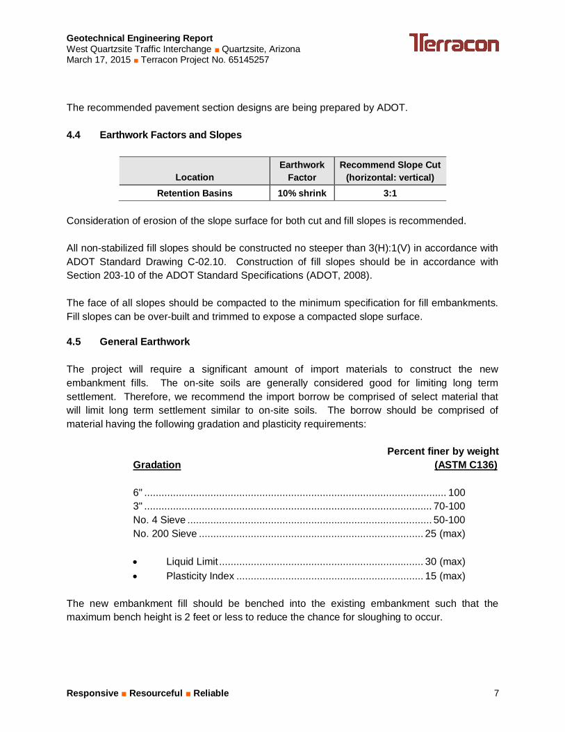
4.4 Earthwork Factors and Slopes
LocationEarthwork
FactorRecommend Slope Cut
(horizontal: vertical)Retention Basins 10% shrink 3:1
Consideration of erosion of the slope surface for both cut and fill slopes is recommended.
All non-stabilized fill slopes should be constructed no steeper than 3(H):1(V) in accordance withADOT Standard Drawing C-02.10. Construction of fill slopes should be in accordance withSection 203-10 of the ADOT Standard Specifications (ADOT, 2008).
The face of all slopes should be compacted to the minimum specification for fill embankments.Fill slopes can be over-built and trimmed to expose a compacted slope surface.
4.5 General Earthwork
The project will require a significant amount of import materials to construct the newembankment fills. The on-site soils are generally considered good for limiting long termsettlement. Therefore, we recommend the import borrow be comprised of select material thatwill limit long term settlement similar to on-site soils. The borrow should be comprised ofmaterial having the following gradation and plasticity requirements:
Percent finer by weightGradation (ASTM C136)
6" ......................................................................................................... 1003" .................................................................................................... 70-100No. 4 Sieve ..................................................................................... 50-100No. 200 Sieve .............................................................................. 25 (max)
· Liquid Limit ....................................................................... 30 (max)· Plasticity Index ................................................................. 15 (max)
The new embankment fill should be benched into the existing embankment such that themaximum bench height is 2 feet or less to reduce the chance for sloughing to occur.

Geotechnical Engineering ReportWest Quartzsite Traffic Interchange ■ Quartzsite, ArizonaMarch 17, 2015 ■ Terracon Project No. 65145257
Responsive ■ Resourceful ■ Reliable 8
4.6 Water
For balancing grading plans, approximately 90 gallons of water per cubic yard should beestimated for compaction of embankment fill and aggregate base materials. Approximately 70gallons of water per cubic yard should be estimated for compaction of subgrade materials.
The application of water estimated for subgrade materials is considerably higher than theamount calculated based upon the difference between in-situ and optimum compaction moisturecontent, and includes a conservative overrun for losses due to seepage, evaporation,inadequate mixing, spillage, etc. Precipitation during and/or before construction, or otherweather conditions may reduce the required amount of water.
4.7 Corrosion Potential
Considering the only on-site soils that may be used for new embankment fill will come from thethree proposed retention basins, we performed corrosivity laboratory testing on samplesobtained from the borings located at the proposed retention basins. Laboratory testing indicatesthat the pH varied from 6.8 to 7.5, and the minimum resistivity varied from 590 ohm-cm to 670ohm-cm. Laboratory testing indicates that the soluble chloride contents varied from 390 ppm to450 ppm, and the soluble sulfate contents varied from 54 ppm to 890 ppm. Based on thesoluble sulfate test results, ASTM Type I/II portland cement is considered suitable for allconcrete on and below grade. The results of the lab testing are summarized in the followingtable:
Summary of Chemical Laboratory Testing
Boring Depth (feet) pHMinimum
Resistivity(ohm-cm)
Chloride(ppm)
Sulfate(ppm)
B-6 0.0 - 4.0 6.8 630 390 130
B-7 0.0 - 4.0 7.5 670 440 54
B-8 0.0 - 4.0 7.2 590 450 890
5.0 GENERAL COMMENTS
Terracon should be retained to review the final design plans and specifications so commentscan be made regarding interpretation and implementation of our geotechnical recommendationsin the design and specifications. Terracon also should be retained to provide observation andtesting services during grading, excavation, pavement construction and other earth-relatedconstruction phases of the project.
Geotechnical Engineering ReportWest Quartzsite Traffic Interchange ■ Quartzsite, ArizonaMarch 17, 2015 ■ Terracon Project No. 65145257
Responsive ■ Resourceful ■ Reliable 9
The analysis and recommendations presented in this report are based upon the data obtainedfrom the borings performed at the indicated locations and from other information discussed inthis report. This report does not reflect variations that may occur between borings, across thesite, or due to the modifying effects of construction or weather. The nature and extent of suchvariations may not become evident until during or after construction. If variations appear, weshould be immediately notified so that further evaluation and supplemental recommendationscan be provided.
The scope of services for this project does not include either specifically or by implication anyenvironmental or biological (e.g., mold, fungi, bacteria) assessment of the site or identification orprevention of pollutants, hazardous materials or conditions. If the owner is concerned about thepotential for such contamination or pollution, other studies should be undertaken.
This report has been prepared for the exclusive use of our client for specific application to theproject discussed and has been prepared in accordance with generally accepted geotechnicalengineering practices. No warranties, either express or implied, are intended or made. Sitesafety, excavation support, and dewatering requirements are the responsibility of others. In theevent that changes in the nature, design, or location of the project as outlined in this report areplanned, the conclusions and recommendations contained in this report shall not be consideredvalid unless Terracon reviews the changes and either verifies or modifies the conclusions of thisreport in writing.

510
Top ofStratum
(ft)
Bottom ofStratum (ft)
MoistDensity
(pcf)
SaturatedDensity
(pcf)
Average N-Value forStratum
Change inStress atCenter(psf)
Center ofStratum (ft)
BuoyantDensity
(pcf)
EffectiveStress atCenter(pcf)
EffectiveStress atBottom
(pcf)
TotalStress atCenter(pcf)
TotalStress atBottom
(pcf)0 13 125 130 22 813 6.5 67.6 813 1625 813 162513 17 125 130 37 475 15.0 67.6 1875 2125 1875 212517 24 120 130 12 350 20.5 67.6 2545 2965 2545 296524 28 120 130 25 288 26 67.6 3205 3445 3205 344528 33 125 130 37 250 30.5 67.6 3758 4070 3758 407033 43 125 130 54 225 38 67.6 4695 5320 4695 532043 56 125 130 73 175 49.5 67.6 6133 6945 6133 6945
Top ofStratum
(ft)
Bottom ofStratum (ft)
CorrectedN-Values C' svo' Dsv'
Settlement(in) Cec
0 13 35 151 813 813 0.31 0.007 This spreadsheet is based on a method presented by Hough, which13 17 39 170 1875 475 0.03 0.006 was later modified by Cheney and Chassie.17 24 11 62 2545 350 0.08 0.01624 28 20 88 3205 288 0.02 0.011 This method is applicable only for normally consolidated cohesionless soils.28 33 28 116 3758 250 0.01 0.00933 43 36 155 4695 225 0.02 0.006 N-values are corrected based on the method proposed by Liao & Whitman.43 56 43 192 6133 175 0.01 0.005
Please see FHWA-IF-02-054 "Shallow Foundations" for more info.
0.47
NOTESWater Level (ft)
Select a Soil Type for each Layer
Total Settlement for Profile (in) =
NOTES:
West Quartzsite Traffic Interchange65145257Borings B-1 & B-2
HOUGH METHOD OF COMPUTING COMPRESSION JOB NAMEJOB NUMBER
USE CORRECTED N VALUES?
TRACS No. 010 LA 017 H8517 01CTerracon Consultants, Inc. EXHIBIT 1
Geotechnical Engineering ReportWest Quartzsite Traffic Interchange ■ Quartzsite, ArizonaMarch 17, 2015 ■ Terracon Project No. 65145257
Responsive ■ Resourceful ■ Reliable
APPENDIX AFIELD EXPLORATION
NOTE: SITE PLAN BASE MAP PROVIDED BY ADOT
Project No.
Scale:
Date:
File No.
SITE PLAN AND BORING LOCATION DIAGRAM
WEST QUARTZSITE TRAFFIC INTERCHANGE
DRC
SDN
KLJ
SDN
01/13/2015
65145257.DWG
AS SHOWN
65145257
A-1
Project Mngr:
Approved By:
Checked By:
Drawn By:
QUARTZSITE ARIZONA
QUARTZSITE BOULEVARD INTERSECTION WITH I-10Consulting Engineers and Scientists
4685 South Ash Avenue, Suite H-4 Tempe, AZ 85282FAX. (480) 897-1133PH. (480) 897-8200
EXHIBITNO TO SCALE
LEGEND:
APPROXIMATE BORING LOCATION
PERCOLATION TEST HOLE
B-3
PERC-1
B-4
B-6
B-7
B-1
B-8
B-2
B-5
PERC-2
PERC-3

Geotechnical Engineering ReportWest Quartzsite Traffic Interchange ■ Quartzsite, ArizonaMarch 17, 2015 ■ Terracon Project No. 65145257
Responsive ■ Resourceful ■ Reliable Exhibit A-2
Field Exploration Description
The field exploration was performed on October 20 and 21, 2014. The borings were drilled todepths of approximately 2½ to 50 feet below existing grade at the approximate locations shownon the attached Site Plan and Boring Locations diagrams, Exhibit A-1 in Appendix A.
The test borings were advanced with a truck-mounted CME-75 drill rig utilizing 4½-inch insidediameter hollow-stem augers. The borings were located in the field by using an aerialphotograph of the site, and measuring from existing physiographic features with a wheel tape.The accuracy of boring locations should only be assumed to the level implied by the methodused.
Lithologic logs of each boring were recorded by the field geologist during the drilling operations.At selected intervals, samples of the subsurface materials were taken by driving split-spoon orring-barrel samplers. Bulk samples of subsurface materials were also obtained. Logs wereprepared for each test boring and are presented in this appendix.
Penetration resistance measurements were obtained by driving the split-spoon and ring-barrelsamplers into the subsurface materials with a 140-pound automatic hammer falling 30 inches.The penetration resistance value is a useful index in estimating the consistency or relativedensity of materials encountered.
A CME automatic SPT hammer was used to advance the split-barrel sampler in the boringsperformed on this site. A greater efficiency is typically achieved with the automatic hammercompared to the conventional safety hammer operated with a cathead and rope. Publishedcorrelations between the SPT values and soil properties are based on the lower efficiencycathead and rope method. This higher efficiency affects the standard penetration resistanceblow count (N) value by increasing the penetration per hammer blow over what would beobtained using the cathead and rope method.
Groundwater conditions were evaluated in each boring at the time of site exploration, andimmediately upon completion of drilling.

Water levels indicated on the soil boringlogs are the levels measured in theborehole at the times indicated.Groundwater level variations will occurover time. In low permeability soils,accurate determination of groundwaterlevels is not possible with short termwater level observations.
NoRecovery
ModifiedDames & MooreRing Sampler
GrabSample
ModifiedCalifornia
Ring Sampler
GENERAL NOTES
4 - 8
Unconfined CompressiveStrength, Qu, psf
ST
RE
NG
TH
TE
RM
S
Over 12 in. (300 mm)12 in. to 3 in. (300mm to 75mm)3 in. to #4 sieve (75mm to 4.75 mm)#4 to #200 sieve (4.75mm to 0.075mmPassing #200 sieve (0.075mm)
Particle Size
RELATIVE DENSITY OF COARSE-GRAINED SOILS
< 55 - 12> 12
Percent ofDry Weight
Descriptive Term(s)of other constituents
RELATIVE PROPORTIONS OF FINES
01 - 1011 - 30
> 30
Plasticity Index
SA
MP
LIN
G
LOCATION AND ELEVATION NOTES
> 99 4,000 to 8,000
2,000 to 4,000
MacroCore
1,000 to 2,000
500 to 1,000
less than 500
Stiff59 - 98
19 - 5810 - 29
Soft7 - 18
Very Soft0 - 60 - 3Very Loose
Hard
(More than 50% retained on No. 200 sieve.)Density determined by Standard Penetration Resistance
Includes gravels, sands and silts.
Percent ofDry Weight
Major Componentof Sample
Water Level After aSpecified Period of Time
Water InitiallyEncountered
Descriptive Term(s)of other constituents
< 1515 - 29> 30
Term
PLASTICITY DESCRIPTION
8 - 15
RockCore
Split SpoonShelby Tube
WA
TE
R L
EV
EL
30 - 50
5 - 9Medium-Stiff
3 - 42 - 44 - 9
< 30 - 1
Very Dense
Dense
Medium Dense
Ring SamplerBlows/Ft.
Ring SamplerBlows/Ft.
Standard Penetration orN-Value
Blows/Ft.
Very Stiff
Loose
Descriptive Term(Consistency)
Standard Penetration orN-Value
Blows/Ft.
TraceWithModifier
RELATIVE PROPORTIONS OF SAND AND GRAVEL GRAIN SIZE TERMINOLOGY
Water Level Aftera Specified Period of Time
TraceWithModifier
Bulk
Soil classification is based on the Unified Soil Classification System. Coarse Grained Soils have more than 50% of their dryweight retained on a #200 sieve; their principal descriptors are: boulders, cobbles, gravel or sand. Fine Grained Soils haveless than 50% of their dry weight retained on a #200 sieve; they are principally described as clays if they are plastic, andsilts if they are slightly plastic or non-plastic. Major constituents may be added as modifiers and minor constituents may beadded according to the relative proportions based on grain size. In addition to gradation, coarse-grained soils are definedon the basis of their in-place relative density and fine-grained soils on the basis of their consistency.
Unless otherwise noted, Latitude and Longitude are approximately determined using a hand-held GPS device. The accuracyof such devices is variable. Surface elevation data annotated with +/- indicates that no actual topographical survey wasconducted to confirm the surface elevation. Instead, the surface elevation was approximately determined from topographicmaps of the area.
> 8,000
DESCRIPTIVE SOIL CLASSIFICATION
(50% or more passing the No. 200 sieve.)Consistency determined by laboratory shear strength testing, field
visual-manual procedures or standard penetration resistance
(HP)
(T)
(b/f)
N
(PID)
(OVA)
Hand Penetrometer
Torvane
Standard PenetrationTest (blows per foot)
N value
Photo-Ionization Detector
Organic Vapor Analyzer
CONSISTENCY OF FINE-GRAINED SOILS
_
> 42> 30
19 - 4215 - 30> 50
10 - 18
BouldersCobblesGravelSandSilt or Clay
Non-plasticLowMediumHigh
Descriptive Term(Density)
DESCRIPTION OF SYMBOLS AND ABBREVIATIONS
FIE
LD
TE
ST
S

UNIFIED SOIL CLASSIFICATION SYSTEM
Criteria for Assigning Group Symbols and Group Names Using Laboratory Tests A Soil Classification
Group Symbol Group Name B
Coarse Grained Soils: More than 50% retained on No. 200 sieve
Gravels: More than 50% of coarse fraction retained on No. 4 sieve
Clean Gravels: Less than 5% fines C
Cu 4 and 1 Cc 3 E GW Well-graded gravel F Cu 4 and/or 1 Cc 3 E GP Poorly graded gravel F
Gravels with Fines: More than 12% fines C
Fines classify as ML or MH GM Silty gravel F,G,H Fines classify as CL or CH GC Clayey gravel F,G,H
Sands: 50% or more of coarse fraction passes No. 4 sieve
Clean Sands: Less than 5% fines D
Cu 6 and 1 Cc 3 E SW Well-graded sand I Cu 6 and/or 1 Cc 3 E SP Poorly graded sand I
Sands with Fines: More than 12% fines D
Fines classify as ML or MH SM Silty sand G,H,I Fines classify as CL or CH SC Clayey sand G,H,I
Fine-Grained Soils: 50% or more passes the No. 200 sieve
Silts and Clays: Liquid limit less than 50
Inorganic: PI 7 and plots on or above “A” line J CL Lean clay K,L,M PI 4 or plots below “A” line J ML Silt K,L,M
Organic: Liquid limit - oven dried
0.75 OL Organic clay K,L,M,N
Liquid limit - not dried Organic silt K,L,M,O
Silts and Clays: Liquid limit 50 or more
Inorganic: PI plots on or above “A” line CH Fat clay K,L,M PI plots below “A” line MH Elastic Silt K,L,M
Organic: Liquid limit - oven dried
0.75 OH Organic clay K,L,M,P
Liquid limit - not dried Organic silt K,L,M,Q Highly organic soils: Primarily organic matter, dark in color, and organic odor PT Peat
A Based on the material passing the 3-inch (75-mm) sieve B If field sample contained cobbles or boulders, or both, add “with cobbles
or boulders, or both” to group name. C Gravels with 5 to 12% fines require dual symbols: GW-GM well-graded
gravel with silt, GW-GC well-graded gravel with clay, GP-GM poorly graded gravel with silt, GP-GC poorly graded gravel with clay.
D Sands with 5 to 12% fines require dual symbols: SW-SM well-graded sand with silt, SW-SC well-graded sand with clay, SP-SM poorly graded sand with silt, SP-SC poorly graded sand with clay
E Cu = D60/D10 Cc = 6010
2
30
DxD
)(D
F If soil contains 15% sand, add “with sand” to group name. G If fines classify as CL-ML, use dual symbol GC-GM, or SC-SM.
H If fines are organic, add “with organic fines” to group name. I If soil contains 15% gravel, add “with gravel” to group name. J If Atterberg limits plot in shaded area, soil is a CL-ML, silty clay. K If soil contains 15 to 29% plus No. 200, add “with sand” or “with gravel,”
whichever is predominant. L If soil contains 30% plus No. 200 predominantly sand, add “sandy” to
group name. M If soil contains 30% plus No. 200, predominantly gravel, add
“gravelly” to group name. N PI 4 and plots on or above “A” line. O PI 4 or plots below “A” line. P PI plots on or above “A” line. Q PI plots below “A” line.

5.0
19.0
FILL - SILTY SAND WITH GRAVEL (SM), brown, medium dense
FILL - SILTY CLAYEY SAND WITH GRAVEL (SC-SM), brown, mediumdense
medium dense to dense
SILTY SAND WITH GRAVEL (SM), brown, loose to medium dense
medium dense
22-28/4"
15-31
22-28/3"
8-12
23-27/5"
12
3
3
4
2
1
127
123
125
114
120
NP
Hammer Type: AutomaticStratification lines are approximate. In-situ, the transition may be gradual.
LOCATION
DEPTH
GR
AP
HIC
LO
G See Exhibit A-1
TH
IS B
OR
ING
LO
G IS
NO
T V
ALI
D IF
SE
PA
RA
TE
D F
RO
M O
RIG
INA
L R
EP
OR
T.
G
EO
SM
AR
T L
OG
-NO
WE
LL 6
514
525
7.G
PJ
TE
RR
AC
ON
2012
.GD
T
1/13
/15
SITE:
Page 1 of 2
Advancement Method:Hollow Stem Auger
Abandonment Method:Borings backfilled with soil cuttings upon completion.
4685 S. Ash Ave., Suite H-4Tempe, Arizona
Notes:
Project No.: 65145257
Drill Rig: CME-75
Boring Started: 10/20/2014
BORING LOG NO. B-1Parsons Brinkerhoff, Inc.CLIENT:Tempe, AZ
Driller: Southlands Drilling
Boring Completed: 10/20/2014
Exhibit: A-5
See Exhibit A-2 for description of fieldproceduresSee Appendix B for description of laboratoryprocedures and additional data (if any).
See Appendix A for explanation of symbols andabbreviations.
Quartzsite Blvd. and I-10 T.I. Quartzsite, AZ
PROJECT: West Quartzsite Traffic Interchange
FIE
LD T
ES
TR
ES
ULT
S
PE
RC
EN
T F
INE
S
WA
TE
RC
ON
TE
NT
(%
)
DR
Y U
NIT
WE
IGH
T (
pcf)
ATTERBERGLIMITS
LL-PL-PI
SA
MP
LE T
YP
E
WA
TE
R L
EV
EL
OB
SE
RV
AT
ION
S
DE
PT
H (
Ft.)
5
10
15
20
25
Groundwater not encounteredWATER LEVEL OBSERVATIONS

32.0
38.0
50.0
SILTY SAND WITH GRAVEL (SM), brown, loose to medium dense(continued)medium dense to dense, weak cementation
CLAYEY SAND WITH GRAVEL (SC), brown to light brown, very dense,weak to moderate cementation
POORLY GRADED GRAVEL WITH SILT AND SAND (SP-SM), brown,very dense, no to weak cementation
Boring Terminated at 50 Feet
25-25/3"
11-39-50/4"
39-39-50/5"
50/6"
34-50/4"
2 122
Hammer Type: AutomaticStratification lines are approximate. In-situ, the transition may be gradual.
LOCATION
DEPTH
GR
AP
HIC
LO
G See Exhibit A-1
TH
IS B
OR
ING
LO
G IS
NO
T V
ALI
D IF
SE
PA
RA
TE
D F
RO
M O
RIG
INA
L R
EP
OR
T.
G
EO
SM
AR
T L
OG
-NO
WE
LL 6
514
525
7.G
PJ
TE
RR
AC
ON
2012
.GD
T
1/13
/15
SITE:
Page 2 of 2
Advancement Method:Hollow Stem Auger
Abandonment Method:Borings backfilled with soil cuttings upon completion.
4685 S. Ash Ave., Suite H-4Tempe, Arizona
Notes:
Project No.: 65145257
Drill Rig: CME-75
Boring Started: 10/20/2014
BORING LOG NO. B-1Parsons Brinkerhoff, Inc.CLIENT:Tempe, AZ
Driller: Southlands Drilling
Boring Completed: 10/20/2014
Exhibit: A-5
See Exhibit A-2 for description of fieldproceduresSee Appendix B for description of laboratoryprocedures and additional data (if any).
See Appendix A for explanation of symbols andabbreviations.
Quartzsite Blvd. and I-10 T.I. Quartzsite, AZ
PROJECT: West Quartzsite Traffic Interchange
FIE
LD T
ES
TR
ES
ULT
S
PE
RC
EN
T F
INE
S
WA
TE
RC
ON
TE
NT
(%
)
DR
Y U
NIT
WE
IGH
T (
pcf)
ATTERBERGLIMITS
LL-PL-PI
SA
MP
LE T
YP
E
WA
TE
R L
EV
EL
OB
SE
RV
AT
ION
S
DE
PT
H (
Ft.)
30
35
40
45
50
Groundwater not encounteredWATER LEVEL OBSERVATIONS
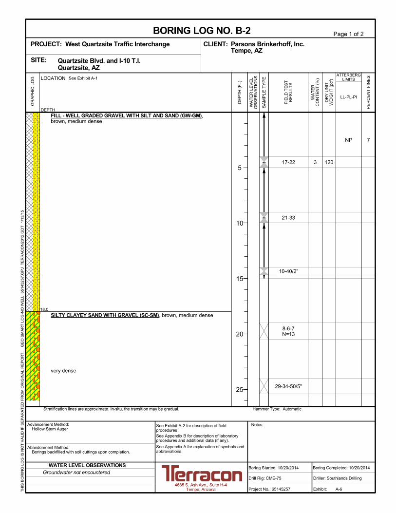
18.0
FILL - WELL GRADED GRAVEL WITH SILT AND SAND (GW-GM),brown, medium dense
SILTY CLAYEY SAND WITH GRAVEL (SC-SM), brown, medium dense
very dense
17-22
21-33
10-40/2"
8-6-7N=13
29-34-50/5"
7
3 120
NP
Hammer Type: AutomaticStratification lines are approximate. In-situ, the transition may be gradual.
LOCATION
DEPTH
GR
AP
HIC
LO
G See Exhibit A-1
TH
IS B
OR
ING
LO
G IS
NO
T V
ALI
D IF
SE
PA
RA
TE
D F
RO
M O
RIG
INA
L R
EP
OR
T.
G
EO
SM
AR
T L
OG
-NO
WE
LL 6
514
525
7.G
PJ
TE
RR
AC
ON
2012
.GD
T
1/13
/15
SITE:
Page 1 of 2
Advancement Method:Hollow Stem Auger
Abandonment Method:Borings backfilled with soil cuttings upon completion.
4685 S. Ash Ave., Suite H-4Tempe, Arizona
Notes:
Project No.: 65145257
Drill Rig: CME-75
Boring Started: 10/20/2014
BORING LOG NO. B-2Parsons Brinkerhoff, Inc.CLIENT:Tempe, AZ
Driller: Southlands Drilling
Boring Completed: 10/20/2014
Exhibit: A-6
See Exhibit A-2 for description of fieldproceduresSee Appendix B for description of laboratoryprocedures and additional data (if any).
See Appendix A for explanation of symbols andabbreviations.
Quartzsite Blvd. and I-10 T.I. Quartzsite, AZ
PROJECT: West Quartzsite Traffic Interchange
FIE
LD T
ES
TR
ES
ULT
S
PE
RC
EN
T F
INE
S
WA
TE
RC
ON
TE
NT
(%
)
DR
Y U
NIT
WE
IGH
T (
pcf)
ATTERBERGLIMITS
LL-PL-PI
SA
MP
LE T
YP
E
WA
TE
R L
EV
EL
OB
SE
RV
AT
ION
S
DE
PT
H (
Ft.)
5
10
15
20
25
Groundwater not encounteredWATER LEVEL OBSERVATIONS
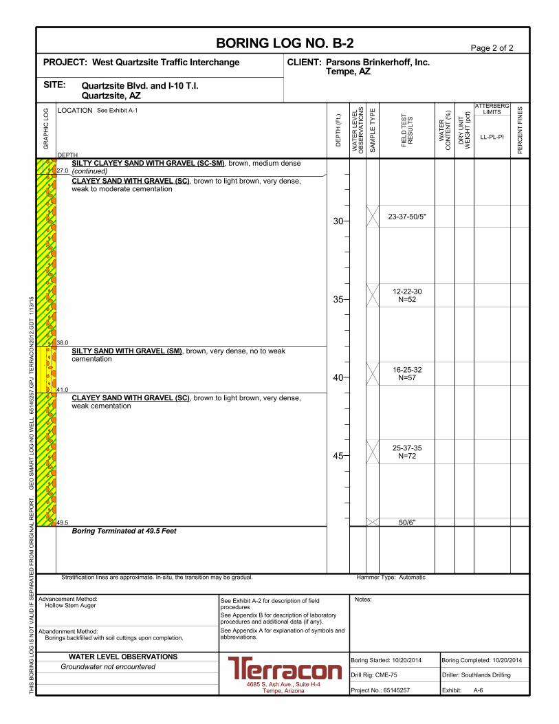
27.0
38.0
41.0
49.5
SILTY CLAYEY SAND WITH GRAVEL (SC-SM), brown, medium dense(continued)CLAYEY SAND WITH GRAVEL (SC), brown to light brown, very dense,weak to moderate cementation
SILTY SAND WITH GRAVEL (SM), brown, very dense, no to weakcementation
CLAYEY SAND WITH GRAVEL (SC), brown to light brown, very dense,weak cementation
Boring Terminated at 49.5 Feet
23-37-50/5"
12-22-30N=52
16-25-32N=57
25-37-35N=72
50/6"
Hammer Type: AutomaticStratification lines are approximate. In-situ, the transition may be gradual.
LOCATION
DEPTH
GR
AP
HIC
LO
G See Exhibit A-1
TH
IS B
OR
ING
LO
G IS
NO
T V
ALI
D IF
SE
PA
RA
TE
D F
RO
M O
RIG
INA
L R
EP
OR
T.
G
EO
SM
AR
T L
OG
-NO
WE
LL 6
514
525
7.G
PJ
TE
RR
AC
ON
2012
.GD
T
1/13
/15
SITE:
Page 2 of 2
Advancement Method:Hollow Stem Auger
Abandonment Method:Borings backfilled with soil cuttings upon completion.
4685 S. Ash Ave., Suite H-4Tempe, Arizona
Notes:
Project No.: 65145257
Drill Rig: CME-75
Boring Started: 10/20/2014
BORING LOG NO. B-2Parsons Brinkerhoff, Inc.CLIENT:Tempe, AZ
Driller: Southlands Drilling
Boring Completed: 10/20/2014
Exhibit: A-6
See Exhibit A-2 for description of fieldproceduresSee Appendix B for description of laboratoryprocedures and additional data (if any).
See Appendix A for explanation of symbols andabbreviations.
Quartzsite Blvd. and I-10 T.I. Quartzsite, AZ
PROJECT: West Quartzsite Traffic Interchange
FIE
LD T
ES
TR
ES
ULT
S
PE
RC
EN
T F
INE
S
WA
TE
RC
ON
TE
NT
(%
)
DR
Y U
NIT
WE
IGH
T (
pcf)
ATTERBERGLIMITS
LL-PL-PI
SA
MP
LE T
YP
E
WA
TE
R L
EV
EL
OB
SE
RV
AT
ION
S
DE
PT
H (
Ft.)
30
35
40
45
Groundwater not encounteredWATER LEVEL OBSERVATIONS

1.0
5.0
7.0
9.0
18.0
20.5
FILL - SILTY GRAVEL WITH SAND (GM), brown
WELL GRADED SAND WITH SILT AND GRAVEL (SW-SM), brown,medium dense, no to weak cementation
SILTY GRAVEL WITH SAND (GM), brown, very dense
SILTY CLAYEY SAND WITH GRAVEL (SC-SM), brown, medium dense,no to weak cementation
SILTY GRAVEL WITH SAND (GM), brown to light brown, very dense
SILTY CLAYEY SAND WITH GRAVEL (SC-SM), brown to light brown,very dense, no to weak cementation
Boring Terminated at 20.5 Feet
5-11
19-24
7-9
24-26/4"
34-32-36N=68
25-27-18N=45
11
4
3
5
4
112
114
118
133
NP
Hammer Type: AutomaticStratification lines are approximate. In-situ, the transition may be gradual.
LOCATION
DEPTH
GR
AP
HIC
LO
G See Exhibit A-1
TH
IS B
OR
ING
LO
G IS
NO
T V
ALI
D IF
SE
PA
RA
TE
D F
RO
M O
RIG
INA
L R
EP
OR
T.
G
EO
SM
AR
T L
OG
-NO
WE
LL 6
514
525
7.G
PJ
TE
RR
AC
ON
2012
.GD
T
1/13
/15
SITE:
Page 1 of 1
Advancement Method:Hollow Stem Auger
Abandonment Method:Borings backfilled with soil cuttings upon completion.
4685 S. Ash Ave., Suite H-4Tempe, Arizona
Notes:
Project No.: 65145257
Drill Rig: CME-75
Boring Started: 10/20/2014
BORING LOG NO. B-3Parsons Brinkerhoff, Inc.CLIENT:Tempe, AZ
Driller: Southlands Drilling
Boring Completed: 10/20/2014
Exhibit: A-7
See Exhibit A-2 for description of fieldproceduresSee Appendix B for description of laboratoryprocedures and additional data (if any).
See Appendix A for explanation of symbols andabbreviations.
Quartzsite Blvd. and I-10 T.I. Quartzsite, AZ
PROJECT: West Quartzsite Traffic Interchange
FIE
LD T
ES
TR
ES
ULT
S
PE
RC
EN
T F
INE
S
WA
TE
RC
ON
TE
NT
(%
)
DR
Y U
NIT
WE
IGH
T (
pcf)
ATTERBERGLIMITS
LL-PL-PI
SA
MP
LE T
YP
E
WA
TE
R L
EV
EL
OB
SE
RV
AT
ION
S
DE
PT
H (
Ft.)
5
10
15
20
Groundwater not encounteredWATER LEVEL OBSERVATIONS

7.0
20.5
FILL - SILTY CLAYEY SAND WITH GRAVEL (SC-SM), brown, mediumdense
CLAYEY SAND WITH GRAVEL (SC), brown to light brown, loose
medium dense
dense, weak to moderate cementation
Boring Terminated at 20.5 Feet
12-18
15-29
4-3-4N=7
8-10-13N=23
10-9-12N=21
17-14-21N=35
133
3
130
127
22-15-7
Hammer Type: AutomaticStratification lines are approximate. In-situ, the transition may be gradual.
LOCATION
DEPTH
GR
AP
HIC
LO
G See Exhibit A-1
TH
IS B
OR
ING
LO
G IS
NO
T V
ALI
D IF
SE
PA
RA
TE
D F
RO
M O
RIG
INA
L R
EP
OR
T.
G
EO
SM
AR
T L
OG
-NO
WE
LL 6
514
525
7.G
PJ
TE
RR
AC
ON
2012
.GD
T
1/13
/15
SITE:
Page 1 of 1
Advancement Method:Hollow Stem Auger
Abandonment Method:Borings backfilled with soil cuttings upon completion.
4685 S. Ash Ave., Suite H-4Tempe, Arizona
Notes:
Project No.: 65145257
Drill Rig: CME-75
Boring Started: 10/20/2014
BORING LOG NO. B-4Parsons Brinkerhoff, Inc.CLIENT:Tempe, AZ
Driller: Southlands Drilling
Boring Completed: 10/20/2014
Exhibit: A-8
See Exhibit A-2 for description of fieldproceduresSee Appendix B for description of laboratoryprocedures and additional data (if any).
See Appendix A for explanation of symbols andabbreviations.
Quartzsite Blvd. and I-10 T.I. Quartzsite, AZ
PROJECT: West Quartzsite Traffic Interchange
FIE
LD T
ES
TR
ES
ULT
S
PE
RC
EN
T F
INE
S
WA
TE
RC
ON
TE
NT
(%
)
DR
Y U
NIT
WE
IGH
T (
pcf)
ATTERBERGLIMITS
LL-PL-PI
SA
MP
LE T
YP
E
WA
TE
R L
EV
EL
OB
SE
RV
AT
ION
S
DE
PT
H (
Ft.)
5
10
15
20
Groundwater not encounteredWATER LEVEL OBSERVATIONS

7.0
9.0
18.0
20.5
FILL - WELL GRADED SAND WITH GRAVEL (SW-SM), brown, mediumdense
CLAYEY SAND WITH GRAVEL (SC), brown to light brown, mediumdense, no to weak cementation
SILTY CLAYEY SAND WITH GRAVEL (SC-SM), brown to light brown,medium dense, weak cementation
dense
SILTY SAND WITH GRAVEL (SM), brown, dense
Boring Terminated at 20.5 Feet
17-33/4"
22-28
11-20
15-35/5"
17-19-25N=44
11-20-21N=41
103
2
4
5
121
123
120
121
NP
Hammer Type: AutomaticStratification lines are approximate. In-situ, the transition may be gradual.
LOCATION
DEPTH
GR
AP
HIC
LO
G See Exhibit A-1
TH
IS B
OR
ING
LO
G IS
NO
T V
ALI
D IF
SE
PA
RA
TE
D F
RO
M O
RIG
INA
L R
EP
OR
T.
G
EO
SM
AR
T L
OG
-NO
WE
LL 6
514
525
7.G
PJ
TE
RR
AC
ON
2012
.GD
T
1/13
/15
SITE:
Page 1 of 1
Advancement Method:Hollow Stem Auger
Abandonment Method:Borings backfilled with soil cuttings upon completion.
4685 S. Ash Ave., Suite H-4Tempe, Arizona
Notes:
Project No.: 65145257
Drill Rig: CME-75
Boring Started: 10/20/2014
BORING LOG NO. B-5Parsons Brinkerhoff, Inc.CLIENT:Tempe, AZ
Driller: Southlands Drilling
Boring Completed: 10/20/2014
Exhibit: A-9
See Exhibit A-2 for description of fieldproceduresSee Appendix B for description of laboratoryprocedures and additional data (if any).
See Appendix A for explanation of symbols andabbreviations.
Quartzsite Blvd. and I-10 T.I. Quartzsite, AZ
PROJECT: West Quartzsite Traffic Interchange
FIE
LD T
ES
TR
ES
ULT
S
PE
RC
EN
T F
INE
S
WA
TE
RC
ON
TE
NT
(%
)
DR
Y U
NIT
WE
IGH
T (
pcf)
ATTERBERGLIMITS
LL-PL-PI
SA
MP
LE T
YP
E
WA
TE
R L
EV
EL
OB
SE
RV
AT
ION
S
DE
PT
H (
Ft.)
5
10
15
20
Groundwater not encounteredWATER LEVEL OBSERVATIONS
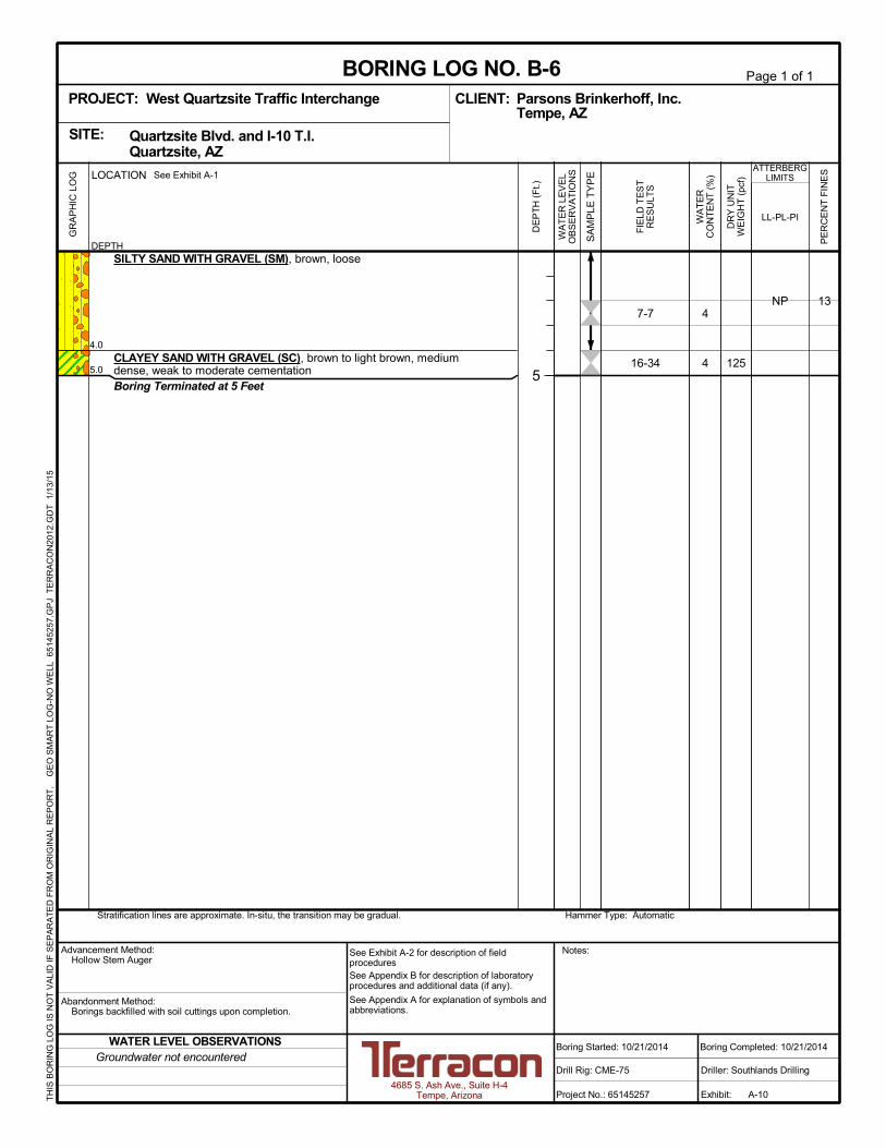
4.0
5.0
SILTY SAND WITH GRAVEL (SM), brown, loose
CLAYEY SAND WITH GRAVEL (SC), brown to light brown, mediumdense, weak to moderate cementationBoring Terminated at 5 Feet
7-7
16-34
134
4 125
NP
Hammer Type: AutomaticStratification lines are approximate. In-situ, the transition may be gradual.
LOCATION
DEPTH
GR
AP
HIC
LO
G See Exhibit A-1
TH
IS B
OR
ING
LO
G IS
NO
T V
ALI
D IF
SE
PA
RA
TE
D F
RO
M O
RIG
INA
L R
EP
OR
T.
G
EO
SM
AR
T L
OG
-NO
WE
LL 6
514
525
7.G
PJ
TE
RR
AC
ON
2012
.GD
T
1/13
/15
SITE:
Page 1 of 1
Advancement Method:Hollow Stem Auger
Abandonment Method:Borings backfilled with soil cuttings upon completion.
4685 S. Ash Ave., Suite H-4Tempe, Arizona
Notes:
Project No.: 65145257
Drill Rig: CME-75
Boring Started: 10/21/2014
BORING LOG NO. B-6Parsons Brinkerhoff, Inc.CLIENT:Tempe, AZ
Driller: Southlands Drilling
Boring Completed: 10/21/2014
Exhibit: A-10
See Exhibit A-2 for description of fieldproceduresSee Appendix B for description of laboratoryprocedures and additional data (if any).
See Appendix A for explanation of symbols andabbreviations.
Quartzsite Blvd. and I-10 T.I. Quartzsite, AZ
PROJECT: West Quartzsite Traffic Interchange
FIE
LD T
ES
TR
ES
ULT
S
PE
RC
EN
T F
INE
S
WA
TE
RC
ON
TE
NT
(%
)
DR
Y U
NIT
WE
IGH
T (
pcf)
ATTERBERGLIMITS
LL-PL-PI
SA
MP
LE T
YP
E
WA
TE
R L
EV
EL
OB
SE
RV
AT
ION
S
DE
PT
H (
Ft.)
5
Groundwater not encounteredWATER LEVEL OBSERVATIONS

4.0
5.0
SILTY SAND WITH GRAVEL (SM), brown, loose
CLAYEY SAND WITH GRAVEL (SC), brown to light brown, mediumdense, weak to moderate cementationBoring Terminated at 5 Feet
8-10
11-21
233
5
116
112
NP
Hammer Type: AutomaticStratification lines are approximate. In-situ, the transition may be gradual.
LOCATION
DEPTH
GR
AP
HIC
LO
G See Exhibit A-1
TH
IS B
OR
ING
LO
G IS
NO
T V
ALI
D IF
SE
PA
RA
TE
D F
RO
M O
RIG
INA
L R
EP
OR
T.
G
EO
SM
AR
T L
OG
-NO
WE
LL 6
514
525
7.G
PJ
TE
RR
AC
ON
2012
.GD
T
1/13
/15
SITE:
Page 1 of 1
Advancement Method:Hollow Stem Auger
Abandonment Method:Borings backfilled with soil cuttings upon completion.
4685 S. Ash Ave., Suite H-4Tempe, Arizona
Notes:
Project No.: 65145257
Drill Rig: CME-75
Boring Started: 10/21/2014
BORING LOG NO. B-7Parsons Brinkerhoff, Inc.CLIENT:Tempe, AZ
Driller: Southlands Drilling
Boring Completed: 10/21/2014
Exhibit: A-11
See Exhibit A-2 for description of fieldproceduresSee Appendix B for description of laboratoryprocedures and additional data (if any).
See Appendix A for explanation of symbols andabbreviations.
Quartzsite Blvd. and I-10 T.I. Quartzsite, AZ
PROJECT: West Quartzsite Traffic Interchange
FIE
LD T
ES
TR
ES
ULT
S
PE
RC
EN
T F
INE
S
WA
TE
RC
ON
TE
NT
(%
)
DR
Y U
NIT
WE
IGH
T (
pcf)
ATTERBERGLIMITS
LL-PL-PI
SA
MP
LE T
YP
E
WA
TE
R L
EV
EL
OB
SE
RV
AT
ION
S
DE
PT
H (
Ft.)
5
Groundwater not encounteredWATER LEVEL OBSERVATIONS
4.0
5.0
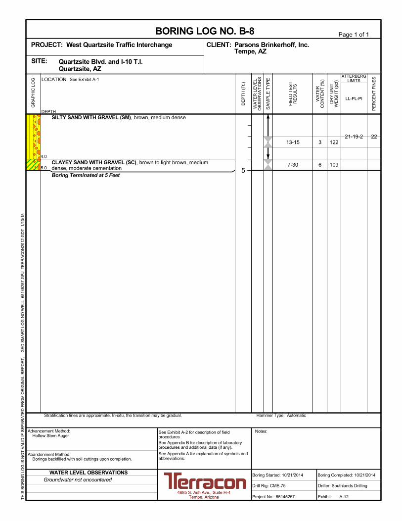
SILTY SAND WITH GRAVEL (SM), brown, medium dense
CLAYEY SAND WITH GRAVEL (SC), brown to light brown, mediumdense, moderate cementationBoring Terminated at 5 Feet
13-15
7-30
223
6
122
109
21-19-2
Hammer Type: AutomaticStratification lines are approximate. In-situ, the transition may be gradual.
LOCATION
DEPTH
GR
AP
HIC
LO
G See Exhibit A-1
TH
IS B
OR
ING
LO
G IS
NO
T V
ALI
D IF
SE
PA
RA
TE
D F
RO
M O
RIG
INA
L R
EP
OR
T.
G
EO
SM
AR
T L
OG
-NO
WE
LL 6
514
525
7.G
PJ
TE
RR
AC
ON
2012
.GD
T
1/13
/15
SITE:
Page 1 of 1
Advancement Method:Hollow Stem Auger
Abandonment Method:Borings backfilled with soil cuttings upon completion.
4685 S. Ash Ave., Suite H-4Tempe, Arizona
Notes:
Project No.: 65145257
Drill Rig: CME-75
Boring Started: 10/21/2014
BORING LOG NO. B-8Parsons Brinkerhoff, Inc.CLIENT:Tempe, AZ
Driller: Southlands Drilling
Boring Completed: 10/21/2014
Exhibit: A-12
See Exhibit A-2 for description of fieldproceduresSee Appendix B for description of laboratoryprocedures and additional data (if any).
See Appendix A for explanation of symbols andabbreviations.
Quartzsite Blvd. and I-10 T.I. Quartzsite, AZ
PROJECT: West Quartzsite Traffic Interchange
FIE
LD T
ES
TR
ES
ULT
S
PE
RC
EN
T F
INE
S
WA
TE
RC
ON
TE
NT
(%
)
DR
Y U
NIT
WE
IGH
T (
pcf)
ATTERBERGLIMITS
LL-PL-PI
SA
MP
LE T
YP
E
WA
TE
R L
EV
EL
OB
SE
RV
AT
ION
S
DE
PT
H (
Ft.)
5
Groundwater not encounteredWATER LEVEL OBSERVATIONS

2.5
SILTY SAND WITH GRAVEL (SM), brown
Boring Terminated at 2.5 Feet
Hammer Type: AutomaticStratification lines are approximate. In-situ, the transition may be gradual.
LOCATION
DEPTH
GR
AP
HIC
LO
G See Exhibit A-1
TH
IS B
OR
ING
LO
G IS
NO
T V
ALI
D IF
SE
PA
RA
TE
D F
RO
M O
RIG
INA
L R
EP
OR
T.
G
EO
SM
AR
T L
OG
-NO
WE
LL 6
514
525
7.G
PJ
TE
RR
AC
ON
2012
.GD
T
1/13
/15
SITE:
Page 1 of 1
Advancement Method:Solid Stem Perc Auger
Abandonment Method:Borings backfilled with soil cuttings upon completion.
4685 S. Ash Ave., Suite H-4Tempe, Arizona
Notes:
Project No.: 65145257
Drill Rig: CME-75
Boring Started: 10/20/2014
BORING LOG NO. PERC-1Parsons Brinkerhoff, Inc.CLIENT:Tempe, AZ
Driller: Southlands Drilling
Boring Completed: 10/20/2014
Exhibit: A-13
See Exhibit A-2 for description of fieldproceduresSee Appendix B for description of laboratoryprocedures and additional data (if any).
See Appendix A for explanation of symbols andabbreviations.
Quartzsite Blvd. and I-10 T.I. Quartzsite, AZ
PROJECT: West Quartzsite Traffic Interchange
FIE
LD T
ES
TR
ES
ULT
S
PE
RC
EN
T F
INE
S
WA
TE
RC
ON
TE
NT
(%
)
DR
Y U
NIT
WE
IGH
T (
pcf)
ATTERBERGLIMITS
LL-PL-PI
SA
MP
LE T
YP
E
WA
TE
R L
EV
EL
OB
SE
RV
AT
ION
S
DE
PT
H (
Ft.)
Groundwater not encounteredWATER LEVEL OBSERVATIONS
2.5
SILTY SAND WITH GRAVEL (SM), brown
Boring Terminated at 2.5 Feet
Hammer Type: AutomaticStratification lines are approximate. In-situ, the transition may be gradual.
LOCATION
DEPTH
GR
AP
HIC
LO
G See Exhibit A-1
TH
IS B
OR
ING
LO
G IS
NO
T V
ALI
D IF
SE
PA
RA
TE
D F
RO
M O
RIG
INA
L R
EP
OR
T.
G
EO
SM
AR
T L
OG
-NO
WE
LL 6
514
525
7.G
PJ
TE
RR
AC
ON
2012
.GD
T
1/13
/15
SITE:
Page 1 of 1
Advancement Method:Solid Stem Perc Auger
Abandonment Method:Borings backfilled with soil cuttings upon completion.
4685 S. Ash Ave., Suite H-4Tempe, Arizona
Notes:
Project No.: 65145257
Drill Rig: CME-75
Boring Started: 10/20/2014
BORING LOG NO. PERC-2Parsons Brinkerhoff, Inc.CLIENT:Tempe, AZ
Driller: Southlands Drilling
Boring Completed: 10/20/2014
Exhibit: A-14
See Exhibit A-2 for description of fieldproceduresSee Appendix B for description of laboratoryprocedures and additional data (if any).
See Appendix A for explanation of symbols andabbreviations.
Quartzsite Blvd. and I-10 T.I. Quartzsite, AZ
PROJECT: West Quartzsite Traffic Interchange
FIE
LD T
ES
TR
ES
ULT
S
PE
RC
EN
T F
INE
S
WA
TE
RC
ON
TE
NT
(%
)
DR
Y U
NIT
WE
IGH
T (
pcf)
ATTERBERGLIMITS
LL-PL-PI
SA
MP
LE T
YP
E
WA
TE
R L
EV
EL
OB
SE
RV
AT
ION
S
DE
PT
H (
Ft.)
Groundwater not encounteredWATER LEVEL OBSERVATIONS

2.5
SILTY SAND WITH GRAVEL (SM), brown
Boring Terminated at 2.5 Feet
Hammer Type: AutomaticStratification lines are approximate. In-situ, the transition may be gradual.
LOCATION
DEPTH
GR
AP
HIC
LO
G See Exhibit A-1
TH
IS B
OR
ING
LO
G IS
NO
T V
ALI
D IF
SE
PA
RA
TE
D F
RO
M O
RIG
INA
L R
EP
OR
T.
G
EO
SM
AR
T L
OG
-NO
WE
LL 6
514
525
7.G
PJ
TE
RR
AC
ON
2012
.GD
T
1/13
/15
SITE:
Page 1 of 1
Advancement Method:Solid Stem Perc Auger
Abandonment Method:Borings backfilled with soil cuttings upon completion.
4685 S. Ash Ave., Suite H-4Tempe, Arizona
Notes:
Project No.: 65145257
Drill Rig: CME-75
Boring Started: 10/20/2014
BORING LOG NO. PERC-3Parsons Brinkerhoff, Inc.CLIENT:Tempe, AZ
Driller: Southlands Drilling
Boring Completed: 10/20/2014
Exhibit: A-15
See Exhibit A-2 for description of fieldproceduresSee Appendix B for description of laboratoryprocedures and additional data (if any).
See Appendix A for explanation of symbols andabbreviations.
Quartzsite Blvd. and I-10 T.I. Quartzsite, AZ
PROJECT: West Quartzsite Traffic Interchange
FIE
LD T
ES
TR
ES
ULT
S
PE
RC
EN
T F
INE
S
WA
TE
RC
ON
TE
NT
(%
)
DR
Y U
NIT
WE
IGH
T (
pcf)
ATTERBERGLIMITS
LL-PL-PI
SA
MP
LE T
YP
E
WA
TE
R L
EV
EL
OB
SE
RV
AT
ION
S
DE
PT
H (
Ft.)
Groundwater not encounteredWATER LEVEL OBSERVATIONS

Geotechnical Engineering ReportWest Quartzsite Traffic Interchange ■ Quartzsite, ArizonaMarch 17, 2015 ■ Terracon Project No. 65145257
Responsive ■ Resourceful ■ Reliable
APPENDIX BLABORATORY TEST RESULTS

Geotechnical Engineering ReportWest Quartzsite Traffic Interchange ■ Quartzsite, ArizonaMarch 17, 2015 ■ Terracon Project No. 65145257
Responsive ■ Resourceful ■ Reliable Exhibit B-1
Laboratory Testing Description
Samples retrieved during the field exploration were taken to the laboratory for furtherobservation by the project geotechnical engineer and were classified in accordance with theUnified Soil Classification System (USCS) described in Appendix B. At that time, the fielddescriptions were confirmed or modified as necessary and an applicable laboratory testingprogram was formulated to determine engineering properties of the subsurface materials.
Laboratory tests were conducted on selected soil samples and the test results are presented inthis appendix. Selected bulk or driven samples of the site soils were combined to makecomposite samples, and these composite samples were tested in the laboratory. The laboratorytest results were used for the geotechnical engineering analyses, and the development ofroadway, foundation and earthwork recommendations. Laboratory tests were performed ingeneral accordance with the applicable ASTM, local or other accepted standards.
Selected soil samples obtained from the site were tested for the following engineeringproperties:
n In-situ Dry Density n In-situ Water Contentn Sieve Analysis n Moisture-Density Relationshipn Atterberg Limits n R-Valuen Consolidation n pH and Minimum Resistivityn Soluble Chloride n Soluble Sulfate
0
10
20
30
40
50
60
0 20 40 60 80 100
CH o
r
OH
CL o
r
OL
ML or OL
MH or OH
PL PIBoring ID Depth Description
SILTY SAND with GRAVEL
WELL-GRADED GRAVEL with SILT and SAND
WELL-GRADED SAND with SILT and GRAVEL
SILTY, CLAYEY SAND with GRAVEL
WELL-GRADED SAND with SILT and GRAVEL
SILTY SAND with GRAVEL
SILTY SAND with GRAVEL
SILTY SAND with GRAVEL
Fines
PLASTICITY
INDEX
LIQUID LIMIT
"U" L
ine
"A" L
ine
NP
NP
NP
7
NP
NP
NP
2
12
7
11
13
10
13
23
22
LL USCS
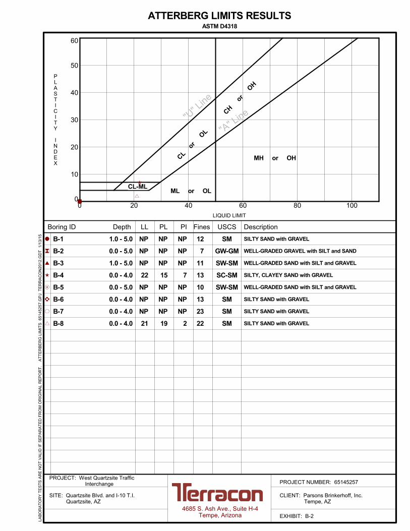
B-1
B-2
B-3
B-4
B-5
B-6
B-7
B-8
ATTERBERG LIMITS RESULTSASTM D4318
NP
NP
NP
15
NP
NP
NP
19
NP
NP
NP
22
NP
NP
NP
21
SM
GW-GM
SW-SM
SC-SM
SW-SM
SM
SM
SM
1.0 - 5.0
0.0 - 5.0
1.0 - 5.0
0.0 - 4.0
0.0 - 5.0
0.0 - 4.0
0.0 - 4.0
0.0 - 4.0
4685 S. Ash Ave., Suite H-4Tempe, Arizona
PROJECT NUMBER: 65145257PROJECT: West Quartzsite Traffic
Interchange
SITE: Quartzsite Blvd. and I-10 T.I. Quartzsite, AZ
CLIENT: Parsons Brinkerhoff, Inc. Tempe, AZ
EXHIBIT: B-2
LAB
OR
AT
OR
Y T
ES
TS
AR
E N
OT
VA
LID
IF S
EP
AR
AT
ED
FR
OM
OR
IGIN
AL
RE
PO
RT
.
AT
TE
RB
ER
G L
IMIT
S 6
5145
257.
GP
J T
ER
RA
CO
N20
12.G
DT
1/
13/1
5
CL-ML
0
5
10
15
20
25
30
35
40
45
50
55
60
65
70
75
80
85
90
95
100
0.0010.010.1110100
30 40
GRAIN SIZE DISTRIBUTION
U.S. SIEVE OPENING IN INCHES
ASTM D422
USCS Classification Boring ID Depth LL
D100 D30
Cc Cu
Boring ID Depth D60 %Clay
NP
NP
NP
22
2.05
1.59
1.76
80.23
58.27
29.31
U.S. SIEVE NUMBERS
SILT OR CLAY
4 50
AASHTO Classification
1.5
1 - 5
0 - 4.999
1 - 5
0 - 4
6 16 20
PL PI
D10 %Gravel %Sand %Silt
NP
NP
NP
15
NP
NP
NP
7
3/8 3 100 1403 2
COBBLESGRAVEL
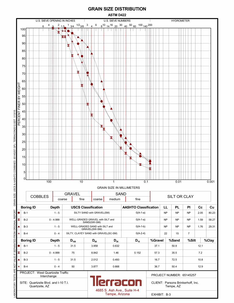
0(A-1-a)
0(A-1-a)
0(A-1-b)
0(A-2-4)
SANDcoarse medium
GRAIN SIZE IN MILLIMETERS
PE
RC
EN
T F
INE
R B
Y W
EIG
HT
coarse fine
2006 810 14
31.5
75
31.5
50
0.632
1.46
0.493
0.668
0.152
37.1
57.3
16.7
36.7
50.9
35.5
72.5
50.4
B-1
B-2
B-3
B-4
1 - 5
0 - 4.999
1 - 5
0 - 4
41 3/4 1/2 60
fine
HYDROMETER
B-1
B-2
B-3
B-4
3.958
8.842
2.012
3.877
12.1
7.2
10.8
12.9
SILTY SAND with GRAVEL(SM)
WELL-GRADED GRAVEL with SILT andSAND(GW-GM)
WELL-GRADED SAND with SILT andGRAVEL(SW-SM)
SILTY, CLAYEY SAND with GRAVEL(SC-SM)
4685 S. Ash Ave., Suite H-4Tempe, Arizona
PROJECT NUMBER: 65145257PROJECT: West Quartzsite Traffic
Interchange
SITE: Quartzsite Blvd. and I-10 T.I. Quartzsite, AZ
CLIENT: Parsons Brinkerhoff, Inc. Tempe, AZ
EXHIBIT: B-3
LAB
OR
AT
OR
Y T
ES
TS
AR
E N
OT
VA
LID
IF S
EP
AR
AT
ED
FR
OM
OR
IGIN
AL
RE
PO
RT
.
GR
AIN
SIZ
E: U
SC
S &
AA
SH
TO
CO
MB
INE
D 6
514
5257
.GP
J T
ER
RA
CO
N20
12.G
DT
1/1
3/15

0
5
10
15
20
25
30
35
40
45
50
55
60
65
70
75
80
85
90
95
100
0.0010.010.1110100
30 40
GRAIN SIZE DISTRIBUTION
U.S. SIEVE OPENING IN INCHES
ASTM D422
USCS Classification Boring ID Depth LL
D100 D30
Cc Cu
Boring ID Depth D60 %Clay
NP
NP
NP
21
1.23 67.03
U.S. SIEVE NUMBERS
SILT OR CLAY
4 50
AASHTO Classification
1.5
0 - 5
0 - 4
0 - 4
0 - 4
6 16 20
PL PI
D10 %Gravel %Sand %Silt
NP
NP
NP
19
NP
NP
NP
2
3/8 3 100 1403 2
COBBLESGRAVEL
0(A-1-a)
0(A-1-b)
0(A-1-b)
0(A-1-b)
SANDcoarse medium
GRAIN SIZE IN MILLIMETERS
PE
RC
EN
T F
INE
R B
Y W
EIG
HT
coarse fine
2006 810 14
31.5
37.5
31.5
31.5
0.661
0.653
0.14
0.17
40.6
22.8
19.6
24.4
49.2
63.3
57.2
53.7
B-5
B-6
B-7
B-8
0 - 5
0 - 4
0 - 4
0 - 4
41 3/4 1/2 60
fine
HYDROMETER
B-5
B-6
B-7
B-8
4.881
2.64
1.565
1.712
10.2
12.6
23.2
21.9
WELL-GRADED SAND with SILT andGRAVEL(SW-SM)
SILTY SAND with GRAVEL(SM)
SILTY SAND with GRAVEL(SM)
SILTY SAND with GRAVEL(SM)
4685 S. Ash Ave., Suite H-4Tempe, Arizona
PROJECT NUMBER: 65145257PROJECT: West Quartzsite Traffic
Interchange
SITE: Quartzsite Blvd. and I-10 T.I. Quartzsite, AZ
CLIENT: Parsons Brinkerhoff, Inc. Tempe, AZ
EXHIBIT: B-4
LAB
OR
AT
OR
Y T
ES
TS
AR
E N
OT
VA
LID
IF S
EP
AR
AT
ED
FR
OM
OR
IGIN
AL
RE
PO
RT
.
GR
AIN
SIZ
E: U
SC
S &
AA
SH
TO
CO
MB
INE
D 6
514
5257
.GP
J T
ER
RA
CO
N20
12.G
DT
1/1
3/15

75
80
85
90
95
100
105
110
115
120
125
130
135
0 5 10 15 20 25 30 35 40 45
Test Method
Remarks:
TEST RESULTS
PIPLLL
ATTERBERG LIMITS
PCF
% Maximum Dry Density
Optimum Water Content
132.6
% Percent Fines
8.6
DR
Y D
EN
SIT
Y,
pcf
WATER CONTENT, %
ZAV for Gs = 2.8
ZAV for Gs = 2.7
ZAV for Gs = 2.6
Source of Material
Description of Material
ASTM D698 Method A
MOISTURE-DENSITY RELATIONSHIPASTM D698/D1557
SILTY CLAYEY SAND WITH
GRAVEL(SC-SM)
B-1 @ 15.0 - 19.0 ft
4685 S. Ash Ave., Suite H-4Tempe, Arizona
PROJECT NUMBER: 65145257PROJECT: West Quartzsite Traffic
Interchange
SITE: Quartzsite Blvd. and I-10 T.I. Quartzsite, AZ
CLIENT: Parsons Brinkerhoff, Inc. Tempe, AZ
EXHIBIT: B-5
LAB
OR
AT
OR
Y T
ES
TS
AR
E N
OT
VA
LID
IF S
EP
AR
AT
ED
FR
OM
OR
IGIN
AL
RE
PO
RT
.
SW
_CO
MP
AC
TIO
N -
V2
651
452
57.G
PJ
TE
RR
AC
ON
2012
.GD
T 1
/13/
15

75
80
85
90
95
100
105
110
115
120
125
130
135
0 5 10 15 20 25 30 35 40 45
Test Method
Remarks:
TEST RESULTS
PIPLLL
ATTERBERG LIMITS
NP NP NP
PCF
% Maximum Dry Density
Optimum Water Content
131.3
% Percent Fines
8.1
7.2
DR
Y D
EN
SIT
Y,
pcf
WATER CONTENT, %
ZAV for Gs = 2.8
ZAV for Gs = 2.7
ZAV for Gs = 2.6
Source of Material
Description of Material
ASTM D698 Method C
MOISTURE-DENSITY RELATIONSHIPASTM D698/D1557
WELL-GRADED GRAVEL with
SILT and SAND(GW-GM)
B-2 @ 0.0 - 5.0 ft
4685 S. Ash Ave., Suite H-4Tempe, Arizona
PROJECT NUMBER: 65145257PROJECT: West Quartzsite Traffic
Interchange
SITE: Quartzsite Blvd. and I-10 T.I. Quartzsite, AZ
CLIENT: Parsons Brinkerhoff, Inc. Tempe, AZ
EXHIBIT: B-6
LAB
OR
AT
OR
Y T
ES
TS
AR
E N
OT
VA
LID
IF S
EP
AR
AT
ED
FR
OM
OR
IGIN
AL
RE
PO
RT
.
SW
_CO
MP
AC
TIO
N -
V2
651
452
57.G
PJ
TE
RR
AC
ON
2012
.GD
T 1
/13/
15

75
80
85
90
95
100
105
110
115
120
125
130
135
0 5 10 15 20 25 30 35 40 45
Test Method
Remarks:
TEST RESULTS
PIPLLL
ATTERBERG LIMITS
21 19 2
PCF
% Maximum Dry Density
Optimum Water Content
127.2
% Percent Fines
9.2
21.9
DR
Y D
EN
SIT
Y,
pcf
WATER CONTENT, %
ZAV for Gs = 2.8
ZAV for Gs = 2.7
ZAV for Gs = 2.6
Source of Material
Description of Material
ASTM D698 Method A
MOISTURE-DENSITY RELATIONSHIPASTM D698/D1557
SILTY SAND with GRAVEL(SM)
B-8 @ 0.0 - 4.0 ft
4685 S. Ash Ave., Suite H-4Tempe, Arizona
PROJECT NUMBER: 65145257PROJECT: West Quartzsite Traffic
Interchange
SITE: Quartzsite Blvd. and I-10 T.I. Quartzsite, AZ
CLIENT: Parsons Brinkerhoff, Inc. Tempe, AZ
EXHIBIT: B-7
LAB
OR
AT
OR
Y T
ES
TS
AR
E N
OT
VA
LID
IF S
EP
AR
AT
ED
FR
OM
OR
IGIN
AL
RE
PO
RT
.
SW
_CO
MP
AC
TIO
N -
V2
651
452
57.G
PJ
TE
RR
AC
ON
2012
.GD
T 1
/13/
15

-20
-18
-16
-14
-12
-10
-8
-6
-4
-2
0
2
4
100 1,000 10,000
AX
IAL
ST
RA
IN,
%
PRESSURE, psf
ASTM D2435
NOTES:
SWELL CONSOLIDATION TEST
4685 S. Ash Ave., Suite H-4Tempe, Arizona
PROJECT NUMBER: 65145257PROJECT: West Quartzsite Traffic
Interchange
SITE: Quartzsite Blvd. and I-10 T.I. Quartzsite, AZ
CLIENT: Parsons Brinkerhoff, Inc. Tempe, AZ
EXHIBIT: B-8
Specimen Identification Classification , pcf
B-2
WC, %
CLAYEY SAND WITH GRAVEL(SC) 31204.0 - 5.0 ft
LAB
OR
AT
OR
Y T
ES
TS
AR
E N
OT
VA
LID
IF S
EP
AR
AT
ED
FR
OM
OR
IGIN
AL
RE
PO
RT
.
SW
_CO
NS
OL_
ST
RA
IN-U
SC
S 6
5145
257
.GP
J T
ER
RA
CO
N20
12.G
DT
1/
13/1
5
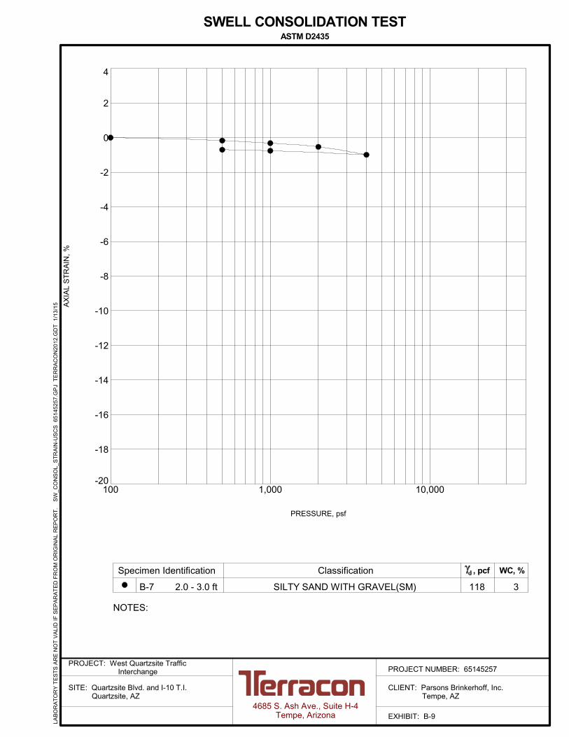
-20
-18
-16
-14
-12
-10
-8
-6
-4
-2
0
2
4
100 1,000 10,000
AX
IAL
ST
RA
IN,
%
PRESSURE, psf
ASTM D2435
NOTES:
SWELL CONSOLIDATION TEST
4685 S. Ash Ave., Suite H-4Tempe, Arizona
PROJECT NUMBER: 65145257PROJECT: West Quartzsite Traffic
Interchange
SITE: Quartzsite Blvd. and I-10 T.I. Quartzsite, AZ
CLIENT: Parsons Brinkerhoff, Inc. Tempe, AZ
EXHIBIT: B-9
Specimen Identification Classification , pcf
B-7
WC, %
SILTY SAND WITH GRAVEL(SM) 31182.0 - 3.0 ft
LAB
OR
AT
OR
Y T
ES
TS
AR
E N
OT
VA
LID
IF S
EP
AR
AT
ED
FR
OM
OR
IGIN
AL
RE
PO
RT
.
SW
_CO
NS
OL_
ST
RA
IN-U
SC
S 6
5145
257
.GP
J T
ER
RA
CO
N20
12.G
DT
1/
13/1
5

4685 South Ash Avenue, Suite H-4Tempe, Arizona 85282(480) 897-8200 FAX(480) 897-1133
RESISTANCE R-VALUE & EXPANSIONPRESSURE OF COMPACTED SOIL
ASTM D2844PROJECT: Quartzsite Blvd. Widening ImprovementsLOCATION: Quartzsite Blvd. & I-10 T.I.PROJECT NO. 65125257CLASSIFICATION: WELL GRADED SAND WITH SILT AND GRAVEL(SW-SM)SAMPLE: B-3 @ 1
SAMPLE DATA TEST RESULTSTEST SPECIMEN NO. 1 2 3COMPACTION PRESSURE (PSI) 110 150 200DENSITY (PCF) 125.3 126.1 130.6MOISTURE CONTENT (%) 9.3 8.4 7.1EXPANSION PRESSURE (PSI) -0.25 -0.06 0.12HORIZONTAL PRESSURE @ 160 PSI 90 34 18SAMPLE HEIGHT (INCHES) 2.43 2.48 2.40EXUDATION PRESSURE (PSI) 95.9 265.7 521.9CORRECTED R-VALUE 32.2 69.8 78.9UNCORRECTED R-VALUE 33.2 69.8 82.2
R-VALUE @ 300 PSI EXUDATION PRESSURE = 73
0
10
20
30
40
50
60
70
80
90
100
0 100 200 300 400 500 600 700 800
R-V
ALU
E
EXUDATION PRESSURE - PSI
Exhibit B-10

4685 South Ash Avenue, Suite H-4Tempe, Arizona 85282(480) 897-8200 FAX(480) 897-1133
RESISTANCE R-VALUE & EXPANSIONPRESSURE OF COMPACTED SOIL
ASTM D2844PROJECT: Quartzsite Blvd. Widening ImprovementsLOCATION: Quartzsite Blvd. & I-10 T.I.PROJECT NO. 65125257CLASSIFICATION: SILTY SAND WITH GRAVEL(SM)SAMPLE: B-7 @ 0
SAMPLE DATA TEST RESULTSTEST SPECIMEN NO. 1 2 3COMPACTION PRESSURE (PSI) 150 200 250DENSITY (PCF) 128.7 130.7 133.9MOISTURE CONTENT (%) 8.3 7.7 5.6EXPANSION PRESSURE (PSI) -0.28 -0.06 0.31HORIZONTAL PRESSURE @ 160 PSI 35 25 18SAMPLE HEIGHT (INCHES) 2.53 2.53 2.53EXUDATION PRESSURE (PSI) 175.0 254.6 520.7CORRECTED R-VALUE 64.0 74.1 82.1UNCORRECTED R-VALUE 64.0 74.1 82.1
R-VALUE @ 300 PSI EXUDATION PRESSURE = 77
0
10
20
30
40
50
60
70
80
90
100
0 100 200 300 400 500 600 700 800
R-V
ALU
E
EXUDATION PRESSURE - PSI
Exhibit B-11

B-1 1.0 - 5.0 SM 12 NP NP NPB-1 4.0 - 4.9 SM 127 3 1, 2
B-1 9.0 - 10.0 SC-SM 123 3 1, 2
B-1 14.0 - 14.8 SC-SM 125 4 1, 2B-1 19.0 - 20.0 SM 114 2 1, 2
B-1 24.0 - 24.9 SM 120 1 1, 2B-1 29.0 - 29.8 SM 122 2 1, 2
B-2 0.0 - 5.0 GW-GM 7 NP NP NP
B-2 4.0 - 5.0 SC 120 3 1, 2B-3 1.0 - 5.0 SW-SM 11 NP NP NP
B-3 2.0 - 3.0 SW-SM 112 4 1, 2B-3 5.0 - 6.0 GM 114 3 1, 2
B-3 7.0 - 8.0 SC-SM 118 5 1, 2
B-3 9.0 - 9.9 GM 133 4 1, 2B-4 0.0 - 4.0 SC-SM 13 22 15 7
B-4 2.0 - 3.0 SC-SM 130 3 1, 2B-4 5.0 - 6.0 SC-SM 127 3 1, 2
B-5 0.0 - 5.0 SW-SM 10 NP NP NP
B-5 2.0 - 2.9 SW-SM 121 3 1, 2B-5 5.0 - 6.0 SW-SM 123 2 1, 2
B-5 7.0 - 8.0 SC 120 4 1, 2B-5 9.0 - 9.9 SC-SM 121 5 1, 2
B-6 0.0 - 4.0 SM 13 NP NP NP 6.8 630 130 390
B-6 2.0 - 3.0 SM 4 2B-6 4.0 - 5.0 SC 125 4 1, 2
50pH Resistivity
(ohm-cm)Sulfates(ppm)
Chlorides(ppm)
DryDensity
(pcf)
Expansion(%)
Corrosivity
Dry Density(pcf)
Atterberg Limits
In-Situ Properties
Passing#200
Sieve (%)
Classification
PL PI
WaterContent
(%)
Remarks
Expansion Testing
Surcharge(psf)
WaterContent (%) LL
USCSSoil
Class.Expansion
IndexEI
REMARKS1. Dry Density and/or moisture determined from one or more rings of a multi-ring sample.2. Visual Classification.3. Submerged to approximate saturation.4. Expansion Index in accordance with ASTM D4829-95.5. Air-Dried Sample
BoreholeNo.
Depth(ft.)
SUMMARY OF LABORATORY RESULTS
PROJECT: West Quartzsite Traffic Interchange PROJECT NUMBER: 65145257
CLIENT: Parsons Brinkerhoff, Inc. Tempe, AZ
SITE: Quartzsite Blvd. and I-10 T.I. Quartzsite, AZ
PH. 480-897-8200 FAX. 480-897-1133
4685 S. Ash Ave., Suite H-4Tempe, Arizona
EXHIBIT: B-12
TH
IS B
OR
ING
LO
G IS
NO
T V
ALI
D IF
SE
PA
RA
TE
D F
RO
M O
RIG
INA
L R
EP
OR
T.
S
OIL
PR
OP
ER
TIE
S 2
651
4525
7.G
PJ
TE
RR
AC
ON
2012
.GD
T 1
/13/
15

B-7 0.0 - 4.0 SM 23 NP NP NP 7.5 670 54 440B-7 2.0 - 3.0 SM 116 3 1, 2
B-7 4.0 - 5.0 SC 112 5 1, 2
B-8 0.0 - 4.0 SM 22 21 19 2 7.2 590 890 450B-8 2.0 - 3.0 SM 122 3 1, 2
B-8 4.0 - 5.0 SC 109 6 1, 2
50pH Resistivity
(ohm-cm)Sulfates(ppm)
Chlorides(ppm)
DryDensity
(pcf)
Expansion(%)
Corrosivity
Dry Density(pcf)
Atterberg Limits
In-Situ Properties
Passing#200
Sieve (%)
Classification
PL PI
WaterContent
(%)
Remarks
Expansion Testing
Surcharge(psf)
WaterContent (%) LL
USCSSoil
Class.Expansion
IndexEI
REMARKS1. Dry Density and/or moisture determined from one or more rings of a multi-ring sample.2. Visual Classification.3. Submerged to approximate saturation.4. Expansion Index in accordance with ASTM D4829-95.5. Air-Dried Sample
BoreholeNo.
Depth(ft.)
SUMMARY OF LABORATORY RESULTS
PROJECT: West Quartzsite Traffic Interchange PROJECT NUMBER: 65145257
CLIENT: Parsons Brinkerhoff, Inc. Tempe, AZ
SITE: Quartzsite Blvd. and I-10 T.I. Quartzsite, AZ
PH. 480-897-8200 FAX. 480-897-1133
4685 S. Ash Ave., Suite H-4Tempe, Arizona
EXHIBIT: B-13
TH
IS B
OR
ING
LO
G IS
NO
T V
ALI
D IF
SE
PA
RA
TE
D F
RO
M O
RIG
INA
L R
EP
OR
T.
S
OIL
PR
OP
ER
TIE
S 2
651
4525
7.G
PJ
TE
RR
AC
ON
2012
.GD
T 1
/13/
15

B-1 1 SM NP NP 12 15 21 25 29 39 48 52 63 71 82 90 97 98B-2 0 GW-GM NP NP 7 10 14 17 21 28 33 35 43 50 62 71 82 89 94 97 100 100
B-3 1 SW-SM NP NP 11 17 24 28 33 47 60 65 83 88 92 94 97 98
B-4 0 SC-SM 22 7 13 16 20 24 28 39 48 52 63 69 77 83 91 95 98 100B-5 0 SW-SM NP NP 10 14 20 24 29 38 45 48 59 66 77 84 93 96
B-6 0 SM NP NP 13 16 20 24 28 42 53 57 76 82 88 92 95 97 99B-7 0 SM NP NP 23 31 37 40 45 55 64 68 80 85 91 94 98 99
B-8 0 SM 21 2 22 29 36 40 44 54 63 66 76 80 86 89 97 99
USCSSoil
Class.
Depth(ft.)
BoreholeNo.
AtterbergLimits
PI
Coarse
#200 #50 #40 #10 #4
SAND
Fine Medium
SILTor
CLAY
#100 #30 #16 #8 1/4" 3/8" 1½"
GRAVEL
Coarse
LL 1/2" 3/4" 1"
Fine
2" 3" >3"
COBBLESand
BOULDERS
REMARKS1.2.3.4.
4685 S. Ash Ave., Suite H-4Tempe, Arizona
PH. 480-897-8200 FAX. 480-897-1133
PROJECT: West Quartzsite Traffic Interchange PROJECT NUMBER: 65145257
CLIENT: Parsons Brinkerhoff, Inc. Tempe, AZ
SITE: Quartzsite Blvd. and I-10 T.I. Quartzsite, AZ
SUMMARY OF GRAIN SIZE DISTRIBUTION
EXHIBIT: B-14
TH
IS B
OR
ING
LO
G IS
NO
T V
ALI
D IF
SE
PA
RA
TE
D F
RO
M O
RIG
INA
L R
EP
OR
T.
S
IEV
E A
NA
LYS
ES
- T
AB
ULA
R 6
5145
257
.GP
J T
ER
RA
CO
N20
12.G
DT
1/1
3/1
5