geotechnical engineering report -...
TRANSCRIPT
Geotechnical Engineering Report Proposed Cleveland Nissan
Cleveland, Bradley County, Tennessee
January 23, 2015
Terracon Project No. E2155001
Prepared for:
Sonic Automotive, Inc. - Facility Development
Charlotte, North Carolina
Prepared by:
Terracon Consultants, Inc.
Chattanooga, Tennessee


Responsive ■ Resourceful ■ Reliable
TABLE OF CONTENTS Page
EXECUTIVE SUMMARY ............................................................................................................. i
1.0 INTRODUCTION ................................................................................................................. 1
2.0 PROJECT INFORMATION ................................................................................................. 1
2.1 Project Description .............................................................................................. 1
2.2 Site Location and Description ............................................................................. 2
3.0 SUBSURFACE CONDITIONS ............................................................................................ 2
3.1 Site Geology ........................................................................................................ 2
3.2 Typical Subsurface Profile .................................................................................... 3
3.3 Groundwater ....................................................................................................... 4
4.0 RECOMMENDATIONS FOR DESIGN AND CONSTRUCTION ......................................... 4
4.1 Geotechnical Considerations ................................................................................ 4
4.2 Earthwork ........................................................................................................... 5
4.2.1 Site Preparation ....................................................................................... 5
4.2.2 Fill Materials Requirements ..................................................................... 6
4.2.3 Fill Placement and Compaction Requirements ........................................ 7
4.2.4 Utility Trench Backfill ................................................................................. 7
4.2.5 Grading and Drainage............................................................................... 8
4.2.6 Construction Considerations ..................................................................... 8
4.3 Foundations ........................................................................................................ 9
4.3.1 Design Recommendations ....................................................................... 9
4.3.2 Construction Considerations ...................................................................10
4.4 Seismic Considerations......................................................................................11
4.5 Floor Slab ..........................................................................................................11
4.5.1 Design Recommendations ......................................................................11
4.5.2 Construction Considerations ...................................................................12
4.6 Pavements .........................................................................................................12
4.6.1 Subgrade Preparation ..............................................................................12
4.6.2 Estimates of Minimum Pavement Thickness ............................................13
4.6.3 Pavement Drainage ................................................................................14
4.6.4 Pavement Maintenance ...........................................................................14
5.0 GENERAL COMMENTS ................................................................................................... 15

Responsive ■ Resourceful ■ Reliable
TABLE OF CONTENTS – continued
APPENDIX – FIELD EXPLORATION
Exhibit A-1 Site Location
Exhibit A-2 Exploration Diagram
Exhibit A-3 Field Exploration Description
Exhibit A-4 to A-21 Boring Logs
APPENDIX B – LABORATORY TESTING
Exhibit B-1 Laboratory Testing
Exhibit B-2 to B-3 Grain Size Distribution Analysis
APPENDIX C – SUPPORTING DOCUMENTS
Exhibit C-1 General Notes
Exhibit C-2 Unified Soil Classification System

Geotechnical Engineering Report
Proposed Cleveland Nissan ■ Cleveland, Tennessee
January 23, 2015 ■ Terracon Project No. E2155001
Responsive ■ Resourceful ■ Reliable i
EXECUTIVE SUMMARY
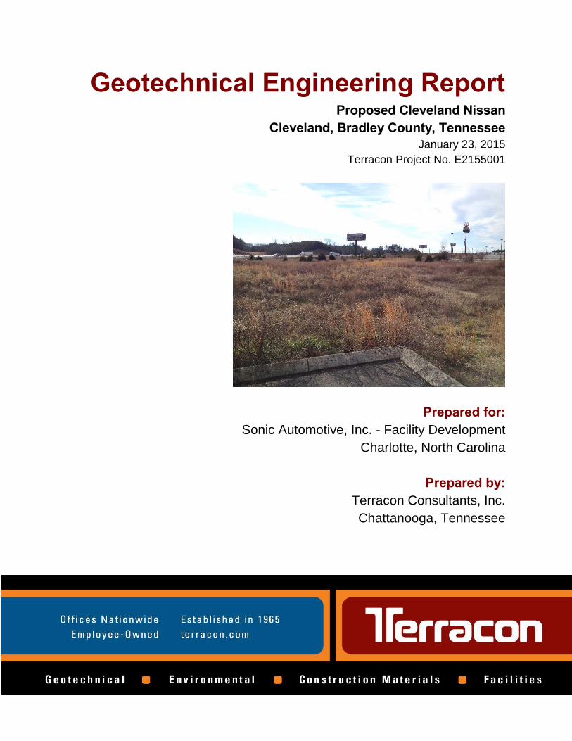
Terracon performed a geotechnical exploration and evaluation for the Proposed Cleveland Nissan
to be located southwest of the intersection of Pleasant Grove Road and Interstate-75 in Cleveland,
Bradley County, Tennessee. The findings and pertinent geotechnical engineering
recommendations are summarized below:
Eighteen soil borings were drilled at the site, generally encountering stiff to very stiff, low-
plasticity silt and clay with varying sand and weathered shale content. In our opinion, the
proposed retail building can be supported on shallow foundation systems bearing on the stiff
to very stiff, native soils or on compacted structural fill extending to suitable soils, designed
for a net allowable bearing pressure of 3,000 psf.
Soil in the upper 1 to 2 feet of the soil profile appears to have become soft due to poor
drainage on the site in about a third of the borings. Undercutting these soft soils near the
surface may be necessary to prepare the area for building and pavement construction. The
onsite soils generally appear suitable for reuse as fill material provided they are moisture
conditioned and compacted as recommended in this report.
The existing one-story, metal building and associated asphalt parking lot located in the
northeastern portion of the site will be demolished during the proposed construction. We
recommend removing all existing foundations, floor slabs, buried utilities, pavement, and
otherwise unsuitable material from the project area and thoroughly proofrolling the subgrade
prior to new fill placement.
Previously placed fill material was encountered in the upper 3 to 5 feet in several pavement
area soil borings, predominately on the eastern side of the site. Results of field penetration
testing indicate that the fill was likely placed with some compactive effort. Prior to new
pavement construction, these areas should be thoroughly proofrolled to identify areas of soft
or loose material. This risk that unsuitable materials buried within the fill will not be discovered
cannot be eliminated without completely removing the existing fill, but can be reduced by
performing additional testing and evaluation.
The 2012 International Building Code seismic site classification for this site is C.
Close monitoring of the construction operations discussed herein will be critical in
achieving the design subgrade support. We therefore recommend that Terracon be
retained to monitor this portion of the work.
This summary should be used in conjunction with the entire report for design purposes. It should
be recognized that details were not included or fully developed in this section, and the entire report
must be read for a comprehensive understanding of the items contained herein. The section titled
GENERAL COMMENTS should be read for an understanding of the report limitations.

GEOTECHNICAL ENGINEERING REPORT
PROPOSED CLEVELAND NISSAN
PLEASANT GROVE ROAD
CLEVELAND, BRADLEY COUNTY, TENNESSEE Terracon Project No. E2155001
January 23, 2015
1.0 INTRODUCTION
This report presents the results of our geotechnical engineering services performed for the Proposed
Cleveland Nissan to be located southwest of the intersection of Pleasant Grove Road and Interstate-
75 in Cleveland, Bradley County, Tennessee. Our geotechnical engineering scope of work for this
project included the advancement of eighteen (18) soil test borings to approximate depths ranging
from 5 to 32½ feet below the ground surface in the proposed building and parking lot areas.
The purpose of these services is to provide information and geotechnical engineering
recommendations relative to:
subsurface soil conditions groundwater conditions
earthwork foundation design and construction
pavement design and construction floor slab design and construction
seismic considerations
2.0 PROJECT INFORMATION
2.1 Project Description
ITEM DESCRIPTION
Site layout Please refer to the Site Location and Exploration Plan (Exhibits A-1
and A-2 in Appendix A) for site layout.
Proposed Structure One-story building, approximately 10,000 square feet.
Building construction
(Assumed)
Structural steel construction with a spread footing foundation
systems and concrete slab-on-grade floors.
Finished floor elevation Assumed to be near existing elevations. Near EL 889 feet.
Maximum loads
Building:
Column Load – 50 to 300 kips (assumed)
Continuous Load-Bearing Wall Loads – 4 to 6 klf (assumed)
Maximum Uniform Floor Slab Load – 150 psf (assumed)
Grading in building and
parking area Maximum cut and fill anticipated to be on the order of 5 to 7 feet.

Geotechnical Engineering Report
Proposed Cleveland Nissan ■ Cleveland, Tennessee
January 23, 2015 ■ Terracon Project No. E2155001
Responsive ■ Resourceful ■ Reliable 2
ITEM DESCRIPTION
Pavement areas
Paved parking areas are planned to the northeast and southwest of
the proposed building with a paved entry drive from Pleasant Grove
Road.
Retaining walls None anticipated
Below Grade Areas None anticipated
2.2 Site Location and Description
ITEM DESCRIPTION
Location
The site is located southwest of the intersection of Pleasant Grove
Road and Interstate-75 in Cleveland, Bradley County, Tennessee.
35.151475° N; 84.951281° W
Existing Improvements
An existing building is currently present in the northern portion of
the subject site, along with an asphalt paved parking area. The
majority of the site is undeveloped, but has been previously graded.
The existing building appears to be a single-story, metal building
with a concrete slab on grade with no below grade areas. The
foundations for the existing buildings are unknown at this time;
however, we anticipate the existing buildings are supported on
shallow spread footing foundation systems. The existing parking
surfaces generally consist of asphalt pavement with some areas of
concrete pavement.
Current ground cover
Ground cover in the area of the proposed project consists of an
existing building near Pleasant Grove Road and soil with scattered,
low vegetation over most the remainder of the site
Existing topography
The site gradually slopes downwards from west to east, from
approximately elevation 895 to 881 feet. A fill slope is located
near the southern site boundary, supporting the southbound on-
ramp for Interstate-75. Surface water drainage in portions of the
site is poor, allowing water to pond in some areas.
3.0 SUBSURFACE CONDITIONS
3.1 Site Geology
The project site is located within the Valley and Ridge Physiographic Province, which is comprised
of sedimentary sequences that were deposited during the Paleozoic Era. According to geologic
mapping of the area, the project site is underlain by the Rome Formation, which consists of shale
and siltstone with beds of fine-grained sandstone.

Geotechnical Engineering Report
Proposed Cleveland Nissan ■ Cleveland, Tennessee
January 23, 2015 ■ Terracon Project No. E2155001
Responsive ■ Resourceful ■ Reliable 3
The project site is located near the contact of the Rome Formation and the Conasauga Group.
The Conasauga Group is comprised of formations that consist predominately of limestone,
dolomite, and shale. It should be noted that the site could be underlain by carbonate bedrock that
is susceptible to dissolution along joints and bedding planes in the rock mass. This can result in
voids and solution channels within the rock strata and a highly irregular bedrock surface. The
weathering of the bedrock and subsequent collapse or erosion of the overburden into these openings
results in what is referred to as karst topography, if there is an abundance of voids and solution
channels. Any construction in karst topography is accompanied by some degree of risk for future
internal soil erosion and ground subsidence that could affect the stability of the proposed structure.
Our limited subsurface investigation at the site did not reveal any obvious signs of karst activity. The
project site is not expected to be at any greater risk for sinkholes than the nearby structures located
in the same geologic formation.
3.2 Typical Subsurface Profile
Eighteen (18) soil borings, designated B-1 through B-18, were advanced at the project site in the
area of the proposed building and in the proposed pavement areas. With the exception of Boring
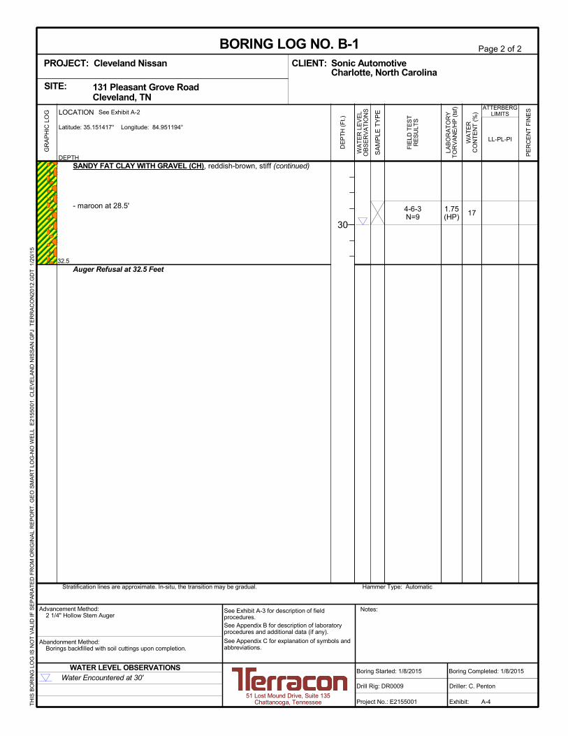
B-1, all borings were drilled to their planned termination depth. Boring B-1 encountered auger
refusal, presumably at the weathered bedrock surface, at a depth of approximately 32½ feet below
ground surface (bgs). The remaining borings were drilled to depths varying from 5 to 25 feet bgs
without encountering refusal.
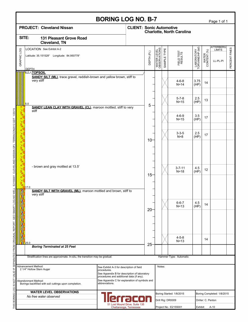
Borings B-1 through B-7 were located in the proposed building footprint. Beneath approximately 2
to 3 inches of topsoil, the borings generally encountered stiff to very stiff, low-plasticity silt and clay,
with varying sand and rock content. Soft to medium stiff soil was found in 3 of the borings from the
surface to a depth of 1 and 2 feet. These included B-2, B-3, and B-6. Beneath a minimum depth of
8 feet bgs, stiff to very stiff, high-plasticity clay was encountered at depth in 5 of the 7 building area
borings. The upper 3 feet bgs in Borings B-1 and B-5 and the upper 8 feet bgs in Boring B-4
contained soil which predominately consisted of coarse-grain material. Results of Standard
Penetration Testing (SPT) in these areas indicated that the coarse-grained material was medium
dense.
Borings B-8 through B-18 were located in the proposed pavement areas. Similar to the soils
disclosed in the proposed building area, generally stiff to very stiff, low-plasticity silt and clay were
encountered. However the upper 1 to 2 feet of soil in borings B-8, B-11, B-13 and B-16 appeared to
be soft to medium stiff. Previously placed fill material was encountered in the upper approximately
3 feet bgs in Borings B-8, B-11, B-12, B-16, and B-17, and in the upper approximately 5 feet bgs in
Boring B-18. The fill consisted of both predominately fine-grained and predominately coarse-grained
soil and produced SPT N-values ranging from 9 to 18 blows per foot. The fill was underlain by stiff
to very stiff, native soil.
Geotechnical Engineering Report
Proposed Cleveland Nissan ■ Cleveland, Tennessee
January 23, 2015 ■ Terracon Project No. E2155001
Responsive ■ Resourceful ■ Reliable 4
Specific conditions encountered at each boring location are indicated on the individual logs.
Stratification boundaries on the boring logs represent the approximate location of changes in soil
types; in-situ, the transition between materials may be gradual. Details for each of the borings can
be found on the logs included in Appendix A.
3.3 Groundwater
The boreholes were observed while drilling and at completion of the borings for the presence and
level of groundwater. Groundwater was encountered at an approximate depth of 30 feet bgs in
Boring B-1. Groundwater was not observed in the remaining borings during drilling activities;
however, this does not necessarily mean these borings terminated above groundwater. Due to
the low permeability of the soils encountered in the borings, a relatively long period of time may
be necessary for a groundwater level to develop and stabilize in a borehole in these materials.
Long term observations in piezometers or observation wells sealed from the influence of surface
water are often required to define groundwater levels in materials of this type.
Groundwater level fluctuations occur due to seasonal variations in the amount of rainfall, runoff
and other factors not evident at the time the borings were performed. Therefore, groundwater
levels during construction or at other times in the life of the structure may be higher or lower than
the levels indicated on the boring logs. The possibility of groundwater level fluctuations should be
considered when developing the design and construction plans for the project. During periods of
wet weather, water can become perched in the softer soils near the surface.
4.0 RECOMMENDATIONS FOR DESIGN AND CONSTRUCTION
4.1 Geotechnical Considerations
A grading plan was not available at the time of this report. Based on existing topographic
information provided by the client, less than 2 to 3 feet of cut or fill are anticipated in the proposed
building area. In our opinion, the proposed building can be supported on shallow foundation
systems bearing on the stiff to very stiff, native soil encountered at the site or on engineered fill
extending to suitable, native soils. The foundations may be designed for a net allowable bearing
capacity of 3,000 psf. Additional recommendations for the design of shallow foundations are
provided in Section 4.3 of this report.
The soil encountered in the borings generally consisted of low-plasticity silt and clay with varying
sand and weathered shale content. The onsite, native soils appear suitable for reuse as fill
material onsite provided they are moisture conditioned and compacted as recommended in
Section 4.2 of this report.

Geotechnical Engineering Report
Proposed Cleveland Nissan ■ Cleveland, Tennessee
January 23, 2015 ■ Terracon Project No. E2155001
Responsive ■ Resourceful ■ Reliable 5
Previously placed fill material was encountered in the upper 3 to 5 feet in 6 of the pavement area
soil borings, predominately on the eastern side of the site. The existing fill, which produced SPT
N-values ranging from 9 to 18 blows per foot, appears to have been placed with some degree of
compaction. It is recommended that these areas are stripped of surface materials and thoroughly
proofrolled prior to new pavement construction or placement of new fill. Areas not passing the
proofroll should be undercut and replaced or otherwise stabilized.
Support of pavements on or above existing fill soils is discussed in this report. However, even with
the recommended construction testing services, there is an inherent risk for the owner that
compressible fill or unsuitable material within or buried by the fill will not be discovered. This risk of
unforeseen conditions cannot be eliminated without completely removing the existing fill, but can
be reduced by performing additional testing and evaluation.
The existing, one-story, metal building and associated asphalt parking lot located near the
northeastern corner of the project site will be demolished during the proposed new construction.
We recommend removing all floor slabs, foundations, buried utilities, pavement, and otherwise
unsuitable material from the project area and thoroughly proofrolling this area prior to the
placement of new fill. Additional testing in the form of exploratory excavations may be warranted
during construction if unexpected soil conditions are disclosed in this area after the demolition of
the existing structure.
Prior to placement of new fill, all subgrade areas should be stripped of topsoil and vegetation and
proofrolled to identify areas of soft or loose material. After repairing subgrade deficiencies, new
fill should be placed in accordance with the recommendations in Section 4.2 of this report for
material and compaction requirements.
Variations in soil conditions could be encountered during construction. To establish correlations
between the anticipated subsurface conditions described in this report and the actual subsurface
conditions encountered during the construction phase, we recommend that an engineer or
qualified soils technician perform continuous field observation and review during the soils-related
phase of the construction.
4.2 Earthwork
The actual construction means and methods are the responsibility of the contractor(s). The following
construction related items pertain to general site preparation for foundation, floor slab, and
pavement support and are not intended to address all possible construction related concerns.
4.2.1 Site Preparation
Prior to placing any new fill, all vegetation, topsoil, floor slabs, foundations, buried utilities, and any
otherwise unsuitable material should be removed from the construction areas, extending at least 10
feet outside proposed building pads, areas to be paved, and areas of any structural fill. After

Geotechnical Engineering Report
Proposed Cleveland Nissan ■ Cleveland, Tennessee
January 23, 2015 ■ Terracon Project No. E2155001
Responsive ■ Resourceful ■ Reliable 6
stripping, the subgrade should be proofrolled to aid in locating loose or soft areas. Proofrolling can
be performed with a loaded tandem-axle dump truck. Soft, dry and low-density soil should be
removed and replaced or compacted in-place prior to placing fill.
Based on the conditions encountered during the exploration, including data collected in the borings
and information from the drill crew regarding soft ground conditions at the surface, we believe
portions of the building and parking areas will need to be undercut 1 to 2 feet below the current
grades. Site grading may remove a portion of these soil, but because the soft areas appeared to be
scattered, it may be reasonable to plan on some undercutting over approximately a third of the site.
During drier portions of the year, the amount of undercutting may be less. We expect the soil
excavated can be moisture conditioned and used on site as fill.
4.2.2 Fill Materials Requirements
Onsite materials and imported engineered fill should meet the following material property
requirements:
Fill Type 1 USCS Classification Acceptable Location for Placement
Low- to medium-
plasticity borrow
CL, SC, GC
(LL<50, PI<30) All locations and elevations.
On-site soils or
Imported Soil
CL, ML, SC, SM, GC,
GM (LL<50, PI<30) All locations and elevations.
1 Compacted structural fill should consist of approved materials that are free of organic matter and
debris. Frozen material should not be used, and fill should not be placed on a frozen subgrade.
A sample of each material type should be submitted to the geotechnical engineer for evaluation.

Geotechnical Engineering Report
Proposed Cleveland Nissan ■ Cleveland, Tennessee
January 23, 2015 ■ Terracon Project No. E2155001
Responsive ■ Resourceful ■ Reliable 7
4.2.3 Fill Placement and Compaction Requirements
Item Description
Fill Lift Thickness
8 inches or less in loose thickness when heavy, self-
propelled compaction equipment is used
4 to 6 inches in loose thickness when hand-guided
equipment (i.e. jumping jack or plate compactor) is used
Compaction Requirements 1 98% of the material’s maximum standard Proctor dry
density (ASTM D 698)
Moisture Content – Cohesive Soil
Within the range of 1% below to 2% above optimum
moisture content as determined by the standard Proctor test
at the time of placement and compaction
Moisture Content – Granular Material Workable moisture levels 2
1 We recommend testing engineered fill for compaction and moisture content during placement. If
the results of the in-place density tests indicate the specified moisture or compaction limits have
not been met, the area represented by the test should be reworked and retested as required until
the specified moisture and compaction requirements are achieved.
2 Specifically, moisture levels should be maintained low enough to allow for satisfactory compaction
to be achieved without the cohesionless fill material pumping when proofrolled.
Engineered fill materials should be placed in horizontal, loose lifts not exceeding 9 inches in
thickness and should be thoroughly compacted. Where lightweight or hand-guided compaction
equipment is used, as is customary within a few feet of retaining walls and in utility trenches, the
lift thickness may need to be reduced to achieve the desired degree of compaction. Soils removed
which will be used as engineered fill should be protected to aid in preventing an increase in
moisture content due to rain.
4.2.4 Utility Trench Backfill
All trench excavations should be made with sufficient working space to permit construction
including backfill placement and compaction. If utility trenches are backfilled with relatively clean
granular material, they should be capped with at least 18 inches of cohesive fill in non-pavement
areas to reduce the infiltration and conveyance of surface water through the trench backfill.
Utility trenches are a common source of water infiltration and migration. All utility trenches that
penetrate beneath buildings and pavements should be effectively sealed to restrict water intrusion
and flow through the trenches that could adversely affect foundation and pavement subgrades.
We recommend constructing an effective clay “trench plug” that extends at least 5 feet out from
the face of the building exterior or where trench backfill daylights on cut or fill slope faces. The
plug material should consist of clay compacted at a water content at or above the soil’s optimum
water content. The clay fill should be placed to completely surround the utility line and be
compacted in accordance with recommendations in this report.
Geotechnical Engineering Report
Proposed Cleveland Nissan ■ Cleveland, Tennessee
January 23, 2015 ■ Terracon Project No. E2155001
Responsive ■ Resourceful ■ Reliable 8
4.2.5 Grading and Drainage
Adequate positive drainage should be provided during construction and maintained throughout
the life of the development to prevent an increase in moisture content of the foundation, pavement,
and backfill materials. Surface water drainage should be controlled to prevent undermining of fill
slopes and structures during and after construction.
Gutters and downspouts that drain water a minimum of 10 feet beyond the footprint of the
proposed structures are recommended. This can be accomplished through the use of splash-
blocks, downspout extensions, and flexible pipes that are designed to attach to the end of the
downspout. Flexible pipe should only be used if it is daylighted in such a manner that it gravity-
drains collected water. Splash-blocks should also be considered below hose bibs and water
spigots.
We recommend that exposed earth slopes be seeded to provide protection against erosion as
soon as possible after completion. Seeded slopes should be protected until the vegetation is
established. Sprinkler systems should not be installed behind or in front of walls without the
approval of the civil engineer and wall designer.
4.2.6 Construction Considerations
Upon completion of filling and grading, care should be taken to maintain the subgrade moisture
content prior to construction of floor slabs and pavements. Construction traffic over the completed
subgrade should be avoided to the extent practical. The site should also be graded to prevent
ponding of surface water on the prepared subgrades or in excavations. If the subgrade should
become frozen, desiccated, saturated, or disturbed, the affected material should be removed or
these materials should be scarified, moisture conditioned, and re-compacted prior to floor slab
and pavement construction and observed by Terracon.
Surface water should not be allowed to pond on the site and soak into the soil during construction.
Construction staging should provide drainage of surface water and precipitation away from the
building and pavement areas. Any water that collects over or adjacent to construction areas
should be promptly removed, along with any softened or disturbed soils. Surface water control in
the form of sloping surfaces, drainage ditches and trenches, and sump pits and pumps will be
important to avoid ponding and associated delays due to precipitation and seepage.
All excavations should be sloped or braced as required by OSHA regulations to provide stability
and safe working conditions. Temporary excavations will probably be required during grading
operations. The grading contractor, by his contract, is usually responsible for designing and
constructing stable, temporary excavations and should shore, slope or bench the sides of the
excavations as required to maintain stability of both the excavation sides and bottom. All
excavations should be braced or sloped to comply with applicable local, state and federal safety

Geotechnical Engineering Report
Proposed Cleveland Nissan ■ Cleveland, Tennessee
January 23, 2015 ■ Terracon Project No. E2155001
Responsive ■ Resourceful ■ Reliable 9
regulations, including the current Occupational Health and Safety Administration (OSHA)
Excavation and Trench Safety Standards.
Construction site safety is the responsibility of the contractor who controls the means, methods
and sequencing of construction operations. Under no circumstances shall the information
provided herein be interpreted to mean that Terracon is assuming responsibility for construction
site safety or the contractor's activities; such responsibility shall neither be implied nor inferred.
4.3 Foundations
In our opinion, the proposed building can be supported by shallow, spread footings bearing on
stiff to very stiff, native soils or on engineered fill extending to suitable soils. Design
recommendations for shallow foundations for the proposed structure are presented below.
4.3.1 Design Recommendations
DESCRIPTION Column Wall
Net allowable bearing pressure 1 3,000 psf 3,000 psf
Minimum dimensions 24 inches 18 inches
Minimum embedment below finished grade for
frost protection 2 18 inches 18 inches
Approximate total settlement 3 <1 inch <1 inch
Estimated differential settlement 3 <¾ inch between
columns <¾ inch over 40 feet
Ultimate passive pressure for compacted
structural fill or stiff native lean clay 4 325 psf/ft, equivalent fluid density
Ultimate coefficient of sliding friction 0.35
1. The recommended net allowable bearing pressure is the pressure in excess of the minimum
surrounding overburden pressure at the footing base elevation. Assumes any unsuitable fill or soft
soils, if encountered, will be undercut and replaced with engineered fill.
2. To reduce the effects of seasonal moisture variations in the subgrade soils and for frost protection (for
perimeter footing and footings beneath unheated areas).
3. The foundation settlement will depend upon the variations within the subsurface soil profile, the
structural loading conditions, the embedment depth of the footings, the thickness of compacted fill,
and the quality of the earthwork operations.
4. The sides of the excavation for the spread footing foundation must be nearly vertical and the concrete
should be placed neat against these vertical faces for the passive earth pressure values to be valid.
If the loaded side is sloped or benched and then backfilled, the passive pressure will be significantly
reduced. Passive resistance in the upper 3 feet of the soil profile should be neglected and the
maximum passive pressure value should be limited to 3,000 psf. If passive resistance is used to
resist lateral loads, the base friction should be neglected.

Geotechnical Engineering Report
Proposed Cleveland Nissan ■ Cleveland, Tennessee
January 23, 2015 ■ Terracon Project No. E2155001
Responsive ■ Resourceful ■ Reliable 10
The allowable foundation bearing pressures apply to dead loads plus design live load conditions.
The design bearing pressure may be increased by one-third when considering total loads that
include wind or seismic conditions. The weight of the foundation concrete below grade may be
neglected in dead load computations. Interior footings should bear a minimum of 12 inches below
finished grade. Finished grade is the lowest adjacent grade for perimeter footings and floor level
for interior footings.
Footings, foundations, and masonry walls should be reinforced as necessary to reduce the
potential for distress caused by differential foundation movement. The use of joints at openings
or other discontinuities in masonry walls is recommended. Foundation excavations should be
observed by the geotechnical engineer. If the soil conditions encountered differ from those
presented in this report, supplemental recommendations will be required.
4.3.2 Construction Considerations
The base of all foundation excavations should be free of water and loose soil and rock prior to
placing concrete. Concrete should be placed soon after excavating to reduce the potential for
bearing soil disturbance. If the soils at bearing level should become excessively dry, disturbed,
saturated, or frozen, the affected soil should be removed prior to placing concrete. Place a lean
concrete mud-mat over the bearing soils if the excavations must remain open over night or for an
extended period of time.
We recommend retaining Terracon to observe and test the foundation bearing materials. If
unsuitable bearing soils are encountered in footing excavations, the excavations should be
extended deeper to suitable soils and the footings could bear directly on these soils at the lower
level or on lean concrete backfill placed in the excavations as described in the following diagram.
The use of open-graded stone as backfill of foundation excavations should only be at the direction
of the geotechnical at the time of construction. Stone backfill can increase the potential for karst
activity in some instances.
NOTE: Excavation in sketch shown vertical for convenience. Excavations should be sloped as necessary for safety.
LEAN CONCRETE BACKFILL
DESIGN FOOTING LEVEL
LEAN CONCRETE
SUITABLE BEARING LEVEL
Geotechnical Engineering Report
Proposed Cleveland Nissan ■ Cleveland, Tennessee
January 23, 2015 ■ Terracon Project No. E2155001
Responsive ■ Resourceful ■ Reliable 11
4.4 Seismic Considerations
Code Used Site Classification
2012 International Building Code (IBC) 1 C 2
1. In general accordance with ASCE-7 Chapter 20; Table 20.3-1.
2. ASCE-7 Chapter 20; Table 20.3-1, referenced in the 2012 International Building Code (IBC), requires
a site soil profile determination extending a depth of 100 feet for seismic site classification. The
current scope requested does not include the required 100 foot soil profile determination. Borings for
the building extended to a maximum depth of approximately 32½ feet and this seismic site class
definition considers that shale bedrock continues below the maximum depth of the subsurface
exploration. Additional exploration to deeper depths could be performed to confirm the conditions below
the current depth of exploration. Alternatively, a geophysical exploration could be utilized in order to
attempt to justify a higher seismic site class.
4.5 Floor Slab
4.5.1 Design Recommendations
DESCRIPTION VALUE
Interior floor system Slab-on-grade concrete.
Floor slab support Stiff native soil passing a proofroll or properly placed and
compacted structural fill1,2
Subbase 3 4-inch compacted layer of free draining, granular subbase
material
Modulus of subgrade reaction
125 pounds per square inch per inch (psi/in) for point loading
conditions (The modulus was obtained based on our experience
with similar subgrade conditions, and estimates obtained from
ACI and TDOT design charts.)
1. Assumes the site will be prepared as recommended in this report.
2. Floor slabs should be structurally independent of any building footings or walls to reduce the
possibility of floor slab cracking caused by differential movements between the slab and foundation.
Narrower, turned-down slab-on-grade foundations may be utilized at the approval of the structural
engineer. The slabs should be appropriately reinforced to support the proposed loads.
3. We recommend subgrades be maintained at the proper moisture condition until floor slabs and
pavements are constructed. If the subgrade should become desiccated prior to construction of floor
slabs and pavements, the affected material should be removed or the materials scarified,
moistened, and recompacted. Upon completion of grading operations in the building areas, care
should be taken to maintain the recommended subgrade moisture content and density prior to
construction of the building floor slabs.
Where appropriate, saw-cut control joints should be placed in the slab to help control the location
and extent of cracking. For additional recommendations refer to the ACI Design Manual. Joints
or any cracks in pavement areas that develop should be sealed with a water-proof, non-extruding

Geotechnical Engineering Report
Proposed Cleveland Nissan ■ Cleveland, Tennessee
January 23, 2015 ■ Terracon Project No. E2155001
Responsive ■ Resourceful ■ Reliable 12
compressible compound specifically recommended for heavy duty concrete pavement and wet
environments.
The use of a vapor retarder or barrier should be considered beneath concrete slabs on grade that
will be covered with wood, tile, carpet or other moisture sensitive or impervious coverings, or when
the slab will support equipment sensitive to moisture. When conditions warrant the use of a vapor
retarder, the slab designer and slab contractor should refer to ACI 302 and ACI 360 for procedures
and cautions regarding the use and placement of a vapor retarder/barrier.
4.5.2 Construction Considerations
We recommend the area underlying the floor slab be rough graded and then compacted prior to
final grading and placement of base course aggregate. Particular attention should be paid to high
traffic areas that were rutted and disturbed earlier and to areas where backfilled trenches are
located. Areas where unsuitable conditions are located should be repaired by removing and
replacing the affected material with properly compacted fill. All floor slab subgrade areas should
be moisture conditioned and properly compacted to the recommendations in this report
immediately prior to placement of the base course aggregate and concrete.
4.6 Pavements
4.6.1 Subgrade Preparation
On most project sites, the site grading is accomplished relatively early in the construction phase.
Fills are placed and compacted in a uniform manner. However, as construction proceeds,
excavations are made into these areas, rainfall and surface water saturates some areas, heavy
traffic from concrete trucks and other delivery vehicles disturbs the subgrade and many surface
irregularities are filled in with loose soils to improve trafficability temporarily. As a result, the
pavement subgrades, initially prepared early in the project, should be carefully evaluated as the
time for pavement construction approaches.
We recommend the moisture content and density of the top 9 inches of the subgrade be evaluated
and the pavement subgrades be proofrolled within two days prior to commencement of actual
paving operations. Areas not in compliance with the required ranges of moisture or density should
be moisture conditioned and recompacted. Particular attention should be paid to high traffic areas
that were rutted and disturbed earlier and to areas where backfilled trenches are located. Areas
where unsuitable conditions are located should be repaired by removing and replacing the materials
with properly compacted fills or other means of stabilization, such as chemical stabilization,
geotextiles and granular material, etc. If a significant precipitation event occurs after the evaluation
or if the surface becomes disturbed, the subgrade should be reviewed by qualified personnel
immediately prior to paving. The subgrade should be in its finished form at the time of the final
review.

Geotechnical Engineering Report
Proposed Cleveland Nissan ■ Cleveland, Tennessee
January 23, 2015 ■ Terracon Project No. E2155001
Responsive ■ Resourceful ■ Reliable 13
4.6.2 Estimates of Minimum Pavement Thickness
Pavement thickness recommendations for asphaltic concrete and Portland cement concrete are
provided herein. Pavement thickness design is dependent upon:
the anticipated traffic conditions during the life of the pavement,
subgrade and paving material characteristics, and
climatic conditions of the region.
Multiple pavement section alternatives have been provided. The light duty section is for car parking
areas and the heavy duty section is for travel lanes and heavy truck areas. It was anticipated that
the traffic loading condition for the light duty and heavy duty sections will not exceed 45,000 and
150,000 Equivalent Single-Axle Loads (ESALs), respectively, over a 20 year design life.
As a minimum, we recommend the following typical pavement sections be considered. The
gradation for asphaltic concrete should be compatible with the thickness of the layer to be
constructed.
Typical Pavement Section Thickness (inches) 1
Traffic Area Alternative
Asphalt
Concrete
Surface
Course2
Asphalt
Concrete
Binder
Course2
Portland
Cement
Concrete 3,4
Graded
Aggregate
Base
Total
Thickness
Light Duty
(Car Parking)
PCC -- -- 5 4 9
AC 1 2 -- 6 9
Heavy Duty
(Truck and Drive
Areas)
PCC -- -- 6 4 10
AC 1 2½ -- 8 11 ½
1. Asphalt concrete aggregates and base course materials should conform to the following TDOT
material specifications.
Section 903.11 for Surface Course, Grading E
Section 903.06 for Hot Mix Asphalt Binder Course, Grading B or B-M
Section 903.05 for Aggregate Base Course material, Grading C or D
2. Asphaltic concrete surface course, Section 411; Asphaltic concrete binder course, Section 307
3. 4,000 psi at 28 days, properly air entrained mix. PCC pavements are recommended for trash
container pads and in any other areas subjected to heavy wheel loads and/or turning traffic.
4. Joints in concrete not to exceed 30 times the concrete thickness as per ACI recommendations.
The above sections represent the minimum design thickness and, as such, periodic maintenance
should be anticipated. Prior to placement of the crushed stone the areas should be thoroughly
proofrolled. For the dumpster pads, the concrete pavement area should be large enough to
support the container and the tipping axle of the refuse truck. Proper joint spacing will be required

Geotechnical Engineering Report
Proposed Cleveland Nissan ■ Cleveland, Tennessee
January 23, 2015 ■ Terracon Project No. E2155001
Responsive ■ Resourceful ■ Reliable 14
to prevent excessive slab curling and shrinkage cracking. The joints should be sealed as soon
as possible (in accordance with sealant manufacturer’s instructions) to minimize infiltration of
water into the underlying subgrade.
Long term performance of pavements constructed on the site will be dependent upon maintaining
stable moisture content of the subgrade soils, and providing for a planned program of preventative
maintenance. The performance of all pavements can be enhanced by minimizing excess moisture
that can reach the subgrade soils. The following recommendations should be considered at
minimum:
Final grade adjacent to pavements should slope down from pavement edges at a minimum
2%;
The subgrade and the pavement surface should have a minimum ¼ inch per foot slope to
promote proper surface drainage;
Seal all landscaped areas in, or adjacent to pavements to reduce moisture migration to
subgrade soils;
Place compacted, low permeability backfill against the exterior side of curb and gutter;
and,
Place curb, gutter and/or sidewalk directly on a lean clay subgrade soils rather than on
unbound granular base course materials to minimize water infiltration.
4.6.3 Pavement Drainage
Pavements should be sloped to provide rapid drainage of surface water. Water allowed to pond on
or adjacent to the pavements could saturate the subgrade and contribute to premature pavement
deterioration. In addition, the pavement subgrade should be graded to provide positive drainage
within the granular base section. Appropriate sub-drainage or connection to a suitable daylight outlet
should be provided to remove water from the granular sub-base.
4.6.4 Pavement Maintenance
The pavement sections provided in this report represent minimum recommended thicknesses and,
as such, periodic maintenance should be anticipated. Therefore preventive maintenance should
be planned and provided for through an on-going pavement management program. Preventive
maintenance activities are intended to slow the rate of pavement deterioration, and to preserve the
pavement investment. Preventive maintenance consists of both localized maintenance (e.g., crack
and joint sealing and patching) and global maintenance (e.g., surface sealing). Preventive
maintenance is usually the first priority when implementing a planned pavement maintenance
program and provides the highest return on investment for pavements. Prior to implementing any
maintenance, additional engineering observation is recommended to determine the type and extent
of preventive maintenance. Even with periodic maintenance, some movements and related
cracking may still occur and repairs may be required.

Geotechnical Engineering Report
Proposed Cleveland Nissan ■ Cleveland, Tennessee
January 23, 2015 ■ Terracon Project No. E2155001
Responsive ■ Resourceful ■ Reliable 15
5.0 GENERAL COMMENTS
Terracon should be retained to review the final design plans and specifications so comments can
be made regarding interpretation and implementation of our geotechnical recommendations in the
design and specifications. Terracon also should be retained to provide observation and testing
services during grading, excavation, foundation construction and other earth-related construction
phases of the project.
The analysis and recommendations presented in this report are based upon the data obtained
from the borings performed at the indicated locations and from other information discussed in this
report. This report does not reflect variations that may occur between borings, across the site, or
due to the modifying effects of construction or weather. The nature and extent of such variations
may not become evident until during or after construction. If variations appear, we should be
immediately notified so that further evaluation and supplemental recommendations can be
provided.
The scope of services for this project does not include either specifically or by implication any
environmental or biological (e.g., mold, fungi, bacteria) assessment of the site or identification or
prevention of pollutants, hazardous materials or conditions. If the owner is concerned about the
potential for such contamination or pollution, other studies should be undertaken.
This report has been prepared for the exclusive use of our client for specific application to the
project discussed and has been prepared in accordance with generally accepted geotechnical
engineering practices. No warranties, either express or implied, are intended or made. Site safety,
excavation support, and dewatering requirements are the responsibility of others. In the event that
changes in the nature, design, or location of the project as outlined in this report are planned, the
conclusions and recommendations contained in this report shall not be considered valid unless
Terracon reviews the changes and either verifies or modifies the conclusions of this report in
writing.

APPENDIX A
FIELD EXPLORATION
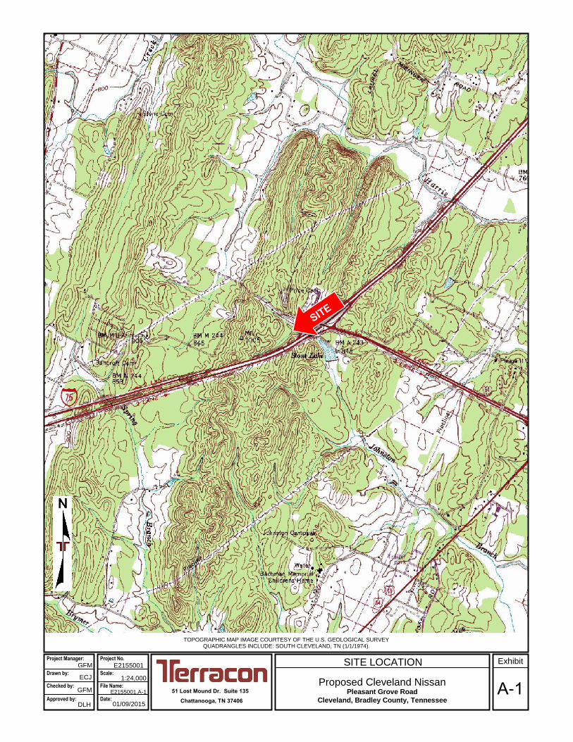
TOPOGRAPHIC MAP IMAGE COURTESY OF THE U.S. GEOLOGICAL SURVEY QUADRANGLES INCLUDE: SOUTH CLEVELAND, TN (1/1/1974).
51 Lost Mound Dr. Suite 135
Chattanooga, TN 37406
E2155001 Project Manager:
Drawn by: Checked by:
Approved by:
SITE LOCATION
Proposed Cleveland Nissan Pleasant Grove Road
Cleveland, Bradley County, Tennessee
ECJ GFM
DLH
1:24,000
E2155001.A-1
01/09/2015 A-1
Exhibit GFM
Project No.
Scale: File Name:
Date:
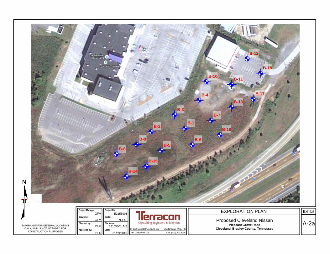
EXPLORATION PLAN
A-2a51 Lost Mound Drive, Suite 135 Chattanooga, TN 37406
PH. (423) 499-6111 FAX. (423) 499-8099
E2155001
01/09/2015
GFM
GFM
DLH
DLH
N.T.S.
Project Manager:
Drawn by:
Checked by:
Approved by:
Project No.
Scale:
File Name:
Date:
Exhibit
E2155001.A-2DIAGRAM IS FOR GENERAL LOCATION
ONLY, AND IS NOT INTENDED FOR
CONSTRUCTION PURPOSES
B-1
Proposed Cleveland NissanPleasant Grove Road
Cleveland, Bradley County, Tennessee
B-2
B-3
B-4
B-5
B-6
B-7
B-8
B-9
B-15
B-14
B-10B-11
B-12
B-18
B-17
B-13
B-16

EXPLORATION PLAN
A-2b51 Lost Mound Drive, Suite 135 Chattanooga, TN 37406
PH. (423) 499-6111 FAX. (423) 499-8099
E2155001
01/09/2015
GFM
GFM
DLH
DLH
N.T.S.
Project Manager:
Drawn by:
Checked by:
Approved by:
Project No.
Scale:
File Name:
Date:
Exhibit
E2155001.A-2DIAGRAM IS FOR GENERAL LOCATION
ONLY, AND IS NOT INTENDED FOR
CONSTRUCTION PURPOSES
B-1
Proposed Cleveland NissanPleasant Grove Road
Cleveland, Bradley County, Tennessee
B-2
B-3
B-4
B-5
B-6
B-7
B-8
B-9
B-15
B-14
B-10B-11
B-12
B-18
B-17
B-13
B-16

Geotechnical Engineering Report
Proposed Cleveland Nissan ■ Cleveland, Tennessee
January 23, 2015 ■ Terracon Project No. E2155001
Responsive ■ Resourceful ■ Reliable Exhibit A-3
Field Exploration Description
The subsurface exploration consisted of drilling and sampling eighteen (18) borings at the site to
depths ranging from about 5 to 32½ feet bgs. The boring locations were laid out by Terracon
personnel. Distances from these locations to the reference features indicated on the attached
diagram are approximate and estimated. Right angles for the boring location measurements were
estimated. The locations of the borings should be considered accurate only to the degree implied
by the means and methods used to define them.
The borings were drilled with an ATV-mounted rotary drill rig using hollow stem augers to advance
the boreholes. Representative soil samples were obtained by the split-barrel sampling procedure.
In this procedure, the number of blows required to advance a standard 2-inch O.D. split-barrel
sampler the last 12 inches of the typical total 18-inch penetration by means of an automatic
140-pound hammer with a free fall of 30 inches, is the standard penetration resistance value (N).
These values are indicted on the borings logs at the depths of occurrence. This value is used to
estimate the in-situ relative density of cohesionless soils and the consistency of cohesive soils.
The sampling depths and penetration distance, plus the standard penetration resistance values,
are shown on the boring logs. The samples were sealed and taken to the laboratory for testing
and classification.
An automatic SPT hammer was used to advance the split-barrel sampler in the borings performed
on this site. A greater efficiency is typically achieved with the automatic hammer compared to the
conventional safety hammer operated with a cathead and rope. Published correlations between
the SPT values and soil properties are based on the lower efficiency cathead and rope method.
This higher efficiency affects the standard penetration resistance blow count (N) value by
increasing the penetration per hammer blow over what would obtained using the cathead and
rope method. The effect of the automatic hammer's efficiency has been considered in the
interpretation and analysis of the subsurface information for this report.
Field logs of each boring were prepared by the drill crew. These logs included visual classifications
of the materials encountered during drilling as well as the driller's interpretation of the subsurface
conditions between samples. Final boring logs included with this report represent an interpretation
of the field logs and include modifications based on laboratory observation and tests of the
samples.
The samples were classified in the laboratory based on visual observation, texture and plasticity.
The descriptions of the soils indicated on the boring logs are in general accordance with the
enclosed General Notes and the Unified Soil Classification System. Estimated group symbols
according to the Unified Soil Classification System are given on the boring logs. A brief description
of this classification system is attached to this report.

0.2
3.0
17.0
TOPSOILSILTY SAND WITH GRAVEL (SM), yellow brown, medium dense
SANDY LEAN CLAY WITH GRAVEL (CL), maroon, stiff to very stiff
SANDY FAT CLAY WITH GRAVEL (CH), reddish-brown, stiff
- yellow brown at 23.5'
4-5-6N=11
6-7-8N=15
2-4-4N=8
3-4-4N=8
3-6-7N=13
3-5-7N=12
4-5-5N=10
3.0(HP)
3.5(HP)
2.25(HP)
3.75(HP)
3.0(HP)
3.0(HP)
2.5(HP)
4316
11
18
15
16
22
21
26-23-3
Hammer Type: AutomaticStratification lines are approximate. In-situ, the transition may be gradual.
LOCATION
DEPTH
Latitude: 35.151417° Longitude: 84.951194°
GR
AP
HIC
LO
G See Exhibit A-2
TH
IS B
OR
ING
LO
G IS
NO
T V
ALI
D IF
SE
PA
RA
TE
D F
RO
M O
RIG
INA
L R
EP
OR
T.
GE
O S
MA
RT
LO
G-N
O W
ELL
E21
5500
1. C
LEV
ELA
ND
NIS
SA
N.G
PJ
TE
RR
AC
ON
2012
.GD
T
1/20
/15
131 Pleasant Grove Road Cleveland, TNSITE:
Page 1 of 2
Advancement Method:2 1/4" Hollow Stem Auger
Abandonment Method:Borings backfilled with soil cuttings upon completion.
51 Lost Mound Drive, Suite 135Chattanooga, Tennessee
Notes:
Project No.: E2155001
Drill Rig: DR0009
Boring Started: 1/8/2015
BORING LOG NO. B-1Sonic AutomotiveCLIENT:Charlotte, North Carolina
Driller: C. Penton
Boring Completed: 1/8/2015
Exhibit: A-4
See Exhibit A-3 for description of fieldprocedures.See Appendix B for description of laboratoryprocedures and additional data (if any).
See Appendix C for explanation of symbols andabbreviations.
PROJECT: Cleveland Nissan
FIE
LD T
ES
TR
ES
ULT
S
LAB
OR
AT
OR
YT
OR
VA
NE
/HP
(ts
f)
PE
RC
EN
T F
INE
S
WA
TE
RC
ON
TE
NT
(%
)
ATTERBERGLIMITS
LL-PL-PI
SA
MP
LE T
YP
E
WA
TE
R L
EV
EL
OB
SE
RV
AT
ION
S
DE
PT
H (
Ft.)
5
10
15
20
25
Water Encountered at 30'WATER LEVEL OBSERVATIONS
32.5
SANDY FAT CLAY WITH GRAVEL (CH), reddish-brown, stiff (continued)
- maroon at 28.5'
Auger Refusal at 32.5 Feet
4-6-3N=9
1.75(HP) 17
Hammer Type: AutomaticStratification lines are approximate. In-situ, the transition may be gradual.
LOCATION
DEPTH
Latitude: 35.151417° Longitude: 84.951194°
GR
AP
HIC
LO
G See Exhibit A-2
TH
IS B
OR
ING
LO
G IS
NO
T V
ALI
D IF
SE
PA
RA
TE
D F
RO
M O
RIG
INA
L R
EP
OR
T.
GE
O S
MA
RT
LO
G-N
O W
ELL
E21
5500
1. C
LEV
ELA
ND
NIS
SA
N.G
PJ
TE
RR
AC
ON
2012
.GD
T
1/20
/15
131 Pleasant Grove Road Cleveland, TNSITE:
Page 2 of 2
Advancement Method:2 1/4" Hollow Stem Auger
Abandonment Method:Borings backfilled with soil cuttings upon completion.
51 Lost Mound Drive, Suite 135Chattanooga, Tennessee
Notes:
Project No.: E2155001
Drill Rig: DR0009
Boring Started: 1/8/2015
BORING LOG NO. B-1Sonic AutomotiveCLIENT:Charlotte, North Carolina
Driller: C. Penton
Boring Completed: 1/8/2015
Exhibit: A-4
See Exhibit A-3 for description of fieldprocedures.See Appendix B for description of laboratoryprocedures and additional data (if any).
See Appendix C for explanation of symbols andabbreviations.
PROJECT: Cleveland Nissan
FIE
LD T
ES
TR
ES
ULT
S
LAB
OR
AT
OR
YT
OR
VA
NE
/HP
(ts
f)
PE
RC
EN
T F
INE
S
WA
TE
RC
ON
TE
NT
(%
)
ATTERBERGLIMITS
LL-PL-PI
SA
MP
LE T
YP
E
WA
TE
R L
EV
EL
OB
SE
RV
AT
ION
S
DE
PT
H (
Ft.)
30
Water Encountered at 30'WATER LEVEL OBSERVATIONS

0.2
3.0
17.0
23.0
25.0
TOPSOILGRAVELLY LEAN CLAY WITH SAND (CL), yellow brown, stiff
SANDY LEAN CLAY WITH GRAVEL (CL), maroon, stiff to very stiff
SANDY FAT CLAY WITH GRAVEL (CH), reddish-brown, stiff to very stiff
FAT CLAY WITH SAND (CH), trace gravel, reddish-brown, stiff
Boring Terminated at 25 Feet
3-4-8N=12
8-10-9N=19
4-3-7N=10
4-5-6N=11
8-9-11N=20
6-6-7N=13
4-4-4N=8
4.5(HP)
2.5(HP)
4.5(HP)
4.5(HP)
3.5(HP)
2.5(HP)
11
13
17
17
17
18
22
Hammer Type: AutomaticStratification lines are approximate. In-situ, the transition may be gradual.
LOCATION
DEPTH
Latitude: 35.151417° Longitude: 84.951556°
GR
AP
HIC
LO
G See Exhibit A-2
TH
IS B
OR
ING
LO
G IS
NO
T V
ALI
D IF
SE
PA
RA
TE
D F
RO
M O
RIG
INA
L R
EP
OR
T.
GE
O S
MA
RT
LO
G-N
O W
ELL
E21
5500
1. C
LEV
ELA
ND
NIS
SA
N.G
PJ
TE
RR
AC
ON
2012
.GD
T
1/20
/15
131 Pleasant Grove Road Cleveland, TNSITE:
Page 1 of 1
Advancement Method:2 1/4" Hollow Stem Auger
Abandonment Method:Borings backfilled with soil cuttings upon completion.
51 Lost Mound Drive, Suite 135Chattanooga, Tennessee
Notes:
Project No.: E2155001
Drill Rig: DR0009
Boring Started: 1/8/2015
BORING LOG NO. B-2Sonic AutomotiveCLIENT:Charlotte, North Carolina
Driller: C. Penton
Boring Completed: 1/8/2015
Exhibit: A-5
See Exhibit A-3 for description of fieldprocedures.See Appendix B for description of laboratoryprocedures and additional data (if any).
See Appendix C for explanation of symbols andabbreviations.
PROJECT: Cleveland Nissan
FIE
LD T
ES
TR
ES
ULT
S
LAB
OR
AT
OR
YT
OR
VA
NE
/HP
(ts
f)
PE
RC
EN
T F
INE
S
WA
TE
RC
ON
TE
NT
(%
)
ATTERBERGLIMITS
LL-PL-PI
SA
MP
LE T
YP
E
WA
TE
R L
EV
EL
OB
SE
RV
AT
ION
S
DE
PT
H (
Ft.)
5
10
15
20
25
No free water observedWATER LEVEL OBSERVATIONS

0.2
3.0
5.0
12.0
25.0
TOPSOILSANDY SILT WITH GRAVEL (ML), grayish-brown, stiff to very stiff
SANDY LEAN CLAY (CL), trace gravel, maroon, stiff to very stiff
SANDY LEAN CLAY WITH GRAVEL (CL), maroon, stiff to very stiff
SANDY FAT CLAY WITH GRAVEL (CH), brown, stiff
Boring Terminated at 25 Feet
4-6-6N=12
3-8-9N=17
2-7-10N=17
4-5-7N=12
2-3-6N=9
4-4-8N=12
2-3-6N=9
4.5(HP)
2.0(HP)
3.25(HP)
3.25(HP)
3.5(HP)
2.5(HP)
4.0(HP)
Hammer Type: AutomaticStratification lines are approximate. In-situ, the transition may be gradual.
LOCATION
DEPTH
Latitude: 35.151528° Longitude: 84.95125°
GR
AP
HIC
LO
G See Exhibit A-2
TH
IS B
OR
ING
LO
G IS
NO
T V
ALI
D IF
SE
PA
RA
TE
D F
RO
M O
RIG
INA
L R
EP
OR
T.
GE
O S
MA
RT
LO
G-N
O W
ELL
E21
5500
1. C
LEV
ELA
ND
NIS
SA
N.G
PJ
TE
RR
AC
ON
2012
.GD
T
1/20
/15
131 Pleasant Grove Road Cleveland, TNSITE:
Page 1 of 1
Advancement Method:2 1/4" Hollow Stem Auger
Abandonment Method:Borings backfilled with soil cuttings upon completion.
51 Lost Mound Drive, Suite 135Chattanooga, Tennessee
Notes:
Project No.: E2155001
Drill Rig: DR0009
Boring Started: 1/8/2015
BORING LOG NO. B-3Sonic AutomotiveCLIENT:Charlotte, North Carolina
Driller: C. Penton
Boring Completed: 1/8/2015
Exhibit: A-6
See Exhibit A-3 for description of fieldprocedures.See Appendix B for description of laboratoryprocedures and additional data (if any).
See Appendix C for explanation of symbols andabbreviations.
PROJECT: Cleveland Nissan
FIE
LD T
ES
TR
ES
ULT
S
LAB
OR
AT
OR
YT
OR
VA
NE
/HP
(ts
f)
PE
RC
EN
T F
INE
S
WA
TE
RC
ON
TE
NT
(%
)
ATTERBERGLIMITS
LL-PL-PI
SA
MP
LE T
YP
E
WA
TE
R L
EV
EL
OB
SE
RV
AT
ION
S
DE
PT
H (
Ft.)
5
10
15
20
25
No free water observedWATER LEVEL OBSERVATIONS

0.3
8.0
12.0
22.0
25.0
TOPSOIL, trace gravelCLAYEY GRAVEL WITH SAND (GC), maroon and brown, medium dense
SANDY SILT (ML), trace gravel, yellow brown and olive-brown mottled,very stiff
SANDY SILT WITH GRAVEL (ML), maroon mottled, stiff to very stiff
SANDY FAT CLAY (CH), trace gravel, maroon mottled, stiff to very stiff
Boring Terminated at 25 Feet
8-12-11N=23
6-8-8N=16
5-6-9N=15
10-7-9N=16
4-7-7N=14
3-5-7N=12
3-4-5N=9
3.75(HP)
4.0(HP)
3.25(HP)
3.25(HP)
2.25(HP)
3.25(HP)
3.0(HP)
359
14
17
15
14
22
20
28-20-8
Hammer Type: AutomaticStratification lines are approximate. In-situ, the transition may be gradual.
LOCATION
DEPTH
Latitude: 35.151722° Longitude: 84.950944°
GR
AP
HIC
LO
G See Exhibit A-2
TH
IS B
OR
ING
LO
G IS
NO
T V
ALI
D IF
SE
PA
RA
TE
D F
RO
M O
RIG
INA
L R
EP
OR
T.
GE
O S
MA
RT
LO
G-N
O W
ELL
E21
5500
1. C
LEV
ELA
ND
NIS
SA
N.G
PJ
TE
RR
AC
ON
2012
.GD
T
1/20
/15
131 Pleasant Grove Road Cleveland, TNSITE:
Page 1 of 1
Advancement Method:2 1/4" Hollow Stem Auger
Abandonment Method:Borings backfilled with soil cuttings upon completion.
51 Lost Mound Drive, Suite 135Chattanooga, Tennessee
Notes:
Project No.: E2155001
Drill Rig: DR0009
Boring Started: 1/8/2015
BORING LOG NO. B-4Sonic AutomotiveCLIENT:Charlotte, North Carolina
Driller: C. Penton
Boring Completed: 1/8/2015
Exhibit: A-7
See Exhibit A-3 for description of fieldprocedures.See Appendix B for description of laboratoryprocedures and additional data (if any).
See Appendix C for explanation of symbols andabbreviations.
PROJECT: Cleveland Nissan
FIE
LD T
ES
TR
ES
ULT
S
LAB
OR
AT
OR
YT
OR
VA
NE
/HP
(ts
f)
PE
RC
EN
T F
INE
S
WA
TE
RC
ON
TE
NT
(%
)
ATTERBERGLIMITS
LL-PL-PI
SA
MP
LE T
YP
E
WA
TE
R L
EV
EL
OB
SE
RV
AT
ION
S
DE
PT
H (
Ft.)
5
10
15
20
25
No free water observedWATER LEVEL OBSERVATIONS

0.2
3.0
22.0
25.0
TOPSOILSILTY GRAVEL WITH SAND (GM), yellow brown, medium dense
SANDY LEAN CLAY WITH GRAVEL (CL), brown mottled, very stiff
- maroon at 8.5'
GRAVELLY SILT WITH SAND (ML), brown and gray, stiff
Boring Terminated at 25 Feet
4-6-8N=14
7-7-8N=15
6-7-9N=16
5-6-12N=18
11-12-13N=25
10-9-6N=15
6-5-5N=10
4.0(HP)
3.0(HP)
3.5(HP)
4.25(HP)
4.5(HP)
4.5(HP)
3811
18
13
16
12
13
8
29-23-6
Hammer Type: AutomaticStratification lines are approximate. In-situ, the transition may be gradual.
LOCATION
DEPTH
Latitude: 35.15125° Longitude: 84.9515°
GR
AP
HIC
LO
G See Exhibit A-2
TH
IS B
OR
ING
LO
G IS
NO
T V
ALI
D IF
SE
PA
RA
TE
D F
RO
M O
RIG
INA
L R
EP
OR
T.
GE
O S
MA
RT
LO
G-N
O W
ELL
E21
5500
1. C
LEV
ELA
ND
NIS
SA
N.G
PJ
TE
RR
AC
ON
2012
.GD
T
1/20
/15
131 Pleasant Grove Road Cleveland, TNSITE:
Page 1 of 1
Advancement Method:2 1/4" Hollow Stem Auger
Abandonment Method:Borings backfilled with soil cuttings upon completion.
51 Lost Mound Drive, Suite 135Chattanooga, Tennessee
Notes:
Project No.: E2155001
Drill Rig: DR0009
Boring Started: 1/8/2015
BORING LOG NO. B-5Sonic AutomotiveCLIENT:Charlotte, North Carolina
Driller: C. Penton
Boring Completed: 1/8/2015
Exhibit: A-8
See Exhibit A-3 for description of fieldprocedures.See Appendix B for description of laboratoryprocedures and additional data (if any).
See Appendix C for explanation of symbols andabbreviations.
PROJECT: Cleveland Nissan
FIE
LD T
ES
TR
ES
ULT
S
LAB
OR
AT
OR
YT
OR
VA
NE
/HP
(ts
f)
PE
RC
EN
T F
INE
S
WA
TE
RC
ON
TE
NT
(%
)
ATTERBERGLIMITS
LL-PL-PI
SA
MP
LE T
YP
E
WA
TE
R L
EV
EL
OB
SE
RV
AT
ION
S
DE
PT
H (
Ft.)
5
10
15
20
25
No free water observedWATER LEVEL OBSERVATIONS
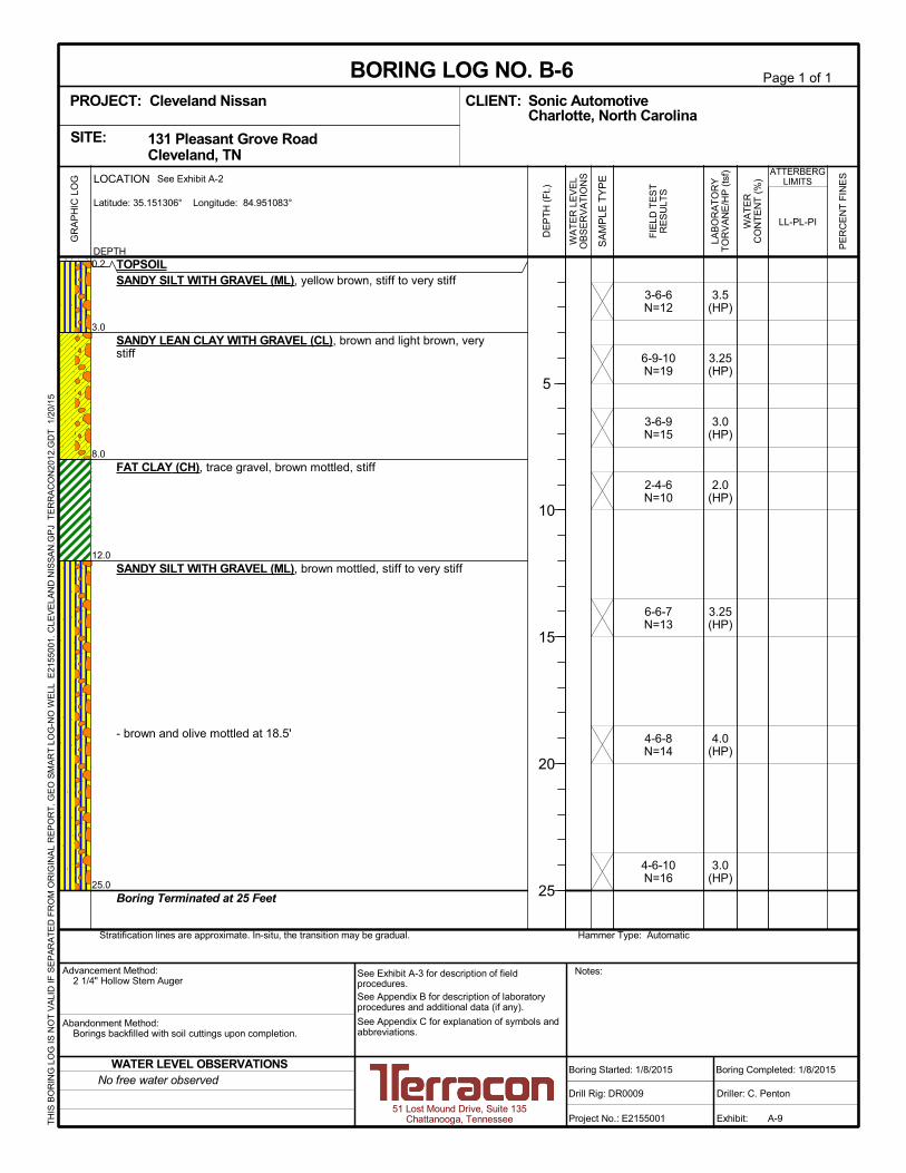
0.2
3.0
8.0
12.0
25.0
TOPSOILSANDY SILT WITH GRAVEL (ML), yellow brown, stiff to very stiff
SANDY LEAN CLAY WITH GRAVEL (CL), brown and light brown, verystiff
FAT CLAY (CH), trace gravel, brown mottled, stiff
SANDY SILT WITH GRAVEL (ML), brown mottled, stiff to very stiff
- brown and olive mottled at 18.5'
Boring Terminated at 25 Feet
3-6-6N=12
6-9-10N=19
3-6-9N=15
2-4-6N=10
6-6-7N=13
4-6-8N=14
4-6-10N=16
3.5(HP)
3.25(HP)
3.0(HP)
2.0(HP)
3.25(HP)
4.0(HP)
3.0(HP)
Hammer Type: AutomaticStratification lines are approximate. In-situ, the transition may be gradual.
LOCATION
DEPTH
Latitude: 35.151306° Longitude: 84.951083°
GR
AP
HIC
LO
G See Exhibit A-2
TH
IS B
OR
ING
LO
G IS
NO
T V
ALI
D IF
SE
PA
RA
TE
D F
RO
M O
RIG
INA
L R
EP
OR
T.
GE
O S
MA
RT
LO
G-N
O W
ELL
E21
5500
1. C
LEV
ELA
ND
NIS
SA
N.G
PJ
TE
RR
AC
ON
2012
.GD
T
1/20
/15
131 Pleasant Grove Road Cleveland, TNSITE:
Page 1 of 1
Advancement Method:2 1/4" Hollow Stem Auger
Abandonment Method:Borings backfilled with soil cuttings upon completion.
51 Lost Mound Drive, Suite 135Chattanooga, Tennessee
Notes:
Project No.: E2155001
Drill Rig: DR0009
Boring Started: 1/8/2015
BORING LOG NO. B-6Sonic AutomotiveCLIENT:Charlotte, North Carolina
Driller: C. Penton
Boring Completed: 1/8/2015
Exhibit: A-9
See Exhibit A-3 for description of fieldprocedures.See Appendix B for description of laboratoryprocedures and additional data (if any).
See Appendix C for explanation of symbols andabbreviations.
PROJECT: Cleveland Nissan
FIE
LD T
ES
TR
ES
ULT
S
LAB
OR
AT
OR
YT
OR
VA
NE
/HP
(ts
f)
PE
RC
EN
T F
INE
S
WA
TE
RC
ON
TE
NT
(%
)
ATTERBERGLIMITS
LL-PL-PI
SA
MP
LE T
YP
E
WA
TE
R L
EV
EL
OB
SE
RV
AT
ION
S
DE
PT
H (
Ft.)
5
10
15
20
25
No free water observedWATER LEVEL OBSERVATIONS
0.2
5.0
17.0
25.0
TOPSOILSANDY SILT (ML), trace gravel, reddish-brown and yellow brown, stiff tovery stiff
SANDY LEAN CLAY WITH GRAVEL (CL), maroon mottled, stiff to verystiff
- brown and gray mottled at 13.5'
SANDY SILT WITH GRAVEL (ML), maroon mottled and brown, stiff tovery stiff
Boring Terminated at 25 Feet
4-6-8N=14
5-7-8N=15
4-6-9N=15
3-3-5N=8
3-7-11N=18
6-6-7N=13
4-5-8N=13
3.75(HP)
2.5(HP)
3.5(HP)
2.5(HP)
4.5(HP)
4.5(HP)
14
13
17
17
12
14
14
Hammer Type: AutomaticStratification lines are approximate. In-situ, the transition may be gradual.
LOCATION
DEPTH
Latitude: 35.151528° Longitude: 84.950778°
GR
AP
HIC
LO
G See Exhibit A-2
TH
IS B
OR
ING
LO
G IS
NO
T V
ALI
D IF
SE
PA
RA
TE
D F
RO
M O
RIG
INA
L R
EP
OR
T.
GE
O S
MA
RT
LO
G-N
O W
ELL
E21
5500
1. C
LEV
ELA
ND
NIS
SA
N.G
PJ
TE
RR
AC
ON
2012
.GD
T
1/20
/15
131 Pleasant Grove Road Cleveland, TNSITE:
Page 1 of 1
Advancement Method:2 1/4" Hollow Stem Auger
Abandonment Method:Borings backfilled with soil cuttings upon completion.
51 Lost Mound Drive, Suite 135Chattanooga, Tennessee
Notes:
Project No.: E2155001
Drill Rig: DR0009
Boring Started: 1/8/2015
BORING LOG NO. B-7Sonic AutomotiveCLIENT:Charlotte, North Carolina
Driller: C. Penton
Boring Completed: 1/8/2015
Exhibit: A-10
See Exhibit A-3 for description of fieldprocedures.See Appendix B for description of laboratoryprocedures and additional data (if any).
See Appendix C for explanation of symbols andabbreviations.
PROJECT: Cleveland Nissan
FIE
LD T
ES
TR
ES
ULT
S
LAB
OR
AT
OR
YT
OR
VA
NE
/HP
(ts
f)
PE
RC
EN
T F
INE
S
WA
TE
RC
ON
TE
NT
(%
)
ATTERBERGLIMITS
LL-PL-PI
SA
MP
LE T
YP
E
WA
TE
R L
EV
EL
OB
SE
RV
AT
ION
S
DE
PT
H (
Ft.)
5
10
15
20
25
No free water observedWATER LEVEL OBSERVATIONS

0.2
3.0
5.0
TOPSOILFILL - SANDY LEAN CLAY , yellow brown mottled
LEAN CLAY WITH SAND (CL), yellowish-brown, very stiff
Boring Terminated at 5 Feet
2-2-7N=9
6-8-10N=18
2.5(HP)
3.75(HP)
19
19
Hammer Type: AutomaticStratification lines are approximate. In-situ, the transition may be gradual.
LOCATION
DEPTH
Latitude: 35.151194° Longitude: 84.952°
GR
AP
HIC
LO
G See Exhibit A-2
TH
IS B
OR
ING
LO
G IS
NO
T V
ALI
D IF
SE
PA
RA
TE
D F
RO
M O
RIG
INA
L R
EP
OR
T.
GE
O S
MA
RT
LO
G-N
O W
ELL
E21
5500
1. C
LEV
ELA
ND
NIS
SA
N.G
PJ
TE
RR
AC
ON
2012
.GD
T
1/20
/15
131 Pleasant Grove Road Cleveland, TNSITE:
Page 1 of 1
Advancement Method:2 1/4" Hollow Stem Auger
Abandonment Method:Borings backfilled with soil cuttings upon completion.
51 Lost Mound Drive, Suite 135Chattanooga, Tennessee
Notes:
Project No.: E2155001
Drill Rig: DR0009
Boring Started: 1/8/2015
BORING LOG NO. B-8Sonic AutomotiveCLIENT:Charlotte, North Carolina
Driller: C. Penton
Boring Completed: 1/8/2015
Exhibit: A-11
See Exhibit A-3 for description of fieldprocedures.See Appendix B for description of laboratoryprocedures and additional data (if any).
See Appendix C for explanation of symbols andabbreviations.
PROJECT: Cleveland Nissan
FIE
LD T
ES
TR
ES
ULT
S
LAB
OR
AT
OR
YT
OR
VA
NE
/HP
(ts
f)
PE
RC
EN
T F
INE
S
WA
TE
RC
ON
TE
NT
(%
)
ATTERBERGLIMITS
LL-PL-PI
SA
MP
LE T
YP
E
WA
TE
R L
EV
EL
OB
SE
RV
AT
ION
S
DE
PT
H (
Ft.)
5
No free water observedWATER LEVEL OBSERVATIONS

0.2
5.0
TOPSOILSANDY LEAN CLAY WITH GRAVEL (CL), yellow brown and gray mottled,stiff to very stiff
Boring Terminated at 5 Feet
3-5-7N=12
5-7-13N=20
3.75(HP)
4.75(HP)
Hammer Type: AutomaticStratification lines are approximate. In-situ, the transition may be gradual.
LOCATION
DEPTH
Latitude: 35.151278° Longitude: 84.951722°
GR
AP
HIC
LO
G See Exhibit A-2
TH
IS B
OR
ING
LO
G IS
NO
T V
ALI
D IF
SE
PA
RA
TE
D F
RO
M O
RIG
INA
L R
EP
OR
T.
GE
O S
MA
RT
LO
G-N
O W
ELL
E21
5500
1. C
LEV
ELA
ND
NIS
SA
N.G
PJ
TE
RR
AC
ON
2012
.GD
T
1/20
/15
131 Pleasant Grove Road Cleveland, TNSITE:
Page 1 of 1
Advancement Method:2 1/4" Hollow Stem Auger
Abandonment Method:Borings backfilled with soil cuttings upon completion.
51 Lost Mound Drive, Suite 135Chattanooga, Tennessee
Notes:
Project No.: E2155001
Drill Rig: DR0009
Boring Started: 1/8/2015
BORING LOG NO. B-9Sonic AutomotiveCLIENT:Charlotte, North Carolina
Driller: C. Penton
Boring Completed: 1/8/2015
Exhibit: A-12
See Exhibit A-3 for description of fieldprocedures.See Appendix B for description of laboratoryprocedures and additional data (if any).
See Appendix C for explanation of symbols andabbreviations.
PROJECT: Cleveland Nissan
FIE
LD T
ES
TR
ES
ULT
S
LAB
OR
AT
OR
YT
OR
VA
NE
/HP
(ts
f)
PE
RC
EN
T F
INE
S
WA
TE
RC
ON
TE
NT
(%
)
ATTERBERGLIMITS
LL-PL-PI
SA
MP
LE T
YP
E
WA
TE
R L
EV
EL
OB
SE
RV
AT
ION
S
DE
PT
H (
Ft.)
5
No free water observedWATER LEVEL OBSERVATIONS

0.2
5.0
GRAVELSANDY LEAN CLAY (CL), trace gravel, yellow brown mottled, stiff to verystiff
- maroon mottled at 3.5'
Boring Terminated at 5 Feet
3-5-6N=11
5-7-8N=15
3.5(HP)
1.75(HP)
Hammer Type: AutomaticStratification lines are approximate. In-situ, the transition may be gradual.
LOCATION
DEPTH
Latitude: 35.151861° Longitude: 84.950681°
GR
AP
HIC
LO
G See Exhibit A-2
TH
IS B
OR
ING
LO
G IS
NO
T V
ALI
D IF
SE
PA
RA
TE
D F
RO
M O
RIG
INA
L R
EP
OR
T.
GE
O S
MA
RT
LO
G-N
O W
ELL
E21
5500
1. C
LEV
ELA
ND
NIS
SA
N.G
PJ
TE
RR
AC
ON
2012
.GD
T
1/20
/15
131 Pleasant Grove Road Cleveland, TNSITE:
Page 1 of 1
Advancement Method:2 1/4" Hollow Stem Auger
Abandonment Method:Borings backfilled with soil cuttings upon completion.
51 Lost Mound Drive, Suite 135Chattanooga, Tennessee
Notes:
Project No.: E2155001
Drill Rig: DR0009
Boring Started: 1/8/2015
BORING LOG NO. B-10Sonic AutomotiveCLIENT:Charlotte, North Carolina
Driller: C. Penton
Boring Completed: 1/8/2015
Exhibit: A-13
See Exhibit A-3 for description of fieldprocedures.See Appendix B for description of laboratoryprocedures and additional data (if any).
See Appendix C for explanation of symbols andabbreviations.
PROJECT: Cleveland Nissan
FIE
LD T
ES
TR
ES
ULT
S
LAB
OR
AT
OR
YT
OR
VA
NE
/HP
(ts
f)
PE
RC
EN
T F
INE
S
WA
TE
RC
ON
TE
NT
(%
)
ATTERBERGLIMITS
LL-PL-PI
SA
MP
LE T
YP
E
WA
TE
R L
EV
EL
OB
SE
RV
AT
ION
S
DE
PT
H (
Ft.)
5
No free water observedWATER LEVEL OBSERVATIONS

0.3
3.0
5.0
TOPSOIL, trace gravelFILL - SANDY LEAN CLAY , maroon, trace shale fragments
SANDY LEAN CLAY WITH GRAVEL (CL), dark maroon, very stiff, shalefragments
Boring Terminated at 5 Feet
3-3-6N=9
8-9-13N=22
3.75(HP)
4.25(HP)
Hammer Type: AutomaticStratification lines are approximate. In-situ, the transition may be gradual.
LOCATION
DEPTH
Latitude: 35.151944° Longitude: 84.950528°
GR
AP
HIC
LO
G See Exhibit A-2
TH
IS B
OR
ING
LO
G IS
NO
T V
ALI
D IF
SE
PA
RA
TE
D F
RO
M O
RIG
INA
L R
EP
OR
T.
GE
O S
MA
RT
LO
G-N
O W
ELL
E21
5500
1. C
LEV
ELA
ND
NIS
SA
N.G
PJ
TE
RR
AC
ON
2012
.GD
T
1/20
/15
131 Pleasant Grove Road Cleveland, TNSITE:
Page 1 of 1
Advancement Method:2 1/4" Hollow Stem Auger
Abandonment Method:Borings backfilled with soil cuttings upon completion.
51 Lost Mound Drive, Suite 135Chattanooga, Tennessee
Notes:
Project No.: E2155001
Drill Rig: DR0009
Boring Started: 1/8/2015
BORING LOG NO. B-11Sonic AutomotiveCLIENT:Charlotte, North Carolina
Driller: C. Penton
Boring Completed: 1/8/2015
Exhibit: A-14
See Exhibit A-3 for description of fieldprocedures.See Appendix B for description of laboratoryprocedures and additional data (if any).
See Appendix C for explanation of symbols andabbreviations.
PROJECT: Cleveland Nissan
FIE
LD T
ES
TR
ES
ULT
S
LAB
OR
AT
OR
YT
OR
VA
NE
/HP
(ts
f)
PE
RC
EN
T F
INE
S
WA
TE
RC
ON
TE
NT
(%
)
ATTERBERGLIMITS
LL-PL-PI
SA
MP
LE T
YP
E
WA
TE
R L
EV
EL
OB
SE
RV
AT
ION
S
DE
PT
H (
Ft.)
5
No free water observedWATER LEVEL OBSERVATIONS

0.20.4
3.0
5.0
ASPHALT, 2 inchesBASESTONE, 3 inchesFILL - CLAYEY SAND WITH GRAVEL , yellow brown
SANDY LEAN CLAY WITH GRAVEL (CL), yellow brown to olive-brownmottled, stiff
Boring Terminated at 5 Feet
8-9-9N=18
6-4-7N=11
3.25(HP)
4.25(HP)
4216
15
29-21-8
Hammer Type: AutomaticStratification lines are approximate. In-situ, the transition may be gradual.
LOCATION
DEPTH
Latitude: 35.152167° Longitude: 84.950306°
GR
AP
HIC
LO
G See Exhibit A-2
TH
IS B
OR
ING
LO
G IS
NO
T V
ALI
D IF
SE
PA
RA
TE
D F
RO
M O
RIG
INA
L R
EP
OR
T.
GE
O S
MA
RT
LO
G-N
O W
ELL
E21
5500
1. C
LEV
ELA
ND
NIS
SA
N.G
PJ
TE
RR
AC
ON
2012
.GD
T
1/20
/15
131 Pleasant Grove Road Cleveland, TNSITE:
Page 1 of 1
Advancement Method:2 1/4" Hollow Stem Auger
Abandonment Method:Borings backfilled with soil cuttings upon completion.Sealed with bituminous cold patch at surface.
51 Lost Mound Drive, Suite 135Chattanooga, Tennessee
Notes:
Project No.: E2155001
Drill Rig: DR0009
Boring Started: 1/8/2015
BORING LOG NO. B-12Sonic AutomotiveCLIENT:Charlotte, North Carolina
Driller: C. Penton
Boring Completed: 1/8/2015
Exhibit: A-15
See Exhibit A-3 for description of fieldprocedures.See Appendix B for description of laboratoryprocedures and additional data (if any).
See Appendix C for explanation of symbols andabbreviations.
PROJECT: Cleveland Nissan
FIE
LD T
ES
TR
ES
ULT
S
LAB
OR
AT
OR
YT
OR
VA
NE
/HP
(ts
f)
PE
RC
EN
T F
INE
S
WA
TE
RC
ON
TE
NT
(%
)
ATTERBERGLIMITS
LL-PL-PI
SA
MP
LE T
YP
E
WA
TE
R L
EV
EL
OB
SE
RV
AT
ION
S
DE
PT
H (
Ft.)
5
No free water observedWATER LEVEL OBSERVATIONS

0.3
5.0
TOPSOILSANDY LEAN CLAY WITH GRAVEL (CL), brown mottled, stiff to very stiff
Boring Terminated at 5 Feet
3-5-7N=12
5-6-7N=13
3.5(HP)
4.0(HP)
Hammer Type: AutomaticStratification lines are approximate. In-situ, the transition may be gradual.
LOCATION
DEPTH
Latitude: 35.151667° Longitude: 84.950556°
GR
AP
HIC
LO
G See Exhibit A-2
TH
IS B
OR
ING
LO
G IS
NO
T V
ALI
D IF
SE
PA
RA
TE
D F
RO
M O
RIG
INA
L R
EP
OR
T.
GE
O S
MA
RT
LO
G-N
O W
ELL
E21
5500
1. C
LEV
ELA
ND
NIS
SA
N.G
PJ
TE
RR
AC
ON
2012
.GD
T
1/20
/15
131 Pleasant Grove Road Cleveland, TNSITE:
Page 1 of 1
Advancement Method:2 1/4" Hollow Stem Auger
Abandonment Method:Borings backfilled with soil cuttings upon completion.
51 Lost Mound Drive, Suite 135Chattanooga, Tennessee
Notes:
Project No.: E2155001
Drill Rig: DR0009
Boring Started: 1/8/2015
BORING LOG NO. B-13Sonic AutomotiveCLIENT:Charlotte, North Carolina
Driller: C. Penton
Boring Completed: 1/8/2015
Exhibit: A-16
See Exhibit A-3 for description of fieldprocedures.See Appendix B for description of laboratoryprocedures and additional data (if any).
See Appendix C for explanation of symbols andabbreviations.
PROJECT: Cleveland Nissan
FIE
LD T
ES
TR
ES
ULT
S
LAB
OR
AT
OR
YT
OR
VA
NE
/HP
(ts
f)
PE
RC
EN
T F
INE
S
WA
TE
RC
ON
TE
NT
(%
)
ATTERBERGLIMITS
LL-PL-PI
SA
MP
LE T
YP
E
WA
TE
R L
EV
EL
OB
SE
RV
AT
ION
S
DE
PT
H (
Ft.)
5
No free water observedWATER LEVEL OBSERVATIONS
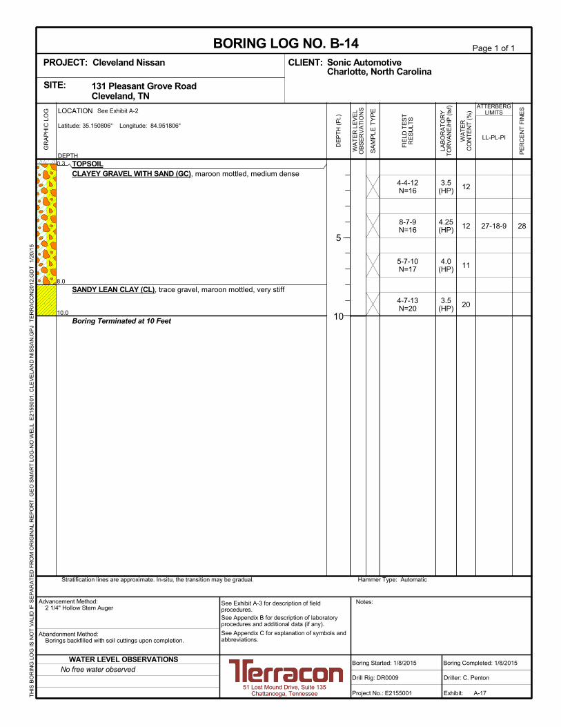
0.3
8.0
10.0
TOPSOILCLAYEY GRAVEL WITH SAND (GC), maroon mottled, medium dense
SANDY LEAN CLAY (CL), trace gravel, maroon mottled, very stiff
Boring Terminated at 10 Feet
4-4-12N=16
8-7-9N=16
5-7-10N=17
4-7-13N=20
3.5(HP)
4.25(HP)
4.0(HP)
3.5(HP)
28
12
12
11
20
27-18-9
Hammer Type: AutomaticStratification lines are approximate. In-situ, the transition may be gradual.
LOCATION
DEPTH
Latitude: 35.150806° Longitude: 84.951806°
GR
AP
HIC
LO
G See Exhibit A-2
TH
IS B
OR
ING
LO
G IS
NO
T V
ALI
D IF
SE
PA
RA
TE
D F
RO
M O
RIG
INA
L R
EP
OR
T.
GE
O S
MA
RT
LO
G-N
O W
ELL
E21
5500
1. C
LEV
ELA
ND
NIS
SA
N.G
PJ
TE
RR
AC
ON
2012
.GD
T
1/20
/15
131 Pleasant Grove Road Cleveland, TNSITE:
Page 1 of 1
Advancement Method:2 1/4" Hollow Stem Auger
Abandonment Method:Borings backfilled with soil cuttings upon completion.
51 Lost Mound Drive, Suite 135Chattanooga, Tennessee
Notes:
Project No.: E2155001
Drill Rig: DR0009
Boring Started: 1/8/2015
BORING LOG NO. B-14Sonic AutomotiveCLIENT:Charlotte, North Carolina
Driller: C. Penton
Boring Completed: 1/8/2015
Exhibit: A-17
See Exhibit A-3 for description of fieldprocedures.See Appendix B for description of laboratoryprocedures and additional data (if any).
See Appendix C for explanation of symbols andabbreviations.
PROJECT: Cleveland Nissan
FIE
LD T
ES
TR
ES
ULT
S
LAB
OR
AT
OR
YT
OR
VA
NE
/HP
(ts
f)
PE
RC
EN
T F
INE
S
WA
TE
RC
ON
TE
NT
(%
)
ATTERBERGLIMITS
LL-PL-PI
SA
MP
LE T
YP
E
WA
TE
R L
EV
EL
OB
SE
RV
AT
ION
S
DE
PT
H (
Ft.)
5
10
No free water observedWATER LEVEL OBSERVATIONS

0.3
3.0
10.0
TOPSOILLEAN CLAY WITH GRAVEL (CL), trace sand, maroon mottled, stiff tovery stiff
SANDY LEAN CLAY WITH GRAVEL (CL), yellow brown mottled, stiff tovery stiff
- maroon at 8.5'
Boring Terminated at 10 Feet
9-5-7N=12
4-7-7N=14
5-7-8N=15
6-9-11N=20
4.5(HP)
3.25(HP)
3.25(HP)
3.5(HP)
Hammer Type: AutomaticStratification lines are approximate. In-situ, the transition may be gradual.
LOCATION
DEPTH
Latitude: 35.150972° Longitude: 84.951472°
GR
AP
HIC
LO
G See Exhibit A-2
TH
IS B
OR
ING
LO
G IS
NO
T V
ALI
D IF
SE
PA
RA
TE
D F
RO
M O
RIG
INA
L R
EP
OR
T.
GE
O S
MA
RT
LO
G-N
O W
ELL
E21
5500
1. C
LEV
ELA
ND
NIS
SA
N.G
PJ
TE
RR
AC
ON
2012
.GD
T
1/20
/15
131 Pleasant Grove Road Cleveland, TNSITE:
Page 1 of 1
Advancement Method:2 1/4" Hollow Stem Auger
Abandonment Method:Borings backfilled with soil cuttings upon completion.
51 Lost Mound Drive, Suite 135Chattanooga, Tennessee
Notes:
Project No.: E2155001
Drill Rig: DR0009
Boring Started: 1/8/2015
BORING LOG NO. B-15Sonic AutomotiveCLIENT:Charlotte, North Carolina
Driller: C. Penton
Boring Completed: 1/8/2015
Exhibit: A-18
See Exhibit A-3 for description of fieldprocedures.See Appendix B for description of laboratoryprocedures and additional data (if any).
See Appendix C for explanation of symbols andabbreviations.
PROJECT: Cleveland Nissan
FIE
LD T
ES
TR
ES
ULT
S
LAB
OR
AT
OR
YT
OR
VA
NE
/HP
(ts
f)
PE
RC
EN
T F
INE
S
WA
TE
RC
ON
TE
NT
(%
)
ATTERBERGLIMITS
LL-PL-PI
SA
MP
LE T
YP
E
WA
TE
R L
EV
EL
OB
SE
RV
AT
ION
S
DE
PT
H (
Ft.)
5
10
No free water observedWATER LEVEL OBSERVATIONS

0.3
3.0
10.0
TOPSOILFILL - SILTY SAND WITH GRAVEL , maroon, with shale fragments
SANDY LEAN CLAY WITH GRAVEL (CL), maroon and brown mottled,stiff to very stiff
Boring Terminated at 10 Feet
4-4-5N=9
4-6-9N=15
3-8-8N=16
4-5-9N=14
3.25(HP)
3.5(HP)
4.5(HP)
3.5(HP)
3513
16
15
16
27-23-4
Hammer Type: AutomaticStratification lines are approximate. In-situ, the transition may be gradual.
LOCATION
DEPTH
Latitude: 35.151417° Longitude: 84.950778°
GR
AP
HIC
LO
G See Exhibit A-2
TH
IS B
OR
ING
LO
G IS
NO
T V
ALI
D IF
SE
PA
RA
TE
D F
RO
M O
RIG
INA
L R
EP
OR
T.
GE
O S
MA
RT
LO
G-N
O W
ELL
E21
5500
1. C
LEV
ELA
ND
NIS
SA
N.G
PJ
TE
RR
AC
ON
2012
.GD
T
1/20
/15
131 Pleasant Grove Road Cleveland, TNSITE:
Page 1 of 1
Advancement Method:2 1/4" Hollow Stem Auger
Abandonment Method:Borings backfilled with soil cuttings upon completion.
51 Lost Mound Drive, Suite 135Chattanooga, Tennessee
Notes:
Project No.: E2155001
Drill Rig: DR0009
Boring Started: 1/8/2015
BORING LOG NO. B-16Sonic AutomotiveCLIENT:Charlotte, North Carolina
Driller: C. Penton
Boring Completed: 1/8/2015
Exhibit: A-19
See Exhibit A-3 for description of fieldprocedures.See Appendix B for description of laboratoryprocedures and additional data (if any).
See Appendix C for explanation of symbols andabbreviations.
PROJECT: Cleveland Nissan
FIE
LD T
ES
TR
ES
ULT
S
LAB
OR
AT
OR
YT
OR
VA
NE
/HP
(ts
f)
PE
RC
EN
T F
INE
S
WA
TE
RC
ON
TE
NT
(%
)
ATTERBERGLIMITS
LL-PL-PI
SA
MP
LE T
YP
E
WA
TE
R L
EV
EL
OB
SE
RV
AT
ION
S
DE
PT
H (
Ft.)
5
10
No free water observedWATER LEVEL OBSERVATIONS

0.3
3.0
10.0
TOPSOIL, trace gravelFILL - GRAVELLY LEAN CLAY WITH SAND , maroon to light brown, withshale fragments
SANDY LEAN CLAY WITH GRAVEL (CL), maroon and brown mottled,stiff to very stiff
Boring Terminated at 10 Feet
4-5-8N=13
5-8-9N=17
4-6-8N=14
4-4-5N=9
2.5(HP)
3.75(HP)
4.5(HP)
2.25(HP)
17
11
11
16
Hammer Type: AutomaticStratification lines are approximate. In-situ, the transition may be gradual.
LOCATION
DEPTH
Latitude: 35.15175° Longitude: 84.950278°
GR
AP
HIC
LO
G See Exhibit A-2
TH
IS B
OR
ING
LO
G IS
NO
T V
ALI
D IF
SE
PA
RA
TE
D F
RO
M O
RIG
INA
L R
EP
OR
T.
GE
O S
MA
RT
LO
G-N
O W
ELL
E21
5500
1. C
LEV
ELA
ND
NIS
SA
N.G
PJ
TE
RR
AC
ON
2012
.GD
T
1/20
/15
131 Pleasant Grove Road Cleveland, TNSITE:
Page 1 of 1
Advancement Method:2 1/4" Hollow Stem Auger
Abandonment Method:Borings backfilled with soil cuttings upon completion.
51 Lost Mound Drive, Suite 135Chattanooga, Tennessee
Notes:
Project No.: E2155001
Drill Rig: DR0009
Boring Started: 1/8/2015
BORING LOG NO. B-17Sonic AutomotiveCLIENT:Charlotte, North Carolina
Driller: C. Penton
Boring Completed: 1/8/2015
Exhibit: A-20
See Exhibit A-3 for description of fieldprocedures.See Appendix B for description of laboratoryprocedures and additional data (if any).
See Appendix C for explanation of symbols andabbreviations.
PROJECT: Cleveland Nissan
FIE
LD T
ES
TR
ES
ULT
S
LAB
OR
AT
OR
YT
OR
VA
NE
/HP
(ts
f)
PE
RC
EN
T F
INE
S
WA
TE
RC
ON
TE
NT
(%
)
ATTERBERGLIMITS
LL-PL-PI
SA
MP
LE T
YP
E
WA
TE
R L
EV
EL
OB
SE
RV
AT
ION
S
DE
PT
H (
Ft.)
5
10
No free water observedWATER LEVEL OBSERVATIONS

0.20.5
5.0
8.0
10.0
ASPHALT, 2 inchesBASESTONE, 4 inchesFILL - SANDY LEAN CLAY , maroon to gray, trace shale fragments
SANDY LEAN CLAY WITH GRAVEL (CL), maroon, stiff to very stiff, withshale fragments
SANDY SILT (ML), gray, stiff, trace shale fragments
Boring Terminated at 10 Feet
7-5-6N=11
5-5-6N=11
6-6-8N=14
5-5-5N=10
4.0(HP)
3.5(HP)
3.75(HP)
16
15
12
10
Hammer Type: AutomaticStratification lines are approximate. In-situ, the transition may be gradual.
LOCATION
DEPTH
Latitude: 35.151972° Longitude: 84.950167°
GR
AP
HIC
LO
G See Exhibit A-2
TH
IS B
OR
ING
LO
G IS
NO
T V
ALI
D IF
SE
PA
RA
TE
D F
RO
M O
RIG
INA
L R
EP
OR
T.
GE
O S
MA
RT
LO
G-N
O W
ELL
E21
5500
1. C
LEV
ELA
ND
NIS
SA
N.G
PJ
TE
RR
AC
ON
2012
.GD
T
1/20
/15
131 Pleasant Grove Road Cleveland, TNSITE:
Page 1 of 1
Advancement Method:2 1/4" Hollow Stem Auger
Abandonment Method:Borings backfilled with soil cuttings upon completion.Sealed with bituminous cold patch at surface.
51 Lost Mound Drive, Suite 135Chattanooga, Tennessee
Notes:
Project No.: E2155001
Drill Rig: DR0009
Boring Started: 1/8/2015
BORING LOG NO. B-18Sonic AutomotiveCLIENT:Charlotte, North Carolina
Driller: C. Penton
Boring Completed: 1/8/2015
Exhibit: A-21
See Exhibit A-3 for description of fieldprocedures.See Appendix B for description of laboratoryprocedures and additional data (if any).
See Appendix C for explanation of symbols andabbreviations.
PROJECT: Cleveland Nissan
FIE
LD T
ES
TR
ES
ULT
S
LAB
OR
AT
OR
YT
OR
VA
NE
/HP
(ts
f)
PE
RC
EN
T F
INE
S
WA
TE
RC
ON
TE
NT
(%
)
ATTERBERGLIMITS
LL-PL-PI
SA
MP
LE T
YP
E
WA
TE
R L
EV
EL
OB
SE
RV
AT
ION
S
DE
PT
H (
Ft.)
5
10
No free water observedWATER LEVEL OBSERVATIONS

APPENDIX B
LABORATORY TESTING

Geotechnical Engineering Report
Proposed Cleveland Nissan ■ Cleveland, Tennessee
January 23, 2015 ■ Terracon Project No. E2155001
Responsive ■ Resourceful ■ Reliable Exhibit B-1
Laboratory Testing
As part of the testing program, all samples were examined in the laboratory by experienced
personnel and classified in accordance with the attached General Notes and the Unified Soil
Classification System based on the texture and plasticity of the soils. The group symbol for the
Unified Soil Classification System is shown in the appropriate column on the boring logs and a
brief description of the classification system is included in this appendix.
At that time, the field descriptions were confirmed or modified as necessary and an applicable
laboratory testing program was formulated to determine engineering properties of the subsurface
materials.
Laboratory tests were conducted on selected soil samples and the test results are presented in
this appendix. The laboratory test results were used for the geotechnical engineering analyses,
and the development of foundation and earthwork recommendations. Laboratory tests were
performed in general accordance with the applicable ASTM, local, or other accepted standards.
Selected soil samples obtained from the site were tested for in-situ moisture content, gradation,
and Atterberg limits. In addition, a hand penetrometer was used to estimate the approximate
unconfined compressive strength of some samples. The hand penetrometer has been correlated
with unconfined compression tests and provides a better estimate of soil consistency than visual
examination alone. The test results are provided on the boring logs included in Appendix A.

0
5
10
15
20
25
30
35
40
45
50
55
60
65
70
75
80
85
90
95
100
0.0010.010.1110100
% FINES % CLAY USCS
B-1
B-4
B-5
0.0
0.0
0.0
18.1
35.3
31.6
38.5
30.1
30.3
DEPTH
0.327 3.141 1.995
1 - 2.5
1 - 2.5
1 - 2.5
GRAIN SIZE
SILTY SAND with GRAVEL(SM)
CLAYEY GRAVEL with SAND(GC)
SILTY GRAVEL with SAND(GM)
16 20
100
90
80
70
60
50
40
30
20
10
0
REMARKS
SILT OR CLAYCOBBLESGRAVEL SAND
medium
43.3
34.6
38.0
GRAIN SIZE IN MILLIMETERS
PERCENT FINER
3/4 1/23/8
SIEVE(size)
D60
30 403 60
HYDROMETERU.S. SIEVE OPENING IN INCHES U.S. SIEVE NUMBERS
44 10063 2
fine coarse
SOIL DESCRIPTION
CU
BORING ID
10 14 506 2001.5 81 140
coarse fine
COEFFICIENTS
% COBBLES % GRAVEL % SAND
D30
D10
CC
PE
RC
EN
T F
INE
R B
Y W
EIG
HT
PE
RC
EN
T C
OA
RS
ER
BY
WE
IGH
T
% SILT
1 1/2"1"
3/4"1/2"3/8"#4#10#20#40#60#100#200
100.095.8791.9381.8771.1264.7461.3558.6155.5643.33
100.087.0681.8179.7775.864.6754.949.6646.9644.8342.7134.59
100.088.5176.8575.1868.3760.0254.7451.5148.8746.2338.02
GRAIN SIZE DISTRIBUTIONASTM D422
SM
GC
GM
51 Lost Mound Drive, Suite 135Chattanooga, Tennessee
PROJECT NUMBER: E2155001PROJECT: Cleveland Nissan
SITE: 131 Pleasant Grove Road Cleveland, TN
EXHIBIT: B-2
CLIENT:Sonic AutomotiveCharlotte, North Carolina
LAB
OR
AT
OR
Y T
ES
TS
AR
E N
OT
VA
LID
IF S
EP
AR
AT
ED
FR
OM
OR
IGIN
AL
RE
PO
RT
.
GR
AIN
SIZ
E: U
SC
S 1
E21
5500
1. C
LEV
ELA
ND
NIS
SA
N.G
PJ
TE
RR
AC
ON
2012
.GD
T
1/16
/15

0
5
10
15
20
25
30
35
40
45
50
55
60
65
70
75
80
85
90
95
100
0.0010.010.1110100
% FINES % CLAY USCS
B-12
B-14
B-16
0.0
0.0
0.0
16.1
41.6
26.5
42.1
30.4
38.0
DEPTH
0.093
0.621 5.111 1.655
1 - 2.5
3.5 - 5
1 - 2.5
GRAIN SIZE
CLAYEY SAND with GRAVEL(SC)
CLAYEY GRAVEL with SAND(GC)
SILTY SAND with GRAVEL(SM)
16 20
100
90
80
70
60
50
40
30
20
10
0
REMARKS
SILT OR CLAYCOBBLESGRAVEL SAND
medium
41.8
28.0
35.5
GRAIN SIZE IN MILLIMETERS
PERCENT FINER
3/4 1/23/8
SIEVE(size)
D60
30 403 60
HYDROMETERU.S. SIEVE OPENING IN INCHES U.S. SIEVE NUMBERS
44 10063 2
fine coarse
SOIL DESCRIPTION
CU
BORING ID
10 14 506 2001.5 81 140
coarse fine
COEFFICIENTS
% COBBLES % GRAVEL % SAND
D30
D10
CC
PE
RC
EN
T F
INE
R B
Y W
EIG
HT
PE
RC
EN
T C
OA
RS
ER
BY
WE
IGH
T
% SILT
1 1/2"1"
3/4"1/2"3/8"#4#10#20#40#60#100#200
100.096.4183.8770.6462.1457.4153.9550.7441.76
100.080.3980.3973.2258.4448.0741.8238.736.5234.4428.04
100.092.188.9785.3573.4861.6954.0649.6246.3643.2835.45
GRAIN SIZE DISTRIBUTIONASTM D422
SC
GC
SM
51 Lost Mound Drive, Suite 135Chattanooga, Tennessee
PROJECT NUMBER: E2155001PROJECT: Cleveland Nissan
SITE: 131 Pleasant Grove Road Cleveland, TN
EXHIBIT: B-3
CLIENT:Sonic AutomotiveCharlotte, North Carolina
LAB
OR
AT
OR
Y T
ES
TS
AR
E N
OT
VA
LID
IF S
EP
AR
AT
ED
FR
OM
OR
IGIN
AL
RE
PO
RT
.
GR
AIN
SIZ
E: U
SC
S 1
E21
5500
1. C
LEV
ELA
ND
NIS
SA
N.G
PJ
TE
RR
AC
ON
2012
.GD
T
1/16
/15

APPENDIX C
SUPPORTING DOCUMENTS
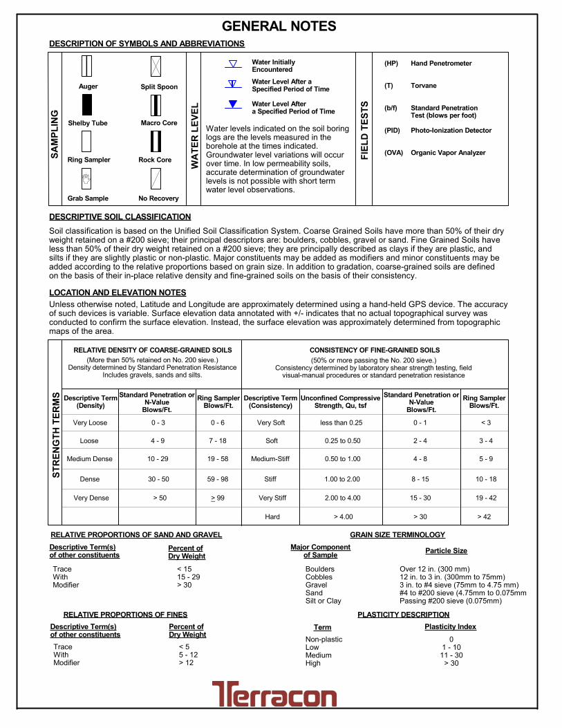
PLASTICITY DESCRIPTION
Term
< 1515 - 29> 30
Descriptive Term(s)of other constituents
Water InitiallyEncountered
Water Level After aSpecified Period of Time
Major Componentof Sample
Percent ofDry Weight
(More than 50% retained on No. 200 sieve.)Density determined by Standard Penetration Resistance
Includes gravels, sands and silts.
Hard
Unconfined CompressiveStrength, Qu, tsf
Very Loose 0 - 3 0 - 6 Very Soft less than 0.25
7 - 18 Soft 0.25 to 0.50
10 - 29 19 - 58 0.50 to 1.00
59 - 98 Stiff 1.00 to 2.00
> 99 2.00 to 4.00
LOCATION AND ELEVATION NOTES
SA
MP
LIN
G
FIE
LD
TE
ST
S
(HP)
(T)
(b/f)
(PID)
(OVA)
DESCRIPTION OF SYMBOLS AND ABBREVIATIONS
Descriptive Term(Density)
Non-plasticLowMediumHigh
BouldersCobblesGravelSandSilt or Clay
10 - 18
> 50 15 - 30 19 - 42
> 30 > 42
_
Hand Penetrometer
Torvane
Standard PenetrationTest (blows per foot)
Photo-Ionization Detector
Organic Vapor Analyzer
Water levels indicated on the soil boringlogs are the levels measured in theborehole at the times indicated.Groundwater level variations will occurover time. In low permeability soils,accurate determination of groundwaterlevels is not possible with short termwater level observations.
CONSISTENCY OF FINE-GRAINED SOILS
(50% or more passing the No. 200 sieve.)Consistency determined by laboratory shear strength testing, field
visual-manual procedures or standard penetration resistance
DESCRIPTIVE SOIL CLASSIFICATION
Unless otherwise noted, Latitude and Longitude are approximately determined using a hand-held GPS device. The accuracyof such devices is variable. Surface elevation data annotated with +/- indicates that no actual topographical survey wasconducted to confirm the surface elevation. Instead, the surface elevation was approximately determined from topographicmaps of the area.
Soil classification is based on the Unified Soil Classification System. Coarse Grained Soils have more than 50% of their dryweight retained on a #200 sieve; their principal descriptors are: boulders, cobbles, gravel or sand. Fine Grained Soils haveless than 50% of their dry weight retained on a #200 sieve; they are principally described as clays if they are plastic, andsilts if they are slightly plastic or non-plastic. Major constituents may be added as modifiers and minor constituents may beadded according to the relative proportions based on grain size. In addition to gradation, coarse-grained soils are definedon the basis of their in-place relative density and fine-grained soils on the basis of their consistency.
Plasticity Index
01 - 1011 - 30
> 30
RELATIVE PROPORTIONS OF FINES
Descriptive Term(s)of other constituents
Percent ofDry Weight
< 55 - 12> 12
TraceWithModifier
Water Level Aftera Specified Period of Time
GRAIN SIZE TERMINOLOGYRELATIVE PROPORTIONS OF SAND AND GRAVEL
TraceWithModifier
Standard Penetration orN-Value
Blows/Ft.
Descriptive Term(Consistency)
Loose
Very Stiff
Standard Penetration orN-Value
Blows/Ft.
Ring SamplerBlows/Ft.
Ring SamplerBlows/Ft.
Medium Dense
Dense
Very Dense
0 - 1 < 3
4 - 9 2 - 4 3 - 4
Medium-Stiff
8 - 15
5 - 9
30 - 50
WA
TE
R L
EV
EL
Auger
Shelby Tube
Ring Sampler
Grab Sample
Split Spoon
Macro Core
Rock Core
No Recovery
RELATIVE DENSITY OF COARSE-GRAINED SOILS
Particle Size
Over 12 in. (300 mm)12 in. to 3 in. (300mm to 75mm)3 in. to #4 sieve (75mm to 4.75 mm)#4 to #200 sieve (4.75mm to 0.075mmPassing #200 sieve (0.075mm)
ST
RE
NG
TH
TE
RM
S
> 4.00
4 - 8
GENERAL NOTES
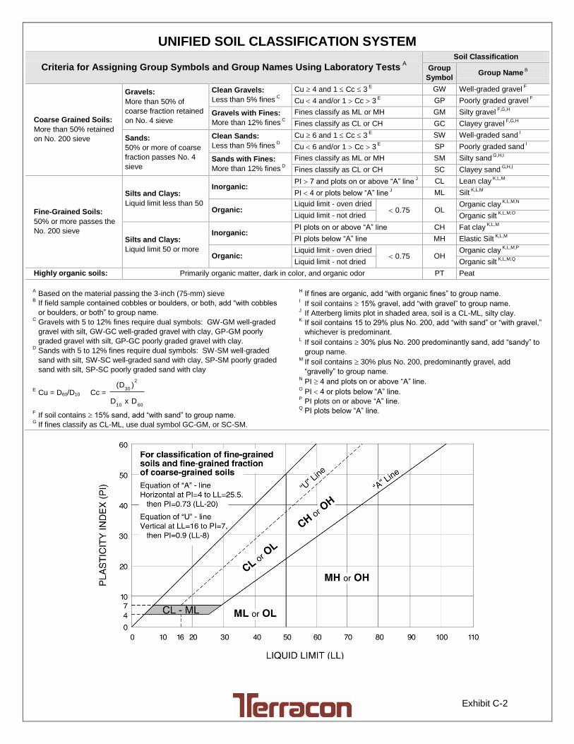
Exhibit C-2
UNIFIED SOIL CLASSIFICATION SYSTEM
Criteria for Assigning Group Symbols and Group Names Using Laboratory Tests A
Soil Classification
Group
Symbol Group Name
B
Coarse Grained Soils:
More than 50% retained
on No. 200 sieve
Gravels:
More than 50% of
coarse fraction retained
on No. 4 sieve
Clean Gravels:
Less than 5% fines C
Cu 4 and 1 Cc 3 E
GW Well-graded gravel F
Cu 4 and/or 1 Cc 3 E
GP Poorly graded gravel F
Gravels with Fines:
More than 12% fines C
Fines classify as ML or MH GM Silty gravel F,G,H
Fines classify as CL or CH GC Clayey gravel F,G,H
Sands:
50% or more of coarse
fraction passes No. 4
sieve
Clean Sands:
Less than 5% fines D
Cu 6 and 1 Cc 3 E
SW Well-graded sand I
Cu 6 and/or 1 Cc 3 E
SP Poorly graded sand I
Sands with Fines:
More than 12% fines D
Fines classify as ML or MH SM Silty sand G,H,I
Fines classify as CL or CH SC Clayey sand G,H,I
Fine-Grained Soils:
50% or more passes the
No. 200 sieve
Silts and Clays:
Liquid limit less than 50
Inorganic: PI 7 and plots on or above “A” line
J CL Lean clay
K,L,M
PI 4 or plots below “A” line J ML Silt
K,L,M
Organic: Liquid limit - oven dried
0.75 OL Organic clay
K,L,M,N
Liquid limit - not dried Organic silt K,L,M,O
Silts and Clays:
Liquid limit 50 or more
Inorganic: PI plots on or above “A” line CH Fat clay
K,L,M
PI plots below “A” line MH Elastic Silt K,L,M
Organic: Liquid limit - oven dried
0.75 OH Organic clay
K,L,M,P
Liquid limit - not dried Organic silt K,L,M,Q
Highly organic soils: Primarily organic matter, dark in color, and organic odor PT Peat
A Based on the material passing the 3-inch (75-mm) sieve
B If field sample contained cobbles or boulders, or both, add “with cobbles
or boulders, or both” to group name. C
Gravels with 5 to 12% fines require dual symbols: GW-GM well-graded
gravel with silt, GW-GC well-graded gravel with clay, GP-GM poorly
graded gravel with silt, GP-GC poorly graded gravel with clay. D
Sands with 5 to 12% fines require dual symbols: SW-SM well-graded
sand with silt, SW-SC well-graded sand with clay, SP-SM poorly graded
sand with silt, SP-SC poorly graded sand with clay
E Cu = D60/D10 Cc =
6010
2
30
DxD
)(D
F If soil contains 15% sand, add “with sand” to group name.
G If fines classify as CL-ML, use dual symbol GC-GM, or SC-SM.
H If fines are organic, add “with organic fines” to group name.
I If soil contains 15% gravel, add “with gravel” to group name.
J If Atterberg limits plot in shaded area, soil is a CL-ML, silty clay.
K If soil contains 15 to 29% plus No. 200, add “with sand” or “with gravel,”
whichever is predominant. L
If soil contains 30% plus No. 200 predominantly sand, add “sandy” to
group name. M
If soil contains 30% plus No. 200, predominantly gravel, add
“gravelly” to group name. N
PI 4 and plots on or above “A” line. O
PI 4 or plots below “A” line. P
PI plots on or above “A” line. Q
PI plots below “A” line.