geotechnical engineering review of cavity ...geotechnical engineering review of cavity expansion...
TRANSCRIPT

Geotechnical Engineering
REVIEW OF CAVITY EXPANSION MODELS
IN SOIL AND ITS APPLICATIONS
By
Nitin S. Pandit
Ronald C. Chaney
Hsai-Yang Fang
Fritz Engineering Laboratory
Department of Civil Engineering
Lehigh University
Bethlehem, Pennsylvania
Harch 1, 1983
Fritz Engineering Laboratory Report No. 462.10
REVIEW OF CAVITY EXPANSION MODELS
IN SOIL AND ITS APPLICATIONS
By
Nitin S. Pandit1
2 Ronald C. Chaney Hsai-Yang Fang 3
ABSTRACT
Various forms of analytical methods and models have
been proposed in the literature to explain the behavior of
a cavity in soil as it undergoes expansion into the surrounding
medium. The models are very complex and not suitable for quick,
routine applications in practice. A review of the cavity ex-
pansion models is presented in this paper. The basic assump-
tions made in each model, their various characteristics, and
applicability are summarized. I~ addition an examination of
the various cavity expansion concepts is conducted to clarify
the pros and cons of its application in interpretation of
pressuremeter tests and the prediction of the axial bearing
capacity of piles.
KEYWORD: Geotechnology, Soil, Model, Construction, Foundation,
Failure, piles, pressuremeters.
1 senior Staff Engineer; Woodward-Clyde Consultants; Solon, Ohio 44139
2 . Assoc~ate Professor; Dept. of Environmental Resources 'Engineering; Humboldt State University; Arcata, Califor~ia 95521
3Professor and Director; Geotechnical Engineering Division; Lehigh University; Bethlehem, Pennsylvania 18015

INTRODUCTION
The theory of soil cavity expansion deals with the
expansion of a cavity in a material of given properties.
The models developed based on this theory find application
in problems dealing with bearing capacity of deep foundations,
interpretation of pressuremeter tests, cratering by blasting
explosives and breakout resistance of ground anchors. Essen-
tially, in all the problems, observations of failure patterns
led to the belief that a certain portion of the soil mass,
associated with failure under load, could be defined as that
which is responsible for the failure. The failure patterns also
indicated that in all these cases, this causative portion - the
cavity - was wedged against and pushing into the soil mass
surrounding it. The model of cavity expansion tries to simu-
late the behavior of this cavity and to offer analytical solu
tions for its behavior under. various types of loadings.
The scope of this study will be restricted to a review of
the available models and their application in two cases: (1) pre
diction of the bearing capacity of pile foundations (deep founda
tions) and (2) the analysis of pressuremeter tests for determi-
nation of soil properties. An attempt has been made to take
into account the observation that in soil mechanics, whether a
theory is used routinely in practice to solve geotechnical prob
lems is often dependent on the simplicity of application of the
theory.
The use of cavity expansion models for the interpretation
of cone penetration tests is not in the scope of this study.
1

THEORETICAL CONSIDERATION OF CAVITY EXPANSION MODELS OF SOILS
Theory, Concept and Assumptians
The theory of cavity expansion has been developed step
by-step to model insitu soil behavior utilizing various material
properties and loading conditions. Essentially in any of these
developments, three independent constraints have to be defined
to solve the cavity expansion problem.
1) The shape of the cavity which simulates the
field conditions:
Two cavity ·shapes have been addressed so far
in the literature. These shapes are spherical
and cylindrical.
2) Properties of the soil material surrounding the
cavity:
Many types of soils have been utilized to evaluate
the ability of the individual models to predict soil
behavior. In the majority of the models, the soil
is assumed to be a homogeneous linear elastic-plastic
material. This is a reasonable assumption for materials
not exhibiting strain softening behavior such as loose
sand and soft clay. Recent theoretical work has been
directed toward the utilization of curved failure en~
velopes. This development would allow the more meaning-
ful prediction of soil behavior for stiff clays and
2

dense sands which exhibit strain-softening behavior.
In addition to considering variations in stress-strain
behavior some soil models also consider volume change,
sensitivity, dilatancy, compressibility, time de
pendency, and annulus disturbance.
3) Loading Conditions:
A review of the literature indicates that very little
attention has thus far been paid to the effects of
varying lo~ding conditions on the solutions offered
by the different models.
It is important to note that some of the models were de-
veloped to solve specific problems. Therefore, they are very
special cases of the overall problem. A summary of the various
models indicating the many assumptions involved is presented in
Table 1. A review of Table 1 indicates that all the models are
derived for very ideal materials.
Models in Use - A Review:
Out of these models, the model proposed by Vesic (1972) is
most commonly used in deep foundations such as piles by Vesic
(1975) and in stone columns by Datye and Nagraju (1977). The
models by Ladanyi (1961), Wroth & Windle (1975), and Baguelin,
et al. (1978) are commonly utilized in the interpretation of
pressuremeter tests.
3

Besides the assumptions, the following points should
be noted regarding these commonly used models.
1) Ladanyi's Models: Ladanyi (1963) showed that
compression and dilatancy characteristics play
an important role in the expansion of a cavity in
granular soils. He gave a trial and error method
for estimating the shear strength of granular soils
in drained conditions. The implicit failure criterion
in this theory is that failure occurs at a constant
stress ratio or constant effective angle of internal
friction (~) and is npt dependent on the stress level
or increasing strain levels. For a c'-¢' soil (effective
cohesion, c'), and especially for a cohesive soil, the
volumetric strains have to be ass~ssed to enable de
termination of c'-¢'. The computations are rather in
volved and therefore, the procedure is not favored in
routine practice. Ladanyi (1963) also analyzed the
problem of cavity expansion in a saturated clay in un-
drained conditions. The effects of overconsolidation
on the method were also qualitatively examined. A
modified form of this method was used later to develop
a new method for sensitive clays, Ladanyi (1972).
2) Vesic's Model: Vesic (1972) presented one of the most
simple and usable of all the cavity.expansion models,
which also takes into account volume changes in the
4
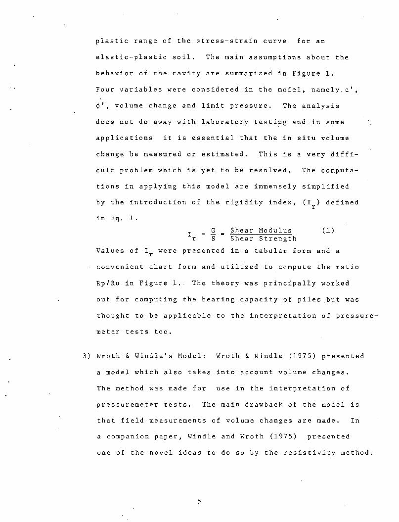
plastic range of the stress-strain curve for an
elastic-plastic soil. The main assumptions about the
behavior of the cavity are summarized in Figure 1.
Four variables were considered in the model, namely. c',
¢', volume change and limit pressure. The analysis
does not do away with laboratory testing and in some
applications it is essential that the in situ volume
change be measured or estimated. This is a very diffi-
cult problem which is yet to be resolved. The computa-
tions in applying this model are immensely simplified
by the introduction of the rigidity index,
in Eq. 1.
I r
G s
Shear Modulus Shear Strength
(I ) defined r
(1)
Values of Ir were presented in a tabular form and a
convenient chart form and utilized to compute the ratio
Rp/Ru in Figure 1. The theory was principally worked
out for computing the bearing capacity of piles but was
thought to be applicable to the interpretation of pressure-
meter tests too.
3) Wroth & Windle's Model: Wroth & Windle (1975) presented
a model which also takes into account volume changes.
The method was made for use in the interpretation of
pressuremeter tests. The main drawback of the model is
that field measurements of volume changes are made. In
a companion paper, Windle and Wroth (1975) presented
one of the novel ideas to do so by the resistivity method.
5

4) The French Model: Baguelin, et al. (1978) presented
a number of advanced theoretical techniques to account
for the effects of sensitivity, dilatancy, compress-
ibility, and annulus disturbance characteristics. This
analysis is typically restricted to sands and the data
generated primarily from pressuremeter- tests in France.
A special sectio~ has al~e-be~n dev6ted to _cohesive soils
in undrained conditions. The effects of sensitivity
and annulus disturbance in pressuremeter tests have also
been discussed.
A review of the above models indicates that all require the
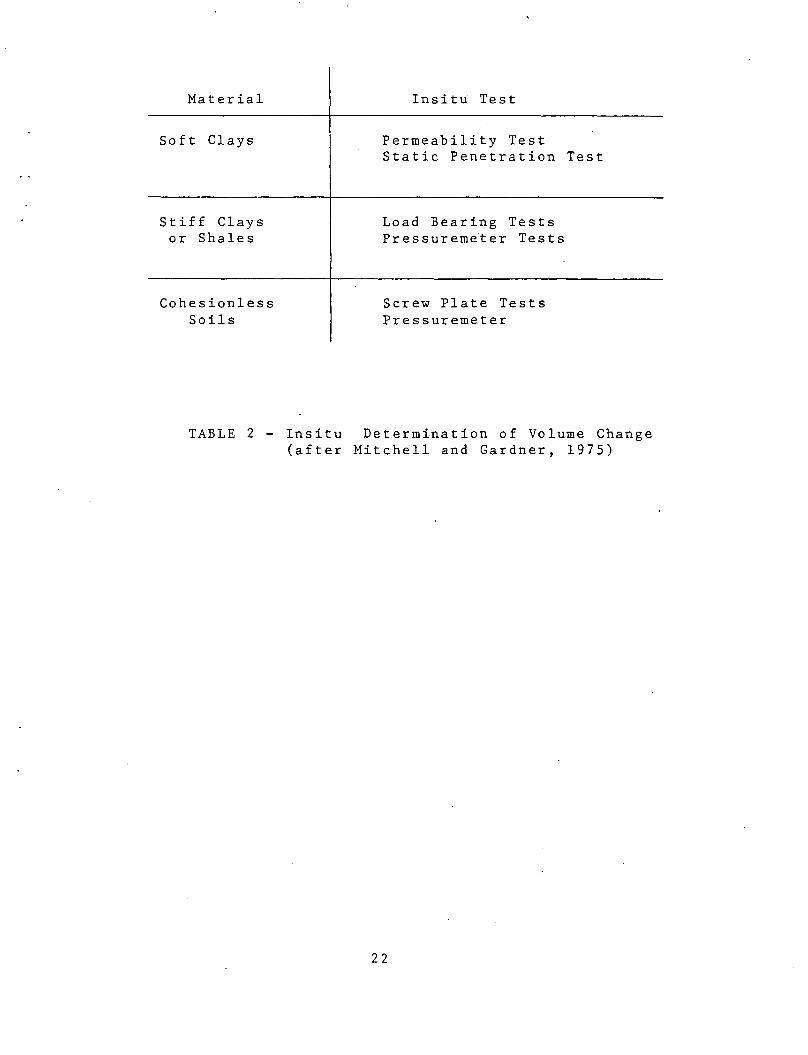
measurement of volume change under insitu conditions. A summary
of the various insitu methods for determining volume chqnge has
been presented by Mitchell and Gardner (1975). The selection
of the appropriate method was shown to be dependent on the soil
type.
In soft clays, permeability tests and static penetration
tests are believed to be most appropriate. In routine practice,
permeability tests are expensive and rare in soft clays which
implies that one is usually left with the static penetration
test. In stiff clays or shales, load bearing tests or pressure
meter tests are felt to be tbe most useful.
In determining the volume change of cohesionless soils,the
screwplate and pressuremeter tests have been found ~o be best
for all density conditions. In addition the static penetration
6
and load bearing tests may be used respectively in loose
and dense cohesionless soils. A summary of the various
methods for insitu determination of volume change is presented
in Table 2.
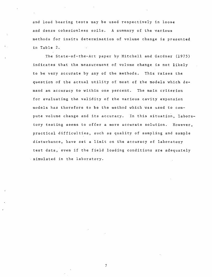
The State-of-the-Art paper by Mitchell and Gardner (1975)
indicates that the measurement of volume change is not likely
to be very accurate by any of the methods. This raises the
question of the actual utility of most of the models which de-
mand an accuracy to within one percent. The main criterion
for evaluating the validity of the various cavity expansion
models has therefore to be the method which was used to com-
pute volume change and its accuracy. In this situation, labora-
tory testing seems to offer a more accurate solution. However,
practical difficulties, such as quality of sampling and sample
disturbance, have set a limit on the accuracy of laboratory
test data, even if the field loading conditions are adequately
simulated in the laboratory.
7
APPLICATIONS
Pressuremeter
The purpose of pressuremeter tests is the evaluation
of in situ soil properties. The test has been gaining in-
creasing acceptance in the geotechnical field because (1)
it is conceptually attractive, and (2) the ease with which
it can be used in the field to simulate various loading con-
ditions. The pressuremeter like other insitu methods has
its drawbacks and limitations. A discussion of the test
has been presented by Fang (1969), Schmertmann (1975) and
more recently by Winter (1982).
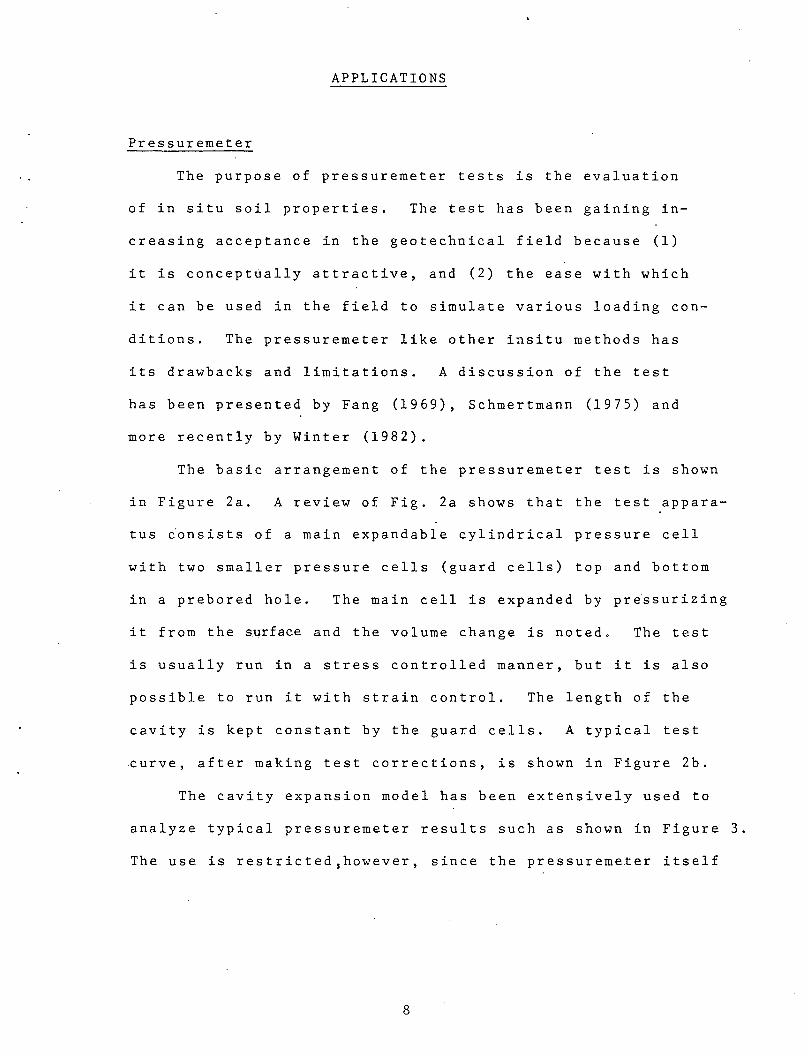
The basic arrangement of the pressuremeter test is shown
in Figure 2a. A review of Fig. 2a shows that the test appara-
tus ~onsists of a main expandable cylindrical pressure cell
with two smaller pressure cells (guard cells) top and bottom
in a prebored hole. The main cell is expanded by pre~surizing
it from the surface and the volume change is noted. The test
is usually run in a stress controlled manner, but it is also
possible to run it with strain control. The length of the
cavity is kept constant by the guard cells. A typical test
curve, after making test corrections, is shown in Figure 2b.
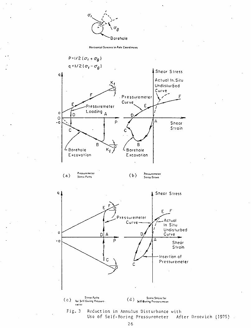
The cavity expansion model has been extensively used to
analyze typical pressuremeter results such as shown in Figure 3.
The use is restricted,however, since the pressuremeter itself
8

only measures total stresses. Attempts to measure pore
pressures have so far been relatively unsuccessful. In
addition, other factors affect the test itself and therefore
the int~rpretation of test results by cavity expansion concepts.
In cohesive soils, the concepts of cavity expansion have
tieen ~pplied to the undrained condition only or in the condition
when the loading rate effects are negligible. However, the
fact that the pressuremeter is normally installed in a prebored
hole amplifies the effects of annulus ·disturbance, which severdy
limits the test. The disturbed annulus of soil around the
pressuremeter is likely to give a value of·cohesion larger than
the value obtained from conventional tests.
The cavity expansion theory has also been applied in
pressuremeter test analysis in granular soils and c'-¢' soils.
The variation of the values of the friction angle, ¢' shows
a wide scatter in comparison with values obtained from conven-
tional tests. The main causes for the discrepancies are the
effects of dilatancy, compressibility and sensitivity. The
table below summarizes typical variations in the estimation of
granular soil properties by analyzing pressuremeter results
using cavity expansion concepts.
¢p ¢ Value obtained from pressuremeter tests (computed using cavity expansion model)
¢c ¢ Value obtained from conventional laboratory tests
9

Property Effect on ¢ Typical Variation(Degrees)
Compressibility ¢p greater than ¢c 6 7
Sensitivity ¢p greater than ¢c 6 - 7
Dilatancy ¢c greater than ¢p 12 - 15
It is evident that the results from pressuremeter tests,
as analyzed by cavity expansion conceptsJare not very reliable
if the above-mentioned factors are an important characteristic
of the soil in question.
Not all the problems arise from the model of cavity ex-
pansion, but are directly incorporated in the data due to the
practical limitations of the pressuremeter test. For instance,
the loading duration of each stress level has to be limited to the
facilitate the test. Thus the utility of the test in saturated,
undrained condition in impermeaBle soils may be open to doubt.
The effect of test procedures on the test results is shown by
Roy, et al. (1975) and Laier (1973). Another problem with the
test is to get it to follow a given stress path for vertical
loading. To solve this problem, two choices become available.
First, one could include the effects of all these variables
of the test into the theory. The second option may be to im-
prove the test and testing procedures by testing under controlled
conditions. The first choice is not attractive since the test
can only be corrected if it is refined to indicate the effects
of these variables. In addition, it is now being widely accepted
that it is neither simple nor cost-effective to obtain parameters
10

required for refining correction factors in complex models.
A recent development was made in the direction of the second
preferable option by the advent of the self-boring pressure
meter, which reduces annulus disturbance effects of the bore
hole. This is shown in Figure 3 which shows the stress paths
followed in the conventional and the new test. It is seen that
the portion of the curve due to the effect of the borehole dis
turbance in a conventional test can be substantially reduced
in the test. The reader is refetred to Drnevich (1975) for
details. The sel!-boring pressuremeter has some practical
limitations which have restricted its applicability. There
fore, to date (1982) its use is not cost-effective for routine
applications in most instances.
The only lesson to be learned from the notes above is
that there are still many "bugs" in the pressuremeter test
itself which have nothing to do with the modeling by cavity
expansion concepts. Even if the model is corrected for some
of the imperfections, the better option would be to run con
trolled tests to improve the test itself before attempting to
modify the model further. As in some other developments in
fubd~ling soil behavior, the analytical sophistication of the
cavity expansion model seems to have gone ahead of the much
needed practical refinements in the pressuremeter test techni
ques/equipment.
11
Piles
The application of cavity expansion concepts to pile
foundations is mainly attributable to Vesic, (1912), (1975),
(1977). He compared the failure patterns of end bearing
piles in model tests and in the field with the failure patterns
developed by cavity expansion to find that the end bearing
capacity could be reasonably predicted by cav~ty expansion con-
cepts.
Conventional theories predicting point resistance of piles
are based on Eq. 2.
where:
Q = c·Nc + q N·q 0
point resistance
( 2 )
cohesion, (1+2Ko)
q = mean normal stress = Qv
Ko coefficient of e~rth pressure at rest, Qv = overburden pressure
3
Nc & Nq - bearing capacity factors; NC = (Nq-l)cot ¢
The modified method, using cavity expansion, accepts the
failure pattern at the pile tip such as the one shown in Figure
4. This pattern was accepted on the basis of photographs and
data from field and model studies of the modes of failure of
end bearing piles. It is supported by data on dense and loose
sands and soft clays. The figure indicates a highly compressed
conical wedge I of soil. This wedge forces its way through
loose sand without forming slip surfaces; whereas in dense
sands, it pushes sideways to force zone II against zone III.
12

If this mechanism is accepted, then it is easy to see
that the pile advances by compression along zones II and I
and by expansion along the boundary AB. It is then assumed
that the average normal stress along AB is equal to the
pressure needed to expand the cavity in the infinite soil
mass around it.
The cavity is then assumed to be elastic-plastic with
strength parameters c-¢, deformation modulus E, poisson's
ratio._ v, and average volume change parameter A. The theory,
presented in Vesi~ (1972) leads to the Eqs. 3 and 4.
* Nq (1 +sin ¢)(I sec ¢)sin ¢/(l +sin¢) rr
I rigidity index of the soil r
A volume change parameter
(3)
whe~e: I =reduced rigidity index of the soil; I =I /(1-I *A) rr rr r r
* * (N - 1) cot ¢ q
(4)
These are now used in the Eq. (2) as the bearing capacity
factors. The values of Nq* and Nc* can be easily computed or
stored as tables or charts. Some typical values of the rigidity
index are given in Table 3.
Vesic (1972) showed that it was necessary to carry out
laboratory tests to determine ¢ (or ¢' in the case of effective
stress analysis) and that plane strain triaxial tests were re-
presentative for this problem. He also indicated that without
these tests, in situ volume change readings are essential to
use the theory.
13

One limitation of this arises from equipment limitations,
cost and the relative unavailability of the plane strain tri-
axial device for routine applications. But the major objection
to the use of Vesic's model (1972) in pile design stems from
the fact that it requires an accurate measurement of the volume
change. The fact.has been taken into account and the model
used in conditions where the accuracy of the volume change pre
diction was sufficient to enable the use of the model. For
instance, the model has been applied in other types of deep
foundations such as stone columns, by Datye & Nagaraju (1977),
where a similar failure pattern was envisaged.
14
SUMMARY AND CONCLUSIONS
The theory of cavity expansion has been developed into a
series of models by various investigators to analyze the
behavior. of a cavity in soils. All the models developed
thus far assume that the surrounding material is a homogeneous
linear elastic - plastic medium of specified properties and
an assumed failure criteria. A summary of the various cavity
expansion models is presented in Table 1.
Accuracy in the measurement of volume change is the criti
cal factor in the use of the accepted cavity expansion models.
This parameter may be used to evaluate the validity of appli
cation of the model in a particular situation.
Cavity expansion models have been used to explain and
predict pressuremeter test results. It is felt however, that
the refinements of the model are not required at this stage
since the test procedure and apparatus itself needs refinements.
Vesic's model (1972) has been commonly used for computing
the bearing capacity of piles. The model is simple to use.
The critical factor in the model is again the accurate· measure
ment of volume change with one percent error tolerance.
It should be noted that all models assume the soil to be
elastic-plastic. Thus, volumetric strains during shear (dilatancy),
and the decrease in shear strength with strain (strain softening)
are essentially ignored. Unless the basic assumption about the
rheologic properties of soils is changed, corrections will have
to be applied to account for these effects.
15
REFERENCES
Baguelin, F; Jezequel, J.-F; Lemee, E., Le Mehaute, A. (1972)
"Expansion of Cylinderical Probes in Cohesive Soils", JSMFE, ASCE, Vol. 98; SMll,
Proc. Paper 9377, p. 1129-1142.
Baguelin, F; Jezequel, J.-F; Shields, D. H; (1978)
"The Pressuremeter and Foundation Engineering"; Trans Tech. Publications,
Clausthal Germany, p. Appendix.
Baligh, M. M; (1976) "Cavity Expansion in Sands with Curved Envelopes",
JSMFE, ASCE; Proc. Paper 12536, p. 1131-1146.
Bishop, R. F; Hill, R; Mott, N.-F; (1945)
"The The~ry of Indentation and Hardness Tests", Proc. of the Physical Society,
London, No. 57, p. 147-159.
Datye, K. R; Nagraju, S. S. (1977)
"Reinforced Granular Columns - A New Design Approach", IX ICSMFE, Tokyo; Spec.
Session No. 10.
Drnevich, V. P. (197 5); "In Situ Measurement of Inti tal Stresses and Deformation
Characteristics", Proc. Conf. on In Situ Measurement of Soil Properties; Raleigh,
N.C; Vol. II p. 244-253.
Fang, H. Y. (1969); "Discussion of Pressuremeter Correlation Study", Highway Research
·Record, No. 284, p. 61-62
Gibson, R. E; Anderson, W. F; (1961)
"In Situ Measurement of Soil Properties with the Pressuremeter", Civil Engineering,
London; Vol. 56, May, p. 615-620.
16
Hill, R; (1950) "The Mathematical Theory of Plasticity";
Oxford University Press; New York.
Ladanyi, B. (1961); "Etude Theorique et Experimentale de !'expansion
daus un Sol Pulverulent d'une cavite Presintant une Synietrie Spherique ou
Cylindrique"; Annales de Travaux Publics de Belgique; Buxelles No. 2 et 4.
(1963a); "Evaluation of Pressure meter Test in Granular Soils", Proc. 2nd Pan-Am
Conf. on Soil Mech. & Found. Engg; Brazil; Vol. 1, p. 3-20.
(1963b); "Expansion of a Cavity in a Saturated Clay Medium", JSMFE, ASCE: Vol.
90, SM4, Proc. Paper 3577, p. 127-161.
(1972); "In Situ Determination of Undrained Stress Strain Behavior of Sensitive Clays
with the Pressuremeter", Canadian Geotechnical Journal, Vol. 9; No. 3.
Laier, J. E. (197 3); "Effects of Pressure meter Probe Length/Diameter
Ratio and Bore Hole Disturbance on Pressuremeter Test Results in Dry Sand"; Ph.D.
. Thesis; University of Florida.
Menard, L. (1957); "Measure In Situ des Propertes Physiques des Sols",
Annales des Ponts et Chausseis, Paris, No. 14, Mai-Juin, p. 357-377.
(1957); "An Apparatus for Measuring the Strength of Soils in Place", Ph. D. Thesis,
University of Illinois.
Mitchell, J. K; Gardner, W. S.; (197 5);
"In Situ Measurement of Volume Change Characteristics", SOA paper to Session IV,
Proc. ASCE Conf. on In Situ Measurement of Soil Properties, Raleigh, N.C.; Vol. II,
p. 279-346.
Palmer, A. C; (1972}; "Undrained Plane-Strain Expansion of a Cylindrical Cavity
in Clay - A Simple Interpretation of the Pressuremeter Test", Geotechnique; Vol.
22, No. 3, p. 451-457.
17
Roy, M.; Guneau, R.; La Rochelle, P.; Tavenas, F. (1975) "In Situ Measurement of the Properties of Sensitive Clays by Pressuremer Test", Proc. ASCE Conf. on In Situ Measurement of Soil Properties, Vol. 1, p. 350-372.
Salecon, J. (1966); "Expansion Quasi-Static d'une Cavite a Symmetrie Spherique on Cylindrique dans un milieu elasto-plasti-que", Annales des Ponts & Chaussies, Paris, Vol. III, p. 175-187.
Schmertmann, J. H. (1975); "t1easurement of In Situ Shear Strength", State-of-the Art Paper to Session III in Proc. ASCE Conf. on In Situ.Measurement of Soil Properties, Vol. II, p. 57-139.
Vesic, A. S. (1972); Expansion of Cavities in an Infinite Soil Mass", JSMFE, ASCE, Vol. 98, SM3, Proc. Paper 8790, p. 265-290.
----- (1_975); "Principles of Pile Foundation. Design", Soil Mechanics S~ries No. 38, Duke University, N. C. 46p plus 34 figures.
----- (1977); "Design of Pile Foundation", NCHRP Program Publication .. No. 42, Transportation Research Board, National Research Council, 68p.
W in d 1 e , D . ; W r o t h , C • P . (1 9 7 5 ) ; " E 1 e c t r i c a 1 R e s i s t i vi t y Me t h o d f o r Determining Volume Changes that Occur During a Pressuremeter Test", Proc. ASCE Conf. on In Situ Measurement of Soil Properties, Vol. 1, p. 497-510.
Winter, E. (1982); "Suggested Practice for Pressuremeter Testing in Soils'', Geotechnical Testing Journal, ASTM, Vol. 5, No. 3/4, Sept/Dec., p. 85-88.
W r o t h , C . P . ; W in d 1 e , D . ( 1 9 7 5 ) ; "An a 1 y s is o f P r e s s u r em e t e r T e s t .Allowing for _Volume Change", Geotechnique; Vol. 25, No. 3, Technical Notes, p. 598-604.
NOTE:
ASCE - American Society of Civil Engineers
ASTM - American Society for Testing and Materials
ICSMFE - International Conference on Soil Mechanics and Foundation Engineering.
JSMFE - .Journal of Soil Mechanics and Foundation Engineering
18

TABLE I: MODELS, ASSUMPTIONS & LIMITATIONS
r-l :>., Ill (/) (/) "-'
'"d u Q) Q) •,..j Q) ·,..j •,..j •,..j :>
THEORY p. OJ)-1-J "-' 'M 0 H 0 H Q) Q) H "-' r-l 0 r-l Q) s OJ)Q) 'M Q) ~ 0 p. ::l d p. (/)
:> Q) 0 r-l Cll 0 d Q) ..c H o..c H Q)
Q ~p.. :>up.. U)
BISHOP, HILL & MOTT M - -(1945)
HILL (1950) M I u -H H U)
..:t: .....:1 p..
I
MENARD (1957) u s H - -H U)
..:t: rj
GIBSON & ANDERSON (1951) ~ s w - -z
LADANYI (1961)
~I
s Netals Soils
CYL SPH
H .....:1
s I ?
Cylindrical Cavities Only Spherical Cavities Only
I :>., 'M u (/)
d (/)
Ill Q) :>., "-' H "-' C1j p. ·,..j
r-l Sri •,..j 0 •,..j Q u..o
- -
- ?
- -
- -
? ?
:>., u d Q)
'"d c
Q) Q)
s p. •,..j Q)
HQ
-
-
-
-
-
;,
D
~
..._. 0 Q) 0 I 'M u c "-' d Q!W Ill Ill H '"d r-l
(/),0 B ~ a ·rl Ill
::l H :>., r-l •rl rl ::l C1j ::l ~. "-' I 0 H ::l "-' :>r-l 'M Q) H (/) Q) Q) c (/) H •,..j .- ;:.. p. Q) d "-' p. C •,..j ::l Cll g Cll :>... :>·o Cll :>., ..:t:O u~ UH ou ;:<:;H
- - Both - ¢=0
rl
- - Both - Cll H Q)
d Q)
c.:>
- - CYL * C-¢
C=O - - SPH - or
¢=0
r-l Cll
- - Both H - Q)
d Q)
c.:>
Considered in Theory = Effect is Explained
Relevant Data is Used
(/)
"-' d Q)
§ 0 u
For Pressure Meters
For Piles

N 0
THEORY
LADANYI ( 19 63
LADANYI (1963
SALE CON (1966)
:'
VESIC (1972)
LADANYI (1972)
N s
Metals Soils
a)
b)
CYL SPH
TABLE I: MODELS, ASSUMPTIONS & LIMITATIONS
(Continued)
H ;>., C1l UJ UJ .u
"0 u QJ QJ "H QJ "H "H "H :> 0.. M.U .u "H 0
'""' 0
'""' QJ QJ
'""' .u
H 0 H QJ s MQJ "H QJ r.x. 0 0.. ::l j:! 0.. en :> QJ 0 H C1l 0 j:! QJ .c
'""' o.c
'""' QJ
Q P:::P... ::>up... U)
s I -
I s u -H E--< U) ~ '· t-1 p...
I
s u I ? H E-< U) ~ t-1 w
~ s I -w z H t-1
s I D
Cylindrical Cavities Only Spherical Cavities Only
I ;>., "H u (/)
c. en C1l QJ ;>., .u '""' .u C1l 0.. "H H EiH "H 0 ·H Q u.o
I I
- -
? ?
- I
- -
~ 0 QJ 0 I "H
;>., u j:! .u u j:! QJW C1l r:: C1l
'""' "0 H
QJ !1),.0 ::l QJ "H C1l "0 ::l
'""' .u '""' ~ ;>., H "H j:! H ::l C1l ::l ~ .u I 0
'""' QJ QJ ::l .u :> H ( "H QJ
'""' en QJ QJ
s 0.. j:! (/) '-' "H r: :> 0.. QJ j:! .u 0.. "H QJ j:! "H :l C1l g C1l ;>., 68 C1l :>.. E--<Q ~Q u r.x. ~ UE--< ;:;;E--<
'""' C1l
Both H
- - - - ::l j:! C1l
'""' c.!l
"0
Both QJ
- - - D .u en C1l :>..
'""' C1l
::lH .u .u C1l
U)
? ? - Both - ?
H - - - Both - C1l
'""' QJ j:! QJ
c.!l
"0 QJ
* .u
- - - CYL C1l
'""' ::l ;>., .u C1l. c:;:: cUH~ U)U
V Considered in Theory * ~ Effect is Explained D Relevant Data is Used
en .u j:! QJ
~ 0 u
Drained Condition
Only
Undrained Condition
Only
Pile Design
Pressure-Meter: !undrained, IPiane-Strain Cqnditions I

N 1--'
THEORY
PALHER (1972)
BAGUELIN, ET.AL. (1972)
WROTH & WINDLE (1975)
BAGUELIN, ET.AL. (1978)
BALIGH
M
s
(1980)
Hetals Soils
CYL SPH
TABLE I: HODELS, ASSUHPTIONS & L U!ITATIONS
'U Q)
0. 0 H
.--! 0 QJ ~ > QJ
Q
s
s
s
s
s
.--! C\1 Ul () QJ
·ri •ri OOJJ 0 H
.--! QJ 0 0. QJ 0
..r:: H P:::P...
~ w z H ....:1
:>.. Ul JJ QJ ·ri •ri > JJ ·ri
QJ QJ H JJ s OOQJ ·ri :l c 0. Ul
.--! C\1 0 c o..r:: H QJ ;>up... U'l
Cylindrical Cavities Only Spherical Cavities Only
(Continued)
I :>... ·ri () Ul c Ul Cll Q) :>... JJ H JJ C\1 0. ·ri
.--! Sr--I ·ri 0 ·ri Q u.o
"-1 QJ 0 I
:>... () c () c QJ~ r:: C\1 H QJ Ul.O :l QJ 'U :l H JJ H 0 :>-. c .--! :l Cll :l ~ JJ
QJ QJ :l JJ > .--! c •ri QJ El 0. c Ul H ·ri r- > p..
•ri QJ c ·ri :l Cll ~ C\1 :>-. E-tQ ~Q u ~ ~ UE-t
CYL
CYL
CYL
CYL
SPH
,... 0
•ri JJ Cll
'U ·ri .--!
I 0 H Ul QJ c 6'8
?
.--! Cll
•ri H QJ QJ JJ 0. Cll :>-.
::E:E-t
'U QJO JJ II C\l-6-H ::l :>-.
-1-) Cll Cllr--1 U'lU
¢=0
(J)
'U r:: Cll
U'l
V Considered in Theory * - Effect is Explained D = Relevant Data is Used
Ul JJ c QJ
§ 0 u
PressureMeter; Un drained, Plane-Strc in Condition
As Above
Drained Condition Only. Undrained Condition Touched Upotn
PressureMeter
Modificatioh of
Vesic (1972D Concepts
Material
Soft Clays
Stiff Clays or Shales
Cohesionless Soils
Insitti Test
Permeability Test Static Penetration Test
Load Bearing Tests Pressuremeter Tests
Screw Plate Tests Pressuremeter
TABLE 2 - Insitu Determination of Volume Change (after Mitchell and Gardner, 1975)
22

TABLE ·3
TYPICAL VALUES OF RIGIDITY INDEX, /,
(a) sands and silts
Relative Hean Normal Rigidity Soil censity stress level index Sourc;e
Dr 00 (kg/cm2) I r
0.1 200 Vesic 80\ 1 118 and
~hattahoochee sand 10 52 Clough 100 12 (1958)
20\ <l.l 140 1 85
Otta\.la sand 62\ 0.05 265 Roy (1956) 21\ o.os 89
Piedmont silts 0.70 10-30 Vesic (1972)
(b) clays (undrained conditions)
Plasticity Water oc Effective .Rigidity Soil index content ratio stress level index Source
Ip ,o <J (kg/cm2)
Weald clay 25 23.1\ 1 2.1 99 22.5\ 24 0.35 10
Ladanyi Dra:nmen clay 19 24.9\ 1.5 267 (1963)
25.1\ 1 2.5 259 27.H 4. 0 23 3
Lagunillas 50 65'!.* l 6.5 390 clay 4. 0 300
*prior to consolidation
2 3 -

Figure 1: Vesic's model of an expanding spherical cavity
Assumed initial conditions:
(1) A soil mass is under an isotropic effective stress.
(2) The soil mass is homogeneous.
(3) There exists a spherical cavity of radius Ri (dashed line).
(4) Soil behavior in the elastic range can be described by a modulus of deformation, E,
and a poisson's ratio, V. In the plastic range, it can be described by the Mohr
Coulomb shear strength parameters, C-tl, and the average volumetric strain (which
can be defined from the knowledge of the state of stress and volume change-stress
relationships in the plastic range).
Assumed loading and behavior:
(1) The internal pressure of the cavity is uniformly increased causing the cavity to
expand.
(2) This causes an annulus of soil around the cavity to go into the plastic range.
(3) At a particular internal pressure Pu, the qwity has a radius, Ru and the liinit of the
annulus in the plastic range is defined by Rp. Beyond this, the soil mass is still in
the elastic range.
24

CONTIO:c!>l. UNIT ~--------~
II =II =1/:::/1=11 :IJ: II= II
(a)
3oREHOLE
(b)
TVPICAL CU!ZVE
VOLUI-1£. CHANGE
Fig. 2 The Pressuremeter
25
..
Q
Horiront•l Strrnrs in Potc Coordin"rs
P:I/2{CTr+CTe)
q:l/2(o-,-o-8)
. Pressuremeter Curve
Shear Stress
Actual ln.Situ Undisturbed
F
c o~-:---+=------.,----
-a
Q
0
-o
p
c Shear S!rain
Lole E;.;cavation E :r.cavotion
(a)
(c)
Prrssurr mr ter Strru Pothl
E F a
(b) Prtnurcmctf'r Suru-Str•in
Snear Stress
J Pre ssuremeter Curve-
F
/ 1_Actuol
I In Situ
D A
S!rru PJ:tlu
'"' xlf-!lnrinr Prcuun· lnC'!rr
p
c
(d)
1 Undisturbed Curve
Shear Strain
/--+--Insertion of Pressuremeter
Suru StrJin !ot StU-Burin& Prr\\UtC'(I"'('Icr
Fig. 3 R~duction in Annulus Disturbance Usc of Self-Boring Pressurcmeter
with After Drnevich (1975)
26

..
CON IC.AL. WEDC4-e
Fig. 4 Vesic 1 s Model of Pile Behavior
27
Sctt. IN PLASTIC
RA"l~E