geotechnical investigation...
TRANSCRIPT

DOVER, NH I WORCESTER, MA I WESTFIELD, MA I PORTLAND, ME I WEST HARTFORD, VT I ROCKY HILL, CT
GEOTECHNICAL INVESTIGATION REPORT Revision 1 – May 3, 2017
CONGRESS AND CHESTNUT STREET STREETSCAPE AND
UTILITIES PROJECT
PORTSMOUTH, NEW HAMPSHIRE
Prepared For:
City of Portsmouth
1 Junkins Avenue
Portsmouth, New Hampshire 03801
Prepared By:
John Turner Consulting, Inc.
19 Dover Street
Dover, New Hampshire 03820
JTC Project No.: 17-15-011
May 3, 2017
GEOTECHNICAL ▼ ENVIRONMENTAL ▼ RESIDENT ENGINEERING ▼ TESTING

TABLE OF CONTENTS
Report Text, Limitations,
& Tables
Existing Conditions Plan, Site Plan, Archway Foundation Plan,
& Exploration Location Plan
Test Boring Logs, Key to Symbols and Descriptions,
& Ledge Probe Summary
Geotechnical Laboratory Testing Reports
Site Photographs

Rep
ort T
ex
t, Lim
itatio
ns, a
nd
Tab
les

Congress and Chestnut Street Streetscape and Utilities Project– Portsmouth, NH
Geotechnical Investigation Report – May 3, 2017
Page 1 of 12
GEOTECHNICAL INVESTIGATION REPORT
Prepared by:
JOHN TURNER CONSULTING, INC.
19 Dover Street
Dover, New Hampshire 03820
www.ConsultJTC.com
TO: Ryan A. Flynn, E.I.T.
Construction Project Coordinator
Department of Public Works
City of Portsmouth
680 Peverly Hill Road
Portsmouth, NH 03801
Office: (603) 766-1413
Cell: (603) 828-6325
FROM: Rachel Cannon Judson Zachar, P.E.
Staff Geotechnical Engineer Senior Geotechnical Engineer
DATE: May 2, 2017
RE: GEOTECHNICAL INVESTIGATION REPORT – Rev. 1 (May 3, 2017)
CONGRESS AND CHESTNUT STREET STREETSCAPE
AND UTILITIES PROJECT
PORTSMOUTH, NEW HAMPSHIRE
JTC Project No. 17-15-011
John Turner Consulting, Inc. (JTC) is pleased to present this Geotechnical Investigation Report
for a proposed Congress and Chestnut Street Streetscape and Utilities Project to be located in
Portsmouth, New Hampshire. JTC conducted geotechnical explorations, laboratory testing, and
engineering evaluations in general accordance with our proposed scope of services submitted to
City od Portsmouth on February 6, 2017. Our work was authorized on February 15, 2017.
The purpose of the geotechnical investigation was to obtain information on the subsurface
conditions at the site and to provide geotechnical engineering recommendations to support the
planning, design, and construction of the proposed development. Geotechnical explorations and
laboratory testing services were performed in March of 2017.
This report summarizes available project information, presents the geotechnical exploration and
laboratory testing programs, describes the subsurface conditions encountered, and provides
geotechnical engineering recommendations to support the planning, design, and construction of
the proposed Congress and Chestnut Street Streetscape and Utilities Project. The contents of this
report are subject to the attached Limitations.

Congress and Chestnut Street Streetscape and Utilities Project– Portsmouth, NH
Geotechnical Investigation Report – May 3, 2017
Page 2 of 12
1.0 PROJECT INFORMATION
The following subsections provide general descriptions of the site, the regional geologic setting,
and the proposed development.
1.1 Site Description
The site of the proposed Congress and Chestnut Street Streetscape and Utilities Project is located
on Congress, Chestnut, and Porter Streets in Portsmouth, New Hampshire. The roads are subject
to moderate to heavy flow of standard passenger vehicles and delivery trucks, and provide direct
access to numerous businesses and residences. An Existing Conditions Plan (attached) provided
by Altus Engineering, Inc. and dated January 20, 2017 indicates moderately sloping ground surface
contours with existing grades ranging from about +20 feet to +32 feet within the footprint of the
proposed development.
1.2 Regional Geologic Setting
JTC’s review of the “Surficial Geologic Map of the Portsmouth and Kittery Quadrangles,
Rockingham County, New Hampshire” (Larson, G.J.; 1992) indicates that the native soils are
likely to vary among Glacial and Postglacial Water-Laid Deposits, Marine Offshore Deposits, and
Glacial Till. Glacial and Postglacial Water-Laid Deposits include sand, gravel, and silt deposited
by meltwater streams discharging into the late glacial sea and/or wave-derived nearshore deposits
during marine offlap. Marine Offshore Deposits typically include marine sand, silt, and/or clay
associated with the Presumscot Formation. Glacial Till is generally a heterogeneous mixture of
sand, silt, clay, and stones deposited directly by glacial ice. Stratification is rare and it usually
overlays bedrock. The referenced map also indicates some areas (typically near West Road) that
may include relatively thin (less than 10 feet thick) layers of overburden soils and/or shallow
bedrock.
1.3 Proposed Development
JTC understands that the proposed development involves the construction of a new ornamental
arch to span across the end of Chestnut Street where it terminates at Congress Street. JTC further
understands that the underground utilities along the three streets are to be replaced/improved.
We understand that design details are still being developed, but the structural engineer, JSN
Associates, Inc., provided preliminary site-specific structural loading as follows:
• The intent will be to support the arch on an isolated shallow spread footing, each
approximately 6’ to 7’ square; and
• Foundation loads will be on the order of 20 kips or less (less than 10 kips per footing).
2.0 GEOTECHNICAL EXPLORATIONS & LABORATORY TESTING
The primary components of the geotechnical exploration and laboratory testing programs are

Congress and Chestnut Street Streetscape and Utilities Project– Portsmouth, NH
Geotechnical Investigation Report – May 3, 2017
Page 3 of 12
described in the following subsections.
2.1 Geotechnical Explorations
Soil Exploration Corp (SoilEx) to perform two (2) geotechnical test borings (designated as B-1
and B-2) and four (4) ledge probes (designated LP-1 through LP-4, inclusive) via a truck-mounted
Mobile B57 drill rig. JTC directed the drilling, testing, and sampling activities and logged the
subsurface conditions encountered at each exploration location.
The proposed exploration locations were selected by the design team. JTC field-located the
proposed explorations considering existing site features and proposed development, and under the
constraints of drill rig access and utility conflicts. Subsequently, the relative location of each
exploration was established via measurements from existing site features and scaling the
dimensions onto the provided plan(s). The attached Exploration Location Plan depicts the
approximate exploration locations.
The test borings were advanced to depths ranging from 11 to 17.25 feet below the ground surface
(bgs) utilizing 2¼-inch inside-diameter continuous-flight hollow-stem-augers (HSAs). As the
borings were advanced, standard penetration tests (SPTs) were conducted at regular intervals and
soil samples were obtained via 2-inch outside-diameter split-spoon samplers driven by a 140-
pound hammer. SPTs were performed in general accordance with ASTM D1586, Standard Test
Method for Penetration Test and Split-Barrel Sampling of Soils. Soil samples were sealed in
moisture-tight containers and returned to JTC’s office for further review, classification, and/or
geotechnical laboratory testing. The ledge probes were advanced to depths ranging from 2 to 5.5
feet bgs. The test borings (and probes) were backfilled with soil cuttings upon completion of
drilling.
Detailed records of the drilling, testing, and sampling performed and the soil, bedrock, and
groundwater conditions observed at each test boring location are provided on the attached Test
Boring Logs. General descriptions of the subsurface conditions observed at each ledge probe
location are provided in the attached Ledge Probe Summary.
2.2 Geotechnical Laboratory Testing
JTC selected representative soil samples for geotechnical laboratory testing at our in-house
laboratory. The following tests were performed:
• 6 Moisture contents;
• 5 Particle-size analyses; and
• 1 Atterberg Limits.
Geotechnical laboratory testing was performed in general accordance with ASTM procedures. Test
results are provided on the attached Geotechnical Laboratory Testing Reports.

Congress and Chestnut Street Streetscape and Utilities Project– Portsmouth, NH
Geotechnical Investigation Report – May 3, 2017
Page 4 of 12
3.0 SUBSURFACE CONDITIONS
The following subsections describe the site soil, bedrock, and groundwater conditions
encountered, based on results of the geotechnical explorations and laboratory testing. Detailed
descriptions of the conditions observed at each test boring are provided on the attached Test Boring
Logs. General descriptions of the conditions observed at each auger probe location are provided
in the attached Ledge Probe Summary.
3.1 Soils
The overburden soils encountered at the test boring locations appear to be generally consistent
with those described by the published geologic data. The primary soil strata are briefly described
in the paragraphs below.
3.1.1 Road Base
Road Base materials were encountered directly beneath 3-5 inches of asphalt at each exploration
location. The Road Base typically consisted of brown to dark brown silty sand (SM) with few
gravel. The Road Base was about 0.5 to 1 feet thick at most exploration locations. The Road Base
was typically medium dense and moist.
3.1.2 Existing Fill
Existing Fill materials were encountered directly beneath the Road Base at each test boring
location and at most auger probe locations. The Existing Fill was usually described as brown silty
sand with gravel (SM) or as brown silty sand (SM). Where encountered (or inferred), the Existing
Fill was approximately 1 to 4 feet thick and extended to depths of about 2.5 to 5.5 feet bgs. The
Existing Fill was typically described as loose to medium dense to dense based on SPT N-values.
3.1.3 Marine Offshore Deposits
Native soils described as olive brown sandy lean clay (CL) and/or olive brown fine to medium
sand (SM) were encountered directly beneath the Fill at each test boring location. This deposit is
interpreted to be a Marine Offshore Deposit of Marine Clay and Marine Sand. Where fully
penetrated, the clay and/or sand extended to depths ranging from 8.5 to 13.5 feet bgs and was about
3.5 to 8.5 feet thick.
The Marine Clay (CL) typically extended to depths ranging from 8.5 to 13.5 feet bgs. The clay
was described as medium stiff to very stiff, based on visual-manual observations and SPT N-values
that ranged from 8 to 20 and averaged about 12. The moisture content of the clay ranged from
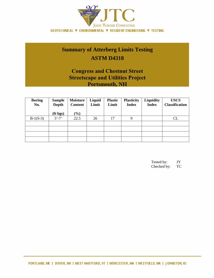
about 22.5% to 22.8%, based on two (2) tests. One Atterberg limits determination yielded liquid
limit (LL), plastic limit (PL), and plasticity index (PI) values of 26, 17, and 9, respectively. The
moisture content was typically above the PL, which is evidenced by a liquidity index (LI) value of
0.6. The available data indicate that the Marine Clay is moderately to heavily overconsolidated.

Congress and Chestnut Street Streetscape and Utilities Project– Portsmouth, NH
Geotechnical Investigation Report – May 3, 2017
Page 5 of 12
The Marine Sand (SM) was encountered in boring B-2 at 5 feet bgs and extended to a depth of 6
feet bgs. Marine sand was not encountered in boring B-1. The sand was medium dense based on
SPT N-values.
3.1.4 Glacial Till
Olive brown silty sand with gravel (SM) was encountered beneath the Marine Offshore Deposits
at each boring location at depths ranging from about 8.5 to 13.5 feet bgs. This stratum is
interpreted to be Glacial Till. The Glacial Till was fully penetrated (i.e., practical refusal to further
penetration of the augers) in both borings, and varied from about 2.5 to 4 feet in thickness and
extended to depths ranging from 11 to 17.25 feet bgs.
The Glacial Till was typically described as medium dense to very dense based on N-values that
ranged from 25 to 50. One (1) particle-size analysis performed on a representative sample
indicated 39% sand, 32% gravel, and 29% silt/clay. The moisture content was 8.1%, based on one
(1) test.
3.2 Bedrock
Practical refusal to further penetration of the augers and/or split-spoon sampler was encountered
at each test boring and ledge probe location at depths ranging from about 2 to 17.25 feet bgs, and
was encountered at depths ranging from 11 to 17.25 feet in the vicinity of the proposed archway.
The refusal in each exploration is interpreted to be refusal on the probable top of bedrock. Bedrock
is not expected to impact the construction of the arch, based on the results of this investigation.
Bedrock may impact the redevelopment of underground utilities. As such, a limited amount of
rock removal should be expected and a variety of removal methods should be anticipated and
budgeted for (obtain unit costs), including mechanical excavation, ripping, hoe-ram, and blasting.
3.3 Groundwater
Groundwater and/or wet soils were encountered in boring B-2 at a depth of approximately 2 feet
bgs, at the time of drilling. Boring B-2 is located in close proximity to a street drain and wet soils
are likely due to snow meltwater runoff from sidewalks and street.
Short-term (i.e., during drilling, upon completion of drilling, and/or a few hours after drilling)
water levels observed in test borings should be considered approximate. Site groundwater levels
should be expected to fluctuate seasonally and in response to precipitation events, construction
activity, site use, and adjacent site use.
4.0 GEOTECHNICAL DESIGN & CONSTRUCTION RECOMMENDATIONS
The evaluation of the site and the proposed development was based on the subsurface conditions
encountered at the geotechnical test borings, results of geotechnical laboratory testing, provided
site/grading plans, and assumed/preliminary structural loading conditions, as described herein.

Congress and Chestnut Street Streetscape and Utilities Project– Portsmouth, NH
Geotechnical Investigation Report – May 3, 2017
Page 6 of 12
JTC believes that the site soils are generally suitable for support of the proposed arch, provided
the site/subgrade is prepared as described herein.
The existing Asphalt, Road Base, and Existing Fill materials are not suitable for direct support of
the arch foundations. These soils should be completely removed from the footing zone (i.e., the
proposed footing plus at least 5 feet laterally) during the initial phases of site preparation and grading.
Subsequently, the proposed arch can be supported upon shallow foundations bearing on
undisturbed native Marine Sand/Clay, Glacial Till and/or on Structural Fill or crushed stone built-
up from properly prepared native soil subgrades, provided that the design and construction
recommendations presented herein are satisfied.
4.1 Site Preparation and Grading
Site preparation and grading should be performed in accordance with the following procedures:
• A geotechnical engineer should directly observe site preparation and grading activities;
• The site soils contain substantial proportions of fine sand, silt, and clay, and may degrade
and/or become unworkable when subjected to construction traffic or other disturbance
during wet conditions. As such, site preparations, grading, and earthworks should be
performed during a dry season if possible. The Contractor shall be aware of these
conditions and must take precautions to minimize subgrade disturbance. Such precautions
may include diverting storm run-off away from construction areas, reducing traffic in
sensitive areas, minimizing the extent of exposed subgrade if inclement weather is forecast,
backfilling excavations and footings as soon as practicable, grading (and compacting)
exposed subgrades to promote surface water run-off, and maintaining an effective
dewatering program, as necessary. Over-excavation to remove degraded or unworkable
subgrade soils should be anticipated and budgeted (cost and schedule);
• Any existing buildings, structures, and/or associated foundations (including footings,
foundation walls, slabs-on-grade, and/or basements) should be completely removed from
the proposed arch footprints and replaced/backfilled with properly placed and compacted
Structural Fill;
• Any existing subsurface utilities and underground structures should be completely
removed from the footprint of the proposed arch and replaced/backfilled with properly
placed and compacted Structural Fill. Any existing subsurface utilities in proposed
pavement areas should be removed and/or appropriately abandoned in place (e.g., pressure
grouting), as approved by the on-site geotechnical engineer;
• The site should be cleared and stripped of any existing asphalt-concrete pavement not
designated to remain; existing trees/vegetation not designated to remain; Topsoil, rootmat,
forest mat; loamy/organic-laden Subsoil; and any otherwise unsuitable materials;
o The explorations indicate that most of the site is presently covered with 3 to 5 inches
of Asphalt.
• Existing Fill, Road Base, and any otherwise unsuitable materials should be completely
removed from the proposed arch footprint (i.e., the proposed arch footprint plus at least 5

Congress and Chestnut Street Streetscape and Utilities Project– Portsmouth, NH
Geotechnical Investigation Report – May 3, 2017
Page 7 of 12
feet laterally);
o The geotechnical explorations indicate that Existing Fill materials extend to depths
on the order of 5 to 5.5 feet bgs proximate to the proposed arch; and
o Additional Undocumented Fill materials should also be expected proximate to
existing building(s) and subsurface utilities.
• In cut areas, the final foot of excavation should be performed using a smooth-edged cutting
bucket (no teeth) to minimize subgrade disturbance;
• Following clearing, stripping, and/or cutting, the exposed subgrade soils should be proof-
rolled/proof-compacted using a large walk-behind compactor. However, proof-
rolling/proof-compacting should not be performed if/when the exposed subgrade soils are
wet (i.e., due to presence of groundwater, stormwater, perched water, etc.) because this
may result in soil pumping and instability. Therefore, the proof-rolling/proof-compacting
efforts, including the number of passes and whether to employ static or vibratory methods,
should be directed by the on-site geotechnical engineer;
o Any loose, soft, wet, and/or otherwise unsuitable soils (typically evidenced by
rutting, pumping, and/or deflection of the subgrade) should be over-excavated to
expose suitable soils, or other remedial measures should be taken, as approved by
the on-site geotechnical engineer; and
o The over-excavation should then be backfilled with properly placed and compacted
Structural Fill.
• Structural Fill should be used for subgrade fill within footing pads. The placement of
Structural Fill materials to achieve design subgrades in footing pads should not begin until
the exposed subgrade soils have been directly observed and approved by the on-site
geotechnical engineer;
• Common Fill is acceptable for subgrade fill in parking and driveway areas. The placement
of Common Fill materials to achieve design subgrades in pavement areas should not begin
until the exposed subgrade soils have been directly observed and approved by the on-site
geotechnical engineer; and
• Structural Fill and Common Fill materials and placement and compaction requirements are
provided in the attached Table 1.
4.2 Shallow Foundations
Based on the subsurface conditions encountered at the exploration locations and our current
understanding and assumptions relative to the proposed development, the following preliminary
foundation design recommendations are provided:
• The existing Asphalt, Existing Fill, and Road Base materials are not suitable for direct
support of shallow foundations. These materials should be completely removed from the
footprint(s) of the arch, plus 5 feet laterally, as described in Section 4.2.1;
• The arch can be supported on a system of continuous and/or isolated shallow spread
footings bearing on undisturbed native Marine Clay/Sand, Glacial Till, and/or on Structural

Congress and Chestnut Street Streetscape and Utilities Project– Portsmouth, NH
Geotechnical Investigation Report – May 3, 2017
Page 8 of 12
Fill or crushed stone built-up from properly prepared native soil subgrades;
• Shallow foundations may be designed using an allowable bearing pressure of 3,000 psf.;
• Isolated column footings should have a minimum width of 3 feet;
• Exterior footings should be founded at least 4 feet below the lowest adjacent grade to
provide adequate frost protection;
• Total post-construction settlements due to applied foundation loads are estimated to be 0.25
to 0.5 inches or less, based on column footing widths of up to 7 feet. Differential
settlements between isolated column footings are estimated to be less than 0.25 inches.
The estimated settlements and resulting angular distortion are anticipated to be within the
allowable limits for this type of structure;
• The design of the arch foundation should consider pull-out (uplift), sliding, and overturning
due to wind-induced uplift, lateral, and/or rotational loads.
o Resistance to net tensile loads (i.e., uplift) can be provided by the weight of the
foundation elements, the weight of the soil directly above the foundation elements
(if applicable), and the superstructure. The structural designer should evaluate the
actual design tensile loads and the actual tensile resistance (i.e., uplift resistance)
based upon the actual foundation configuration, targeting a 1.5 factor of safety;
o Resistance to lateral loads can be provided by friction along the base of the
foundations. An interface friction angle, φ, of about 24 degrees is recommended for
mass concrete against silty fine to medium sand and/or stiff clay, which results in a
frictional factor, tan φ, of 0.44. Only dead loads should be used in the calculation
of available interface friction;
o An active earth pressure coefficient, Ka, of 0.33 and a passive earth pressure
coefficient, Kp, of 1.5 (3.0 divided by reduction factor of 2) may be considered for
resistance to lateral loads and overturning; and
o To resist overturning, the net reaction should be located within the middle third of
the footing base.
Recommendations for shallow foundation subgrade preparation/construction and foundation
backfilling are provided as follows:
• A geotechnical engineer or his/her representative should directly observe foundation
subgrade preparation activities;
• If shallow and/or perched groundwater is encountered, it must be removed in advance of
excavation and continuously maintained at least 2 feet below the bottom of excavation and
subsequent construction grade until the backfilling is complete;
• Excavations for shallow foundations must extend into undisturbed native Marine
Clay/Sand, Glacial Till and/or Structural Fill built-up from properly prepared native soils,
as described herein;
• The native foundation subgrade soils will be sensitive to moisture and will readily disturb

Congress and Chestnut Street Streetscape and Utilities Project– Portsmouth, NH
Geotechnical Investigation Report – May 3, 2017
Page 9 of 12
or soften if exposed to wet conditions and construction activities. Therefore, the final foot,
at a minimum, of excavation for foundations should be performed using a smooth-edged
cutting bucket (no teeth) to minimize subgrade disturbance. If seepage/shallow
groundwater and/or precipitation result in wet conditions, the exposed foundation subgrade
should be protected with a 6-inch (minimum) thick layer of ¾-inch minus crushed stone
encased in a geotextile fabric (e.g., Mirafi 140N or equal). The crushed stone shall be
placed immediately upon exposure of the native foundation subgrade soils and densified
with a plate compactor until exhibiting stable conditions. The purpose of the crushed stone
is to protect the fine-grained subgrade soils from disturbance, facilitate construction
dewatering (if necessary), and provide a dry/stable subgrade upon which to progress
construction;
o If Undocumented Fill and/or otherwise unsuitable soils/materials are encountered
at the foundation subgrade, over-excavations should remove all Fill and/or
unsuitable soils within the footing zone of influence, which is defined as the area
extending laterally 1 foot from edges of the footing and then outward and
downward at a 1H:1.5V (horizontal to vertical) splay of bearing until a suitable
native subgrade soil is encountered; and
o Any over-excavations should be backfilled with properly placed and compacted
Structural Fill or crushed stone as approved by the on-site geotechnical engineer.
• Prior to setting forms and placing reinforcing steel, a geotechnical engineer should directly
observe footing subgrades;
o Footing subgrades should be level or suitably benched and free of standing water
and/or debris;
o Loose, soft, wet, frozen, or otherwise unsuitable soils should either be re-compacted
or over-excavated to a suitable subgrade, as approved by the on-site geotechnical
engineer; and
o Over-excavations should be backfilled with properly placed and compacted
Structural Fill or crushed stone as approved by the on-site geotechnical engineer.
• Foundation subgrade soils should be protected against physical disturbance, precipitation,
and/or frost throughout construction. Surface water run-on/run-off should be diverted away
from open foundation excavations. The Contractor shall ultimately be responsible for the
means and methods to protect the foundation subgrade during construction;
• Exterior footings and piers should be backfilled with non-frost-susceptible fill in order to
mitigate potential adverse effects of frost. Backfill for exterior footings and piers should
consist of well-graded, free-draining, granular soil conforming to the requirements of
Clean Granular Fill, as described in the attached Table 1. Alternatively, a suitable bond
break (such as rigid polystyrene insulation) may be provided as approved by the on-site
geotechnical engineer. In this case, footings may be backfilled with Common Fill (see
attached Table 1) having a maximum particle-size of 3 inches, as approved by the on-site
geotechnical engineer;
• Backfill for footings and piers should be placed in uniform horizontal lifts having a
maximum loose lift thickness of 8 inches and compacted to 95 percent of its modified proctor
Congress and Chestnut Street Streetscape and Utilities Project– Portsmouth, NH
Geotechnical Investigation Report – May 3, 2017
Page 10 of 12
maximum dry density (MPMDD; per ASTM D1557). Thinner lifts may be required in order
to achieve the required compaction criteria; and
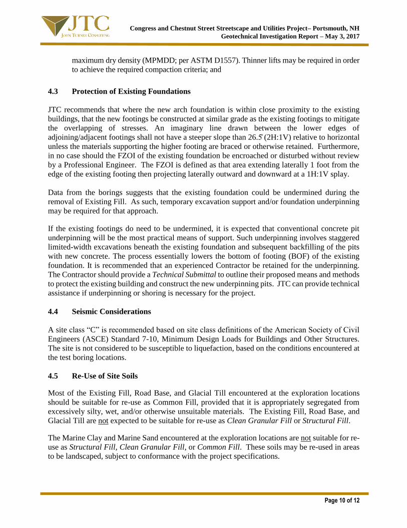
4.3 Protection of Existing Foundations
JTC recommends that where the new arch foundation is within close proximity to the existing
buildings, that the new footings be constructed at similar grade as the existing footings to mitigate
the overlapping of stresses. An imaginary line drawn between the lower edges of
adjoining/adjacent footings shall not have a steeper slope than 26.5̊ (2H:1V) relative to horizontal
unless the materials supporting the higher footing are braced or otherwise retained. Furthermore,
in no case should the FZOI of the existing foundation be encroached or disturbed without review
by a Professional Engineer. The FZOI is defined as that area extending laterally 1 foot from the
edge of the existing footing then projecting laterally outward and downward at a 1H:1V splay.
Data from the borings suggests that the existing foundation could be undermined during the
removal of Existing Fill. As such, temporary excavation support and/or foundation underpinning
may be required for that approach.
If the existing footings do need to be undermined, it is expected that conventional concrete pit
underpinning will be the most practical means of support. Such underpinning involves staggered
limited-width excavations beneath the existing foundation and subsequent backfilling of the pits
with new concrete. The process essentially lowers the bottom of footing (BOF) of the existing
foundation. It is recommended that an experienced Contractor be retained for the underpinning.
The Contractor should provide a Technical Submittal to outline their proposed means and methods
to protect the existing building and construct the new underpinning pits. JTC can provide technical
assistance if underpinning or shoring is necessary for the project.
4.4 Seismic Considerations
A site class “C” is recommended based on site class definitions of the American Society of Civil
Engineers (ASCE) Standard 7-10, Minimum Design Loads for Buildings and Other Structures.
The site is not considered to be susceptible to liquefaction, based on the conditions encountered at
the test boring locations.
4.5 Re-Use of Site Soils
Most of the Existing Fill, Road Base, and Glacial Till encountered at the exploration locations
should be suitable for re-use as Common Fill, provided that it is appropriately segregated from
excessively silty, wet, and/or otherwise unsuitable materials. The Existing Fill, Road Base, and
Glacial Till are not expected to be suitable for re-use as Clean Granular Fill or Structural Fill.
The Marine Clay and Marine Sand encountered at the exploration locations are not suitable for re-
use as Structural Fill, Clean Granular Fill, or Common Fill. These soils may be re-used in areas
to be landscaped, subject to conformance with the project specifications.

Congress and Chestnut Street Streetscape and Utilities Project– Portsmouth, NH
Geotechnical Investigation Report – May 3, 2017
Page 11 of 12
4.6 Construction Monitoring and Quality Control Testing
A qualified geotechnical engineer or representative should be retained to review the site
preparation and grading activities and foundation subgrade preparations, at a minimum. Similarly,
quality control testing, including in-place field density and moisture tests, should be performed to
confirm that the specified compaction is achieved. It is recommended that JTC be retained to
provide earthwork construction monitoring and quality control testing services.
Quality control testing recommendations are provided as follows:
• During site grading and foundation subgrade preparation, 1 field density test should be
performed for every lift (maximum 8 inches per lift) of Structural Fill placement, at a
minimum;
• During foundation and/or pier backfilling, 1 field density test should be performed for
every lift (maximum 8 inches per lift) of Clean Granular Fill placement, at a minimum;
and
• During backfilling of utility trenches, at least 1 test should be conducted on Structural Fill
for every lift (maximum 8 inches per lift) of trench.
4.7 Additional Considerations
Additional design recommendations are provided as follows:
• Exterior concrete sidewalks shall be underlain by at least 15 inches of Clean Granular Fill.
The thickness of the Clean Granular Fill shall be increased to no less than 24 inches for
exterior concrete slabs located adjacent to exterior doorways and ramps to provide
additional frost protection at building entry/exit points;
• The exterior ground surface adjacent to buildings should be sloped away from the building
to provide for positive drainage. Similarly, the final surface materials adjacent to buildings
should be relatively impermeable to reduce the volume of precipitation infiltrating into the
subsurface proximate to building foundations. Such impermeable materials include cement
concrete, bituminous concrete, and/or vegetated silty/clayey topsoil; and
• Permanent fill or cut slopes should have a maximum slope of 2.5H:1V (horizontal to
vertical) or flatter for dry conditions. Permanent fill or cut slopes should be no steeper than
3H:1V for wet/submerged conditions (e.g., stormwater basin) unless a properly designed
surface slope stabilization system (e.g. rip rap, geosynthetics) is provided.
Additional construction recommendations are provided as follows:
• Safe temporary excavation and/or fill slopes are the responsibility of the Contractor.
Excavations should be conducted in accordance with local, state, and federal (OSHA)
requirements, at a minimum. If an excavation cannot be properly sloped or benched due to
space limitations, adjacent structures, and/or seepage, the Contractor should install an

Congress and Chestnut Street Streetscape and Utilities Project– Portsmouth, NH
Geotechnical Investigation Report – May 3, 2017
Page 12 of 12
engineered shoring system to support the temporary excavation;
• Subgrade conditions will be influenced by excavation methods, precipitation, stormwater
management, groundwater control(s), and/or construction activities. Most of the site soils
are poorly-drained, moisture-sensitive, and considered susceptible to disturbance when
exposed to wet conditions and construction activities. As such, the Contractor shall be
aware of these conditions and must take precautions to minimize subgrade disturbance.
Such precautions may include diverting storm run-off away from construction areas,
reducing traffic in sensitive areas, minimizing the extent of exposed subgrade if inclement
weather is forecast, backfilling excavations and footings as soon as practicable, and
maintaining an effective dewatering program, as necessary;
• Proper groundwater control and stormwater management are necessary to maintain site
stability. Groundwater should be continuously maintained at least 2 feet below the working
construction grade until earthworks and/or backfilling are complete;
• If groundwater seepage and/or wet soils due to shallow groundwater are observed, a ¾-
inch minus crushed stone base should be placed atop the exposed subgrade soils. The stone
should be immediately placed atop the undisturbed subgrade and then tamped with a plate
compactor until exhibiting stable conditions. The stone shall be protected, as required, with
a geotextile filter fabric such as Mirafi 140N or equal. The purpose of the stone base is to
protect the wet subgrade, facilitate dewatering, and provide a dry/stable base upon which
to progress construction; and
• All slopes should be protected from erosion during (and after) construction.
5.0 CLOSING
We trust the contents of this report are responsive to your needs at this time. Should you have any
questions or require additional assistance, please do not hesitate to contact our office.

LIMITATIONS
Explorations
1. The analyses and recommendations presented in this report are based in part upon the data obtained
from widely-spaced subsurface explorations. Subsurface conditions between exploration locations
may vary from those encountered at the exploration locations. The nature and extent of variations
between explorations may not become evident until construction. If variations appear, it will be
necessary to re-evaluate the recommendations of this report.
2. The generalized soil profile described in the text is intended to convey trends in subsurface
conditions. The boundaries between strata are approximate and idealized and have been developed
by interpretation of widely-spaced explorations and samples; actual strata transitions are probably
more gradual. For specific information, refer to the individual test pit and/or boring logs.
3. Water level readings have been made in the test pits and/or test borings under conditions stated on
the logs. These data have been reviewed and interpretations have been made in the text of this
report. However, it must be noted that fluctuations in the level of the groundwater may occur due
to variations in rainfall, temperature, and other factors differing from the time the measurements
were made.
Review
4. It is recommended that John Turner Consulting, Inc. be given the opportunity to review final design
drawings and specifications to evaluate the appropriate implementation of the geotechnical
engineering recommendations provided herein.
5. In the event that any changes in the nature, design, or location of the proposed areas are planned,
the conclusions and recommendations contained in this report shall not be considered valid unless
the changes are reviewed and conclusions of the report modified or verified in writing by John
Turner Consulting, Inc.
Construction
6. It is recommended that John Turner Consulting, Inc. be retained to provide geotechnical
engineering services during the earthwork phases of the work. This is to observe compliance with
the design concepts, specifications, and recommendations and to allow design changes in the event
that subsurface conditions differ from those anticipated prior to the start of construction.
Use of Report
7. This report has been prepared for the exclusive use of City of Portsmouth in accordance with
generally accepted soil and foundation engineering practices. No other warranty, expressed or
implied, is made.
8. This report has been prepared for this project by John Turner Consulting, Inc. This report was
completed for preliminary design purposes and may be limited in its scope to complete an accurate
bid. Contractors wishing a copy of the report may secure it with the understanding that its scope is
limited to preliminary geotechnical design considerations.

TABLE 1
Recommended Soil Gradation & Compaction Specifications
Structural Fill
SIEVE SIZE PERCENT PASSING
BY WEIGHT
5-inch 100
¾-inch 60 - 100
No. 4 20 - 80
No. 200 0 - 10
NOTES: 1. For use as structural load support below foundations and as subgrade fill within building
pads. Structural Fill placed beneath building foundations should include the Footing Zone
of Influence which is defined as that area extending laterally one foot from the edge of the
footing then outward and downward at a 1H:1.5V splay.
2. ¾-inch crushed stone may be used in wet conditions.
3. Structural Fill should be free of construction and demolition debris, frozen soil, organic
soil, peat, stumps, brush, trash, and refuse;
4. Structural Fill should not be placed on soft, saturated, or frozen subgrade soils;
5. Structural Fill should be placed in lifts not exceeding 12 inches for heavy vibratory rollers
and 8 inches for vibratory plate compactors.
6. Place and compact within ± 3% of optimum moisture content.
7. Compact to at least 95% relative compaction per ASTM D1557.
8. The adequacy of the compaction efforts should be verified by field density testing.

Clean Granular Fill
SIEVE SIZE PERCENT PASSING
BY WEIGHT
3-inch 100
¾-inch 60 – 90
No. 4 20 – 70
No. 200 2 – 8
NOTES: 1. For minimum 9-inch base below floor slabs-on-grade.
2. For minimum 15-inch base for exterior concrete slabs exposed to frost.
3. For minimum 24-inch base at exterior ramps, aprons, and loading bays adjacent to
entrances/exit ways.
4. For use as footing and foundation wall backfill.
5. For use as backfill behind unbalanced foundation/retaining walls.
6. Place in lifts not exceeding 12 inches for heavy vibratory rollers and 8 inches for vibratory
plate compactors.
7. Place and compact within ± 3% of optimum moisture content.
8. Compact to at least 95% relative compaction per ASTM D1557.
9. Compaction efforts should be verified by field density testing.
Common Fill
SIEVE SIZE PERCENT PASSING
BY WEIGHT
6-inch 100
¾-inch 60 – 100
No. 4 20 – 85
No. 200 0 – 25
NOTES: 1. For use as common/subgrade fill for athletic fields, parking areas, and embankments.
2. For use as foundation wall backfill if used in conjunction with a bond break and
sized/screened to 3-inch minus.
3. Place in lifts not exceeding 12 inches.
4. Maximum stone size should not exceed ½ the actual lift thickness.
5. Compact to at least 92% relative compaction per ASTM D1557 when placed as subgrade
fill in parking areas or roadway embankments.
6. Compact to at least 95% relative compaction per ASTM D1557 when placed as foundation
wall backfill in conjunction with a bond break.
7. Compaction efforts should be verified by field density testing.

Exis
ting
Co
nd
ition
s P
lan
, Site
Pla
n, A
rch
wa
y F
ou
nd
atio
n P
lan
, &
Exp
lora
tion
Lo
catio
n P
lan


Notes:
1. Explorations were performed on March 22, 2017 under the direction of JTC. 2. Exploration locations should be considered approximate. 3. Refer to the Test Boring Logs and Summary of Auger Probes for the subsurface conditions encountered at each exploration location. 4. Basemap source: January 20, 2017 “Existing Conditions Plan” prepared by Altus Engineering, Inc. 5. Not to scale.
City of Portsmouth 1 Junkins Avenue
Portsmouth, New Hampshire 03801
Congress and Chestnut Street Streetscape and Utilities Project
Portsmouth, New Hampshire
EXPLORATION LOCATION PLAN
B-1
B-2
LP-4 LP-1
LP-3
LP-2
= boring
= ledge probe

Test B
orin
g L
og
s, K
ey to
Sym
bo
ls a
nd
Des
crip
tion
s, &
Led
ge P
rob
e S
um
mary

0
2.5
5
7.5
10
12.5
15
17.5
4.5" Asphalt0.375
Dark brown, silty sand (SM) - few gravel medium dense; moist: ROAD BASE
1.375Brown, silty sand (SM) - few gravel; medium dense; moist:
FILL- Becomes loose
5.5Olive brown, sandy lean clay (CL) - stiff; moist: MARINE
CLAYPen Su = 2,500 psf
Torvane Su = 400 psf
8.5
Olive brown, silty sand w/ gravel (SM) - very dense; moist: GLACIAL TILL
- Rock in tipBoring terminated at 11 ft.
Auger refusal on probable bedrock
SS01
SS02
SS03
SS04
7763
2233
43610
2550/5"
--
16.9
78.6
28.9
PROJECT NO.: 17-15-011
ELEVATION:
LOG OF BORINGNo. B-1
LOGGED BY: RC
PROJECT: Congress and Chestnut Street Streetscape and Utilities Project
CLIENT: City of Portsmouth
PROJECT LOCATION: Chestnut Street, Portsmouth NH LOCATION: See Exploration Location Plan DRILLER: SoilEx
DRILLING METHOD: HSA DATE: 3/22/17
DEPTH TO - WATER> INITIAL: AFTER 24 HOURS:
De
pth
(fe
et)
Description
Gra
ph
ic
Ele
vatio
n (
feet)
Sa
mp
leN
o.
Blo
wC
ou
nts
% <
#2
00 TEST RESULTS
10 20 30 40 50Penetration -
Water Content -
Plastic Limit Liquid Limit
Figure
Th
is i
nfo
rma
tio
n p
ert
ain
s o
nly
to
th
is b
ori
ng
an
d s
ho
uld
no
t b
e i
nte
rpre
ted
as
be
ing
in
dic
ati
ve
of
the
sit
e.
PAGE 1 of 1

0
2.5
5
7.5
10
12.5
15
17.5
5" Asphalt0.4
Tan brown, silty sand (SM) - few gravel; medium dense; moist: ROAD BASE
2.4Brown, silty sand with gravel (SM) - loose; moist: FILL
- Becomes wet (located near street drain)
5Olive brown, fine to medium sand (SM) - trace silt; medium
dense; moist: MARINE SAND6
Olive brown, sandy lean clay (CL) - very stiff; moist: MARINECLAY
Pen Su = 3,000 psfTorvane Su = 400 psf
- Becomes medium stiffPen Su = 1,500 psf
Torvane Su = 400 psf
13.5
Olive brown, silty sand w/ gravel (SM) - medium dense; moist: GLACIAL TILL
Auger refusal on probable bedrockBoring terminated at 17.25 ft.
SS01
SS02
SS03
SS04
SS05
SS06
7763
5432
5878
381212
44410
7111419
PROJECT NO.: 17-15-011
ELEVATION:
LOG OF BORINGNo. B-2
LOGGED BY: RC
PROJECT: Congress and Chestnut Street Streetscape and Utilities Project
CLIENT: City of Portsmouth
PROJECT LOCATION: Chestnut Street, Portsmouth NH LOCATION: See Exploration Location Plan DRILLER: SoilEx
DRILLING METHOD: HSA DATE: 3/22/17
DEPTH TO - WATER> INITIAL: AFTER 24 HOURS:
De
pth
(fe
et)
Description
Gra
ph
ic
Ele
vatio
n (
feet)
Sa
mp
leN
o.
Blo
wC
ou
nts
% <
#2
00 TEST RESULTS
10 20 30 40 50Penetration -
Water Content -
Plastic Limit Liquid Limit
Figure
Th
is i
nfo
rma
tio
n p
ert
ain
s o
nly
to
th
is b
ori
ng
an
d s
ho
uld
no
t b
e i
nte
rpre
ted
as
be
ing
in
dic
ati
ve
of
the
sit
e.
PAGE 1 of 1

Layer:
Seam:
Parting:
> 3" thick
1/16" to 3" thick
< 1/16" thick
N-Value
Standard Split Spoon Sample
Moist:
TYPICAL SYMBOLS
Stiff
Inorganic lean clay. Low to medium plasticity.PI > 7 and plots on or above "A" line.
TERMS DESCRIBING STRUCTURE
Little:
SPT Notes: WR = Weight of Rods; WH = Weight of Hammer
15% to 25%
Few:
CLEANSANDS
SANDS WITHFINES
FINEGRAINED
SOILS
SILTS AND CLAYS
(More than 50%of coarse fractionRETAINED on
No. 4 sieve)
(Less than 5% fines)
(Less than 5% fines)
Well graded sands or sand-gravelmixtures; trace or no fines.
(Liquid Limit LESS than 50)
(Liquid Limit of 50 or GREATER)
Shelby Tube
GC
Occasional:
(i.e. particles > 3", organics, debris, etc.)
Sonic or Vibro-Core Sample
0 - 4
4 - 10
(More than 50%RETAINED onNo. 200 sieve)
10 - 30
30 - 50
Over 50
GRAVELS
SANDS
Consistency
Very Soft
Soft
Very Stiff
TERMS DESCRIBING MATERIALS
Silty gravels or gravel-sand-silt mixtures.
SAND
BOUNDARY CLASSIFICATIONS: Soils possessing characteristics of two groups are designated by combinationsof group symbols.
(More than 12% fines)
(More than 12% fines)
Medium
U.S. STANDARD SIEVE SIZE
GRAVELCobbles Boulders
12"3"
CoarseFine
3/4"
GM
SM
SC
ML
Peat and other highly organic soils. Decomposedvegetable tissue. Fibrous to amorphous texture.
Organic silts and clays. High plasticity.
Inorganic elastic silt. PI plots below "A" line.
Organic silts, clays, and silty clays. Low tomedium plasticity.
References: ASTM D 2487 (Unified Soil Classification System) and ASTM D 2488 (Visual-Manual Procedure).
GP
CL
OL
MAJOR DIVISIONS
SILTS AND CLAYS
GW
Inorganic fat clay. High plasticity.PI plots on or above "A" line.
OH
PT
Poorly graded sands or sand-gravelmixtures, trace or no fines.
Silty sands or sand-gravel-silt mixtures.
Clayey sands or sand-gravel-clay mixtures.N-Value
CLEANGRAVELS
GRAVELSWITH FINES
GRAVEL, SAND, & SILT (NON-PLASTIC)
(50% or moreof coarse fraction
PASSES theNo. 4 sieve)
CH
SP
SW
Poorly graded gravels or gravel-sandmixtures; trace or no fines.
Well graded gravels or gravel-sandmixtures; trace or no fines.
HIGHLY ORGANIC SOILS
KEY TO SYMBOLS AND
DESCRIPTIONS
Inorganic silts or rock flour. Non-plastic or veryslightly plastic. PI < 4 or plots below "A" line.
MH
Clayey gravels or gravel-sand-claymixtures.
GROUPSYMBOLS
COARSEGRAINED
SOILS
No.4No.10
CoarseSILT OR CLAY
Fine
No.200 No.40
Auger Cuttings
3" Split Spoon Sample
Dynamic Cone Penetrometer
Bulk/Grab Sample
Water Table after 24 hours
Rock Core
Vane Shear
Geoprobe Sample
Water Table at time of drilling
Hard
GENERAL DESCRIPTIONS
(50% or morePASSES the
No. 200 sieve)
> 25%
10% to 25%
Particles present, but < 10%
TERMS DESCRIBING SOILS
Relative Density
Very Loose
Loose
Medium Dense
Very Dense
Dense
CORRELATION OF STANDARD PENETRATION TEST (SPT)WITH RELATIVE DENSITY AND CONSISTENCY
Medium Stiff
25% to 50%
0 - 2
2 - 4
4 - 8
8 - 15
Su (psf)
0 - 250
250 - 500
Over 4000
500 - 1000
1000 - 2000
Visible/free water
Dry:
Over 30
15 - 30 2000 - 4000
SILT (PLASTIC) & CLAY
TERMS DESCRIBING MOISTURE
Some:
Trace: Particles present, but < 5%
(excludes particles > 3", organics, debris, etc.)
Absence of moisture; dusty
Damp, but no visible water
Wet:
5% to 15% Frequent:
Many:

Client:Project:
City of Portsmouth Congress and Chestnut Street Streetscape and Utilities Project
JTC Proj. No.: 17-15-011Drill Date(s): 03/22/17JTC Rep.: Rachel CannonDriller: SoilEx
ProbeNo.
Asphalt Thickness Road Base Thickness
Existing FillThickness
Depthto
Ledge
Depthto
Water
Notes
(inches) (inches) (ft) (ft bgs) (ft bgs)LP-1 4 approx. 6-12 1.0-2.0+ 5.5 N/A Porter
LP-2 4 approx. 6-12 - - N/A CongressEncountered former concrete sewer main at 0.75ft bgs.Offset 18" to south; same results. Abndoned location per client request.
LP-3 5 approx. 12 - 2.0 N/A ChestnutEcountered concrete at 1ft bgs. Offset to east (approx. 18 inches from curb); same results. Drill through concrete into ledge.
LP-4 3 approx. 6-12 1.0-2.0+ 4.0 N/A Porter
Notes: 1
SUMMARY OF LEDGE PROBE FINDINGS
Stratum thicknesses are based on visual observations of cuttings and drilling difficulty and should be considered approximate.
Location
(street name)

Geo
tec
hn
ical L
ab
ora
tory
Testin
g R
ep
orts

001
(no specification provided)*
PL= LL= PI=
USCS (D 2487)= AASHTO (M 145)=
D90= D85= D60=D50= D30= D15=D10= Cu= Cc=
Remarks
Silty sand
3/41/23/8#4#10#20#40#50
#100#200
100.097.992.885.980.975.760.139.521.916.9
SM
7.8719 4.0488 0.42440.3578 0.2379
In-Situ Moisture: 19.2%
3-22-17 3-24-17
Ted Moody
Travis Carpenter
VP of Geotech Engineering
3-22-17
City of Portsmouth
Congress and Chestnut Street Streetscape and Utilities Project
17-15-011
Material Description
Atterberg Limits (ASTM D 4318)
Classification
Coefficients
Date Received: Date Tested:
Tested By:
Checked By:
Title:
Date Sampled:Location: B-1(S-2)Sample Number: 17-155 Depth: 2-4'
Client:
Project:
Project No: Figure
TEST RESULTS
Opening Percent Spec.* Pass?
Size Finer (Percent) (X=Fail)
PE
RC
EN
T F
INE
R
0
10
20
30
40
50
60
70
80
90
100
GRAIN SIZE - mm.
0.0010.010.1110100
% CobblesCoarse
% Gravel
Fine Coarse Medium
% Sand
Fine Silt
% Fines
Clay
0.0 0.0 14.1 5.0 20.8 43.2 16.9
6 in
.
3 in
.
2 in
.
1½
in.
1 in
.
¾ in
.
½ in
.
3/8
in.
#4
#1
0
#2
0
#3
0
#4
0
#6
0
#1
00
#1
40
#2
00
Particle Size Distribution Report

002
(no specification provided)*
PL= LL= PI=
USCS (D 2487)= AASHTO (M 145)=
D90= D85= D60=D50= D30= D15=D10= Cu= Cc=
Remarks
Sandy Lean clay
#20#40#50
#100#200
100.099.298.194.778.6
CL
0.1159 0.0946
In-Situ Moisture: 22.5%
3-22-17 3-24-17
Jason Spry
Travis Carpenter
VP of Geotech Engineering
3-22-17
City of Portsmouth
Congress and Chestnut Street Streetscape and Utilities Project
17-15-011
Material Description
Atterberg Limits (ASTM D 4318)
Classification
Coefficients
Date Received: Date Tested:
Tested By:
Checked By:
Title:
Date Sampled:Location: B-1(S-3)Sample Number: 17-156 Depth: 5'-7'
Client:
Project:
Project No: Figure
TEST RESULTS
Opening Percent Spec.* Pass?
Size Finer (Percent) (X=Fail)
PE
RC
EN
T F
INE
R
0
10
20
30
40
50
60
70
80
90
100
GRAIN SIZE - mm.
0.0010.010.1110100
% CobblesCoarse
% Gravel
Fine Coarse Medium
% Sand
Fine Silt
% Fines
Clay
0.0 0.0 0.0 0.0 0.8 20.6 78.6
6 in
.
3 in
.
2 in
.
1½
in.
1 in
.
¾ in
.
½ in
.
3/8
in.
#4
#1
0
#2
0
#3
0
#4
0
#6
0
#1
00
#1
40
#2
00
Particle Size Distribution Report

003
(no specification provided)*
PL= LL= PI=
USCS (D 2487)= AASHTO (M 145)=
D90= D85= D60=D50= D30= D15=D10= Cu= Cc=
Remarks
Silty sand with gravel
13/41/23/8#4#10#20#40#50
#100#200
100.079.874.972.567.659.453.448.545.336.928.9
SM
22.4444 20.9218 2.14520.5162 0.0828
In-Situ Moisture: 8.1%
3-22-17 3-24-17
Jason Spry
Travis Carpenter
VP of Geotech Engineering
3-22-17
City of Portsmouth
Congress and Chestnut Street Streetscape and Utilities Project
17-15-011
Material Description
Atterberg Limits (ASTM D 4318)
Classification
Coefficients
Date Received: Date Tested:
Tested By:
Checked By:
Title:
Date Sampled:Location: B-1(S-4)Sample Number: 17-157 Depth: 10'-12'
Client:
Project:
Project No: Figure
TEST RESULTS
Opening Percent Spec.* Pass?
Size Finer (Percent) (X=Fail)
PE
RC
EN
T F
INE
R
0
10
20
30
40
50
60
70
80
90
100
GRAIN SIZE - mm.
0.0010.010.1110100
% CobblesCoarse
% Gravel
Fine Coarse Medium
% Sand
Fine Silt
% Fines
Clay
0.0 20.2 12.2 8.2 10.9 19.6 28.9
6 in
.
3 in
.
2 in
.
1½
in.
1 in
.
¾ in
.
½ in
.
3/8
in.
#4
#1
0
#2
0
#3
0
#4
0
#6
0
#1
00
#1
40
#2
00
Particle Size Distribution Report

004
(no specification provided)*
PL= LL= PI=
USCS (D 2487)= AASHTO (M 145)=
D90= D85= D60=D50= D30= D15=D10= Cu= Cc=
Remarks
Well-graded gravel with sand
13/41/23/8#4#10#20#40#50
#100#200
100.098.192.184.252.828.315.4
9.37.34.93.8
GW
11.5954 9.7470 5.56354.4307 2.1772 0.82260.4698 11.84 1.81
In-Situ Moisture: 3.3%
3-22-17 3-27-17
Jason Spry
Travis Carpenter
VP of Geotech Engineering
3-22-17
City of Portsmouth
Congress and Chestnut Street Streetscape and Utilities Project
17-15-011
Material Description
Atterberg Limits (ASTM D 4318)
Classification
Coefficients
Date Received: Date Tested:
Tested By:
Checked By:
Title:
Date Sampled:Location: LP-1 AsphaltSample Number: 17-159 Depth: 0'
Client:
Project:
Project No: Figure
TEST RESULTS
Opening Percent Spec.* Pass?
Size Finer (Percent) (X=Fail)
PE
RC
EN
T F
INE
R
0
10
20
30
40
50
60
70
80
90
100
GRAIN SIZE - mm.
0.0010.010.1110100
% CobblesCoarse
% Gravel
Fine Coarse Medium
% Sand
Fine Silt
% Fines
Clay
0.0 1.9 45.3 24.5 19.0 5.5 3.8
6 in
.
3 in
.
2 in
.
1½
in.
1 in
.
¾ in
.
½ in
.
3/8
in.
#4
#1
0
#2
0
#3
0
#4
0
#6
0
#1
00
#1
40
#2
00
Particle Size Distribution Report

005
(no specification provided)*
PL= LL= PI=
USCS (D 2487)= AASHTO (M 145)=
D90= D85= D60=D50= D30= D15=D10= Cu= Cc=
Remarks
Silty sand
3/41/23/8#4#10#20#40#50
#100#200
100.099.397.689.677.365.854.847.531.822.5
SM
4.8742 3.4271 0.57350.3361 0.1353
In-Situ Moisture: 10.0%
3-22-17 3-27-17
Ted Moody
Travis Carpenter
VP of Geotech Engineering
3-22-17
City of Portsmouth
Congress and Chestnut Street Streetscape and Utilities Project
17-15-011
Material Description
Atterberg Limits (ASTM D 4318)
Classification
Coefficients
Date Received: Date Tested:
Tested By:
Checked By:
Title:
Date Sampled:Location: LP-1 Road BaseSample Number: 17-160 Depth: 0.5'
Client:
Project:
Project No: Figure
TEST RESULTS
Opening Percent Spec.* Pass?
Size Finer (Percent) (X=Fail)
PE
RC
EN
T F
INE
R
0
10
20
30
40
50
60
70
80
90
100
GRAIN SIZE - mm.
0.0010.010.1110100
% CobblesCoarse
% Gravel
Fine Coarse Medium
% Sand
Fine Silt
% Fines
Clay
0.0 0.0 10.4 12.3 22.5 32.3 22.5
6 in
.
3 in
.
2 in
.
1½
in.
1 in
.
¾ in
.
½ in
.
3/8
in.
#4
#1
0
#2
0
#3
0
#4
0
#6
0
#1
00
#1
40
#2
00
Particle Size Distribution Report

GEOTECHNICAL ▼ ENVIRONMENTAL ▼ RESIDENT ENGINEERING ▼ TESTING
DOVER, NH I WORCESTER, MA I WESTFIELD, MA I PORTLAND, ME I WEST HARTFORD, VT I JOHNSTON, RI
Boring
No.
Sample Depth
(ft bgs)
Moisture Content
(%)
B-2(S-4) 7’-9’ 22.8
Notes:
1. This table summarizes results of “stand-alone” moisture content testing performed on
selected samples. Additional moisture content test results are provided on the associated
Particle-Size Distribution Report, Summary of Atterberg Limits Testing Report,
Summary of Organic Content Testing Report, and/or other geotechnical laboratory
testing reports, as applicable.
Tested by: JY
Checked by: TC
Summary of Moisture Content Testing
ASTM D2216
Congress and Chestnut Street Streetscape and Utilities Project
Portsmouth, NH
GEOTECHNICAL ▼ ENVIRONMENTAL ▼ RESIDENT ENGINEERING ▼ TESTING
PORTLAND, ME I DOVER, NH I WEST HARTFORD, VT I WORCESTER, MA I WESTFIELD, MA I JOHNSTON, RI
Boring No.
Sample Depth
(ft bgs)
Moisture Content
(%)
Liquid Limit
Plastic Limit
Plasticity Index
Liquidity Index
USCS Classification
B-1(S-3) 5’-7’ 22.5 26 17 9 CL
Tested by: JY Checked by: TC
Summary of Atterberg Limits Testing ASTM D4318
Congress and Chestnut Street Streetscape and Utilities Project
Portsmouth, NH

Site
Ph
oto
gra
ph
s

Page 1 of 1
SITE PHOTOGRAPHS
CONGRESS AND CHESTNUT STREET STREETSCAPE AND UTILITIES PROJECT – PORTSMOUTH, NEW HAMPSHIRE
Proposed location of arch, To Northeast
Proposed location of arch, To North
Multiple utility conflicts at Chestnut & Porter
Set up on LP-3, to North
Sample of FILL in B-2 Sample of native SAND in B-2