geotechnical investigation and pavement design … · geotechnical investigation and pavement...
TRANSCRIPT
GEOTECHNICAL INVESTIGATION AND PAVEMENT DESIGN REPORT
SCHEDULE 'C' CLASS ENVIRONMENTAL ASSESSMENT
PROPOSED WIDENING OF MISSISSAUGA ROAD
FROM FINANCIAL DRIVE TO QUEEN STREET WEST (LOCATION 1)
CITY OF BRAMPTON, ONTARIO
Submitted to:
THE REGIONAL MUNICIPALITY OF PEEL
c/o Amec Foster Wheeler Environment & Infrastructure,
a Division of Amec Foster Wheeler Americas Limited
3450 Harvester Road, Suite 100
Burlington, Ontario L7N 3W5
Canada
Submitted by:
Amec Foster Wheeler Environment & Infrastructure,
a Division of Amec Foster Wheeler Americas Limited
50 Vogell Road, Units 3 & 4
Richmond Hill, Ontario L4B 3K6
Canada
Tel: (905) 415-2632
Fax: (416) 415-1686
23 February 2018
Amec Foster Wheeler Reference: TP115085
The Regional Municipality of Peel Geotechnical Investigation and Pavement Design Report Schedule ‘C’ Class Environmental Assessment Proposed Widening of Mississauga Road from Financial Drive to Queen Street West, City of Brampton, Ontario (Location 1)
Page i
23 February 2018
Amec Foster Wheeler Reference Number: TP115085
TABLE OF CONTENTS
1.0 INTRODUCTION ............................................................................................................... 1
1.1 Project Description..................................................................................................... 2
1.2 Regional Geology ...................................................................................................... 3
2.0 INVESTIGATION PROCEDURE ....................................................................................... 4
2.1 Overall Investigation Approaches .............................................................................. 5
2.2 Geotechnical Investigation ......................................................................................... 8
2.2.1 Road Widening .............................................................................................. 8 2.2.2 Bridge Widening ............................................................................................ 9 2.2.3 Retaining Walls .............................................................................................. 9 2.2.4 Underground Utilities ..................................................................................... 9
2.3 Pavement Investigation ............................................................................................. 9
3.0 ROAD WIDENING ............................................................................................................11
3.1 Sub-surface Conditions ............................................................................................11
3.1.1 Asphaltic Concrete ........................................................................................12 3.1.2 Fill Soils ........................................................................................................12 3.1.3 Silty Sand / Sandy Silt / Sand .......................................................................12 3.1.4 Sandy Gravel / Gravelly Sand / Sand and Gravel .........................................13 3.1.5 Silty Sand / Sandy Silt Till .............................................................................13 3.1.6 Silty Clay / Clayey Silt Till..............................................................................14 3.1.7 Weathered Shale ..........................................................................................14 3.1.8 Groundwater Conditions ...............................................................................15
3.2 Discussions and Recommendations for Road Widening ...........................................15
3.2.1 Site Preparation for Road Widening ..............................................................16 3.2.2 Embankment Widening .................................................................................16 3.2.3 Cut Slope Above Road Surface ....................................................................17
4.0 BRIDGE OVER CREDIT RIVER .......................................................................................18
4.1 Sub-surface Conditions ............................................................................................19
4.1.1 Surficial Cover – Asphaltic Concrete .............................................................19 4.1.2 Surficial Cover – Topsoil ...............................................................................19 4.1.3 Fill Soils ........................................................................................................19 4.1.4 Sand and Gravel / Gravelly Sand ..................................................................20 4.1.5 Silty Sand .....................................................................................................21 4.1.6 Silty Clay / Clayey Silt Till..............................................................................21 4.1.7 Weathered Shale ..........................................................................................22 4.1.8 Groundwater Conditions ...............................................................................22
4.2 Discussions and Recommendations for Bridge Widening .........................................23
4.2.1 Shallow Foundations .....................................................................................24 4.2.2 Deep Foundations ........................................................................................25 4.2.2.1 Driven Piles .................................................................................................25 4.2.2.2 Caissons ......................................................................................................26 4.2.3 Soil Parameters for Design ...........................................................................27
The Regional Municipality of Peel Geotechnical Investigation and Pavement Design Report Schedule ‘C’ Class Environmental Assessment Proposed Widening of Mississauga Road from Financial Drive to Queen Street West, City of Brampton, Ontario (Location 1)
Page ii
23 February 2018
Amec Foster Wheeler Reference Number: TP115085
4.2.4 Approach Embankment ................................................................................27 4.2.5 Excavation and Dewatering for Bridge Foundation .......................................28 4.2.6 Scour Protection ...........................................................................................28 4.2.7 Earthquake Considerations ...........................................................................29
5.0 RETAINING WALL NO. 1.................................................................................................29
5.1 Sub-surface Conditions ............................................................................................29
5.1.1 Surficial Cover – Topsoil ...............................................................................30 5.1.2 Fill Soils ........................................................................................................30 5.1.3 Silty Sand / Sand ..........................................................................................30 5.1.4 Silt ................................................................................................................31 5.1.5 Groundwater Conditions ...............................................................................31
5.2 Discussions and Recommendations for Retaining Wall No. 1 ...................................32
5.2.1 Soil Parameters for Design ...........................................................................33 5.2.2 Earthquake Considerations ...........................................................................33
6.0 RETAINING WALL NO. 2.................................................................................................33
6.1 Sub-surface Conditions ............................................................................................34
6.2 Discussions and Recommendations for Retaining Wall No. 2 ...................................34
7.0 RETAINING WALL NO. 3.................................................................................................34
7.1 Sub-surface Conditions ............................................................................................35
7.2 Discussions and Recommendations for Retaining Wall No. 3 ...................................36
8.0 UNDERGROUND UTILITES ............................................................................................38
8.1 General Sub-Surface Conditions ..............................................................................38
8.2 Subgrade for Underground Utilities ...........................................................................38
8.3 Pipe Bedding ............................................................................................................38
9.0 SOIL PARAMETERS FOR DESIGN ................................................................................39
10.0 PAVEMENT INVESTIGATION AND DESIGN ..................................................................40
10.1 Pavement Evaluation ................................................................................................40
10.1.1 Visual Pavement Condition Survey ...............................................................40 10.1.2 Falling Weight Deflectometer ........................................................................41
10.2 Pavement Sub-Surface Conditions ...........................................................................42
10.3 Existing and Forecasted Traffic Data ........................................................................44
10.4 Flexible Structural Pavement Design for Widening ...................................................44
10.4.1 Widening .......................................................................................................46 10.4.2 Intersection Improvements of Mississauga Road with Sideroads ..................46
10.5 Rehabilitation of Existing Pavement ..........................................................................47
10.6 General Construction Comments for Pavement ........................................................47
10.6.1 Recommended Rehabilitation Strategy .........................................................47 10.6.2 Subgrade Preparation ...................................................................................47 10.6.3 Drainage .......................................................................................................48 10.6.4 Hot Mixes and PGAC Type ...........................................................................48
The Regional Municipality of Peel Geotechnical Investigation and Pavement Design Report Schedule ‘C’ Class Environmental Assessment Proposed Widening of Mississauga Road from Financial Drive to Queen Street West, City of Brampton, Ontario (Location 1)
Page iii
23 February 2018
Amec Foster Wheeler Reference Number: TP115085
10.6.5 In-Situ Compaction for Hot Mix .....................................................................49 10.6.6 Asphalt Removal and Recycled Materials .....................................................49 10.6.7 Stripping and Sub-Excavation .......................................................................49 10.6.8 Sidewalk Construction ..................................................................................49
11.0 GENERAL CONSIDERATION FOR DESIGN AND CONSTRUCTION.............................50
11.1 Site Preparation ........................................................................................................50
11.2 Engineered Fill ..........................................................................................................50
11.3 Excavation and Dewatering ......................................................................................50
11.4 Soil Reuse and Backfill .............................................................................................52
11.5 Soil Corrosivity ..........................................................................................................53
12.0 LIMITED SOIL CHEMICAL ANALYSES ..........................................................................53
12.1 Soil Sampling............................................................................................................53
12.1.1 Site Condition Standards ..............................................................................54 12.1.2 Sample Analysis Rationale ...........................................................................54 12.1.3 Sampling, Inspection and Preservation Procedures ......................................55
12.2 Environmental Test Results And Considerations ......................................................56
12.2.1 Chemical Results ..........................................................................................56 12.2.2 Laboratory Quality Control ............................................................................58
13.0 RECOMMENDATIONS FOR ADDITIONAL INVESTIGATION FOR DETAIL DESIGN ....58
14.0 CLOSURE ........................................................................................................................59
REPORT LIMITATIONS
FIGURE
Figure No. 1: Site and Borehole Location Plan
Figure No. 2: Soil Profile along Huttonville Bridge
RECORD OF BOREHOLES
Explanation of Borehole Logs
OPSD 100.06: Abbreviation for Boring and Test Data
Borehole Log Data (Pavement Investigation)
Record of Boreholes (Geotechnical Investigation)
APPENDICES
Appendix A: Site Photographs, Falling Weight Deflectometer Analysis
Appendix B: Soil Laboratory Test Results (Figure No. B1 to B7)
Appendix C: Soil Chemical Analysis (Tables 1 to 5) and Certificates of Analysis
Appendix D: Ontario Regulation 347 TCLP and Certificate of Analysis
The Regional Municipality of Peel Geotechnical Investigation and Pavement Design Report Schedule ‘C’ Class Environmental Assessment Proposed Widening of Mississauga Road from Financial Drive to Queen Street West, City of Brampton, Ontario (Location1)
Page 1
23 February 2018
Amec Foster Wheeler Reference Number: TP115085
1.0 INTRODUCTION
Amec Foster Wheeler Environment & Infrastructure, a Division of Amec Foster Wheeler Americas
Limited (“Amec Foster Wheeler”), was retained by The Regional Municipality of Peel (“Region”) to
conduct the following studies for Mississauga Road in Brampton, Ontario:
▪ Location 1 - Schedule ‘C’ Class Environmental Assessment (EA) for widening of Mississauga
Road (from four to six lanes), from 380 m north of Financial Drive to 300 m north of Queen
Street West (RR 6); and
▪ Location 2 – Technical Studies to support an addendum to previously-approved Schedule ‘C’
Class EA from 300 m north of Queen Street West (RR 6) to 100 m south of Bovaird Drive
(RR 107).
This report presents the results of geotechnical investigation and recommendations for road
widening in support of Schedule ‘C’ Class EA for Location 1 (about 2.2 km in length), as shown in
Figure No. 1, which will be referred hereinafter to as “investigation limits”. As the existing
Mississauga Road was already a six-lane road at the intersection with Queen Street West at the
time of this investigation, the geotechnical investigation was carried out only for the section with
four lanes from about 380 m north of Financial Drive to slightly south of Queen Street West.
Based on the review of available information for Location 2 (an approximate length of 2.6 km), a
Technical Memorandum (dated 4 May 2017) has been submitted separately, as per the required
scope of the work, and is not part of this investigation.
The purpose of the geotechnical investigation for Location 1 was to obtain information on the
subsurface and existing pavement conditions along the investigation limits (i.e., existing four-lane
section) by means of a limited number of boreholes, in-situ tests and laboratory tests of selected
soil samples. Based on Amec Foster Wheeler’s interpretation of the data obtained,
recommendations are provided on the geotechnical aspects of the project. The environmental
aspects for soil management of this project are also presented in this report. The results of
hydrogeological investigation and discussion are presented in a separate report.
The work carried out for the investigation was completed in accordance with the Terms of
Reference / Scope of Work within Request for Proposal (RFP2015-129P) provided by the Region,
dated 26 May 2015.
This report contains the findings of geotechnical investigation, together with recommendations and
comments. These recommendations and comments are based on factual information, and are
intended only for design engineers' use. The number of boreholes may not be sufficient to
determine all the factors that may affect construction methods and costs. Subsurface and
groundwater conditions between and beyond the boreholes may differ from those encountered at
the borehole locations, and different conditions may become apparent during construction which
The Regional Municipality of Peel Geotechnical Investigation and Pavement Design Report Schedule ‘C’ Class Environmental Assessment Proposed Widening of Mississauga Road from Financial Drive to Queen Street West, City of Brampton, Ontario (Location1)
Page 2
23 February 2018
Amec Foster Wheeler Reference Number: TP115085
were not detected at the borehole locations. The possible construction conditions are also
discussed, but only to the extent that they may influence design decisions. Construction methods
discussed, however, express Amec Foster Wheeler’s opinion only and are not intended to direct
contractors on how to carry out the construction. Contractors should also be aware that the data
and their interpretation presented in this report may not be sufficient to assess all the factors that
may have an effect upon the construction.
The report is prepared with the condition that the design will be in accordance with all applicable
standards and codes, regulations of authorities having jurisdiction, and good engineering practice.
Further, the recommendations and opinions in this report are applicable only to the proposed
project as described herein.
On-going liaison with Amec Foster Wheeler during the final design and construction phase of the
project is recommended to confirm that the recommendations in this report are applicable and/or
correctly interpreted and implemented. Any queries concerning the geotechnical aspects of the
proposed project should be directed to Amec Foster Wheeler for further elaboration and/or
clarification.
1.1 Project Description
Mississauga Road is proposed to be widened from the existing 4-lane road to a 6-lane road from
380 m north of Financial Drive to Queen Street West (within the “investigation limits”, i.e. from
Station 10+000 to Station 11+500), with center turning lane plus auxiliary turn lanes at major
intersections. This road section may also require resurfacing and/or reconstruction of the existing
pavement. The road widening work includes the widening of the existing Huttonville Bridge over
Credit River, possible construction of three retaining walls to accommodate the road widening, and
possible reconstruction / replacement of the existing storm sewer under the road within the
investigation limits. For the road widening, the existing bridge structure over Credit River is
planned to be replaced with a new wider and longer bridge (existing bridge to be demolished).
The road section from Queen Street West to 300 m north of Queen Street West within Location 1
was not included in this investigation, as it already consisted of six lanes. Proposed works for the
Class EA are listed in Table 1.1. and shown in Figure No. 1.
The Regional Municipality of Peel Geotechnical Investigation and Pavement Design Report Schedule ‘C’ Class Environmental Assessment Proposed Widening of Mississauga Road from Financial Drive to Queen Street West, City of Brampton, Ontario (Location1)
Page 3
23 February 2018
Amec Foster Wheeler Reference Number: TP115085
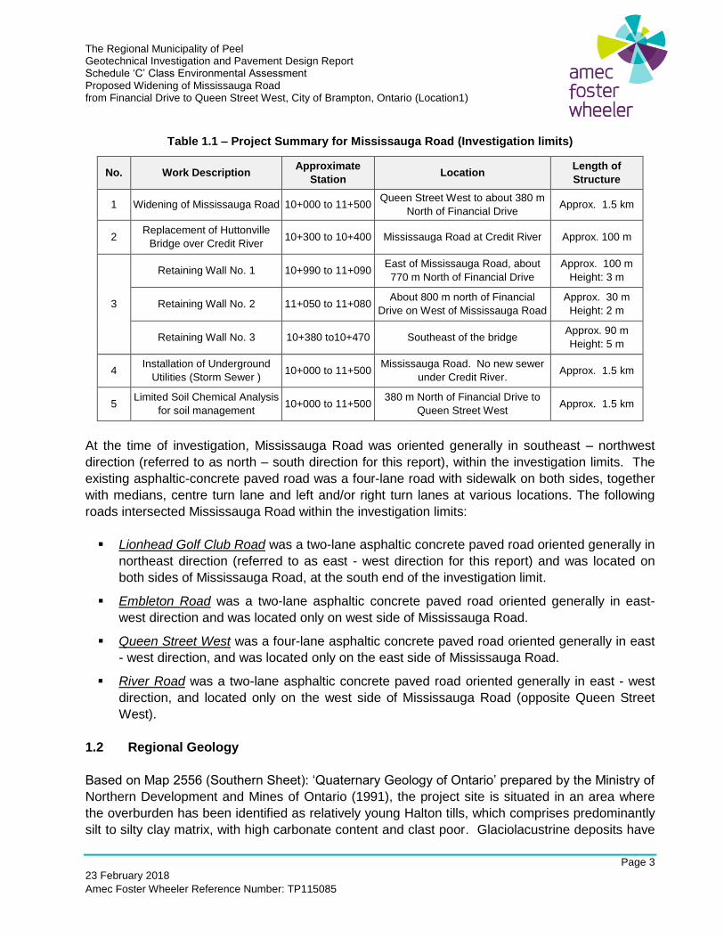
Table 1.1 – Project Summary for Mississauga Road (Investigation limits)
No. Work Description Approximate
Station Location
Length of
Structure
1 Widening of Mississauga Road 10+000 to 11+500 Queen Street West to about 380 m
North of Financial Drive Approx. 1.5 km
2 Replacement of Huttonville
Bridge over Credit River 10+300 to 10+400 Mississauga Road at Credit River Approx. 100 m
3
Retaining Wall No. 1 10+990 to 11+090 East of Mississauga Road, about
770 m North of Financial Drive
Approx. 100 m
Height: 3 m
Retaining Wall No. 2 11+050 to 11+080 About 800 m north of Financial
Drive on West of Mississauga Road
Approx. 30 m
Height: 2 m
Retaining Wall No. 3 10+380 to10+470 Southeast of the bridge Approx. 90 m
Height: 5 m
4 Installation of Underground
Utilities (Storm Sewer ) 10+000 to 11+500
Mississauga Road. No new sewer
under Credit River. Approx. 1.5 km
5 Limited Soil Chemical Analysis
for soil management 10+000 to 11+500
380 m North of Financial Drive to
Queen Street West Approx. 1.5 km
At the time of investigation, Mississauga Road was oriented generally in southeast – northwest
direction (referred to as north – south direction for this report), within the investigation limits. The
existing asphaltic-concrete paved road was a four-lane road with sidewalk on both sides, together
with medians, centre turn lane and left and/or right turn lanes at various locations. The following
roads intersected Mississauga Road within the investigation limits:
▪ Lionhead Golf Club Road was a two-lane asphaltic concrete paved road oriented generally in
northeast direction (referred to as east - west direction for this report) and was located on
both sides of Mississauga Road, at the south end of the investigation limit.
▪ Embleton Road was a two-lane asphaltic concrete paved road oriented generally in east-
west direction and was located only on west side of Mississauga Road.
▪ Queen Street West was a four-lane asphaltic concrete paved road oriented generally in east
- west direction, and was located only on the east side of Mississauga Road.
▪ River Road was a two-lane asphaltic concrete paved road oriented generally in east - west
direction, and located only on the west side of Mississauga Road (opposite Queen Street
West).
1.2 Regional Geology
Based on Map 2556 (Southern Sheet): ‘Quaternary Geology of Ontario’ prepared by the Ministry of
Northern Development and Mines of Ontario (1991), the project site is situated in an area where
the overburden has been identified as relatively young Halton tills, which comprises predominantly
silt to silty clay matrix, with high carbonate content and clast poor. Glaciolacustrine deposits have

The Regional Municipality of Peel Geotechnical Investigation and Pavement Design Report Schedule ‘C’ Class Environmental Assessment Proposed Widening of Mississauga Road from Financial Drive to Queen Street West, City of Brampton, Ontario (Location1)
Page 4
23 February 2018
Amec Foster Wheeler Reference Number: TP115085
also been identified within the project site and characterized by silt and clay, sand, gravelly sand
and gravel basin, nearshore and quiet water deposits.
Based on Map 2544 (Southern Sheet): ‘Bedrock Geology of Ontario’ prepared by the Ministry of
Northern Development and Mines of Ontario (1991), the bedrock underlying the overburden at the
project site is the Queenston Formation which comprises shale, dolostone, limestone and siltstone.
2.0 INVESTIGATION PROCEDURE
Based on the Terms of Reference (‘TOR’) for geotechnical investigation, the following tasks were
carried out:
► Geotechnical investigation for:
o road widening;
o bridge widening;
o retaining walls; and
o underground utilities.
► Pavement investigation:
o Visual pavement condition survey of existing road;
o Falling Weight Deflectometer (FWD) survey; and
o Borehole investigation for existing pavement.
► Laboratory testing for soil classification, including soil chemical analyses; and
► Installation of monitoring wells for hydrogeological investigation (reported in a separate
cover).
The geotechnical investigation obtained information on the subsurface conditions at the site by
means of sampled boreholes. A total of 48 boreholes were drilled along Mississauga Road during
this investigation, which included:
▪ forty (40) boreholes for pavement widening / underground utilities (BH 1 to BH 42, except
BH 34* and BH 37*);
▪ six (6) boreholes for bridge widening (BH B1 to BH B6); and
▪ two (2) boreholes (BH R1 and BH R2) for Retaining Wall No. 1.
* As the borehole locations were close to each other, Boreholes BH B1 and BH 37 were drilled at the same
location, and similarly, Boreholes BH B3 and BH 34 were drilled at the same location. Both BH B1 and BH B3
were drilled deeper than the borehole depth planned for BH 37 and BH 34. BH 37 and BH 34 are not referred
hereinafter.
The Regional Municipality of Peel Geotechnical Investigation and Pavement Design Report Schedule ‘C’ Class Environmental Assessment Proposed Widening of Mississauga Road from Financial Drive to Queen Street West, City of Brampton, Ontario (Location1)
Page 5
23 February 2018
Amec Foster Wheeler Reference Number: TP115085
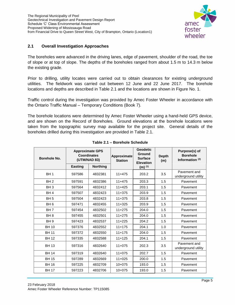
2.1 Overall Investigation Approaches
The boreholes were advanced in the driving lanes, edge of pavement, shoulder of the road, the toe
of slope or at top of slope. The depths of the boreholes ranged from about 1.5 m to 14.3 m below
the existing grade.
Prior to drilling, utility locates were carried out to obtain clearances for existing underground
utilities. The fieldwork was carried out between 12 June and 22 June 2017. The borehole
locations and depths are described in Table 2.1 and the locations are shown in Figure No. 1.
Traffic control during the investigation was provided by Amec Foster Wheeler in accordance with
the Ontario Traffic Manual – Temporary Conditions (Book 7).
The borehole locations were determined by Amec Foster Wheeler using a hand-held GPS device,
and are shown on the Record of Boreholes. Ground elevations at the borehole locations were
taken from the topographic survey map available for the project site. General details of the
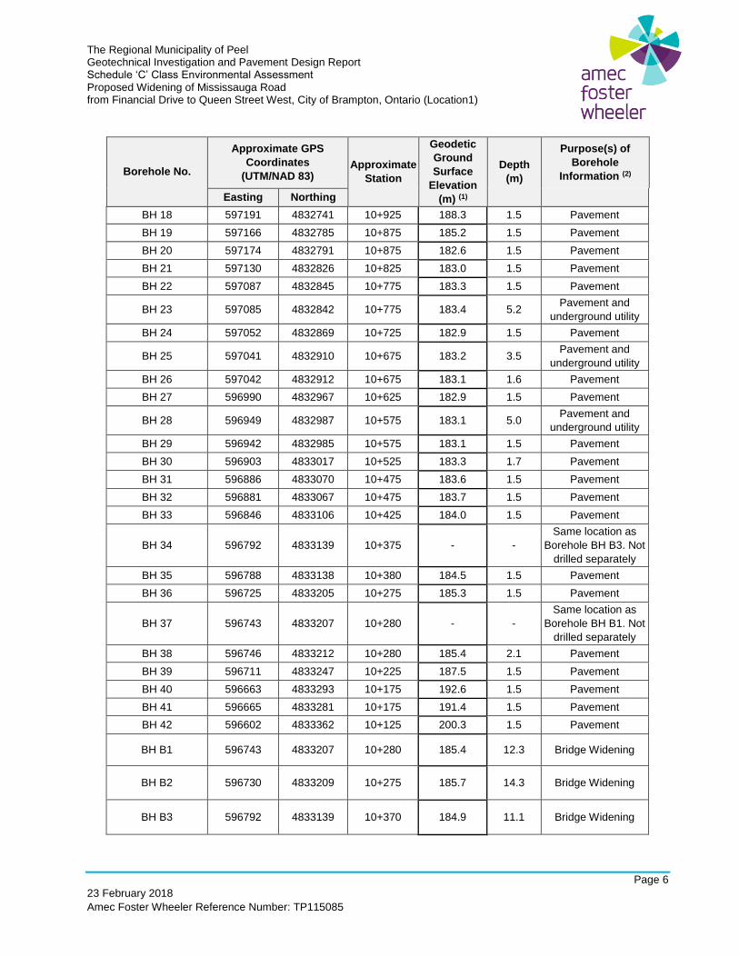
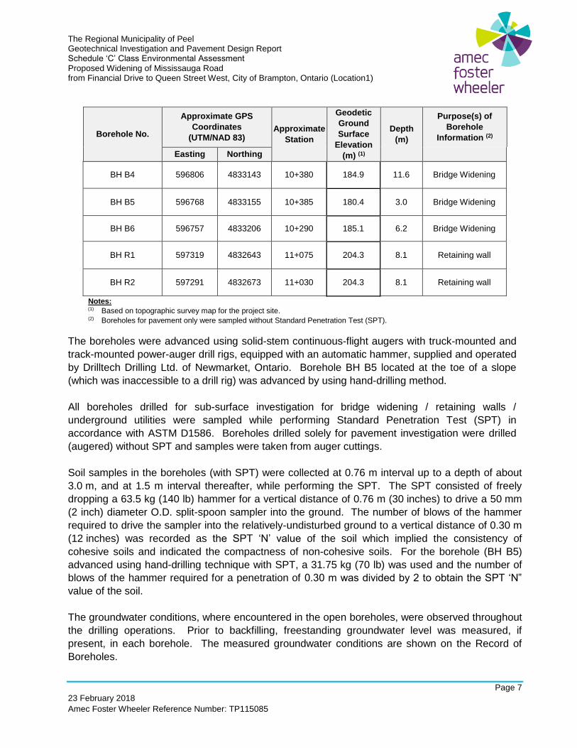
boreholes drilled during this investigation are provided in Table 2.1.
Table 2.1 – Borehole Schedule
Borehole No.
Approximate GPS
Coordinates
(UTM/NAD 83) Approximate
Station
Geodetic
Ground
Surface
Elevation
(m) (1)
Depth
(m)
Purpose(s) of
Borehole
Information (2)
Easting Northing
BH 1 597586 4832381 11+475 203.2 3.5 Pavement and
underground utility
BH 2 597591 4832386 11+475 203.3 1.5 Pavement
BH 3 597564 4832412 11+425 203.1 1.5 Pavement
BH 4 597507 4832423 11+375 203.9 1.5 Pavement
BH 5 597504 4832423 11+375 203.8 1.5 Pavement
BH 6 597471 4832455 11+325 203.9 1.5 Pavement
BH 7 597454 4832502 11+275 204.0 1.5 Pavement
BH 8 597455 4832501 11+275 204.0 1.5 Pavement
BH 9 597423 4832537 11+225 204.2 1.5 Pavement
BH 10 597376 4832552 11+175 204.1 1.0 Pavement
BH 11 597372 4832550 11+175 204.0 1.5 Pavement
BH 12 597335 4832588 11+125 204.1 1.5 Pavement
BH 13 597316 4832640 11+075 202.3 3.5 Pavement and
underground utility
BH 14 597319 4832640 11+075 202.7 1.5 Pavement
BH 15 597289 4832669 11+025 200.0 1.5 Pavement
BH 16 597225 4832709 10+075 193.0 1.5 Pavement
BH 17 597223 4832706 10+075 193.0 1.5 Pavement
The Regional Municipality of Peel Geotechnical Investigation and Pavement Design Report Schedule ‘C’ Class Environmental Assessment Proposed Widening of Mississauga Road from Financial Drive to Queen Street West, City of Brampton, Ontario (Location1)
Page 6
23 February 2018
Amec Foster Wheeler Reference Number: TP115085
Borehole No.
Approximate GPS
Coordinates
(UTM/NAD 83) Approximate
Station
Geodetic
Ground
Surface
Elevation
(m) (1)
Depth
(m)
Purpose(s) of
Borehole
Information (2)
Easting Northing
BH 18 597191 4832741 10+925 188.3 1.5 Pavement
BH 19 597166 4832785 10+875 185.2 1.5 Pavement
BH 20 597174 4832791 10+875 182.6 1.5 Pavement
BH 21 597130 4832826 10+825 183.0 1.5 Pavement
BH 22 597087 4832845 10+775 183.3 1.5 Pavement
BH 23 597085 4832842 10+775 183.4 5.2 Pavement and
underground utility
BH 24 597052 4832869 10+725 182.9 1.5 Pavement
BH 25 597041 4832910 10+675 183.2 3.5 Pavement and
underground utility
BH 26 597042 4832912 10+675 183.1 1.6 Pavement
BH 27 596990 4832967 10+625 182.9 1.5 Pavement
BH 28 596949 4832987 10+575 183.1 5.0 Pavement and
underground utility
BH 29 596942 4832985 10+575 183.1 1.5 Pavement
BH 30 596903 4833017 10+525 183.3 1.7 Pavement
BH 31 596886 4833070 10+475 183.6 1.5 Pavement
BH 32 596881 4833067 10+475 183.7 1.5 Pavement
BH 33 596846 4833106 10+425 184.0 1.5 Pavement
BH 34 596792 4833139 10+375 - -
Same location as
Borehole BH B3. Not
drilled separately
BH 35 596788 4833138 10+380 184.5 1.5 Pavement
BH 36 596725 4833205 10+275 185.3 1.5 Pavement
BH 37 596743 4833207 10+280 - -
Same location as
Borehole BH B1. Not
drilled separately
BH 38 596746 4833212 10+280 185.4 2.1 Pavement
BH 39 596711 4833247 10+225 187.5 1.5 Pavement
BH 40 596663 4833293 10+175 192.6 1.5 Pavement
BH 41 596665 4833281 10+175 191.4 1.5 Pavement
BH 42 596602 4833362 10+125 200.3 1.5 Pavement
BH B1 596743 4833207 10+280 185.4 12.3 Bridge Widening
BH B2 596730 4833209 10+275 185.7 14.3 Bridge Widening
BH B3 596792 4833139 10+370 184.9 11.1 Bridge Widening
The Regional Municipality of Peel Geotechnical Investigation and Pavement Design Report Schedule ‘C’ Class Environmental Assessment Proposed Widening of Mississauga Road from Financial Drive to Queen Street West, City of Brampton, Ontario (Location1)
Page 7
23 February 2018
Amec Foster Wheeler Reference Number: TP115085
Borehole No.
Approximate GPS
Coordinates
(UTM/NAD 83) Approximate
Station
Geodetic
Ground
Surface
Elevation
(m) (1)
Depth
(m)
Purpose(s) of
Borehole
Information (2)
Easting Northing
BH B4 596806 4833143 10+380 184.9 11.6 Bridge Widening
BH B5 596768 4833155 10+385 180.4 3.0 Bridge Widening
BH B6 596757 4833206 10+290 185.1 6.2 Bridge Widening
BH R1 597319 4832643 11+075 204.3 8.1 Retaining wall
BH R2 597291 4832673 11+030 204.3 8.1 Retaining wall
Notes: (1) Based on topographic survey map for the project site. (2) Boreholes for pavement only were sampled without Standard Penetration Test (SPT).
The boreholes were advanced using solid-stem continuous-flight augers with truck-mounted and
track-mounted power-auger drill rigs, equipped with an automatic hammer, supplied and operated
by Drilltech Drilling Ltd. of Newmarket, Ontario. Borehole BH B5 located at the toe of a slope
(which was inaccessible to a drill rig) was advanced by using hand-drilling method.
All boreholes drilled for sub-surface investigation for bridge widening / retaining walls /
underground utilities were sampled while performing Standard Penetration Test (SPT) in
accordance with ASTM D1586. Boreholes drilled solely for pavement investigation were drilled
(augered) without SPT and samples were taken from auger cuttings.
Soil samples in the boreholes (with SPT) were collected at 0.76 m interval up to a depth of about
3.0 m, and at 1.5 m interval thereafter, while performing the SPT. The SPT consisted of freely
dropping a 63.5 kg (140 lb) hammer for a vertical distance of 0.76 m (30 inches) to drive a 50 mm
(2 inch) diameter O.D. split-spoon sampler into the ground. The number of blows of the hammer
required to drive the sampler into the relatively-undisturbed ground to a vertical distance of 0.30 m
(12 inches) was recorded as the SPT ‘N’ value of the soil which implied the consistency of
cohesive soils and indicated the compactness of non-cohesive soils. For the borehole (BH B5)
advanced using hand-drilling technique with SPT, a 31.75 kg (70 lb) was used and the number of
blows of the hammer required for a penetration of 0.30 m was divided by 2 to obtain the SPT ‘N”
value of the soil.
The groundwater conditions, where encountered in the open boreholes, were observed throughout
the drilling operations. Prior to backfilling, freestanding groundwater level was measured, if
present, in each borehole. The measured groundwater conditions are shown on the Record of
Boreholes.
The Regional Municipality of Peel Geotechnical Investigation and Pavement Design Report Schedule ‘C’ Class Environmental Assessment Proposed Widening of Mississauga Road from Financial Drive to Queen Street West, City of Brampton, Ontario (Location1)
Page 8
23 February 2018
Amec Foster Wheeler Reference Number: TP115085
A monitoring well was installed in two boreholes (BH B3 and BH B4) for hydrogeological
investigation, the findings of which are presented in a separate report.
Upon completion of drilling, the boreholes without monitoring well were backfilled in accordance
with the general requirements of Ontario Regulation 903.
A visual pavement condition survey of the existing road surface was carried out to evaluate the
existing condition. Falling Weight Deflectometer (FWD) tests were performed to evaluate the
current structural capacity of the existing pavement structure. Exp Services Incorporated ('Exp')
was retained by Amec Foster Wheeler to conduct the FWD tests and provide analysis. Selected
photographs showing the existing road condition and the results of FWD tests are included in
Appendix A.
Soil samples were transported to Amec Foster Wheeler’s Advanced Soil Laboratory in
Scarborough for further review and laboratory testing (i.e., water content determination, grain size
distribution analysis and Atterberg Limit test, where applicable). The soil conditions, groundwater
levels, and the results of the in-situ and laboratory tests are presented on the corresponding
Record of Boreholes. The laboratory test results are presented in Appendix B.
Upon recovery, selected soil samples were screened to assess for evidence of potential
contamination, which included visual inspections. Samples were tested in the field for combustible
gases using a portable detector (RKI Eagle 2). The results are presented on the Record of
Boreholes. Selected soil samples were transported to AGAT laboratories, an accredited CAEL
laboratory located in Mississauga for soil chemical analysis. The Certificates of Analyses for the
soil chemical analyses are included in Appendix C.
Two (2) selected soil samples were submitted to AGAT Laboratories for corrosivity analysis (pH,
soluble chloride, soluble sulphate, electrical conductivity and resistivity). The laboratory Certificates
of Analysis are included in Appendix C.
2.2 Geotechnical Investigation
The boreholes drilled specifically for each planned work / structure are addressed in this section. All boreholes drilled are listed in Tables 2.1 and 2.3. 2.2.1 Road Widening
The investigation program for road widening is described in Section 2.3 (Pavement Investigation).
The Regional Municipality of Peel Geotechnical Investigation and Pavement Design Report Schedule ‘C’ Class Environmental Assessment Proposed Widening of Mississauga Road from Financial Drive to Queen Street West, City of Brampton, Ontario (Location1)
Page 9
23 February 2018
Amec Foster Wheeler Reference Number: TP115085
2.2.2 Bridge Widening
Six (6) boreholes (BH B1 to BH B6) as listed in Table 2.1 were drilled in the vicinity of the existing
bridge over Credit River to obtain subsurface information for the proposed widening of the bridge.
2.2.3 Retaining Walls
Two (2) boreholes (BH R1 and BH R2) were drilled at the planned location of Retaining Wall No. 1
(Figure No. 1) to obtain subsurface information for design. The boreholes were drilled from the
top of the existing slope (within the road right-of-way). For the planned Retaining Wall Nos. 2 and
3, the subsurface information from the boreholes located closest to the retaining wall alignments
were utilized as listed in Table 2.2.
Table 2.2 - Boreholes for Retaining Wall Design
Structure Approximate
Station
Approximate
Retaining Wall
Height
(m)
Approximate
Retaining Wall
Length
(m)
Borehole Number
Retaining Wall No. 1 10+990 to 11+090 3 100 BH R1 and BH R2
Retaining Wall No. 2 11+050 to 11+080 2 30 BH 13, BH 14
Retaining Wall No. 3 10+380 to 10+470 5 to 6 90 BH B5 (TOS), BH B4, BH 33,
BH 32, BH 31
2.2.4 Underground Utilities
A total of five (5) boreholes (BH 1, BH 13, BH 23, BH 25 and BH 28) were drilled to depths varying
from 3.5 m to 5.0 m to obtain additional subsurface information for installation / replacement of
underground utilities.
2.3 Pavement Investigation
A total of forty (40) boreholes (BH 1 to BH 42, except BH 34 and BH 37) were drilled for pavement
investigation to depths ranging from 1.0 to 2.1 m below existing grade. As noted in Table 2.1, due
to proximity to Boreholes BH B3 and BH B1, Boreholes BH 34 and BH 37 were not drilled
separately. The pavement boreholes were drilled approximately at 50 m spacing on alternating
sides of road centerline in pairs, consisting of one borehole on mid-driving lane (MDL) or edge of
pavement (EP), and one borehole on mid-shoulder (MSH) or shoulder rounding (SHR) or toe of
slope (TOS). The borehole locations on the road sections and depths are presented in Table 2.3
and the borehole locations are shown in Figure No. 1.
The Regional Municipality of Peel Geotechnical Investigation and Pavement Design Report Schedule ‘C’ Class Environmental Assessment Proposed Widening of Mississauga Road from Financial Drive to Queen Street West, City of Brampton, Ontario (Location1)
Page 10
23 February 2018
Amec Foster Wheeler Reference Number: TP115085
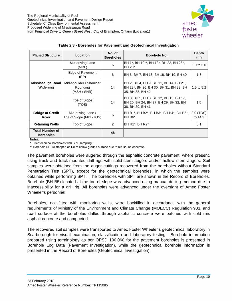
Table 2.3 - Boreholes for Pavement and Geotechnical Investigation
Planed Structure Location No. of
Boreholes Borehole No.
Depth
(m)
Mississauga Road
Widening
Mid-driving Lane
(MDL) 6
BH 1*, BH 10**, BH 13*, BH 22, BH 25*,
BH 28* 1.0 to 5.0
Edge of Pavement
(EP) 6 BH 6, BH 7, BH 16, BH 18, BH 19, BH 40 1.5
Mid-shoulder / Shoulder
Rounding
(MSH / SHR)
14
BH 2, BH 4, BH 9, BH 11, BH 14, BH 21,
BH 23*, BH 26, BH 30, BH 31, BH 33, BH
35, BH 38, BH 42
1.5 to 5.2
Toe of Slope
(TOS) 14
BH 3, BH 5, BH 8, BH 12, BH 15, BH 17,
BH 20, BH 24, BH 27, BH 29, BH 32, BH
36, BH 39, BH 41
1.5
Bridge at Credit
River
Mid-driving Lane /
Toe of Slope (MDL/TOS) 6
BH B1*, BH B2*, BH B3*, BH B4*, BH B5*,
BH B6*
3.0 (TOS)
to 14.3
Retaining Walls Top of Slope 2 BH R1*, BH R2* 8.1
Total Number of
Boreholes 48
Notes:
* Geotechnical boreholes with SPT sampling.
** Borehole BH 10 stopped at 1.0 m below ground surface due to refusal on concrete.
The pavement boreholes were augered through the asphaltic concrete pavement, where present,
using truck and track-mounted drill rigs with solid-stem augers and/or hollow stem augers. Soil
samples were obtained from the auger cuttings recovered from the boreholes without Standard
Penetration Test (SPT), except for the geotechnical boreholes, in which the samples were
obtained while performing SPT. The boreholes with SPT are shown in the Record of Boreholes.
Borehole (BH B5) located at the toe of slope was advanced using manual drilling method due to
inaccessibility for a drill rig. All boreholes were advanced under the oversight of Amec Foster
Wheeler's personnel.
Boreholes, not fitted with monitoring wells, were backfilled in accordance with the general
requirements of Ministry of the Environment and Climate Change (MOECC) Regulation 903, and
road surface at the boreholes drilled through asphaltic concrete were patched with cold mix
asphalt concrete and compacted.
The recovered soil samples were transported to Amec Foster Wheeler’s geotechnical laboratory in
Scarborough for visual examination, classification and laboratory testing. Borehole information
prepared using terminology as per OPSD 100.060 for the pavement boreholes is presented in
Borehole Log Data (Pavement Investigation), while the geotechnical borehole information is
presented in the Record of Boreholes (Geotechnical Investigation).
The Regional Municipality of Peel Geotechnical Investigation and Pavement Design Report Schedule ‘C’ Class Environmental Assessment Proposed Widening of Mississauga Road from Financial Drive to Queen Street West, City of Brampton, Ontario (Location1)
Page 11
23 February 2018
Amec Foster Wheeler Reference Number: TP115085
3.0 ROAD WIDENING
Mississauga Road is proposed to be widened from the existing 4-lane road to a 6-lane road, with
one additional lane (about 4 m wide) in each direction, within the investigation limits. The road
widening will include cut and fill areas, with embankment height up to a maximum of about 6 m,
and cut slope height up to a maximum of about 4 m.
A total 40 boreholes were drilled along alignment within the investigation limits to investigate the
sub-surface and pavement structure condition, out of which five (5) of the boreholes (BH 1, BH 13,
BH 23, BH 25 and BH 28) were drilled deeper (3.5 m to 5.2 m deep) than the rest of the boreholes,
which were drilled to a depth of about 1.5 m for pavement investigation. SPT was carried out in
the deeper boreholes, while the shallower boreholes were sampled from auger cutting (without
SPT).
Additional boreholes drilled were for bridge foundations (BH B1 to B6) and retaining walls (BH R1
and BH R2). Bridge foundation and retaining walls are discussed Section 4.0 (Bridge over Credit
River) and Sections 5.0 to 7.0 (Retaining Wall Nos. 1 to 3), respectively.
Proposed widening work may include installation of new underground utilities (storm sewer) and /
or replacement of existing underground utilities, which is discussed in Section 8.0.
Pavement design is discussed in Section 10.0 (Pavement Investigation and Design).
The sub-surface conditions and geotechnical recommendations for road widening are discussed in
the following sections.
3.1 Sub-surface Conditions
Based on the soil conditions encountered in the deeper boreholes drilled along the road alignment
(BH 1, BH 13, BH 23, BH 25, BH 28, BH B1 (for BH 37) and BH B3 (for BH 34)), fill soils (sand and
gravel, gravelly sand, sand, silty sand, sandy clayey silt, silty clay/clayey silt) were encountered
below the surficial asphaltic concrete. The fill soils were underlain by natural deposits of sand and
gravel, sandy gravel, sand, silty sand / sandy silt, silty sand / sandy silt till, silty clay / clayey silt till
and/or weather shale. Weathered shale was encountered in BH B3 at a depth of about 10.7 m,
but is not relevant for road widening. Groundwater was encountered in all boreholes upon
completion of drilling, except in Borehole BH 13 which was dry.
The stratigraphic units and groundwater conditions are discussed in the following sections, and are
presented in the Record of Boreholes. The following summary is to assist the designers of the
project with an understanding of the soil conditions encountered at the investigated road section.
The soil and groundwater conditions may vary between and beyond the borehole locations.
The Regional Municipality of Peel Geotechnical Investigation and Pavement Design Report Schedule ‘C’ Class Environmental Assessment Proposed Widening of Mississauga Road from Financial Drive to Queen Street West, City of Brampton, Ontario (Location1)
Page 12
23 February 2018
Amec Foster Wheeler Reference Number: TP115085
3.1.1 Asphaltic Concrete
The boreholes were generally drilled through the existing paved driving lanes, except Borehole BH
23 which was drilled on the shoulder. Asphaltic concrete encountered at the borehole locations
varied in thickness from about 100 mm to 200 mm.
3.1.2 Fill Soils
Fill soils were encountered in all boreholes to depths varying from 2.1 m in BH 1 to the maximum
depth of 5.6 m in Boreholes BH B1 and BH B3. The fill soils generally consisted of sand and
gravel, gravelly sand, sand, silty sand fill (“non-cohesive fill”) and/or sandy clayey silt, silty
clay/clayey silt fill (“cohesive fill”).
The non-cohesive fill was brown, dark brown, reddish brown and grey in colour, and contained
trace to some clay, trace cobbles, with organic matter / wood chips / silty clay pockets. SPT ‘N’
values measured within the non-cohesive fill varied from 1 to over 50 blows per 0.3 m. Water
contents measured in the non-cohesive fill samples varied from 3 % to 13 %.
The cohesive fill was brown in colour and contained trace gravel, with sand pockets. SPT ‘N’
values measured within the cohesive fill were 7 and 20 blows per 0.3 m. Water contents
measured in the cohesive fill samples were 13 % and 15 %.
3.1.3 Silty Sand / Sandy Silt / Sand
Natural deposit of silty sand / sandy silt / sand was encountered in Boreholes BH 1, BH 13, BH 23
and BH B1, underlying the fill soils, and extended to depths ranging approximately from 3.0 m to
11.5 in Boreholes BH 23 and BH B1, respectively and to the termination depth of 3.5 m below the
existing ground surface in Boreholes BH 1 and BH 13.
The silty sand / sandy silt / sand was brown, reddish brown and/or brownish grey in colour, and
contained trace to some clay, some gravel, trace cobbles, with organic matter. SPT ‘N’ values
measured in the silty sand / sandy silt / sand ranged from 9 to more than 50 blows per 0.3 m,
indicating loose to very dense compactness. Water contents measured in the silty sand / sandy
silt / sand were 11 % and 14 %.
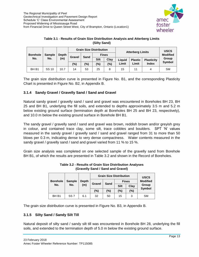
Grain size analysis and Atterberg Limit test were completed on one selected sample of the silty
sand from Borehole BH B1, the results of which are presented in Table 3.1 and shown in the
Record of Boreholes.
The Regional Municipality of Peel Geotechnical Investigation and Pavement Design Report Schedule ‘C’ Class Environmental Assessment Proposed Widening of Mississauga Road from Financial Drive to Queen Street West, City of Brampton, Ontario (Location1)
Page 13
23 February 2018
Amec Foster Wheeler Reference Number: TP115085
Table 3.1 - Results of Grain Size Distribution Analysis and Atterberg Limits
(Silty Sand)
Borehole
No.
Sample
No.
Depth
(m)
Grain Size Distribution Atterberg Limits USCS
Modified
Group
Symbol
Gravel Sand Fines
Silt Clay Liquid
Limit
Plastic
Limit
Plasticity
Index (%) (%) (%) (%)
BH B1 SS 10 10.7 14 53 25 8 15 11 4 SM
The grain size distribution curve is presented in Figure No. B1, and the corresponding Plasticity
Chart is presented in Figure No. B2, in Appendix B.
3.1.4 Sandy Gravel / Gravelly Sand / Sand and Gravel
Natural sandy gravel / gravelly sand / sand and gravel was encountered in Boreholes BH 23, BH
25 and BH B1, underlying the fill soils, and extended to depths approximately 3.5 m and 5.2 m
below existing ground surface (termination depth at Boreholes BH 25 and BH 23, respectively),
and 10.0 m below the existing ground surface in Borehole BH B1.
The sandy gravel / gravelly sand / sand and gravel was brown, reddish brown and/or greyish grey
in colour, and contained trace clay, some silt, trace cobbles and boulders. SPT ‘N’ values
measured in the sandy gravel / gravelly sand / sand and gravel ranged from 31 to more than 50
blows per 0.3 m, indicating dense to very dense compactness. Water contents measured in the
sandy gravel / gravelly sand / sand and gravel varied from 11 % to 15 %.
Grain size analysis was completed on one selected sample of the gravelly sand from Borehole
BH B1, of which the results are presented in Table 3.2 and shown in the Record of Boreholes.
Table 3.2 - Results of Grain Size Distribution Analyses
(Gravelly Sand / Sand and Gravel)
Borehole
No.
Sample
No.
Depth
(m)
Grain Size Distribution USCS
Modified
Group
Symbol
Gravel Sand Fines
Silt Clay
(%) (%) (%) (%)
BH B1 SS 7 6.1 32 50 15 3 SM
The grain size distribution curve is presented in Figure No. B3, in Appendix B.
3.1.5 Silty Sand / Sandy Silt Till
Natural deposit of silty sand / sandy silt till was encountered in Borehole BH 28, underlying the fill
soils, and extended to the termination depth of 5.0 m below the existing ground surface.
The Regional Municipality of Peel Geotechnical Investigation and Pavement Design Report Schedule ‘C’ Class Environmental Assessment Proposed Widening of Mississauga Road from Financial Drive to Queen Street West, City of Brampton, Ontario (Location1)
Page 14
23 February 2018
Amec Foster Wheeler Reference Number: TP115085
The silty sand / sandy silt till was greyish brown in colour, and contained trace clay, some gravel to
gravelly, cobbles and boulders. SPT ‘N’ values measured in the silty sand / sandy silt till were
more than 50 blows per 0.3 m, indicating very dense compactness.
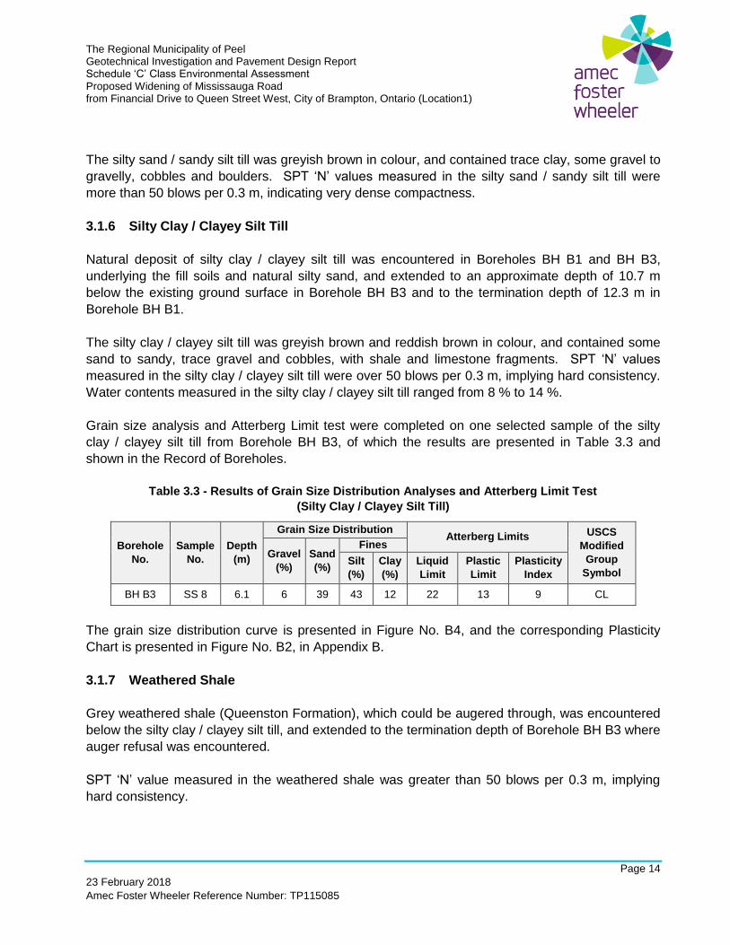
3.1.6 Silty Clay / Clayey Silt Till
Natural deposit of silty clay / clayey silt till was encountered in Boreholes BH B1 and BH B3,
underlying the fill soils and natural silty sand, and extended to an approximate depth of 10.7 m
below the existing ground surface in Borehole BH B3 and to the termination depth of 12.3 m in
Borehole BH B1.
The silty clay / clayey silt till was greyish brown and reddish brown in colour, and contained some
sand to sandy, trace gravel and cobbles, with shale and limestone fragments. SPT ‘N’ values
measured in the silty clay / clayey silt till were over 50 blows per 0.3 m, implying hard consistency.
Water contents measured in the silty clay / clayey silt till ranged from 8 % to 14 %.
Grain size analysis and Atterberg Limit test were completed on one selected sample of the silty
clay / clayey silt till from Borehole BH B3, of which the results are presented in Table 3.3 and
shown in the Record of Boreholes.
Table 3.3 - Results of Grain Size Distribution Analyses and Atterberg Limit Test
(Silty Clay / Clayey Silt Till)
Borehole
No.
Sample
No.
Depth
(m)
Grain Size Distribution Atterberg Limits USCS
Modified
Group
Symbol
Gravel
(%)
Sand
(%)
Fines
Silt
(%)
Clay
(%)
Liquid
Limit
Plastic
Limit
Plasticity
Index
BH B3 SS 8 6.1 6 39 43 12 22 13 9 CL
The grain size distribution curve is presented in Figure No. B4, and the corresponding Plasticity
Chart is presented in Figure No. B2, in Appendix B.
3.1.7 Weathered Shale
Grey weathered shale (Queenston Formation), which could be augered through, was encountered
below the silty clay / clayey silt till, and extended to the termination depth of Borehole BH B3 where
auger refusal was encountered.
SPT ‘N’ value measured in the weathered shale was greater than 50 blows per 0.3 m, implying
hard consistency.
The Regional Municipality of Peel Geotechnical Investigation and Pavement Design Report Schedule ‘C’ Class Environmental Assessment Proposed Widening of Mississauga Road from Financial Drive to Queen Street West, City of Brampton, Ontario (Location1)
Page 15
23 February 2018
Amec Foster Wheeler Reference Number: TP115085
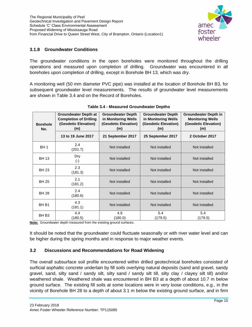
3.1.8 Groundwater Conditions
The groundwater conditions in the open boreholes were monitored throughout the drilling
operations and measured upon completion of drilling. Groundwater was encountered in all
boreholes upon completion of drilling, except in Borehole BH 13, which was dry.
A monitoring well (50 mm diameter PVC pipe) was installed at the location of Borehole BH B3, for
subsequent groundwater level measurements. The results of groundwater level measurements
are shown in Table 3.4 and on the Record of Boreholes.
Table 3.4 - Measured Groundwater Depths
Borehole
No.
Groundwater Depth at
Completion of Drilling
(Geodetic Elevation)
(m)
Groundwater Depth
in Monitoring Wells
(Geodetic Elevation)
(m)
Groundwater Depth
in Monitoring Wells
(Geodetic Elevation)
(m)
Groundwater Depth in
Monitoring Wells
(Geodetic Elevation)
(m)
13 to 19 June 2017 21 September 2017 25 September 2017 2 October 2017
BH 1 2.4
(201.7) Not installed Not installed Not installed
BH 13 Dry
(-) Not installed Not installed Not installed
BH 23 2.3
(181.3) Not installed Not installed Not installed
BH 25 2.1
(181.2) Not installed Not installed Not installed
BH 28 2.4
(180.6) Not installed Not installed Not installed
BH B1 4.3
(181.1) Not installed Not installed Not installed
BH B3 4.4
(180.5)
4.9
(180.0)
5.4
(179.5)
5.4
(179.5)
Note: Groundwater depth measured from the existing ground surfaces.
It should be noted that the groundwater could fluctuate seasonally or with river water level and can
be higher during the spring months and in response to major weather events.
3.2 Discussions and Recommendations for Road Widening
The overall subsurface soil profile encountered within drilled geotechnical boreholes consisted of
surficial asphaltic concrete underlain by fill soils overlying natural deposits (sand and gravel, sandy
gravel, sand, silty sand / sandy silt, silty sand / sandy silt till, silty clay / clayey silt till) and/or
weathered shale. Weathered shale was encountered in BH B3 at a depth of about 10.7 m below
ground surface. The existing fill soils at some locations were in very loose conditions, e.g., in the
vicinity of Borehole BH 28 to a depth of about 3.1 m below the existing ground surface, and in firm
The Regional Municipality of Peel Geotechnical Investigation and Pavement Design Report Schedule ‘C’ Class Environmental Assessment Proposed Widening of Mississauga Road from Financial Drive to Queen Street West, City of Brampton, Ontario (Location1)
Page 16
23 February 2018
Amec Foster Wheeler Reference Number: TP115085
conditions in the vicinity of Boreholes BH B3 and BH B1 to depths of approximately 4.0 m and
5.6 m, respectively. Groundwater was encountered in all boreholes upon completion of drilling
except in Borehole BH 13, which was dry.
The proposed road widening will involve both fill and cut sections along the investigation limits.
Some road sections will require cut of existing slopes, including construction of a retaining wall,
where the road right-of-way (ROW) does not permit construction of a slope. The embankment /
cut slope heights within the investigation limits vary from 0 m to a maximum of about 6 m, including
at the bridge. Retaining walls are discussed in Sections 5.0 to 7.0.
The embankment required for road widening should be constructed with compacted engineered fill
at 2H:1V (or flatter) side slopes. Similarly, the cut areas should also be constructed at a slope of
2H:1V or flatter, subject to slope stability analysis. If a steeper than 2H:1V slope is required or if
the height of the embankment / cut slope is greater than 4.5 m, slope stability analysis should be
carried out to assess stability of the planned slope.
Generally, underground utilities and manholes / catch basins may be founded on the natural soils
and/or engineered fill (if required). Any loose / soft soils found during construction should be
replaced with engineered fill and/or re-compacted to support road pavement structure and
underground utilities.
3.2.1 Site Preparation for Road Widening
The widening of Mississauga Road from 4 to 6 lanes will require, as a minimum, stripping the
existing ground surface cover (topsoil, asphaltic concrete, vegetation cover, surficial fill soils, etc.)
from the area required for road widening. As per information available, planned widening will
generally be constructed in the same elevation as the existing road surface, except in some
locations. Some cut and fill work would be required, e.g., stripping, cutting into road side slope,
filling up side road ditches. Grading should follow OPSS 206 (Construction Specification for
Grading) or the Region's requirements.
Backfilling, if required, for site grading (e.g., for subgrade raise, replacement of soft soil) should be
placed as engineered fill. Engineered fill may be used to replace soft/incompetent soils and/or
raising grade. Engineered fill should be prepared according to the Region’ standards / contract
specifications. Guidelines for engineered fill are included in Section 11.2.
Grading, backfilling and compacting should be carried out in accordance with Region’s Standards
and / or OPSS 401 (Construction Specification for Trenching, Backfilling and Compacting), OPSS
501 (Construction Specification for Compacting) and / or OPSS 206 (Construction Specification for
Grading), as applicable.
3.2.2 Embankment Widening
The Regional Municipality of Peel Geotechnical Investigation and Pavement Design Report Schedule ‘C’ Class Environmental Assessment Proposed Widening of Mississauga Road from Financial Drive to Queen Street West, City of Brampton, Ontario (Location1)
Page 17
23 February 2018
Amec Foster Wheeler Reference Number: TP115085
The widening work to accommodate new lanes will require filling over existing embankment slope
and beyond. Based on available information, the maximum height of the embankment slope would
be about 6 m, including the area close to the bridge (bridge approach areas). High embankments
were present on the east of road between Station 10+900 to 11+000, and in the vicinity of the
bridge. A retaining wall is planned on the southeast side of the bridge over Credit River (discussed
in Section 7.0). Embankment at the bridge approach areas is described in Section 4.0. The
embankment should be constructed with a side slope of 2H:1V (or flatter).
For the high fill areas (height greater than 4.5 m), additional geotechnical investigation and/or
slope stability analysis may be required. If a slope steeper than 2H:1V is required, slope stability
analysis should be carried out to confirm long term stability of the slope.
Care should be exercised to minimize disturbance to the subgrade during preparation and the
construction of embankment. Widening of existing embankments should be in accordance with
the Region’s requirement and/or OPSD - 208.010 (Benching of Earth Slopes). The embankment
construction should be in accordance with OPSS 501 (Construction Specification for Compacting).
The fill soils used for embankment widening should consist of approved clean fill (e.g., Select
Subgrade Materials - OPSS 1010).
3.2.3 Cut Slope Above Road Surface
The widening work will also require cutting into existing slopes in the section between Station
11+000 to 11+100. Based on available information, the maximum height of the cut slope would be
about 4 m. A high cut area (with maximum existing height about 4 m) is located on the east side of
the road, for which a retaining wall (Retaining Wall No. 1) is planned. Similarly, a new retaining
wall (Retaining Wall No. 2) is planned for the west side of the road (approximate Station 11+050 to
11+080). There is an existing approximately 2 m high gabion retaining wall in this section. The
heights of the planned walls should be constructed to match the ground elevation of the slopes,
where possible. Retaining walls are discussed in Sections 5.0 and 6.0.
New cut areas without retaining walls should be constructed at a slope of 2H:1V or flatter, subject
to slope stability analysis, if the top of the cut slope does not extend beyond the right-of-way.
Otherwise, a retaining wall will be required. The retaining wall should be designed to support the
slope above the wall and the type of retaining wall should consider construction method.
Boreholes may be required to determine the soil conditions for the slope to be retained and slope
stability analysis may be required.
The Regional Municipality of Peel Geotechnical Investigation and Pavement Design Report Schedule ‘C’ Class Environmental Assessment Proposed Widening of Mississauga Road from Financial Drive to Queen Street West, City of Brampton, Ontario (Location1)
Page 18
23 February 2018
Amec Foster Wheeler Reference Number: TP115085
4.0 BRIDGE OVER CREDIT RIVER
The existing bridge (Huttonville Bridge) over Credit River is a three-span concrete structure,
consisting of concrete deck slab placed over girders supported by two piers and abutments. The
existing structure (about 18.3 m wide and 76.9 m long) carries four lanes of Mississauga Road
(two in each direction), with sidewalks on both sides of the bridge. Based on the as-built
drawings, the abutments and piers are founded on spread / strip footings at an approximate
elevation of 177 m to 178 m. The bearing capacity value used for design was not shown on the
as-built drawings. It is to be noted that there is an existing watermain running close to the bridge
foundation along the west side of the bridge, which should be taken into account for the design
and construction of the widening.
The existing bridge is planned to be replaced with a new wider and longer three-span bridge
(about 27.2 m wide and 103.0 long) which will include six lanes (three lanes in each direction),
1.5 m wide shoulder on both sides bridge, a 3.0 m wide sidewalk on the east side and parapet
walls on both sides of the bridge. The existing bridge is planned to be completely demolished.
The road grade at the bridge location is planned to be raised by about 2.0 m (from about Elevation
185 m to about 187 m). The existing piers / abutments will not be used for the new bridge, as the
new piers / abutments are planned to be constructed at different locations.
The geotechnical investigation program conducted consisted of drilling a total of six (6) boreholes
(BH B1 to BH B6) on both sides of the existing bridge location as shown in Figure No. 1. Four
boreholes (BH B1 to BH B4) were drilled to auger refusal from the existing road surface to
termination depths of 11.1 m to 14.3 m. The remaining two boreholes (BH B5 and BH B6) were
drilled at or close to the toe of the existing embankment at the south and north ends of the bridge.
The soil profiles are shown in Record of Boreholes and the laboratory test results are presented in
Appendix B.
The abutments and the piers at the areas to be widened of the structure can be founded on deep
foundation (driven piles or augered cast-in-place caissons) or spread / strip footings. Construction
of spread / strip footings, if founded at similar elevation as the existing bridge, will require
excavation of minimum of about 2 m below river bed at the pier locations, and about 4 m below the
existing ground surface at the abutments. Deep foundations should be founded within the
weathered shale. All foundations for new abutments and piers should be the same type, without
the mixed use of deep and shallow foundations.
Based on the planned footing locations, construction of the piers may require partial diversion of
the river water away from the work zone. A temporary river dyke (or similar) may be used for the
diversion.
The sub-surface conditions and geotechnical recommendations for design and construction of the
bridge footing are discussed in the following sections.
The Regional Municipality of Peel Geotechnical Investigation and Pavement Design Report Schedule ‘C’ Class Environmental Assessment Proposed Widening of Mississauga Road from Financial Drive to Queen Street West, City of Brampton, Ontario (Location1)
Page 19
23 February 2018
Amec Foster Wheeler Reference Number: TP115085
4.1 Sub-surface Conditions
Based on the soil conditions observed in the boreholes drilled for the bridge (BH B1 to BH B6), the
subsurface profile at the bridge location generally consisted of non-cohesive fill (i.e., sand and
gravel, sandy gravel, gravelly sand, sand, silty sand), and/or cohesive fill (i.e., silty clay / clayey
silt, sandy clayey silt), underlying topsoil or asphaltic concrete. Natural sand and gravel, silty clay
/ clayey silt till and/or weathered shale were encountered underlying the fill soils in all boreholes.
The stratigraphic units and groundwater conditions at the bridge location are presented in the
Record of Boreholes (Geotechnical Investigation). The following summary is to assist the
designers of the project with an understanding of the soil conditions encountered at the bridge
location. The soil and groundwater conditions may vary between and beyond the borehole
locations.
4.1.1 Surficial Cover – Asphaltic Concrete
At Boreholes BH B1 to BH B4, which were drilled through the existing pavement, the asphaltic
concrete thickness encountered at the road surface varied from about 150 mm to 300 mm.
4.1.2 Surficial Cover – Topsoil
At Borehole BH B5, 120 mm thick topsoil was encountered below ground surface.
4.1.3 Fill Soils
Fill soils were encountered below the asphaltic concrete, topsoil or at the ground surface. The fill
soils were encountered at the ground surface in Borehole BH B6. The fill soils consisted of non-
cohesive fill (i.e., sand and gravel, sandy gravel, gravelly sand, sand, silty sand), and/or cohesive
fill soils (i.e., silty clay / clayey silt, sandy clayey silt) and extended to depths varying from about
1.8 m below the existing ground surface in Borehole BH B5 to about 5.6 m below ground surface
at Boreholes BH B1 to BH B4 and BH B6.
The non-cohesive fill soils (sand and gravel, sandy gravel, gravelly sand, sand, silty sand fill) were
brown, dark brown, greyish brown and/or reddish brown in colour and contained trace to some
clay, trace cobbles, with silty clay / clayey silt pockets, and rootlets and organic matters in
Borehole BH B5. SPT ‘N’ values measured within the non-cohesive fill ranged from 3 to 50 blows
per 0.3 m. Water contents measured in the non-cohesive fill ranged from 3 % to 13 %.
The cohesive fill (silty clay / clayey silt, sandy clayey silt fill) were brown, dark brown and reddish
brown in color and contained some sand to sandy, with sand pockets. SPT ‘N’ values measured
within the cohesive fill soils ranged from 6 to 20 blows per 0.3 m. Water contents measured in the
cohesive fill soil samples ranged from 13 % to 16 %.
The Regional Municipality of Peel Geotechnical Investigation and Pavement Design Report Schedule ‘C’ Class Environmental Assessment Proposed Widening of Mississauga Road from Financial Drive to Queen Street West, City of Brampton, Ontario (Location1)
Page 20
23 February 2018
Amec Foster Wheeler Reference Number: TP115085
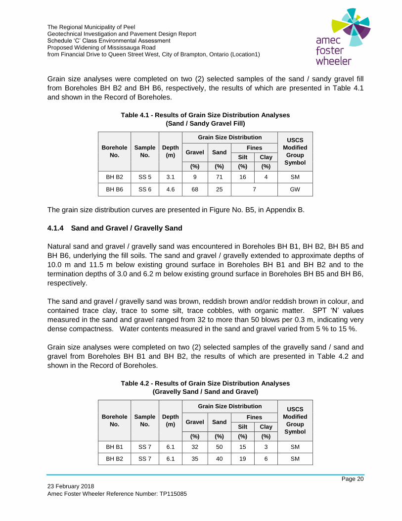
Grain size analyses were completed on two (2) selected samples of the sand / sandy gravel fill
from Boreholes BH B2 and BH B6, respectively, the results of which are presented in Table 4.1
and shown in the Record of Boreholes.
Table 4.1 - Results of Grain Size Distribution Analyses
(Sand / Sandy Gravel Fill)
Borehole
No.
Sample
No.
Depth
(m)
Grain Size Distribution USCS
Modified
Group
Symbol
Gravel Sand Fines
Silt Clay
(%) (%) (%) (%)
BH B2 SS 5 3.1 9 71 16 4 SM
BH B6 SS 6 4.6 68 25 7 GW
The grain size distribution curves are presented in Figure No. B5, in Appendix B.
4.1.4 Sand and Gravel / Gravelly Sand
Natural sand and gravel / gravelly sand was encountered in Boreholes BH B1, BH B2, BH B5 and
BH B6, underlying the fill soils. The sand and gravel / gravelly extended to approximate depths of
10.0 m and 11.5 m below existing ground surface in Boreholes BH B1 and BH B2 and to the
termination depths of 3.0 and 6.2 m below existing ground surface in Boreholes BH B5 and BH B6,
respectively.
The sand and gravel / gravelly sand was brown, reddish brown and/or reddish brown in colour, and
contained trace clay, trace to some silt, trace cobbles, with organic matter. SPT ‘N’ values
measured in the sand and gravel ranged from 32 to more than 50 blows per 0.3 m, indicating very
dense compactness. Water contents measured in the sand and gravel varied from 5 % to 15 %.
Grain size analyses were completed on two (2) selected samples of the gravelly sand / sand and
gravel from Boreholes BH B1 and BH B2, the results of which are presented in Table 4.2 and
shown in the Record of Boreholes.
Table 4.2 - Results of Grain Size Distribution Analyses
(Gravelly Sand / Sand and Gravel)
Borehole
No.
Sample
No.
Depth
(m)
Grain Size Distribution USCS
Modified
Group
Symbol
Gravel Sand Fines
Silt Clay
(%) (%) (%) (%)
BH B1 SS 7 6.1 32 50 15 3 SM
BH B2 SS 7 6.1 35 40 19 6 SM
The Regional Municipality of Peel Geotechnical Investigation and Pavement Design Report Schedule ‘C’ Class Environmental Assessment Proposed Widening of Mississauga Road from Financial Drive to Queen Street West, City of Brampton, Ontario (Location1)
Page 21
23 February 2018
Amec Foster Wheeler Reference Number: TP115085
Grain size distribution curves are presented in Figure No. B3, in Appendix B.
4.1.5 Silty Sand
Natural silty sand deposit was encountered in Borehole BH B1 underlying the sand and gravel,
and extended to an approximate depth of 11.5 m below existing ground surface.
The silty sand was brown and/or brownish grey in colour, and contained trace clay, some gravel,
trace cobbles. A SPT ‘N’ value measured in the silty sand was more than 50 blows per 0.3 m,
indicating a very dense compactness. A water content measured in the silty sand was 11 %.
Grain size analysis and Atterberg Limit test were completed on one selected sample of the silty
sand from Borehole BH B1, the results of which are presented in Table 3.1 (Section 3.1.3) and
shown in the Record of Boreholes.
4.1.6 Silty Clay / Clayey Silt Till
Natural silty clay / clayey silt till was encountered in Boreholes BH B1 to BH B5 underlying the fill
soils and natural silty sand / sand and gravel, and extended to depths varying from about 7.2 m to
13.0 m below existing ground surface in Boreholes BH B2 to BH 4, or to the termination depths in
Boreholes BH B1 and BH B5.
The silty clay / clayey silt till was greyish brown and/or reddish brown in colour, and contained
trace sand to sandy, trace gravel and cobbles, with shale and limestone fragments. SPT ‘N’
values measured within the silty clay / clayey silt till were greater than 50 blows per 0.3 m, implying
hard consistency. Water contents measured in the silty clay / clayey silt till ranged from 7 % to
14 %.
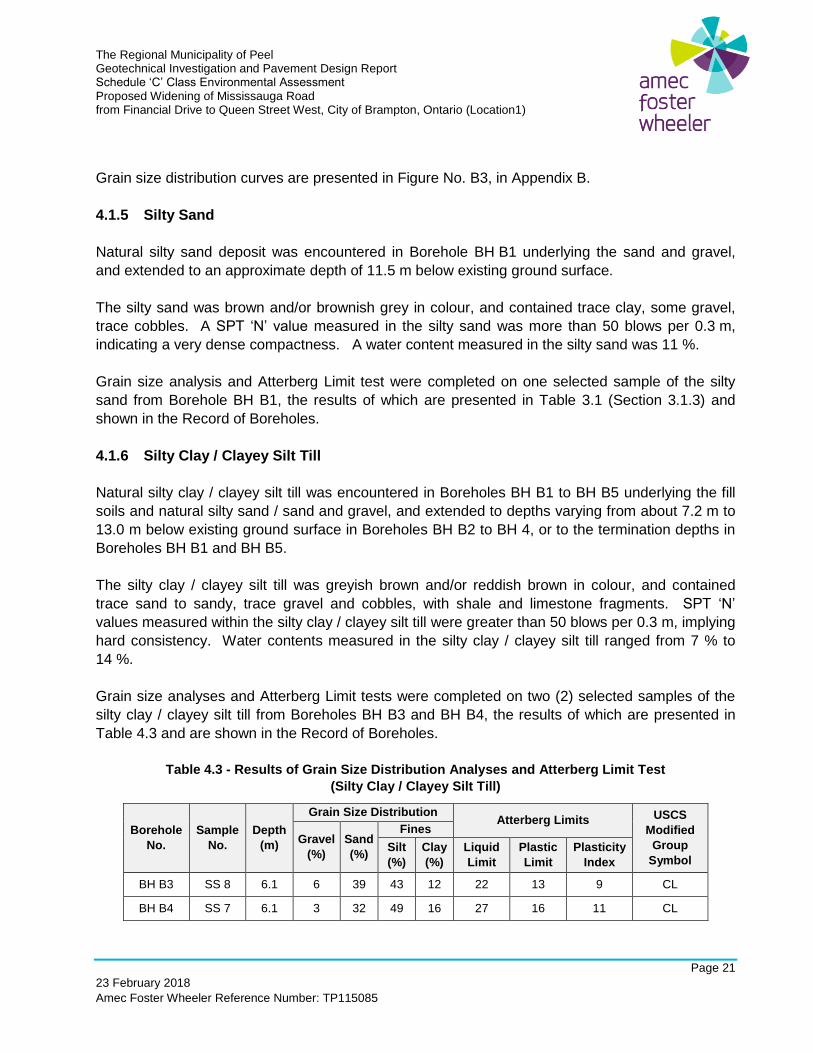
Grain size analyses and Atterberg Limit tests were completed on two (2) selected samples of the
silty clay / clayey silt till from Boreholes BH B3 and BH B4, the results of which are presented in
Table 4.3 and are shown in the Record of Boreholes.
Table 4.3 - Results of Grain Size Distribution Analyses and Atterberg Limit Test
(Silty Clay / Clayey Silt Till)
Borehole
No.
Sample
No.
Depth
(m)
Grain Size Distribution Atterberg Limits USCS
Modified
Group
Symbol
Gravel
(%)
Sand
(%)
Fines
Silt
(%)
Clay
(%)
Liquid
Limit
Plastic
Limit
Plasticity
Index
BH B3 SS 8 6.1 6 39 43 12 22 13 9 CL
BH B4 SS 7 6.1 3 32 49 16 27 16 11 CL
The Regional Municipality of Peel Geotechnical Investigation and Pavement Design Report Schedule ‘C’ Class Environmental Assessment Proposed Widening of Mississauga Road from Financial Drive to Queen Street West, City of Brampton, Ontario (Location1)
Page 22
23 February 2018
Amec Foster Wheeler Reference Number: TP115085
Grain size distribution curves are presented in Figure No. B4, and the corresponding Plasticity
Chart is presented in Figure No. B2, in Appendix B.
4.1.7 Weathered Shale
Weathered shale was encountered below the natural silty clay / clayey silt till, and extended to the
auger-refusal depths in Boreholes BH B2 to BH B4.
The weathered shale was reddish brown and/or grey in colour and contained limestone fragments.
SPT ‘N’-values measured in the weathered shale were greater than 50 blows per 0.3 m, implying
hard consistency. Measured water contents in the weathered shale samples varied from 7 % to
14 %.
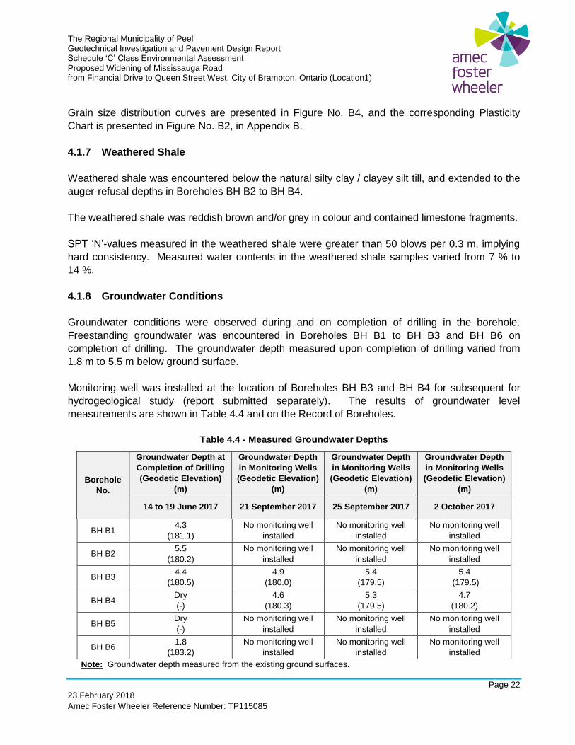
4.1.8 Groundwater Conditions
Groundwater conditions were observed during and on completion of drilling in the borehole.
Freestanding groundwater was encountered in Boreholes BH B1 to BH B3 and BH B6 on
completion of drilling. The groundwater depth measured upon completion of drilling varied from
1.8 m to 5.5 m below ground surface.
Monitoring well was installed at the location of Boreholes BH B3 and BH B4 for subsequent for
hydrogeological study (report submitted separately). The results of groundwater level
measurements are shown in Table 4.4 and on the Record of Boreholes.
Table 4.4 - Measured Groundwater Depths
Borehole
No.
Groundwater Depth at
Completion of Drilling
(Geodetic Elevation)
(m)
Groundwater Depth
in Monitoring Wells
(Geodetic Elevation)
(m)
Groundwater Depth
in Monitoring Wells
(Geodetic Elevation)
(m)
Groundwater Depth
in Monitoring Wells
(Geodetic Elevation)
(m)
14 to 19 June 2017 21 September 2017 25 September 2017 2 October 2017
BH B1 4.3
(181.1)
No monitoring well
installed
No monitoring well
installed
No monitoring well
installed
BH B2 5.5
(180.2)
No monitoring well
installed
No monitoring well
installed
No monitoring well
installed
BH B3 4.4
(180.5)
4.9
(180.0)
5.4
(179.5)
5.4
(179.5)
BH B4 Dry
(-)
4.6
(180.3) 5.3
(179.5) 4.7
(180.2)
BH B5 Dry
(-)
No monitoring well
installed No monitoring well
installed No monitoring well
installed
BH B6 1.8
(183.2)
No monitoring well
installed
No monitoring well
installed
No monitoring well
installed
Note: Groundwater depth measured from the existing ground surfaces.
The Regional Municipality of Peel Geotechnical Investigation and Pavement Design Report Schedule ‘C’ Class Environmental Assessment Proposed Widening of Mississauga Road from Financial Drive to Queen Street West, City of Brampton, Ontario (Location1)
Page 23
23 February 2018
Amec Foster Wheeler Reference Number: TP115085
It should be noted that the groundwater could fluctuate seasonally or with river water level and can
be expected to be somewhat higher during the spring months and in response to major weather
events.
4.2 Discussions and Recommendations for Bridge Widening
Mississauga Road, along with the Huttonville bridge over Credit River, is proposed to be widened
to support six driving lanes. The existing bridge is a three-span structure with concrete deck
(18.8 m wide and 76.9 m long) supported by girders resting on two piers and abutments. Based
bridge rehabilitation drawings (Sheets S1 to S12, Plan No. 36914-D, dated Jan 2004), the original
18.3 m wide bridge deck slab had been replaced by the existing deck slab (18.8 m wide), which
included sidewalks and parapet walls on both sides of the bridge.
From as-built drawings (Drawing Nos. 6705-1 to -10) provided by the Region, the existing
abutments were founded on strip / spread footings at Elevation 178.4 m (north abutment) and
177.7 m (south abutment). Both pier strip / spread footings were founded at Elevation 177.4 m.
The river bottom was at approximate Elevation 179.3 m. The bearing capacity used for the design
of the existing footings was not shown in the drawings provided by the Region.
For the planned road widening project, the existing bridge is planned to be completely demolished
and replaced with a new wider and longer bridge (27.2 m wide and 103.0 m long), which will
include six driving lanes, 1.5 m wide shoulders on both sides, a 3 m wide sidewalk on east side
and parapet walls on both sides. The road grade is also planned to be raised by about 2 m
(existing approximate Elevation 185 m to about Elevation 187 m. The abutments of the planned
bridge will be located further away for the river (than the existing footings). Similarly, both piers will
also be located closer to the river banks (compared to existing piers).
Shallow foundation (strip / spread footing) or deep foundation (driven pile or augered cast-in-place
caissons) are feasible. Similar type of footings should be used for all abutments and piers to
prevent substantial differential settlement.
Construction of the new footings may require excavation of up to about 2 m below river bed at the
piers, and up to about 6 m below the existing ground elevation at the abutments, depending the
foundation type. For construction of the piers, river dyke (or similar) around the construction zone
will be required to provide dry work area.
During detail design, slope stability analysis should be carried out for abutments, retaining wall(s)
and/or side slopes at the abutments to assess long term slope stability.
The following discussions and recommendations are based on the available mentioned information
and should be revised and/or supplemented, if and as necessary.
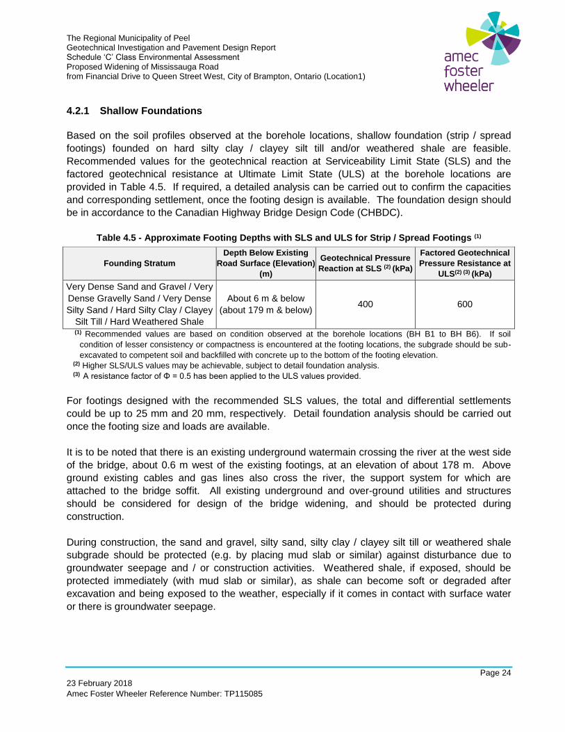
The Regional Municipality of Peel Geotechnical Investigation and Pavement Design Report Schedule ‘C’ Class Environmental Assessment Proposed Widening of Mississauga Road from Financial Drive to Queen Street West, City of Brampton, Ontario (Location1)
Page 24
23 February 2018
Amec Foster Wheeler Reference Number: TP115085
4.2.1 Shallow Foundations
Based on the soil profiles observed at the borehole locations, shallow foundation (strip / spread
footings) founded on hard silty clay / clayey silt till and/or weathered shale are feasible.
Recommended values for the geotechnical reaction at Serviceability Limit State (SLS) and the
factored geotechnical resistance at Ultimate Limit State (ULS) at the borehole locations are
provided in Table 4.5. If required, a detailed analysis can be carried out to confirm the capacities
and corresponding settlement, once the footing design is available. The foundation design should
be in accordance to the Canadian Highway Bridge Design Code (CHBDC).
Table 4.5 - Approximate Footing Depths with SLS and ULS for Strip / Spread Footings (1)
Founding Stratum
Depth Below Existing
Road Surface (Elevation)
(m)
Geotechnical Pressure
Reaction at SLS (2) (kPa)
Factored Geotechnical
Pressure Resistance at
ULS(2) (3) (kPa)
Very Dense Sand and Gravel / Very
Dense Gravelly Sand / Very Dense
Silty Sand / Hard Silty Clay / Clayey
Silt Till / Hard Weathered Shale
About 6 m & below
(about 179 m & below) 400 600
(1) Recommended values are based on condition observed at the borehole locations (BH B1 to BH B6). If soil
condition of lesser consistency or compactness is encountered at the footing locations, the subgrade should be sub-
excavated to competent soil and backfilled with concrete up to the bottom of the footing elevation. (2) Higher SLS/ULS values may be achievable, subject to detail foundation analysis. (3) A resistance factor of Φ = 0.5 has been applied to the ULS values provided.
For footings designed with the recommended SLS values, the total and differential settlements
could be up to 25 mm and 20 mm, respectively. Detail foundation analysis should be carried out
once the footing size and loads are available.
It is to be noted that there is an existing underground watermain crossing the river at the west side
of the bridge, about 0.6 m west of the existing footings, at an elevation of about 178 m. Above
ground existing cables and gas lines also cross the river, the support system for which are
attached to the bridge soffit. All existing underground and over-ground utilities and structures
should be considered for design of the bridge widening, and should be protected during
construction.
During construction, the sand and gravel, silty sand, silty clay / clayey silt till or weathered shale
subgrade should be protected (e.g. by placing mud slab or similar) against disturbance due to
groundwater seepage and / or construction activities. Weathered shale, if exposed, should be
protected immediately (with mud slab or similar), as shale can become soft or degraded after
excavation and being exposed to the weather, especially if it comes in contact with surface water
or there is groundwater seepage.
The Regional Municipality of Peel Geotechnical Investigation and Pavement Design Report Schedule ‘C’ Class Environmental Assessment Proposed Widening of Mississauga Road from Financial Drive to Queen Street West, City of Brampton, Ontario (Location1)
Page 25
23 February 2018
Amec Foster Wheeler Reference Number: TP115085
The design frost penetration for the City of Brampton is 1.2 m. Therefore, a permanent soil cover
of at least 1.2 m or its equivalent synthetic thermal insulation is required for frost protection of
foundations.
The excavations and dewatering consideration for the construction of bridge foundations are
discussed in Section 4.2.5. General consideration for excavation and dewatering discussed in
Section 11.3 should also be followed, as applicable.
4.2.2 Deep Foundations
Deep foundation, using driven piles or augered cast-in-place caissons, is a feasible option for
abutments and piers (if accessible by a pile driving rig). Driving piles through the hard / dense to
very dense soil is likely to be difficult. The deep foundation should be designed in accordance with
the latest Canadian Foundation Engineering Manual.
4.2.2.1 Driven Piles
Driven steel piles (i.e., HP 310 x 110) may be considered with the following axial geotechnical
forces:
Factored Axial Resistance at Ultimate Limit States = 900 kN
(including resistance factor = 0.4)
Based on the soil observed at the borehole locations, weathered shale was encountered at depths
varying from 7.2 m to 13.0 m (Elevation 177.7 m to 172.7 m) below existing road level. The piles
should be driven into the weathered shale. The factored ULS for pile shown above is conservative
for pile tips within weathered shale in order to prevent pile damage. Piles should be embedded at
least 1 m into the weathered shale. Minimum pile length should be specified by a structural
engineer. The actual pile length will depend on the weathered shale conditions, the minimum pile
length required and the pile driving criteria to achieve the pile capacity specified.
Accordingly, piles should be founded within weathered shale. Depths of weathered shale
encountered in the boreholes are listed in Table 4.6, and in Record of Boreholes. Soil profile along
the bridge is shown in Figure No. 2.
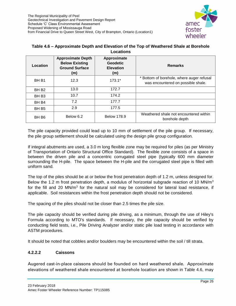
The Regional Municipality of Peel Geotechnical Investigation and Pavement Design Report Schedule ‘C’ Class Environmental Assessment Proposed Widening of Mississauga Road from Financial Drive to Queen Street West, City of Brampton, Ontario (Location1)
Page 26
23 February 2018
Amec Foster Wheeler Reference Number: TP115085
Table 4.6 – Approximate Depth and Elevation of the Top of Weathered Shale at Borehole
Locations
Location
Approximate Depth
Below Existing
Ground Surface
(m)
Approximate
Geodetic
Elevation
(m)
Remarks
BH B1 12.3 173.1* * Bottom of borehole, where auger refusal
was encountered on possible shale.
BH B2 13.0 172.7
BH B3 10.7 174.2
BH B4 7.2 177.7
BH B5 2.9 177.5
BH B6 Below 6.2 Below 178.9 Weathered shale not encountered within
borehole depth
The pile capacity provided could lead up to 10 mm of settlement of the pile group. If necessary,
the pile group settlement should be calculated using the design pile group configuration.
If integral abutments are used, a 3.0 m long flexible zone may be required for piles (as per Ministry of Transportation of Ontario Structural Office Standard). The flexible zone consists of a space in between the driven pile and a concentric corrugated steel pipe (typically 600 mm diameter surrounding the H-pile. The space between the H-pile and the corrugated steel pipe is filled with uniform sand.
The top of the piles should be at or below the frost penetration depth of 1.2 m, unless designed for.
Below the 1.2 m frost penetration depth, a modulus of horizontal subgrade reaction of 10 MN/m3
for the fill and 20 MN/m3 for the natural soil may be considered for lateral load resistance, if
applicable. Soil resistances within the frost penetration depth should not be considered.
The spacing of the piles should not be closer than 2.5 times the pile size.
The pile capacity should be verified during pile driving, as a minimum, through the use of Hiley's
Formula according to MTO's standards. If necessary, the pile capacity should be verified by
conducting field tests, i.e., Pile Driving Analyzer and/or static pile load testing in accordance with
ASTM procedures.
It should be noted that cobbles and/or boulders may be encountered within the soil / till strata.
4.2.2.2 Caissons
Augered cast-in-place caissons should be founded on hard weathered shale. Approximate
elevations of weathered shale encountered at borehole location are shown in Table 4.6, may
The Regional Municipality of Peel Geotechnical Investigation and Pavement Design Report Schedule ‘C’ Class Environmental Assessment Proposed Widening of Mississauga Road from Financial Drive to Queen Street West, City of Brampton, Ontario (Location1)
Page 27
23 February 2018
Amec Foster Wheeler Reference Number: TP115085
be used if driven piles are not applicable. Approximate elevations of the weathered shale is
also shown in the Figure No. 2 (soil profile along Huttonville Bridge). End bearing SLS value
of 900 kPa and factored ULS value of 1100 kPa may be used for preliminary design. For the SLS
value provided, the caissons could undergo a total settlement of up to 25 mm. The capacity of the
caisson will depend of its depth and size, side friction and end bearing. For conservative design,
side-resistances from the fill soils and the soils within the frost penetration depth should not be
considered.
Minimum caisson depth should be specified by a structural engineer. Caissons should be
embedded at least 1 m into the weathered shale.
The spacing of the caissons should not be closer than 2.5 times the caisson size. The top of
caissons should be at or below the frost penetration depth of 1.2 m, unless designed for. Modulus
of horizontal subgrade reactions provided in Section 4.2.2.1 may be considered for design of
caissons. Other design parameters provided in Section 4.2.3 may be used, as applicable.
Steel liners and/or dewatering may be required during caisson construction. After inserting
reinforcing steel cage in the caisson hole, concrete should be placed by tremie method, while
pulling the steel liner out without necking.
Excavation and dewatering for the construction of the footings are discussed in Section 4.2.5.
4.2.3 Soil Parameters for Design
Soil parameters for design are provided in Table 9.1 (Section 9.0).
4.2.4 Approach Embankment
The maximum height of existing approach embankments to the bridge was about 5 m, at the
southeast area of the bridge. As per the proposed plan, the road grade at the bridge is planned to
be increased by about 2 m. However, as the planned bridge will be longer than the existing
bridge, new abutments and piers will be located further away from the existing footings toward the
shore. The maximum height of embankment at the new abutments may be similar to or slightly
higher (about 6 m at the southeast area) than the existing embankment due to the grade raise. A
retaining wall (Retaining Wall No. 3) is planned for the southeast area of the bridge, as discussed
in Section 7.0 and as shown in Figure No. 1. For the rest of the approach areas, the soil condition,
recommendation and discussions provided in Section 3.0 (Road Widening) should be considered.
The new embankment slopes should be constructed at a slope of 2H:1V or flatter. For high
embankments (heights greater than 4.5 m), slope stability analysis should be carried during final
design.
The Regional Municipality of Peel Geotechnical Investigation and Pavement Design Report Schedule ‘C’ Class Environmental Assessment Proposed Widening of Mississauga Road from Financial Drive to Queen Street West, City of Brampton, Ontario (Location1)
Page 28
23 February 2018
Amec Foster Wheeler Reference Number: TP115085
For backfilling behind the abutments / retaining walls, OPSD 3101.150 (Walls, Abutment, Backfill,
Minimum Granular Requirement) should be considered.
4.2.5 Excavation and Dewatering for Bridge Foundation
The construction of new footings may require excavations to depths of about 2 m below the bottom
of the river for piers or up to 6 m below existing ground surface for abutments. River water will
have to be diverted around the excavation of pier footings in order to reduce water seepage into
the excavation.
For the construction of the pier, river dykes (or similar) will likely be required around the
construction zone.
Dewatering within the excavation will be required in order to keep the excavation dry during
construction. Dewatering requirements discussed in the hydrogeological report (submitted in a
separate cover) should be considered for dewatering plans. The control of water during
construction and the control of the water prior to discharge of water from dewatering operations to
the natural environment should be according to OPSS 517 (Dewatering of Pipeline, Utility and
Associated Structure Excavation) and OPSS 518 (Construction Specification for Control of Water
from Dewatering Operations). Environmental protection for construction in and around
waterbodies and on waterbody banks should follow OPSS.PROV 182 (General Specification for
Environmental Protection for Construction in Waterbodies and on Waterbody Banks). Temporary
erosion and sediment control measures, including to control the discharge of water, should be
according to OPSS 805 (Construction Specification for Temporary Erosion and Sediment Control
Measures).
General recommendations on excavation and dewatering, provided in Section 11.3, should also be
considered for design and construction.
4.2.6 Scour Protection
The bridge footings will require protection against scour and erosion, especially at the piers. Scour
protection may be provided by rip-rap, gabions, granular soil, or equivalent to protect the
foundations. Scour protection should be designed by an experienced Engineer according to OPSS
805 (Temporary Erosion and Sediment Control Measures).
If rip-rap protection is used, it should be separated from the natural soils with a geotextile filter
fabric (e.g., Terrafix 270R or better or similar) in accordance with OPSS 1860 (Geotextiles) or a
filter zone of granular material. The geotextile filter fabric should be selected based on size / type
of protection used and manufacturer’s recommended geotextile..
The Regional Municipality of Peel Geotechnical Investigation and Pavement Design Report Schedule ‘C’ Class Environmental Assessment Proposed Widening of Mississauga Road from Financial Drive to Queen Street West, City of Brampton, Ontario (Location1)
Page 29
23 February 2018
Amec Foster Wheeler Reference Number: TP115085
4.2.7 Earthquake Considerations
Based on the soil types encountered in the boreholes for bridge foundation (very dense sand and
gravel, hard silty clay / clayey silt till and hard weathered shale) and in conformance with Section
4.4.3.2 of the Canadian Highway Bridge Design Code (CHBDC, CAN/CSA-S6-14), the project site
conditions may be classified as “Site Class C” (very dense soil and soft rock). Site Coefficient
should be considered as per Table 4.2 to 4.9, Section 4.4.3.3 of CHBDC.
5.0 RETAINING WALL NO. 1
The planned Retaining Wall No. 1 will be located on the east side of Mississauga Road,
approximately between Station 10+990 to 11+090 (about 100 m long), as shown in Figure No. 1.
At this location, the retaining wall will be in a cut area. The maximum height of the existing slope
at the planned Retaining Wall No. 1 is about 4 m.
Two boreholes (BH R1 and BH R2) were drilled from the top of the existing slope along the plan
wall location. Based on the conditions at the borehole locations, the soil profile generally consisted
of surficial topsoil underlain by fill soils up to a depth of about 2.1 m, overlying loose to compact
natural silty sand / sand / silt. The retaining wall should be founded on the compact silty sand /
sand / silt (natural soils), which would be the encountered at the location, based on soil condition
at the borehole location. Loose sand was observed in BH R2 at a depth of about 7.6 m below
existing ground surface. The observed low SPT “N” value, which could possibly be due to
loosening of the sand below groundwater, may not represent the actual condition. However, any
soft or loose soil encountered at the founding level should be sub-excavated down to competent
soil and replaced with engineered fill. Based on the groundwater encountered at the borehole
locations, dewatering should be minimal of construction of the retaining wall. Surface water and /
or seepage from cut slope (perched water) should be considered for dewatering requirements.
Gravity type wall, reinforced-concrete cantilever wall (with the leg toward the road) or pile wall
without anchor (due to limited ROW) would be feasible types of wall, depending on height of wall.
For construction of the retaining wall, a temporary slope of 1H:1V or flatter will be required along
the wall alignment. If the available right-of-way does not allow for a slope temporary excavation,
temporary shoring system (e.g. trench box, soldier piles with lagging and rakers or similar) will be
required.
5.1 Sub-surface Conditions
The two boreholes (BH R1 and BH R2) were drilled to depths of 8.1 m below ground surface. The
boreholes were located in the vicinity of existing top of slope. Groundwater was encountered at
about 6.1 m below existing ground surface on completion of drilling at each borehole locations.
The Regional Municipality of Peel Geotechnical Investigation and Pavement Design Report Schedule ‘C’ Class Environmental Assessment Proposed Widening of Mississauga Road from Financial Drive to Queen Street West, City of Brampton, Ontario (Location1)
Page 30
23 February 2018
Amec Foster Wheeler Reference Number: TP115085
The stratigraphic units and groundwater conditions in BH R1 and BH R2 are presented in the
Record of Boreholes (Geotechnical Investigation). The laboratory test results are presented in
Appendix B. The following summary is to assist the designers of the project with an understanding
of the soil conditions encountered at the proposed retaining wall location. The soil and
groundwater conditions might vary between and beyond the borehole locations.
5.1.1 Surficial Cover – Topsoil
At each borehole location (BH R1 and BH R2), 150 mm thick topsoil was encountered at the
ground surface.
5.1.2 Fill Soils
Fill soils were encountered below the topsoil and consisted of silty sand fill, which extended to
depths of about 2.1 m and 1.4 m below the existing ground surface in Boreholes BH R1 and
BH R2, respectively.
The silty sand fill was brown and/or reddish brown in colour, and contained trace clay and gravel,
with rootlets and organic matter. SPT ‘N’ values measured within the silty sand fill ranged from 2
to 5 blows per 0.3 m. Water contents measured in the silty sand fill samples ranged from 6 % to
14 %.
5.1.3 Silty Sand / Sand
Natural silty sand / sand was encountered in each borehole underlying the silty sand fill, and
extended to the termination depth of 8.1 m in Borehole BH R1 and 7.1 m below ground surface in
Borehole BH R2.
The silty sand / sand was brown and/or light brown in colour, and contained trace clay and silt,
trace gravel. SPT ‘N’ values measured in silty sand /sand varied from 6 to 18 blows per 0.3 m,
implying a loose to compact state of compactness. Water contents measured in the silty sand /
sand ranged from 2 % to 25 %.
A grain size analysis was completed on one selected sample of sand from Borehole BH R1. The
results are presented in Table 5.1 and shown in the Record of Boreholes.
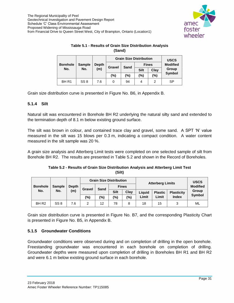
The Regional Municipality of Peel Geotechnical Investigation and Pavement Design Report Schedule ‘C’ Class Environmental Assessment Proposed Widening of Mississauga Road from Financial Drive to Queen Street West, City of Brampton, Ontario (Location1)
Page 31
23 February 2018
Amec Foster Wheeler Reference Number: TP115085
Table 5.1 - Results of Grain Size Distribution Analysis
(Sand)
Borehole
No.
Sample
No.
Depth
(m)
Grain Size Distribution USCS
Modified
Group
Symbol
Gravel Sand Fines
Silt Clay
(%) (%) (%) (%)
BH R1 SS 8 7.6 0 94 4 2 SP
Grain size distribution curve is presented in Figure No. B6, in Appendix B.
5.1.4 Silt
Natural silt was encountered in Borehole BH R2 underlying the natural silty sand and extended to
the termination depth of 8.1 m below existing ground surface.
The silt was brown in colour, and contained trace clay and gravel, some sand. A SPT ‘N’ value
measured in the silt was 15 blows per 0.3 m, indicating a compact condition. A water content
measured in the silt sample was 20 %.
A grain size analysis and Atterberg Limit tests were completed on one selected sample of silt from
Borehole BH R2. The results are presented in Table 5.2 and shown in the Record of Boreholes.
Table 5.2 - Results of Grain Size Distribution Analysis and Atterberg Limit Test
(Silt)
Borehole
No.
Sample
No.
Depth
(m)
Grain Size Distribution Atterberg Limits USCS
Modified
Group
Symbol
Gravel Sand Fines
Silt Clay Liquid
Limit
Plastic
Limit
Plasticity
Index (%) (%) (%) (%)
BH R2 SS 8 7.6 2 12 78 8 18 15 3 ML
Grain size distribution curve is presented in Figure No. B7, and the corresponding Plasticity Chart
is presented in Figure No. B5, in Appendix B.
5.1.5 Groundwater Conditions
Groundwater conditions were observed during and on completion of drilling in the open borehole.
Freestanding groundwater was encountered in each borehole on completion of drilling.
Groundwater depths were measured upon completion of drilling in Boreholes BH R1 and BH R2
and were 6.1 m below existing ground surface in each borehole.
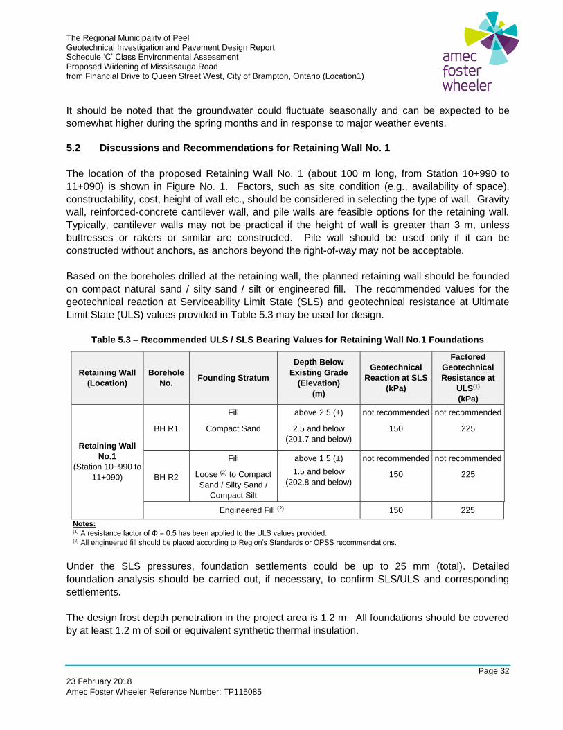
The Regional Municipality of Peel Geotechnical Investigation and Pavement Design Report Schedule ‘C’ Class Environmental Assessment Proposed Widening of Mississauga Road from Financial Drive to Queen Street West, City of Brampton, Ontario (Location1)
Page 32
23 February 2018
Amec Foster Wheeler Reference Number: TP115085
It should be noted that the groundwater could fluctuate seasonally and can be expected to be
somewhat higher during the spring months and in response to major weather events.
5.2 Discussions and Recommendations for Retaining Wall No. 1
The location of the proposed Retaining Wall No. 1 (about 100 m long, from Station 10+990 to
11+090) is shown in Figure No. 1. Factors, such as site condition (e.g., availability of space),
constructability, cost, height of wall etc., should be considered in selecting the type of wall. Gravity
wall, reinforced-concrete cantilever wall, and pile walls are feasible options for the retaining wall.
Typically, cantilever walls may not be practical if the height of wall is greater than 3 m, unless
buttresses or rakers or similar are constructed. Pile wall should be used only if it can be
constructed without anchors, as anchors beyond the right-of-way may not be acceptable.
Based on the boreholes drilled at the retaining wall, the planned retaining wall should be founded
on compact natural sand / silty sand / silt or engineered fill. The recommended values for the
geotechnical reaction at Serviceability Limit State (SLS) and geotechnical resistance at Ultimate
Limit State (ULS) values provided in Table 5.3 may be used for design.
Table 5.3 – Recommended ULS / SLS Bearing Values for Retaining Wall No.1 Foundations
Retaining Wall
(Location)
Borehole
No. Founding Stratum
Depth Below
Existing Grade
(Elevation)
(m)
Geotechnical
Reaction at SLS
(kPa)
Factored
Geotechnical
Resistance at
ULS(1)
(kPa)
Retaining Wall
No.1
(Station 10+990 to
11+090)
BH R1
Fill
Compact Sand
above 2.5 (±)
2.5 and below
(201.7 and below)
not recommended
150
not recommended
225
BH R2
Fill
Loose (2) to Compact
Sand / Silty Sand /
Compact Silt
above 1.5 (±)
1.5 and below
(202.8 and below)
not recommended
150
not recommended
225
Engineered Fill (2) 150 225
Notes: (1) A resistance factor of Φ = 0.5 has been applied to the ULS values provided. (2) All engineered fill should be placed according to Region’s Standards or OPSS recommendations.
Under the SLS pressures, foundation settlements could be up to 25 mm (total). Detailed
foundation analysis should be carried out, if necessary, to confirm SLS/ULS and corresponding
settlements.
The design frost depth penetration in the project area is 1.2 m. All foundations should be covered
by at least 1.2 m of soil or equivalent synthetic thermal insulation.
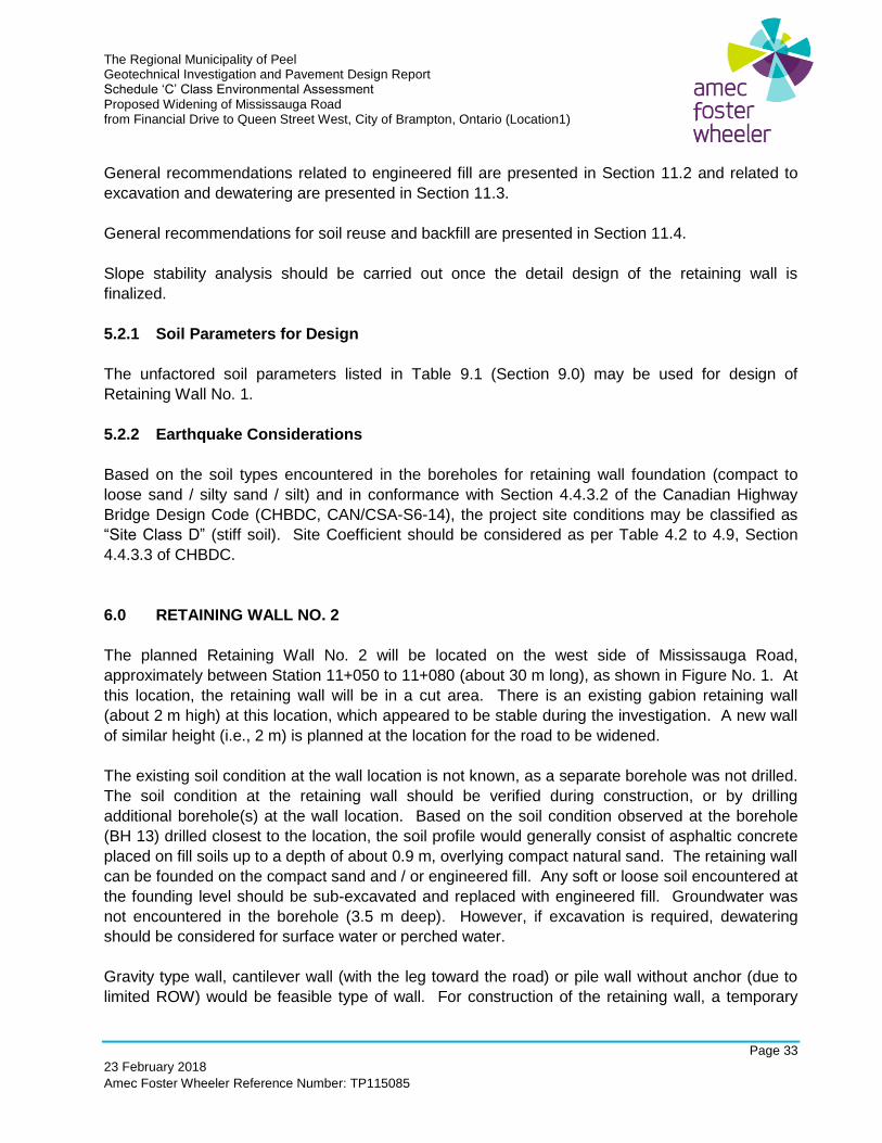
The Regional Municipality of Peel Geotechnical Investigation and Pavement Design Report Schedule ‘C’ Class Environmental Assessment Proposed Widening of Mississauga Road from Financial Drive to Queen Street West, City of Brampton, Ontario (Location1)
Page 33
23 February 2018
Amec Foster Wheeler Reference Number: TP115085
General recommendations related to engineered fill are presented in Section 11.2 and related to
excavation and dewatering are presented in Section 11.3.
General recommendations for soil reuse and backfill are presented in Section 11.4.
Slope stability analysis should be carried out once the detail design of the retaining wall is
finalized.
5.2.1 Soil Parameters for Design
The unfactored soil parameters listed in Table 9.1 (Section 9.0) may be used for design of
Retaining Wall No. 1.
5.2.2 Earthquake Considerations
Based on the soil types encountered in the boreholes for retaining wall foundation (compact to
loose sand / silty sand / silt) and in conformance with Section 4.4.3.2 of the Canadian Highway
Bridge Design Code (CHBDC, CAN/CSA-S6-14), the project site conditions may be classified as
“Site Class D” (stiff soil). Site Coefficient should be considered as per Table 4.2 to 4.9, Section
4.4.3.3 of CHBDC.
6.0 RETAINING WALL NO. 2
The planned Retaining Wall No. 2 will be located on the west side of Mississauga Road,
approximately between Station 11+050 to 11+080 (about 30 m long), as shown in Figure No. 1. At
this location, the retaining wall will be in a cut area. There is an existing gabion retaining wall
(about 2 m high) at this location, which appeared to be stable during the investigation. A new wall
of similar height (i.e., 2 m) is planned at the location for the road to be widened.
The existing soil condition at the wall location is not known, as a separate borehole was not drilled.
The soil condition at the retaining wall should be verified during construction, or by drilling
additional borehole(s) at the wall location. Based on the soil condition observed at the borehole
(BH 13) drilled closest to the location, the soil profile would generally consist of asphaltic concrete
placed on fill soils up to a depth of about 0.9 m, overlying compact natural sand. The retaining wall
can be founded on the compact sand and / or engineered fill. Any soft or loose soil encountered at
the founding level should be sub-excavated and replaced with engineered fill. Groundwater was
not encountered in the borehole (3.5 m deep). However, if excavation is required, dewatering
should be considered for surface water or perched water.
Gravity type wall, cantilever wall (with the leg toward the road) or pile wall without anchor (due to
limited ROW) would be feasible type of wall. For construction of the retaining wall, a temporary
The Regional Municipality of Peel Geotechnical Investigation and Pavement Design Report Schedule ‘C’ Class Environmental Assessment Proposed Widening of Mississauga Road from Financial Drive to Queen Street West, City of Brampton, Ontario (Location1)
Page 34
23 February 2018
Amec Foster Wheeler Reference Number: TP115085
slope of 1H:1V or flatter will be required along the wall alignment. If this is not possible, temporary
shoring system (e.g. trench boxes or similar) may be required.
6.1 Sub-surface Conditions
The borehole closest to the planned location of Retaining Wall No. 2 was Borehole BH 13 (about
20 m east at the west side of Mississauga Road). The stratigraphic units and groundwater
conditions observed in BH 13 are presented in the Record of Boreholes (Geotechnical
Investigation). The soil condition at the wall should be verified by a geotechnical engineer during
construction, or by drilling additional borehole(s) at the wall location.
6.2 Discussions and Recommendations for Retaining Wall No. 2
The location of the proposed Retaining Wall No. 2 (about 30 m long, from Station 11+050 to
11+080) is shown in Figure No. 1. Based on the borehole BH 13, the proposed retaining wall
should be founded on competent sand or engineered fill. Gravity wall, cantilever wall with leg
toward the road, pile wall (without anchor) are feasible options for the retaining wall types. For the
planned wall, a gabion wall, similar to the existing one, should be considered.
For soil similar to the one observed at Borehole BH 13, i.e., compact sand, a geotechnical reaction
at Serviceability Limit State (SLS) of 150 kPa and a geotechnical resistance at Ultimate Limit State
(ULS) of 225 kPa may be used for design.
To achieve the recommended bearing capacity, the retaining wall should be founded on compact
sand. The exposed subgrade should be proof-rolled to verify soil condition. If soft or loose soils
should be should be sub-excavated and backfilled with engineered fill. Under the SLS pressures,
foundation settlements could be up to 25 mm.
The unfactored soil parameters listed in Table 9.1 (Section 9.0) may be used for design of
Retaining Wall No. 2. Recommendations / discussions provided in Section 5.0 should also be
considered for design of Retaining Wall No. 2, as applicable.
Earthquake consideration discussed in Section 5.2.2 may be used for design consideration.
7.0 RETAINING WALL NO. 3
Retaining Wall No. 3 (about 90 m long, approximate Station 10+380 to 10+470) is planned at the
southeast side of the bridge over Credit River, as shown in Figure No. 1. The existing
embankment (at the existing abutment) is about 5 m high, with the Credit River close to the toe of
the slope. The road grade at the bridge is planned to be increased by about 2 m. The new
abutments would be located further away from the river than the existing abutment, as the new
The Regional Municipality of Peel Geotechnical Investigation and Pavement Design Report Schedule ‘C’ Class Environmental Assessment Proposed Widening of Mississauga Road from Financial Drive to Queen Street West, City of Brampton, Ontario (Location1)
Page 35
23 February 2018
Amec Foster Wheeler Reference Number: TP115085
bridge is longer than the existing bridge. The maximum height of slope at the location of Retaining
Wall No. 3 may be similar to or slightly higher (about 6 m) than the existing slope height.
Borehole BH B5 was drilled at the toe of the existing slope, as shown in Figure No. 1 to confirm the
soil condition observed in Borehole BH B4. Based on the soil conditions at the borehole locations
(BH B4 and B5), the soil profile generally consisted of surficial topsoil underlain by fill soils up to a
depth of about 1.8 m, overlying dense natural sand and gravel and hard silty clay / clayey silt till.
The retaining wall can be founded on the dense sand and gravel, and/or hard silty clay and/or
engineered fill. Any soft or loose soil encountered at the founding level should be sub-excavated
and replaced with engineered fill. Groundwater was not encountered in Borehole BH B5 during
the field investigation. However, in the monitoring well installed in BH B4, groundwater was
encountered at levels close the ground surface at BH B5. Therefore, if excavation is required for
construction of the wall, dewatering will likely be required, and may be carried out by using a sump
and pump system.
Gravity wall (including mechanically stabilized earth (MSE) wall) and pile walls (with anchors) are
feasible wall types. As there are existing underground utilities / structures (sewer / sewer outlet) in
the area, protection and/or relocation of the utilities / structures should be considered for design
and construction of the wall. Constructability and accessibility for construction should also be
considered in selecting the wall type.
7.1 Sub-surface Conditions
Boreholes BH B4 and BH B5 provide the available soil conditions encountered at the planned
retaining wall location. The following summary is to assist the designers of the project. The
stratigraphic units and groundwater conditions observed in Boreholes BH B4 and BH B5 are
discussed in Section 4.1 and presented in the Record of Boreholes. The laboratory test results are
presented in Appendix B. It should be noted that the soil and groundwater conditions might vary
beyond the borehole location.
At the borehole locations, the soil profile generally consisted of surficial cover (topsoil / asphaltic
concrete) overlying fills soil, which was underlain natural soils and / or weathered shale.
At Borehole BH B4 location (ground elevation 184.9 m), which was drilled at the existing road
surface, the soil profile consisted of 300 mm thick asphaltic concrete, underlain by fill soils (sand
and gravel / gravelly sand / silty sand / sand / sandy gravel fill), which extended to a depth of about
5.6 m below the existing ground surface. The fill soil was underlain by hard silty clay / clayey silt
till, which extended to a depth of about 7.2 m below existing ground surface. Weathered shale
was encountered below the silty clay / clayey silt till to the termination depth of the borehole at 11.6
m below ground surface. The borehole was terminated due to auger refusal (possible bedrock).
At Borehole BH B5 location (ground elevation 180.5 m), the soil profile consisted of 120 mm thick
topsoil, underlain by fill soil consisting of silty sand fill, which extended to a depth of about 1.8 m

The Regional Municipality of Peel Geotechnical Investigation and Pavement Design Report Schedule ‘C’ Class Environmental Assessment Proposed Widening of Mississauga Road from Financial Drive to Queen Street West, City of Brampton, Ontario (Location1)
Page 36
23 February 2018
Amec Foster Wheeler Reference Number: TP115085
below the existing ground surface. The fill soil was underlain by dense natural sand and gravel,
and extended to about 2.9 m below ground surface. Hard silty clay / clayey silt till was
encountered below the sand and gravel, and extended to the termination depth of the borehole at
3.0 m below existing ground surface. The borehole was terminated due to (hand) auger refusal
(possible bedrock/weathered shale).
No freestanding groundwater was not observed in the open borehole on completion of drilling.
However, groundwater was measured at a depth about 4.7 m (Elevation 180.2 m) below ground
surface in the monitoring well installed in Borehole BH 4.
It should be noted that the groundwater could fluctuate seasonally or with river water level and can
be expected to be somewhat higher during the spring months and in response to major weather
events.
7.2 Discussions and Recommendations for Retaining Wall No. 3
The location of the planned Retaining Wall No. 3 (about 90 m long, from Station 10+380 to
10+470) is shown in Figure No. 1. Based on the boreholes drilled in the vicinity, the retaining wall
can be founded on the dense sand and gravel, hard silty clay / clayey silt till, weathered shale or
engineered fill. Gravity wall (including MSE) and pile wall with anchor are feasible. The retaining
wall will be located between the road and Credit River, and close to the river. Also, based on
sewer outlets observed at the bottom of the slope, there are existing sewers under the road.
Constructability of the wall should be considered in selecting the wall type. Temporary retaining
structure may be required along the existing road to prepare access to the wall site.
The recommended values for the geotechnical reaction at Serviceability Limit State (SLS) and
geotechnical resistance at Ultimate Limit State (ULS) values provided in Table 7.1 may be used for
design.

The Regional Municipality of Peel Geotechnical Investigation and Pavement Design Report Schedule ‘C’ Class Environmental Assessment Proposed Widening of Mississauga Road from Financial Drive to Queen Street West, City of Brampton, Ontario (Location1)
Page 37
23 February 2018
Amec Foster Wheeler Reference Number: TP115085
Table 7.1 – Recommended ULS / SLS Bearing Values for Retaining Wall Foundations
Retaining Wall
(Location)
Borehole
No. Founding Stratum
Depth Below
Existing Grade
(m)
Geotechnical
Reaction at SLS
(kPa) (1)
Factored
Geotechnical
Resistance at
ULS (1) (2)
(kPa)
Retaining Wall
No. 3
(Station 10+380 to
10+470)
BH B4
Fill
Hard Silty Clay / Clayey Silt Till /
Hard weathered shale
Above 5.6 (±) (179.3 and above)
5.6 to 7.2 (±)
(178.8 to177.7)
7.2 and below (177.7 and below)
Not recommended
300
400
Not recommended
450
600
BH B5
Fill
Dense Sand and
Gravel
Hard Silty Clay /
Clayey Silt Till
above 1.8 (±)
1.8 to 2.9 (±)
(178.5 to 177.5)
2.9 and below
(177.5 and below)
not recommended
200
300
not recommended
300
450
Engineered Fill(3) 150 to 200(4) 225 to 300(4)
Notes: (1) Footing should not be placed on the slope. (2) A resistance factor of Φ = 0.5 has been applied to the ULS values provided. (3) All engineered fill should be placed according to Region’s Standards or OPSS recommendations. (4) Depending on the subgrade conditions and soil types used.
Under the SLS pressures, foundation settlements could be up to 25 mm. Detail foundation
analysis should be carried out, if necessary, to confirm SLS/ULS and corresponding settlements.
The unfactored soil parameters provided in Section 9.0 may be used for design of the proposed
Retaining Wall No. 3.
Earthquake consideration discussed in Section 4.2.7 may be used for design consideration.
The design frost depth penetration in the project area is 1.2 m. All foundations should be covered
by at least 1.2 m of soil or equivalent synthetic thermal insulation.
General recommendations related to engineered fill are presented in Section 11.2 and related to
excavation and dewatering are presented in Section 11.3.
General recommendations for soil reuse and backfill are presented in Section 11.4.
Slope stability analysis should be carried out once the detail design of the retaining wall is
finalized.
The Regional Municipality of Peel Geotechnical Investigation and Pavement Design Report Schedule ‘C’ Class Environmental Assessment Proposed Widening of Mississauga Road from Financial Drive to Queen Street West, City of Brampton, Ontario (Location1)
Page 38
23 February 2018
Amec Foster Wheeler Reference Number: TP115085
8.0 UNDERGROUND UTILITES
As per the information provided, new storm sewer and / or relocation of existing storm sewer is
planned along the road. There is an existing watermain which crosses Credit River, just east of
the bridge. No sewer and / or watermain is planned across Credit River. The existing underground
utilities should be protected and taken into consideration for design and construction of the road
widening, bridge and retaining walls. Sub-surface conditions discussed for road widening (Section
3.1), bridge foundation (Section 4.1) and retaining walls (Sections 5.1, 6.1 and 7.1) should be
considered for design and construction of the underground utilities.
8.1 General Sub-Surface Conditions
Based on the investigation results, the subsurface soils consisted of fill soils to depths varying from
2.1 m to 5.6 m below the ground surface, which were underlain by natural deposits of sand and
gravel, sandy gravel, sand, silty sand / sandy silt, silty sand / sandy silt till, silty clay / clayey silt till
and/or weathered shale.
8.2 Subgrade for Underground Utilities
It is recommended that underground utilities (e.g., sewers, manholes, etc.) be founded on
competent soil (existing fill or natural soil) or engineered fill. The fill soils encountered in the
boreholes were generally firm to very stiff or very loose to very dense. The natural soils were
generally loose to very dense or hard. The underground utilities / manholes should be founded on
compact to very dense or firm to hard subgrade (for both fill and natural soils). If very soft / soft /
very loose / loose soils are encountered at the invert or founding level of underground utilities /
manholes, the existing subgrade soils should be re-compacted, if possible, or sub-excavate and
replace with compacted engineered fill.
Manholes (or similar structures) may be founded on compact to very dense or firm to hard
subgrade engineered fill.
The frost penetration depth for the project area should be considered as 1.2 m.
Based on groundwater levels encountered in the boreholes, substantial dewatering is not expected
during construction of the underground utilities. Where required, dewatering may be achieved
using sump and pump system and / or gravity drainage (or a combination thereof). Discussion
about excavation and dewatering included in Section 11.3 should also be considered.
8.3 Pipe Bedding
It is recommended that a minimum of 150 mm thick bedding material (Class ‘B’ Type or better) be
placed below the pipe invert. The thickness of the bedding may have to be increased depending
on the pipe diameter, or if wet or weak subgrade conditions are encountered. If the subgrade is

The Regional Municipality of Peel Geotechnical Investigation and Pavement Design Report Schedule ‘C’ Class Environmental Assessment Proposed Widening of Mississauga Road from Financial Drive to Queen Street West, City of Brampton, Ontario (Location1)
Page 39
23 February 2018
Amec Foster Wheeler Reference Number: TP115085
weak, it should be sub-excavated and replaced with engineered fill to support the pipes and allow
the use of Class 'B' Type bedding. Lean concrete (minimum 100 mm thick) may be used in lieu of
engineered fill to provide a workable surface and support the pipes. Construction of underground
pipes should be carried out in accordance with the relevant OPSS 410 (Construction Specification
for Pipe Sewer Installation in Open Cut), or other relevant applicable municipal / regional
standards.
Should the pipes be installed in soft clay soils, the joints should be restrained from movements and
the backfill around the pipes should be properly compacted in order to prevent long-term
movements. The possibility of underground pipe movements in soft clayey soils, during and after
installation, should be considered in the design and construction of the underground pipes.
Bedding for underground pipes should be placed in accordance to OPSD 802.10 for flexible pipes
and OPSD 802.30, 802.31 and 802.32 for rigid pipes.
9.0 SOIL PARAMETERS FOR DESIGN
The unfactored soil parameters listed in Table 9.1 may be used for design of structures.
It should be noted that the above design soil parameters assume level ground surface and backfill
behind the retaining structure, and are based on published information and/or semi-empirical /
theoretical relationships. The parameters provided are conservative and should be verified by
field / laboratory testing if more representative parameters are required.
The Regional Municipality of Peel Geotechnical Investigation and Pavement Design Report Schedule ‘C’ Class Environmental Assessment Proposed Widening of Mississauga Road from Financial Drive to Queen Street West, City of Brampton, Ontario (Location1)
Page 40
23 February 2018
Amec Foster Wheeler Reference Number: TP115085
Table 9.1 - Unfactored Static Soil Parameters for Design
Material
Total Stress
Analysis
Effective
Stress
Analysis
Earth Pressure
Coefficients (1)
Bulk
Unit
Weight
(kN/m3)
Coefficient
of Friction
between
Concrete
and Soil
C
(kPa)
Φ
(deg)
c’
(kPa)
Φ’
(deg)
Active
Ka
At-Rest
Ko
Passive
Kp
Very dense sand
and gravel 0 35 0 35 0.27 0.43 3.7 21 0.45
Hard silty clay /
clayey silt till /
weathered shale
100 0 0 30 0.33 0.50 3.0 20 0.40
Loose to
compact silty
sand / sand / silt
0 30 0 30(3) 0.33 0.50 3.0 19 0.35
Engineered Fill (2)
Granular A
(OPSS 1010) 0 35 0 35 0.27 0.43 3.7 24(3)
0.40 Granular A
(OPSS 1010) 0 35 0 35 0.27 0.43 3.7 24(3)
(1) Values based on semi-empirical relationships. For SLS, Kp values should be reduced to 1/3 of indicated value to limit lateral
movement. (2) All engineered fill should be compacted to at least 100 % SPMDD for supporting foundations. (3) Unit weight values for engineered fill compacted to 100 % SPMDD. For backfill of retaining wall, unit weights for Granular A and
Granular B compacted to 95 % SPMDD may be taken as 22 kN/m3 and 21 kN/m3, respectively.
10.0 PAVEMENT INVESTIGATION AND DESIGN
10.1 Pavement Evaluation
10.1.1 Visual Pavement Condition Survey
Amec Foster Wheeler completed a visual pavement condition survey of the existing road surface
within the project area to identify any distress. The identification and classification of the pavement
distresses were carried out in accordance with MTO’s “Flexible Pavement Condition Rating
Manual – Guidelines for Municipalities”, SP-022.
Generally, Mississauga Road (RR1) is a north-south Regional Arterial Road that extends from
Caledon in the north, through the City of Brampton, and to the City of Mississauga in the south.
The existing asphaltic concrete surface within the investigation limits of Mississauga Road from
380 m north of Financial Drive to Queen Street West ranged from ‘Good to Fairly Good Condition’.
Selected photographs showing the existing condition of the investigated road section are
presented in Appendix A.
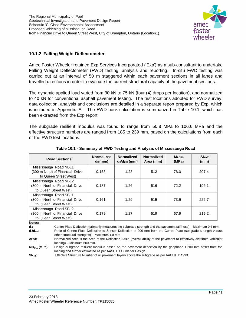
The Regional Municipality of Peel Geotechnical Investigation and Pavement Design Report Schedule ‘C’ Class Environmental Assessment Proposed Widening of Mississauga Road from Financial Drive to Queen Street West, City of Brampton, Ontario (Location1)
Page 41
23 February 2018
Amec Foster Wheeler Reference Number: TP115085
10.1.2 Falling Weight Deflectometer
Amec Foster Wheeler retained Exp Services Incorporated ('Exp') as a sub-consultant to undertake
Falling Weight Deflectometer (FWD) testing, analysis and reporting. In-situ FWD testing was
carried out at an interval of 50 m staggered within each pavement sections in all lanes and
travelled directions in order to evaluate the current structural capacity of the pavement sections.
The dynamic applied load varied from 30 kN to 75 kN (four (4) drops per location), and normalized
to 40 kN for conventional asphalt pavement testing. The test locations adopted for FWD survey,
data collection, analysis and conclusions are detailed in a separate report prepared by Exp, which
is included in Appendix ‘A’. The FWD back-calculation is summarized in Table 10.1, which has
been extracted from the Exp report.
The subgrade resilient modulus was found to range from 50.8 MPa to 106.6 MPa and the
effective structure numbers are ranged from 185 to 239 mm, based on the calculations from each
of the FWD test locations.
Table 10.1 - Summary of FWD Testing and Analysis of Mississauga Road
Road Sections Normalized
d0 (mm)
Normalized
d0/d200 (mm)
Normalized
Area (mm)
MRDES
(MPa)
SNeff
(mm)
Mississauga Road NBL1
(300 m North of Financial Drive
to Queen Street West)
0.158 1.28 512 78.0 207.4
Mississauga Road NBL2
(300 m North of Financial Drive
to Queen Street West)
0.187 1.26 516 72.2 196.1
Mississauga Road SBL1
(300 m North of Financial Drive
to Queen Street West)
0.161 1.29 515 73.5 222.7
Mississauga Road SBL2
(300 m North of Financial Drive
to Queen Street West)
0.179 1.27 519 67.9 215.2
Notes:
d0: Centre Plate Deflection (primarily measures the subgrade strength and the pavement stiffness) – Maximum 0.6 mm.
d0/d200: Ratio of Centre Plate Deflection to Sensor Deflection at 200 mm from the Centre Plate (subgrade strength versus
other structural strengths) – Maximum 1.8 mm
Area: Normalized Area is the Area of the Deflection Basin (overall ability of the pavement to effectively distribute vehicular
loading) – Minimum 600 mm.
MRDES (MPa): Design subgrade resilient modulus based on the pavement deflection by the geophone 1,200 mm offset from the
loading and further estimated as per AASHTO Guide for Design.
SNeff: Effective Structure Number of all pavement layers above the subgrade as per AASHTO’ 1993.
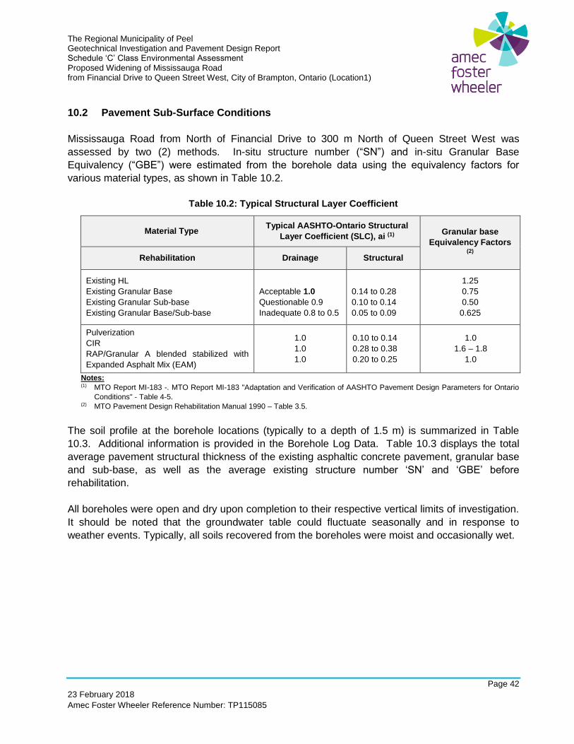
The Regional Municipality of Peel Geotechnical Investigation and Pavement Design Report Schedule ‘C’ Class Environmental Assessment Proposed Widening of Mississauga Road from Financial Drive to Queen Street West, City of Brampton, Ontario (Location1)
Page 42
23 February 2018
Amec Foster Wheeler Reference Number: TP115085
10.2 Pavement Sub-Surface Conditions
Mississauga Road from North of Financial Drive to 300 m North of Queen Street West was
assessed by two (2) methods. In-situ structure number (“SN”) and in-situ Granular Base
Equivalency (“GBE”) were estimated from the borehole data using the equivalency factors for
various material types, as shown in Table 10.2.
Table 10.2: Typical Structural Layer Coefficient
Material Type Typical AASHTO-Ontario Structural
Layer Coefficient (SLC), ai (1) Granular base
Equivalency Factors (2)
Rehabilitation Drainage Structural
Existing HL
Existing Granular Base
Existing Granular Sub-base
Existing Granular Base/Sub-base
Acceptable 1.0
Questionable 0.9
Inadequate 0.8 to 0.5
0.14 to 0.28
0.10 to 0.14
0.05 to 0.09
1.25
0.75
0.50
0.625
Pulverization
CIR
RAP/Granular A blended stabilized with
Expanded Asphalt Mix (EAM)
1.0
1.0
1.0
0.10 to 0.14
0.28 to 0.38
0.20 to 0.25
1.0
1.6 – 1.8
1.0
Notes: (1) MTO Report MI-183 -. MTO Report MI-183 "Adaptation and Verification of AASHTO Pavement Design Parameters for Ontario
Conditions" - Table 4-5. (2) MTO Pavement Design Rehabilitation Manual 1990 – Table 3.5.
The soil profile at the borehole locations (typically to a depth of 1.5 m) is summarized in Table
10.3. Additional information is provided in the Borehole Log Data. Table 10.3 displays the total
average pavement structural thickness of the existing asphaltic concrete pavement, granular base
and sub-base, as well as the average existing structure number ‘SN’ and ‘GBE’ before
rehabilitation.
All boreholes were open and dry upon completion to their respective vertical limits of investigation.
It should be noted that the groundwater table could fluctuate seasonally and in response to
weather events. Typically, all soils recovered from the boreholes were moist and occasionally wet.
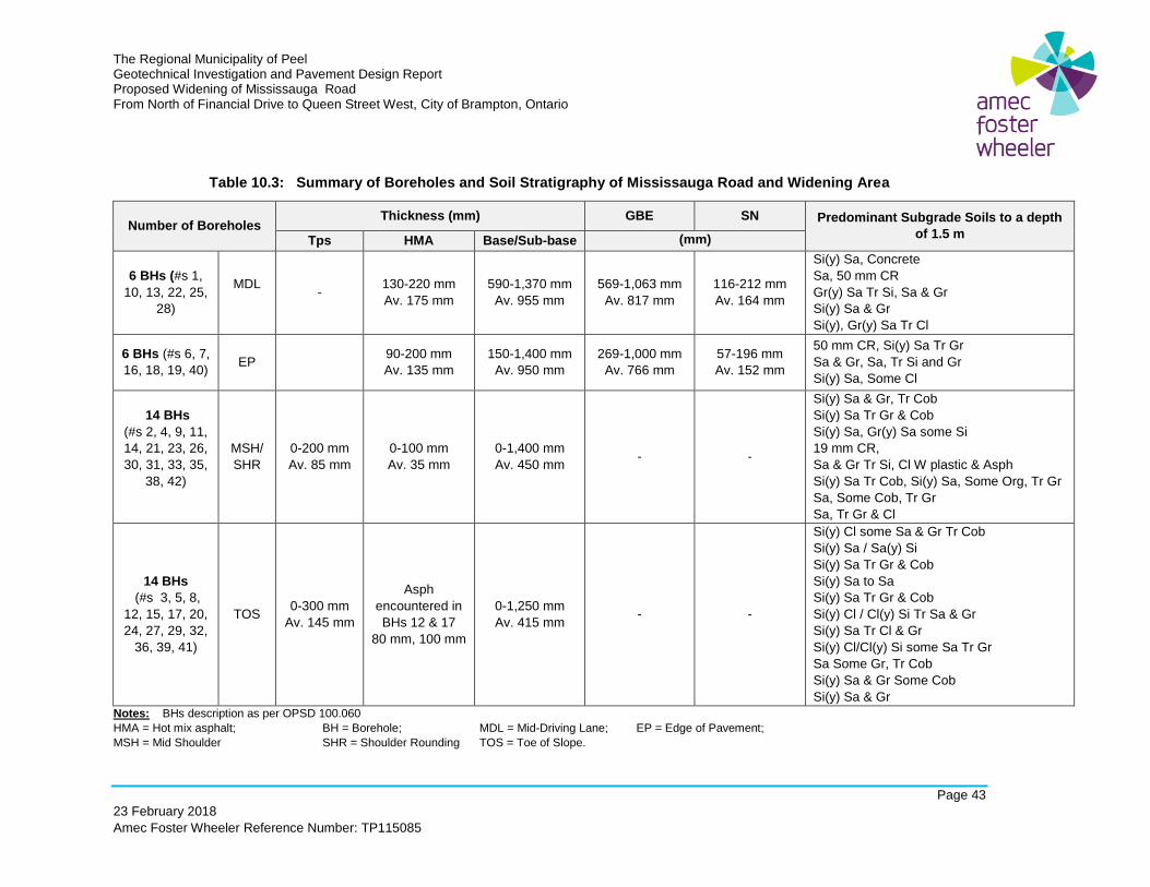
The Regional Municipality of Peel Geotechnical Investigation and Pavement Design Report Proposed Widening of Mississauga Road From North of Financial Drive to Queen Street West, City of Brampton, Ontario
Page 43
23 February 2018
Amec Foster Wheeler Reference Number: TP115085
Table 10.3: Summary of Boreholes and Soil Stratigraphy of Mississauga Road and Widening Area
Number of Boreholes Thickness (mm) GBE SN Predominant Subgrade Soils to a depth
of 1.5 m Tps HMA Base/Sub-base (mm)
6 BHs (#s 1,
10, 13, 22, 25,
28)
MDL
-
130-220 mm
Av. 175 mm
590-1,370 mm
Av. 955 mm
569-1,063 mm
Av. 817 mm
116-212 mm
Av. 164 mm
Si(y) Sa, Concrete
Sa, 50 mm CR
Gr(y) Sa Tr Si, Sa & Gr
Si(y) Sa & Gr
Si(y), Gr(y) Sa Tr Cl
6 BHs (#s 6, 7,
16, 18, 19, 40) EP
90-200 mm
Av. 135 mm
150-1,400 mm
Av. 950 mm
269-1,000 mm
Av. 766 mm
57-196 mm
Av. 152 mm
50 mm CR, Si(y) Sa Tr Gr
Sa & Gr, Sa, Tr Si and Gr
Si(y) Sa, Some Cl
14 BHs
(#s 2, 4, 9, 11,
14, 21, 23, 26,
30, 31, 33, 35,
38, 42)
MSH/
SHR
0-200 mm
Av. 85 mm
0-100 mm
Av. 35 mm
0-1,400 mm
Av. 450 mm - -
Si(y) Sa & Gr, Tr Cob
Si(y) Sa Tr Gr & Cob
Si(y) Sa, Gr(y) Sa some Si
19 mm CR,
Sa & Gr Tr Si, Cl W plastic & Asph
Si(y) Sa Tr Cob, Si(y) Sa, Some Org, Tr Gr
Sa, Some Cob, Tr Gr
Sa, Tr Gr & Cl
14 BHs
(#s 3, 5, 8,
12, 15, 17, 20,
24, 27, 29, 32,
36, 39, 41)
TOS 0-300 mm
Av. 145 mm
Asph
encountered in
BHs 12 & 17
80 mm, 100 mm
0-1,250 mm
Av. 415 mm - -
Si(y) Cl some Sa & Gr Tr Cob
Si(y) Sa / Sa(y) Si
Si(y) Sa Tr Gr & Cob
Si(y) Sa to Sa
Si(y) Sa Tr Gr & Cob
Si(y) Cl / Cl(y) Si Tr Sa & Gr
Si(y) Sa Tr Cl & Gr
Si(y) Cl/Cl(y) Si some Sa Tr Gr
Sa Some Gr, Tr Cob
Si(y) Sa & Gr Some Cob
Si(y) Sa & Gr
Notes: BHs description as per OPSD 100.060
HMA = Hot mix asphalt; BH = Borehole; MDL = Mid-Driving Lane; EP = Edge of Pavement;
MSH = Mid Shoulder SHR = Shoulder Rounding TOS = Toe of Slope.
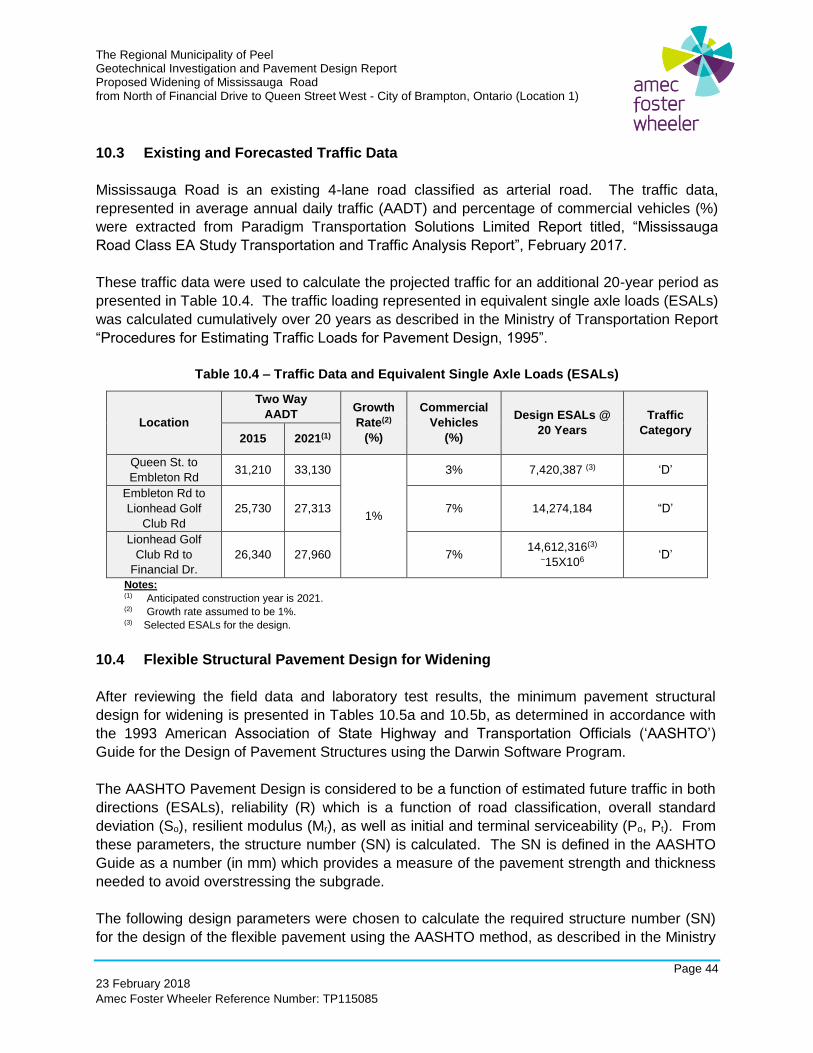
The Regional Municipality of Peel Geotechnical Investigation and Pavement Design Report Proposed Widening of Mississauga Road from North of Financial Drive to Queen Street West - City of Brampton, Ontario (Location 1)
Page 44
23 February 2018
Amec Foster Wheeler Reference Number: TP115085
10.3 Existing and Forecasted Traffic Data
Mississauga Road is an existing 4-lane road classified as arterial road. The traffic data,
represented in average annual daily traffic (AADT) and percentage of commercial vehicles (%)
were extracted from Paradigm Transportation Solutions Limited Report titled, “Mississauga
Road Class EA Study Transportation and Traffic Analysis Report”, February 2017.
These traffic data were used to calculate the projected traffic for an additional 20-year period as
presented in Table 10.4. The traffic loading represented in equivalent single axle loads (ESALs)
was calculated cumulatively over 20 years as described in the Ministry of Transportation Report
“Procedures for Estimating Traffic Loads for Pavement Design, 1995”.
Table 10.4 – Traffic Data and Equivalent Single Axle Loads (ESALs)
Location
Two Way
AADT Growth
Rate(2)
(%)
Commercial
Vehicles
(%)
Design ESALs @
20 Years
Traffic
Category 2015 2021(1)
Queen St. to
Embleton Rd 31,210 33,130
1%
3% 7,420,387 (3) ‘D’
Embleton Rd to
Lionhead Golf
Club Rd
25,730 27,313 7% 14,274,184 “D’
Lionhead Golf
Club Rd to
Financial Dr.
26,340 27,960 7% 14,612,316(3)
~15X106 ‘D’
Notes: (1) Anticipated construction year is 2021. (2) Growth rate assumed to be 1%. (3) Selected ESALs for the design.
10.4 Flexible Structural Pavement Design for Widening
After reviewing the field data and laboratory test results, the minimum pavement structural
design for widening is presented in Tables 10.5a and 10.5b, as determined in accordance with
the 1993 American Association of State Highway and Transportation Officials (‘AASHTO’)
Guide for the Design of Pavement Structures using the Darwin Software Program.
The AASHTO Pavement Design is considered to be a function of estimated future traffic in both
directions (ESALs), reliability (R) which is a function of road classification, overall standard
deviation (So), resilient modulus (Mr), as well as initial and terminal serviceability (Po, Pt). From
these parameters, the structure number (SN) is calculated. The SN is defined in the AASHTO
Guide as a number (in mm) which provides a measure of the pavement strength and thickness
needed to avoid overstressing the subgrade.
The following design parameters were chosen to calculate the required structure number (SN)
for the design of the flexible pavement using the AASHTO method, as described in the Ministry
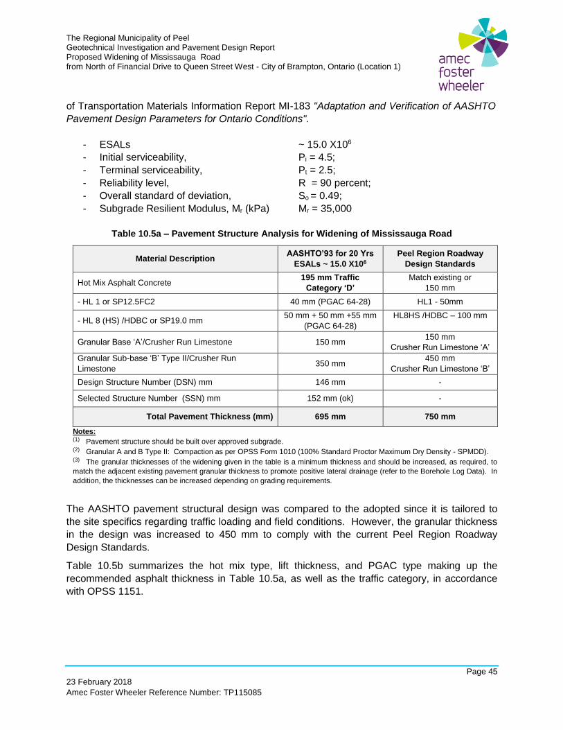
The Regional Municipality of Peel Geotechnical Investigation and Pavement Design Report Proposed Widening of Mississauga Road from North of Financial Drive to Queen Street West - City of Brampton, Ontario (Location 1)
Page 45
23 February 2018
Amec Foster Wheeler Reference Number: TP115085
of Transportation Materials Information Report MI-183 "Adaptation and Verification of AASHTO
Pavement Design Parameters for Ontario Conditions".
- ESALs ~ 15.0 X10⁶
- Initial serviceability, Pi = 4.5;
- Terminal serviceability, Pt = 2.5;
- Reliability level, R = 90 percent;
- Overall standard of deviation, So = 0.49;
- Subgrade Resilient Modulus, Mr (kPa) Mr = 35,000
Table 10.5a – Pavement Structure Analysis for Widening of Mississauga Road
Material Description AASHTO’93 for 20 Yrs
ESALs ~ 15.0 X10⁶
Peel Region Roadway
Design Standards
Hot Mix Asphalt Concrete 195 mm Traffic
Category ‘D’
Match existing or
150 mm
- HL 1 or SP12.5FC2 40 mm (PGAC 64-28) HL1 - 50mm
- HL 8 (HS) /HDBC or SP19.0 mm 50 mm + 50 mm +55 mm
(PGAC 64-28)
HL8HS /HDBC – 100 mm
Granular Base ‘A’/Crusher Run Limestone 150 mm 150 mm
Crusher Run Limestone ‘A’
Granular Sub-base ‘B’ Type II/Crusher Run
Limestone 350 mm
450 mm
Crusher Run Limestone ‘B’
Design Structure Number (DSN) mm 146 mm -
Selected Structure Number (SSN) mm 152 mm (ok) -
Total Pavement Thickness (mm) 695 mm 750 mm
Notes: (1) Pavement structure should be built over approved subgrade. (2) Granular A and B Type II: Compaction as per OPSS Form 1010 (100% Standard Proctor Maximum Dry Density - SPMDD). (3) The granular thicknesses of the widening given in the table is a minimum thickness and should be increased, as required, to
match the adjacent existing pavement granular thickness to promote positive lateral drainage (refer to the Borehole Log Data). In
addition, the thicknesses can be increased depending on grading requirements.
The AASHTO pavement structural design was compared to the adopted since it is tailored to
the site specifics regarding traffic loading and field conditions. However, the granular thickness
in the design was increased to 450 mm to comply with the current Peel Region Roadway
Design Standards.
Table 10.5b summarizes the hot mix type, lift thickness, and PGAC type making up the
recommended asphalt thickness in Table 10.5a, as well as the traffic category, in accordance
with OPSS 1151.
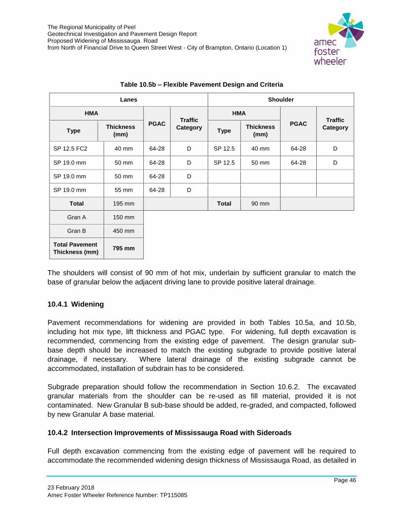
The Regional Municipality of Peel Geotechnical Investigation and Pavement Design Report Proposed Widening of Mississauga Road from North of Financial Drive to Queen Street West - City of Brampton, Ontario (Location 1)
Page 46
23 February 2018
Amec Foster Wheeler Reference Number: TP115085
Table 10.5b – Flexible Pavement Design and Criteria
Lanes Shoulder
HMA
PGAC Traffic
Category
HMA
PGAC Traffic
Category Type
Thickness
(mm) Type
Thickness
(mm)
SP 12.5 FC2 40 mm 64-28 D SP 12.5 40 mm 64-28 D
SP 19.0 mm 50 mm 64-28 D SP 12.5 50 mm 64-28 D
SP 19.0 mm 50 mm 64-28 D
SP 19.0 mm 55 mm 64-28 D
Total 195 mm Total 90 mm
Gran A 150 mm
Gran B 450 mm
Total Pavement
Thickness (mm) 795 mm
The shoulders will consist of 90 mm of hot mix, underlain by sufficient granular to match the
base of granular below the adjacent driving lane to provide positive lateral drainage.
10.4.1 Widening
Pavement recommendations for widening are provided in both Tables 10.5a, and 10.5b,
including hot mix type, lift thickness and PGAC type. For widening, full depth excavation is
recommended, commencing from the existing edge of pavement. The design granular sub-
base depth should be increased to match the existing subgrade to provide positive lateral
drainage, if necessary. Where lateral drainage of the existing subgrade cannot be
accommodated, installation of subdrain has to be considered.
Subgrade preparation should follow the recommendation in Section 10.6.2. The excavated
granular materials from the shoulder can be re-used as fill material, provided it is not
contaminated. New Granular B sub-base should be added, re-graded, and compacted, followed
by new Granular A base material.
10.4.2 Intersection Improvements of Mississauga Road with Sideroads
Full depth excavation commencing from the existing edge of pavement will be required to
accommodate the recommended widening design thickness of Mississauga Road, as detailed in
The Regional Municipality of Peel Geotechnical Investigation and Pavement Design Report Proposed Widening of Mississauga Road from North of Financial Drive to Queen Street West - City of Brampton, Ontario (Location 1)
Page 47
23 February 2018
Amec Foster Wheeler Reference Number: TP115085
Tables 10.5a, and 10.5b. Sub-base can vary in thickness to match the adjacent existing
pavement granular in order to promote positive lateral drainage.
The existing granular fill material from the shoulder may be stockpiled and re-used as granular
sub-base provided that it is not contaminated.
10.5 Rehabilitation of Existing Pavement
Given that roadway will be widened and the existing pavement condition is rated as “Good” to
“Fairly Good” condition, it is recommended that the existing surface course be milled and
resurfaced to a depth of 40 mm commencing from the centerline of the roadway to the outside
edge of pavement on the side of the roadway that is to be widened.
10.6 General Construction Comments for Pavement
10.6.1 Recommended Rehabilitation Strategy
For the existing pavement, mill 40 mm and overlay 40 mm is recommended (without grade
raise).
10.6.2 Subgrade Preparation
The long-term performance of pavement structure is highly dependent on the subgrade support
conditions. To prepare the subgrade for road widening, the existing topsoil and vegetation
should be stripped and the area should be graded according to OPSS 206 (Construction
Specification for Grading).
Fill, if required for site grading in the widening areas, should be placed as compacted fill to
provide competent subgrade. The fill should be placed in lifts and each lift should be uniformly
compacted as in OPSS 501 (Construction Specification for Compacting).
Subgrade preparation should not be done in the winter. Drainage layers and/or subdrains
should be designed and installed to prevent any water accumulation under pavement surface at
all times. The final subgrade surface should be sloped at least 3 % to drain towards the
subdrain system or drainage ditches.
The subsoils at this site are generally fine grained which are considered frost susceptible. These
soils will become weakened when subject to traffic and when wet. If site work is carried out
during periods of wet weather, the subgrade will be easily disturbed. Under inclement weather
conditions, an adequate granular working surface would be required to minimize disturbance
and protect the integrity of the subgrade soils.
The Regional Municipality of Peel Geotechnical Investigation and Pavement Design Report Proposed Widening of Mississauga Road from North of Financial Drive to Queen Street West - City of Brampton, Ontario (Location 1)
Page 48
23 February 2018
Amec Foster Wheeler Reference Number: TP115085
Construction traffic over exposed subgrade should be minimised and temporary construction
hauling routes should be established. If these routes coincide with future paved areas,
adequately reinforced haul roads (increased thickness of granular base, geosynthetics, etc.)
should be constructed to reduce disturbance to the subgrade soils. These provisions are
particularly important if the construction is scheduled during wet and cold seasons.
10.6.3 Drainage
For new construction or rehabilitation, adequate drainage should be provided both laterally and
longitudinally along the length of the road section. Where a rural cross-section is proposed, the
sub-base granular should extend across the full width of the roadway and should daylight in the
ditches. If drainage through granular soils underneath pavement is considered not sufficient,
subdrains should be installed. However, if installed, the subdrains should be placed parallel to
the road edges, at the subgrade level and connected to the catch basins as shown on Subdrain
Pipe – Connection and Outlet – OPSD 216.021.
Continuity of drainage through the granular road base and sub-base layers should be
maintained between the existing and new pavement structures. In this regard, the granular
thickness for new pavement structure may have to be adjusted to match the granular fill
encountered under the existing pavement, but should not be less the depth recommended
herein.
A minimum slope of 2 % or Region's standards should be maintained across the paved sections
(finished road surface) for proper surface drainage. New pavement should slope towards
gutter/ditch.
10.6.4 Hot Mixes and PGAC Type
The following hot mixes should be used on roadways: HL 8(HS) or HDBC or SP19.0 mm binder
course and HL 1 or SP12.5 FC2 surface course mix, to provide the roadway with high durability.
Material Specifications for Superpave hot mix asphalt should be as per OPSS 1151 (Material
Specification for Superpave and Stone Mastic Asphalt Mixtures).
Typically, performance graded asphalt cement PGAC 58-28 would be specified for the Region
of Southwest Ontario. However, performance graded asphalt cement of PGAC 64-28 is
recommended for Superpave surface course and binder courses. This PGAC should satisfy the
requirements of MP1 of SHRP Specifications for Superpave. It should be noted that PGAC is
engineered asphalt cement with additives such as polymers or modifiers so as to accommodate
a wide range of pavement temperatures. When PGAC is used, it is recommended that the
steel-wheel rollers are thinly coated with light application of non-petroleum based, wetting agent
(soap solution) to reduce sticking of the mix to the compaction equipment.
The Regional Municipality of Peel Geotechnical Investigation and Pavement Design Report Proposed Widening of Mississauga Road from North of Financial Drive to Queen Street West - City of Brampton, Ontario (Location 1)
Page 49
23 February 2018
Amec Foster Wheeler Reference Number: TP115085
Transition Treatments at Limits of Paving: At the limits of the project, a butt joint with the existing
pavement is recommended. The butt joint between successive lifts of hot mix should be
staggered at a distance of not less than 5 m, in accordance with OPSS 313 (Construction
Specification for Hot Mixt Asphalt – End Result). It should be ensured that no joint location
corresponds with a joint location in any other layer.
10.6.5 In-Situ Compaction for Hot Mix
In all areas, asphaltic concrete should be compacted as per OPSS 310 (Construction
Specification for Hot Mix Asphalt – End Result) - Table 10. It should be noted that the granular
base and sub-base materials should be compacted as OPSS 310 (Construction Specification
for Hot Mixt Asphalt)–Table 10.
Field Quality Assurance: Plate samples of loose hot mix should be obtained for each paving
day, and extraction/gradation and full hot mix compliance testing should be carried out on these
samples. The finished surface should be true to required and cross-section within 6 mm from
required elevations and thickness. The surface should show no depressions or bumps
exceeding 3 mm under a 3.0 m long straight edge, placed parallel to the road centre line as per
OPSS 310 (Construction Specification for Hot Mixt Asphalt – End Result).
10.6.6 Asphalt Removal and Recycled Materials
The milled/reclaimed asphalt may be recycled and blended with granular sub-base materials to
be used on the shoulders during the new construction for widening. The maximum amounts (%)
of reclaimed asphalt pavement to be incorporated in the pavement are included in the
OPS.MUNI 1010 (Material Specification for Aggregates – Base, Sub-base, Select Subgrade,
and Backfill Material). RAP containing steel slag aggregates are not used as per OPSS MUNI
1010 (Material Specification for Aggregates – Base, Sub-base, Select Subgrade, and Backfill
Material).
10.6.7 Stripping and Sub-Excavation
Stripping of organic matter and topsoil (ranging in thickness from 0 to 300 mm) is required within
the widening limits. In addition, any unsuitable soft or saturated material should be sub-
excavated and replaced with competent materials.
10.6.8 Sidewalk Construction
The sidewalks would be constructed on the new embankment (granular base) in the fill area and
on the existing fill or natural soil (subgrade) in the cut areas. Construction of sidewalk should be
in accordance with OPSD 310.010 (Concrete Sidewalk) and/or OPSD 310.020 (Concrete
Sidewalk Adjacent to Curb and Gutter), unless otherwise stated in the Region Standards and/or
contract specifications. The fill subgrade/granular base should be inspected prior to placement

The Regional Municipality of Peel Geotechnical Investigation and Pavement Design Report Proposed Widening of Mississauga Road from North of Financial Drive to Queen Street West - City of Brampton, Ontario (Location 1)
Page 50
23 February 2018
Amec Foster Wheeler Reference Number: TP115085
of the sidewalk. Soft areas in the subgrade, if any, should be re-compacted (if applicable) or
replaced and compacted. OPSS 501 (Construction Specification for Compacting) and/or the
Region's Standards should be followed for compaction requirements. Quality control and
quality assurance should be implemented according to the Region's Standards.
11.0 GENERAL CONSIDERATION FOR DESIGN AND CONSTRUCTION
11.1 Site Preparation
Site preparation should generally include stripping of topsoil, excavation to subgrade, proof-
rolling, repairing soft spots, if encountered, and backfilling, if necessary with engineered fill in
order to support the proposed structures.
11.2 Engineered Fill
Engineered fill, where required, may be used to backfill excavated areas, backfill behind
retaining walls / abutments, replace soft/incompetent soils, and/or raise grades. Engineered fill
for embankment and backfill of excavated areas should be placed after stripping any soils
containing excessive organic matters, the existing fill soils and otherwise unsuitable soils.
Engineered fill should be prepared according to the Region’ standards / contract specifications,.
General guideline for preparation of engineered fill is described below:
▪ Engineered fill should extend a minimum of 1.0 m beyond the perimeter of the structure
footprint to be supported, where applicable.
▪ Topsoil, organic matter, and other compressible, weak and deleterious materials should
be stripped and or sub-excavated and replaced with compactable approved soil.
▪ The fill material should be placed and compacted as per OPSS 501 (Construction
Specification for Compacting) and/or applicable Region standards.
▪ For a certifiable engineered fill, full-time geotechnical inspection and quality control are
necessary.
▪ Fill material should not be frozen during backfill and compaction.
▪ Water content of the fill should be within 2 % of the optimum value for compaction.
11.3 Excavation and Dewatering
Temporary excavations should be carried out in accordance with the Ontario Health and Safety
Regulations for Construction Projects. Based on the soil conditions encountered in the
boreholes, the soils to be excavated can be classified as follows:
The Regional Municipality of Peel Geotechnical Investigation and Pavement Design Report Proposed Widening of Mississauga Road from North of Financial Drive to Queen Street West - City of Brampton, Ontario (Location 1)
Page 51
23 February 2018
Amec Foster Wheeler Reference Number: TP115085
Existing fill soils Type 3
Loose to compact silty sand / sandy silt / sand Type 3
Dense to very dense silty sand / sandy silt / sand Type 2
Dense to very dense sandy gravel / gravelly sand / sand and gravel Type 2
Very dense silty sand / sandy silt till Type 2
Hard silty clay / clayey silt till, weathered shale Type 2
A bank slope of 1H:1V is required for excavations in Type 2 and Type 3 soils in accordance with
the Ontario Health and Safety Regulations. For Type 2 soils, a 1.2 m high vertical cut at the
bottom of excavation may generally be constructed. However, a 1.2 m high vertical cut under
the groundwater table may not be stable and flatter slopes may be required. Also, near the
ground surface, occasional 3H:1V slopes may be required due to possible loose/soft surficial
soils. All excavations should be inspected and the exposed soil types should be confirmed by a
geotechnical engineer.
For all cut slopes, the stability should be frequently monitored by a geotechnical engineer. If the
cut slopes are subject to erosion (e.g., due to rainfall, high groundwater flow, etc.), slope
stabilization measures (e.g., covering the slope/trench faces with plastic sheets, excavating
flatter slope, etc.) should be implemented.
Stockpiles of excavated materials should be kept at least a horizontal distance equal to the
depth of excavation from the top edge of the excavation or slope to prevent slope instability,
subject to confirmation by a geotechnical engineer.
The terms describing the consistency (very stiff or hard) give an indication of the effort needed
for excavation. Hard natural soils encountered in the boreholes, along with weathered shale,
may require additional excavation effort/equipment (e.g., impact hammer, excavation with
rippers, etc.). Such a possibility should be considered by the Contractor and construction
contract.
Groundwater in excavations may be present and dewatering may be required for underground
utility installation. Dewatering (where required) could be carried out, in general, by a system of
sumps and pumps or gravity drainage. High water flow rates may be encountered during the
course of the installation in sandy / gravelly soils and the dewatering effort could require an
increased number of sumps and pumps. More information regarding the dewatering and
hydrogeological condition of the site is provided in the hydrogeological report submitted under a
separate cover.
OPSS 517 (Construction Specification for Dewatering of Pipeline, Utility and Associates
Structure Excavation) should be followed to keep the excavations free of water during
installation of underground utilities.
The Regional Municipality of Peel Geotechnical Investigation and Pavement Design Report Proposed Widening of Mississauga Road from North of Financial Drive to Queen Street West - City of Brampton, Ontario (Location 1)
Page 52
23 February 2018
Amec Foster Wheeler Reference Number: TP115085
Excavating and backfilling should be carried in accordance with OPSS 902 (Construction
Specification for Excavating and Backfilling - Structures).
If open cut cannot be carried out, a shoring system may be used to limit the extent of
excavations, subject to engineering design and approval. Temporary protection systems, if
required, should follow OPSS 539 (Construction Specification for Temporary Protection
System).
Where there is insufficient space for open cut excavations, shoring or a trench box will be
required. The shoring analysis and design should be carried out in accordance with the
Canadian Foundation Engineering Manual, latest Edition. Soil parameter provided in Section
9.0 may be used for design of temporary shoring system.
It is recommended that qualified geotechnical personnel be present during the excavations to
review the condition of excavations.
11.4 Soil Reuse and Backfill
The soils removed by excavation would consist of sand and gravel fill, silty sand fill and natural
sand and gravel, sand, silty sand or silty clay / clayey silt till. The excavated soil may be used
as backfill, if it is clean and without organic matter and approved by geotechnical engineer.
The water contents of the fill soils at the time of backfilling and compaction should be at or near
optimum (normally ± 2% of optimum water content). The excavated soils may require
reconditioning (e.g., drying) prior to reuse. Unsuitable materials such as organic soils, boulders,
cobbles, frozen soils, etc., should not be used for backfilling. The backfill should be placed in
maximum 300 mm thick layers and each layer should be compacted to at least 95 % Standard
Proctor Maximum Dry Density (SPMDD). When compacting, care should be taken to prevent
damage to the pipes / manholes / catch basins. Backfilling and compacting should be carried
out in accordance with OPSS 401 (Construction Specification for Trenching, Backfilling and
Compacting) and OPSS 501 (Compacting).
Backfill materials behind the bridge, or behind the proposed retaining walls should consist of
non-frost susceptible, free-draining granular materials in accordance with OPSS 1010 –
(Material Specification for Aggregates – Base, Sub-base, Select Subgrade, and Backfill
Material) (i.e., Granular ‘A’ or Granular ‘B’).
Free-draining backfill materials and drain pipes and weep holes, etc. should be provided to
prevent hydrostatic pressure build-up behind structures.
The Regional Municipality of Peel Geotechnical Investigation and Pavement Design Report Proposed Widening of Mississauga Road from North of Financial Drive to Queen Street West - City of Brampton, Ontario (Location 1)
Page 53
23 February 2018
Amec Foster Wheeler Reference Number: TP115085
11.5 Soil Corrosivity
Two (2) soil samples from Boreholes BH 13 and BH B3 were tested to assess the corrosive
potential of soil with respect to steel and concrete by determination of pH, soluble chloride,
soluble sulphate, electrical conductivity and resistivity. The soil corrosivity analysis was carried
out by AGAT Laboratories.
The corrosivity analysis results are summarized in Table 11.1. The complete laboratory test
results and the Certificates of Analyses are included in Appendix C.
Table 11.1 –Soil Corrosivity Test Results
Sample ID Resistivity
(ohm-cm)
Chloride
(μg/g)
Electrical
Conductivity
(mS/cm)
pH Sulphate
(μg/g)
Redox
Potential
(mV)
BH 13, SS 4 1140 338 0.694 9.92 20 129
BH B3, SS 6 346 1730 2.89 9.03 70 153
Compared to the values in the available literature (i.e., J.D. Palmer, “Soil Resistivity
Measurement and Analysis”, Materials Performance, Volume 13, 1974), the above-mentioned
values of the soil resistivity should be considered as “severe to very severe” for exposed
metallic structures.
The measured water-soluble sulphate in soil were 20 µg/g and 70 µg/g. In accordance with
Table 3 of the Canadian Standards Association (CSA) Series CSA A23.1-09, soil with the
sulphate content ratio less than 0.1% (i.e., 1,000 ppm or µg/g) is not considered aggressive to
concrete. Therefore, in accordance with Table 6 of the CSA Series A23.1-09, Type GU
Portland cement may be used for concrete.
Soil corrosivity should be assessed by a corrosivity expert, if necessary.
12.0 LIMITED SOIL CHEMICAL ANALYSES
12.1 Soil Sampling
The environmental component of the subsurface investigation included the following activities:
• Conducting the soil sampling activities in accordance with Ontario Ministry of Environment
and Climate Change (MOECC) documents entitled “Guide for Completing Phase Two
Environmental Site Assessments under Ontario Regulation 153/04” (March 2016), “Protocol
for Analytical Methods Used in the Assessment of Properties Under Part XV.1 of the
Environmental Protection Act” (June 2011) and Ontario Regulation 153/04;
The Regional Municipality of Peel Geotechnical Investigation and Pavement Design Report Proposed Widening of Mississauga Road from North of Financial Drive to Queen Street West - City of Brampton, Ontario (Location 1)
Page 54
23 February 2018
Amec Foster Wheeler Reference Number: TP115085
• Soil samples were submitted for laboratory analysis of petroleum hydrocarbons (PHC) F1-
F4, volatile organic compounds (VOCs), metals and inorganics and organochlorine
pesticides (OCPs) to assist in determining appropriate soil disposal options, if required,
during construction;
• Submission of one (1) soil sample for Ontario Regulation 347 as amended by Ontario
Regulation 558/00 (O. Reg. 347) Toxicity Characteristic Leaching Procedure (TCLP) for
volatile organic compounds (VOCs), ignitibility and metals and inorganics to determine
landfill acceptability of soil/granular fill originating from the Site;
• Comparison of the laboratory analytical results to soil standards presented in the MOECC
document entitled “Soil, Ground Water and Sediment Standards for Use Under Part XV.1 of
the Environmental Protection Act,” dated April 15, 2011 and O. Reg. 347, as amended by O.
Reg. 558/00, Schedule 4 Leachate Quality Criteria provided in the MOECC document
entitled “Registration Guidance Manual For Generators of Liquid Industrial and Hazardous
Waste,” October 2000 (the “Schedule 4 Criteria”).
12.1.1 Site Condition Standards
Soil results are compared to the MOECC Table 1 soil standards for Residential/ Parkland/
Institutional/ Industrial/ Commercial/ Community Property Use (Table 1 SCS) and Table 3 soil
standards for Industrial / Commercial / Community Property Use (Table 3 SCS) presented in the
MOECC document “Soil, Ground Water and Sediment Standards for Use Under Part XV.1 of
the Environmental Protection Act”, dated April 15, 2011.
12.1.2 Sample Analysis Rationale
A total of fifteen (15) soil samples were collected for geotechnical purposes and submitted for
analysis of metals and inorganics as shown in Table 12.1. Four (4) samples were submitted for
analysis of PHC F1 to F4, VOCs and OCP.
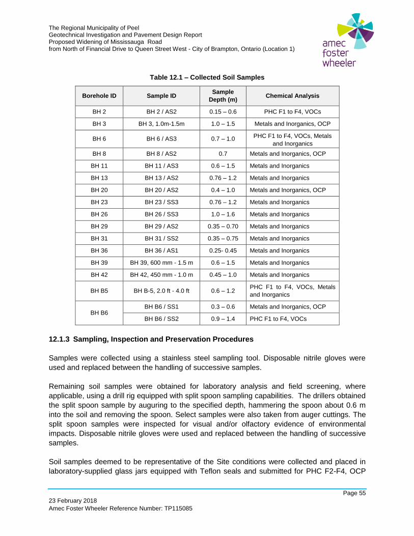
The Regional Municipality of Peel Geotechnical Investigation and Pavement Design Report Proposed Widening of Mississauga Road from North of Financial Drive to Queen Street West - City of Brampton, Ontario (Location 1)
Page 55
23 February 2018
Amec Foster Wheeler Reference Number: TP115085
Table 12.1 – Collected Soil Samples
Borehole ID Sample ID Sample
Depth (m) Chemical Analysis
BH 2 BH 2 / AS2 0.15 – 0.6 PHC F1 to F4, VOCs
BH 3 BH 3, 1.0m-1.5m 1.0 – 1.5 Metals and Inorganics, OCP
BH 6 BH 6 / AS3 0.7 – 1.0 PHC F1 to F4, VOCs, Metals
and Inorganics
BH 8 BH 8 / AS2 0.7 Metals and Inorganics, OCP
BH 11 BH 11 / AS3 0.6 – 1.5 Metals and Inorganics
BH 13 BH 13 / AS2 0.76 – 1.2 Metals and Inorganics
BH 20 BH 20 / AS2 0.4 – 1.0 Metals and Inorganics, OCP
BH 23 BH 23 / SS3 0.76 – 1.2 Metals and Inorganics
BH 26 BH 26 / SS3 1.0 – 1.6 Metals and Inorganics
BH 29 BH 29 / AS2 0.35 – 0.70 Metals and Inorganics
BH 31 BH 31 / SS2 0.35 – 0.75 Metals and Inorganics
BH 36 BH 36 / AS1 0.25- 0.45 Metals and Inorganics
BH 39 BH 39, 600 mm - 1.5 m 0.6 – 1.5 Metals and Inorganics
BH 42 BH 42, 450 mm - 1.0 m 0.45 – 1.0 Metals and Inorganics
BH B5 BH B-5, 2.0 ft - 4.0 ft 0.6 – 1.2 PHC F1 to F4, VOCs, Metals
and Inorganics
BH B6 BH B6 / SS1 0.3 – 0.6 Metals and Inorganics, OCP
BH B6 / SS2 0.9 – 1.4 PHC F1 to F4, VOCs
12.1.3 Sampling, Inspection and Preservation Procedures
Samples were collected using a stainless steel sampling tool. Disposable nitrile gloves were
used and replaced between the handling of successive samples.
Remaining soil samples were obtained for laboratory analysis and field screening, where
applicable, using a drill rig equipped with split spoon sampling capabilities. The drillers obtained
the split spoon sample by auguring to the specified depth, hammering the spoon about 0.6 m
into the soil and removing the spoon. Select samples were also taken from auger cuttings. The
split spoon samples were inspected for visual and/or olfactory evidence of environmental
impacts. Disposable nitrile gloves were used and replaced between the handling of successive
samples.
Soil samples deemed to be representative of the Site conditions were collected and placed in
laboratory-supplied glass jars equipped with Teflon seals and submitted for PHC F2-F4, OCP
The Regional Municipality of Peel Geotechnical Investigation and Pavement Design Report Proposed Widening of Mississauga Road from North of Financial Drive to Queen Street West - City of Brampton, Ontario (Location 1)
Page 56
23 February 2018
Amec Foster Wheeler Reference Number: TP115085
and/or metals & inorganics. Samples submitted for analysis of VOCs and PHC F1 were
collected using dedicated laboratory supplied syringes and preserved in the field using 40 mL
vials containing 10 mL of methanol. The samples were selected on the basis of visual/olfactory
evidence of impacts, field screening results, or from the vicinity of the apparent water table. All
samples were stored in coolers, on ice, immediately after collection and during transport to the
laboratory.
Using nitrile gloves, the remaining sample, where applicable, was transferred from the split
spoon sampler into clean (i.e., unused) resealable bags. Prior to measurement of soil
headspace vapours, the bags were allowed to reach ambient temperature. Soil vapours in
collected soil samples were measured with a RKI Eagle 2 portable gas meter. The RKI Eagle 2
was calibrated at the commencement of the field sampling programs using isobutylene
reference gas and hexane reference gas. The duplicate soil sample fractions were screened for
both combustible organic vapour (COV) and total organic vapour (TOV) concentrations using
the sample headspace method to facilitate sample selections for laboratory analysis and to
provide an assessment of the vertical contaminant distributions at each borehole location, if
applicable.
Representative soil samples collected during the investigation were submitted to AGAT
Laboratories of Mississauga, Ontario, for PHC F1-F4, VOCs, OCPs and metals and inorganics
analysis. AGAT is accredited by the Standards Council of Canada (“SCC”) and the Canadian
Association for Laboratory Accreditation (CALA) in accordance with ISO/IEC 17025:2005 –
“General Requirements for the Competence of Testing and Calibration Laboratories” for the
tested parameters set out in the Soil, Ground Water and Sediment Standards.
It should be noted that a Phase I ESA for the project area has not been conducted by or
provided to Amec Foster Wheeler and therefore historical land use has not been confirmed.
12.2 Environmental Test Results And Considerations
12.2.1 Chemical Results
No evidence (i.e. visual/olfactory) of environmental impacts were observed in any of the soil
samples collected from the project area. Field screening measurements of combustible and total
organic gas vapours undertaken with the Gastector or RKI Eagle 2 are provided on the soil
analytical tables. The readings ranged from non-detectable to 35 parts per million (ppm) for
COV and 5 ppm for TOV. Soil vapour readings were used in the selection of soil samples for
analysis.
A total of fifteen (15) soil samples were collected for geotechnical purposes and submitted for
analysis of metals and inorganics. Four (4) samples were submitted for analysis of PHC F1 to
F4, VOCs and OCP. Samples were submitted from depths between surface and 1.5 m based
The Regional Municipality of Peel Geotechnical Investigation and Pavement Design Report Proposed Widening of Mississauga Road from North of Financial Drive to Queen Street West - City of Brampton, Ontario (Location 1)
Page 57
23 February 2018
Amec Foster Wheeler Reference Number: TP115085
on measured gas vapours (where available), proximity to the inferred water table, presence of
fill material and depth of construction works.
The soil/crushed rock samples collected or reviewed as part of this assessment that exceeded
the Table 1 SCS are as follows:
• BH B6 / SS2 exceeded for PHC F4 at a depth of 0.9 to 1.4 m.
• BH 3, 1.0m-1.5m exceeded for sodium adsorption ratio (SAR) at a depth of 1.0 to 1.5 m.
• BH 8/AS2 exceeded for SAR at a depth of 0.7 to 1.0 m.
• BH 11/AS3 exceeded for SAR at a depth of 0.6 to 1.5 m.
• BH 13/AS2 exceeded for SAR and electrical conductivity (EC) at a depth of 0.76 to 1.2
m.
• BH 20/AS2 exceeded for SAR at a depth of 0.4 to 1.0 m.
• BH 23/SS3 exceeded for SAR at a depth of 0.76 to 1.2 m.
• BH 26/SS3 exceeded for SAR and EC at a depth of 1.0 to 1.6 m.
• BH 29/AS2 exceeded for SAR and EC at a depth of 0.35 to 0.70 m.
• BH 31/SS2 exceeded for SAR and EC at a depth of 0.35 to 0.75 m.
• BH 36/AS1 exceeded for SAR at a depth of 0.25 to 0.45 m.
• BH B-5, 2.0 ft-4.0 ft exceeded for SAR and EC at a depth of 0.6 to 1.2 m.
• BH B6/SS1 exceeded for SAR at a depth of 0.3 to 0.6 m.
The remaining soil samples met the Table 1 SCS for PHC F1 to F4, VOCs, OCP and metals
and inorganics.
The soil/crushed rock samples collected or reviewed as part of this assessment that exceeded
the Table 3 SCS are as follows:
• BH 13/AS2 exceeded for SAR and EC at a depth of 0.76 to 1.2 m.
• Samples BH 23/SS3, BH 29/AS2 and BH 31/SS2 were above the pH range of 5 to 9 for
surface soil to be able to apply Table 3 SCS under O. Reg. 153/04. The elevated pH is
not considered to be hazardous for disposal at a licensed landfill.
The remaining soil samples met the Table 3 SCS for PHC F1 to F4, VOCs, OCPs and metals
and inorganics. Due to the application of road salts for control of snow and ice on roads, it is
common to find elevated concentrations of EC and SAR and therefore these parameters would
be exempt under O. Reg.153/04 (O. Reg. 153/04 s. 48(3)).
The reported leachate concentrations were compared to the Schedule 4 Criteria. The reported
concentrations of metals & inorganics and VOCs, were below the Schedule 4 Leachate Quality

The Regional Municipality of Peel Geotechnical Investigation and Pavement Design Report Proposed Widening of Mississauga Road from North of Financial Drive to Queen Street West - City of Brampton, Ontario (Location 1)
Page 58
23 February 2018
Amec Foster Wheeler Reference Number: TP115085
Criteria and it was noted as non-flammable; therefore, the soil would be classified as non-
hazardous for disposal at an approved landfill.
If soil is required to be removed from the site it should be disposed at a licensed landfill or
equivalent receiving facility.
Analytical results are summarized in Tables 1 to 4 along with the laboratory certificates of
analysis and provided in Appendix C. The results of the O. Reg. 347 TCLP analysis and
associated laboratory certificate of analysis are provided in Appendix D.
12.2.2 Laboratory Quality Control
The “Protocol for Analytical Methods Used in the Assessment of Properties under Part XV.1 of
the Environmental Protection Act”, 01 July 2011 (the “2011 Analytical Protocol”) provides
requirements for sample handling and storage requirements, reporting requirements, analytical
methods and QA/QC procedures for analytical parameters.
A low bias might be present in cyanide, chromium VI and mercury sample results as the
samples were analyzed past hold times. These parameters are not considered to be potential
contaminants of concern and therefore the low bias is not considered to significantly affect the
outcome of this assessment. Remaining samples/sample extracts were analyzed within their
applicable hold times using approved analytical methods.
The reporting limits were met for all samples and tested parameters. No tested parameter was
present in a detectable concentration in any laboratory Method Blank and all laboratory
surrogates, reference materials and replicate samples are considered acceptable.
13.0 RECOMMENDATIONS FOR ADDITIONAL INVESTIGATION FOR DETAIL DESIGN
This geotechnical investigation was completed for Schedule 'C' Class Environmental
Assessment. Additional investigation, including boreholes and / or analysis, may be required for
detail design, once the design details are available. The following additional investigation /
analysis should be carried out, for detail design:
➢ field investigation, including additional boreholes, for any additional structures not
identified during this investigation; and
➢ slope stability analysis for:
o retaining walls / abutment slopes, during detail design;
o high embankments (height greater than or equal to 4.5 m); and
o permanent cut slopes.
The Regional Municipality of Peel Geotechnical Investigation and Pavement Design Report Proposed Widening of Mississauga Road from North of Financial Drive to Queen Street West - City of Brampton, Ontario (Location 1)
Page 59
23 February 2018
Amec Foster Wheeler Reference Number: TP115085
14.0 CLOSURE
The sub-surface information and recommendations contained in this report should be used
solely for the purpose of geotechnical assessment of the project.
Additional borehole investigation and analyses may be required to fulfill the final design
requirements.
The Report Limitations are an integral part of this report.
This report was prepared by Shami Malla, M.Civ.Eng., Hoda Seddik, M.A.Sc, P.Eng and Tracey
Schranz, B.E.S., and reviewed by Jeff Carson, P.Eng. and Prapote Boonsinsuk, Ph.D., P.Eng.
Sincerely,
Amec Foster Wheeler Environment & Infrastructure,
a Division of Amec Foster Wheeler Americas Limited
Shami Malla, M. Civ. Eng., P.Eng. Tracey Schranz, B.E.S.
Geotechnical Engineer Environmental Site Assessor
Hoda Seddik, M.A.Sc., P.Eng.
Consulting Engineer
Senior Associate Pavement Engineer
Amec Foster Wheeler Environment & Infrastructure,
a Division of Amec Foster Wheeler Americas Limited
REPORT LIMITATIONS
The conclusions and recommendations given in this report are based on information determined
at the test hole locations. The information contained herein in no way reflects on the
environmental aspects of the project, unless otherwise stated. Subsurface and groundwater
conditions between and beyond the test holes may differ from those encountered at the test
hole locations, and conditions may become apparent during construction, which could not be
detected or anticipated at the time of the site investigation. It is recommended practice that the
Geotechnical Engineer be retained during the construction to confirm that the subsurface
conditions across the site do not deviate materially from those encountered in the test holes.
The design recommendations given in this report are applicable only to the project described in
the text, and then only if constructed substantially in accordance with the details stated in this
report. Since all details of the design may not be known, it is recommended that Amec Foster
Wheeler Environment & Infrastructure, a Division of Amec Foster Wheeler Americas Limited be
retained during the final design stage to verify that the design is consistent with Amec Foster
Wheeler Environment & Infrastructure’s recommendations, and that assumptions made in Amec
Foster Wheeler Environment & Infrastructure, are valid.
The comments made in this report relating to potential construction problems and possible
methods of construction are intended only for the guidance of designer. The number of test
holes may not be sufficient to determine all the factors that may affect construction methods and
costs. For example, the thickness of surficial topsoil or fill layers may vary markedly and
unpredictably. The contractors bidding on this project or undertaking the construction should,
therefore, make their own interpretation of the factual information presented and draw their own
conclusions as to how the subsurface conditions may affect their work. This work has been
undertaken in accordance with normally accepted geotechnical engineering practices. No other
warranty is expressed or implied.
The elevations mentioned in this report were obtained for the purpose the geotechnical
investigation and reporting and should not be used for any accurate measurement.
Any use of a third party makes of this report, or any reliance on or decisions to be made based
on it, are the responsibility of such third parties. Amec Foster Wheeler Environment &
Infrastructure, accepts no responsibility for damages, if any, suffered by any third party as a
result of decisions made or actions based on this report.
FIGURE
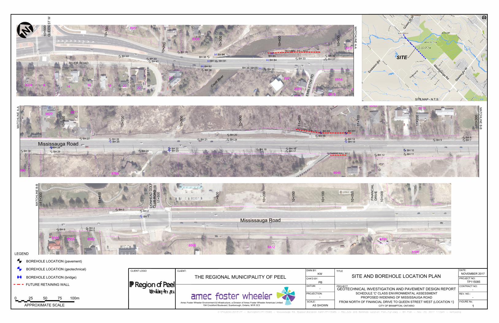
Mississauga Road
8586
8568 8562
8500
8472
8386
8394
10+
000
10+
050
10+
100
10+
150
10+
200
BH 2
BH 1
BH 3
BH 4
BH 5
BH 6
11+
300
11+
400
11+
500
11+
600
Mississauga Road
8827
8811
8846
8768
8646
8619
8649
BH 7
BH 8
BH 9
BH 10
BH 11
BH 12
BH 13
BH 15
BH 14
BH 16
BH 17
BH 18
BH 19
BH 20
BH 21
BH 22
BH 25
BH 23BH 24
BH 26
BH 27
BH 28
BH 29
BH 30
BH R2 BH R1
10+
600
10+
700
10+
800
10+
900
11+
000
11+
100
11+
200
11+
300
8951
8935
22
2018
16
14
9034 4
21
8837
8846
8854
2015
2014
2018
8921
BH 31
BH 32
BH 33
BH 37 / BH B1
BH 35
BH 36
BH 38
BH 39
BH 40
BH 41
BH 42
BH B2
BH 34 / BH B3
BH B4
BH B6
BH B5
10+
000
10+
100
1
0
+
2
0
0
10+
300
10+
400
10+
500
-
PROJECTION:
-
DATUM:
SITE AND BOREHOLE LOCATION PLAN
TITLE
PROJECT
CLIENT LOGO
FIGURE No.
THE REGIONAL MUNICIPALITY OF PEEL
REV. NO.:
1
PROJECT NO:
TP115085
-
CLIENT:
DWN BY:
CHK'D BY:
NOVEMBER 2017
DATE:
SCALE:
PB
AS SHOWN
KW
GEOTECHNICAL INVESTIGATION AND PAVEMENT DESIGN REPORT
SCHEDULE 'C' CLASS ENVIRONMENTAL ASSESSMENT
PROPOSED WIDENING OF MISSISSAUGA ROAD
FROM NORTH OF FINANCIAL DRIVE TO QUEEN STREET WEST (LOCATION 1)
CITY OF BRAMPTON, ONTARIO
CONTRACT NO:
-
Amec Foster Wheeler Environment & Infrastructure, a Division of Amec Foster Wheeler Americas Limited
104 Crockford Boulevard, Scarborough, Ontario, M1R 3C3
LEGEND
BOREHOLE LOCATION (pavement)
25 50 75 100m
APPROXIMATE SCALE
0
BOREHOLE LOCATION (geotechnical)
BOREHOLE LOCATION (bridge)
QU
EE
N S
T W
SITE MAP - N.T.S.
N
N
SITE
M
i
s
s
i
s
s
a
u
g
a
R
d
E
m
b
l
e
t
o
n
R
d
S
t
e
e
l
e
s
A
v
W
Q
u
e
e
n
S
t
W
F
i
n
a
n
c
i
a
l
D
r
FIN
AN
CIA
L
DR
IV
E
MA
TC
HLIN
E A
-A
MA
TC
HLIN
E B
-B
MA
TC
HLIN
E A
-A
MA
TC
HLIN
E B
-B
C
r
e
d
i
t
R
i
v
e
r
E
M
B
L
E
T
O
N
R
D
FUTURE RETAINING WALL
RETAINING WALL NO.3
R
E
T
A
IN
IN
G
W
A
LL N
O
.1
RETAINING WALL NO.2
LIO
NH
EA
D G
OL
F
CL
UB
R
OA
D
RIVER ROAD
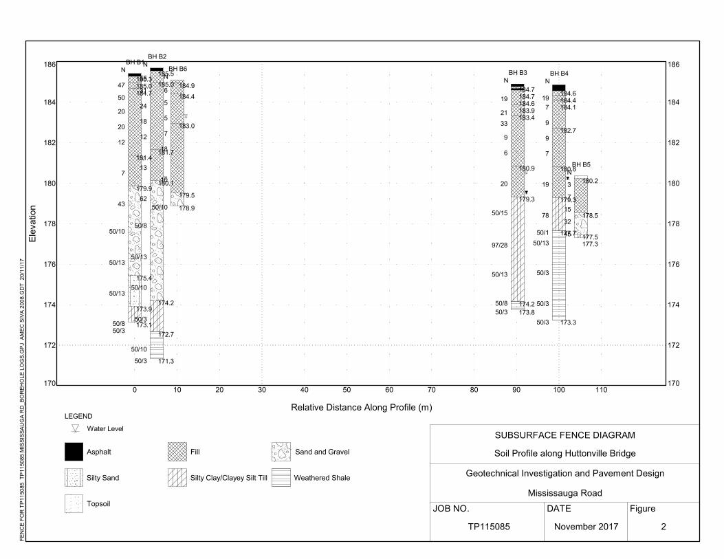
170
172
174
176
178
180
182
184
186
0 10 20 30 40 50 60 70 80 90 100 110170
172
174
176
178
180
182
184
186
185.3185.0184.7
181.4
179.9
175.4
173.9
173.1
47
50
20
20
12
7
43
50/10
50/13
50/13
50/850/3
NBH B1
185.5
185.0
181.7
180.1
174.2
172.7
171.3
55
31
24
18
12
13
62
50/8
50/13
50/10
50/3
50/10
50/3
NBH B2
184.7184.7184.6183.9183.4
180.9
179.3
174.2173.8
19
21
33
9
6
20
50/15
97/28
50/13
50/850/3
NBH B3
184.6184.4184.1
182.7
180.8
179.3
177.7
173.3
19
7
9
9
7
19
78
50/1
50/13
50/3
50/3
50/3
NBH B4
180.2
178.5
177.5177.3
3
7
15
32
45
NBH B5
184.9
184.4
183.0
179.5
178.9
6
5
5
7
18
10
50/10
NBH B6
Figure
Ele
vatio
n
LEGEND
Water Level
Asphalt Fill
Topsoil
SUBSURFACE FENCE DIAGRAM
Soil Profile along Huttonville Bridge
Geotechnical Investigation and Pavement Design
Mississauga Road
JOB NO. DATE
Relative Distance Along Profile (m)
FE
NC
E F
OR
TP
1150
85 T
P11
5085
MIS
SIS
SA
UG
A R
D_B
OR
EH
OLE
LO
GS
.GP
J A
ME
C S
IVA
200
8.G
DT
20
/11/
17
Silty Sand Silty Clay/Clayey Silt Till Weathered Shale
Sand and Gravel
TP115085 November 2017 2
RECORD OF BOREHOLES
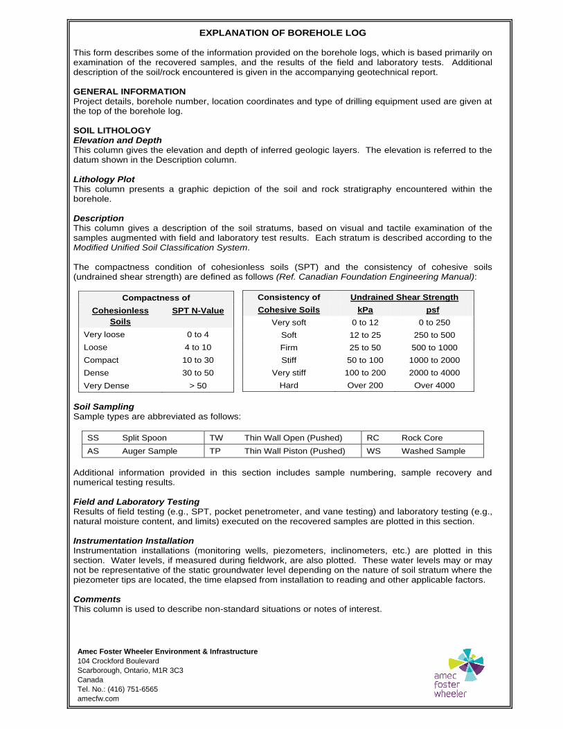
Amec Foster Wheeler Environment & Infrastructure
104 Crockford Boulevard
Scarborough, Ontario, M1R 3C3
Canada
Tel. No.: (416) 751-6565
amecfw.com
EXPLANATION OF BOREHOLE LOG This form describes some of the information provided on the borehole logs, which is based primarily on examination of the recovered samples, and the results of the field and laboratory tests. Additional description of the soil/rock encountered is given in the accompanying geotechnical report. GENERAL INFORMATION Project details, borehole number, location coordinates and type of drilling equipment used are given at the top of the borehole log. SOIL LITHOLOGY Elevation and Depth This column gives the elevation and depth of inferred geologic layers. The elevation is referred to the datum shown in the Description column. Lithology Plot This column presents a graphic depiction of the soil and rock stratigraphy encountered within the borehole. Description This column gives a description of the soil stratums, based on visual and tactile examination of the samples augmented with field and laboratory test results. Each stratum is described according to the Modified Unified Soil Classification System. The compactness condition of cohesionless soils (SPT) and the consistency of cohesive soils (undrained shear strength) are defined as follows (Ref. Canadian Foundation Engineering Manual):
Soil Sampling Sample types are abbreviated as follows:
SS Split Spoon TW Thin Wall Open (Pushed) RC Rock Core
AS Auger Sample TP Thin Wall Piston (Pushed) WS Washed Sample
Additional information provided in this section includes sample numbering, sample recovery and numerical testing results. Field and Laboratory Testing Results of field testing (e.g., SPT, pocket penetrometer, and vane testing) and laboratory testing (e.g., natural moisture content, and limits) executed on the recovered samples are plotted in this section. Instrumentation Installation Instrumentation installations (monitoring wells, piezometers, inclinometers, etc.) are plotted in this section. Water levels, if measured during fieldwork, are also plotted. These water levels may or may not be representative of the static groundwater level depending on the nature of soil stratum where the piezometer tips are located, the time elapsed from installation to reading and other applicable factors. Comments This column is used to describe non-standard situations or notes of interest.
Consistency of Undrained Shear Strength
Cohesive Soils kPa psf
Very soft 0 to 12 0 to 250
Soft 12 to 25 250 to 500
Firm 25 to 50 500 to 1000
Stiff 50 to 100 1000 to 2000
Very stiff 100 to 200 2000 to 4000
Hard Over 200 Over 4000
Compactness of
Cohesionless
Soils
SPT N-Value
Very loose 0 to 4
Loose 4 to 10
Compact 10 to 30
Dense 30 to 50
Very Dense > 50
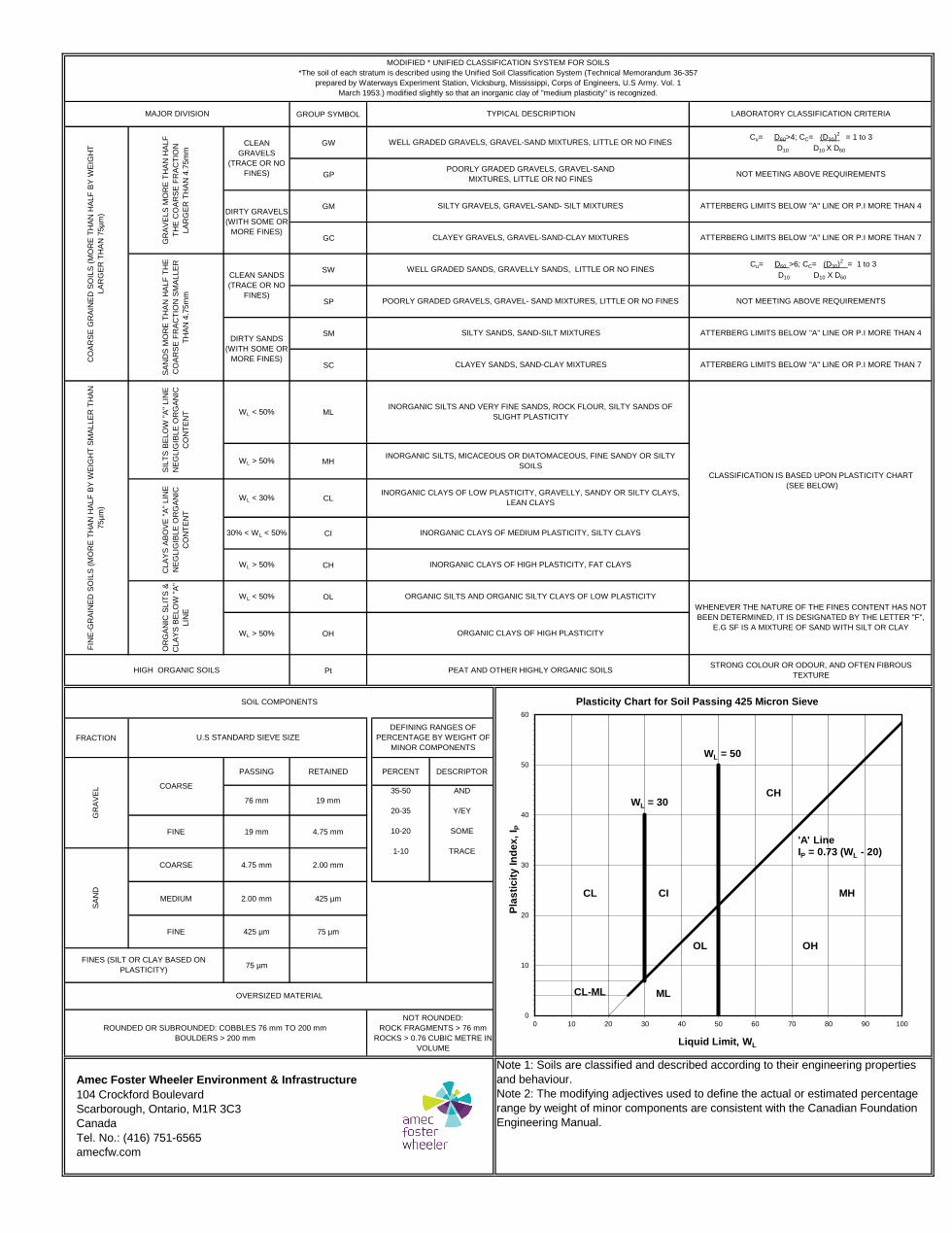
GROUP SYMBOL
GW
GP
GM
GC
SW
SP
SM
SC
WL < 50% ML
WL > 50% MH
WL < 30% CL
30% < WL < 50% CI
WL > 50% CH
WL < 50% OL
WL > 50% OH
Pt
FRACTION
PASSING RETAINED PERCENT DESCRIPTOR
76 mm 19 mm
FINE 19 mm 4.75 mm
COARSE 4.75 mm 2.00 mm
MEDIUM 2.00 mm 425 µm
FINE 425 µm 75 µm
75 µm
DEFINING RANGES OF
PERCENTAGE BY WEIGHT OF
MINOR COMPONENTS
U.S STANDARD SIEVE SIZE
35-50
20-35
10-20
1-10
SOIL COMPONENTS
MODIFIED * UNIFIED CLASSIFICATION SYSTEM FOR SOILS
*The soil of each stratum is described using the Unified Soil Classification System (Technical Memorandum 36-357
prepared by Waterways Experiment Station, Vicksburg, Mississippi, Corps of Engineers, U.S Army. Vol. 1
March 1953.) modified slightly so that an inorganic clay of "medium plasticity" is recognized.
MAJOR DIVISION TYPICAL DESCRIPTION LABORATORY CLASSIFICATION CRITERIA
CLA
YS
AB
OV
E "
A"
LIN
E
NE
GLIG
IBLE
OR
GA
NIC
CO
NT
EN
T
OR
GA
NIC
SLIT
S &
CLA
YS
BE
LO
W "
A"
LIN
E
CO
AR
SE
GR
AIN
ED
SO
ILS
(M
OR
E T
HA
N H
ALF
BY
WE
IGH
T
LA
RG
ER
TH
AN
75µ
m)
GR
AV
ELS
MO
RE
TH
AN
HA
LF
TH
E C
OA
RS
E F
RA
CT
ION
LA
RG
ER
TH
AN
4.7
5m
m
CLEAN
GRAVELS
(TRACE OR NO
FINES)
WELL GRADED GRAVELS, GRAVEL-SAND MIXTURES, LITTLE OR NO FINES
SA
ND
S M
OR
E T
HA
N H
ALF
TH
E
CO
AR
SE
FR
AC
TIO
N S
MA
LLE
R
TH
AN
4.7
5m
m
CLEAN SANDS
(TRACE OR NO
FINES)
WELL GRADED SANDS, GRAVELLY SANDS, LITTLE OR NO FINES
Cu= D60>4; CC= (D30)2
= 1 to 3
D10 D10 X D60
POORLY GRADED GRAVELS, GRAVEL-SAND
MIXTURES, LITTLE OR NO FINESNOT MEETING ABOVE REQUIREMENTS
DIRTY GRAVELS
(WITH SOME OR
MORE FINES)
SILTY GRAVELS, GRAVEL-SAND- SILT MIXTURES ATTERBERG LIMITS BELOW "A" LINE OR P.I MORE THAN 4
CLAYEY GRAVELS, GRAVEL-SAND-CLAY MIXTURES ATTERBERG LIMITS BELOW "A" LINE OR P.I MORE THAN 7
Cu= D60 >6; CC= (D30)2
= 1 to 3
D10 D10 X D60
POORLY GRADED GRAVELS, GRAVEL- SAND MIXTURES, LITTLE OR NO FINES NOT MEETING ABOVE REQUIREMENTS
DIRTY SANDS
(WITH SOME OR
MORE FINES)
SILTY SANDS, SAND-SILT MIXTURES ATTERBERG LIMITS BELOW "A" LINE OR P.I MORE THAN 4
CLAYEY SANDS, SAND-CLAY MIXTURES ATTERBERG LIMITS BELOW "A" LINE OR P.I MORE THAN 7
WHENEVER THE NATURE OF THE FINES CONTENT HAS NOT
BEEN DETERMINED, IT IS DESIGNATED BY THE LETTER "F",
E.G SF IS A MIXTURE OF SAND WITH SILT OR CLAYORGANIC CLAYS OF HIGH PLASTICITY
HIGH ORGANIC SOILS PEAT AND OTHER HIGHLY ORGANIC SOILSSTRONG COLOUR OR ODOUR, AND OFTEN FIBROUS
TEXTURE
FIN
E-G
RA
INE
D S
OIL
S (
MO
RE
TH
AN
HA
LF
BY
WE
IGH
T S
MA
LLE
R T
HA
N
75µ
m)
INORGANIC SILTS AND VERY FINE SANDS, ROCK FLOUR, SILTY SANDS OF
SLIGHT PLASTICITY
CLASSIFICATION IS BASED UPON PLASTICITY CHART
(SEE BELOW)
INORGANIC SILTS, MICACEOUS OR DIATOMACEOUS, FINE SANDY OR SILTY
SOILS
SIL
TS
BE
LO
W "
A"
LIN
E
NE
GLIG
IBLE
OR
GA
NIC
CO
NT
EN
T
INORGANIC CLAYS OF LOW PLASTICITY, GRAVELLY, SANDY OR SILTY CLAYS,
LEAN CLAYS
INORGANIC CLAYS OF MEDIUM PLASTICITY, SILTY CLAYS
INORGANIC CLAYS OF HIGH PLASTICITY, FAT CLAYS
ORGANIC SILTS AND ORGANIC SILTY CLAYS OF LOW PLASTICITY
Amec Foster Wheeler Environment & Infrastructure
104 Crockford Boulevard
Scarborough, Ontario, M1R 3C3
Canada
Tel. No.: (416) 751-6565
amecfw.com
GR
AV
EL COARSE
SA
ND
FINES (SILT OR CLAY BASED ON
PLASTICITY)
ROUNDED OR SUBROUNDED: COBBLES 76 mm TO 200 mm
BOULDERS > 200 mm
OVERSIZED MATERIAL
AND
Y/EY
SOME
TRACE
NOT ROUNDED:
ROCK FRAGMENTS > 76 mm
ROCKS > 0.76 CUBIC METRE IN
VOLUME
Note 1: Soils are classified and described according to their engineering properties
and behaviour.
Note 2: The modifying adjectives used to define the actual or estimated percentage
range by weight of minor components are consistent with the Canadian Foundation
Engineering Manual.
WL = 30
WL = 50
CH
CL CI MH
OL OH
CL-ML ML
0
10
20
30
40
50
60
0 10 20 30 40 50 60 70 80 90 100
Pla
sti
cit
y I
nd
ex
, I P
Liquid Limit, WL
Plasticity Chart for Soil Passing 425 Micron Sieve
'A' LineIP = 0.73 (WL - 20)
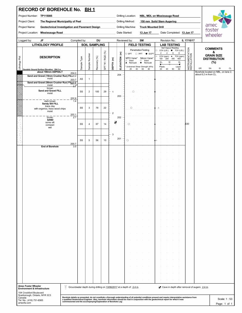
100
78
67
56
204.0
203.7
203.5
202.8
202.1
200.7
0.2
0.5
0.7
1.4
2.1
3.5
29
22
14
10
Borehole located on NBL, on lane 2,about 6.2 m from CL.
1
2
3
4
5
AS
SS
SS
SS
SS
about 190mm ASPHALT
Sand and Gravel (19mm Crusher Run) FILLmoist
Sand and Gravel (50mm Crusher Run) FILLmoistbrown
Sand and Gravel FILLmoist
dark brown Sandy Silt FILL
trace claywith organics, trace wood chips
moist
brown SAND
some siltcompact
wet
End of Borehole
Project Client:
Project Name:
Project Location:
Drilling Machine:
Drilling Method:
Drilling Location:Project Number: NBL, MDL on Mississauga Road
Reviewed by:Compiled by:Logged by:
TP115085
DU
Date Started:
Truck Mounted DrillGeotechnical Investigation and Pavement Design
Revision No.:
13 Jun 17
The Regional Municipality of Peel
Mississauga Road
0, 17/10/17SMJF
Date Completed: 13 Jun 17
150 mm Solid Stem Augering
SOIL SAMPLING
Sam
ple
Typ
e
Sam
ple
Num
ber
LITHOLOGY PROFILE FIELD TESTING
Rec
over
y (%
)
Lith
olog
y P
lot
LAB TESTINGCOMMENTS
&GRAIN SIZE
DISTRIBUTION(%)
SP
T 'N
' / R
QD
(%
)
Geodetic Ground Surface Elevation: 204.2 m
DCPT
* Undrained Shear Strength (kPa)
(m)
(m)
EL
EV
AT
IONDESCRIPTION
20 40 60 80
Intact
INS
TR
UM
EN
TA
TIO
NIN
ST
ALL
AT
ION
Remould
PenetrationTesting
SPT PPT
DE
PT
H RemouldIntact
Nilcon Vane*MTO Vane*
Liquid
WP
20 40 60 80
Soil Vapour Reading
W WL
TOV (ppm)100 200 300 400
2 4 6 8
COV (ppm)
COV (LEL) TOV (LEL)
PlasticCLSISAGR
104 Crockford BoulevardScarborough, Ontario, M1R 3C3CanadaTel. No.: (416) 751-6565amecfw.com
Amec Foster WheelerEnvironment & Infrastructure
Scale: 1 : 53Borehole details as presented, do not constitute a thorough understanding of all potential conditions present and require interpretative assistance froma qualified Geotechnical Engineer. Also, borehole information should be read in conjunction with the geotechnical report for which it wascommissioned and the accompanying'Explanation of Borehole Log'.
204
203
202
201
RECORD OF BOREHOLE No. BH 1
Page: 1 of 1
1
2
3
630
Groundwater depth during drilling on 13/06/2017 at a depth of: 2.4 m. Cave in depth after removal of augers: 2.4 m.
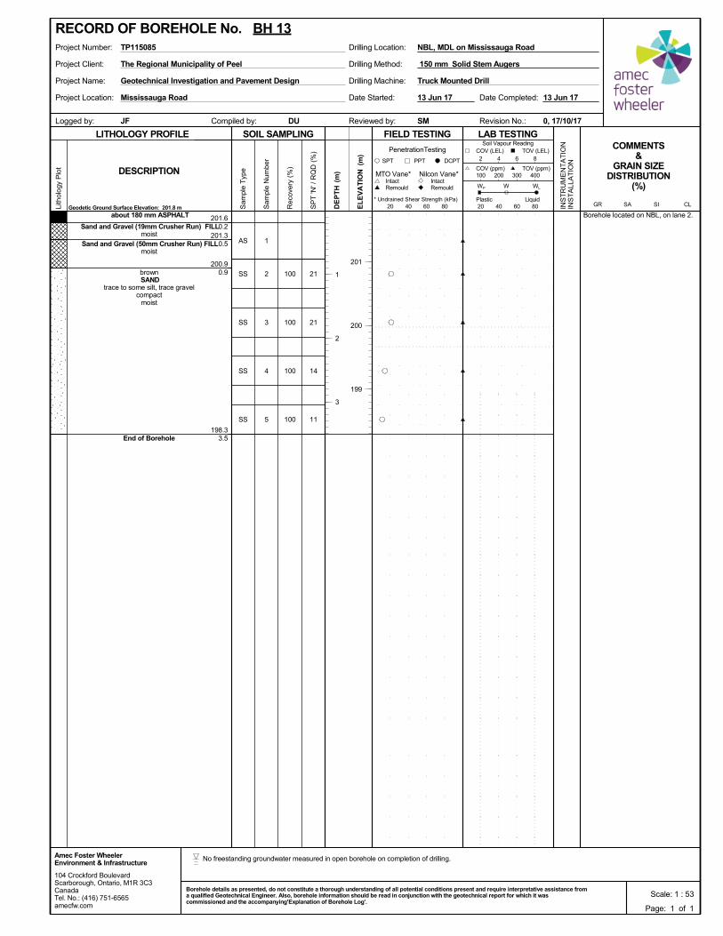
100
100
100
100
201.6
201.3
200.9
198.3
0.2
0.5
0.9
3.5
21
21
14
11
Borehole located on NBL, on lane 2.
1
2
3
4
5
AS
SS
SS
SS
SS
about 180 mm ASPHALT
Sand and Gravel (19mm Crusher Run) FILLmoist
Sand and Gravel (50mm Crusher Run) FILLmoist
brown SAND
trace to some silt, trace gravelcompact
moist
End of Borehole
Project Client:
Project Name:
Project Location:
Drilling Machine:
Drilling Method:
Drilling Location:Project Number: NBL, MDL on Mississauga Road
Reviewed by:Compiled by:Logged by:
TP115085
DU
Date Started:
Truck Mounted DrillGeotechnical Investigation and Pavement Design
Revision No.:
13 Jun 17
The Regional Municipality of Peel
Mississauga Road
0, 17/10/17SMJF
Date Completed: 13 Jun 17
150 mm Solid Stem Augers
SOIL SAMPLING
Sam
ple
Typ
e
Sam
ple
Num
ber
LITHOLOGY PROFILE FIELD TESTING
Rec
over
y (%
)
Lith
olog
y P
lot
LAB TESTINGCOMMENTS
&GRAIN SIZE
DISTRIBUTION(%)
SP
T 'N
' / R
QD
(%
)
Geodetic Ground Surface Elevation: 201.8 m
DCPT
* Undrained Shear Strength (kPa)
(m)
(m)
EL
EV
AT
IONDESCRIPTION
20 40 60 80
Intact
INS
TR
UM
EN
TA
TIO
NIN
ST
ALL
AT
ION
Remould
PenetrationTesting
SPT PPT
DE
PT
H RemouldIntact
Nilcon Vane*MTO Vane*
Liquid
WP
20 40 60 80
Soil Vapour Reading
W WL
TOV (ppm)100 200 300 400
2 4 6 8
COV (ppm)
COV (LEL) TOV (LEL)
PlasticCLSISAGR
104 Crockford BoulevardScarborough, Ontario, M1R 3C3CanadaTel. No.: (416) 751-6565amecfw.com
Amec Foster WheelerEnvironment & Infrastructure
Scale: 1 : 53Borehole details as presented, do not constitute a thorough understanding of all potential conditions present and require interpretative assistance froma qualified Geotechnical Engineer. Also, borehole information should be read in conjunction with the geotechnical report for which it wascommissioned and the accompanying'Explanation of Borehole Log'.
201
200
199
RECORD OF BOREHOLE No. BH 13
Page: 1 of 1
1
2
3
No freestanding groundwater measured in open borehole on completion of drilling.
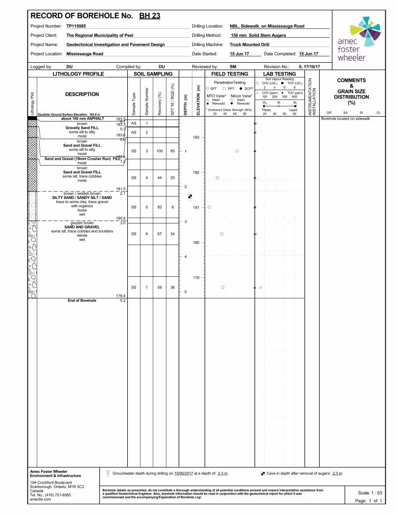
100
44
83
67
58
183.5
183.3
183.0
182.4
181.5
180.6
178.4
0.1
0.3
0.6
1.2
2.1
3.0
5.2
65
25
9
34
36
Borehole located on sidewalk.1
2
3
4
5
6
7
AS
AS
SS
SS
SS
SS
SS
about 100 mm ASPHALTbrown
Gravelly Sand FILLsome silt to silty
moistbrown
Sand and Gravel FILLsome silt to silty
moist Sand and Gravel (19mm Crusher Run) FILL
moistbrown
Sand and Gravel FILLsome silt, trace cobbles
moist
brown / reddish brownSILTY SAND / SANDY SILT / SAND
trace to some clay, trace gravelwith organics
loosewet
greyish brownSAND AND GRAVEL
some silt, trace cobbles and bouldersdense
wet
End of Borehole
Project Client:
Project Name:
Project Location:
Drilling Machine:
Drilling Method:
Drilling Location:Project Number: NBL, Sidewalk, on Mississauga Road
Reviewed by:Compiled by:Logged by:
TP115085
DU
Date Started:
Truck Mounted DrillGeotechnical Investigation and Pavement Design
Revision No.:
15 Jun 17
The Regional Municipality of Peel
Mississauga Road
0, 17/10/17SMDU
Date Completed: 15 Jun 17
150 mm Solid Stem Augers
SOIL SAMPLING
Sam
ple
Typ
e
Sam
ple
Num
ber
LITHOLOGY PROFILE FIELD TESTING
Rec
over
y (%
)
Lith
olog
y P
lot
LAB TESTINGCOMMENTS
&GRAIN SIZE
DISTRIBUTION(%)
SP
T 'N
' / R
QD
(%
)
Geodetic Ground Surface Elevation: 183.6 m
DCPT
* Undrained Shear Strength (kPa)
(m)
(m)
EL
EV
AT
IONDESCRIPTION
20 40 60 80
Intact
INS
TR
UM
EN
TA
TIO
NIN
ST
ALL
AT
ION
Remould
PenetrationTesting
SPT PPT
DE
PT
H RemouldIntact
Nilcon Vane*MTO Vane*
Liquid
WP
20 40 60 80
Soil Vapour Reading
W WL
TOV (ppm)100 200 300 400
2 4 6 8
COV (ppm)
COV (LEL) TOV (LEL)
PlasticCLSISAGR
104 Crockford BoulevardScarborough, Ontario, M1R 3C3CanadaTel. No.: (416) 751-6565amecfw.com
Amec Foster WheelerEnvironment & Infrastructure
Scale: 1 : 53Borehole details as presented, do not constitute a thorough understanding of all potential conditions present and require interpretative assistance froma qualified Geotechnical Engineer. Also, borehole information should be read in conjunction with the geotechnical report for which it wascommissioned and the accompanying'Explanation of Borehole Log'.
183
182
181
180
179
RECORD OF BOREHOLE No. BH 23
Page: 1 of 1
1
2
3
4
5
Groundwater depth during drilling on 15/06/2017 at a depth of: 2.3 m. Cave in depth after removal of augers: 2.3 m.
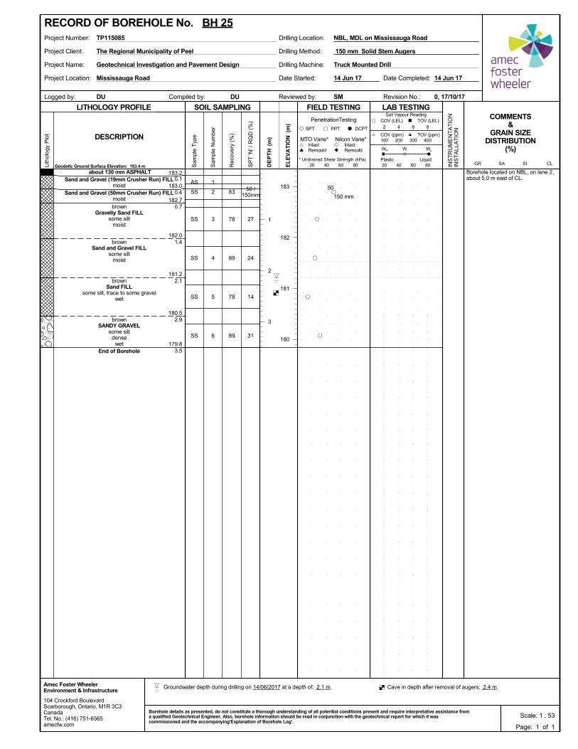
83
78
89
78
89
183.2
183.0
182.7
182.0
181.2
180.5
179.8
0.1
0.4
0.7
1.4
2.1
2.9
3.5
50 /150mm
27
24
14
31
Borehole located on NBL, on lane 2,about 5.0 m east of CL.
1
2
3
4
5
6
AS
SS
SS
SS
SS
SS
about 130 mm ASPHALTSand and Gravel (19mm Crusher Run) FILL
moistSand and Gravel (50mm Crusher Run) FILL
moist
brownGravelly Sand FILL
some siltmoist
brownSand and Gravel FILL
some siltmoist
brownSand FILL
some silt, trace to some gravelwet
brownSANDY GRAVEL
some siltdense
wetEnd of Borehole
Project Client:
Project Name:
Project Location:
Drilling Machine:
Drilling Method:
Drilling Location:Project Number: NBL, MDL on Mississauga Road
Reviewed by:Compiled by:Logged by:
TP115085
DU
Date Started:
Truck Mounted DrillGeotechnical Investigation and Pavement Design
Revision No.:
14 Jun 17
The Regional Municipality of Peel
Mississauga Road
0, 17/10/17SMDU
Date Completed: 14 Jun 17
150 mm Solid Stem Augers
SOIL SAMPLING
Sam
ple
Typ
e
Sam
ple
Num
ber
LITHOLOGY PROFILE FIELD TESTING
Rec
over
y (%
)
Lith
olog
y P
lot
LAB TESTINGCOMMENTS
&GRAIN SIZE
DISTRIBUTION(%)
SP
T 'N
' / R
QD
(%
)
Geodetic Ground Surface Elevation: 183.4 m
DCPT
* Undrained Shear Strength (kPa)
(m)
(m)
EL
EV
AT
IONDESCRIPTION
20 40 60 80
Intact
INS
TR
UM
EN
TA
TIO
NIN
ST
ALL
AT
ION
Remould
PenetrationTesting
SPT PPT
DE
PT
H RemouldIntact
Nilcon Vane*MTO Vane*
Liquid
WP
20 40 60 80
Soil Vapour Reading
W WL
TOV (ppm)100 200 300 400
2 4 6 8
COV (ppm)
COV (LEL) TOV (LEL)
PlasticCLSISAGR
104 Crockford BoulevardScarborough, Ontario, M1R 3C3CanadaTel. No.: (416) 751-6565amecfw.com
Amec Foster WheelerEnvironment & Infrastructure
Scale: 1 : 53Borehole details as presented, do not constitute a thorough understanding of all potential conditions present and require interpretative assistance froma qualified Geotechnical Engineer. Also, borehole information should be read in conjunction with the geotechnical report for which it wascommissioned and the accompanying'Explanation of Borehole Log'.
183
182
181
180
RECORD OF BOREHOLE No. BH 25
Page: 1 of 1
1
2
3
150 mm
50
Groundwater depth during drilling on 14/06/2017 at a depth of: 2.1 m. Cave in depth after removal of augers: 2.4 m.
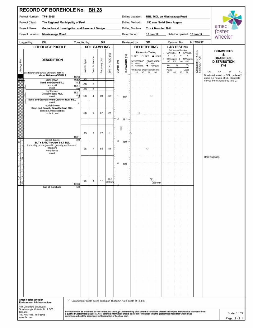
89
67
27
58
47
182.8182.7
182.4
182.1
180.1
178.0
0.20.3
0.6
0.9
2.9
5.0
67
27
1
54
70 /280mm
Borehole located on SBL, on lane 2,about 5.0 m west of CL. Boreholemoved from shoulder to lane 2.
Hard augering.
1
2
3
4
5
6
7
8
AS
AS
AS
SS
SS
SS
SS
SS
about 200 mm ASPHALT
dark brownSand and Gravel FILL
some siltmoist
light brownGravelly Sand FILL
moistSand and Gravel (19mm Crusher Run) FILL
moistreddish brown
Sand and Gravel / Gravelly Sand FILLsome silt, trace cobbles
moist to wet
greyish brownSILTY SAND / SANDY SILT TILL
trace clay, some gravel to gravelly, cobbles andboulders
very densemoist
End of Borehole
Project Client:
Project Name:
Project Location:
Drilling Machine:
Drilling Method:
Drilling Location:Project Number: NBL, MDL on Mississauga Road
Reviewed by:Compiled by:Logged by:
TP115085
DU
Date Started:
Truck Mounted DrillGeotechnical Investigation and Pavement Design
Revision No.:
15 Jun 17
The Regional Municipality of Peel
Mississauga Road
0, 17/10/17SMDU
Date Completed: 15 Jun 17
150 mm Solid Stem Augers
SOIL SAMPLING
Sam
ple
Typ
e
Sam
ple
Num
ber
LITHOLOGY PROFILE FIELD TESTING
Rec
over
y (%
)
Lith
olog
y P
lot
LAB TESTINGCOMMENTS
&GRAIN SIZE
DISTRIBUTION(%)
SP
T 'N
' / R
QD
(%
)
Geodetic Ground Surface Elevation: 183.0 m
DCPT
* Undrained Shear Strength (kPa)
(m)
(m)
EL
EV
AT
IONDESCRIPTION
20 40 60 80
Intact
INS
TR
UM
EN
TA
TIO
NIN
ST
ALL
AT
ION
Remould
PenetrationTesting
SPT PPT
DE
PT
H RemouldIntact
Nilcon Vane*MTO Vane*
Liquid
WP
20 40 60 80
Soil Vapour Reading
W WL
TOV (ppm)100 200 300 400
2 4 6 8
COV (ppm)
COV (LEL) TOV (LEL)
PlasticCLSISAGR
104 Crockford BoulevardScarborough, Ontario, M1R 3C3CanadaTel. No.: (416) 751-6565amecfw.com
Amec Foster WheelerEnvironment & Infrastructure
Scale: 1 : 53Borehole details as presented, do not constitute a thorough understanding of all potential conditions present and require interpretative assistance froma qualified Geotechnical Engineer. Also, borehole information should be read in conjunction with the geotechnical report for which it wascommissioned and the accompanying'Explanation of Borehole Log'.
182
181
180
179
RECORD OF BOREHOLE No. BH 28
Page: 1 of 1
1
2
3
4
5280 mm
70
Groundwater depth during drilling on 15/06/2017 at a depth of: 2.4 m.
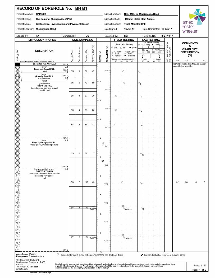
58
42
83
89
89
89
100
100
100
50 15 3
185.3
185.0
184.7
181.4
179.9
175.4
0.2
0.5
0.7
4.0
5.6
32
47
50
20
20
12
7
43
50 /100mm
50 /130mm
Borehole located on NBL, on lane 2,about 6.5 m from CL.
1
2
3
4
5
6
7
8
9
SS
SS
SS
SS
SS
SS
SS
SS
SS
about 160 mm ASPHALT
brownSand and Gravel FILL
moistbrown
Gravelly Sand FILLtrace cobbles
moistgrey / brown
Silty Sand FILLtrace to some clay and gravel
moist to wet
brownSilty Clay / Clayey Silt FILL
trace gravel, with sand pockets
brown / reddish brown GRAVELLY SAND
trace clay, some silt, trace cobblesdense to very dense
wet
Project Client:
Project Name:
Project Location:
Drilling Machine:
Drilling Method:
Drilling Location:Project Number: NBL, MDL on Mississauga Road
Reviewed by:Compiled by:Logged by:
TP115085
DU
Date Started:
Truck Mounted DrillGeotechnical Investigation and Pavement Design
Revision No.:
16 Jun 17
The Regional Municipality of Peel
Mississauga Road
0, 27/10/17SMKK
Date Completed: 16 Jun 17
150 mm Solid Stem Augers
SOIL SAMPLING
Sam
ple
Typ
e
Sam
ple
Num
ber
LITHOLOGY PROFILE FIELD TESTING
Rec
over
y (%
)
Lith
olog
y P
lot
LAB TESTINGCOMMENTS
&GRAIN SIZE
DISTRIBUTION(%)
SP
T 'N
' / R
QD
(%
)
Geodetic Ground Surface Elevation: 185.4 m
DCPT
* Undrained Shear Strength (kPa)
(m)
(m)
EL
EV
AT
IONDESCRIPTION
20 40 60 80
Intact
INS
TR
UM
EN
TA
TIO
NIN
ST
ALL
AT
ION
Remould
PenetrationTesting
SPT PPT
DE
PT
H RemouldIntact
Nilcon Vane*MTO Vane*
Liquid
WP
20 40 60 80
Soil Vapour Reading
W WL
TOV (ppm)100 200 300 400
2 4 6 8
COV (ppm)
COV (LEL) TOV (LEL)
PlasticCLSISAGR
104 Crockford BoulevardScarborough, Ontario, M1R 3C3CanadaTel. No.: (416) 751-6565amecfw.com
Amec Foster WheelerEnvironment & Infrastructure
Scale: 1 : 53Borehole details as presented, do not constitute a thorough understanding of all potential conditions present and require interpretative assistance froma qualified Geotechnical Engineer. Also, borehole information should be read in conjunction with the geotechnical report for which it wascommissioned and the accompanying'Explanation of Borehole Log'.
Continued on Next Page
185
184
183
182
181
180
179
178
177
176
RECORD OF BOREHOLE No. BH B1
Page: 1 of 2
1
2
3
4
5
6
7
8
9
10
4
6
11
9
11
13
11
15
11
100 mm
50
130 mm
50
Groundwater depth during drilling on 17/06/2017 at a depth of: 4.3 m. Cave in depth after removal of augers: 5.2 m.
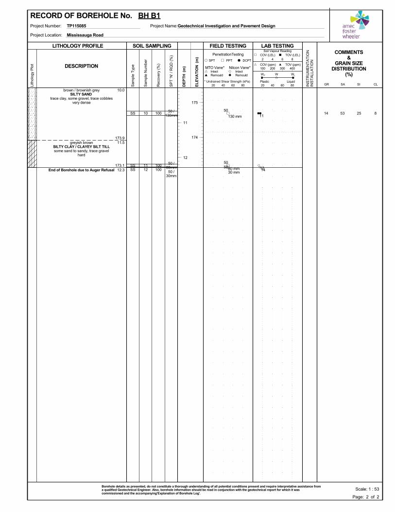
100
100100
53 25 8
173.9
173.1
10.0
11.5
12.3
1450 /130mm
50 /80mm50 /
30mm
10
1112
SS
SSSS
brown / brownish greySILTY SAND
trace clay, some gravel, trace cobblesvery dense
greyish brownSILTY CLAY / CLAYEY SILT TILLsome sand to sandy, trace gravel
hard
End of Borehole due to Auger Refusal
SOIL SAMPLING
Sam
ple
Typ
e
Sam
ple
Num
ber
LITHOLOGY PROFILE FIELD TESTING
Rec
over
y (%
)
Lith
olog
y P
lot
LAB TESTINGCOMMENTS
&GRAIN SIZE
DISTRIBUTION(%)
SP
T 'N
' / R
QD
(%
)
DCPT
* Undrained Shear Strength (kPa)
(m)
(m)
EL
EV
AT
IONDESCRIPTION
20 40 60 80
Intact
INS
TR
UM
EN
TA
TIO
NIN
ST
ALL
AT
ION
Remould
PenetrationTesting
SPT PPT
DE
PT
H RemouldIntact
Nilcon Vane*MTO Vane*
Liquid
WP
20 40 60 80
Soil Vapour Reading
W WL
TOV (ppm)100 200 300 400
2 4 6 8
COV (ppm)
COV (LEL) TOV (LEL)
PlasticCLSISAGR
Project Location:
Project Number: Project Name:TP115085
Mississauga Road
Geotechnical Investigation and Pavement Design
Scale: 1 : 53Borehole details as presented, do not constitute a thorough understanding of all potential conditions present and require interpretative assistance froma qualified Geotechnical Engineer. Also, borehole information should be read in conjunction with the geotechnical report for which it wascommissioned and the accompanying'Explanation of Borehole Log'.
175
174
RECORD OF BOREHOLE No. BH B1
Page: 2 of 2
11
12
11
1214
130 mm
50
80 mm
50
30 mm50
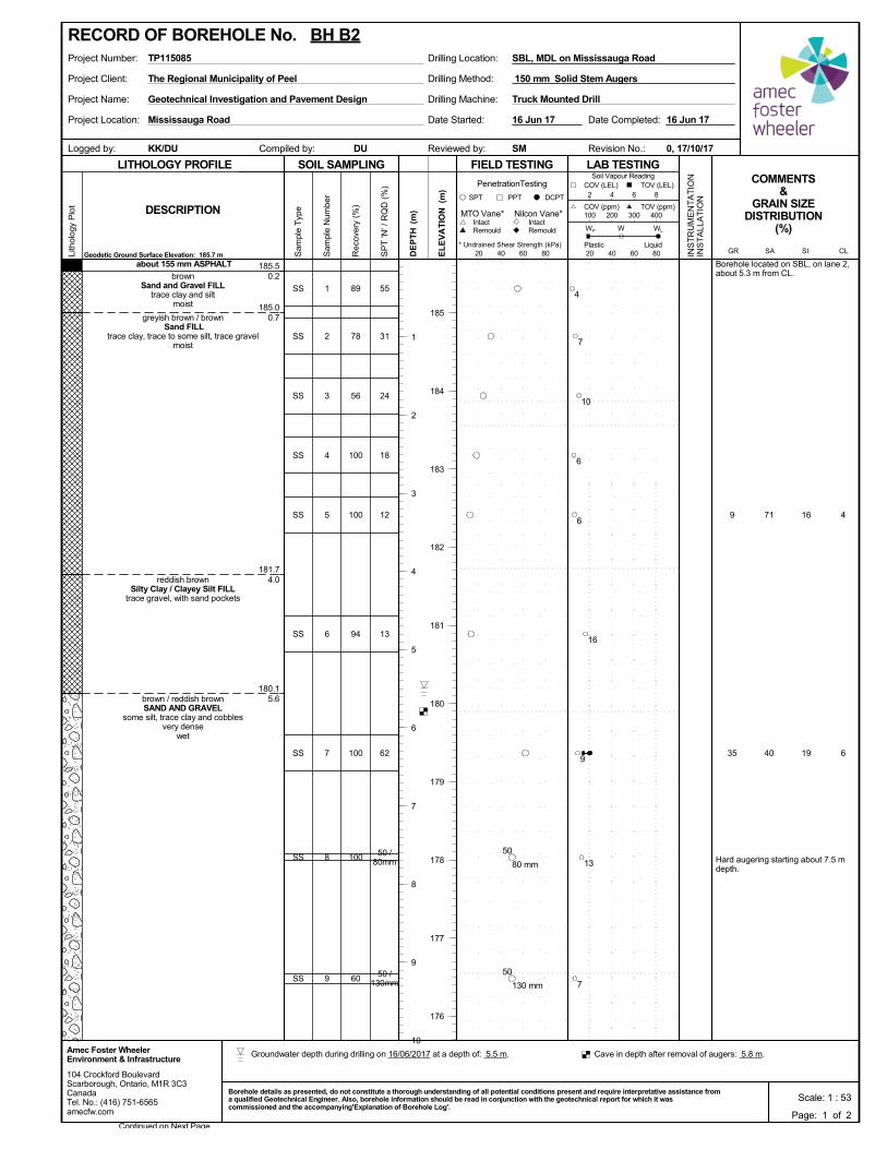
89
78
56
100
100
94
100
100
60
71
40
16
19
4
6
185.5
185.0
181.7
180.1
0.2
0.7
4.0
5.6
9
35
55
31
24
18
12
13
62
50 /80mm
50 /130mm
Borehole located on SBL, on lane 2,about 5.3 m from CL.
Hard augering starting about 7.5 mdepth.
1
2
3
4
5
6
7
8
9
SS
SS
SS
SS
SS
SS
SS
SS
SS
about 155 mm ASPHALT
brownSand and Gravel FILL
trace clay and siltmoist
greyish brown / brown Sand FILL
trace clay, trace to some silt, trace gravelmoist
reddish brownSilty Clay / Clayey Silt FILL
trace gravel, with sand pockets
brown / reddish brownSAND AND GRAVEL
some silt, trace clay and cobblesvery dense
wet
Project Client:
Project Name:
Project Location:
Drilling Machine:
Drilling Method:
Drilling Location:Project Number: SBL, MDL on Mississauga Road
Reviewed by:Compiled by:Logged by:
TP115085
DU
Date Started:
Truck Mounted DrillGeotechnical Investigation and Pavement Design
Revision No.:
16 Jun 17
The Regional Municipality of Peel
Mississauga Road
0, 17/10/17SMKK/DU
Date Completed: 16 Jun 17
150 mm Solid Stem Augers
SOIL SAMPLING
Sam
ple
Typ
e
Sam
ple
Num
ber
LITHOLOGY PROFILE FIELD TESTING
Rec
over
y (%
)
Lith
olog
y P
lot
LAB TESTINGCOMMENTS
&GRAIN SIZE
DISTRIBUTION(%)
SP
T 'N
' / R
QD
(%
)
Geodetic Ground Surface Elevation: 185.7 m
DCPT
* Undrained Shear Strength (kPa)
(m)
(m)
EL
EV
AT
IONDESCRIPTION
20 40 60 80
Intact
INS
TR
UM
EN
TA
TIO
NIN
ST
ALL
AT
ION
Remould
PenetrationTesting
SPT PPT
DE
PT
H RemouldIntact
Nilcon Vane*MTO Vane*
Liquid
WP
20 40 60 80
Soil Vapour Reading
W WL
TOV (ppm)100 200 300 400
2 4 6 8
COV (ppm)
COV (LEL) TOV (LEL)
PlasticCLSISAGR
104 Crockford BoulevardScarborough, Ontario, M1R 3C3CanadaTel. No.: (416) 751-6565amecfw.com
Amec Foster WheelerEnvironment & Infrastructure
Scale: 1 : 53Borehole details as presented, do not constitute a thorough understanding of all potential conditions present and require interpretative assistance froma qualified Geotechnical Engineer. Also, borehole information should be read in conjunction with the geotechnical report for which it wascommissioned and the accompanying'Explanation of Borehole Log'.
Continued on Next Page
185
184
183
182
181
180
179
178
177
176
RECORD OF BOREHOLE No. BH B2
Page: 1 of 2
1
2
3
4
5
6
7
8
9
10
4
7
10
6
6
16
9
13
7
80 mm
50
130 mm
50
Groundwater depth during drilling on 16/06/2017 at a depth of: 5.5 m. Cave in depth after removal of augers: 5.8 m.
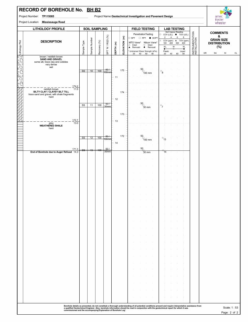
100
100
100
100
174.2
172.7
171.3
11.5
13.0
14.3
50 /100mm
50 /30mm
50 /100mm
50 /30mm
10
11
12
13
SS
SS
SS
SS
brown / reddish brownSAND AND GRAVEL
some silt, trace clay and cobblesvery dense
wet
reddish brownSILTY CLAY / CLAYEY SILT TILL
trace sand and gravel, with shale fragmentshard
greyWEATHERED SHALE
hard
End of Borehole due to Auger Refusal
SOIL SAMPLING
Sam
ple
Typ
e
Sam
ple
Num
ber
LITHOLOGY PROFILE FIELD TESTING
Rec
over
y (%
)
Lith
olog
y P
lot
LAB TESTINGCOMMENTS
&GRAIN SIZE
DISTRIBUTION(%)
SP
T 'N
' / R
QD
(%
)
DCPT
* Undrained Shear Strength (kPa)
(m)
(m)
EL
EV
AT
IONDESCRIPTION
20 40 60 80
Intact
INS
TR
UM
EN
TA
TIO
NIN
ST
ALL
AT
ION
Remould
PenetrationTesting
SPT PPT
DE
PT
H RemouldIntact
Nilcon Vane*MTO Vane*
Liquid
WP
20 40 60 80
Soil Vapour Reading
W WL
TOV (ppm)100 200 300 400
2 4 6 8
COV (ppm)
COV (LEL) TOV (LEL)
PlasticCLSISAGR
Project Location:
Project Number: Project Name:TP115085
Mississauga Road
Geotechnical Investigation and Pavement Design
Scale: 1 : 53Borehole details as presented, do not constitute a thorough understanding of all potential conditions present and require interpretative assistance froma qualified Geotechnical Engineer. Also, borehole information should be read in conjunction with the geotechnical report for which it wascommissioned and the accompanying'Explanation of Borehole Log'.
175
174
173
172
RECORD OF BOREHOLE No. BH B2
Page: 2 of 2
11
12
13
14
8
7
13
14
100 mm
50
30 mm
50
100 mm
50
30 mm
50
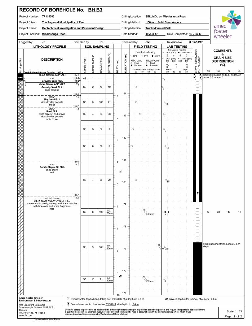
79
100
83
67
56
56
100
106
91
39 43 12
184.7184.7184.6
183.9
183.4
180.9
179.3
0.20.20.3
1.0
1.5
4.0
5.6
6
19
21
33
9
6
20
50 /150mm
97 /280mm
50 /130mm
Borehole located on SBL, on lane 2,about 5.3 m from CL.
Hard augering starting about 7.5 mdepth.
1
2
3
4
5
6
7
8
9
10
AS
SS
SS
SS
SS
SS
SS
SS
SS
SS
about 150 mm ASPHALT
brown Gravelly Sand FILL
about 90 mm ASPHALTGravelly Sand FILL
trace cobbles
brownSilty Sand FILL
with silty clay pocketsmoist
brownSand FILL
trace clay, silt and gravelwith silty clay pockets
moist to wet
brownSandy Clayey Silt FILL
trace gravelwet
reddish brownSILTY CLAY / CLAYEY SILT TILL
some sand to sandy, trace gravel, trace cobbleswith limestone and shale fragments
hard
Project Client:
Project Name:
Project Location:
Drilling Machine:
Drilling Method:
Drilling Location:Project Number: SBL, MDL on Mississauga Road
Reviewed by:Compiled by:Logged by:
TP115085
DU
Date Started:
Truck Mounted DrillGeotechnical Investigation and Pavement Design
Revision No.:
19 Jun 17
The Regional Municipality of Peel
Mississauga Road
0, 17/10/17SMJF
Date Completed: 19 Jun 17
150 mm Solid Stem Augers
SOIL SAMPLING
Sam
ple
Typ
e
Sam
ple
Num
ber
LITHOLOGY PROFILE FIELD TESTING
Rec
over
y (%
)
Lith
olog
y P
lot
LAB TESTINGCOMMENTS
&GRAIN SIZE
DISTRIBUTION(%)
SP
T 'N
' / R
QD
(%
)
Geodetic Ground Surface Elevation: 184.9 m
DCPT
* Undrained Shear Strength (kPa)
(m)
(m)
EL
EV
AT
IONDESCRIPTION
20 40 60 80
Intact
INS
TR
UM
EN
TA
TIO
NIN
ST
ALL
AT
ION
Remould
PenetrationTesting
SPT PPT
DE
PT
H RemouldIntact
Nilcon Vane*MTO Vane*
Liquid
WP
20 40 60 80
Soil Vapour Reading
W WL
TOV (ppm)100 200 300 400
2 4 6 8
COV (ppm)
COV (LEL) TOV (LEL)
PlasticCLSISAGR
104 Crockford BoulevardScarborough, Ontario, M1R 3C3CanadaTel. No.: (416) 751-6565amecfw.com
Amec Foster WheelerEnvironment & Infrastructure
Scale: 1 : 53Borehole details as presented, do not constitute a thorough understanding of all potential conditions present and require interpretative assistance froma qualified Geotechnical Engineer. Also, borehole information should be read in conjunction with the geotechnical report for which it wascommissioned and the accompanying'Explanation of Borehole Log'.
Continued on Next Page
184
183
182
181
180
179
178
177
176
175
RECORD OF BOREHOLE No. BH B3
Page: 1 of 2
1
2
3
4
5
6
7
8
9
10
5
3
11
7
9
13
15
9
11
8
150 mm
50
280 mm
97
130 mm
50
Groundwater depth during drilling on 19/06/2017 at a depth of: 4.4 m. Cave in depth after removal of augers: 9.1 m.
Groundwater depth observed on 2/10/2017 at a depth of: 5.4 m.
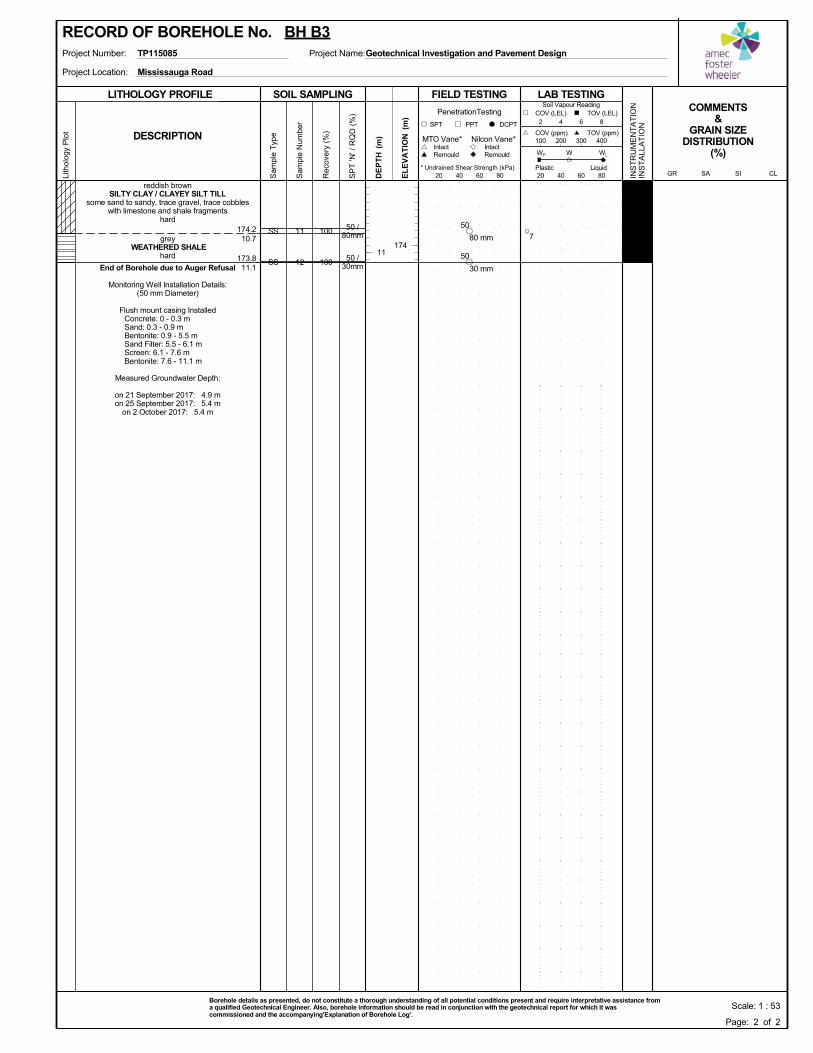
100
100
174.2
173.8
10.7
11.1
50 /80mm
50 /30mm
11
12
SS
SS
reddish brownSILTY CLAY / CLAYEY SILT TILL
some sand to sandy, trace gravel, trace cobbleswith limestone and shale fragments
hard
grey WEATHERED SHALE
hard
End of Borehole due to Auger Refusal
Monitoring Well Installation Details:(50 mm Diameter)
Flush mount casing Installed Concrete: 0 - 0.3 m Sand: 0.3 - 0.9 m Bentonite: 0.9 - 5.5 m Sand Filter: 5.5 - 6.1 m Screen: 6.1 - 7.6 m Bentonite: 7.6 - 11.1 m
Measured Groundwater Depth:
on 21 September 2017: 4.9 mon 25 September 2017: 5.4 m
on 2 October 2017: 5.4 m
SOIL SAMPLING
Sam
ple
Typ
e
Sam
ple
Num
ber
LITHOLOGY PROFILE FIELD TESTING
Rec
over
y (%
)
Lith
olog
y P
lot
LAB TESTINGCOMMENTS
&GRAIN SIZE
DISTRIBUTION(%)
SP
T 'N
' / R
QD
(%
)
DCPT
* Undrained Shear Strength (kPa)
(m)
(m)
EL
EV
AT
IONDESCRIPTION
20 40 60 80
Intact
INS
TR
UM
EN
TA
TIO
NIN
ST
ALL
AT
ION
Remould
PenetrationTesting
SPT PPT
DE
PT
H RemouldIntact
Nilcon Vane*MTO Vane*
Liquid
WP
20 40 60 80
Soil Vapour Reading
W WL
TOV (ppm)100 200 300 400
2 4 6 8
COV (ppm)
COV (LEL) TOV (LEL)
PlasticCLSISAGR
Project Location:
Project Number: Project Name:TP115085
Mississauga Road
Geotechnical Investigation and Pavement Design
Scale: 1 : 53Borehole details as presented, do not constitute a thorough understanding of all potential conditions present and require interpretative assistance froma qualified Geotechnical Engineer. Also, borehole information should be read in conjunction with the geotechnical report for which it wascommissioned and the accompanying'Explanation of Borehole Log'.
174
RECORD OF BOREHOLE No. BH B3
Page: 2 of 2
11
780 mm
50
30 mm
50
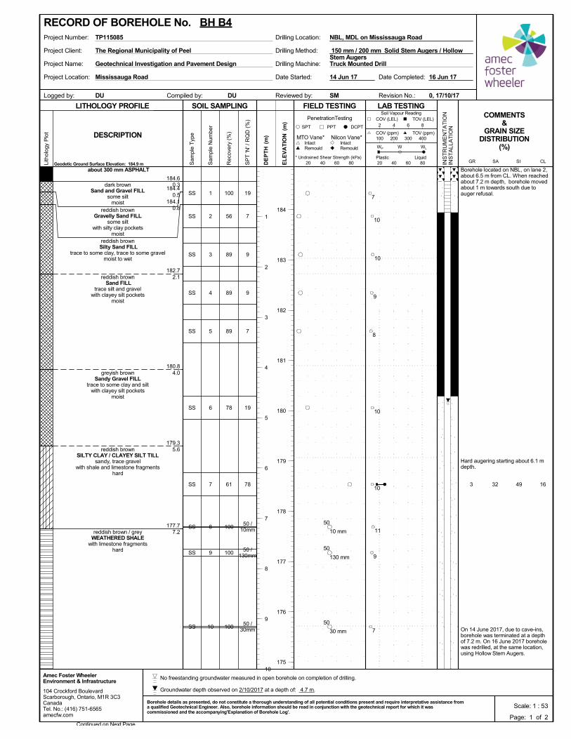
100
56
89
89
89
78
61
100
100
100
32 49 16
184.6
184.4
184.1
182.7
180.8
179.3
177.7
0.3
0.5
0.8
2.1
4.0
5.6
7.2
3
19
7
9
9
7
19
78
50 /10mm
50 /130mm
50 /30mm
Borehole located on NBL, on lane 2,about 6.5 m from CL. When reachedabout 7.2 m depth, borehole movedabout 1 m towards south due toauger refusal.
Hard augering starting about 6.1 mdepth.
On 14 June 2017, due to cave-ins,borehole was terminated at a depthof 7.2 m. On 16 June 2017 boreholewas redrilled, at the same location,using Hollow Stem Augers.
1
2
3
4
5
6
7
8
9
10
SS
SS
SS
SS
SS
SS
SS
SS
SS
SS
about 300 mm ASPHALT
dark brownSand and Gravel FILL
some siltmoist
reddish brownGravelly Sand FILL
some siltwith silty clay pockets
moistreddish brownSilty Sand FILL
trace to some clay, trace to some gravelmoist to wet
reddish brown Sand FILL
trace silt and gravelwith clayey silt pockets
moist
greyish brownSandy Gravel FILL
trace to some clay and siltwith clayey silt pockets
moist
reddish brownSILTY CLAY / CLAYEY SILT TILL
sandy, trace gravelwith shale and limestone fragments
hard
reddish brown / greyWEATHERED SHALE
with limestone fragmentshard
Project Client:
Project Name:
Project Location:
Drilling Machine:
Drilling Method:
Drilling Location:Project Number: NBL, MDL on Mississauga Road
Reviewed by:Compiled by:Logged by:
TP115085
DU
Date Started:
Truck Mounted DrillGeotechnical Investigation and Pavement Design
Revision No.:
14 Jun 17
The Regional Municipality of Peel
Mississauga Road
0, 17/10/17SMDU
Date Completed: 16 Jun 17
150 mm / 200 mm Solid Stem Augers / HollowStem Augers
SOIL SAMPLING
Sam
ple
Typ
e
Sam
ple
Num
ber
LITHOLOGY PROFILE FIELD TESTING
Rec
over
y (%
)
Lith
olog
y P
lot
LAB TESTINGCOMMENTS
&GRAIN SIZE
DISTRIBUTION(%)
SP
T 'N
' / R
QD
(%
)
Geodetic Ground Surface Elevation: 184.9 m
DCPT
* Undrained Shear Strength (kPa)
(m)
(m)
EL
EV
AT
IONDESCRIPTION
20 40 60 80
Intact
INS
TR
UM
EN
TA
TIO
NIN
ST
ALL
AT
ION
Remould
PenetrationTesting
SPT PPT
DE
PT
H RemouldIntact
Nilcon Vane*MTO Vane*
Liquid
WP
20 40 60 80
Soil Vapour Reading
W WL
TOV (ppm)100 200 300 400
2 4 6 8
COV (ppm)
COV (LEL) TOV (LEL)
PlasticCLSISAGR
104 Crockford BoulevardScarborough, Ontario, M1R 3C3CanadaTel. No.: (416) 751-6565amecfw.com
Amec Foster WheelerEnvironment & Infrastructure
Scale: 1 : 53Borehole details as presented, do not constitute a thorough understanding of all potential conditions present and require interpretative assistance froma qualified Geotechnical Engineer. Also, borehole information should be read in conjunction with the geotechnical report for which it wascommissioned and the accompanying'Explanation of Borehole Log'.
Continued on Next Page
184
183
182
181
180
179
178
177
176
175
RECORD OF BOREHOLE No. BH B4
Page: 1 of 2
1
2
3
4
5
6
7
8
9
10
7
10
10
9
8
10
10
11
9
7
10 mm
50
130 mm
50
30 mm
50
No freestanding groundwater measured in open borehole on completion of drilling.
Groundwater depth observed on 2/10/2017 at a depth of: 4.7 m.
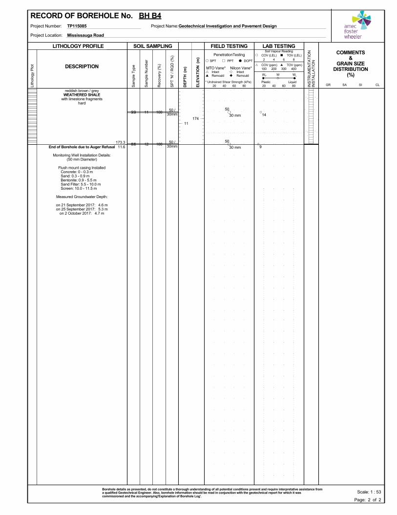
100
100173.311.6
50 /30mm
50 /30mm
11
12
SS
SS
reddish brown / greyWEATHERED SHALE
with limestone fragmentshard
End of Borehole due to Auger Refusal
Monitoring Well Installation Details:(50 mm Diameter)
Flush mount casing Installed Concrete: 0 - 0.3 m Sand: 0.3 - 0.9 m Bentonite: 0.9 - 5.5 m Sand Filter: 5.5 - 10.0 m Screen: 10.0 - 11.5 m
Measured Groundwater Depth:
on 21 September 2017: 4.6 mon 25 September 2017: 5.3 m
on 2 October 2017: 4.7 m
SOIL SAMPLING
Sam
ple
Typ
e
Sam
ple
Num
ber
LITHOLOGY PROFILE FIELD TESTING
Rec
over
y (%
)
Lith
olog
y P
lot
LAB TESTINGCOMMENTS
&GRAIN SIZE
DISTRIBUTION(%)
SP
T 'N
' / R
QD
(%
)
DCPT
* Undrained Shear Strength (kPa)
(m)
(m)
EL
EV
AT
IONDESCRIPTION
20 40 60 80
Intact
INS
TR
UM
EN
TA
TIO
NIN
ST
ALL
AT
ION
Remould
PenetrationTesting
SPT PPT
DE
PT
H RemouldIntact
Nilcon Vane*MTO Vane*
Liquid
WP
20 40 60 80
Soil Vapour Reading
W WL
TOV (ppm)100 200 300 400
2 4 6 8
COV (ppm)
COV (LEL) TOV (LEL)
PlasticCLSISAGR
Project Location:
Project Number: Project Name:TP115085
Mississauga Road
Geotechnical Investigation and Pavement Design
Scale: 1 : 53Borehole details as presented, do not constitute a thorough understanding of all potential conditions present and require interpretative assistance froma qualified Geotechnical Engineer. Also, borehole information should be read in conjunction with the geotechnical report for which it wascommissioned and the accompanying'Explanation of Borehole Log'.
174
RECORD OF BOREHOLE No. BH B4
Page: 2 of 2
11
14
9
30 mm
50
30 mm
50
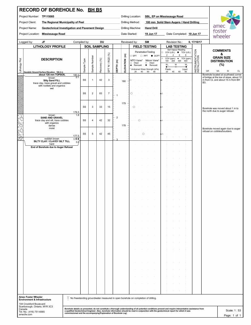
42
83
33
42
42
180.2
178.5
177.5
177.3
0.1
1.8
2.93.0
3
7
15
32
45
Borehole located at southwest cornerof bridge at the toe of slope, about 10m from CL and about 15 m from BHB3.
Borehole was moved about 1 m tothe north due to auger refusal.
Borehole moved again due to augerrefusal on cobbles/boulders.
1
2
3
4
5
SS
SS
SS
SS
SS
about 120 mm TOPSOILbrown
Silty Sand FILLtrace clay, trace gravel and cobbles
with rootlets and organicswet
brownSAND AND GRAVEL
trace clay and silt, trace cobbleswith organics
densemoist
reddish brownSILTY CLAY / CLAYEY SILT TILL
hardEnd of Borehole due to Auger Refusal
Project Client:
Project Name:
Project Location:
Drilling Machine:
Drilling Method:
Drilling Location:Project Number: SBL, EP on Mississauga Road
Reviewed by:Compiled by:Logged by:
TP115085
DU
Date Started:
Hand DrillGeotechnical Investigation and Pavement Design
Revision No.:
19 Jun 17
The Regional Municipality of Peel
Mississauga Road
0, 17/10/17SMJF
Date Completed: 19 Jun 17
100 mm Solid Stem Augers / Hand Drilling
SOIL SAMPLING
Sam
ple
Typ
e
Sam
ple
Num
ber
LITHOLOGY PROFILE FIELD TESTING
Rec
over
y (%
)
Lith
olog
y P
lot
LAB TESTINGCOMMENTS
&GRAIN SIZE
DISTRIBUTION(%)
SP
T 'N
' / R
QD
(%
)
Geodetic Ground Surface Elevation: 180.4 m
DCPT
* Undrained Shear Strength (kPa)
(m)
(m)
EL
EV
AT
IONDESCRIPTION
20 40 60 80
Intact
INS
TR
UM
EN
TA
TIO
NIN
ST
ALL
AT
ION
Remould
PenetrationTesting
SPT PPT
DE
PT
H RemouldIntact
Nilcon Vane*MTO Vane*
Liquid
WP
20 40 60 80
Soil Vapour Reading
W WL
TOV (ppm)100 200 300 400
2 4 6 8
COV (ppm)
COV (LEL) TOV (LEL)
PlasticCLSISAGR
104 Crockford BoulevardScarborough, Ontario, M1R 3C3CanadaTel. No.: (416) 751-6565amecfw.com
Amec Foster WheelerEnvironment & Infrastructure
Scale: 1 : 53Borehole details as presented, do not constitute a thorough understanding of all potential conditions present and require interpretative assistance froma qualified Geotechnical Engineer. Also, borehole information should be read in conjunction with the geotechnical report for which it wascommissioned and the accompanying'Explanation of Borehole Log'.
180
179
178
RECORD OF BOREHOLE No. BH B5
Page: 1 of 1
1
2
3
No freestanding groundwater measured in open borehole on completion of drilling.
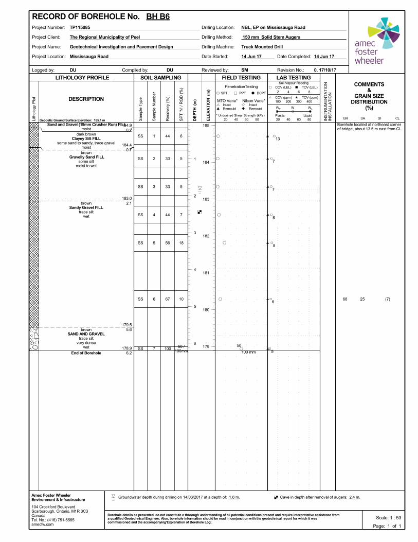
44
33
33
44
56
67
100
25 (7)
184.9
184.4
183.0
179.5
178.9
0.2
0.7
2.1
5.6
6.2
68
6
5
5
7
18
10
50 /100mm
Borehole located at northeast cornerof bridge, about 13.5 m east from CL.
1
2
3
4
5
6
7
SS
SS
SS
SS
SS
SS
SS
Sand and Gravel (19mm Crusher Run) FILLmoist
dark brownClayey Silt FILL
some sand to sandy, trace gravelmoistbrown
Gravelly Sand FILLsome silt
moist to wet
brownSandy Gravel FILL
trace siltwet
brownSAND AND GRAVEL
trace siltvery dense
wet
End of Borehole
Project Client:
Project Name:
Project Location:
Drilling Machine:
Drilling Method:
Drilling Location:Project Number: NBL, EP on Mississauga Road
Reviewed by:Compiled by:Logged by:
TP115085
DU
Date Started:
Truck Mounted DrillGeotechnical Investigation and Pavement Design
Revision No.:
14 Jun 17
The Regional Municipality of Peel
Mississauga Road
0, 17/10/17SMDU
Date Completed: 14 Jun 17
150 mm Solid Stem Augers
SOIL SAMPLING
Sam
ple
Typ
e
Sam
ple
Num
ber
LITHOLOGY PROFILE FIELD TESTING
Rec
over
y (%
)
Lith
olog
y P
lot
LAB TESTINGCOMMENTS
&GRAIN SIZE
DISTRIBUTION(%)
SP
T 'N
' / R
QD
(%
)
Geodetic Ground Surface Elevation: 185.1 m
DCPT
* Undrained Shear Strength (kPa)
(m)
(m)
EL
EV
AT
IONDESCRIPTION
20 40 60 80
Intact
INS
TR
UM
EN
TA
TIO
NIN
ST
ALL
AT
ION
Remould
PenetrationTesting
SPT PPT
DE
PT
H RemouldIntact
Nilcon Vane*MTO Vane*
Liquid
WP
20 40 60 80
Soil Vapour Reading
W WL
TOV (ppm)100 200 300 400
2 4 6 8
COV (ppm)
COV (LEL) TOV (LEL)
PlasticCLSISAGR
104 Crockford BoulevardScarborough, Ontario, M1R 3C3CanadaTel. No.: (416) 751-6565amecfw.com
Amec Foster WheelerEnvironment & Infrastructure
Scale: 1 : 53Borehole details as presented, do not constitute a thorough understanding of all potential conditions present and require interpretative assistance froma qualified Geotechnical Engineer. Also, borehole information should be read in conjunction with the geotechnical report for which it wascommissioned and the accompanying'Explanation of Borehole Log'.
185
184
183
182
181
180
179
RECORD OF BOREHOLE No. BH B6
Page: 1 of 1
1
2
3
4
5
6
13
7
7
8
8
6
5100 mm
50
Groundwater depth during drilling on 14/06/2017 at a depth of: 1.8 m. Cave in depth after removal of augers: 2.4 m.
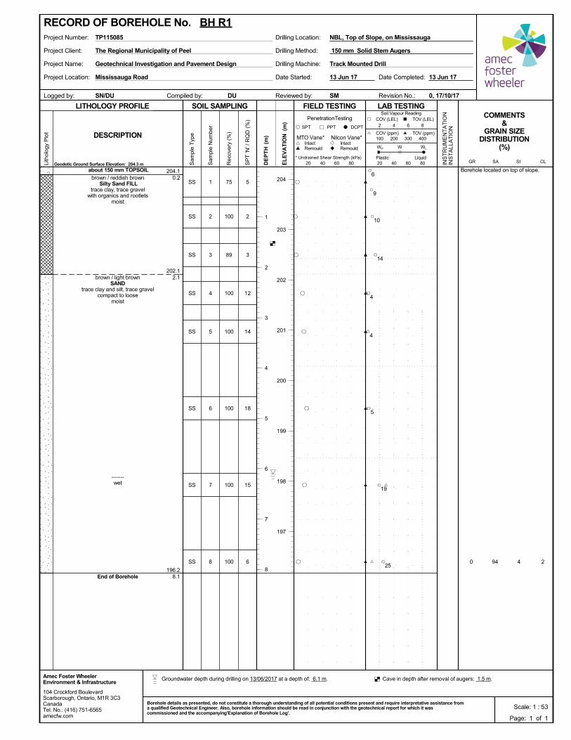
75
100
89
100
100
100
100
100 94 4 2
204.1
202.1
196.2
0.2
2.1
8.1
0
5
2
3
12
14
18
15
6
Borehole located on top of slope.
1
2
3
4
5
6
7
8
SS
SS
SS
SS
SS
SS
SS
SS
about 150 mm TOPSOIL
brown / reddish brownSilty Sand FILL
trace clay, trace gravelwith organics and rootlets
moist
brown / light brownSAND
trace clay and silt, trace gravelcompact to loose
moist
-------wet
End of Borehole
Project Client:
Project Name:
Project Location:
Drilling Machine:
Drilling Method:
Drilling Location:Project Number: NBL, Top of Slope, on Mississauga
Reviewed by:Compiled by:Logged by:
TP115085
DU
Date Started:
Track Mounted DrillGeotechnical Investigation and Pavement Design
Revision No.:
13 Jun 17
The Regional Municipality of Peel
Mississauga Road
0, 17/10/17SMSN/DU
Date Completed: 13 Jun 17
150 mm Solid Stem Augers
SOIL SAMPLING
Sam
ple
Typ
e
Sam
ple
Num
ber
LITHOLOGY PROFILE FIELD TESTING
Rec
over
y (%
)
Lith
olog
y P
lot
LAB TESTINGCOMMENTS
&GRAIN SIZE
DISTRIBUTION(%)
SP
T 'N
' / R
QD
(%
)
Geodetic Ground Surface Elevation: 204.3 m
DCPT
* Undrained Shear Strength (kPa)
(m)
(m)
EL
EV
AT
IONDESCRIPTION
20 40 60 80
Intact
INS
TR
UM
EN
TA
TIO
NIN
ST
ALL
AT
ION
Remould
PenetrationTesting
SPT PPT
DE
PT
H RemouldIntact
Nilcon Vane*MTO Vane*
Liquid
WP
20 40 60 80
Soil Vapour Reading
W WL
TOV (ppm)100 200 300 400
2 4 6 8
COV (ppm)
COV (LEL) TOV (LEL)
PlasticCLSISAGR
104 Crockford BoulevardScarborough, Ontario, M1R 3C3CanadaTel. No.: (416) 751-6565amecfw.com
Amec Foster WheelerEnvironment & Infrastructure
Scale: 1 : 53Borehole details as presented, do not constitute a thorough understanding of all potential conditions present and require interpretative assistance froma qualified Geotechnical Engineer. Also, borehole information should be read in conjunction with the geotechnical report for which it wascommissioned and the accompanying'Explanation of Borehole Log'.
204
203
202
201
200
199
198
197
RECORD OF BOREHOLE No. BH R1
Page: 1 of 1
1
2
3
4
5
6
7
8
6
9
10
14
4
4
5
19
25
Groundwater depth during drilling on 13/06/2017 at a depth of: 6.1 m. Cave in depth after removal of augers: 1.5 m.
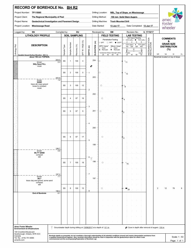
100
100
100
67
67
67
100
100 12 78 8
204.0
202.9
198.7
197.2
196.2
0.3
1.4
5.6
7.1
8.1
2
4
5
12
16
9
17
18
15
Borehole located on top of slope.
1
2
3
4
5
6
7
8
SS
SS
SS
SS
SS
SS
SS
SS
about 150 mm TOPSOIL
brownSilty Sand FILL
moist
brownSAND
trace silt, trace gravelloose to compact
moist
brownSILTY SAND
compactwet
brownSILT
trace clay and gravel, some sandcompact
wet
End of Borehole
Project Client:
Project Name:
Project Location:
Drilling Machine:
Drilling Method:
Drilling Location:Project Number: NBL, Top of Slope, on Mississauga
Reviewed by:Compiled by:Logged by:
TP115085
DU
Date Started:
Track Mounted DrillGeotechnical Investigation and Pavement Design
Revision No.:
13 Jun 17
The Regional Municipality of Peel
Mississauga Road
0, 17/10/17SMSN
Date Completed: 13 Jun 17
150 mm Solid Stem Augers
SOIL SAMPLING
Sam
ple
Typ
e
Sam
ple
Num
ber
LITHOLOGY PROFILE FIELD TESTING
Rec
over
y (%
)
Lith
olog
y P
lot
LAB TESTINGCOMMENTS
&GRAIN SIZE
DISTRIBUTION(%)
SP
T 'N
' / R
QD
(%
)
Geodetic Ground Surface Elevation: 204.3 m
DCPT
* Undrained Shear Strength (kPa)
(m)
(m)
EL
EV
AT
IONDESCRIPTION
20 40 60 80
Intact
INS
TR
UM
EN
TA
TIO
NIN
ST
ALL
AT
ION
Remould
PenetrationTesting
SPT PPT
DE
PT
H RemouldIntact
Nilcon Vane*MTO Vane*
Liquid
WP
20 40 60 80
Soil Vapour Reading
W WL
TOV (ppm)100 200 300 400
2 4 6 8
COV (ppm)
COV (LEL) TOV (LEL)
PlasticCLSISAGR
104 Crockford BoulevardScarborough, Ontario, M1R 3C3CanadaTel. No.: (416) 751-6565amecfw.com
Amec Foster WheelerEnvironment & Infrastructure
Scale: 1 : 53Borehole details as presented, do not constitute a thorough understanding of all potential conditions present and require interpretative assistance froma qualified Geotechnical Engineer. Also, borehole information should be read in conjunction with the geotechnical report for which it wascommissioned and the accompanying'Explanation of Borehole Log'.
204
203
202
201
200
199
198
197
RECORD OF BOREHOLE No. BH R2
Page: 1 of 1
1
2
3
4
5
6
7
8
11
13
8
4
2
2
15
20
Groundwater depth during drilling on 13/06/2017 at a depth of: 6.1 m. Cave in depth after removal of augers: 0.6 m.
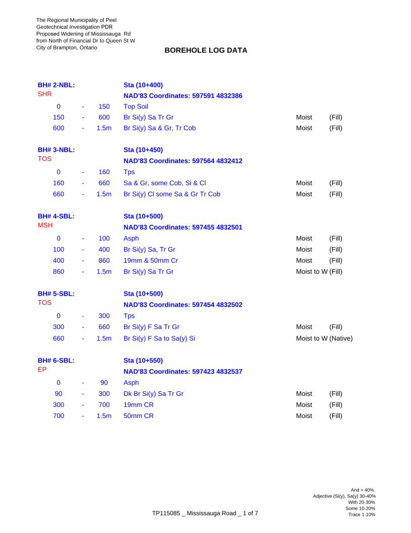
BOREHOLE LOG DATA
BH# 2-NBL: Sta (10+400)SHR
0 - 150 Top Soil
150 - 600 Br Si(y) Sa Tr Gr Moist (Fill)
600 - 1.5m Br Si(y) Sa & Gr, Tr Cob Moist (Fill)
BH# 3-NBL: Sta (10+450)TOS
0 - 160 Tps
160 - 660 Sa & Gr, some Cob, Si & Cl Moist (Fill)
660 - 1.5m Br Si(y) Cl some Sa & Gr Tr Cob Moist (Fill)
BH# 4-SBL: Sta (10+500)MSH
0 - 100 Asph Moist (Fill)
100 - 400 Br Si(y) Sa, Tr Gr Moist (Fill)
400 - 860 19mm & 50mm Cr Moist (Fill)
860 - 1.5m Br Si(y) Sa Tr Gr Moist to W (Fill)
BH# 5-SBL: Sta (10+500)TOS
0 - 300 Tps
300 - 660 Br Si(y) F Sa Tr Gr Moist (Fill)
660 - 1.5m Br Si(y) F Sa to Sa(y) Si Moist to W (Native)
BH# 6-SBL: Sta (10+550)EP
0 - 90 Asph
90 - 300 Dk Br Si(y) Sa Tr Gr Moist (Fill)
300 - 700 19mm CR Moist (Fill)
700 - 1.5m 50mm CR Moist (Fill)
NAD'83 Coordinates: 597591 4832386
NAD'83 Coordinates: 597564 4832412
NAD'83 Coordinates: 597455 4832501
NAD'83 Coordinates: 597454 4832502
NAD'83 Coordinates: 597423 4832537
TP115085 _ Mississauga Road _ 1 of 7
And > 40%.Adjective (Si(y), Sa(y) 30-40%
With 20-30%Some 10-20%
Trace 1-10%
The Regional Municipality of PeelGeotechnical Investigation PDR Proposed Widening of Mississauga Rdfrom North of Financial Dr to Queen St WCity of Brampton, Ontario
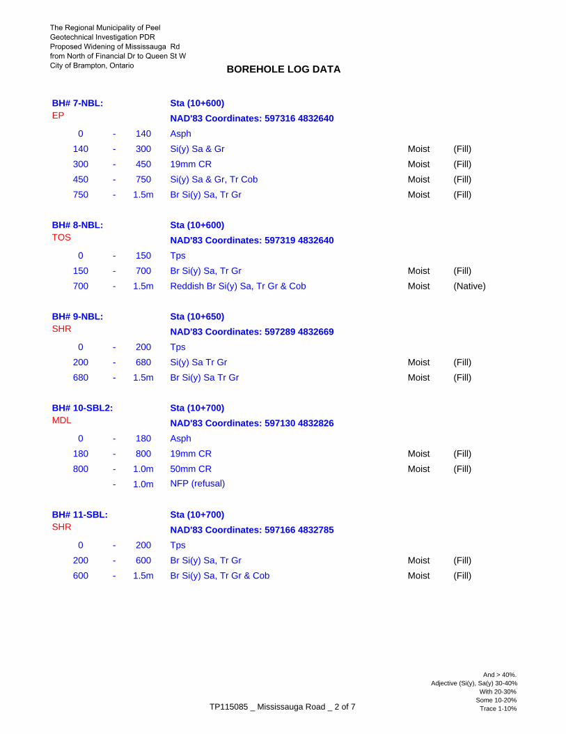
BOREHOLE LOG DATA
BH# 7-NBL: Sta (10+600)EP
0 - 140 Asph
140 - 300 Si(y) Sa & Gr Moist (Fill)
300 - 450 19mm CR Moist (Fill)
450 - 750 Si(y) Sa & Gr, Tr Cob Moist (Fill)
750 - 1.5m Br Si(y) Sa, Tr Gr Moist (Fill)
BH# 8-NBL: Sta (10+600)TOS
0 - 150 Tps
150 - 700 Br Si(y) Sa, Tr Gr Moist (Fill)
700 - 1.5m Reddish Br Si(y) Sa, Tr Gr & Cob Moist (Native)
BH# 9-NBL: Sta (10+650)SHR
0 - 200 Tps
200 - 680 Si(y) Sa Tr Gr Moist (Fill)
680 - 1.5m Br Si(y) Sa Tr Gr Moist (Fill)
BH# 10-SBL2: Sta (10+700)MDL
0 - 180 Asph
180 - 800 19mm CR Moist (Fill)
800 - 1.0m 50mm CR Moist (Fill)
- 1.0m NFP (refusal)
BH# 11-SBL: Sta (10+700)SHR
0 - 200 Tps
200 - 600 Br Si(y) Sa, Tr Gr Moist (Fill)
600 - 1.5m Br Si(y) Sa, Tr Gr & Cob Moist (Fill)
NAD'83 Coordinates: 597316 4832640
NAD'83 Coordinates: 597319 4832640
NAD'83 Coordinates: 597289 4832669
NAD'83 Coordinates: 597130 4832826
NAD'83 Coordinates: 597166 4832785
TP115085 _ Mississauga Road _ 2 of 7
And > 40%.Adjective (Si(y), Sa(y) 30-40%
With 20-30%Some 10-20%
Trace 1-10%
The Regional Municipality of PeelGeotechnical Investigation PDR Proposed Widening of Mississauga Rdfrom North of Financial Dr to Queen St WCity of Brampton, Ontario
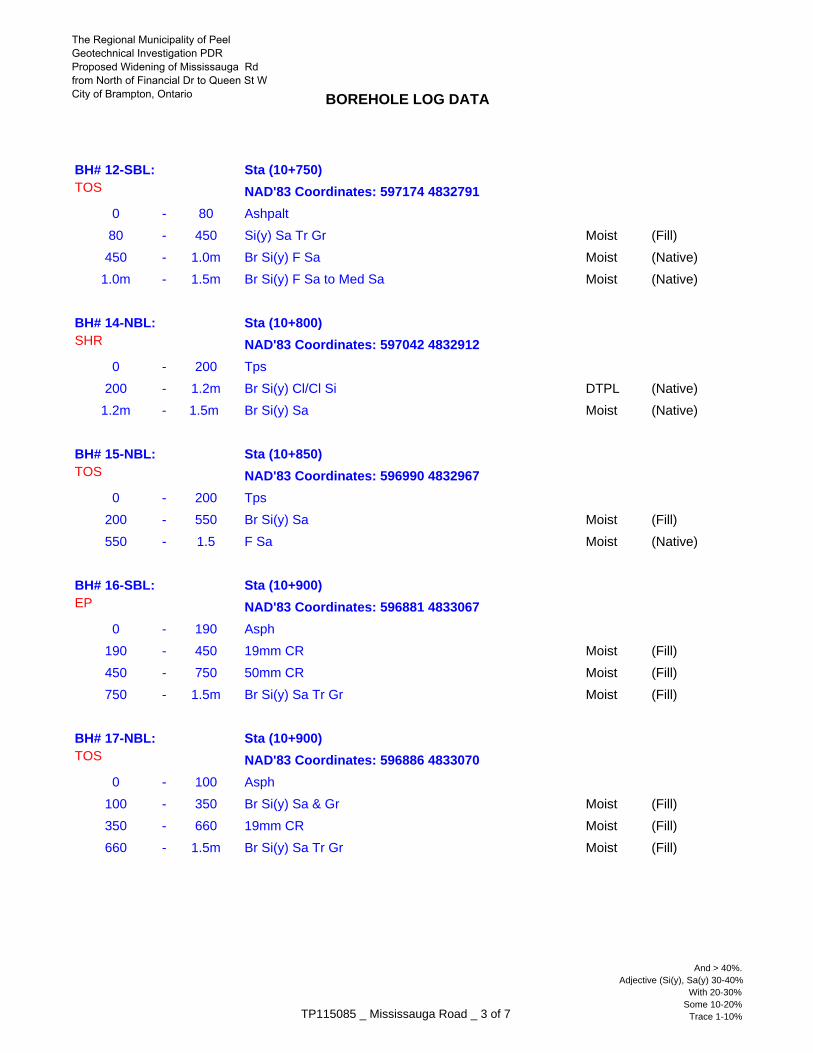
BOREHOLE LOG DATA
BH# 12-SBL: Sta (10+750)TOS
0 - 80 Ashpalt
80 - 450 Si(y) Sa Tr Gr Moist (Fill)
450 - 1.0m Br Si(y) F Sa Moist (Native)
1.0m - 1.5m Br Si(y) F Sa to Med Sa Moist (Native)
BH# 14-NBL: Sta (10+800) SHR
0 - 200 Tps
200 - 1.2m Br Si(y) Cl/Cl Si DTPL (Native)
1.2m - 1.5m Br Si(y) Sa Moist (Native)
BH# 15-NBL: Sta (10+850) TOS
0 - 200 Tps
200 - 550 Br Si(y) Sa Moist (Fill)
550 - 1.5 F Sa Moist (Native)
BH# 16-SBL: Sta (10+900)EP
0 - 190 Asph
190 - 450 19mm CR Moist (Fill)
450 - 750 50mm CR Moist (Fill)
750 - 1.5m Br Si(y) Sa Tr Gr Moist (Fill)
BH# 17-NBL: Sta (10+900) TOS
0 - 100 Asph
100 - 350 Br Si(y) Sa & Gr Moist (Fill)
350 - 660 19mm CR Moist (Fill)
660 - 1.5m Br Si(y) Sa Tr Gr Moist (Fill)
NAD'83 Coordinates: 597174 4832791
NAD'83 Coordinates: 597042 4832912
NAD'83 Coordinates: 596990 4832967
NAD'83 Coordinates: 596881 4833067
NAD'83 Coordinates: 596886 4833070
TP115085 _ Mississauga Road _ 3 of 7
And > 40%.Adjective (Si(y), Sa(y) 30-40%
With 20-30%Some 10-20%
Trace 1-10%
The Regional Municipality of PeelGeotechnical Investigation PDR Proposed Widening of Mississauga Rdfrom North of Financial Dr to Queen St WCity of Brampton, Ontario
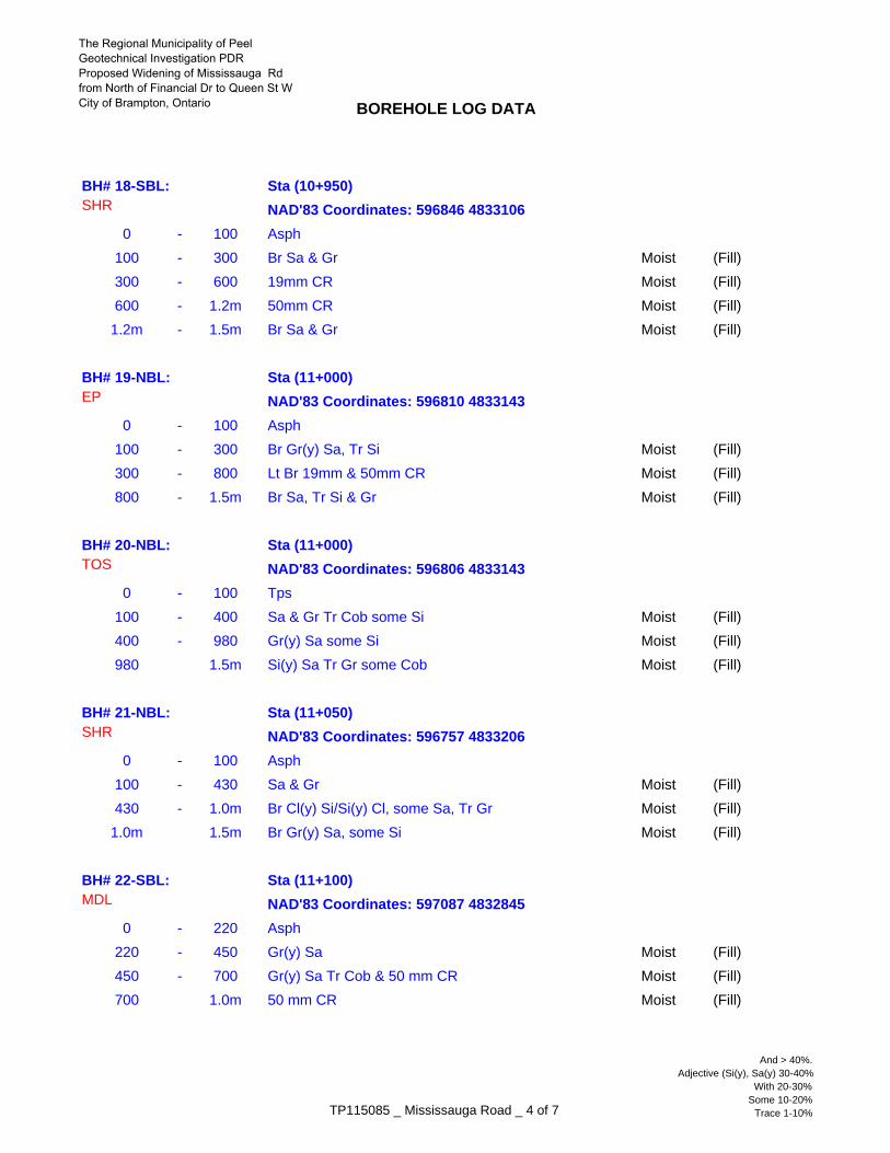
BOREHOLE LOG DATA
BH# 18-SBL: Sta (10+950) SHR
0 - 100 Asph
100 - 300 Br Sa & Gr Moist (Fill)
300 - 600 19mm CR Moist (Fill)
600 - 1.2m 50mm CR Moist (Fill)
1.2m - 1.5m Br Sa & Gr Moist (Fill)
BH# 19-NBL: Sta (11+000)EP
0 - 100 Asph
100 - 300 Br Gr(y) Sa, Tr Si Moist (Fill)
300 - 800 Lt Br 19mm & 50mm CR Moist (Fill)
800 - 1.5m Br Sa, Tr Si & Gr Moist (Fill)
BH# 20-NBL: Sta (11+000) TOS
0 - 100 Tps
100 - 400 Sa & Gr Tr Cob some Si Moist (Fill)
400 - 980 Gr(y) Sa some Si Moist (Fill)
980 1.5m Si(y) Sa Tr Gr some Cob Moist (Fill)
BH# 21-NBL: Sta (11+050) SHR
0 - 100 Asph
100 - 430 Sa & Gr Moist (Fill)
430 - 1.0m Br Cl(y) Si/Si(y) Cl, some Sa, Tr Gr Moist (Fill)
1.0m 1.5m Br Gr(y) Sa, some Si Moist (Fill)
BH# 22-SBL: Sta (11+100)MDL
0 - 220 Asph
220 - 450 Gr(y) Sa Moist (Fill)
450 - 700 Gr(y) Sa Tr Cob & 50 mm CR Moist (Fill)
700 1.0m 50 mm CR Moist (Fill)
NAD'83 Coordinates: 596846 4833106
NAD'83 Coordinates: 596810 4833143
NAD'83 Coordinates: 596806 4833143
NAD'83 Coordinates: 596757 4833206
NAD'83 Coordinates: 597087 4832845
TP115085 _ Mississauga Road _ 4 of 7
And > 40%.Adjective (Si(y), Sa(y) 30-40%
With 20-30%Some 10-20%
Trace 1-10%
The Regional Municipality of PeelGeotechnical Investigation PDR Proposed Widening of Mississauga Rdfrom North of Financial Dr to Queen St WCity of Brampton, Ontario
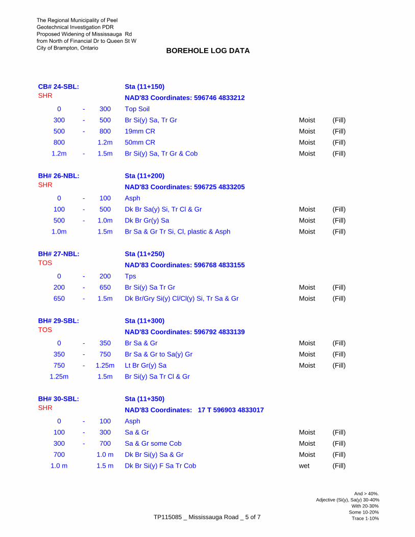
BOREHOLE LOG DATA
CB# 24-SBL: Sta (11+150) SHR
0 - 300 Top Soil
300 - 500 Br Si(y) Sa, Tr Gr Moist (Fill)
500 - 800 19mm CR Moist (Fill)
800 1.2m 50mm CR Moist (Fill)
1.2m - 1.5m Br Si(y) Sa, Tr Gr & Cob Moist (Fill)
BH# 26-NBL: Sta (11+200) SHR
0 - 100 Asph
100 - 500 Dk Br Sa(y) Si, Tr Cl & Gr Moist (Fill)
500 - 1.0m Dk Br Gr(y) Sa Moist (Fill)
1.0m 1.5m Br Sa & Gr Tr Si, Cl, plastic & Asph Moist (Fill)
BH# 27-NBL: Sta (11+250) TOS
0 - 200 Tps
200 - 650 Br Si(y) Sa Tr Gr Moist (Fill)
650 - 1.5m Dk Br/Gry Si(y) Cl/Cl(y) Si, Tr Sa & Gr Moist (Fill)
BH# 29-SBL: Sta (11+300) TOS
0 - 350 Br Sa & Gr Moist (Fill)
350 - 750 Br Sa & Gr to Sa(y) Gr Moist (Fill)
750 - 1.25m Lt Br Gr(y) Sa Moist (Fill)
1.25m 1.5m Br Si(y) Sa Tr Cl & Gr
BH# 30-SBL: Sta (11+350) SHR
0 - 100 Asph
100 - 300 Sa & Gr Moist (Fill)
300 - 700 Sa & Gr some Cob Moist (Fill)
700 1.0 m Dk Br Si(y) Sa & Gr Moist (Fill)
1.0 m 1.5 m Dk Br Si(y) F Sa Tr Cob wet (Fill)
NAD'83 Coordinates: 596746 4833212
NAD'83 Coordinates: 596725 4833205
NAD'83 Coordinates: 596768 4833155
NAD'83 Coordinates: 596792 4833139
NAD'83 Coordinates: 17 T 596903 4833017
TP115085 _ Mississauga Road _ 5 of 7
And > 40%.Adjective (Si(y), Sa(y) 30-40%
With 20-30%Some 10-20%
Trace 1-10%
The Regional Municipality of PeelGeotechnical Investigation PDR Proposed Widening of Mississauga Rdfrom North of Financial Dr to Queen St WCity of Brampton, Ontario
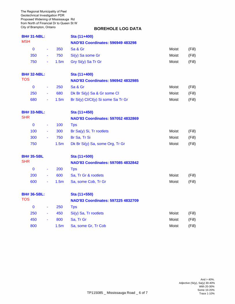
BOREHOLE LOG DATA
BH# 31-NBL: Sta (11+400) MSH
0 - 350 Sa & Gr Moist (Fill)
350 - 750 Si(y) Sa some Gr Moist (Fill)
750 - 1.5m Gry Si(y) Sa Tr Gr Moist (Fill)
BH# 32-NBL: Sta (11+400) TOS
0 - 250 Sa & Gr Moist (Fill)
250 - 680 Dk Br Si(y) Sa & Gr some Cl Moist (Fill)
680 - 1.5m Br Si(y) Cl/Cl(y) Si some Sa Tr Gr Moist (Fill)
BH# 33-NBL: Sta (11+450) SHR
0 - 100 Tps
100 - 300 Br Sa(y) Si, Tr rootlets Moist (Fill)
300 - 750 Br Sa, Tr Si Moist (Fill)
750 1.5m Dk Br Si(y) Sa, some Org, Tr Gr Moist (Fill)
BH# 35-SBL Sta (11+500) SHR
0 - 200 Tps
200 - 600 Sa, Tr Gr & rootlets Moist (Fill)
600 - 1.5m Sa, some Cob, Tr Gr Moist (Fill)
BH# 36-SBL: Sta (11+550) TOS
0 - 250 Tps
250 - 450 Si(y) Sa, Tr rootlets Moist (Fill)
450 - 800 Sa, Tr Gr Moist (Fill)
800 1.5m Sa, some Gr, Tr Cob Moist (Fill)
NAD'83 Coordinates: 596949 483298
NAD'83 Coordinates: 596942 4832985
NAD'83 Coordinates: 597052 4832869
NAD'83 Coordinates: 597085 4832842
NAD'83 Coordinates: 597225 4832709
TP115085 _ Mississauga Road _ 6 of 7
And > 40%.Adjective (Si(y), Sa(y) 30-40%
With 20-30%Some 10-20%
Trace 1-10%
The Regional Municipality of PeelGeotechnical Investigation PDR Proposed Widening of Mississauga Rdfrom North of Financial Dr to Queen St WCity of Brampton, Ontario
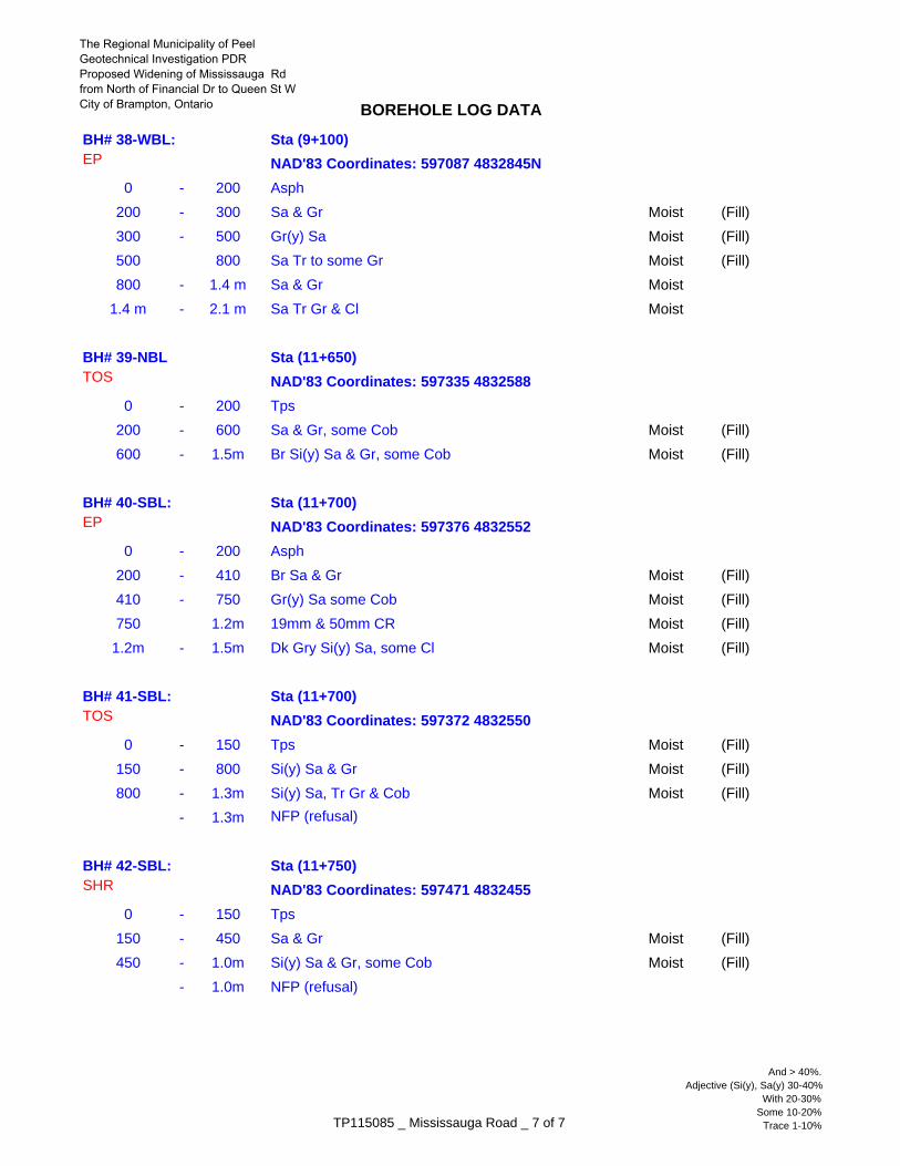
BOREHOLE LOG DATA
BH# 38-WBL: Sta (9+100) EP
0 - 200 Asph
200 - 300 Sa & Gr Moist (Fill)
300 - 500 Gr(y) Sa Moist (Fill)
500 800 Sa Tr to some Gr Moist (Fill)
800 - 1.4 m Sa & Gr Moist
1.4 m - 2.1 m Sa Tr Gr & Cl Moist
BH# 39-NBL Sta (11+650) TOS
0 - 200 Tps
200 - 600 Sa & Gr, some Cob Moist (Fill)
600 - 1.5m Br Si(y) Sa & Gr, some Cob Moist (Fill)
BH# 40-SBL: Sta (11+700) EP
0 - 200 Asph
200 - 410 Br Sa & Gr Moist (Fill)
410 - 750 Gr(y) Sa some Cob Moist (Fill)
750 1.2m 19mm & 50mm CR Moist (Fill)
1.2m - 1.5m Dk Gry Si(y) Sa, some Cl Moist (Fill)
BH# 41-SBL: Sta (11+700) TOS
0 - 150 Tps Moist (Fill)
150 - 800 Si(y) Sa & Gr Moist (Fill)
800 - 1.3m Si(y) Sa, Tr Gr & Cob Moist (Fill)
- 1.3m NFP (refusal)
BH# 42-SBL: Sta (11+750) SHR
0 - 150 Tps
150 - 450 Sa & Gr Moist (Fill)
450 - 1.0m Si(y) Sa & Gr, some Cob Moist (Fill)
- 1.0m NFP (refusal)
NAD'83 Coordinates: 597335 4832588
NAD'83 Coordinates: 597376 4832552
NAD'83 Coordinates: 597087 4832845N
NAD'83 Coordinates: 597372 4832550
NAD'83 Coordinates: 597471 4832455
TP115085 _ Mississauga Road _ 7 of 7
And > 40%.Adjective (Si(y), Sa(y) 30-40%
With 20-30%Some 10-20%
Trace 1-10%
The Regional Municipality of PeelGeotechnical Investigation PDR Proposed Widening of Mississauga Rdfrom North of Financial Dr to Queen St WCity of Brampton, Ontario
APPENDIX A SITE PHOTOGRAPHS
FALLING WEIGHT DEFLECTOMETER ANALYSIS
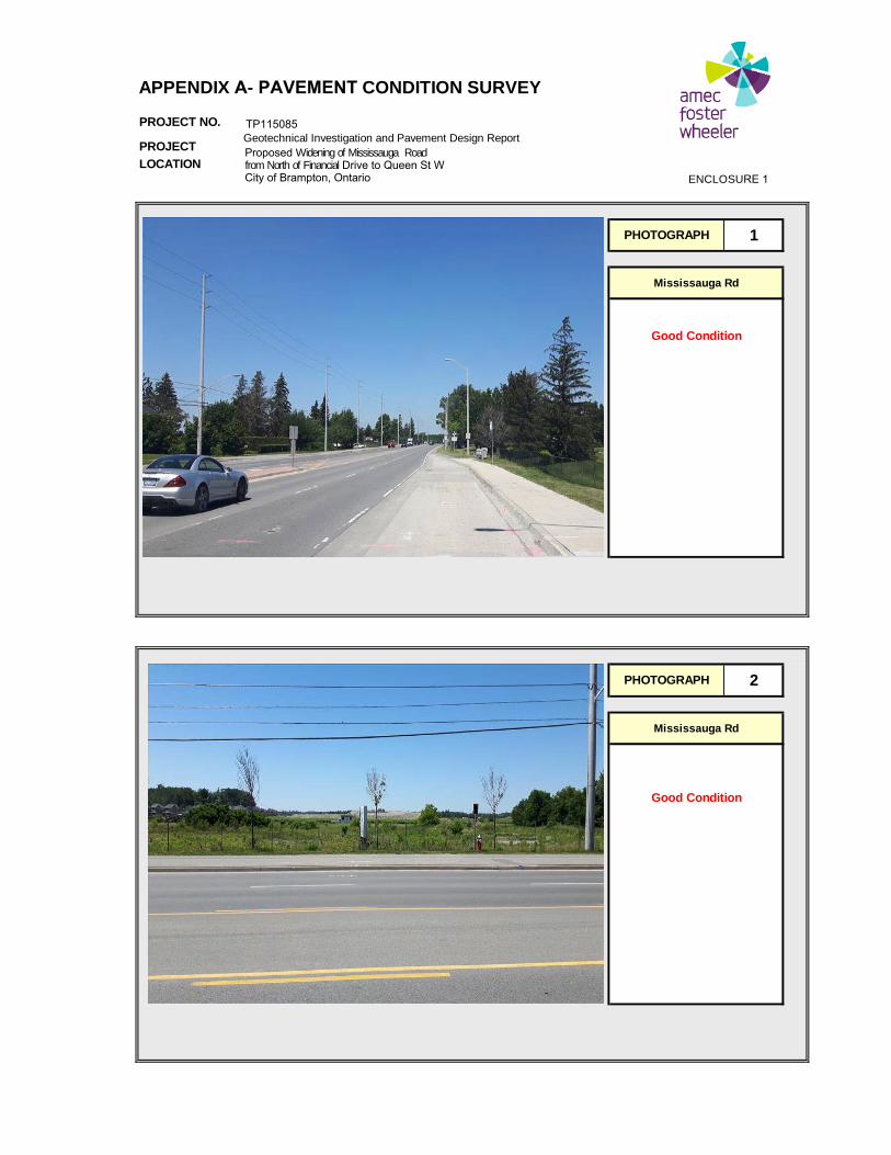
PROJECT NO.
PROJECT
LOCATION
Geotechnical Investigation and Pavement Design Report
Mississauga Rd
Good Condition
Good Condition
PHOTOGRAPH 1
Mississauga Rd
PHOTOGRAPH 2
Proposed Widening of Mississauga Road from North of Financial Drive to Queen St W City of Brampton, Ontario
ENCLOSURE 1
APPENDIX A- PAVEMENT CONDITION SURVEY
TP115085
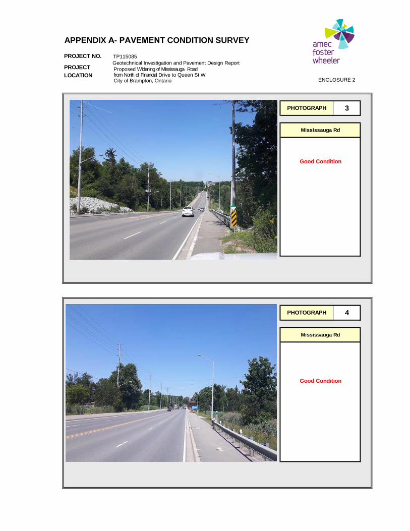
PROJECT NO.
PROJECT
LOCATION
Geotechnical Investigation and Pavement Design Report
Mississauga Rd
Good Condition
Good Condition
PHOTOGRAPH 3
Mississauga Rd
PHOTOGRAPH 4
Proposed Widening of Mississauga Road from North of Financial Drive to Queen St W City of Brampton, Ontario
ENCLOSURE 2
APPENDIX A- PAVEMENT CONDITION SURVEY
TP115085
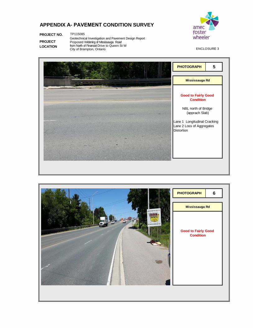
PROJECT NO.
PROJECT
LOCATION
Lane 1 Longitudinal CrackingLane 2 Loss of AggregatesDistortion
Good to Fairly Good
PHOTOGRAPH 5
Mississauga Rd
PHOTOGRAPH
Condition
Mississauga Rd
Good to Fairly Good Condition
NBL north of Bridge (apprach Slab)
6
Geotechnical Investigation and Pavement Design Report Proposed Widening of Mississauga Road from North of Financial Drive to Queen St W City of Brampton, Ontario
ENCLOSURE 3
APPENDIX A- PAVEMENT CONDITION SURVEY
TP115085
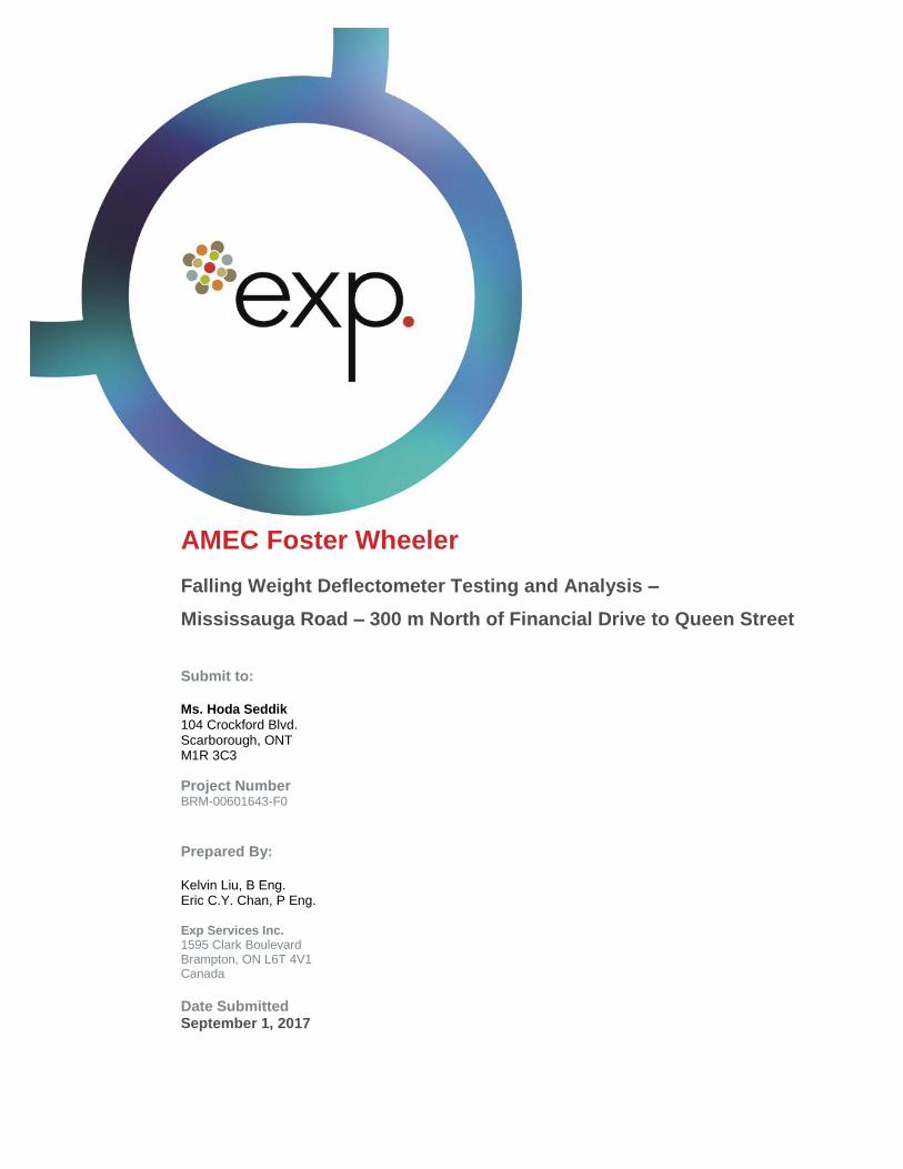
AMEC Foster Wheeler
Falling Weight Deflectometer Testing and Analysis –
Mississauga Road – 300 m North of Financial Drive to Queen Street
Submit to:
Ms. Hoda Seddik
104 Crockford Blvd. Scarborough, ONT M1R 3C3
Project Number BRM-00601643-F0
Prepared By:
Kelvin Liu, B Eng. Eric C.Y. Chan, P Eng. Exp Services Inc. 1595 Clark Boulevard Brampton, ON L6T 4V1 Canada
Date Submitted September 1, 2017
Client: AMEC Foster Wheeler Project Name: FWD Testing for AMEC Foster Wheeler, Mississauga Road – Financial Drive to Queen Street
Project Number: BRM-00601643-F0 Date: September 1, 2017
2
1. Introduction
AMEC Foster Wheeler (AMECFW) retained Exp Services Inc. (exp) to undertake Falling Weight
Deflectometer (FWD) testing for Mississauga Road from 300 m North of Financial Drive to
approximately 300 m North of Queen Street West, Brampton, Ontario.
The project employed the use of Exp’s Heavy Weight Deflectometer (HWD) to perform field testing at
approximately 50 meters intervals in each travelled lanes and directions. The HWD testing machine is
fully adaptable to the conventional FWD machine, which the HWD is capable of generating greater
dynamic loads up to 210 kN when necessary (i.e. to simulate heavy aircraft such as Boeing 747). In
this project, part of the weight was removed such that the dynamic load is applied in the range of
30kN~75kN, and normalized to 40kN for conventional asphalt pavement testing.
The pavement structure of various sections were provided by AMECFW and used for data analysis
purposes. The data analysis protocol adopted for this project included the backcalculation of the in-
situ subgrade resilient modules, pavement structure number and normalized deflection analysis that
can be used to estimate pavement structural adequacy.
2. Scope
On July 13, 2017, exp undertook FWD testing on the subject pavement sections in order to estimate
the in-situ structural capacity of the pavements. The objective of this testing is to provide the
necessary information for AMECFW to ascertain the existing pavement structure adequacy.
Compilation of data collected from the field investigation and the backcalculation results are presented
in this report for information purposes.
To achieve this objective, exp has performed the following works:
1. In-Situ FWD testing with 50m interval staggered within each pavement sections in all lanes
and travelled directions;
2. Ambient and Asphalt Surface temperature measurements;
3. Deflection Normalization to 21oC and Deflection Area Basin analysis;
4. Subgrade Resilient Modules analysis; and,
5. Structural Number estimation conforms to 1993 ASSHTO Pavement Design Guide.
Client: AMEC Foster Wheeler Project Name: FWD Testing for AMEC Foster Wheeler, Mississauga Road – Financial Drive to Queen Street
Project Number: BRM-00601643-F0 Date: September 1, 2017
3
3. Test Section
The subject pavement sections are in the City of Brampton within the Regional Municipality of Peel.
All pavement sections are located on Mississauga Road from 300 m North of Financial Drive to
approximately 300 m North of Queen Street West. It should be noted that at the time of testing, there
were construction activities North of Queen Street. Therefore, testing was not conducted from Queen
Street West to the North limit. Testing sections are summarized below:
• Section 1: Mississauga Road Northbound Lane 1 (~300 m North of Financial Drive to Queen
Street).
• Section 2: Mississauga Road Northbound Lane 2 (~300 m North of Financial Drive to Queen
Street).
• Section 3: Mississauga Road Southbound Lane 1 (From Queen Street to ~300 m North of
Financial Drive).
• Section 4: Mississauga Road Southbound Lane 2 (From Queen Street to ~300 m North of
Financial Drive).
Based upon the pavement layer thicknesses provided by AMECFW, it was determined that the subject
pavement sections are composed of layers of hot mix asphalt layers, on top of granular layers (base
and subbase). This pavement structure information was used for estimating the structure number and
resilient modules of the subgrade layer.
4. Field Works
4.1 FWD Testing Protocol
The FWD machine operated by exp Services Inc. was used to apply a dynamic load on the pavement
varying from 30 kN to 75 kN (four (4) drops per location). The Strategic Highways Research Program
(SHRP) specifies the locations of the sensors, and the minimum number of loading drops that are to
be applied to a pavement section, so that the standard deviation and variance in the backcalculated
results can be ascertained. The sensor spacing was set as per standard protocols as 0 mm, 200 mm,
300 mm, 450 mm, 600 mm, 900 mm, 1200 mm, 1500 mm and 1800 mm (which are in accordance
with the SHRP specifications).
The FWD applies an impact load to the pavement surface, and measures the surface deformation
(called deflection basin), using nine geophones. This data is recorded by the data acquisition system,
and then used to backcalculate the material properties of individual layers, if the thicknesses are
known. This process can also be performed vice-versa in order to determine the layer thicknesses, if
the material properties are known (laboratory mechanical tests).
Client: AMEC Foster Wheeler Project Name: FWD Testing for AMEC Foster Wheeler, Mississauga Road – Financial Drive to Queen Street
Project Number: BRM-00601643-F0 Date: September 1, 2017
4
It is also important to determine the surface, sub-surface and ambient air temperatures at the time of
the testing, because it is critical for adjusting the backcalculated moduli of hot-mix asphalt (HMA),
which has high thermal susceptibility. For the project specified testing plan, the ambient air
temperatures and the pavement surface temperatures were detected on site using the thermal gun
attached to the data acquisition system. These temperatures were further used to calculate the
asphalt layer temperature with last 24 hours mean temperature by Bell equation.
Once the FWD data for various roads was obtained, a normalized deflection and deflection ratio
coupled with the area of deflection basin analysis. This phase of testing yielded thickness information
of various layers that were used to estimate the Structural number of the pavement structure.
4.2 Normalization of Deflection Data
The data collected from the pavement sections using the FWD is stored in ASCII file format.
Normalization of the FWD data to 40 kN applied load at 21 C temperature was performed to estimate
the structural capacity of the existing pavement. The deflection basin profile and individual
deflections approximate the existing condition of the pavement that is being tested using the FWD
machine. The criteria that are widely used in the industry and employed in this study are as follows:
1. do: Centre Plate Deflection (Primarily measures the subgrade strength and the pavement
stiffness) – Maximum 0.5 mm;
2. do/d200: Ratio of Centre Plate Deflection to Sensor Deflection at 200 mm from the Centre Plate
(subgrade strength verses other structural strengths) – Maximum 1.4 mm;
3. Normalized Area: Area of the Deflection Basin (overall ability of the pavement to effectively
distribute vehicular loading) – Minimum 600 mm.
4.3 Backcalculation of Composite Modules, Subgrade Resilient Modules and Effective Structural Number
Once the deflection profile was available for each drop, the backcalculated pavement composite
modules was estimated using the following equation as detailed by MTO and derived from the
National Cooperative Highway Research Program (NCHRP) Study was used for the calculation of
composite moduli of the tested pavement (1).
where:
Eo = Composite modulus of the entire pavement system beneath the load plate f = Factor for stress distribution (using 2) v = Poisson’s ratio
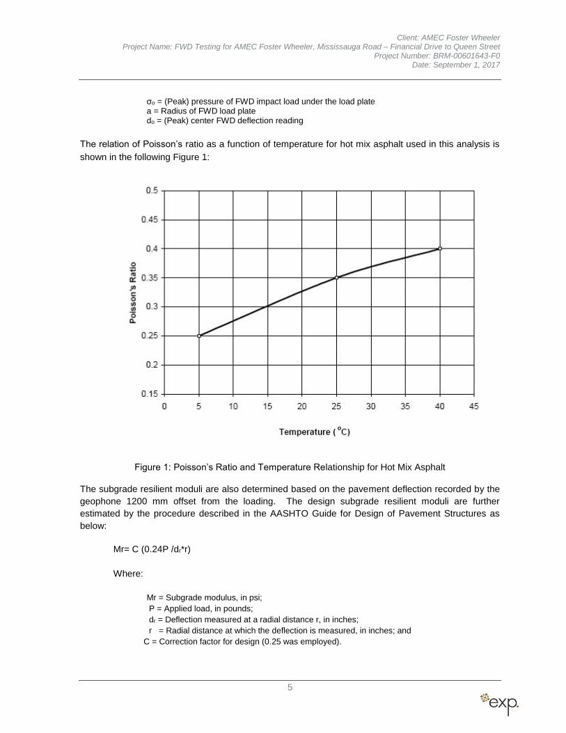
Client: AMEC Foster Wheeler Project Name: FWD Testing for AMEC Foster Wheeler, Mississauga Road – Financial Drive to Queen Street
Project Number: BRM-00601643-F0 Date: September 1, 2017
5
σo = (Peak) pressure of FWD impact load under the load plate a = Radius of FWD load plate do = (Peak) center FWD deflection reading
The relation of Poisson’s ratio as a function of temperature for hot mix asphalt used in this analysis is
shown in the following Figure 1:
Figure 1: Poisson’s Ratio and Temperature Relationship for Hot Mix Asphalt
The subgrade resilient moduli are also determined based on the pavement deflection recorded by the
geophone 1200 mm offset from the loading. The design subgrade resilient moduli are further
estimated by the procedure described in the AASHTO Guide for Design of Pavement Structures as
below:
Mr= C (0.24P /dr*r)
Where:
Mr = Subgrade modulus, in psi;
P = Applied load, in pounds;
dr = Deflection measured at a radial distance r, in inches;
r = Radial distance at which the deflection is measured, in inches; and
C = Correction factor for design (0.25 was employed).
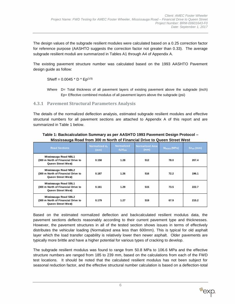
Client: AMEC Foster Wheeler Project Name: FWD Testing for AMEC Foster Wheeler, Mississauga Road – Financial Drive to Queen Street
Project Number: BRM-00601643-F0 Date: September 1, 2017
6
The design values of the subgrade resilient modules were calculated based on a 0.25 correction factor
for reference purpose (AASHTO suggests the correction factor not greater than 0.33). The average
subgrade resilient moduli are summarized in Tables A1 through A4 of Appendix A.
The existing pavement structure number was calculated based on the 1993 AASHTO Pavement
design guide as follow:
SNeff = 0.0045 * D * Ep(1/3)
Where D= Total thickness of all pavement layers of existing pavement above the subgrade (inch)
Ep= Effective combined modulus of all pavement layers above the subgrade (psi)
4.3.1 Pavement Structural Parameters Analysis
The details of the normalized deflection analysis, estimated subgrade resilient modules and effective
structural numbers for all pavement sections are attached to Appendix A of this report and are
summarized in Table 1 below.
Table 1: Backcalculation Summary as per AASHTO 1993 Pavement Design Protocol –
Mississauga Road from 300 m North of Financial Drive to Queen Street West
Road SectionsNormalized d0
(mm)
Normalized
d0/d200
Normalized Area
(mm)MRDES (MPa) Sneff (mm)
Mississauga Road NBL1
(300 m North of Financial Drive to
Queen Street West)
0.158 1.28 512 78.0 207.4
Mississauga Road NBL2
(300 m North of Financial Drive to
Queen Street West)
0.187 1.26 516 72.2 196.1
Mississauga Road SBL1
(300 m North of Financial Drive to
Queen Street West)
0.161 1.29 515 73.5 222.7
Mississauga Road SBL2
(300 m North of Financial Drive to
Queen Street West)
0.179 1.27 519 67.9 215.2
Based on the estimated normalized deflection and backcalculated resilient modulus data, the
pavement sections deflects reasonably according to their current pavement type and thicknesses.
However, the pavement structures in all of the tested section shows issues in terms of effectively
distributes the vehicular loading (Normalized area less than 600mm). This is typical for old asphalt
layer which the load transfer capability is relatively lower then newer asphalt. Older pavements are
typically more brittle and have a higher potential for various types of cracking to develop.
The subgrade resilient modulus was found to range from 50.8 MPa to 106.6 MPa and the effective
structure numbers are ranged from 185 to 239 mm, based on the calculations from each of the FWD
test locations. It should be noted that the calculated resilient modulus has not been subject for
seasonal reduction factor, and the effective structural number calculation is based on a deflection-total
Client: AMEC Foster Wheeler Project Name: FWD Testing for AMEC Foster Wheeler, Mississauga Road – Financial Drive to Queen Street
Project Number: BRM-00601643-F0 Date: September 1, 2017
8
6. References 1. “Manual for FWD Testing in the Long-Term Pavement Performance Program,” SHRP-P-661, PCS
Law Engineering and Braun Intertec Pavement, Inc. National Research Council, Washington, DC, 1993.
2. Pierce, L. M., “Development of a Computer Program for the Determination of the Area Value and Subgrade Resilient Modulus Using Dynatest FWD,” Report/Software by Washington State Department of Transportation, May 1999.
3. Anderson, P. D., “Cost-Effective Structural Rehabilitation of Pavements Using NDT Deflection Methods,” 1989.
4. Zhang, Z., Claros, G., Manuel, L., and Damnjanovic, I.,” Development of Structural Condition Index to Support Pavement Maintenance and Rehabilitation Decisions at Network Level,” Transportation Research Record No. 1827, pp. 10 – 17, 200
Client: AMEC Foster Wheeler Project Name: FWD Testing for AMEC Foster Wheeler, Mississauga Road – Financial Drive to Queen Street
Project Number: BRM-00601643-F0 Date: September 1, 2017
9
Appendix A – Deflection Normalization Data Subgrade Resilient Modules &
Existing Structural Numbers
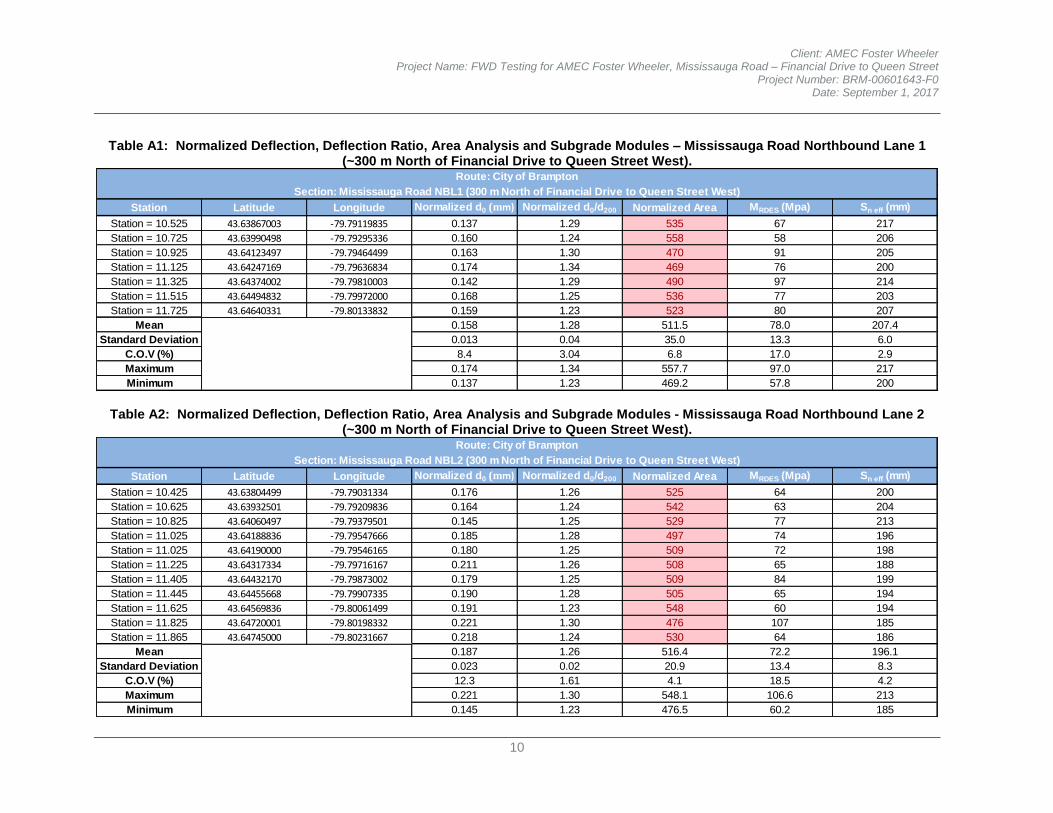
Client: AMEC Foster Wheeler Project Name: FWD Testing for AMEC Foster Wheeler, Mississauga Road – Financial Drive to Queen Street
Project Number: BRM-00601643-F0 Date: September 1, 2017
10
Table A1: Normalized Deflection, Deflection Ratio, Area Analysis and Subgrade Modules – Mississauga Road Northbound Lane 1 (~300 m North of Financial Drive to Queen Street West).
Station Latitude Longitude Normalized d0 (mm) Normalized d0/d200 Normalized Area MRDES (Mpa) Sn eff (mm)
Station = 10.525 43.63867003 -79.79119835 0.137 1.29 535 67 217
Station = 10.725 43.63990498 -79.79295336 0.160 1.24 558 58 206
Station = 10.925 43.64123497 -79.79464499 0.163 1.30 470 91 205
Station = 11.125 43.64247169 -79.79636834 0.174 1.34 469 76 200
Station = 11.325 43.64374002 -79.79810003 0.142 1.29 490 97 214
Station = 11.515 43.64494832 -79.79972000 0.168 1.25 536 77 203
Station = 11.725 43.64640331 -79.80133832 0.159 1.23 523 80 207
Mean 0.158 1.28 511.5 78.0 207.4
Standard Deviation 0.013 0.04 35.0 13.3 6.0
C.O.V (%) 8.4 3.04 6.8 17.0 2.9
Maximum 0.174 1.34 557.7 97.0 217
Minimum 0.137 1.23 469.2 57.8 200
Route: City of Brampton
Section: Mississauga Road NBL1 (300 m North of Financial Drive to Queen Street West)
Table A2: Normalized Deflection, Deflection Ratio, Area Analysis and Subgrade Modules - Mississauga Road Northbound Lane 2 (~300 m North of Financial Drive to Queen Street West).
Station Latitude Longitude Normalized d0 (mm) Normalized d0/d200 Normalized Area MRDES (Mpa) Sn eff (mm)
Station = 10.425 43.63804499 -79.79031334 0.176 1.26 525 64 200
Station = 10.625 43.63932501 -79.79209836 0.164 1.24 542 63 204
Station = 10.825 43.64060497 -79.79379501 0.145 1.25 529 77 213
Station = 11.025 43.64188836 -79.79547666 0.185 1.28 497 74 196
Station = 11.025 43.64190000 -79.79546165 0.180 1.25 509 72 198
Station = 11.225 43.64317334 -79.79716167 0.211 1.26 508 65 188
Station = 11.405 43.64432170 -79.79873002 0.179 1.25 509 84 199
Station = 11.445 43.64455668 -79.79907335 0.190 1.28 505 65 194
Station = 11.625 43.64569836 -79.80061499 0.191 1.23 548 60 194
Station = 11.825 43.64720001 -79.80198332 0.221 1.30 476 107 185
Station = 11.865 43.64745000 -79.80231667 0.218 1.24 530 64 186
Mean 0.187 1.26 516.4 72.2 196.1
Standard Deviation 0.023 0.02 20.9 13.4 8.3
C.O.V (%) 12.3 1.61 4.1 18.5 4.2
Maximum 0.221 1.30 548.1 106.6 213
Minimum 0.145 1.23 476.5 60.2 185
Route: City of Brampton
Section: Mississauga Road NBL2 (300 m North of Financial Drive to Queen Street West)
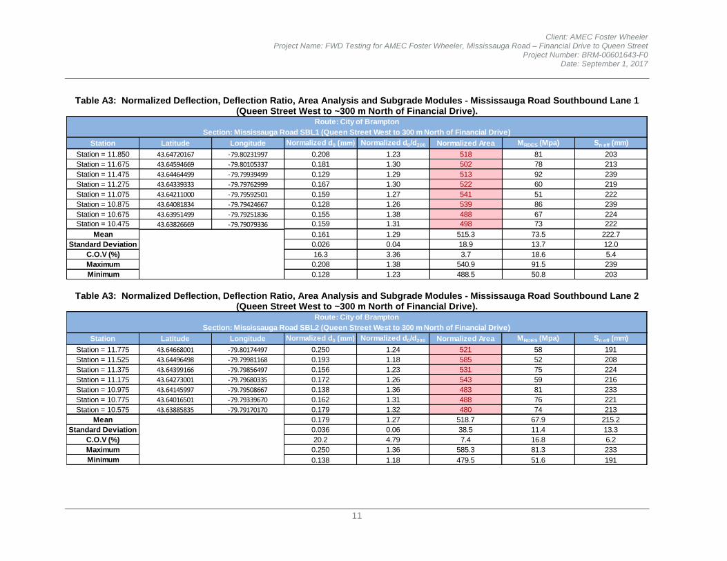
Client: AMEC Foster Wheeler Project Name: FWD Testing for AMEC Foster Wheeler, Mississauga Road – Financial Drive to Queen Street
Project Number: BRM-00601643-F0 Date: September 1, 2017
11
Table A3: Normalized Deflection, Deflection Ratio, Area Analysis and Subgrade Modules - Mississauga Road Southbound Lane 1 (Queen Street West to ~300 m North of Financial Drive).
Station Latitude Longitude Normalized d0 (mm) Normalized d0/d200 Normalized Area MRDES (Mpa) Sn eff (mm)
Station = 11.850 43.64720167 -79.80231997 0.208 1.23 518 81 203
Station = 11.675 43.64594669 -79.80105337 0.181 1.30 502 78 213
Station = 11.475 43.64464499 -79.79939499 0.129 1.29 513 92 239
Station = 11.275 43.64339333 -79.79762999 0.167 1.30 522 60 219
Station = 11.075 43.64211000 -79.79592501 0.159 1.27 541 51 222
Station = 10.875 43.64081834 -79.79424667 0.128 1.26 539 86 239
Station = 10.675 43.63951499 -79.79251836 0.155 1.38 488 67 224
Station = 10.475 43.63826669 -79.79079336 0.159 1.31 498 73 222
Mean 0.161 1.29 515.3 73.5 222.7
Standard Deviation 0.026 0.04 18.9 13.7 12.0
C.O.V (%) 16.3 3.36 3.7 18.6 5.4
Maximum 0.208 1.38 540.9 91.5 239
Minimum 0.128 1.23 488.5 50.8 203
Route: City of Brampton
Section: Mississauga Road SBL1 (Queen Street West to 300 m North of Financial Drive)
Table A3: Normalized Deflection, Deflection Ratio, Area Analysis and Subgrade Modules - Mississauga Road Southbound Lane 2 (Queen Street West to ~300 m North of Financial Drive).
Station Latitude Longitude Normalized d0 (mm) Normalized d0/d200 Normalized Area MRDES (Mpa) Sn eff (mm)
Station = 11.775 43.64668001 -79.80174497 0.250 1.24 521 58 191
Station = 11.525 43.64496498 -79.79981168 0.193 1.18 585 52 208
Station = 11.375 43.64399166 -79.79856497 0.156 1.23 531 75 224
Station = 11.175 43.64273001 -79.79680335 0.172 1.26 543 59 216
Station = 10.975 43.64145997 -79.79508667 0.138 1.36 483 81 233
Station = 10.775 43.64016501 -79.79339670 0.162 1.31 488 76 221
Station = 10.575 43.63885835 -79.79170170 0.179 1.32 480 74 213
Mean 0.179 1.27 518.7 67.9 215.2
Standard Deviation 0.036 0.06 38.5 11.4 13.3
C.O.V (%) 20.2 4.79 7.4 16.8 6.2
Maximum 0.250 1.36 585.3 81.3 233
Minimum 0.138 1.18 479.5 51.6 191
Route: City of Brampton
Section: Mississauga Road SBL2 (Queen Street West to 300 m North of Financial Drive)
APPENDIX BSOIL LABORATORY TEST RESULTS
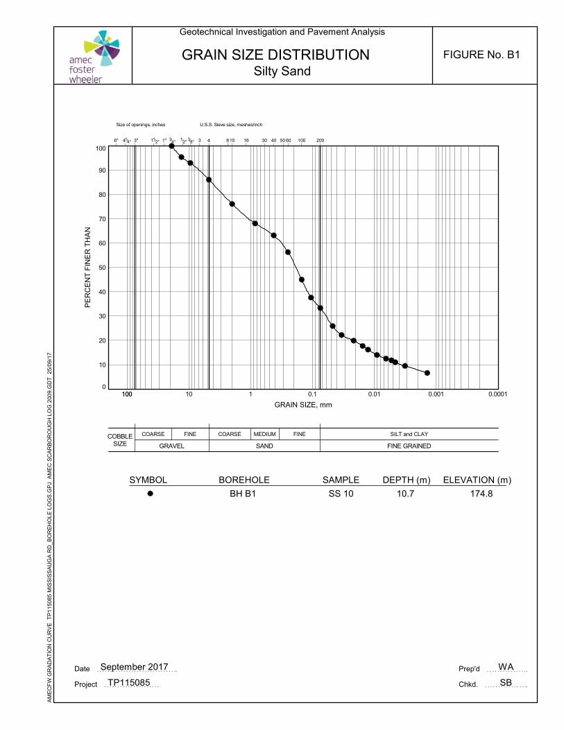
0
10
20
30
40
50
60
70
80
90
100
COBBLESIZE
COARSE MEDIUM FINE
3/8"
U.S.S. Sieve size, meshes/inch
3 10 16 301/2"
SAND
SILT and CLAY
FINE GRAINED
Size of openings, inches
6" 41/4"
1 0.1 0.01 0.001 0.0001100
40 50 60 1004" 2004
FINE
GRAVEL
COARSE
11/2" 1" 3/3" 8
PE
RC
EN
T F
INE
R T
HA
N
GRAIN SIZE, mm
100 10
GRAIN SIZE DISTRIBUTION
WA
SB
ELEVATION (m)
174.8
DEPTH (m)
10.7
SAMPLE
SS 10
SYMBOL
Date September 2017 Prep'd
Chkd.Project TP115085
Geotechnical Investigation and Pavement Analysis
Silty Sand
AM
EC
FW
GR
AD
AT
ION
CU
RV
E T
P11
5085
MIS
SIS
SA
UG
A R
D_B
OR
EH
OLE
LO
GS
.GP
J A
ME
C S
CA
RB
OR
OU
GH
LO
G 2
009.
GD
T
25/0
9/1
7
BOREHOLE
BH B1
FIGURE No. B1
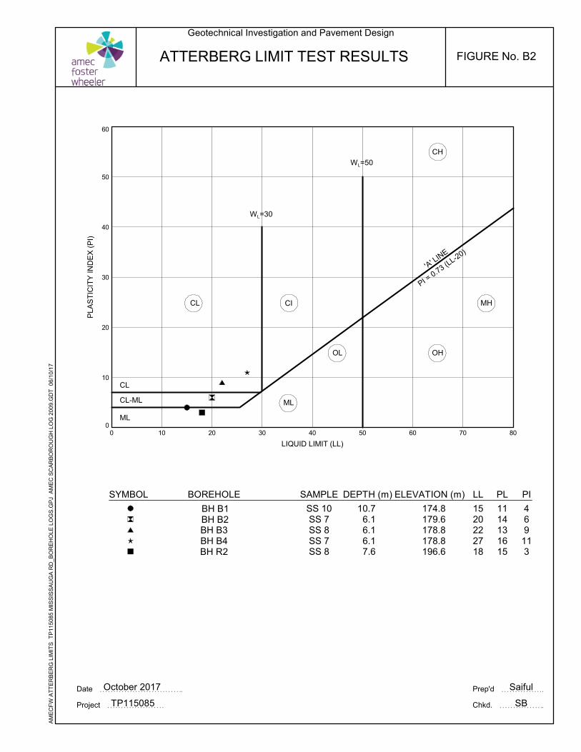
0
10
20
30
40
50
60
0 10 20 30 40 50 60 70 80
CICL MH
OHOL
ML
CL
CL-ML
ML
'A' LIN
E
CH
Saiful
SB
WL=50
WL=30
LIQUID LIMIT (LL)
PLA
ST
ICIT
Y IN
DE
X (
PI)
PI = 0.73 (L
L-20)
ATTERBERG LIMIT TEST RESULTS
SYMBOL PI
469
113
PL
1114131615
LL
1520222718
ELEVATION (m)
174.8179.6178.8178.8196.6
SAMPLE
SS 10SS 7SS 8SS 7SS 8
DEPTH (m)
10.76.16.16.17.6
BOREHOLE
Date October 2017 Prep'd
Chkd.Project TP115085
Geotechnical Investigation and Pavement Design
AM
EC
FW
AT
TE
RB
ER
G L
IMIT
S T
P11
5085
MIS
SIS
SA
UG
A R
D_B
OR
EH
OLE
LO
GS
.GP
J A
ME
C S
CA
RB
OR
OU
GH
LO
G 2
009.
GD
T
06/1
0/17
BH B1BH B2BH B3BH B4BH R2
FIGURE No. B2
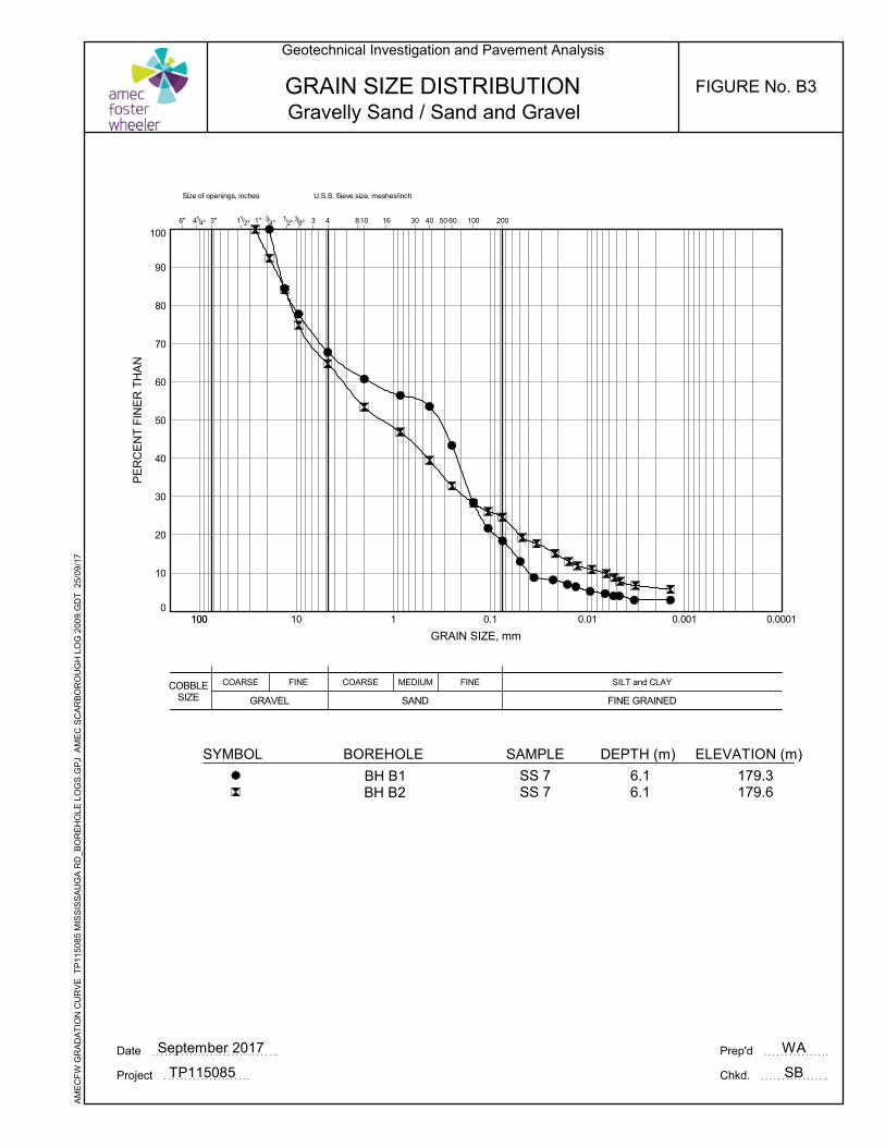
0
10
20
30
40
50
60
70
80
90
100
COBBLESIZE
COARSE MEDIUM FINE
3/8"
U.S.S. Sieve size, meshes/inch
3 10 16 301/2"
SAND
SILT and CLAY
FINE GRAINED
Size of openings, inches
6" 41/4"
1 0.1 0.01 0.001 0.0001100
40 50 60 1004" 2004
FINE
GRAVEL
COARSE
11/2" 1" 3/3" 8
PE
RC
EN
T F
INE
R T
HA
N
GRAIN SIZE, mm
100 10
GRAIN SIZE DISTRIBUTION
WA
SB
ELEVATION (m)
179.3179.6
DEPTH (m)
6.16.1
SAMPLE
SS 7SS 7
BOREHOLESYMBOL
Date September 2017 Prep'd
Chkd.Project TP115085
Geotechnical Investigation and Pavement Analysis
AM
EC
FW
GR
AD
AT
ION
CU
RV
E T
P11
5085
MIS
SIS
SA
UG
A R
D_B
OR
EH
OLE
LO
GS
.GP
J A
ME
C S
CA
RB
OR
OU
GH
LO
G 2
009.
GD
T
25/0
9/1
7
Gravelly Sand / Sand and Gravel
BH B1BH B2
FIGURE No. B3
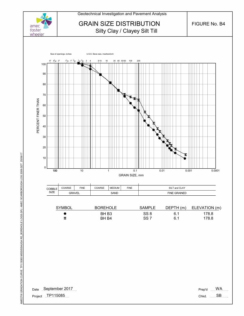
0
10
20
30
40
50
60
70
80
90
100
COBBLESIZE
COARSE MEDIUM FINE
3/8"
U.S.S. Sieve size, meshes/inch
3 10 16 301/2"
SAND
SILT and CLAY
FINE GRAINED
Size of openings, inches
6" 41/4"
1 0.1 0.01 0.001 0.0001100
40 50 60 1004" 2004
FINE
GRAVEL
COARSE
11/2" 1" 3/3" 8
PE
RC
EN
T F
INE
R T
HA
N
GRAIN SIZE, mm
100 10
GRAIN SIZE DISTRIBUTION
WA
SB
ELEVATION (m)
178.8178.8
DEPTH (m)
6.16.1
SAMPLE
SS 8SS 7
BOREHOLESYMBOL
Date September 2017 Prep'd
Chkd.Project TP115085
Geotechnical Investigation and Pavement Analysis
AM
EC
FW
GR
AD
AT
ION
CU
RV
E T
P11
5085
MIS
SIS
SA
UG
A R
D_B
OR
EH
OLE
LO
GS
.GP
J A
ME
C S
CA
RB
OR
OU
GH
LO
G 2
009.
GD
T
25/0
9/1
7
Silty Clay / Clayey Silt Till
BH B3BH B4
FIGURE No. B4
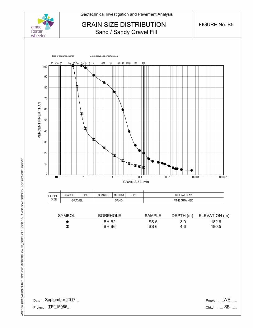
0
10
20
30
40
50
60
70
80
90
100
COBBLESIZE
COARSE MEDIUM FINE
3/8"
U.S.S. Sieve size, meshes/inch
3 10 16 301/2"
SAND
SILT and CLAY
FINE GRAINED
Size of openings, inches
6" 41/4"
1 0.1 0.01 0.001 0.0001100
40 50 60 1004" 2004
FINE
GRAVEL
COARSE
11/2" 1" 3/3" 8
PE
RC
EN
T F
INE
R T
HA
N
GRAIN SIZE, mm
100 10
GRAIN SIZE DISTRIBUTION
WA
SB
ELEVATION (m)
182.6180.5
DEPTH (m)
3.04.6
SAMPLE
SS 5SS 6
BOREHOLE
BH B2BH B6
SYMBOL
Date September 2017 Prep'd
Chkd.Project TP115085
Geotechnical Investigation and Pavement Analysis
AM
EC
FW
GR
AD
AT
ION
CU
RV
E T
P11
5085
MIS
SIS
SA
UG
A R
D_B
OR
EH
OLE
LO
GS
.GP
J A
ME
C S
CA
RB
OR
OU
GH
LO
G 2
009.
GD
T
25/0
9/1
7
Sand / Sandy Gravel FillFIGURE No. B5
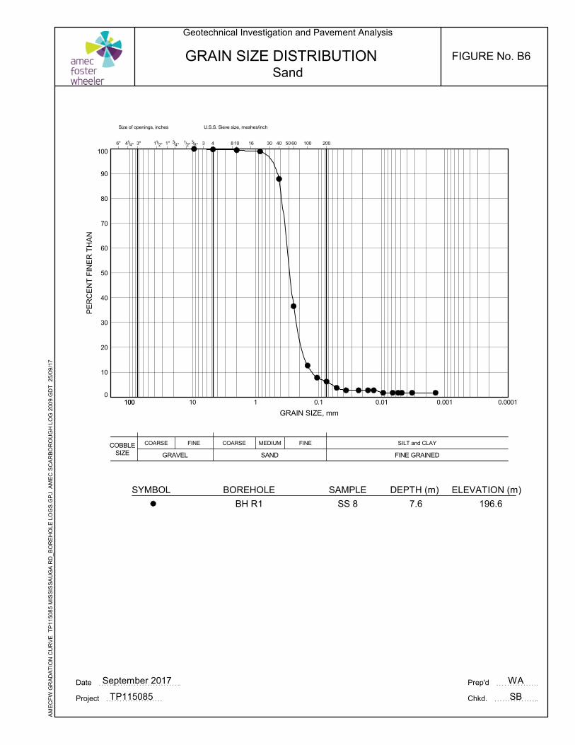
0
10
20
30
40
50
60
70
80
90
100
COBBLESIZE
COARSE MEDIUM FINE
3/8"
U.S.S. Sieve size, meshes/inch
3 10 16 301/2"
SAND
SILT and CLAY
FINE GRAINED
Size of openings, inches
6" 41/4"
1 0.1 0.01 0.001 0.0001100
40 50 60 1004" 2004
FINE
GRAVEL
COARSE
11/2" 1" 3/3" 8
PE
RC
EN
T F
INE
R T
HA
N
GRAIN SIZE, mm
100 10
GRAIN SIZE DISTRIBUTION
WA
SB
ELEVATION (m)
196.6
DEPTH (m)
7.6
SAMPLE
SS 8
SYMBOL
Date September 2017 Prep'd
Chkd.Project TP115085
Geotechnical Investigation and Pavement Analysis
Sand
AM
EC
FW
GR
AD
AT
ION
CU
RV
E T
P11
5085
MIS
SIS
SA
UG
A R
D_B
OR
EH
OLE
LO
GS
.GP
J A
ME
C S
CA
RB
OR
OU
GH
LO
G 2
009.
GD
T
25/0
9/1
7
BOREHOLE
BH R1
FIGURE No. B6
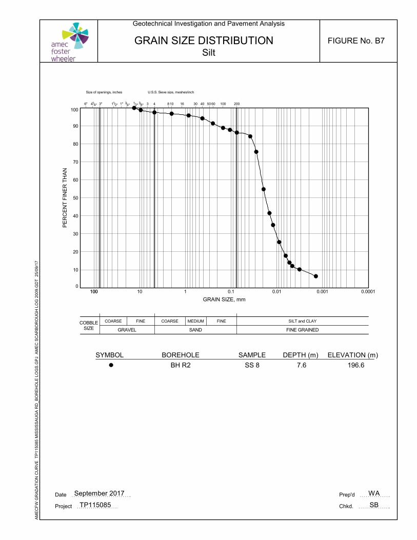
0
10
20
30
40
50
60
70
80
90
100
COBBLESIZE
COARSE MEDIUM FINE
3/8"
U.S.S. Sieve size, meshes/inch
3 10 16 301/2"
SAND
SILT and CLAY
FINE GRAINED
Size of openings, inches
6" 41/4"
1 0.1 0.01 0.001 0.0001100
40 50 60 1004" 2004
FINE
GRAVEL
COARSE
11/2" 1" 3/3" 8
PE
RC
EN
T F
INE
R T
HA
N
GRAIN SIZE, mm
100 10
GRAIN SIZE DISTRIBUTION
WA
SB
ELEVATION (m)
196.6
DEPTH (m)
7.6
SAMPLE
SS 8
BOREHOLE
BH R2
SYMBOL
Date September 2017 Prep'd
Chkd.Project TP115085
Geotechnical Investigation and Pavement Analysis
Silt
AM
EC
FW
GR
AD
AT
ION
CU
RV
E T
P11
5085
MIS
SIS
SA
UG
A R
D_B
OR
EH
OLE
LO
GS
.GP
J A
ME
C S
CA
RB
OR
OU
GH
LO
G 2
009.
GD
T
25/0
9/1
7FIGURE No. B7
APPENDIX CSOIL CHEMICAL ANALYSIS AND
CERTIFICATES OF ANALYSIS
CLIENT NAME: AMEC FOSTER WHEELER ENVIRO&INFRASTR104 CROCKFORD BLVDSCARBOROUGH, ON M1R3C3 (416) 751-6565
5835 COOPERS AVENUEMISSISSAUGA, ONTARIO
CANADA L4Z 1Y2TEL (905)712-5100FAX (905)712-5122
http://www.agatlabs.com
Yris Verastegui, Report ReviewerSOIL ANALYSIS REVIEWED BY:
Neli Popnikolova, Senior ChemistTRACE ORGANICS REVIEWED BY:
DATE REPORTED:
PAGES (INCLUDING COVER): 17
Jun 29, 2017
VERSION*: 1
Should you require any information regarding this analysis please contact your client services representative at (905) 712-5100
17T229179AGAT WORK ORDER:
ATTENTION TO: Shami Malla
PROJECT: Mississauga Road
Laboratories (V1) Page 1 of 17
All samples will be disposed of within 30 days following analysis. Please contact the lab if you require additional sample storage time.
AGAT Laboratories is accredited to ISO/IEC 17025 by the Canadian Association for Laboratory Accreditation Inc. (CALA) and/or Standards Council of Canada (SCC) for specific tests listed on the scope of accreditation. AGAT Laboratories (Mississauga) is also accredited by the Canadian Association for Laboratory Accreditation Inc. (CALA) for specific drinking water tests. Accreditations are location and parameter specific. A complete listing of parameters for each location is available from www.cala.ca and/or www.scc.ca. The tests in this report may not necessarily be included in the scope of accreditation.
Association of Professional Engineers and Geoscientists of Alberta (APEGA)Western Enviro-Agricultural Laboratory Association (WEALA)Environmental Services Association of Alberta (ESAA)
Member of:
*NOTES
Results relate only to the items tested and to all the items testedAll reportable information as specified by ISO 17025:2005 is available from AGAT Laboratories upon request
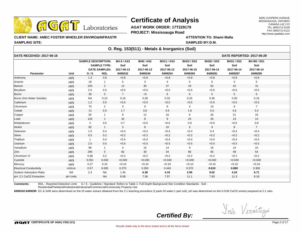
BH8 / AS2BH 6 / AS3 BH11 / AS3 BH23 / SS3 BH26 / SS3 BH31 / SS2 BH B6 / SS1SAMPLE DESCRIPTION:
SoilSoilSoil Soil Soil Soil SoilSAMPLE TYPE:
2017-06-142017-06-13 2017-06-13 2017-06-152017-06-13 2017-06-14 2017-06-14DATE SAMPLED:
8499242 8499249 8499254 8499260 8499281 8499287 8499295G / S RDLUnitParameter
<0.8 <0.8 <0.8 <0.8 <0.8 <0.8 <0.8Antimony 0.81.3µg/g
5 3 4 5 5 4 5Arsenic 118µg/g
12 30 37 19 62 42 31Barium 2220µg/g
<0.5 <0.5 <0.5 <0.5 <0.5 <0.5 <0.5Beryllium 0.52.5µg/g
7 <5 6 6 5 5 6Boron 536µg/g
0.16 0.28 0.32 0.25 0.36 0.30 0.16Boron (Hot Water Soluble) 0.10NAµg/g
<0.5 <0.5 <0.5 <0.5 <0.5 <0.5 <0.5Cadmium 0.51.2µg/g
3 9 9 4 10 9 7Chromium 270µg/g
1.7 3.8 4.9 1.8 5.0 4.6 3.4Cobalt 0.521µg/g
5 12 16 6 26 21 15Copper 192µg/g
32 8 9 24 26 13 14Lead 1120µg/g
0.7 <0.5 <0.5 0.9 <0.5 <0.5 0.8Molybdenum 0.52µg/g
3 8 10 5 9 8 7Nickel 182µg/g
<0.4 <0.4 <0.4 <0.4 0.4 <0.4 <0.4Selenium 0.41.5µg/g
<0.2 <0.2 <0.2 <0.2 <0.2 <0.2 <0.2Silver 0.20.5µg/g
<0.4 <0.4 <0.4 <0.4 <0.4 <0.4 <0.4Thallium 0.41µg/g
<0.5 <0.5 <0.5 <0.5 <0.5 <0.5 <0.5Uranium 0.52.5µg/g
4 15 14 9 16 14 15Vanadium 186µg/g
82 30 34 86 65 48 54Zinc 5290µg/g
<0.2 <0.2 <0.2 <0.2 <0.2 <0.2 <0.2Chromium VI 0.20.66µg/g
<0.040 <0.040 <0.040 <0.040 <0.040 <0.040 <0.040Cyanide 0.0400.051µg/g
<0.10 <0.10 <0.10 <0.10 <0.10 <0.10 <0.10Mercury 0.100.27µg/g
0.270 0.350 0.440 0.570 0.610 0.890 0.300Electrical Conductivity 0.0050.57mS/cm
1.45 6.38 4.16 2.95 9.62 4.24 6.71Sodium Adsorption Ratio NA2.4NA
8.08 7.36 7.57 11.1 7.83 11.3 8.18pH, 2:1 CaCl2 Extraction NApH Units
Comments: RDL - Reported Detection Limit; G / S - Guideline / Standard: Refers to Table 1: Full Depth Background Site Condition Standards - Soil - Residential/Parkland/Institutional/Industrial/Commercial/Community Property Use
8499242-8499295 EC & SAR were determined on the DI water extract obtained from the 2:1 leaching procedure (2 parts DI water:1 part soil). pH was determined on the 0.01M CaCl2 extract prepared at 2:1 ratio.
Results relate only to the items tested and to all the items tested
DATE RECEIVED: 2017-06-16
Certificate of Analysis
ATTENTION TO: Shami Malla CLIENT NAME: AMEC FOSTER WHEELER ENVIRO&INFRASTR
AGAT WORK ORDER: 17T229179
DATE REPORTED: 2017-06-29
PROJECT: Mississauga Road
O. Reg. 153(511) - Metals & Inorganics (Soil)
SAMPLED BY:D.M.SAMPLING SITE:
5835 COOPERS AVENUEMISSISSAUGA, ONTARIO
CANADA L4Z 1Y2TEL (905)712-5100FAX (905)712-5122
http://www.agatlabs.com
CERTIFICATE OF ANALYSIS (V1)
Certified By:Page 2 of 17
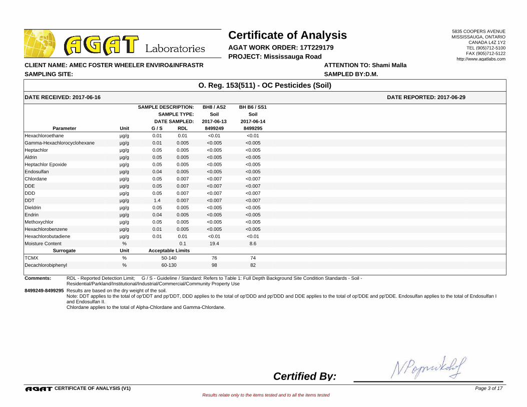
BH B6 / SS1BH8 / AS2SAMPLE DESCRIPTION:
SoilSoilSAMPLE TYPE:
2017-06-142017-06-13DATE SAMPLED:
8499249 8499295G / S RDLUnitParameter
<0.01 <0.01Hexachloroethane 0.010.01µg/g
<0.005 <0.005Gamma-Hexachlorocyclohexane 0.0050.01µg/g
<0.005 <0.005Heptachlor 0.0050.05µg/g
<0.005 <0.005Aldrin 0.0050.05µg/g
<0.005 <0.005Heptachlor Epoxide 0.0050.05µg/g
<0.005 <0.005Endosulfan 0.0050.04µg/g
<0.007 <0.007Chlordane 0.0070.05µg/g
<0.007 <0.007DDE 0.0070.05µg/g
<0.007 <0.007DDD 0.0070.05µg/g
<0.007 <0.007DDT 0.0071.4µg/g
<0.005 <0.005Dieldrin 0.0050.05µg/g
<0.005 <0.005Endrin 0.0050.04µg/g
<0.005 <0.005Methoxychlor 0.0050.05µg/g
<0.005 <0.005Hexachlorobenzene 0.0050.01µg/g
<0.01 <0.01Hexachlorobutadiene 0.010.01µg/g
19.4 8.6Moisture Content 0.1%
Acceptable LimitsUnitSurrogate
76 74TCMX % 50-140
98 82Decachlorobiphenyl % 60-130
Comments: RDL - Reported Detection Limit; G / S - Guideline / Standard: Refers to Table 1: Full Depth Background Site Condition Standards - Soil - Residential/Parkland/Institutional/Industrial/Commercial/Community Property Use
8499249-8499295 Results are based on the dry weight of the soil.Note: DDT applies to the total of op'DDT and pp'DDT, DDD applies to the total of op'DDD and pp'DDD and DDE applies to the total of op'DDE and pp'DDE. Endosulfan applies to the total of Endosulfan I and Endosulfan II.Chlordane applies to the total of Alpha-Chlordane and Gamma-Chlordane.
Results relate only to the items tested and to all the items tested
DATE RECEIVED: 2017-06-16
Certificate of Analysis
ATTENTION TO: Shami Malla CLIENT NAME: AMEC FOSTER WHEELER ENVIRO&INFRASTR
AGAT WORK ORDER: 17T229179
DATE REPORTED: 2017-06-29
PROJECT: Mississauga Road
O. Reg. 153(511) - OC Pesticides (Soil)
SAMPLED BY:D.M.SAMPLING SITE:
5835 COOPERS AVENUEMISSISSAUGA, ONTARIO
CANADA L4Z 1Y2TEL (905)712-5100FAX (905)712-5122
http://www.agatlabs.com
CERTIFICATE OF ANALYSIS (V1)
Certified By:Page 3 of 17
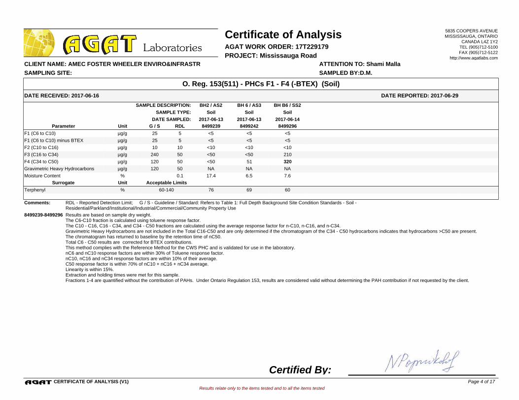
BH 6 / AS3BH2 / AS2 BH B6 / SS2SAMPLE DESCRIPTION:
SoilSoilSoilSAMPLE TYPE:
2017-06-13 2017-06-142017-06-13DATE SAMPLED:
8499239 8499242 8499296G / S RDLUnitParameter
<5 <5 <5F1 (C6 to C10) 525µg/g
<5 <5 <5F1 (C6 to C10) minus BTEX 525µg/g
<10 <10 <10F2 (C10 to C16) 1010µg/g
<50 <50 210F3 (C16 to C34) 50240µg/g
<50 51 320F4 (C34 to C50) 50120µg/g
NA NA NAGravimetric Heavy Hydrocarbons 50120µg/g
17.4 6.5 7.6Moisture Content 0.1%
Acceptable LimitsUnitSurrogate
76 69 60Terphenyl % 60-140
Comments: RDL - Reported Detection Limit; G / S - Guideline / Standard: Refers to Table 1: Full Depth Background Site Condition Standards - Soil - Residential/Parkland/Institutional/Industrial/Commercial/Community Property Use
8499239-8499296 Results are based on sample dry weight.The C6-C10 fraction is calculated using toluene response factor.The C10 - C16, C16 - C34, and C34 - C50 fractions are calculated using the average response factor for n-C10, n-C16, and n-C34.Gravimetric Heavy Hydrocarbons are not included in the Total C16-C50 and are only determined if the chromatogram of the C34 - C50 hydrocarbons indicates that hydrocarbons >C50 are present.The chromatogram has returned to baseline by the retention time of nC50.Total C6 - C50 results are corrected for BTEX contributions.This method complies with the Reference Method for the CWS PHC and is validated for use in the laboratory.nC6 and nC10 response factors are within 30% of Toluene response factor.nC10, nC16 and nC34 response factors are within 10% of their average.C50 response factor is within 70% of nC10 + nC16 + nC34 average.Linearity is within 15%.Extraction and holding times were met for this sample.Fractions 1-4 are quantified without the contribution of PAHs. Under Ontario Regulation 153, results are considered valid without determining the PAH contribution if not requested by the client.
Results relate only to the items tested and to all the items tested
DATE RECEIVED: 2017-06-16
Certificate of Analysis
ATTENTION TO: Shami Malla CLIENT NAME: AMEC FOSTER WHEELER ENVIRO&INFRASTR
AGAT WORK ORDER: 17T229179
DATE REPORTED: 2017-06-29
PROJECT: Mississauga Road
O. Reg. 153(511) - PHCs F1 - F4 (-BTEX) (Soil)
SAMPLED BY:D.M.SAMPLING SITE:
5835 COOPERS AVENUEMISSISSAUGA, ONTARIO
CANADA L4Z 1Y2TEL (905)712-5100FAX (905)712-5122
http://www.agatlabs.com
CERTIFICATE OF ANALYSIS (V1)
Certified By:Page 4 of 17
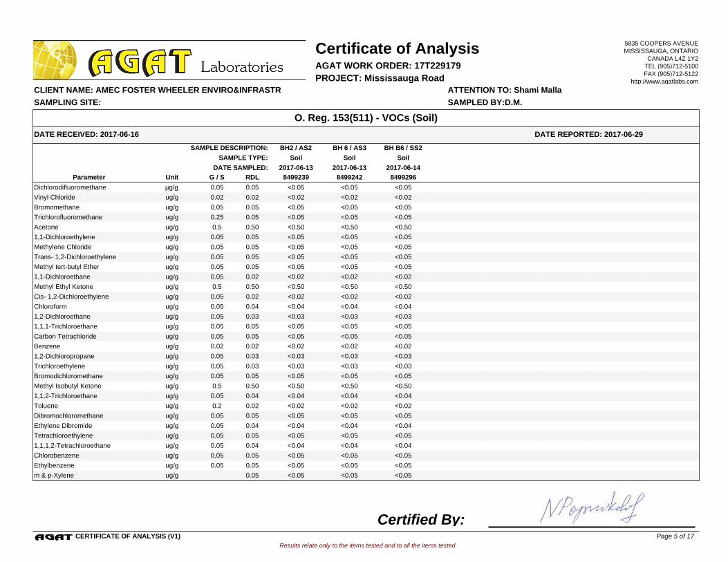
BH 6 / AS3BH2 / AS2 BH B6 / SS2SAMPLE DESCRIPTION:
SoilSoilSoilSAMPLE TYPE:
2017-06-13 2017-06-142017-06-13DATE SAMPLED:
8499239 8499242 8499296G / S RDLUnitParameter
<0.05 <0.05 <0.05Dichlorodifluoromethane 0.050.05µg/g
<0.02 <0.02 <0.02Vinyl Chloride 0.020.02ug/g
<0.05 <0.05 <0.05Bromomethane 0.050.05ug/g
<0.05 <0.05 <0.05Trichlorofluoromethane 0.050.25ug/g
<0.50 <0.50 <0.50Acetone 0.500.5ug/g
<0.05 <0.05 <0.051,1-Dichloroethylene 0.050.05ug/g
<0.05 <0.05 <0.05Methylene Chloride 0.050.05ug/g
<0.05 <0.05 <0.05Trans- 1,2-Dichloroethylene 0.050.05ug/g
<0.05 <0.05 <0.05Methyl tert-butyl Ether 0.050.05ug/g
<0.02 <0.02 <0.021,1-Dichloroethane 0.020.05ug/g
<0.50 <0.50 <0.50Methyl Ethyl Ketone 0.500.5ug/g
<0.02 <0.02 <0.02Cis- 1,2-Dichloroethylene 0.020.05ug/g
<0.04 <0.04 <0.04Chloroform 0.040.05ug/g
<0.03 <0.03 <0.031,2-Dichloroethane 0.030.05ug/g
<0.05 <0.05 <0.051,1,1-Trichloroethane 0.050.05ug/g
<0.05 <0.05 <0.05Carbon Tetrachloride 0.050.05ug/g
<0.02 <0.02 <0.02Benzene 0.020.02ug/g
<0.03 <0.03 <0.031,2-Dichloropropane 0.030.05ug/g
<0.03 <0.03 <0.03Trichloroethylene 0.030.05ug/g
<0.05 <0.05 <0.05Bromodichloromethane 0.050.05ug/g
<0.50 <0.50 <0.50Methyl Isobutyl Ketone 0.500.5ug/g
<0.04 <0.04 <0.041,1,2-Trichloroethane 0.040.05ug/g
<0.02 <0.02 <0.02Toluene 0.020.2ug/g
<0.05 <0.05 <0.05Dibromochloromethane 0.050.05ug/g
<0.04 <0.04 <0.04Ethylene Dibromide 0.040.05ug/g
<0.05 <0.05 <0.05Tetrachloroethylene 0.050.05ug/g
<0.04 <0.04 <0.041,1,1,2-Tetrachloroethane 0.040.05ug/g
<0.05 <0.05 <0.05Chlorobenzene 0.050.05ug/g
<0.05 <0.05 <0.05Ethylbenzene 0.050.05ug/g
<0.05 <0.05 <0.05m & p-Xylene 0.05ug/g
Results relate only to the items tested and to all the items tested
DATE RECEIVED: 2017-06-16
Certificate of Analysis
ATTENTION TO: Shami Malla CLIENT NAME: AMEC FOSTER WHEELER ENVIRO&INFRASTR
AGAT WORK ORDER: 17T229179
DATE REPORTED: 2017-06-29
PROJECT: Mississauga Road
O. Reg. 153(511) - VOCs (Soil)
SAMPLED BY:D.M.SAMPLING SITE:
5835 COOPERS AVENUEMISSISSAUGA, ONTARIO
CANADA L4Z 1Y2TEL (905)712-5100FAX (905)712-5122
http://www.agatlabs.com
CERTIFICATE OF ANALYSIS (V1)
Certified By:Page 5 of 17
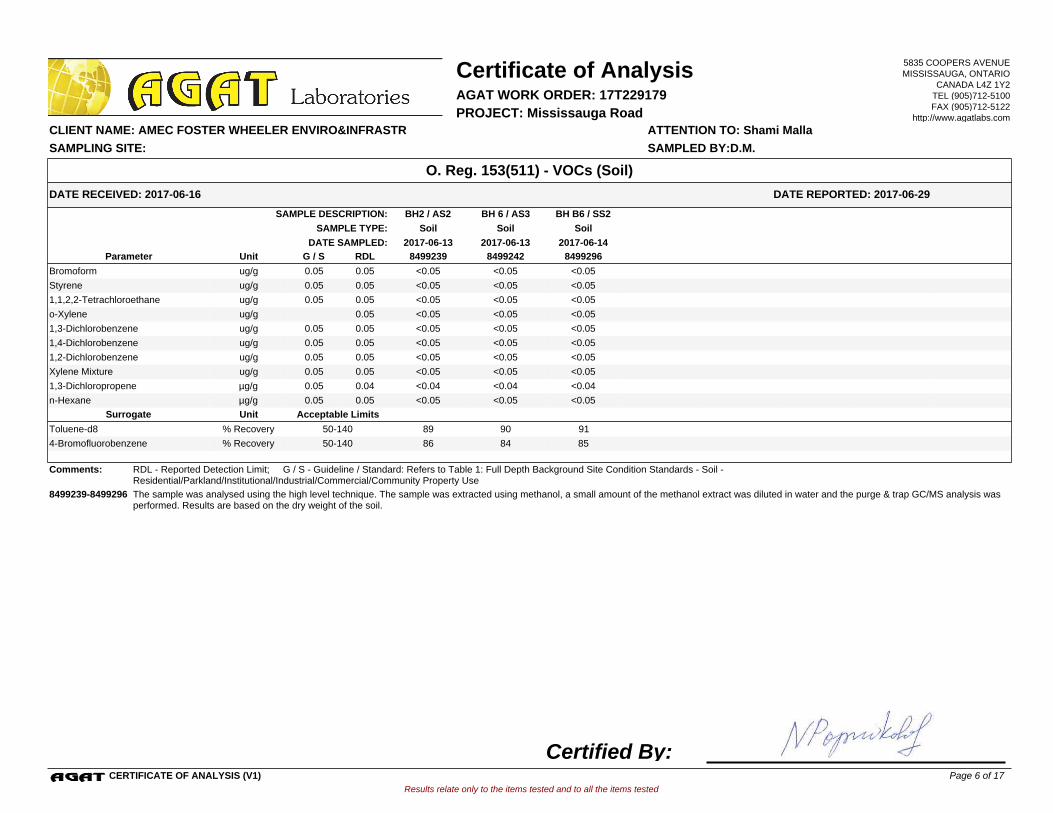
BH 6 / AS3BH2 / AS2 BH B6 / SS2SAMPLE DESCRIPTION:
SoilSoilSoilSAMPLE TYPE:
2017-06-13 2017-06-142017-06-13DATE SAMPLED:
8499239 8499242 8499296G / S RDLUnitParameter
<0.05 <0.05 <0.05Bromoform 0.050.05ug/g
<0.05 <0.05 <0.05Styrene 0.050.05ug/g
<0.05 <0.05 <0.051,1,2,2-Tetrachloroethane 0.050.05ug/g
<0.05 <0.05 <0.05o-Xylene 0.05ug/g
<0.05 <0.05 <0.051,3-Dichlorobenzene 0.050.05ug/g
<0.05 <0.05 <0.051,4-Dichlorobenzene 0.050.05ug/g
<0.05 <0.05 <0.051,2-Dichlorobenzene 0.050.05ug/g
<0.05 <0.05 <0.05Xylene Mixture 0.050.05ug/g
<0.04 <0.04 <0.041,3-Dichloropropene 0.040.05µg/g
<0.05 <0.05 <0.05n-Hexane 0.050.05µg/g
Acceptable LimitsUnitSurrogate
89 90 91Toluene-d8 % Recovery 50-140
86 84 854-Bromofluorobenzene % Recovery 50-140
Comments: RDL - Reported Detection Limit; G / S - Guideline / Standard: Refers to Table 1: Full Depth Background Site Condition Standards - Soil - Residential/Parkland/Institutional/Industrial/Commercial/Community Property Use
8499239-8499296 The sample was analysed using the high level technique. The sample was extracted using methanol, a small amount of the methanol extract was diluted in water and the purge & trap GC/MS analysis was performed. Results are based on the dry weight of the soil.
Results relate only to the items tested and to all the items tested
DATE RECEIVED: 2017-06-16
Certificate of Analysis
ATTENTION TO: Shami Malla CLIENT NAME: AMEC FOSTER WHEELER ENVIRO&INFRASTR
AGAT WORK ORDER: 17T229179
DATE REPORTED: 2017-06-29
PROJECT: Mississauga Road
O. Reg. 153(511) - VOCs (Soil)
SAMPLED BY:D.M.SAMPLING SITE:
5835 COOPERS AVENUEMISSISSAUGA, ONTARIO
CANADA L4Z 1Y2TEL (905)712-5100FAX (905)712-5122
http://www.agatlabs.com
CERTIFICATE OF ANALYSIS (V1)
Certified By:Page 6 of 17
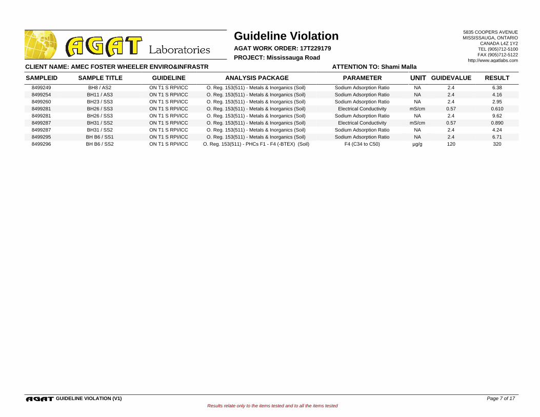
8499249 ON T1 S RPI/ICC O. Reg. 153(511) - Metals & Inorganics (Soil) Sodium Adsorption Ratio 2.4 6.38BH8 / AS2 NA
8499254 ON T1 S RPI/ICC O. Reg. 153(511) - Metals & Inorganics (Soil) Sodium Adsorption Ratio 2.4 4.16BH11 / AS3 NA
8499260 ON T1 S RPI/ICC O. Reg. 153(511) - Metals & Inorganics (Soil) Sodium Adsorption Ratio 2.4 2.95BH23 / SS3 NA
8499281 ON T1 S RPI/ICC O. Reg. 153(511) - Metals & Inorganics (Soil) Electrical Conductivity 0.57 0.610BH26 / SS3 mS/cm
8499281 ON T1 S RPI/ICC O. Reg. 153(511) - Metals & Inorganics (Soil) Sodium Adsorption Ratio 2.4 9.62BH26 / SS3 NA
8499287 ON T1 S RPI/ICC O. Reg. 153(511) - Metals & Inorganics (Soil) Electrical Conductivity 0.57 0.890BH31 / SS2 mS/cm
8499287 ON T1 S RPI/ICC O. Reg. 153(511) - Metals & Inorganics (Soil) Sodium Adsorption Ratio 2.4 4.24BH31 / SS2 NA
8499295 ON T1 S RPI/ICC O. Reg. 153(511) - Metals & Inorganics (Soil) Sodium Adsorption Ratio 2.4 6.71BH B6 / SS1 NA
8499296 ON T1 S RPI/ICC O. Reg. 153(511) - PHCs F1 - F4 (-BTEX) (Soil) F4 (C34 to C50) 120 320BH B6 / SS2 µg/g
Results relate only to the items tested and to all the items tested
Guideline Violation
ATTENTION TO: Shami Malla CLIENT NAME: AMEC FOSTER WHEELER ENVIRO&INFRASTR
AGAT WORK ORDER: 17T229179
PROJECT: Mississauga Road
SAMPLEID GUIDELINE ANALYSIS PACKAGE PARAMETER GUIDEVALUE RESULTSAMPLE TITLE UNIT
5835 COOPERS AVENUEMISSISSAUGA, ONTARIO
CANADA L4Z 1Y2TEL (905)712-5100FAX (905)712-5122
http://www.agatlabs.com
GUIDELINE VIOLATION (V1) Page 7 of 17

O. Reg. 153(511) - Metals & Inorganics (Soil)
Antimony 8499295 8499295 <0.8 <0.8 NA < 0.8 102% 70% 130% 109% 80% 120% 73% 70% 130%
Arsenic 8499295 8499295 5 5 0.0% < 1 114% 70% 130% 112% 80% 120% 94% 70% 130%
Barium 8499295 8499295 31 32 3.2% < 2 106% 70% 130% 112% 80% 120% 99% 70% 130%
Beryllium 8499295 8499295 <0.5 <0.5 NA < 0.5 79% 70% 130% 108% 80% 120% 74% 70% 130%
Boron
8499295 8499295 6 6 NA < 5 109% 70% 130% 104% 80% 120% 74% 70% 130%
Boron (Hot Water Soluble) 8499295 8499295 0.16 0.16 NA < 0.10 109% 60% 140% 101% 70% 130% 92% 60% 140%
Cadmium 8499295 8499295 <0.5 <0.5 NA < 0.5 93% 70% 130% 108% 80% 120% 91% 70% 130%
Chromium 8499295 8499295 7 7 NA < 2 77% 70% 130% 107% 80% 120% 81% 70% 130%
Cobalt 8499295 8499295 3.4 3.5 2.9% < 0.5 89% 70% 130% 118% 80% 120% 86% 70% 130%
Copper
8499295 8499295 15 16 6.5% < 1 78% 70% 130% 105% 80% 120% 72% 70% 130%
Lead 8499295 8499295 14 13 7.4% < 1 102% 70% 130% 111% 80% 120% 85% 70% 130%
Molybdenum 8499295 8499295 0.8 0.8 NA < 0.5 94% 70% 130% 113% 80% 120% 94% 70% 130%
Nickel 8499295 8499295 7 8 13.3% < 1 85% 70% 130% 112% 80% 120% 78% 70% 130%
Selenium 8499295 8499295 <0.4 <0.4 NA < 0.4 125% 70% 130% 109% 80% 120% 93% 70% 130%
Silver
8499295 8499295 <0.2 <0.2 NA < 0.2 98% 70% 130% 117% 80% 120% 89% 70% 130%
Thallium 8499295 8499295 <0.4 <0.4 NA < 0.4 116% 70% 130% 113% 80% 120% 93% 70% 130%
Uranium 8499295 8499295 <0.5 <0.5 NA < 0.5 94% 70% 130% 114% 80% 120% 99% 70% 130%
Vanadium 8499295 8499295 15 15 0.0% < 1 78% 70% 130% 102% 80% 120% 79% 70% 130%
Zinc 8499295 8499295 54 51 5.7% < 5 102% 70% 130% 114% 80% 120% 97% 70% 130%
Chromium VI
8499315 <0.2 <0.2 NA < 0.2 92% 70% 130% 103% 80% 120% 102% 70% 130%
Cyanide 8496633 <0.040 <0.040 NA < 0.040 90% 70% 130% 106% 80% 120% 101% 70% 130%
Mercury 8499295 8499295 <0.10 <0.10 NA < 0.10 100% 70% 130% 101% 80% 120% 87% 70% 130%
Electrical Conductivity 8499295 8499295 0.300 0.300 0.0% < 0.005 95% 90% 110% NA NA
Sodium Adsorption Ratio 8499295 8499295 6.71 6.19 8.1% NA NA NA NA
pH, 2:1 CaCl2 Extraction
8499254 8499254 7.57 7.61 0.5% NA 101% 80% 120% NA NA
Comments: NA signifies Not Applicable.Duplicate Qualifier: As the measured result approaches the RL, the uncertainty associated with the value increases dramatically, thus duplicate acceptance limits apply only where the average of the two duplicates is greater than five times the RL.
Certified By:
Results relate only to the items tested and to all the items tested
SAMPLING SITE: SAMPLED BY:D.M.
AGAT WORK ORDER: 17T229179
Dup #1 RPDMeasured
ValueRecovery Recovery
Quality Assurance
ATTENTION TO: Shami Malla
CLIENT NAME: AMEC FOSTER WHEELER ENVIRO&INFRASTR
PROJECT: Mississauga Road
Soil Analysis
UpperLower
AcceptableLimits
BatchPARAMETERSample
IdDup #2
UpperLower
AcceptableLimits
UpperLower
AcceptableLimits
MATRIX SPIKEMETHOD BLANK SPIKEDUPLICATERPT Date: Jun 29, 2017 REFERENCE MATERIAL
MethodBlank
5835 COOPERS AVENUEMISSISSAUGA, ONTARIO
CANADA L4Z 1Y2TEL (905)712-5100FAX (905)712-5122
http://www.agatlabs.com
QUALITY ASSURANCE REPORT (V1) Page 8 of 17
AGAT Laboratories is accredited to ISO/IEC 17025 by the Canadian Association for Laboratory Accreditation Inc. (CALA) and/or Standards Council of Canada (SCC) for specific tests listed on the scope of accreditation. AGAT Laboratories (Mississauga) is also accredited by the Canadian Association for Laboratory Accreditation Inc. (CALA) for specific drinking water tests. Accreditations are location and parameter specific. A complete listing of parameters for each location is available from www.cala.ca and/or www.scc.ca. The tests in this report may not necessarily be included in the scope of accreditation.
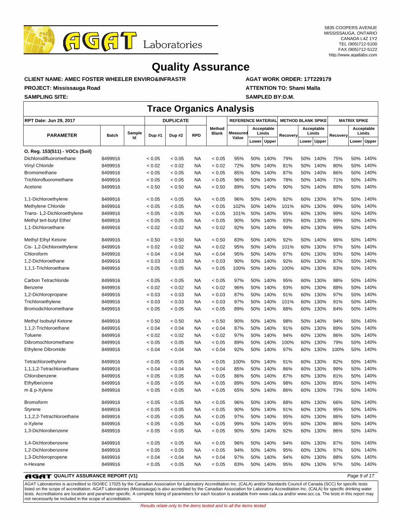
O. Reg. 153(511) - VOCs (Soil)
Dichlorodifluoromethane 8499916 < 0.05 < 0.05 NA < 0.05 95% 50% 140% 79% 50% 140% 75% 50% 140%
Vinyl Chloride 8499916 < 0.02 < 0.02 NA < 0.02 72% 50% 140% 81% 50% 140% 80% 50% 140%
Bromomethane 8499916 < 0.05 < 0.05 NA < 0.05 85% 50% 140% 87% 50% 140% 86% 50% 140%
Trichlorofluoromethane 8499916 < 0.05 < 0.05 NA < 0.05 96% 50% 140% 78% 50% 140% 71% 50% 140%
Acetone
8499916 < 0.50 < 0.50 NA < 0.50 89% 50% 140% 90% 50% 140% 89% 50% 140%
1,1-Dichloroethylene 8499916 < 0.05 < 0.05 NA < 0.05 96% 50% 140% 92% 60% 130% 97% 50% 140%
Methylene Chloride 8499916 < 0.05 < 0.05 NA < 0.05 102% 50% 140% 101% 60% 130% 99% 50% 140%
Trans- 1,2-Dichloroethylene 8499916 < 0.05 < 0.05 NA < 0.05 101% 50% 140% 95% 60% 130% 99% 50% 140%
Methyl tert-butyl Ether 8499916 < 0.05 < 0.05 NA < 0.05 90% 50% 140% 93% 60% 130% 99% 50% 140%
1,1-Dichloroethane
8499916 < 0.02 < 0.02 NA < 0.02 92% 50% 140% 99% 60% 130% 99% 50% 140%
Methyl Ethyl Ketone 8499916 < 0.50 < 0.50 NA < 0.50 83% 50% 140% 92% 50% 140% 96% 50% 140%
Cis- 1,2-Dichloroethylene 8499916 < 0.02 < 0.02 NA < 0.02 95% 50% 140% 101% 60% 130% 97% 50% 140%
Chloroform 8499916 < 0.04 < 0.04 NA < 0.04 95% 50% 140% 97% 60% 130% 93% 50% 140%
1,2-Dichloroethane 8499916 < 0.03 < 0.03 NA < 0.03 90% 50% 140% 92% 60% 130% 87% 50% 140%
1,1,1-Trichloroethane
8499916 < 0.05 < 0.05 NA < 0.05 100% 50% 140% 100% 60% 130% 93% 50% 140%
Carbon Tetrachloride 8499916 < 0.05 < 0.05 NA < 0.05 97% 50% 140% 95% 60% 130% 98% 50% 140%
Benzene 8499916 < 0.02 < 0.02 NA < 0.02 96% 50% 140% 93% 60% 130% 88% 50% 140%
1,2-Dichloropropane 8499916 < 0.03 < 0.03 NA < 0.03 87% 50% 140% 91% 60% 130% 97% 50% 140%
Trichloroethylene 8499916 < 0.03 < 0.03 NA < 0.03 97% 50% 140% 101% 60% 130% 91% 50% 140%
Bromodichloromethane
8499916 < 0.05 < 0.05 NA < 0.05 89% 50% 140% 88% 60% 130% 84% 50% 140%
Methyl Isobutyl Ketone 8499916 < 0.50 < 0.50 NA < 0.50 90% 50% 140% 98% 50% 140% 94% 50% 140%
1,1,2-Trichloroethane 8499916 < 0.04 < 0.04 NA < 0.04 87% 50% 140% 91% 60% 130% 89% 50% 140%
Toluene 8499916 < 0.02 < 0.02 NA < 0.02 97% 50% 140% 94% 60% 130% 86% 50% 140%
Dibromochloromethane 8499916 < 0.05 < 0.05 NA < 0.05 89% 50% 140% 100% 60% 130% 79% 50% 140%
Ethylene Dibromide
8499916 < 0.04 < 0.04 NA < 0.04 92% 50% 140% 97% 60% 130% 100% 50% 140%
Tetrachloroethylene 8499916 < 0.05 < 0.05 NA < 0.05 100% 50% 140% 91% 60% 130% 82% 50% 140%
1,1,1,2-Tetrachloroethane 8499916 < 0.04 < 0.04 NA < 0.04 85% 50% 140% 86% 60% 130% 99% 50% 140%
Chlorobenzene 8499916 < 0.05 < 0.05 NA < 0.05 86% 50% 140% 87% 60% 130% 81% 50% 140%
Ethylbenzene 8499916 < 0.05 < 0.05 NA < 0.05 89% 50% 140% 98% 60% 130% 85% 50% 140%
m & p-Xylene
8499916 < 0.05 < 0.05 NA < 0.05 65% 50% 140% 86% 60% 130% 73% 50% 140%
Bromoform 8499916 < 0.05 < 0.05 NA < 0.05 96% 50% 140% 88% 60% 130% 66% 50% 140%
Styrene 8499916 < 0.05 < 0.05 NA < 0.05 90% 50% 140% 91% 60% 130% 95% 50% 140%
1,1,2,2-Tetrachloroethane 8499916 < 0.05 < 0.05 NA < 0.05 97% 50% 140% 95% 60% 130% 86% 50% 140%
o-Xylene 8499916 < 0.05 < 0.05 NA < 0.05 99% 50% 140% 95% 60% 130% 86% 50% 140%
1,3-Dichlorobenzene
8499916 < 0.05 < 0.05 NA < 0.05 90% 50% 140% 92% 60% 130% 86% 50% 140%
1,4-Dichlorobenzene 8499916 < 0.05 < 0.05 NA < 0.05 96% 50% 140% 94% 60% 130% 87% 50% 140%
1,2-Dichlorobenzene 8499916 < 0.05 < 0.05 NA < 0.05 94% 50% 140% 95% 60% 130% 97% 50% 140%
1,3-Dichloropropene 8499916 < 0.04 < 0.04 NA < 0.04 97% 50% 140% 94% 60% 130% 88% 50% 140%
n-Hexane 8499916 < 0.05 < 0.05 NA < 0.05 83% 50% 140% 95% 60% 130% 97% 50% 140%
Results relate only to the items tested and to all the items tested
SAMPLING SITE: SAMPLED BY:D.M.
AGAT WORK ORDER: 17T229179
Dup #1 RPDMeasured
ValueRecovery Recovery
Quality Assurance
ATTENTION TO: Shami Malla
CLIENT NAME: AMEC FOSTER WHEELER ENVIRO&INFRASTR
PROJECT: Mississauga Road
Trace Organics Analysis
UpperLower
AcceptableLimits
BatchPARAMETERSample
IdDup #2
UpperLower
AcceptableLimits
UpperLower
AcceptableLimits
MATRIX SPIKEMETHOD BLANK SPIKEDUPLICATERPT Date: Jun 29, 2017 REFERENCE MATERIAL
MethodBlank
5835 COOPERS AVENUEMISSISSAUGA, ONTARIO
CANADA L4Z 1Y2TEL (905)712-5100FAX (905)712-5122
http://www.agatlabs.com
QUALITY ASSURANCE REPORT (V1) Page 9 of 17
AGAT Laboratories is accredited to ISO/IEC 17025 by the Canadian Association for Laboratory Accreditation Inc. (CALA) and/or Standards Council of Canada (SCC) for specific tests listed on the scope of accreditation. AGAT Laboratories (Mississauga) is also accredited by the Canadian Association for Laboratory Accreditation Inc. (CALA) for specific drinking water tests. Accreditations are location and parameter specific. A complete listing of parameters for each location is available from www.cala.ca and/or www.scc.ca. The tests in this report may not necessarily be included in the scope of accreditation.
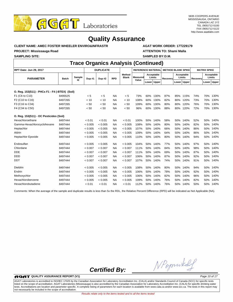
O. Reg. 153(511) - PHCs F1 - F4 (-BTEX) (Soil)
F1 (C6 to C10) 8495525 < 5 < 5 NA < 5 73% 60% 130% 87% 85% 115% 74% 70% 130%
F2 (C10 to C16) 8497265 < 10 < 10 NA < 10 108% 60% 130% 82% 80% 120% 73% 70% 130%
F3 (C16 to C34) 8497265 < 50 < 50 NA < 50 109% 60% 130% 80% 80% 120% 76% 70% 130%
F4 (C34 to C50) 8497265 < 50 < 50 NA < 50 96% 60% 130% 88% 80% 120% 72% 70% 130%
O. Reg. 153(511) - OC Pesticides (Soil)
Hexachloroethane 8497444 < 0.01 < 0.01 NA < 0.01 100% 50% 140% 58% 50% 140% 52% 50% 140%
Gamma-Hexachlorocyclohexane 8497444 < 0.005 < 0.005 NA < 0.005 108% 50% 140% 80% 50% 140% 82% 50% 140%
Heptachlor 8497444 < 0.005 < 0.005 NA < 0.005 107% 50% 140% 66% 50% 140% 86% 50% 140%
Aldrin 8497444 < 0.005 < 0.005 NA < 0.005 109% 50% 140% 64% 50% 140% 86% 50% 140%
Heptachlor Epoxide
8497444 < 0.005 < 0.005 NA < 0.005 110% 50% 140% 80% 50% 140% 94% 50% 140%
Endosulfan 8497444 < 0.005 < 0.005 NA < 0.005 104% 50% 140% 77% 50% 140% 97% 50% 140%
Chlordane 8497444 < 0.007 < 0.007 NA < 0.007 111% 50% 140% 84% 50% 140% 98% 50% 140%
DDE 8497444 < 0.007 < 0.007 NA < 0.007 111% 50% 140% 69% 50% 140% 87% 50% 140%
DDD 8497444 < 0.007 < 0.007 NA < 0.007 106% 50% 140% 87% 50% 140% 92% 50% 140%
DDT
8497444 < 0.007 < 0.007 NA < 0.007 107% 50% 140% 74% 50% 140% 91% 50% 140%
Dieldrin 8497444 < 0.005 < 0.005 NA < 0.005 108% 50% 140% 80% 50% 140% 94% 50% 140%
Endrin 8497444 < 0.005 < 0.005 NA < 0.005 106% 50% 140% 78% 50% 140% 92% 50% 140%
Methoxychlor 8497444 < 0.005 < 0.005 NA < 0.005 106% 50% 140% 82% 50% 140% 96% 50% 140%
Hexachlorobenzene 8497444 < 0.005 < 0.005 NA < 0.005 109% 50% 140% 76% 50% 140% 82% 50% 140%
Hexachlorobutadiene
8497444 < 0.01 < 0.01 NA < 0.01 112% 50% 140% 76% 50% 140% 50% 50% 140%
Comments: When the average of the sample and duplicate results is less than 5x the RDL, the Relative Percent Difference (RPD) will be indicated as Not Applicable (NA).
Certified By:
Results relate only to the items tested and to all the items tested
SAMPLING SITE: SAMPLED BY:D.M.
AGAT WORK ORDER: 17T229179
Dup #1 RPDMeasured
ValueRecovery Recovery
Quality Assurance
ATTENTION TO: Shami Malla
CLIENT NAME: AMEC FOSTER WHEELER ENVIRO&INFRASTR
PROJECT: Mississauga Road
Trace Organics Analysis (Continued)
UpperLower
AcceptableLimits
BatchPARAMETERSample
IdDup #2
UpperLower
AcceptableLimits
UpperLower
AcceptableLimits
MATRIX SPIKEMETHOD BLANK SPIKEDUPLICATERPT Date: Jun 29, 2017 REFERENCE MATERIAL
MethodBlank
5835 COOPERS AVENUEMISSISSAUGA, ONTARIO
CANADA L4Z 1Y2TEL (905)712-5100FAX (905)712-5122
http://www.agatlabs.com
QUALITY ASSURANCE REPORT (V1) Page 10 of 17
AGAT Laboratories is accredited to ISO/IEC 17025 by the Canadian Association for Laboratory Accreditation Inc. (CALA) and/or Standards Council of Canada (SCC) for specific tests listed on the scope of accreditation. AGAT Laboratories (Mississauga) is also accredited by the Canadian Association for Laboratory Accreditation Inc. (CALA) for specific drinking water tests. Accreditations are location and parameter specific. A complete listing of parameters for each location is available from www.cala.ca and/or www.scc.ca. The tests in this report may not necessarily be included in the scope of accreditation.
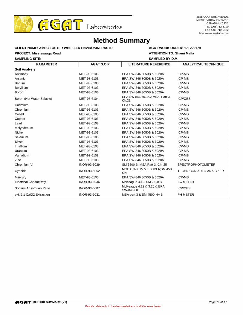
Soil Analysis
Antimony MET-93-6103 EPA SW-846 3050B & 6020A ICP-MS
Arsenic MET-93-6103 EPA SW-846 3050B & 6020A ICP-MS
Barium MET-93-6103 EPA SW-846 3050B & 6020A ICP-MS
Beryllium MET-93-6103 EPA SW-846 3050B & 6020A ICP-MS
Boron MET-93-6103 EPA SW-846 3050B & 6020A ICP-MS
Boron (Hot Water Soluble) MET-93-6104EPA SW 846 6010C; MSA, Part 3, Ch.21
ICP/OES
Cadmium MET-93-6103 EPA SW-846 3050B & 6020A ICP-MS
Chromium MET-93-6103 EPA SW-846 3050B & 6020A ICP-MS
Cobalt MET-93-6103 EPA SW-846 3050B & 6020A ICP-MS
Copper MET-93-6103 EPA SW-846 3050B & 6020A ICP-MS
Lead MET-93-6103 EPA SW-846 3050B & 6020A ICP-MS
Molybdenum MET-93-6103 EPA SW-846 3050B & 6020A ICP-MS
Nickel MET-93-6103 EPA SW-846 3050B & 6020A ICP-MS
Selenium MET-93-6103 EPA SW-846 3050B & 6020A ICP-MS
Silver MET-93-6103 EPA SW-846 3050B & 6020A ICP-MS
Thallium MET-93-6103 EPA SW-846 3050B & 6020A ICP-MS
Uranium MET-93-6103 EPA SW-846 3050B & 6020A ICP-MS
Vanadium MET-93-6103 EPA SW-846 3050B & 6020A ICP-MS
Zinc MET-93-6103 EPA SW-846 3050B & 6020A ICP-MS
Chromium VI INOR-93-6029 SM 3500 B; MSA Part 3, Ch. 25 SPECTROPHOTOMETER
Cyanide INOR-93-6052MOE CN-3015 & E 3009 A;SM 4500 CN
TECHNICON AUTO ANALYZER
Mercury MET-93-6103 EPA SW-846 3050B & 6020A ICP-MS
Electrical Conductivity INOR-93-6036 McKeague 4.12, SM 2510 B EC METER
Sodium Adsorption Ratio INOR-93-6007McKeague 4.12 & 3.26 & EPA SW-846 6010B
ICP/OES
pH, 2:1 CaCl2 Extraction INOR-93-6031 MSA part 3 & SM 4500-H+ B PH METER
Results relate only to the items tested and to all the items tested
SAMPLING SITE: SAMPLED BY:D.M.
AGAT WORK ORDER: 17T229179
Method Summary
ATTENTION TO: Shami Malla
CLIENT NAME: AMEC FOSTER WHEELER ENVIRO&INFRASTR
PROJECT: Mississauga Road
AGAT S.O.P ANALYTICAL TECHNIQUELITERATURE REFERENCEPARAMETER
5835 COOPERS AVENUEMISSISSAUGA, ONTARIO
CANADA L4Z 1Y2TEL (905)712-5100FAX (905)712-5122
http://www.agatlabs.com
METHOD SUMMARY (V1) Page 11 of 17

Trace Organics Analysis
Hexachloroethane ORG-91-5113 EPA SW-846 3541,3620 & 8081 GC/ECD
Gamma-Hexachlorocyclohexane ORG-91-5113 EPA SW-846 3541,3620 & 8081 GC/ECD
Heptachlor ORG-91-5113 EPA SW-846 3541,3620 & 8081 GC/ECD
Aldrin ORG-91-5113 EPA SW-846 3541,3620 & 8081 GC/ECD
Heptachlor Epoxide ORG-91-5113 EPA SW-846 3541,3620 & 8081 GC/ECD
Endosulfan ORG-91-5113 EPA SW-846 3541,3620 & 8081 GC/ECD
Chlordane ORG-91-5113 EPA SW-846 3541,3620 & 8081 GC/ECD
DDE ORG-91-5113 EPA SW-846 3541,3620 & 8081 GC/ECD
DDD ORG-91-5113 EPA SW-846 3541,3620 & 8081 GC/ECD
DDT ORG-91-5113 EPA SW-846 3541,3620 & 8081 GC/ECD
Dieldrin ORG-91-5113 EPA SW-846 3541,3620 & 8081 GC/ECD
Endrin ORG-91-5113 EPA SW-846 3541,3620 & 8081 GC/ECD
Methoxychlor ORG-91-5113 EPA SW-846 3541,3620 & 8081 GC/ECD
Hexachlorobenzene ORG-91-5113 EPA SW-846 3541,3620 & 8081 GC/ECD
Hexachlorobutadiene ORG-91-5113 EPA SW-846 3541,3620 & 8081 GC/ECD
TCMX ORG-91-5112 EPA SW-846 3541,3620 & 8081 GC/ECD
Decachlorobiphenyl ORG-91-5113 EPA SW-846 3541,3620 & 8081 GC/ECD
Moisture Content MOE E3139 BALANCE
F1 (C6 to C10) VOL-91-5009 CCME Tier 1 Method, SW846 5035 P &T GC / FID
F1 (C6 to C10) minus BTEX VOL-91-5009 CCME Tier 1 Method, SW846 5035 P & T GC / FID
F2 (C10 to C16) VOL-91-5009 CCME Tier 1 Method GC / FID
F3 (C16 to C34) VOL-91-5009 CCME Tier 1 Method GC / FID
F4 (C34 to C50) VOL-91-5009 CCME Tier 1 Method GC / FID
Gravimetric Heavy Hydrocarbons VOL-91-5009 CCME Tier 1 Method Balance
Moisture Content VOL-91-5009CCME Tier 1 Method, SW846 5035,8015
BALANCE
Terphenyl VOL-91-5009 CCME Tier 1 Method GC/FID
Dichlorodifluoromethane VOL-91-5002 EPA SW-846 5035 & 8260 (P&T)GC/MS
Vinyl Chloride VOL-91-5002 EPA SW-846 5035 & 8260 (P&T)GC/MS
Bromomethane VOL-91-5002 EPA SW-846 5035 & 8260 (P&T)GC/MS
Trichlorofluoromethane VOL-91-5002 EPA SW-846 5035 & 8260 (P&T)GC/MS
Acetone VOL-91-5002 EPA SW-846 5035 & 8260 (P&T)GC/MS
1,1-Dichloroethylene VOL-91-5002 EPA SW-846 5035 & 8260 (P&T)GC/MS
Methylene Chloride VOL-91-5002 EPA SW-846 5035 & 8260 (P&T)GC/MS
Trans- 1,2-Dichloroethylene VOL-91-5002 EPA SW-846 5035 & 8260 (P&T)GC/MS
Methyl tert-butyl Ether VOL-91-5002 EPA SW-846 5035 & 8260 (P&T)GC/MS
1,1-Dichloroethane VOL-91-5002 EPA SW-846 5035 & 8260 (P&T)GC/MS
Methyl Ethyl Ketone VOL-91-5002 EPA SW-846 5035 & 8260 (P&T)GC/MS
Cis- 1,2-Dichloroethylene VOL-91-5002 EPA SW-846 5035 & 8260 (P&T)GC/MS
Chloroform VOL-91-5002 EPA SW-846 5035 & 8260 (P&T)GC/MS
1,2-Dichloroethane VOL-91-5002 EPA SW-846 5035 & 8260 (P&T)GC/MS
1,1,1-Trichloroethane VOL-91-5002 EPA SW-846 5035 & 8260 (P&T)GC/MS
Carbon Tetrachloride VOL-91-5002 EPA SW-846 5035 & 8260 (P&T)GC/MS
Benzene VOL-91-5002 EPA SW-846 5035 & 8260 (P&T)GC/MS
1,2-Dichloropropane VOL-91-5002 EPA SW-846 5035 & 8260 (P&T)GC/MS
Trichloroethylene VOL-91-5002 EPA SW-846 5035 & 8260 (P&T)GC/MS
Bromodichloromethane VOL-91-5002 EPA SW-846 5035 & 8260 (P&T)GC/MS
Methyl Isobutyl Ketone VOL-91-5002 EPA SW-846 5035 & 8260 (P&T)GC/MS
1,1,2-Trichloroethane VOL-91-5002 EPA SW-846 5035 & 8260 (P&T)GC/MS
Results relate only to the items tested and to all the items tested
SAMPLING SITE: SAMPLED BY:D.M.
AGAT WORK ORDER: 17T229179
Method Summary
ATTENTION TO: Shami Malla
CLIENT NAME: AMEC FOSTER WHEELER ENVIRO&INFRASTR
PROJECT: Mississauga Road
AGAT S.O.P ANALYTICAL TECHNIQUELITERATURE REFERENCEPARAMETER
5835 COOPERS AVENUEMISSISSAUGA, ONTARIO
CANADA L4Z 1Y2TEL (905)712-5100FAX (905)712-5122
http://www.agatlabs.com
METHOD SUMMARY (V1) Page 12 of 17
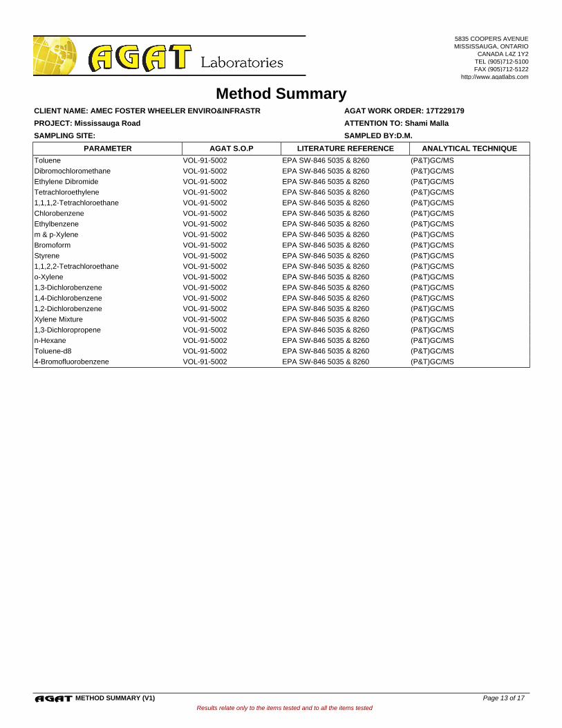
Toluene VOL-91-5002 EPA SW-846 5035 & 8260 (P&T)GC/MS
Dibromochloromethane VOL-91-5002 EPA SW-846 5035 & 8260 (P&T)GC/MS
Ethylene Dibromide VOL-91-5002 EPA SW-846 5035 & 8260 (P&T)GC/MS
Tetrachloroethylene VOL-91-5002 EPA SW-846 5035 & 8260 (P&T)GC/MS
1,1,1,2-Tetrachloroethane VOL-91-5002 EPA SW-846 5035 & 8260 (P&T)GC/MS
Chlorobenzene VOL-91-5002 EPA SW-846 5035 & 8260 (P&T)GC/MS
Ethylbenzene VOL-91-5002 EPA SW-846 5035 & 8260 (P&T)GC/MS
m & p-Xylene VOL-91-5002 EPA SW-846 5035 & 8260 (P&T)GC/MS
Bromoform VOL-91-5002 EPA SW-846 5035 & 8260 (P&T)GC/MS
Styrene VOL-91-5002 EPA SW-846 5035 & 8260 (P&T)GC/MS
1,1,2,2-Tetrachloroethane VOL-91-5002 EPA SW-846 5035 & 8260 (P&T)GC/MS
o-Xylene VOL-91-5002 EPA SW-846 5035 & 8260 (P&T)GC/MS
1,3-Dichlorobenzene VOL-91-5002 EPA SW-846 5035 & 8260 (P&T)GC/MS
1,4-Dichlorobenzene VOL-91-5002 EPA SW-846 5035 & 8260 (P&T)GC/MS
1,2-Dichlorobenzene VOL-91-5002 EPA SW-846 5035 & 8260 (P&T)GC/MS
Xylene Mixture VOL-91-5002 EPA SW-846 5035 & 8260 (P&T)GC/MS
1,3-Dichloropropene VOL-91-5002 EPA SW-846 5035 & 8260 (P&T)GC/MS
n-Hexane VOL-91-5002 EPA SW-846 5035 & 8260 (P&T)GC/MS
Toluene-d8 VOL-91-5002 EPA SW-846 5035 & 8260 (P&T)GC/MS
4-Bromofluorobenzene VOL-91-5002 EPA SW-846 5035 & 8260 (P&T)GC/MS
Results relate only to the items tested and to all the items tested
SAMPLING SITE: SAMPLED BY:D.M.
AGAT WORK ORDER: 17T229179
Method Summary
ATTENTION TO: Shami Malla
CLIENT NAME: AMEC FOSTER WHEELER ENVIRO&INFRASTR
PROJECT: Mississauga Road
AGAT S.O.P ANALYTICAL TECHNIQUELITERATURE REFERENCEPARAMETER
5835 COOPERS AVENUEMISSISSAUGA, ONTARIO
CANADA L4Z 1Y2TEL (905)712-5100FAX (905)712-5122
http://www.agatlabs.com
METHOD SUMMARY (V1) Page 13 of 17
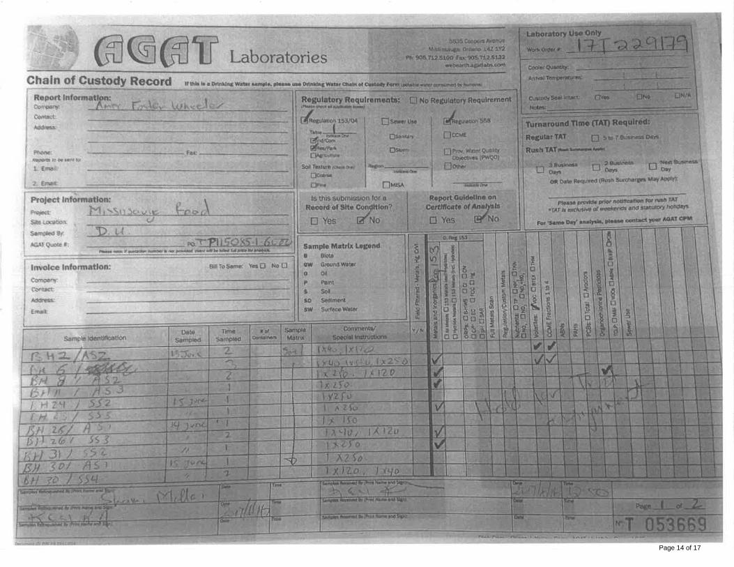
Page 14 of 17
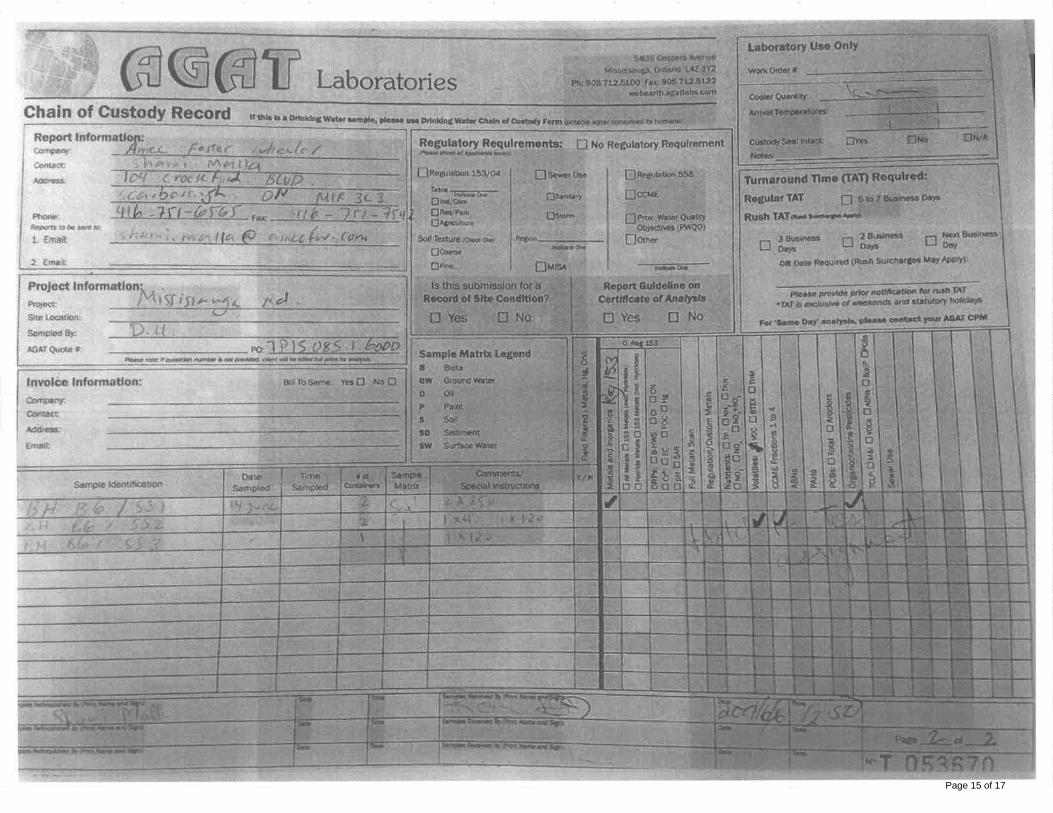
Page 15 of 17
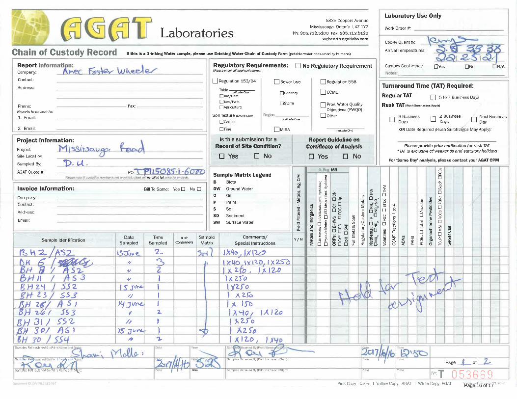
Page 16 of 17
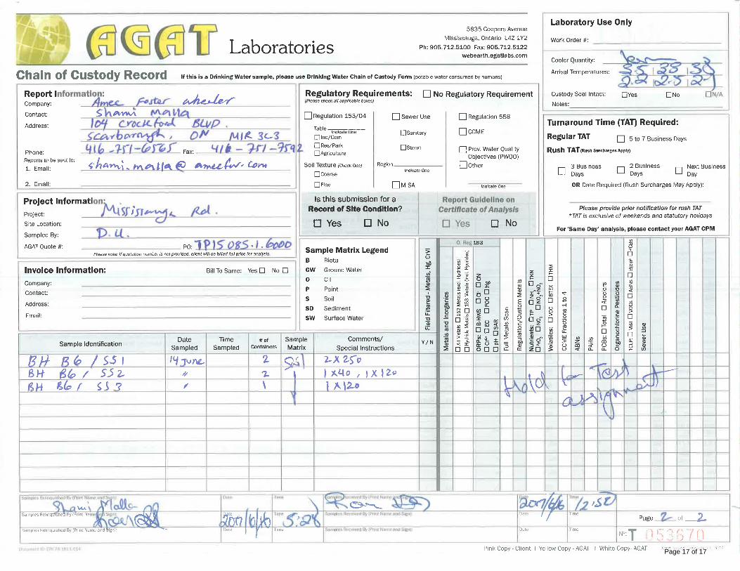
Page 17 of 17

CLIENT NAME: AMEC FOSTER WHEELER ENVIRO&INFRASTR104 CROCKFORD BLVDSCARBOROUGH, ON M1R3C3 (416) 751-6565
5835 COOPERS AVENUEMISSISSAUGA, ONTARIO
CANADA L4Z 1Y2TEL (905)712-5100FAX (905)712-5122
http://www.agatlabs.com
Amanjot Bhela, Inorganic CoordinatorSOIL ANALYSIS REVIEWED BY:
Neli Popnikolova, Senior ChemistTRACE ORGANICS REVIEWED BY:
DATE REPORTED:
PAGES (INCLUDING COVER): 16
Jul 19, 2017
VERSION*: 1
Should you require any information regarding this analysis please contact your client services representative at (905) 712-5100
17T230186AGAT WORK ORDER:
ATTENTION TO: Shami Malla
PROJECT: Mississauga Rd
Laboratories (V1) Page 1 of 16
All samples will be disposed of within 30 days following analysis. Please contact the lab if you require additional sample storage time.
AGAT Laboratories is accredited to ISO/IEC 17025 by the Canadian Association for Laboratory Accreditation Inc. (CALA) and/or Standards Council of Canada (SCC) for specific tests listed on the scope of accreditation. AGAT Laboratories (Mississauga) is also accredited by the Canadian Association for Laboratory Accreditation Inc. (CALA) for specific drinking water tests. Accreditations are location and parameter specific. A complete listing of parameters for each location is available from www.cala.ca and/or www.scc.ca. The tests in this report may not necessarily be included in the scope of accreditation.
Association of Professional Engineers and Geoscientists of Alberta (APEGA)Western Enviro-Agricultural Laboratory Association (WEALA)Environmental Services Association of Alberta (ESAA)
Member of:
*NOTES
Results relate only to the items tested and to all the items testedAll reportable information as specified by ISO 17025:2005 is available from AGAT Laboratories upon request
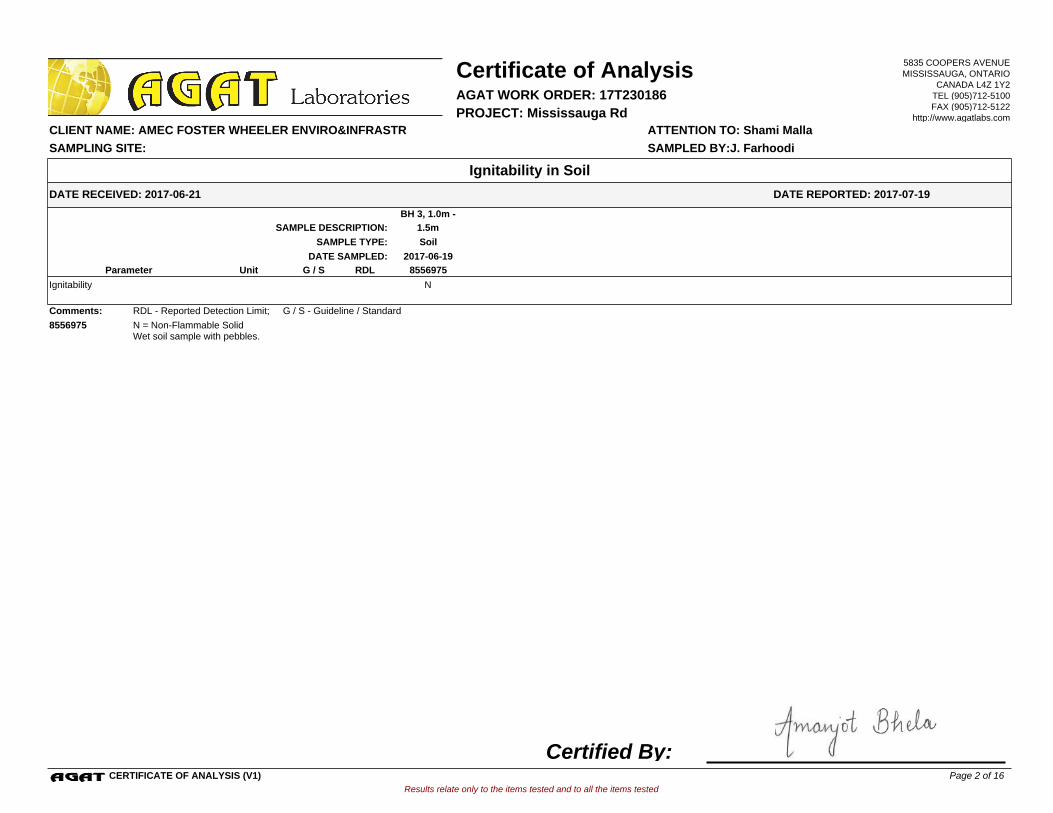
BH 3, 1.0m -
1.5mSAMPLE DESCRIPTION:
SoilSAMPLE TYPE:
2017-06-19DATE SAMPLED:
8556975G / S RDLUnitParameter
NIgnitability
Comments: RDL - Reported Detection Limit; G / S - Guideline / Standard
8556975 N = Non-Flammable SolidWet soil sample with pebbles.
Results relate only to the items tested and to all the items tested
DATE RECEIVED: 2017-06-21
Certificate of Analysis
ATTENTION TO: Shami Malla CLIENT NAME: AMEC FOSTER WHEELER ENVIRO&INFRASTR
AGAT WORK ORDER: 17T230186
DATE REPORTED: 2017-07-19
PROJECT: Mississauga Rd
Ignitability in Soil
SAMPLED BY:J. FarhoodiSAMPLING SITE:
5835 COOPERS AVENUEMISSISSAUGA, ONTARIO
CANADA L4Z 1Y2TEL (905)712-5100FAX (905)712-5122
http://www.agatlabs.com
CERTIFICATE OF ANALYSIS (V1)
Certified By:Page 2 of 16
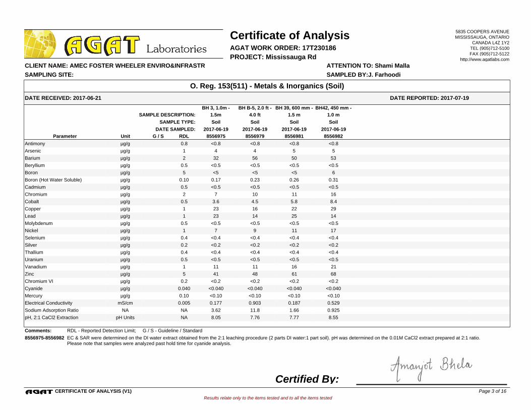
BH B-5, 2.0 ft -
4.0 ft
BH 3, 1.0m -
1.5m
BH 39, 600 mm -
1.5 m
BH42, 450 mm -
1.0 mSAMPLE DESCRIPTION:
SoilSoilSoil SoilSAMPLE TYPE:
2017-06-19 2017-06-19 2017-06-192017-06-19DATE SAMPLED:
8556975 8556979 8556981 8556982G / S RDLUnitParameter
<0.8 <0.8 <0.8 <0.8Antimony 0.8µg/g
4 4 5 5Arsenic 1µg/g
32 56 50 53Barium 2µg/g
<0.5 <0.5 <0.5 <0.5Beryllium 0.5µg/g
<5 <5 <5 6Boron 5µg/g
0.17 0.23 0.26 0.31Boron (Hot Water Soluble) 0.10µg/g
<0.5 <0.5 <0.5 <0.5Cadmium 0.5µg/g
7 10 11 16Chromium 2µg/g
3.6 4.5 5.8 8.4Cobalt 0.5µg/g
23 16 22 29Copper 1µg/g
23 14 25 14Lead 1µg/g
<0.5 <0.5 <0.5 <0.5Molybdenum 0.5µg/g
7 9 11 17Nickel 1µg/g
<0.4 <0.4 <0.4 <0.4Selenium 0.4µg/g
<0.2 <0.2 <0.2 <0.2Silver 0.2µg/g
<0.4 <0.4 <0.4 <0.4Thallium 0.4µg/g
<0.5 <0.5 <0.5 <0.5Uranium 0.5µg/g
11 11 16 21Vanadium 1µg/g
41 48 61 68Zinc 5µg/g
<0.2 <0.2 <0.2 <0.2Chromium VI 0.2µg/g
<0.040 <0.040 <0.040 <0.040Cyanide 0.040µg/g
<0.10 <0.10 <0.10 <0.10Mercury 0.10µg/g
0.177 0.903 0.187 0.529Electrical Conductivity 0.005mS/cm
3.62 11.8 1.66 0.925Sodium Adsorption Ratio NANA
8.05 7.76 7.77 8.55pH, 2:1 CaCl2 Extraction NApH Units
Comments: RDL - Reported Detection Limit; G / S - Guideline / Standard
8556975-8556982 EC & SAR were determined on the DI water extract obtained from the 2:1 leaching procedure (2 parts DI water:1 part soil). pH was determined on the 0.01M CaCl2 extract prepared at 2:1 ratio.Please note that samples were analyzed past hold time for cyanide analysis.
Results relate only to the items tested and to all the items tested
DATE RECEIVED: 2017-06-21
Certificate of Analysis
ATTENTION TO: Shami Malla CLIENT NAME: AMEC FOSTER WHEELER ENVIRO&INFRASTR
AGAT WORK ORDER: 17T230186
DATE REPORTED: 2017-07-19
PROJECT: Mississauga Rd
O. Reg. 153(511) - Metals & Inorganics (Soil)
SAMPLED BY:J. FarhoodiSAMPLING SITE:
5835 COOPERS AVENUEMISSISSAUGA, ONTARIO
CANADA L4Z 1Y2TEL (905)712-5100FAX (905)712-5122
http://www.agatlabs.com
CERTIFICATE OF ANALYSIS (V1)
Certified By:Page 3 of 16

BH 3, 1.0m -
1.5mSAMPLE DESCRIPTION:
SoilSAMPLE TYPE:
2017-06-19DATE SAMPLED:
8556975G / S RDLUnitParameter
<0.01Hexachloroethane 0.01µg/g
<0.005Gamma-Hexachlorocyclohexane 0.005µg/g
<0.005Heptachlor 0.005µg/g
<0.005Aldrin 0.005µg/g
<0.005Heptachlor Epoxide 0.005µg/g
<0.005Endosulfan 0.005µg/g
<0.007Chlordane 0.007µg/g
<0.007DDE 0.007µg/g
<0.007DDD 0.007µg/g
<0.007DDT 0.007µg/g
<0.005Dieldrin 0.005µg/g
<0.005Endrin 0.005µg/g
<0.005Methoxychlor 0.005µg/g
<0.005Hexachlorobenzene 0.005µg/g
<0.01Hexachlorobutadiene 0.01µg/g
11.1Moisture Content 0.1%
Acceptable LimitsUnitSurrogate
70TCMX % 50-140
80Decachlorobiphenyl % 60-130
Comments: RDL - Reported Detection Limit; G / S - Guideline / Standard
8556975 Results are based on the dry weight of the soil.Note: DDT applies to the total of op'DDT and pp'DDT, DDD applies to the total of op'DDD and pp'DDD and DDE applies to the total of op'DDE and pp'DDE. Endosulfan applies to the total of Endosulfan I and Endosulfan II.Chlordane applies to the total of Alpha-Chlordane and Gamma-Chlordane.
Results relate only to the items tested and to all the items tested
DATE RECEIVED: 2017-06-21
Certificate of Analysis
ATTENTION TO: Shami Malla CLIENT NAME: AMEC FOSTER WHEELER ENVIRO&INFRASTR
AGAT WORK ORDER: 17T230186
DATE REPORTED: 2017-07-19
PROJECT: Mississauga Rd
O. Reg. 153(511) - OC Pesticides (Soil)
SAMPLED BY:J. FarhoodiSAMPLING SITE:
5835 COOPERS AVENUEMISSISSAUGA, ONTARIO
CANADA L4Z 1Y2TEL (905)712-5100FAX (905)712-5122
http://www.agatlabs.com
CERTIFICATE OF ANALYSIS (V1)
Certified By:Page 4 of 16
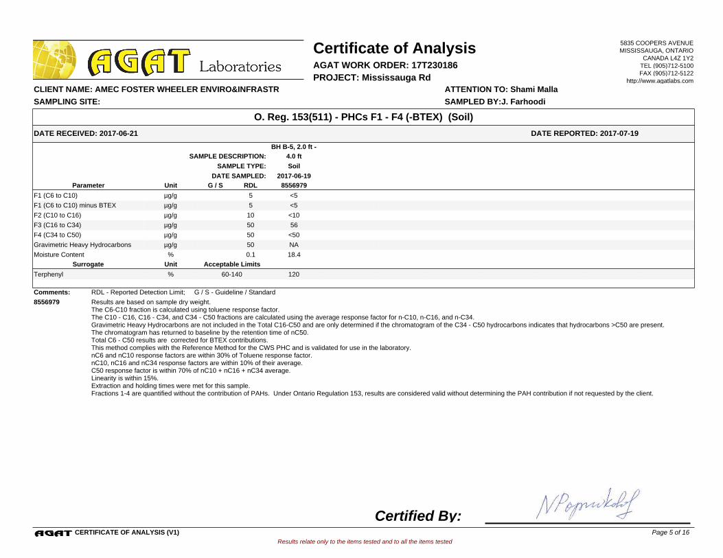
BH B-5, 2.0 ft -
4.0 ftSAMPLE DESCRIPTION:
SoilSAMPLE TYPE:
2017-06-19DATE SAMPLED:
8556979G / S RDLUnitParameter
<5F1 (C6 to C10) 5µg/g
<5F1 (C6 to C10) minus BTEX 5µg/g
<10F2 (C10 to C16) 10µg/g
56F3 (C16 to C34) 50µg/g
<50F4 (C34 to C50) 50µg/g
NAGravimetric Heavy Hydrocarbons 50µg/g
18.4Moisture Content 0.1%
Acceptable LimitsUnitSurrogate
120Terphenyl % 60-140
Comments: RDL - Reported Detection Limit; G / S - Guideline / Standard
8556979 Results are based on sample dry weight.The C6-C10 fraction is calculated using toluene response factor.The C10 - C16, C16 - C34, and C34 - C50 fractions are calculated using the average response factor for n-C10, n-C16, and n-C34.Gravimetric Heavy Hydrocarbons are not included in the Total C16-C50 and are only determined if the chromatogram of the C34 - C50 hydrocarbons indicates that hydrocarbons >C50 are present.The chromatogram has returned to baseline by the retention time of nC50.Total C6 - C50 results are corrected for BTEX contributions.This method complies with the Reference Method for the CWS PHC and is validated for use in the laboratory.nC6 and nC10 response factors are within 30% of Toluene response factor.nC10, nC16 and nC34 response factors are within 10% of their average.C50 response factor is within 70% of nC10 + nC16 + nC34 average.Linearity is within 15%.Extraction and holding times were met for this sample.Fractions 1-4 are quantified without the contribution of PAHs. Under Ontario Regulation 153, results are considered valid without determining the PAH contribution if not requested by the client.
Results relate only to the items tested and to all the items tested
DATE RECEIVED: 2017-06-21
Certificate of Analysis
ATTENTION TO: Shami Malla CLIENT NAME: AMEC FOSTER WHEELER ENVIRO&INFRASTR
AGAT WORK ORDER: 17T230186
DATE REPORTED: 2017-07-19
PROJECT: Mississauga Rd
O. Reg. 153(511) - PHCs F1 - F4 (-BTEX) (Soil)
SAMPLED BY:J. FarhoodiSAMPLING SITE:
5835 COOPERS AVENUEMISSISSAUGA, ONTARIO
CANADA L4Z 1Y2TEL (905)712-5100FAX (905)712-5122
http://www.agatlabs.com
CERTIFICATE OF ANALYSIS (V1)
Certified By:Page 5 of 16
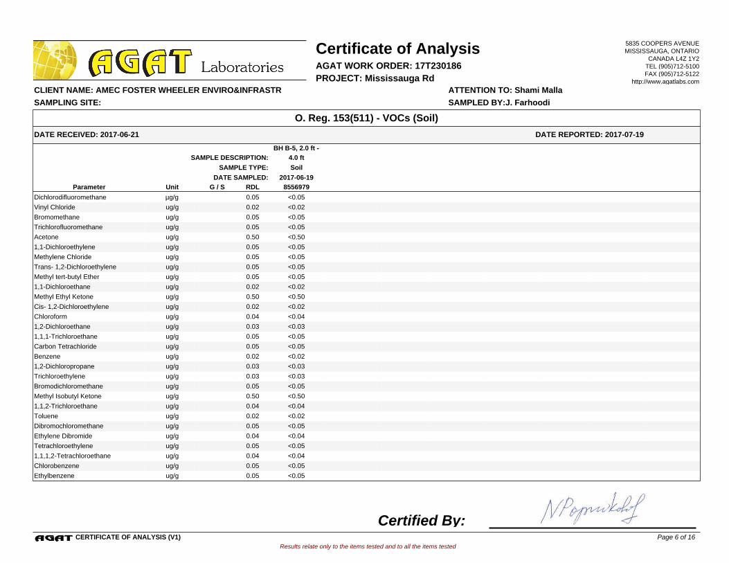
BH B-5, 2.0 ft -
4.0 ftSAMPLE DESCRIPTION:
SoilSAMPLE TYPE:
2017-06-19DATE SAMPLED:
8556979G / S RDLUnitParameter
<0.05Dichlorodifluoromethane 0.05µg/g
<0.02Vinyl Chloride 0.02ug/g
<0.05Bromomethane 0.05ug/g
<0.05Trichlorofluoromethane 0.05ug/g
<0.50Acetone 0.50ug/g
<0.051,1-Dichloroethylene 0.05ug/g
<0.05Methylene Chloride 0.05ug/g
<0.05Trans- 1,2-Dichloroethylene 0.05ug/g
<0.05Methyl tert-butyl Ether 0.05ug/g
<0.021,1-Dichloroethane 0.02ug/g
<0.50Methyl Ethyl Ketone 0.50ug/g
<0.02Cis- 1,2-Dichloroethylene 0.02ug/g
<0.04Chloroform 0.04ug/g
<0.031,2-Dichloroethane 0.03ug/g
<0.051,1,1-Trichloroethane 0.05ug/g
<0.05Carbon Tetrachloride 0.05ug/g
<0.02Benzene 0.02ug/g
<0.031,2-Dichloropropane 0.03ug/g
<0.03Trichloroethylene 0.03ug/g
<0.05Bromodichloromethane 0.05ug/g
<0.50Methyl Isobutyl Ketone 0.50ug/g
<0.041,1,2-Trichloroethane 0.04ug/g
<0.02Toluene 0.02ug/g
<0.05Dibromochloromethane 0.05ug/g
<0.04Ethylene Dibromide 0.04ug/g
<0.05Tetrachloroethylene 0.05ug/g
<0.041,1,1,2-Tetrachloroethane 0.04ug/g
<0.05Chlorobenzene 0.05ug/g
<0.05Ethylbenzene 0.05ug/g
Results relate only to the items tested and to all the items tested
DATE RECEIVED: 2017-06-21
Certificate of Analysis
ATTENTION TO: Shami Malla CLIENT NAME: AMEC FOSTER WHEELER ENVIRO&INFRASTR
AGAT WORK ORDER: 17T230186
DATE REPORTED: 2017-07-19
PROJECT: Mississauga Rd
O. Reg. 153(511) - VOCs (Soil)
SAMPLED BY:J. FarhoodiSAMPLING SITE:
5835 COOPERS AVENUEMISSISSAUGA, ONTARIO
CANADA L4Z 1Y2TEL (905)712-5100FAX (905)712-5122
http://www.agatlabs.com
CERTIFICATE OF ANALYSIS (V1)
Certified By:Page 6 of 16
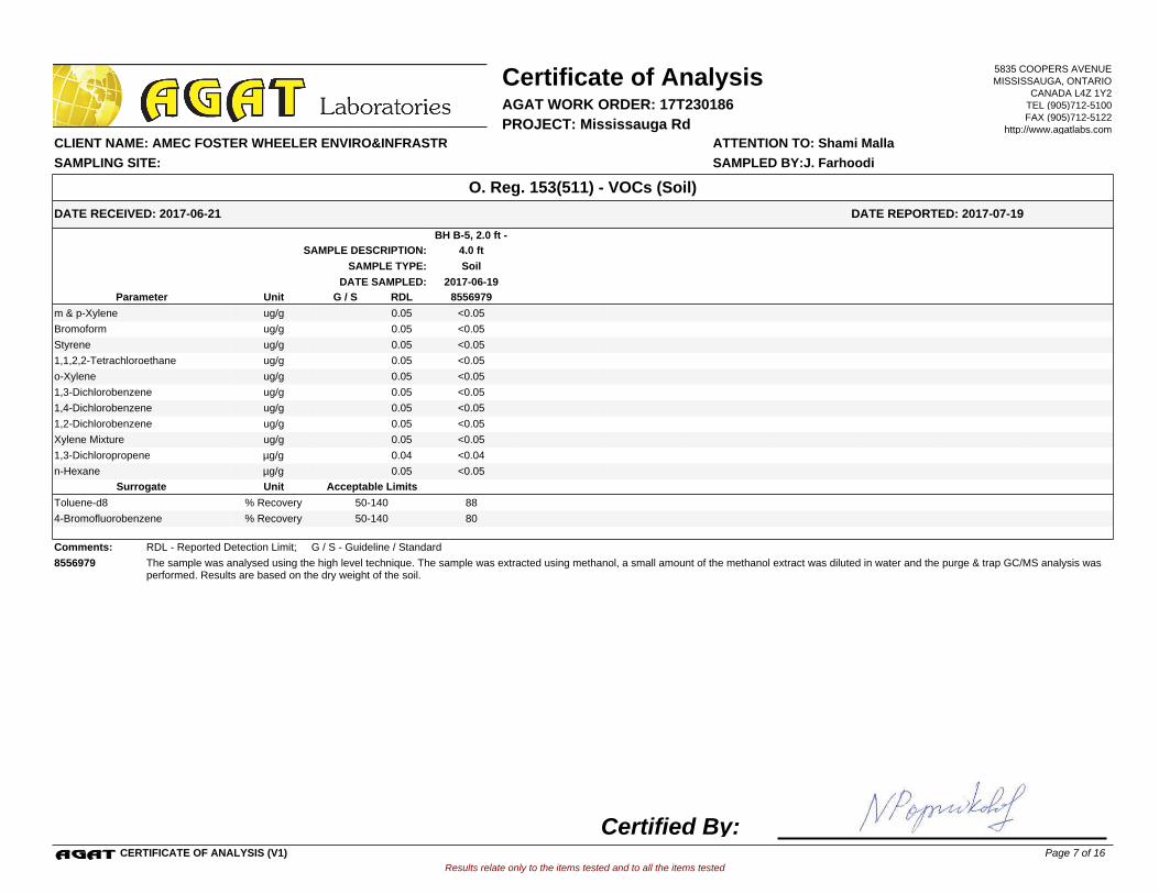
BH B-5, 2.0 ft -
4.0 ftSAMPLE DESCRIPTION:
SoilSAMPLE TYPE:
2017-06-19DATE SAMPLED:
8556979G / S RDLUnitParameter
<0.05m & p-Xylene 0.05ug/g
<0.05Bromoform 0.05ug/g
<0.05Styrene 0.05ug/g
<0.051,1,2,2-Tetrachloroethane 0.05ug/g
<0.05o-Xylene 0.05ug/g
<0.051,3-Dichlorobenzene 0.05ug/g
<0.051,4-Dichlorobenzene 0.05ug/g
<0.051,2-Dichlorobenzene 0.05ug/g
<0.05Xylene Mixture 0.05ug/g
<0.041,3-Dichloropropene 0.04µg/g
<0.05n-Hexane 0.05µg/g
Acceptable LimitsUnitSurrogate
88Toluene-d8 % Recovery 50-140
804-Bromofluorobenzene % Recovery 50-140
Comments: RDL - Reported Detection Limit; G / S - Guideline / Standard
8556979 The sample was analysed using the high level technique. The sample was extracted using methanol, a small amount of the methanol extract was diluted in water and the purge & trap GC/MS analysis was performed. Results are based on the dry weight of the soil.
Results relate only to the items tested and to all the items tested
DATE RECEIVED: 2017-06-21
Certificate of Analysis
ATTENTION TO: Shami Malla CLIENT NAME: AMEC FOSTER WHEELER ENVIRO&INFRASTR
AGAT WORK ORDER: 17T230186
DATE REPORTED: 2017-07-19
PROJECT: Mississauga Rd
O. Reg. 153(511) - VOCs (Soil)
SAMPLED BY:J. FarhoodiSAMPLING SITE:
5835 COOPERS AVENUEMISSISSAUGA, ONTARIO
CANADA L4Z 1Y2TEL (905)712-5100FAX (905)712-5122
http://www.agatlabs.com
CERTIFICATE OF ANALYSIS (V1)
Certified By:Page 7 of 16

O. Reg. 153(511) - Metals & Inorganics (Soil)
Antimony 8556975 8556975 <0.8 <0.8 NA < 0.8 85% 70% 130% 102% 80% 120% 102% 70% 130%
Arsenic 8556975 8556975 4 4 NA < 1 92% 70% 130% 99% 80% 120% 103% 70% 130%
Barium 8556975 8556975 32 32 0.0% < 2 102% 70% 130% 104% 80% 120% 100% 70% 130%
Beryllium 8556975 8556975 <0.5 <0.5 NA < 0.5 81% 70% 130% 103% 80% 120% 94% 70% 130%
Boron
8556975 8556975 <5 <5 NA < 5 86% 70% 130% 106% 80% 120% 100% 70% 130%
Boron (Hot Water Soluble) 8556975 8556975 0.17 0.15 NA < 0.10 84% 60% 140% 94% 70% 130% 97% 60% 140%
Cadmium 8556975 8556975 <0.5 <0.5 NA < 0.5 102% 70% 130% 102% 80% 120% 105% 70% 130%
Chromium 8556975 8556975 7 8 NA < 2 75% 70% 130% 105% 80% 120% 104% 70% 130%
Cobalt 8556975 8556975 3.6 3.7 2.7% < 0.5 92% 70% 130% 106% 80% 120% 103% 70% 130%
Copper
8556975 8556975 23 24 4.3% < 1 91% 70% 130% 110% 80% 120% 105% 70% 130%
Lead 8556975 8556975 23 24 4.3% < 1 101% 70% 130% 105% 80% 120% 103% 70% 130%
Molybdenum 8556975 8556975 <0.5 <0.5 NA < 0.5 88% 70% 130% 108% 80% 120% 107% 70% 130%
Nickel 8556975 8556975 7 7 0.0% < 1 96% 70% 130% 112% 80% 120% 107% 70% 130%
Selenium 8556975 8556975 <0.4 <0.4 NA < 0.4 82% 70% 130% 104% 80% 120% 109% 70% 130%
Silver
8556975 8556975 <0.2 <0.2 NA < 0.2 82% 70% 130% 106% 80% 120% 110% 70% 130%
Thallium 8556975 8556975 <0.4 <0.4 NA < 0.4 79% 70% 130% 104% 80% 120% 102% 70% 130%
Uranium 8556975 8556975 <0.5 <0.5 NA < 0.5 88% 70% 130% 105% 80% 120% 100% 70% 130%
Vanadium 8556975 8556975 11 10 9.5% < 1 89% 70% 130% 103% 80% 120% 105% 70% 130%
Zinc 8556975 8556975 41 41 0.0% < 5 99% 70% 130% 112% 80% 120% 114% 70% 130%
Chromium VI
8558036 <0.2 <0.2 NA < 0.2 93% 70% 130% 101% 80% 120% 98% 70% 130%
Cyanide 8552648 <0.040 <0.040 NA < 0.040 92% 70% 130% 100% 80% 120% 102% 70% 130%
Mercury 8556975 8556975 <0.10 <0.10 NA < 0.10 96% 70% 130% 95% 80% 120% 98% 70% 130%
Electrical Conductivity 8556975 8556975 0.177 0.184 3.9% < 0.005 96% 90% 110% NA NA
Sodium Adsorption Ratio 8556975 8556975 3.62 3.70 2.2% NA NA NA NA
pH, 2:1 CaCl2 Extraction
8556981 8556981 7.77 7.79 0.3% NA 101% 80% 120% NA NA
O. Reg. 558 Metals and Inorganics
Arsenic Leachate 8553822 <0.010 <0.010 NA < 0.010 99% 90% 110% 92% 80% 120% 103% 70% 130%
Barium Leachate 8553822 0.495 0.467 NA < 0.100 103% 90% 110% 102% 80% 120% 98% 70% 130%
Boron Leachate 8553822 0.057 0.058 NA < 0.050 98% 90% 110% 99% 80% 120% 88% 70% 130%
Cadmium Leachate 8553822 <0.010 <0.010 NA < 0.010 102% 90% 110% 97% 80% 120% 115% 70% 130%
Chromium Leachate
8553822 <0.010 <0.010 NA < 0.010 103% 90% 110% 102% 80% 120% 107% 70% 130%
Lead Leachate 8553822 0.012 0.012 NA < 0.010 103% 90% 110% 98% 80% 120% 95% 70% 130%
Mercury Leachate 8553822 <0.01 <0.01 NA < 0.01 100% 90% 110% 94% 80% 120% 92% 70% 130%
Selenium Leachate 8553822 <0.010 <0.010 NA < 0.010 102% 90% 110% 100% 80% 120% 104% 70% 130%
Silver Leachate 8553822 <0.010 <0.010 NA < 0.010 103% 90% 110% 96% 80% 120% 103% 70% 130%
Uranium Leachate
8553822 <0.050 <0.050 NA < 0.050 101% 90% 110% 100% 80% 120% 98% 70% 130%
Fluoride Leachate 8553822 <0.05 <0.05 NA < 0.05 101% 90% 110% 107% 90% 110% 101% 70% 130%
Cyanide Leachate 8553822 <0.05 <0.05 NA < 0.05 92% 90% 110% 100% 90% 110% 100% 70% 130%
(Nitrate + Nitrite) as N Leachate 8553822 <0.70 <0.70 NA < 0.70 101% 80% 120% 98% 80% 120% 96% 70% 130%
Results relate only to the items tested and to all the items tested
SAMPLING SITE: SAMPLED BY:J. Farhoodi
AGAT WORK ORDER: 17T230186
Dup #1 RPDMeasured
ValueRecovery Recovery
Quality Assurance
ATTENTION TO: Shami Malla
CLIENT NAME: AMEC FOSTER WHEELER ENVIRO&INFRASTR
PROJECT: Mississauga Rd
Soil Analysis
UpperLower
AcceptableLimits
BatchPARAMETERSample
IdDup #2
UpperLower
AcceptableLimits
UpperLower
AcceptableLimits
MATRIX SPIKEMETHOD BLANK SPIKEDUPLICATERPT Date: Jul 19, 2017 REFERENCE MATERIAL
MethodBlank
5835 COOPERS AVENUEMISSISSAUGA, ONTARIO
CANADA L4Z 1Y2TEL (905)712-5100FAX (905)712-5122
http://www.agatlabs.com
QUALITY ASSURANCE REPORT (V1) Page 8 of 16
AGAT Laboratories is accredited to ISO/IEC 17025 by the Canadian Association for Laboratory Accreditation Inc. (CALA) and/or Standards Council of Canada (SCC) for specific tests listed on the scope of accreditation. AGAT Laboratories (Mississauga) is also accredited by the Canadian Association for Laboratory Accreditation Inc. (CALA) for specific drinking water tests. Accreditations are location and parameter specific. A complete listing of parameters for each location is available from www.cala.ca and/or www.scc.ca. The tests in this report may not necessarily be included in the scope of accreditation.

Comments: NA signifies Not Applicable.Duplicate Qualifier: As the measured result approaches the RL, the uncertainty associated with the value increases dramatically, thus duplicate acceptance limits apply only where the average of the two duplicates is greater than five times the RL.
Certified By:
Results relate only to the items tested and to all the items tested
SAMPLING SITE: SAMPLED BY:J. Farhoodi
AGAT WORK ORDER: 17T230186
Dup #1 RPDMeasured
ValueRecovery Recovery
Quality Assurance
ATTENTION TO: Shami Malla
CLIENT NAME: AMEC FOSTER WHEELER ENVIRO&INFRASTR
PROJECT: Mississauga Rd
Soil Analysis (Continued)
UpperLower
AcceptableLimits
BatchPARAMETERSample
IdDup #2
UpperLower
AcceptableLimits
UpperLower
AcceptableLimits
MATRIX SPIKEMETHOD BLANK SPIKEDUPLICATERPT Date: Jul 19, 2017 REFERENCE MATERIAL
MethodBlank
5835 COOPERS AVENUEMISSISSAUGA, ONTARIO
CANADA L4Z 1Y2TEL (905)712-5100FAX (905)712-5122
http://www.agatlabs.com
QUALITY ASSURANCE REPORT (V1) Page 9 of 16
AGAT Laboratories is accredited to ISO/IEC 17025 by the Canadian Association for Laboratory Accreditation Inc. (CALA) and/or Standards Council of Canada (SCC) for specific tests listed on the scope of accreditation. AGAT Laboratories (Mississauga) is also accredited by the Canadian Association for Laboratory Accreditation Inc. (CALA) for specific drinking water tests. Accreditations are location and parameter specific. A complete listing of parameters for each location is available from www.cala.ca and/or www.scc.ca. The tests in this report may not necessarily be included in the scope of accreditation.

O. Reg. 153(511) - VOCs (Soil)
Dichlorodifluoromethane 8551744 < 0.05 < 0.05 NA < 0.05 89% 50% 140% 94% 50% 140% 87% 50% 140%
Vinyl Chloride 8551744 < 0.02 < 0.02 NA < 0.02 93% 50% 140% 92% 50% 140% 89% 50% 140%
Bromomethane 8551744 < 0.05 < 0.05 NA < 0.05 97% 50% 140% 90% 50% 140% 96% 50% 140%
Trichlorofluoromethane 8551744 < 0.05 < 0.05 NA < 0.05 93% 50% 140% 86% 50% 140% 89% 50% 140%
Acetone
8551744 < 0.50 < 0.50 NA < 0.50 99% 50% 140% 95% 50% 140% 90% 50% 140%
1,1-Dichloroethylene 8551744 < 0.05 < 0.05 NA < 0.05 99% 50% 140% 95% 60% 130% 99% 50% 140%
Methylene Chloride 8551744 < 0.05 < 0.05 NA < 0.05 94% 50% 140% 95% 60% 130% 97% 50% 140%
Trans- 1,2-Dichloroethylene 8551744 < 0.05 < 0.05 NA < 0.05 99% 50% 140% 97% 60% 130% 91% 50% 140%
Methyl tert-butyl Ether 8551744 < 0.05 < 0.05 NA < 0.05 98% 50% 140% 94% 60% 130% 97% 50% 140%
1,1-Dichloroethane
8551744 < 0.02 < 0.02 NA < 0.02 87% 50% 140% 97% 60% 130% 92% 50% 140%
Methyl Ethyl Ketone 8551744 < 0.50 < 0.50 NA < 0.50 99% 50% 140% 96% 50% 140% 91% 50% 140%
Cis- 1,2-Dichloroethylene 8551744 < 0.02 < 0.02 NA < 0.02 91% 50% 140% 96% 60% 130% 97% 50% 140%
Chloroform 8551744 < 0.04 < 0.04 NA < 0.04 97% 50% 140% 94% 60% 130% 94% 50% 140%
1,2-Dichloroethane 8551744 < 0.03 < 0.03 NA < 0.03 96% 50% 140% 93% 60% 130% 92% 50% 140%
1,1,1-Trichloroethane
8551744 < 0.05 < 0.05 NA < 0.05 95% 50% 140% 96% 60% 130% 99% 50% 140%
Carbon Tetrachloride 8551744 < 0.05 < 0.05 NA < 0.05 96% 50% 140% 99% 60% 130% 98% 50% 140%
Benzene 8551744 < 0.02 < 0.02 NA < 0.02 96% 50% 140% 87% 60% 130% 92% 50% 140%
1,2-Dichloropropane 8551744 < 0.03 < 0.03 NA < 0.03 97% 50% 140% 95% 60% 130% 91% 50% 140%
Trichloroethylene 8551744 < 0.03 < 0.03 NA < 0.03 88% 50% 140% 90% 60% 130% 91% 50% 140%
Bromodichloromethane
8551744 < 0.05 < 0.05 NA < 0.05 94% 50% 140% 94% 60% 130% 93% 50% 140%
Methyl Isobutyl Ketone 8551744 < 0.50 < 0.50 NA < 0.50 83% 50% 140% 95% 50% 140% 90% 50% 140%
1,1,2-Trichloroethane 8551744 < 0.04 < 0.04 NA < 0.04 88% 50% 140% 97% 60% 130% 96% 50% 140%
Toluene 8551744 < 0.02 < 0.02 NA < 0.02 91% 50% 140% 97% 60% 130% 97% 50% 140%
Dibromochloromethane 8551744 < 0.05 < 0.05 NA < 0.05 98% 50% 140% 98% 60% 130% 94% 50% 140%
Ethylene Dibromide
8551744 < 0.04 < 0.04 NA < 0.04 93% 50% 140% 97% 60% 130% 98% 50% 140%
Tetrachloroethylene 8551744 < 0.05 < 0.05 NA < 0.05 97% 50% 140% 98% 60% 130% 100% 50% 140%
1,1,1,2-Tetrachloroethane 8551744 < 0.04 < 0.04 NA < 0.04 97% 50% 140% 93% 60% 130% 90% 50% 140%
Chlorobenzene 8551744 < 0.05 < 0.05 NA < 0.05 95% 50% 140% 97% 60% 130% 87% 50% 140%
Ethylbenzene 8551744 < 0.05 < 0.05 NA < 0.05 98% 50% 140% 81% 60% 130% 83% 50% 140%
m & p-Xylene
8551744 < 0.05 < 0.05 NA < 0.05 75% 50% 140% 72% 60% 130% 73% 50% 140%
Bromoform 8551744 < 0.05 < 0.05 NA < 0.05 96% 50% 140% 94% 60% 130% 91% 50% 140%
Styrene 8551744 < 0.05 < 0.05 NA < 0.05 85% 50% 140% 92% 60% 130% 89% 50% 140%
1,1,2,2-Tetrachloroethane 8551744 < 0.05 < 0.05 NA < 0.05 93% 50% 140% 96% 60% 130% 100% 50% 140%
o-Xylene 8551744 < 0.05 < 0.05 NA < 0.05 96% 50% 140% 92% 60% 130% 87% 50% 140%
1,3-Dichlorobenzene
8551744 < 0.05 < 0.05 NA < 0.05 94% 50% 140% 88% 60% 130% 99% 50% 140%
1,4-Dichlorobenzene 8551744 < 0.05 < 0.05 NA < 0.05 93% 50% 140% 87% 60% 130% 95% 50% 140%
1,2-Dichlorobenzene 8551744 < 0.05 < 0.05 NA < 0.05 91% 50% 140% 82% 60% 130% 98% 50% 140%
1,3-Dichloropropene 8551744 < 0.04 < 0.04 NA < 0.04 95% 50% 140% 90% 60% 130% 84% 50% 140%
n-Hexane 8551744 < 0.05 < 0.05 NA < 0.05 98% 50% 140% 90% 60% 130% 90% 50% 140%
Results relate only to the items tested and to all the items tested
SAMPLING SITE: SAMPLED BY:J. Farhoodi
AGAT WORK ORDER: 17T230186
Dup #1 RPDMeasured
ValueRecovery Recovery
Quality Assurance
ATTENTION TO: Shami Malla
CLIENT NAME: AMEC FOSTER WHEELER ENVIRO&INFRASTR
PROJECT: Mississauga Rd
Trace Organics Analysis
UpperLower
AcceptableLimits
BatchPARAMETERSample
IdDup #2
UpperLower
AcceptableLimits
UpperLower
AcceptableLimits
MATRIX SPIKEMETHOD BLANK SPIKEDUPLICATERPT Date: Jul 19, 2017 REFERENCE MATERIAL
MethodBlank
5835 COOPERS AVENUEMISSISSAUGA, ONTARIO
CANADA L4Z 1Y2TEL (905)712-5100FAX (905)712-5122
http://www.agatlabs.com
QUALITY ASSURANCE REPORT (V1) Page 10 of 16
AGAT Laboratories is accredited to ISO/IEC 17025 by the Canadian Association for Laboratory Accreditation Inc. (CALA) and/or Standards Council of Canada (SCC) for specific tests listed on the scope of accreditation. AGAT Laboratories (Mississauga) is also accredited by the Canadian Association for Laboratory Accreditation Inc. (CALA) for specific drinking water tests. Accreditations are location and parameter specific. A complete listing of parameters for each location is available from www.cala.ca and/or www.scc.ca. The tests in this report may not necessarily be included in the scope of accreditation.
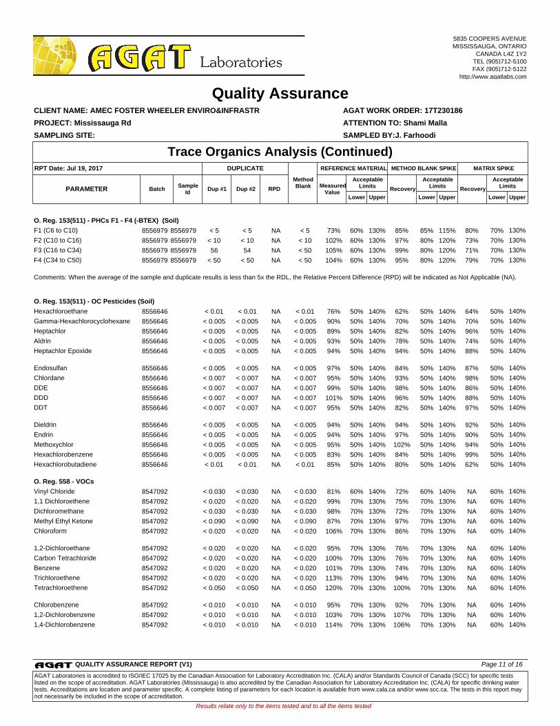
O. Reg. 153(511) - PHCs F1 - F4 (-BTEX) (Soil)
F1 (C6 to C10) 8556979 8556979 < 5 < 5 NA < 5 73% 60% 130% 85% 85% 115% 80% 70% 130%
F2 (C10 to C16) 8556979 8556979 < 10 < 10 NA < 10 102% 60% 130% 97% 80% 120% 73% 70% 130%
F3 (C16 to C34) 8556979 8556979 56 54 NA < 50 105% 60% 130% 99% 80% 120% 71% 70% 130%
F4 (C34 to C50) 8556979 8556979 < 50 < 50 NA < 50 104% 60% 130% 95% 80% 120% 79% 70% 130%
Comments: When the average of the sample and duplicate results is less than 5x the RDL, the Relative Percent Difference (RPD) will be indicated as Not Applicable (NA).
O. Reg. 153(511) - OC Pesticides (Soil)
Hexachloroethane 8556646 < 0.01 < 0.01 NA < 0.01 76% 50% 140% 62% 50% 140% 64% 50% 140%
Gamma-Hexachlorocyclohexane 8556646 < 0.005 < 0.005 NA < 0.005 90% 50% 140% 70% 50% 140% 70% 50% 140%
Heptachlor 8556646 < 0.005 < 0.005 NA < 0.005 89% 50% 140% 82% 50% 140% 96% 50% 140%
Aldrin 8556646 < 0.005 < 0.005 NA < 0.005 93% 50% 140% 78% 50% 140% 74% 50% 140%
Heptachlor Epoxide
8556646 < 0.005 < 0.005 NA < 0.005 94% 50% 140% 94% 50% 140% 88% 50% 140%
Endosulfan 8556646 < 0.005 < 0.005 NA < 0.005 97% 50% 140% 84% 50% 140% 87% 50% 140%
Chlordane 8556646 < 0.007 < 0.007 NA < 0.007 95% 50% 140% 93% 50% 140% 98% 50% 140%
DDE 8556646 < 0.007 < 0.007 NA < 0.007 99% 50% 140% 98% 50% 140% 86% 50% 140%
DDD 8556646 < 0.007 < 0.007 NA < 0.007 101% 50% 140% 96% 50% 140% 88% 50% 140%
DDT
8556646 < 0.007 < 0.007 NA < 0.007 95% 50% 140% 82% 50% 140% 97% 50% 140%
Dieldrin 8556646 < 0.005 < 0.005 NA < 0.005 94% 50% 140% 94% 50% 140% 92% 50% 140%
Endrin 8556646 < 0.005 < 0.005 NA < 0.005 94% 50% 140% 97% 50% 140% 90% 50% 140%
Methoxychlor 8556646 < 0.005 < 0.005 NA < 0.005 95% 50% 140% 102% 50% 140% 94% 50% 140%
Hexachlorobenzene 8556646 < 0.005 < 0.005 NA < 0.005 83% 50% 140% 84% 50% 140% 99% 50% 140%
Hexachlorobutadiene
8556646 < 0.01 < 0.01 NA < 0.01 85% 50% 140% 80% 50% 140% 62% 50% 140%
O. Reg. 558 - VOCs
Vinyl Chloride 8547092 < 0.030 < 0.030 NA < 0.030 81% 60% 140% 72% 60% 140% NA 60% 140%
1,1 Dichloroethene 8547092 < 0.020 < 0.020 NA < 0.020 99% 70% 130% 75% 70% 130% NA 60% 140%
Dichloromethane 8547092 < 0.030 < 0.030 NA < 0.030 98% 70% 130% 72% 70% 130% NA 60% 140%
Methyl Ethyl Ketone 8547092 < 0.090 < 0.090 NA < 0.090 87% 70% 130% 97% 70% 130% NA 60% 140%
Chloroform
8547092 < 0.020 < 0.020 NA < 0.020 106% 70% 130% 86% 70% 130% NA 60% 140%
1,2-Dichloroethane 8547092 < 0.020 < 0.020 NA < 0.020 95% 70% 130% 76% 70% 130% NA 60% 140%
Carbon Tetrachloride 8547092 < 0.020 < 0.020 NA < 0.020 100% 70% 130% 76% 70% 130% NA 60% 140%
Benzene 8547092 < 0.020 < 0.020 NA < 0.020 101% 70% 130% 74% 70% 130% NA 60% 140%
Trichloroethene 8547092 < 0.020 < 0.020 NA < 0.020 113% 70% 130% 94% 70% 130% NA 60% 140%
Tetrachloroethene
8547092 < 0.050 < 0.050 NA < 0.050 120% 70% 130% 100% 70% 130% NA 60% 140%
Chlorobenzene 8547092 < 0.010 < 0.010 NA < 0.010 95% 70% 130% 92% 70% 130% NA 60% 140%
1,2-Dichlorobenzene 8547092 < 0.010 < 0.010 NA < 0.010 103% 70% 130% 107% 70% 130% NA 60% 140%
1,4-Dichlorobenzene 8547092 < 0.010 < 0.010 NA < 0.010 114% 70% 130% 106% 70% 130% NA 60% 140%
Results relate only to the items tested and to all the items tested
SAMPLING SITE: SAMPLED BY:J. Farhoodi
AGAT WORK ORDER: 17T230186
Dup #1 RPDMeasured
ValueRecovery Recovery
Quality Assurance
ATTENTION TO: Shami Malla
CLIENT NAME: AMEC FOSTER WHEELER ENVIRO&INFRASTR
PROJECT: Mississauga Rd
Trace Organics Analysis (Continued)
UpperLower
AcceptableLimits
BatchPARAMETERSample
IdDup #2
UpperLower
AcceptableLimits
UpperLower
AcceptableLimits
MATRIX SPIKEMETHOD BLANK SPIKEDUPLICATERPT Date: Jul 19, 2017 REFERENCE MATERIAL
MethodBlank
5835 COOPERS AVENUEMISSISSAUGA, ONTARIO
CANADA L4Z 1Y2TEL (905)712-5100FAX (905)712-5122
http://www.agatlabs.com
QUALITY ASSURANCE REPORT (V1) Page 11 of 16
AGAT Laboratories is accredited to ISO/IEC 17025 by the Canadian Association for Laboratory Accreditation Inc. (CALA) and/or Standards Council of Canada (SCC) for specific tests listed on the scope of accreditation. AGAT Laboratories (Mississauga) is also accredited by the Canadian Association for Laboratory Accreditation Inc. (CALA) for specific drinking water tests. Accreditations are location and parameter specific. A complete listing of parameters for each location is available from www.cala.ca and/or www.scc.ca. The tests in this report may not necessarily be included in the scope of accreditation.

Results relate only to the items tested and to all the items tested
SAMPLING SITE: SAMPLED BY:J. Farhoodi
AGAT WORK ORDER: 17T230186
Dup #1 RPDMeasured
ValueRecovery Recovery
Quality Assurance
ATTENTION TO: Shami Malla
CLIENT NAME: AMEC FOSTER WHEELER ENVIRO&INFRASTR
PROJECT: Mississauga Rd
Trace Organics Analysis (Continued)
UpperLower
AcceptableLimits
BatchPARAMETERSample
IdDup #2
UpperLower
AcceptableLimits
UpperLower
AcceptableLimits
MATRIX SPIKEMETHOD BLANK SPIKEDUPLICATERPT Date: Jul 19, 2017 REFERENCE MATERIAL
MethodBlank
5835 COOPERS AVENUEMISSISSAUGA, ONTARIO
CANADA L4Z 1Y2TEL (905)712-5100FAX (905)712-5122
http://www.agatlabs.com
Certified By:QUALITY ASSURANCE REPORT (V1) Page 12 of 16
AGAT Laboratories is accredited to ISO/IEC 17025 by the Canadian Association for Laboratory Accreditation Inc. (CALA) and/or Standards Council of Canada (SCC) for specific tests listed on the scope of accreditation. AGAT Laboratories (Mississauga) is also accredited by the Canadian Association for Laboratory Accreditation Inc. (CALA) for specific drinking water tests. Accreditations are location and parameter specific. A complete listing of parameters for each location is available from www.cala.ca and/or www.scc.ca. The tests in this report may not necessarily be included in the scope of accreditation.

Soil Analysis
Ignitability EPA SW-846 1030 BURN MOLD
Antimony MET-93-6103 EPA SW-846 3050B & 6020A ICP-MS
Arsenic MET-93-6103 EPA SW-846 3050B & 6020A ICP-MS
Barium MET-93-6103 EPA SW-846 3050B & 6020A ICP-MS
Beryllium MET-93-6103 EPA SW-846 3050B & 6020A ICP-MS
Boron MET-93-6103 EPA SW-846 3050B & 6020A ICP-MS
Boron (Hot Water Soluble) MET-93-6104EPA SW 846 6010C; MSA, Part 3, Ch.21
ICP/OES
Cadmium MET-93-6103 EPA SW-846 3050B & 6020A ICP-MS
Chromium MET-93-6103 EPA SW-846 3050B & 6020A ICP-MS
Cobalt MET-93-6103 EPA SW-846 3050B & 6020A ICP-MS
Copper MET-93-6103 EPA SW-846 3050B & 6020A ICP-MS
Lead MET-93-6103 EPA SW-846 3050B & 6020A ICP-MS
Molybdenum MET-93-6103 EPA SW-846 3050B & 6020A ICP-MS
Nickel MET-93-6103 EPA SW-846 3050B & 6020A ICP-MS
Selenium MET-93-6103 EPA SW-846 3050B & 6020A ICP-MS
Silver MET-93-6103 EPA SW-846 3050B & 6020A ICP-MS
Thallium MET-93-6103 EPA SW-846 3050B & 6020A ICP-MS
Uranium MET-93-6103 EPA SW-846 3050B & 6020A ICP-MS
Vanadium MET-93-6103 EPA SW-846 3050B & 6020A ICP-MS
Zinc MET-93-6103 EPA SW-846 3050B & 6020A ICP-MS
Chromium VI INOR-93-6029 SM 3500 B; MSA Part 3, Ch. 25 SPECTROPHOTOMETER
Cyanide INOR-93-6052MOE CN-3015 & E 3009 A;SM 4500 CN
TECHNICON AUTO ANALYZER
Mercury MET-93-6103 EPA SW-846 3050B & 6020A ICP-MS
Electrical Conductivity INOR-93-6036 McKeague 4.12, SM 2510 B EC METER
Sodium Adsorption Ratio INOR-93-6007McKeague 4.12 & 3.26 & EPA SW-846 6010B
ICP/OES
pH, 2:1 CaCl2 Extraction INOR-93-6031 MSA part 3 & SM 4500-H+ B PH METER
Arsenic Leachate MET-93-6103 EPA SW-846 1311 & 3010A & 6020A ICP-MS
Barium Leachate MET-93-6103 EPA SW-846 1311 & 3010A & 6020A ICP-MS
Boron Leachate MET-93-6103 EPA SW-846 1311 & 3010A & 6020A ICP-MS
Cadmium Leachate MET-93-6103 EPA SW-846 1311 & 3010A & 6020A ICP-MS
Chromium Leachate MET-93-6103 EPA SW-846 1311 & 3010A & 6020A ICP-MS
Lead Leachate MET-93-6103 EPA SW-846 1311 & 3010A & 6020A ICP-MS
Mercury Leachate MET-93-6103 EPA SW-846 1311 & 3010A & 6020A ICP-MS
Selenium Leachate MET-93-6103 EPA SW-846 1311 & 3010A & 6020A ICP-MS
Silver Leachate MET-93-6103 EPA SW-846 1311 & 3010A & 6020A ICP-MS
Uranium Leachate MET-93-6103 EPA SW-846 1311 & 3010A & 6020A ICP-MS
Fluoride Leachate INOR-93-6018 EPA SW-846-1311 & SM4500-F- C ION SELECTIVE ELECTRODE
Cyanide Leachate INOR-93-6052EPA SW-846-1311 & MOE 3015 & SM 4500 CN- I
TECHNICON AUTO ANALYZER
(Nitrate + Nitrite) as N Leachate INOR-93-6053EPA SW 846-1311 & SM 4500 - NO3- I
LACHAT FIA
Results relate only to the items tested and to all the items tested
SAMPLING SITE: SAMPLED BY:J. Farhoodi
AGAT WORK ORDER: 17T230186
Method Summary
ATTENTION TO: Shami Malla
CLIENT NAME: AMEC FOSTER WHEELER ENVIRO&INFRASTR
PROJECT: Mississauga Rd
AGAT S.O.P ANALYTICAL TECHNIQUELITERATURE REFERENCEPARAMETER
5835 COOPERS AVENUEMISSISSAUGA, ONTARIO
CANADA L4Z 1Y2TEL (905)712-5100FAX (905)712-5122
http://www.agatlabs.com
METHOD SUMMARY (V1) Page 13 of 16
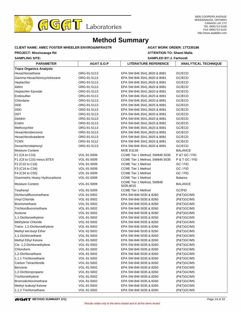
Trace Organics Analysis
Hexachloroethane ORG-91-5113 EPA SW-846 3541,3620 & 8081 GC/ECD
Gamma-Hexachlorocyclohexane ORG-91-5113 EPA SW-846 3541,3620 & 8081 GC/ECD
Heptachlor ORG-91-5113 EPA SW-846 3541,3620 & 8081 GC/ECD
Aldrin ORG-91-5113 EPA SW-846 3541,3620 & 8081 GC/ECD
Heptachlor Epoxide ORG-91-5113 EPA SW-846 3541,3620 & 8081 GC/ECD
Endosulfan ORG-91-5113 EPA SW-846 3541,3620 & 8081 GC/ECD
Chlordane ORG-91-5113 EPA SW-846 3541,3620 & 8081 GC/ECD
DDE ORG-91-5113 EPA SW-846 3541,3620 & 8081 GC/ECD
DDD ORG-91-5113 EPA SW-846 3541,3620 & 8081 GC/ECD
DDT ORG-91-5113 EPA SW-846 3541,3620 & 8081 GC/ECD
Dieldrin ORG-91-5113 EPA SW-846 3541,3620 & 8081 GC/ECD
Endrin ORG-91-5113 EPA SW-846 3541,3620 & 8081 GC/ECD
Methoxychlor ORG-91-5113 EPA SW-846 3541,3620 & 8081 GC/ECD
Hexachlorobenzene ORG-91-5113 EPA SW-846 3541,3620 & 8081 GC/ECD
Hexachlorobutadiene ORG-91-5113 EPA SW-846 3541,3620 & 8081 GC/ECD
TCMX ORG-91-5112 EPA SW-846 3541,3620 & 8081 GC/ECD
Decachlorobiphenyl ORG-91-5113 EPA SW-846 3541,3620 & 8081 GC/ECD
Moisture Content MOE E3139 BALANCE
F1 (C6 to C10) VOL-91-5009 CCME Tier 1 Method, SW846 5035 P &T GC / FID
F1 (C6 to C10) minus BTEX VOL-91-5009 CCME Tier 1 Method, SW846 5035 P & T GC / FID
F2 (C10 to C16) VOL-91-5009 CCME Tier 1 Method GC / FID
F3 (C16 to C34) VOL-91-5009 CCME Tier 1 Method GC / FID
F4 (C34 to C50) VOL-91-5009 CCME Tier 1 Method GC / FID
Gravimetric Heavy Hydrocarbons VOL-91-5009 CCME Tier 1 Method Balance
Moisture Content VOL-91-5009CCME Tier 1 Method, SW846 5035,8015
BALANCE
Terphenyl VOL-91-5009 CCME Tier 1 Method GC/FID
Dichlorodifluoromethane VOL-91-5002 EPA SW-846 5035 & 8260 (P&T)GC/MS
Vinyl Chloride VOL-91-5002 EPA SW-846 5035 & 8260 (P&T)GC/MS
Bromomethane VOL-91-5002 EPA SW-846 5035 & 8260 (P&T)GC/MS
Trichlorofluoromethane VOL-91-5002 EPA SW-846 5035 & 8260 (P&T)GC/MS
Acetone VOL-91-5002 EPA SW-846 5035 & 8260 (P&T)GC/MS
1,1-Dichloroethylene VOL-91-5002 EPA SW-846 5035 & 8260 (P&T)GC/MS
Methylene Chloride VOL-91-5002 EPA SW-846 5035 & 8260 (P&T)GC/MS
Trans- 1,2-Dichloroethylene VOL-91-5002 EPA SW-846 5035 & 8260 (P&T)GC/MS
Methyl tert-butyl Ether VOL-91-5002 EPA SW-846 5035 & 8260 (P&T)GC/MS
1,1-Dichloroethane VOL-91-5002 EPA SW-846 5035 & 8260 (P&T)GC/MS
Methyl Ethyl Ketone VOL-91-5002 EPA SW-846 5035 & 8260 (P&T)GC/MS
Cis- 1,2-Dichloroethylene VOL-91-5002 EPA SW-846 5035 & 8260 (P&T)GC/MS
Chloroform VOL-91-5002 EPA SW-846 5035 & 8260 (P&T)GC/MS
1,2-Dichloroethane VOL-91-5002 EPA SW-846 5035 & 8260 (P&T)GC/MS
1,1,1-Trichloroethane VOL-91-5002 EPA SW-846 5035 & 8260 (P&T)GC/MS
Carbon Tetrachloride VOL-91-5002 EPA SW-846 5035 & 8260 (P&T)GC/MS
Benzene VOL-91-5002 EPA SW-846 5035 & 8260 (P&T)GC/MS
1,2-Dichloropropane VOL-91-5002 EPA SW-846 5035 & 8260 (P&T)GC/MS
Trichloroethylene VOL-91-5002 EPA SW-846 5035 & 8260 (P&T)GC/MS
Bromodichloromethane VOL-91-5002 EPA SW-846 5035 & 8260 (P&T)GC/MS
Methyl Isobutyl Ketone VOL-91-5002 EPA SW-846 5035 & 8260 (P&T)GC/MS
1,1,2-Trichloroethane VOL-91-5002 EPA SW-846 5035 & 8260 (P&T)GC/MS
Results relate only to the items tested and to all the items tested
SAMPLING SITE: SAMPLED BY:J. Farhoodi
AGAT WORK ORDER: 17T230186
Method Summary
ATTENTION TO: Shami Malla
CLIENT NAME: AMEC FOSTER WHEELER ENVIRO&INFRASTR
PROJECT: Mississauga Rd
AGAT S.O.P ANALYTICAL TECHNIQUELITERATURE REFERENCEPARAMETER
5835 COOPERS AVENUEMISSISSAUGA, ONTARIO
CANADA L4Z 1Y2TEL (905)712-5100FAX (905)712-5122
http://www.agatlabs.com
METHOD SUMMARY (V1) Page 14 of 16
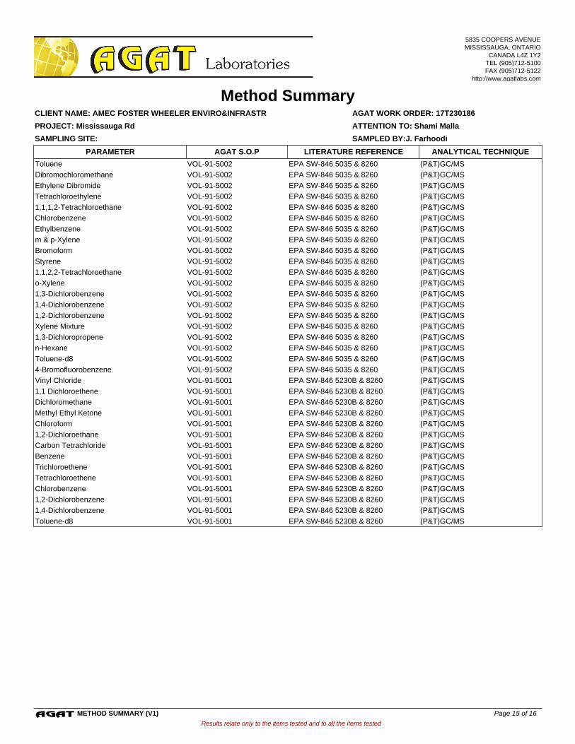
Toluene VOL-91-5002 EPA SW-846 5035 & 8260 (P&T)GC/MS
Dibromochloromethane VOL-91-5002 EPA SW-846 5035 & 8260 (P&T)GC/MS
Ethylene Dibromide VOL-91-5002 EPA SW-846 5035 & 8260 (P&T)GC/MS
Tetrachloroethylene VOL-91-5002 EPA SW-846 5035 & 8260 (P&T)GC/MS
1,1,1,2-Tetrachloroethane VOL-91-5002 EPA SW-846 5035 & 8260 (P&T)GC/MS
Chlorobenzene VOL-91-5002 EPA SW-846 5035 & 8260 (P&T)GC/MS
Ethylbenzene VOL-91-5002 EPA SW-846 5035 & 8260 (P&T)GC/MS
m & p-Xylene VOL-91-5002 EPA SW-846 5035 & 8260 (P&T)GC/MS
Bromoform VOL-91-5002 EPA SW-846 5035 & 8260 (P&T)GC/MS
Styrene VOL-91-5002 EPA SW-846 5035 & 8260 (P&T)GC/MS
1,1,2,2-Tetrachloroethane VOL-91-5002 EPA SW-846 5035 & 8260 (P&T)GC/MS
o-Xylene VOL-91-5002 EPA SW-846 5035 & 8260 (P&T)GC/MS
1,3-Dichlorobenzene VOL-91-5002 EPA SW-846 5035 & 8260 (P&T)GC/MS
1,4-Dichlorobenzene VOL-91-5002 EPA SW-846 5035 & 8260 (P&T)GC/MS
1,2-Dichlorobenzene VOL-91-5002 EPA SW-846 5035 & 8260 (P&T)GC/MS
Xylene Mixture VOL-91-5002 EPA SW-846 5035 & 8260 (P&T)GC/MS
1,3-Dichloropropene VOL-91-5002 EPA SW-846 5035 & 8260 (P&T)GC/MS
n-Hexane VOL-91-5002 EPA SW-846 5035 & 8260 (P&T)GC/MS
Toluene-d8 VOL-91-5002 EPA SW-846 5035 & 8260 (P&T)GC/MS
4-Bromofluorobenzene VOL-91-5002 EPA SW-846 5035 & 8260 (P&T)GC/MS
Vinyl Chloride VOL-91-5001 EPA SW-846 5230B & 8260 (P&T)GC/MS
1,1 Dichloroethene VOL-91-5001 EPA SW-846 5230B & 8260 (P&T)GC/MS
Dichloromethane VOL-91-5001 EPA SW-846 5230B & 8260 (P&T)GC/MS
Methyl Ethyl Ketone VOL-91-5001 EPA SW-846 5230B & 8260 (P&T)GC/MS
Chloroform VOL-91-5001 EPA SW-846 5230B & 8260 (P&T)GC/MS
1,2-Dichloroethane VOL-91-5001 EPA SW-846 5230B & 8260 (P&T)GC/MS
Carbon Tetrachloride VOL-91-5001 EPA SW-846 5230B & 8260 (P&T)GC/MS
Benzene VOL-91-5001 EPA SW-846 5230B & 8260 (P&T)GC/MS
Trichloroethene VOL-91-5001 EPA SW-846 5230B & 8260 (P&T)GC/MS
Tetrachloroethene VOL-91-5001 EPA SW-846 5230B & 8260 (P&T)GC/MS
Chlorobenzene VOL-91-5001 EPA SW-846 5230B & 8260 (P&T)GC/MS
1,2-Dichlorobenzene VOL-91-5001 EPA SW-846 5230B & 8260 (P&T)GC/MS
1,4-Dichlorobenzene VOL-91-5001 EPA SW-846 5230B & 8260 (P&T)GC/MS
Toluene-d8 VOL-91-5001 EPA SW-846 5230B & 8260 (P&T)GC/MS
Results relate only to the items tested and to all the items tested
SAMPLING SITE: SAMPLED BY:J. Farhoodi
AGAT WORK ORDER: 17T230186
Method Summary
ATTENTION TO: Shami Malla
CLIENT NAME: AMEC FOSTER WHEELER ENVIRO&INFRASTR
PROJECT: Mississauga Rd
AGAT S.O.P ANALYTICAL TECHNIQUELITERATURE REFERENCEPARAMETER
5835 COOPERS AVENUEMISSISSAUGA, ONTARIO
CANADA L4Z 1Y2TEL (905)712-5100FAX (905)712-5122
http://www.agatlabs.com
METHOD SUMMARY (V1) Page 15 of 16
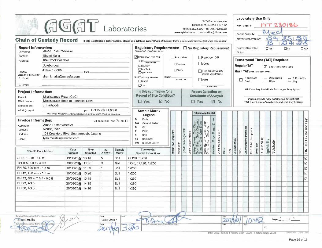
Page 16 of 16
CLIENT NAME: AMEC FOSTER WHEELER ENVIRO&INFRASTR104 CROCKFORD BLVDSCARBOROUGH, ON M1R3C3 (416) 751-6565
5835 COOPERS AVENUEMISSISSAUGA, ONTARIO
CANADA L4Z 1Y2TEL (905)712-5100FAX (905)712-5122
http://www.agatlabs.com
Yris Verastegui, Report ReviewerSOIL ANALYSIS REVIEWED BY:
Gyulhan Yalamova, Report ReviewerTRACE ORGANICS REVIEWED BY:
DATE REPORTED:
PAGES (INCLUDING COVER): 7
Aug 23, 2017
VERSION*: 1
Should you require any information regarding this analysis please contact your client services representative at (905) 712-5100
17T251600AGAT WORK ORDER:
ATTENTION TO: Shami Malla
PROJECT: Mississauga Rd. EA
Laboratories (V1) Page 1 of 7
All samples will be disposed of within 30 days following analysis. Please contact the lab if you require additional sample storage time.
AGAT Laboratories is accredited to ISO/IEC 17025 by the Canadian Association for Laboratory Accreditation Inc. (CALA) and/or Standards Council of Canada (SCC) for specific tests listed on the scope of accreditation. AGAT Laboratories (Mississauga) is also accredited by the Canadian Association for Laboratory Accreditation Inc. (CALA) for specific drinking water tests. Accreditations are location and parameter specific. A complete listing of parameters for each location is available from www.cala.ca and/or www.scc.ca. The tests in this report may not necessarily be included in the scope of accreditation.
Association of Professional Engineers and Geoscientists of Alberta (APEGA)Western Enviro-Agricultural Laboratory Association (WEALA)Environmental Services Association of Alberta (ESAA)
Member of:
*NOTES
Results relate only to the items tested and to all the items testedAll reportable information as specified by ISO 17025:2005 is available from AGAT Laboratories upon request
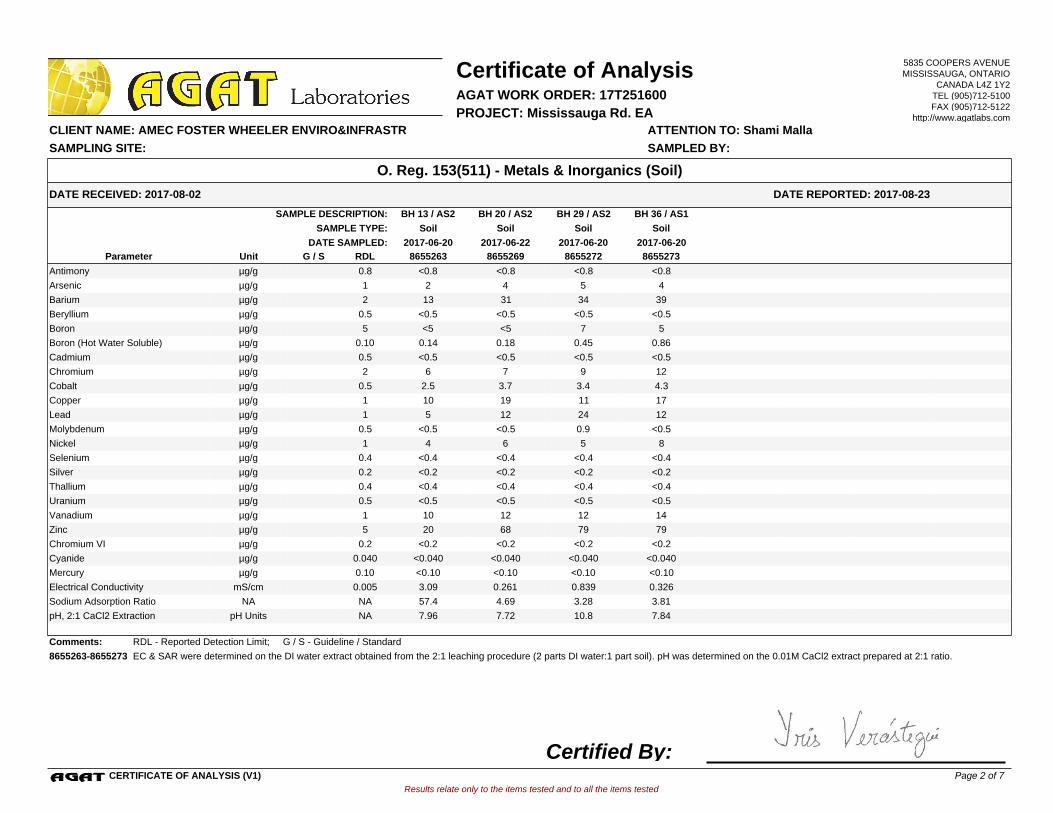
BH 20 / AS2BH 13 / AS2 BH 29 / AS2 BH 36 / AS1SAMPLE DESCRIPTION:
SoilSoilSoil SoilSAMPLE TYPE:
2017-06-22 2017-06-20 2017-06-202017-06-20DATE SAMPLED:
8655263 8655269 8655272 8655273G / S RDLUnitParameter
<0.8 <0.8 <0.8 <0.8Antimony 0.8µg/g
2 4 5 4Arsenic 1µg/g
13 31 34 39Barium 2µg/g
<0.5 <0.5 <0.5 <0.5Beryllium 0.5µg/g
<5 <5 7 5Boron 5µg/g
0.14 0.18 0.45 0.86Boron (Hot Water Soluble) 0.10µg/g
<0.5 <0.5 <0.5 <0.5Cadmium 0.5µg/g
6 7 9 12Chromium 2µg/g
2.5 3.7 3.4 4.3Cobalt 0.5µg/g
10 19 11 17Copper 1µg/g
5 12 24 12Lead 1µg/g
<0.5 <0.5 0.9 <0.5Molybdenum 0.5µg/g
4 6 5 8Nickel 1µg/g
<0.4 <0.4 <0.4 <0.4Selenium 0.4µg/g
<0.2 <0.2 <0.2 <0.2Silver 0.2µg/g
<0.4 <0.4 <0.4 <0.4Thallium 0.4µg/g
<0.5 <0.5 <0.5 <0.5Uranium 0.5µg/g
10 12 12 14Vanadium 1µg/g
20 68 79 79Zinc 5µg/g
<0.2 <0.2 <0.2 <0.2Chromium VI 0.2µg/g
<0.040 <0.040 <0.040 <0.040Cyanide 0.040µg/g
<0.10 <0.10 <0.10 <0.10Mercury 0.10µg/g
3.09 0.261 0.839 0.326Electrical Conductivity 0.005mS/cm
57.4 4.69 3.28 3.81Sodium Adsorption Ratio NANA
7.96 7.72 10.8 7.84pH, 2:1 CaCl2 Extraction NApH Units
Comments: RDL - Reported Detection Limit; G / S - Guideline / Standard
8655263-8655273 EC & SAR were determined on the DI water extract obtained from the 2:1 leaching procedure (2 parts DI water:1 part soil). pH was determined on the 0.01M CaCl2 extract prepared at 2:1 ratio.
Results relate only to the items tested and to all the items tested
DATE RECEIVED: 2017-08-02
Certificate of Analysis
ATTENTION TO: Shami Malla CLIENT NAME: AMEC FOSTER WHEELER ENVIRO&INFRASTR
AGAT WORK ORDER: 17T251600
DATE REPORTED: 2017-08-23
PROJECT: Mississauga Rd. EA
O. Reg. 153(511) - Metals & Inorganics (Soil)
SAMPLED BY:SAMPLING SITE:
5835 COOPERS AVENUEMISSISSAUGA, ONTARIO
CANADA L4Z 1Y2TEL (905)712-5100FAX (905)712-5122
http://www.agatlabs.com
CERTIFICATE OF ANALYSIS (V1)
Certified By:Page 2 of 7
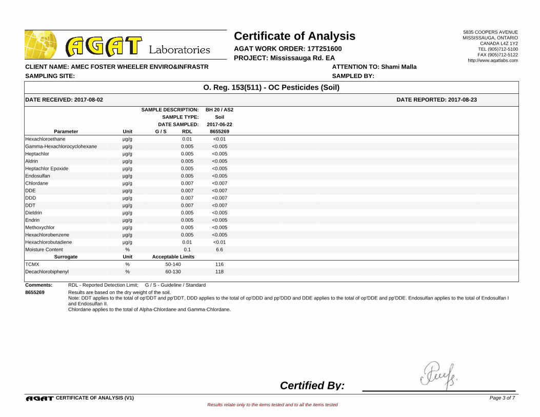
BH 20 / AS2SAMPLE DESCRIPTION:
SoilSAMPLE TYPE:
2017-06-22DATE SAMPLED:
8655269G / S RDLUnitParameter
<0.01Hexachloroethane 0.01µg/g
<0.005Gamma-Hexachlorocyclohexane 0.005µg/g
<0.005Heptachlor 0.005µg/g
<0.005Aldrin 0.005µg/g
<0.005Heptachlor Epoxide 0.005µg/g
<0.005Endosulfan 0.005µg/g
<0.007Chlordane 0.007µg/g
<0.007DDE 0.007µg/g
<0.007DDD 0.007µg/g
<0.007DDT 0.007µg/g
<0.005Dieldrin 0.005µg/g
<0.005Endrin 0.005µg/g
<0.005Methoxychlor 0.005µg/g
<0.005Hexachlorobenzene 0.005µg/g
<0.01Hexachlorobutadiene 0.01µg/g
6.6Moisture Content 0.1%
Acceptable LimitsUnitSurrogate
116TCMX % 50-140
118Decachlorobiphenyl % 60-130
Comments: RDL - Reported Detection Limit; G / S - Guideline / Standard
8655269 Results are based on the dry weight of the soil.Note: DDT applies to the total of op'DDT and pp'DDT, DDD applies to the total of op'DDD and pp'DDD and DDE applies to the total of op'DDE and pp'DDE. Endosulfan applies to the total of Endosulfan I and Endosulfan II.Chlordane applies to the total of Alpha-Chlordane and Gamma-Chlordane.
Results relate only to the items tested and to all the items tested
DATE RECEIVED: 2017-08-02
Certificate of Analysis
ATTENTION TO: Shami Malla CLIENT NAME: AMEC FOSTER WHEELER ENVIRO&INFRASTR
AGAT WORK ORDER: 17T251600
DATE REPORTED: 2017-08-23
PROJECT: Mississauga Rd. EA
O. Reg. 153(511) - OC Pesticides (Soil)
SAMPLED BY:SAMPLING SITE:
5835 COOPERS AVENUEMISSISSAUGA, ONTARIO
CANADA L4Z 1Y2TEL (905)712-5100FAX (905)712-5122
http://www.agatlabs.com
CERTIFICATE OF ANALYSIS (V1)
Certified By:Page 3 of 7
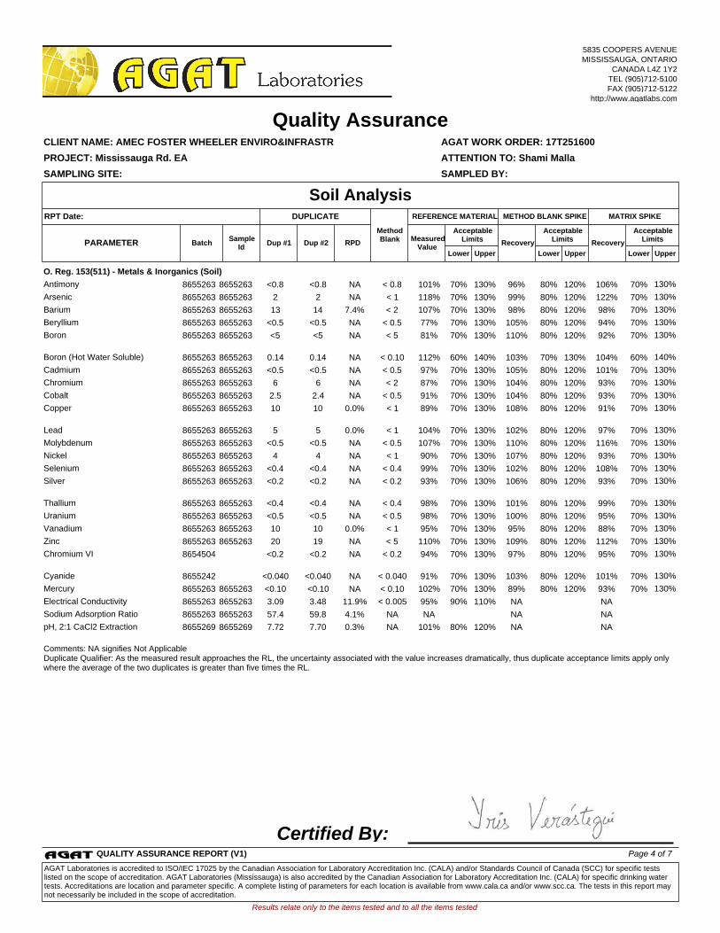
O. Reg. 153(511) - Metals & Inorganics (Soil)
Antimony 8655263 8655263 <0.8 <0.8 NA < 0.8 101% 70% 130% 96% 80% 120% 106% 70% 130%
Arsenic 8655263 8655263 2 2 NA < 1 118% 70% 130% 99% 80% 120% 122% 70% 130%
Barium 8655263 8655263 13 14 7.4% < 2 107% 70% 130% 98% 80% 120% 98% 70% 130%
Beryllium 8655263 8655263 <0.5 <0.5 NA < 0.5 77% 70% 130% 105% 80% 120% 94% 70% 130%
Boron
8655263 8655263 <5 <5 NA < 5 81% 70% 130% 110% 80% 120% 92% 70% 130%
Boron (Hot Water Soluble) 8655263 8655263 0.14 0.14 NA < 0.10 112% 60% 140% 103% 70% 130% 104% 60% 140%
Cadmium 8655263 8655263 <0.5 <0.5 NA < 0.5 97% 70% 130% 105% 80% 120% 101% 70% 130%
Chromium 8655263 8655263 6 6 NA < 2 87% 70% 130% 104% 80% 120% 93% 70% 130%
Cobalt 8655263 8655263 2.5 2.4 NA < 0.5 91% 70% 130% 104% 80% 120% 93% 70% 130%
Copper
8655263 8655263 10 10 0.0% < 1 89% 70% 130% 108% 80% 120% 91% 70% 130%
Lead 8655263 8655263 5 5 0.0% < 1 104% 70% 130% 102% 80% 120% 97% 70% 130%
Molybdenum 8655263 8655263 <0.5 <0.5 NA < 0.5 107% 70% 130% 110% 80% 120% 116% 70% 130%
Nickel 8655263 8655263 4 4 NA < 1 90% 70% 130% 107% 80% 120% 93% 70% 130%
Selenium 8655263 8655263 <0.4 <0.4 NA < 0.4 99% 70% 130% 102% 80% 120% 108% 70% 130%
Silver
8655263 8655263 <0.2 <0.2 NA < 0.2 93% 70% 130% 106% 80% 120% 93% 70% 130%
Thallium 8655263 8655263 <0.4 <0.4 NA < 0.4 98% 70% 130% 101% 80% 120% 99% 70% 130%
Uranium 8655263 8655263 <0.5 <0.5 NA < 0.5 98% 70% 130% 100% 80% 120% 95% 70% 130%
Vanadium 8655263 8655263 10 10 0.0% < 1 95% 70% 130% 95% 80% 120% 88% 70% 130%
Zinc 8655263 8655263 20 19 NA < 5 110% 70% 130% 109% 80% 120% 112% 70% 130%
Chromium VI
8654504 <0.2 <0.2 NA < 0.2 94% 70% 130% 97% 80% 120% 95% 70% 130%
Cyanide 8655242 <0.040 <0.040 NA < 0.040 91% 70% 130% 103% 80% 120% 101% 70% 130%
Mercury 8655263 8655263 <0.10 <0.10 NA < 0.10 102% 70% 130% 89% 80% 120% 93% 70% 130%
Electrical Conductivity 8655263 8655263 3.09 3.48 11.9% < 0.005 95% 90% 110% NA NA
Sodium Adsorption Ratio 8655263 8655263 57.4 59.8 4.1% NA NA NA NA
pH, 2:1 CaCl2 Extraction
8655269 8655269 7.72 7.70 0.3% NA 101% 80% 120% NA NA
Comments: NA signifies Not ApplicableDuplicate Qualifier: As the measured result approaches the RL, the uncertainty associated with the value increases dramatically, thus duplicate acceptance limits apply only where the average of the two duplicates is greater than five times the RL.
Certified By:
Results relate only to the items tested and to all the items tested
SAMPLING SITE: SAMPLED BY:
AGAT WORK ORDER: 17T251600
Dup #1 RPDMeasured
ValueRecovery Recovery
Quality Assurance
ATTENTION TO: Shami Malla
CLIENT NAME: AMEC FOSTER WHEELER ENVIRO&INFRASTR
PROJECT: Mississauga Rd. EA
Soil Analysis
UpperLower
AcceptableLimits
BatchPARAMETERSample
IdDup #2
UpperLower
AcceptableLimits
UpperLower
AcceptableLimits
MATRIX SPIKEMETHOD BLANK SPIKEDUPLICATERPT Date: REFERENCE MATERIAL
MethodBlank
5835 COOPERS AVENUEMISSISSAUGA, ONTARIO
CANADA L4Z 1Y2TEL (905)712-5100FAX (905)712-5122
http://www.agatlabs.com
QUALITY ASSURANCE REPORT (V1) Page 4 of 7
AGAT Laboratories is accredited to ISO/IEC 17025 by the Canadian Association for Laboratory Accreditation Inc. (CALA) and/or Standards Council of Canada (SCC) for specific tests listed on the scope of accreditation. AGAT Laboratories (Mississauga) is also accredited by the Canadian Association for Laboratory Accreditation Inc. (CALA) for specific drinking water tests. Accreditations are location and parameter specific. A complete listing of parameters for each location is available from www.cala.ca and/or www.scc.ca. The tests in this report may not necessarily be included in the scope of accreditation.
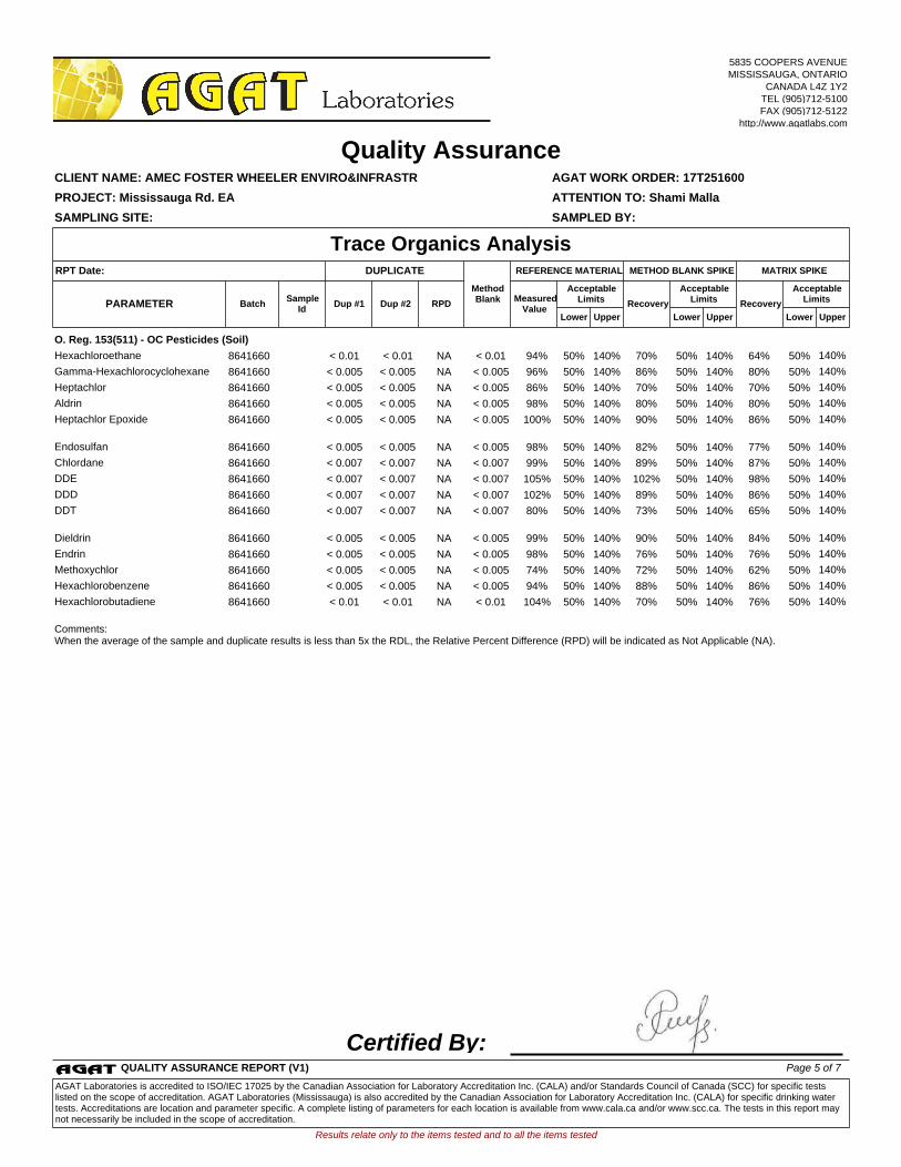
O. Reg. 153(511) - OC Pesticides (Soil)
Hexachloroethane 8641660 < 0.01 < 0.01 NA < 0.01 94% 50% 140% 70% 50% 140% 64% 50% 140%
Gamma-Hexachlorocyclohexane 8641660 < 0.005 < 0.005 NA < 0.005 96% 50% 140% 86% 50% 140% 80% 50% 140%
Heptachlor 8641660 < 0.005 < 0.005 NA < 0.005 86% 50% 140% 70% 50% 140% 70% 50% 140%
Aldrin 8641660 < 0.005 < 0.005 NA < 0.005 98% 50% 140% 80% 50% 140% 80% 50% 140%
Heptachlor Epoxide
8641660 < 0.005 < 0.005 NA < 0.005 100% 50% 140% 90% 50% 140% 86% 50% 140%
Endosulfan 8641660 < 0.005 < 0.005 NA < 0.005 98% 50% 140% 82% 50% 140% 77% 50% 140%
Chlordane 8641660 < 0.007 < 0.007 NA < 0.007 99% 50% 140% 89% 50% 140% 87% 50% 140%
DDE 8641660 < 0.007 < 0.007 NA < 0.007 105% 50% 140% 102% 50% 140% 98% 50% 140%
DDD 8641660 < 0.007 < 0.007 NA < 0.007 102% 50% 140% 89% 50% 140% 86% 50% 140%
DDT
8641660 < 0.007 < 0.007 NA < 0.007 80% 50% 140% 73% 50% 140% 65% 50% 140%
Dieldrin 8641660 < 0.005 < 0.005 NA < 0.005 99% 50% 140% 90% 50% 140% 84% 50% 140%
Endrin 8641660 < 0.005 < 0.005 NA < 0.005 98% 50% 140% 76% 50% 140% 76% 50% 140%
Methoxychlor 8641660 < 0.005 < 0.005 NA < 0.005 74% 50% 140% 72% 50% 140% 62% 50% 140%
Hexachlorobenzene 8641660 < 0.005 < 0.005 NA < 0.005 94% 50% 140% 88% 50% 140% 86% 50% 140%
Hexachlorobutadiene
8641660 < 0.01 < 0.01 NA < 0.01 104% 50% 140% 70% 50% 140% 76% 50% 140%
Comments: When the average of the sample and duplicate results is less than 5x the RDL, the Relative Percent Difference (RPD) will be indicated as Not Applicable (NA).
Certified By:
Results relate only to the items tested and to all the items tested
SAMPLING SITE: SAMPLED BY:
AGAT WORK ORDER: 17T251600
Dup #1 RPDMeasured
ValueRecovery Recovery
Quality Assurance
ATTENTION TO: Shami Malla
CLIENT NAME: AMEC FOSTER WHEELER ENVIRO&INFRASTR
PROJECT: Mississauga Rd. EA
Trace Organics Analysis
UpperLower
AcceptableLimits
BatchPARAMETERSample
IdDup #2
UpperLower
AcceptableLimits
UpperLower
AcceptableLimits
MATRIX SPIKEMETHOD BLANK SPIKEDUPLICATERPT Date: REFERENCE MATERIAL
MethodBlank
5835 COOPERS AVENUEMISSISSAUGA, ONTARIO
CANADA L4Z 1Y2TEL (905)712-5100FAX (905)712-5122
http://www.agatlabs.com
QUALITY ASSURANCE REPORT (V1) Page 5 of 7
AGAT Laboratories is accredited to ISO/IEC 17025 by the Canadian Association for Laboratory Accreditation Inc. (CALA) and/or Standards Council of Canada (SCC) for specific tests listed on the scope of accreditation. AGAT Laboratories (Mississauga) is also accredited by the Canadian Association for Laboratory Accreditation Inc. (CALA) for specific drinking water tests. Accreditations are location and parameter specific. A complete listing of parameters for each location is available from www.cala.ca and/or www.scc.ca. The tests in this report may not necessarily be included in the scope of accreditation.
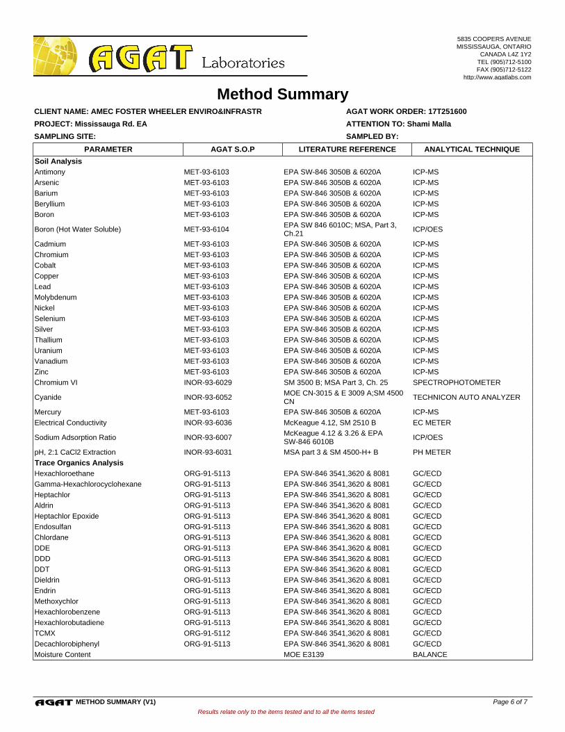
Soil Analysis
Antimony MET-93-6103 EPA SW-846 3050B & 6020A ICP-MS
Arsenic MET-93-6103 EPA SW-846 3050B & 6020A ICP-MS
Barium MET-93-6103 EPA SW-846 3050B & 6020A ICP-MS
Beryllium MET-93-6103 EPA SW-846 3050B & 6020A ICP-MS
Boron MET-93-6103 EPA SW-846 3050B & 6020A ICP-MS
Boron (Hot Water Soluble) MET-93-6104EPA SW 846 6010C; MSA, Part 3, Ch.21
ICP/OES
Cadmium MET-93-6103 EPA SW-846 3050B & 6020A ICP-MS
Chromium MET-93-6103 EPA SW-846 3050B & 6020A ICP-MS
Cobalt MET-93-6103 EPA SW-846 3050B & 6020A ICP-MS
Copper MET-93-6103 EPA SW-846 3050B & 6020A ICP-MS
Lead MET-93-6103 EPA SW-846 3050B & 6020A ICP-MS
Molybdenum MET-93-6103 EPA SW-846 3050B & 6020A ICP-MS
Nickel MET-93-6103 EPA SW-846 3050B & 6020A ICP-MS
Selenium MET-93-6103 EPA SW-846 3050B & 6020A ICP-MS
Silver MET-93-6103 EPA SW-846 3050B & 6020A ICP-MS
Thallium MET-93-6103 EPA SW-846 3050B & 6020A ICP-MS
Uranium MET-93-6103 EPA SW-846 3050B & 6020A ICP-MS
Vanadium MET-93-6103 EPA SW-846 3050B & 6020A ICP-MS
Zinc MET-93-6103 EPA SW-846 3050B & 6020A ICP-MS
Chromium VI INOR-93-6029 SM 3500 B; MSA Part 3, Ch. 25 SPECTROPHOTOMETER
Cyanide INOR-93-6052MOE CN-3015 & E 3009 A;SM 4500 CN
TECHNICON AUTO ANALYZER
Mercury MET-93-6103 EPA SW-846 3050B & 6020A ICP-MS
Electrical Conductivity INOR-93-6036 McKeague 4.12, SM 2510 B EC METER
Sodium Adsorption Ratio INOR-93-6007McKeague 4.12 & 3.26 & EPA SW-846 6010B
ICP/OES
pH, 2:1 CaCl2 Extraction INOR-93-6031 MSA part 3 & SM 4500-H+ B PH METER
Trace Organics Analysis
Hexachloroethane ORG-91-5113 EPA SW-846 3541,3620 & 8081 GC/ECD
Gamma-Hexachlorocyclohexane ORG-91-5113 EPA SW-846 3541,3620 & 8081 GC/ECD
Heptachlor ORG-91-5113 EPA SW-846 3541,3620 & 8081 GC/ECD
Aldrin ORG-91-5113 EPA SW-846 3541,3620 & 8081 GC/ECD
Heptachlor Epoxide ORG-91-5113 EPA SW-846 3541,3620 & 8081 GC/ECD
Endosulfan ORG-91-5113 EPA SW-846 3541,3620 & 8081 GC/ECD
Chlordane ORG-91-5113 EPA SW-846 3541,3620 & 8081 GC/ECD
DDE ORG-91-5113 EPA SW-846 3541,3620 & 8081 GC/ECD
DDD ORG-91-5113 EPA SW-846 3541,3620 & 8081 GC/ECD
DDT ORG-91-5113 EPA SW-846 3541,3620 & 8081 GC/ECD
Dieldrin ORG-91-5113 EPA SW-846 3541,3620 & 8081 GC/ECD
Endrin ORG-91-5113 EPA SW-846 3541,3620 & 8081 GC/ECD
Methoxychlor ORG-91-5113 EPA SW-846 3541,3620 & 8081 GC/ECD
Hexachlorobenzene ORG-91-5113 EPA SW-846 3541,3620 & 8081 GC/ECD
Hexachlorobutadiene ORG-91-5113 EPA SW-846 3541,3620 & 8081 GC/ECD
TCMX ORG-91-5112 EPA SW-846 3541,3620 & 8081 GC/ECD
Decachlorobiphenyl ORG-91-5113 EPA SW-846 3541,3620 & 8081 GC/ECD
Moisture Content MOE E3139 BALANCE
Results relate only to the items tested and to all the items tested
SAMPLING SITE: SAMPLED BY:
AGAT WORK ORDER: 17T251600
Method Summary
ATTENTION TO: Shami Malla
CLIENT NAME: AMEC FOSTER WHEELER ENVIRO&INFRASTR
PROJECT: Mississauga Rd. EA
AGAT S.O.P ANALYTICAL TECHNIQUELITERATURE REFERENCEPARAMETER
5835 COOPERS AVENUEMISSISSAUGA, ONTARIO
CANADA L4Z 1Y2TEL (905)712-5100FAX (905)712-5122
http://www.agatlabs.com
METHOD SUMMARY (V1) Page 6 of 7
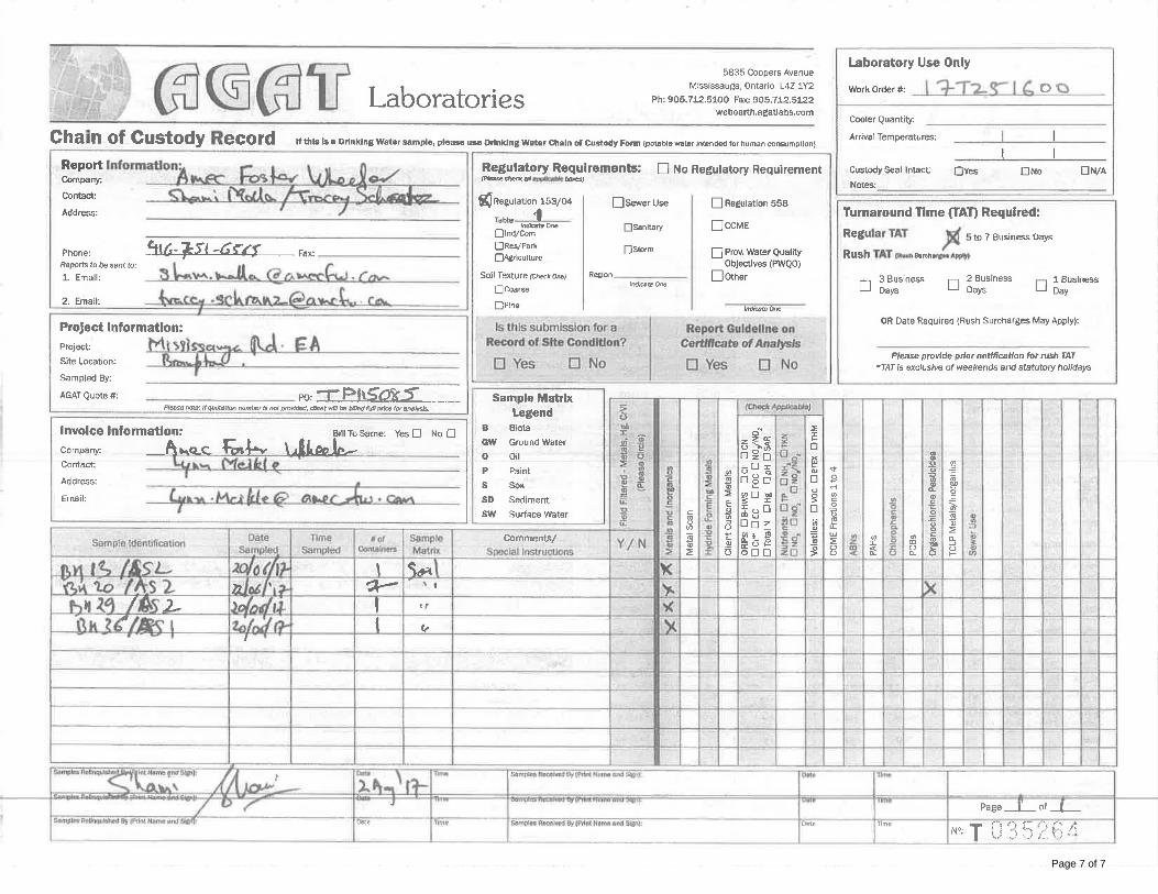
Page 7 of 7
CLIENT NAME: AMEC FOSTER WHEELER ENVIRO&INFRASTR104 CROCKFORD BLVDSCARBOROUGH, ON M1R3C3 (416) 751-6565
5835 COOPERS AVENUEMISSISSAUGA, ONTARIO
CANADA L4Z 1Y2TEL (905)712-5100FAX (905)712-5122
http://www.agatlabs.com
Amanjot Bhela, Inorganic CoordinatorSOIL ANALYSIS REVIEWED BY:
DATE REPORTED:
PAGES (INCLUDING COVER): 5
Aug 22, 2017
VERSION*: 1
Should you require any information regarding this analysis please contact your client services representative at (905) 712-5100
17T249411AGAT WORK ORDER:
ATTENTION TO: Shami Malla
PROJECT: Mississauga Road (COC)
Laboratories (V1) Page 1 of 5
All samples will be disposed of within 30 days following analysis. Please contact the lab if you require additional sample storage time.
AGAT Laboratories is accredited to ISO/IEC 17025 by the Canadian Association for Laboratory Accreditation Inc. (CALA) and/or Standards Council of Canada (SCC) for specific tests listed on the scope of accreditation. AGAT Laboratories (Mississauga) is also accredited by the Canadian Association for Laboratory Accreditation Inc. (CALA) for specific drinking water tests. Accreditations are location and parameter specific. A complete listing of parameters for each location is available from www.cala.ca and/or www.scc.ca. The tests in this report may not necessarily be included in the scope of accreditation.
Association of Professional Engineers and Geoscientists of Alberta (APEGA)Western Enviro-Agricultural Laboratory Association (WEALA)Environmental Services Association of Alberta (ESAA)
Member of:
*NOTES
Results relate only to the items tested and to all the items testedAll reportable information as specified by ISO 17025:2005 is available from AGAT Laboratories upon request
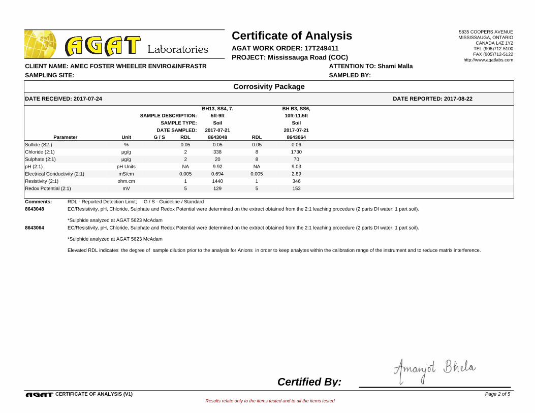
BH13, SS4, 7.
5ft-9ft
BH B3, SS6,
10ft-11.5ftSAMPLE DESCRIPTION:
SoilSoilSAMPLE TYPE:
2017-07-212017-07-21DATE SAMPLED:
8643048 RDL 8643064G / S RDLUnitParameter
0.05 0.05 0.06Sulfide (S2-) 0.05%
338 8 1730Chloride (2:1) 2µg/g
20 8 70Sulphate (2:1) 2µg/g
9.92 NA 9.03pH (2:1) NApH Units
0.694 0.005 2.89Electrical Conductivity (2:1) 0.005mS/cm
1440 1 346Resistivity (2:1) 1ohm.cm
129 5 153Redox Potential (2:1) 5mV
Comments: RDL - Reported Detection Limit; G / S - Guideline / Standard
8643048 EC/Resistivity, pH, Chloride, Sulphate and Redox Potential were determined on the extract obtained from the 2:1 leaching procedure (2 parts DI water: 1 part soil).
*Sulphide analyzed at AGAT 5623 McAdam
8643064 EC/Resistivity, pH, Chloride, Sulphate and Redox Potential were determined on the extract obtained from the 2:1 leaching procedure (2 parts DI water: 1 part soil).
*Sulphide analyzed at AGAT 5623 McAdam
Elevated RDL indicates the degree of sample dilution prior to the analysis for Anions in order to keep analytes within the calibration range of the instrument and to reduce matrix interference.
Results relate only to the items tested and to all the items tested
DATE RECEIVED: 2017-07-24
Certificate of Analysis
ATTENTION TO: Shami Malla CLIENT NAME: AMEC FOSTER WHEELER ENVIRO&INFRASTR
AGAT WORK ORDER: 17T249411
DATE REPORTED: 2017-08-22
PROJECT: Mississauga Road (COC)
Corrosivity Package
SAMPLED BY:SAMPLING SITE:
5835 COOPERS AVENUEMISSISSAUGA, ONTARIO
CANADA L4Z 1Y2TEL (905)712-5100FAX (905)712-5122
http://www.agatlabs.com
CERTIFICATE OF ANALYSIS (V1)
Certified By:Page 2 of 5
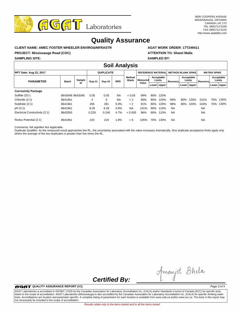
Corrosivity Package
Sulfide (S2-) 8643048 8643048 0.05 0.05 NA < 0.05 99% 80% 120%
Chloride (2:1) 8641961 4 5 NA < 2 95% 80% 120% 99% 80% 120% 101% 70% 130%
Sulphate (2:1) 8641961 265 281 5.9% < 2 91% 80% 120% 98% 80% 120% 104% 70% 130%
pH (2:1) 8641961 8.35 8.28 0.8% NA 101% 90% 110% NA NA
Electrical Conductivity (2:1)
8642550 0.229 0.240 4.7% < 0.005 96% 90% 110% NA NA
Redox Potential (2:1) 8641961 223 219 1.8% < 5 105% 70% 130% NA NA
Comments: NA signifies Not Applicable.Duplicate Qualifier: As the measured result approaches the RL, the uncertainty associated with the value increases dramatically, thus duplicate acceptance limits apply only where the average of the two duplicates is greater than five times the RL.
Certified By:
Results relate only to the items tested and to all the items tested
SAMPLING SITE: SAMPLED BY:
AGAT WORK ORDER: 17T249411
Dup #1 RPDMeasured
ValueRecovery Recovery
Quality Assurance
ATTENTION TO: Shami Malla
CLIENT NAME: AMEC FOSTER WHEELER ENVIRO&INFRASTR
PROJECT: Mississauga Road (COC)
Soil Analysis
UpperLower
AcceptableLimits
BatchPARAMETERSample
IdDup #2
UpperLower
AcceptableLimits
UpperLower
AcceptableLimits
MATRIX SPIKEMETHOD BLANK SPIKEDUPLICATERPT Date: Aug 22, 2017 REFERENCE MATERIAL
MethodBlank
5835 COOPERS AVENUEMISSISSAUGA, ONTARIO
CANADA L4Z 1Y2TEL (905)712-5100FAX (905)712-5122
http://www.agatlabs.com
QUALITY ASSURANCE REPORT (V1) Page 3 of 5
AGAT Laboratories is accredited to ISO/IEC 17025 by the Canadian Association for Laboratory Accreditation Inc. (CALA) and/or Standards Council of Canada (SCC) for specific tests listed on the scope of accreditation. AGAT Laboratories (Mississauga) is also accredited by the Canadian Association for Laboratory Accreditation Inc. (CALA) for specific drinking water tests. Accreditations are location and parameter specific. A complete listing of parameters for each location is available from www.cala.ca and/or www.scc.ca. The tests in this report may not necessarily be included in the scope of accreditation.
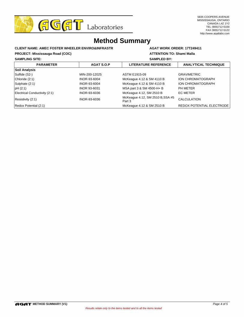
Soil Analysis
Sulfide (S2-) MIN-200-12025 ASTM E1915-09 GRAVIMETRIC
Chloride (2:1) INOR-93-6004 McKeague 4.12 & SM 4110 B ION CHROMATOGRAPH
Sulphate (2:1) INOR-93-6004 McKeague 4.12 & SM 4110 B ION CHROMATOGRAPH
pH (2:1) INOR 93-6031 MSA part 3 & SM 4500-H+ B PH METER
Electrical Conductivity (2:1) INOR-93-6036 McKeague 4.12, SM 2510 B EC METER
Resistivity (2:1) INOR-93-6036McKeague 4.12, SM 2510 B,SSA #5 Part 3
CALCULATION
Redox Potential (2:1) McKeague 4.12 & SM 2510 B REDOX POTENTIAL ELECTRODE
Results relate only to the items tested and to all the items tested
SAMPLING SITE: SAMPLED BY:
AGAT WORK ORDER: 17T249411
Method Summary
ATTENTION TO: Shami Malla
CLIENT NAME: AMEC FOSTER WHEELER ENVIRO&INFRASTR
PROJECT: Mississauga Road (COC)
AGAT S.O.P ANALYTICAL TECHNIQUELITERATURE REFERENCEPARAMETER
5835 COOPERS AVENUEMISSISSAUGA, ONTARIO
CANADA L4Z 1Y2TEL (905)712-5100FAX (905)712-5122
http://www.agatlabs.com
METHOD SUMMARY (V1) Page 4 of 5
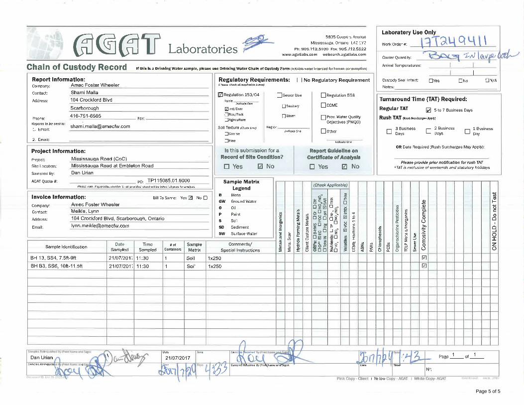
Page 5 of 5

APPENDIX DONTARIO REGULATION 347 TCLP ANDCERTIFICATE OF ANALYSIS
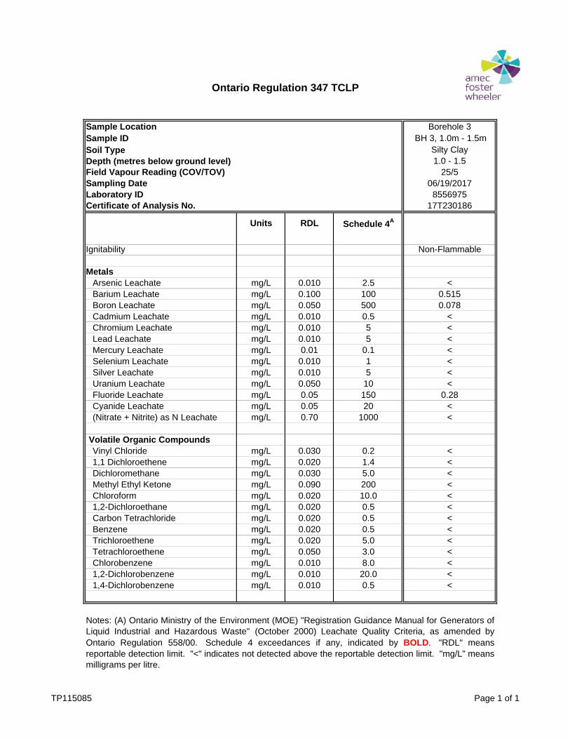
Ontario Regulation 347 TCLP
Sample Location Borehole 3Sample ID BH 3, 1.0m - 1.5m Soil Type Silty ClayDepth (metres below ground level) 1.0 - 1.5Field Vapour Reading (COV/TOV) 25/5Sampling Date 06/19/2017Laboratory ID 8556975Certificate of Analysis No. 17T230186
Units RDL Schedule 4A
Ignitability Non-Flammable
MetalsArsenic Leachate mg/L 0.010 2.5 <Barium Leachate mg/L 0.100 100 0.515Boron Leachate mg/L 0.050 500 0.078Cadmium Leachate mg/L 0.010 0.5 <Chromium Leachate mg/L 0.010 5 <Lead Leachate mg/L 0.010 5 <Mercury Leachate mg/L 0.01 0.1 <Selenium Leachate mg/L 0.010 1 <Silver Leachate mg/L 0.010 5 <Uranium Leachate mg/L 0.050 10 <Fluoride Leachate mg/L 0.05 150 0.28Cyanide Leachate mg/L 0.05 20 <(Nitrate + Nitrite) as N Leachate mg/L 0.70 1000 <
Volatile Organic CompoundsVinyl Chloride mg/L 0.030 0.2 <1,1 Dichloroethene mg/L 0.020 1.4 <Dichloromethane mg/L 0.030 5.0 <Methyl Ethyl Ketone mg/L 0.090 200 <Chloroform mg/L 0.020 10.0 <1,2-Dichloroethane mg/L 0.020 0.5 <Carbon Tetrachloride mg/L 0.020 0.5 <Benzene mg/L 0.020 0.5 <Trichloroethene mg/L 0.020 5.0 <Tetrachloroethene mg/L 0.050 3.0 <Chlorobenzene mg/L 0.010 8.0 <1,2-Dichlorobenzene mg/L 0.010 20.0 <1,4-Dichlorobenzene mg/L 0.010 0.5 <
Notes: (A) Ontario Ministry of the Environment (MOE) "Registration Guidance Manual for Generators ofLiquid Industrial and Hazardous Waste" (October 2000) Leachate Quality Criteria, as amended byOntario Regulation 558/00. Schedule 4 exceedances if any, indicated by BOLD. "RDL" meansreportable detection limit. "<" indicates not detected above the reportable detection limit. "mg/L" meansmilligrams per litre.
TP115085 Page 1 of 1
CLIENT NAME: AMEC FOSTER WHEELER ENVIRO&INFRASTR104 CROCKFORD BLVDSCARBOROUGH, ON M1R3C3 (416) 751-6565
5835 COOPERS AVENUEMISSISSAUGA, ONTARIO
CANADA L4Z 1Y2TEL (905)712-5100FAX (905)712-5122
http://www.agatlabs.com
Amanjot Bhela, Inorganic CoordinatorSOIL ANALYSIS REVIEWED BY:
Neli Popnikolova, Senior ChemistTRACE ORGANICS REVIEWED BY:
DATE REPORTED:
PAGES (INCLUDING COVER): 12
Jul 19, 2017
VERSION*: 1
Should you require any information regarding this analysis please contact your client services representative at (905) 712-5100
17T230186AGAT WORK ORDER:
ATTENTION TO: Shami Malla
PROJECT: Mississauga Rd
Laboratories (V1) Page 1 of 12
All samples will be disposed of within 30 days following analysis. Please contact the lab if you require additional sample storage time.
AGAT Laboratories is accredited to ISO/IEC 17025 by the Canadian Association for Laboratory Accreditation Inc. (CALA) and/or Standards Council of Canada (SCC) for specific tests listed on the scope of accreditation. AGAT Laboratories (Mississauga) is also accredited by the Canadian Association for Laboratory Accreditation Inc. (CALA) for specific drinking water tests. Accreditations are location and parameter specific. A complete listing of parameters for each location is available from www.cala.ca and/or www.scc.ca. The tests in this report may not necessarily be included in the scope of accreditation.
Association of Professional Engineers and Geoscientists of Alberta (APEGA)Western Enviro-Agricultural Laboratory Association (WEALA)Environmental Services Association of Alberta (ESAA)
Member of:
*NOTES
Results relate only to the items tested and to all the items testedAll reportable information as specified by ISO 17025:2005 is available from AGAT Laboratories upon request
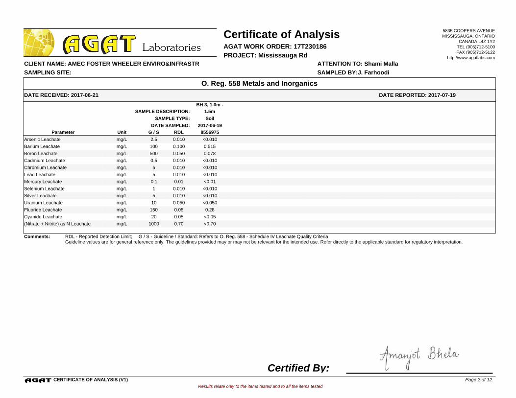
BH 3, 1.0m -
1.5mSAMPLE DESCRIPTION:
SoilSAMPLE TYPE:
2017-06-19DATE SAMPLED:
8556975G / S RDLUnitParameter
<0.010Arsenic Leachate 0.0102.5mg/L
0.515Barium Leachate 0.100100mg/L
0.078Boron Leachate 0.050500mg/L
<0.010Cadmium Leachate 0.0100.5mg/L
<0.010Chromium Leachate 0.0105mg/L
<0.010Lead Leachate 0.0105mg/L
<0.01Mercury Leachate 0.010.1mg/L
<0.010Selenium Leachate 0.0101mg/L
<0.010Silver Leachate 0.0105mg/L
<0.050Uranium Leachate 0.05010mg/L
0.28Fluoride Leachate 0.05150mg/L
<0.05Cyanide Leachate 0.0520mg/L
<0.70(Nitrate + Nitrite) as N Leachate 0.701000mg/L
Comments: RDL - Reported Detection Limit; G / S - Guideline / Standard: Refers to O. Reg. 558 - Schedule IV Leachate Quality CriteriaGuideline values are for general reference only. The guidelines provided may or may not be relevant for the intended use. Refer directly to the applicable standard for regulatory interpretation.
Results relate only to the items tested and to all the items tested
DATE RECEIVED: 2017-06-21
Certificate of Analysis
ATTENTION TO: Shami Malla CLIENT NAME: AMEC FOSTER WHEELER ENVIRO&INFRASTR
AGAT WORK ORDER: 17T230186
DATE REPORTED: 2017-07-19
PROJECT: Mississauga Rd
O. Reg. 558 Metals and Inorganics
SAMPLED BY:J. FarhoodiSAMPLING SITE:
5835 COOPERS AVENUEMISSISSAUGA, ONTARIO
CANADA L4Z 1Y2TEL (905)712-5100FAX (905)712-5122
http://www.agatlabs.com
CERTIFICATE OF ANALYSIS (V1)
Certified By:Page 2 of 12
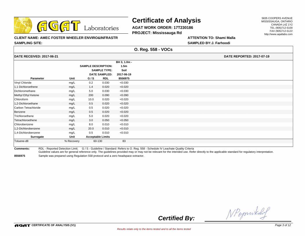
BH 3, 1.0m -
1.5mSAMPLE DESCRIPTION:
SoilSAMPLE TYPE:
2017-06-19DATE SAMPLED:
8556975G / S RDLUnitParameter
<0.030Vinyl Chloride 0.0300.2mg/L
<0.0201,1 Dichloroethene 0.0201.4mg/L
<0.030Dichloromethane 0.0305.0mg/L
<0.090Methyl Ethyl Ketone 0.090200mg/L
<0.020Chloroform 0.02010.0mg/L
<0.0201,2-Dichloroethane 0.0200.5mg/L
<0.020Carbon Tetrachloride 0.0200.5mg/L
<0.020Benzene 0.0200.5mg/L
<0.020Trichloroethene 0.0205.0mg/L
<0.050Tetrachloroethene 0.0503.0mg/L
<0.010Chlorobenzene 0.0108.0mg/L
<0.0101,2-Dichlorobenzene 0.01020.0mg/L
<0.0101,4-Dichlorobenzene 0.0100.5mg/L
Acceptable LimitsUnitSurrogate
83Toluene-d8 % Recovery 60-130
Comments: RDL - Reported Detection Limit; G / S - Guideline / Standard: Refers to O. Reg. 558 - Schedule IV Leachate Quality CriteriaGuideline values are for general reference only. The guidelines provided may or may not be relevant for the intended use. Refer directly to the applicable standard for regulatory interpretation.
8556975 Sample was prepared using Regulation 558 protocol and a zero headspace extractor.
Results relate only to the items tested and to all the items tested
DATE RECEIVED: 2017-06-21
Certificate of Analysis
ATTENTION TO: Shami Malla CLIENT NAME: AMEC FOSTER WHEELER ENVIRO&INFRASTR
AGAT WORK ORDER: 17T230186
DATE REPORTED: 2017-07-19
PROJECT: Mississauga Rd
O. Reg. 558 - VOCs
SAMPLED BY:J. FarhoodiSAMPLING SITE:
5835 COOPERS AVENUEMISSISSAUGA, ONTARIO
CANADA L4Z 1Y2TEL (905)712-5100FAX (905)712-5122
http://www.agatlabs.com
CERTIFICATE OF ANALYSIS (V1)
Certified By:Page 3 of 12
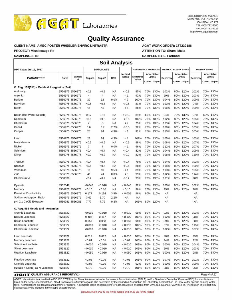
O. Reg. 153(511) - Metals & Inorganics (Soil)
Antimony 8556975 8556975 <0.8 <0.8 NA < 0.8 85% 70% 130% 102% 80% 120% 102% 70% 130%
Arsenic 8556975 8556975 4 4 NA < 1 92% 70% 130% 99% 80% 120% 103% 70% 130%
Barium 8556975 8556975 32 32 0.0% < 2 102% 70% 130% 104% 80% 120% 100% 70% 130%
Beryllium 8556975 8556975 <0.5 <0.5 NA < 0.5 81% 70% 130% 103% 80% 120% 94% 70% 130%
Boron
8556975 8556975 <5 <5 NA < 5 86% 70% 130% 106% 80% 120% 100% 70% 130%
Boron (Hot Water Soluble) 8556975 8556975 0.17 0.15 NA < 0.10 84% 60% 140% 94% 70% 130% 97% 60% 140%
Cadmium 8556975 8556975 <0.5 <0.5 NA < 0.5 102% 70% 130% 102% 80% 120% 105% 70% 130%
Chromium 8556975 8556975 7 8 NA < 2 75% 70% 130% 105% 80% 120% 104% 70% 130%
Cobalt 8556975 8556975 3.6 3.7 2.7% < 0.5 92% 70% 130% 106% 80% 120% 103% 70% 130%
Copper
8556975 8556975 23 24 4.3% < 1 91% 70% 130% 110% 80% 120% 105% 70% 130%
Lead 8556975 8556975 23 24 4.3% < 1 101% 70% 130% 105% 80% 120% 103% 70% 130%
Molybdenum 8556975 8556975 <0.5 <0.5 NA < 0.5 88% 70% 130% 108% 80% 120% 107% 70% 130%
Nickel 8556975 8556975 7 7 0.0% < 1 96% 70% 130% 112% 80% 120% 107% 70% 130%
Selenium 8556975 8556975 <0.4 <0.4 NA < 0.4 82% 70% 130% 104% 80% 120% 109% 70% 130%
Silver
8556975 8556975 <0.2 <0.2 NA < 0.2 82% 70% 130% 106% 80% 120% 110% 70% 130%
Thallium 8556975 8556975 <0.4 <0.4 NA < 0.4 79% 70% 130% 104% 80% 120% 102% 70% 130%
Uranium 8556975 8556975 <0.5 <0.5 NA < 0.5 88% 70% 130% 105% 80% 120% 100% 70% 130%
Vanadium 8556975 8556975 11 10 9.5% < 1 89% 70% 130% 103% 80% 120% 105% 70% 130%
Zinc 8556975 8556975 41 41 0.0% < 5 99% 70% 130% 112% 80% 120% 114% 70% 130%
Chromium VI
8558036 <0.2 <0.2 NA < 0.2 93% 70% 130% 101% 80% 120% 98% 70% 130%
Cyanide 8552648 <0.040 <0.040 NA < 0.040 92% 70% 130% 100% 80% 120% 102% 70% 130%
Mercury 8556975 8556975 <0.10 <0.10 NA < 0.10 96% 70% 130% 95% 80% 120% 98% 70% 130%
Electrical Conductivity 8556975 8556975 0.177 0.184 3.9% < 0.005 96% 90% 110% NA NA
Sodium Adsorption Ratio 8556975 8556975 3.62 3.70 2.2% NA NA NA NA
pH, 2:1 CaCl2 Extraction
8556981 8556981 7.77 7.79 0.3% NA 101% 80% 120% NA NA
O. Reg. 558 Metals and Inorganics
Arsenic Leachate 8553822 <0.010 <0.010 NA < 0.010 99% 90% 110% 92% 80% 120% 103% 70% 130%
Barium Leachate 8553822 0.495 0.467 NA < 0.100 103% 90% 110% 102% 80% 120% 98% 70% 130%
Boron Leachate 8553822 0.057 0.058 NA < 0.050 98% 90% 110% 99% 80% 120% 88% 70% 130%
Cadmium Leachate 8553822 <0.010 <0.010 NA < 0.010 102% 90% 110% 97% 80% 120% 115% 70% 130%
Chromium Leachate
8553822 <0.010 <0.010 NA < 0.010 103% 90% 110% 102% 80% 120% 107% 70% 130%
Lead Leachate 8553822 0.012 0.012 NA < 0.010 103% 90% 110% 98% 80% 120% 95% 70% 130%
Mercury Leachate 8553822 <0.01 <0.01 NA < 0.01 100% 90% 110% 94% 80% 120% 92% 70% 130%
Selenium Leachate 8553822 <0.010 <0.010 NA < 0.010 102% 90% 110% 100% 80% 120% 104% 70% 130%
Silver Leachate 8553822 <0.010 <0.010 NA < 0.010 103% 90% 110% 96% 80% 120% 103% 70% 130%
Uranium Leachate
8553822 <0.050 <0.050 NA < 0.050 101% 90% 110% 100% 80% 120% 98% 70% 130%
Fluoride Leachate 8553822 <0.05 <0.05 NA < 0.05 101% 90% 110% 107% 90% 110% 101% 70% 130%
Cyanide Leachate 8553822 <0.05 <0.05 NA < 0.05 92% 90% 110% 100% 90% 110% 100% 70% 130%
(Nitrate + Nitrite) as N Leachate 8553822 <0.70 <0.70 NA < 0.70 101% 80% 120% 98% 80% 120% 96% 70% 130%
Results relate only to the items tested and to all the items tested
SAMPLING SITE: SAMPLED BY:J. Farhoodi
AGAT WORK ORDER: 17T230186
Dup #1 RPDMeasured
ValueRecovery Recovery
Quality Assurance
ATTENTION TO: Shami Malla
CLIENT NAME: AMEC FOSTER WHEELER ENVIRO&INFRASTR
PROJECT: Mississauga Rd
Soil Analysis
UpperLower
AcceptableLimits
BatchPARAMETERSample
IdDup #2
UpperLower
AcceptableLimits
UpperLower
AcceptableLimits
MATRIX SPIKEMETHOD BLANK SPIKEDUPLICATERPT Date: Jul 19, 2017 REFERENCE MATERIAL
MethodBlank
5835 COOPERS AVENUEMISSISSAUGA, ONTARIO
CANADA L4Z 1Y2TEL (905)712-5100FAX (905)712-5122
http://www.agatlabs.com
QUALITY ASSURANCE REPORT (V1) Page 4 of 12
AGAT Laboratories is accredited to ISO/IEC 17025 by the Canadian Association for Laboratory Accreditation Inc. (CALA) and/or Standards Council of Canada (SCC) for specific tests listed on the scope of accreditation. AGAT Laboratories (Mississauga) is also accredited by the Canadian Association for Laboratory Accreditation Inc. (CALA) for specific drinking water tests. Accreditations are location and parameter specific. A complete listing of parameters for each location is available from www.cala.ca and/or www.scc.ca. The tests in this report may not necessarily be included in the scope of accreditation.
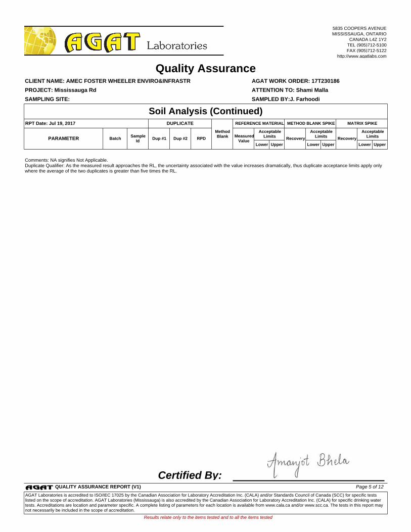
Comments: NA signifies Not Applicable.Duplicate Qualifier: As the measured result approaches the RL, the uncertainty associated with the value increases dramatically, thus duplicate acceptance limits apply only where the average of the two duplicates is greater than five times the RL.
Certified By:
Results relate only to the items tested and to all the items tested
SAMPLING SITE: SAMPLED BY:J. Farhoodi
AGAT WORK ORDER: 17T230186
Dup #1 RPDMeasured
ValueRecovery Recovery
Quality Assurance
ATTENTION TO: Shami Malla
CLIENT NAME: AMEC FOSTER WHEELER ENVIRO&INFRASTR
PROJECT: Mississauga Rd
Soil Analysis (Continued)
UpperLower
AcceptableLimits
BatchPARAMETERSample
IdDup #2
UpperLower
AcceptableLimits
UpperLower
AcceptableLimits
MATRIX SPIKEMETHOD BLANK SPIKEDUPLICATERPT Date: Jul 19, 2017 REFERENCE MATERIAL
MethodBlank
5835 COOPERS AVENUEMISSISSAUGA, ONTARIO
CANADA L4Z 1Y2TEL (905)712-5100FAX (905)712-5122
http://www.agatlabs.com
QUALITY ASSURANCE REPORT (V1) Page 5 of 12
AGAT Laboratories is accredited to ISO/IEC 17025 by the Canadian Association for Laboratory Accreditation Inc. (CALA) and/or Standards Council of Canada (SCC) for specific tests listed on the scope of accreditation. AGAT Laboratories (Mississauga) is also accredited by the Canadian Association for Laboratory Accreditation Inc. (CALA) for specific drinking water tests. Accreditations are location and parameter specific. A complete listing of parameters for each location is available from www.cala.ca and/or www.scc.ca. The tests in this report may not necessarily be included in the scope of accreditation.
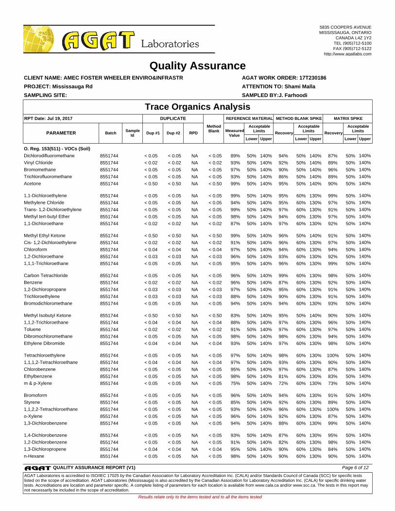
O. Reg. 153(511) - VOCs (Soil)
Dichlorodifluoromethane 8551744 < 0.05 < 0.05 NA < 0.05 89% 50% 140% 94% 50% 140% 87% 50% 140%
Vinyl Chloride 8551744 < 0.02 < 0.02 NA < 0.02 93% 50% 140% 92% 50% 140% 89% 50% 140%
Bromomethane 8551744 < 0.05 < 0.05 NA < 0.05 97% 50% 140% 90% 50% 140% 96% 50% 140%
Trichlorofluoromethane 8551744 < 0.05 < 0.05 NA < 0.05 93% 50% 140% 86% 50% 140% 89% 50% 140%
Acetone
8551744 < 0.50 < 0.50 NA < 0.50 99% 50% 140% 95% 50% 140% 90% 50% 140%
1,1-Dichloroethylene 8551744 < 0.05 < 0.05 NA < 0.05 99% 50% 140% 95% 60% 130% 99% 50% 140%
Methylene Chloride 8551744 < 0.05 < 0.05 NA < 0.05 94% 50% 140% 95% 60% 130% 97% 50% 140%
Trans- 1,2-Dichloroethylene 8551744 < 0.05 < 0.05 NA < 0.05 99% 50% 140% 97% 60% 130% 91% 50% 140%
Methyl tert-butyl Ether 8551744 < 0.05 < 0.05 NA < 0.05 98% 50% 140% 94% 60% 130% 97% 50% 140%
1,1-Dichloroethane
8551744 < 0.02 < 0.02 NA < 0.02 87% 50% 140% 97% 60% 130% 92% 50% 140%
Methyl Ethyl Ketone 8551744 < 0.50 < 0.50 NA < 0.50 99% 50% 140% 96% 50% 140% 91% 50% 140%
Cis- 1,2-Dichloroethylene 8551744 < 0.02 < 0.02 NA < 0.02 91% 50% 140% 96% 60% 130% 97% 50% 140%
Chloroform 8551744 < 0.04 < 0.04 NA < 0.04 97% 50% 140% 94% 60% 130% 94% 50% 140%
1,2-Dichloroethane 8551744 < 0.03 < 0.03 NA < 0.03 96% 50% 140% 93% 60% 130% 92% 50% 140%
1,1,1-Trichloroethane
8551744 < 0.05 < 0.05 NA < 0.05 95% 50% 140% 96% 60% 130% 99% 50% 140%
Carbon Tetrachloride 8551744 < 0.05 < 0.05 NA < 0.05 96% 50% 140% 99% 60% 130% 98% 50% 140%
Benzene 8551744 < 0.02 < 0.02 NA < 0.02 96% 50% 140% 87% 60% 130% 92% 50% 140%
1,2-Dichloropropane 8551744 < 0.03 < 0.03 NA < 0.03 97% 50% 140% 95% 60% 130% 91% 50% 140%
Trichloroethylene 8551744 < 0.03 < 0.03 NA < 0.03 88% 50% 140% 90% 60% 130% 91% 50% 140%
Bromodichloromethane
8551744 < 0.05 < 0.05 NA < 0.05 94% 50% 140% 94% 60% 130% 93% 50% 140%
Methyl Isobutyl Ketone 8551744 < 0.50 < 0.50 NA < 0.50 83% 50% 140% 95% 50% 140% 90% 50% 140%
1,1,2-Trichloroethane 8551744 < 0.04 < 0.04 NA < 0.04 88% 50% 140% 97% 60% 130% 96% 50% 140%
Toluene 8551744 < 0.02 < 0.02 NA < 0.02 91% 50% 140% 97% 60% 130% 97% 50% 140%
Dibromochloromethane 8551744 < 0.05 < 0.05 NA < 0.05 98% 50% 140% 98% 60% 130% 94% 50% 140%
Ethylene Dibromide
8551744 < 0.04 < 0.04 NA < 0.04 93% 50% 140% 97% 60% 130% 98% 50% 140%
Tetrachloroethylene 8551744 < 0.05 < 0.05 NA < 0.05 97% 50% 140% 98% 60% 130% 100% 50% 140%
1,1,1,2-Tetrachloroethane 8551744 < 0.04 < 0.04 NA < 0.04 97% 50% 140% 93% 60% 130% 90% 50% 140%
Chlorobenzene 8551744 < 0.05 < 0.05 NA < 0.05 95% 50% 140% 97% 60% 130% 87% 50% 140%
Ethylbenzene 8551744 < 0.05 < 0.05 NA < 0.05 98% 50% 140% 81% 60% 130% 83% 50% 140%
m & p-Xylene
8551744 < 0.05 < 0.05 NA < 0.05 75% 50% 140% 72% 60% 130% 73% 50% 140%
Bromoform 8551744 < 0.05 < 0.05 NA < 0.05 96% 50% 140% 94% 60% 130% 91% 50% 140%
Styrene 8551744 < 0.05 < 0.05 NA < 0.05 85% 50% 140% 92% 60% 130% 89% 50% 140%
1,1,2,2-Tetrachloroethane 8551744 < 0.05 < 0.05 NA < 0.05 93% 50% 140% 96% 60% 130% 100% 50% 140%
o-Xylene 8551744 < 0.05 < 0.05 NA < 0.05 96% 50% 140% 92% 60% 130% 87% 50% 140%
1,3-Dichlorobenzene
8551744 < 0.05 < 0.05 NA < 0.05 94% 50% 140% 88% 60% 130% 99% 50% 140%
1,4-Dichlorobenzene 8551744 < 0.05 < 0.05 NA < 0.05 93% 50% 140% 87% 60% 130% 95% 50% 140%
1,2-Dichlorobenzene 8551744 < 0.05 < 0.05 NA < 0.05 91% 50% 140% 82% 60% 130% 98% 50% 140%
1,3-Dichloropropene 8551744 < 0.04 < 0.04 NA < 0.04 95% 50% 140% 90% 60% 130% 84% 50% 140%
n-Hexane 8551744 < 0.05 < 0.05 NA < 0.05 98% 50% 140% 90% 60% 130% 90% 50% 140%
Results relate only to the items tested and to all the items tested
SAMPLING SITE: SAMPLED BY:J. Farhoodi
AGAT WORK ORDER: 17T230186
Dup #1 RPDMeasured
ValueRecovery Recovery
Quality Assurance
ATTENTION TO: Shami Malla
CLIENT NAME: AMEC FOSTER WHEELER ENVIRO&INFRASTR
PROJECT: Mississauga Rd
Trace Organics Analysis
UpperLower
AcceptableLimits
BatchPARAMETERSample
IdDup #2
UpperLower
AcceptableLimits
UpperLower
AcceptableLimits
MATRIX SPIKEMETHOD BLANK SPIKEDUPLICATERPT Date: Jul 19, 2017 REFERENCE MATERIAL
MethodBlank
5835 COOPERS AVENUEMISSISSAUGA, ONTARIO
CANADA L4Z 1Y2TEL (905)712-5100FAX (905)712-5122
http://www.agatlabs.com
QUALITY ASSURANCE REPORT (V1) Page 6 of 12
AGAT Laboratories is accredited to ISO/IEC 17025 by the Canadian Association for Laboratory Accreditation Inc. (CALA) and/or Standards Council of Canada (SCC) for specific tests listed on the scope of accreditation. AGAT Laboratories (Mississauga) is also accredited by the Canadian Association for Laboratory Accreditation Inc. (CALA) for specific drinking water tests. Accreditations are location and parameter specific. A complete listing of parameters for each location is available from www.cala.ca and/or www.scc.ca. The tests in this report may not necessarily be included in the scope of accreditation.
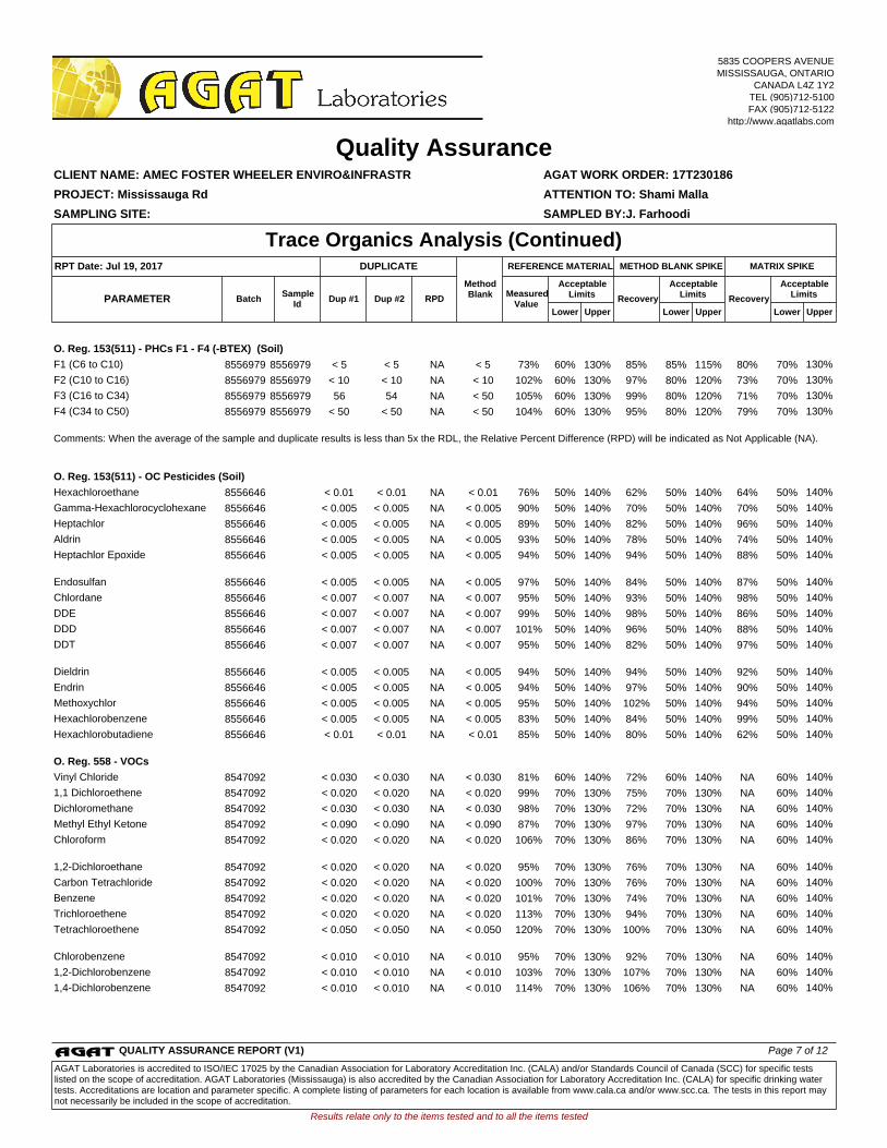
O. Reg. 153(511) - PHCs F1 - F4 (-BTEX) (Soil)
F1 (C6 to C10) 8556979 8556979 < 5 < 5 NA < 5 73% 60% 130% 85% 85% 115% 80% 70% 130%
F2 (C10 to C16) 8556979 8556979 < 10 < 10 NA < 10 102% 60% 130% 97% 80% 120% 73% 70% 130%
F3 (C16 to C34) 8556979 8556979 56 54 NA < 50 105% 60% 130% 99% 80% 120% 71% 70% 130%
F4 (C34 to C50) 8556979 8556979 < 50 < 50 NA < 50 104% 60% 130% 95% 80% 120% 79% 70% 130%
Comments: When the average of the sample and duplicate results is less than 5x the RDL, the Relative Percent Difference (RPD) will be indicated as Not Applicable (NA).
O. Reg. 153(511) - OC Pesticides (Soil)
Hexachloroethane 8556646 < 0.01 < 0.01 NA < 0.01 76% 50% 140% 62% 50% 140% 64% 50% 140%
Gamma-Hexachlorocyclohexane 8556646 < 0.005 < 0.005 NA < 0.005 90% 50% 140% 70% 50% 140% 70% 50% 140%
Heptachlor 8556646 < 0.005 < 0.005 NA < 0.005 89% 50% 140% 82% 50% 140% 96% 50% 140%
Aldrin 8556646 < 0.005 < 0.005 NA < 0.005 93% 50% 140% 78% 50% 140% 74% 50% 140%
Heptachlor Epoxide
8556646 < 0.005 < 0.005 NA < 0.005 94% 50% 140% 94% 50% 140% 88% 50% 140%
Endosulfan 8556646 < 0.005 < 0.005 NA < 0.005 97% 50% 140% 84% 50% 140% 87% 50% 140%
Chlordane 8556646 < 0.007 < 0.007 NA < 0.007 95% 50% 140% 93% 50% 140% 98% 50% 140%
DDE 8556646 < 0.007 < 0.007 NA < 0.007 99% 50% 140% 98% 50% 140% 86% 50% 140%
DDD 8556646 < 0.007 < 0.007 NA < 0.007 101% 50% 140% 96% 50% 140% 88% 50% 140%
DDT
8556646 < 0.007 < 0.007 NA < 0.007 95% 50% 140% 82% 50% 140% 97% 50% 140%
Dieldrin 8556646 < 0.005 < 0.005 NA < 0.005 94% 50% 140% 94% 50% 140% 92% 50% 140%
Endrin 8556646 < 0.005 < 0.005 NA < 0.005 94% 50% 140% 97% 50% 140% 90% 50% 140%
Methoxychlor 8556646 < 0.005 < 0.005 NA < 0.005 95% 50% 140% 102% 50% 140% 94% 50% 140%
Hexachlorobenzene 8556646 < 0.005 < 0.005 NA < 0.005 83% 50% 140% 84% 50% 140% 99% 50% 140%
Hexachlorobutadiene
8556646 < 0.01 < 0.01 NA < 0.01 85% 50% 140% 80% 50% 140% 62% 50% 140%
O. Reg. 558 - VOCs
Vinyl Chloride 8547092 < 0.030 < 0.030 NA < 0.030 81% 60% 140% 72% 60% 140% NA 60% 140%
1,1 Dichloroethene 8547092 < 0.020 < 0.020 NA < 0.020 99% 70% 130% 75% 70% 130% NA 60% 140%
Dichloromethane 8547092 < 0.030 < 0.030 NA < 0.030 98% 70% 130% 72% 70% 130% NA 60% 140%
Methyl Ethyl Ketone 8547092 < 0.090 < 0.090 NA < 0.090 87% 70% 130% 97% 70% 130% NA 60% 140%
Chloroform
8547092 < 0.020 < 0.020 NA < 0.020 106% 70% 130% 86% 70% 130% NA 60% 140%
1,2-Dichloroethane 8547092 < 0.020 < 0.020 NA < 0.020 95% 70% 130% 76% 70% 130% NA 60% 140%
Carbon Tetrachloride 8547092 < 0.020 < 0.020 NA < 0.020 100% 70% 130% 76% 70% 130% NA 60% 140%
Benzene 8547092 < 0.020 < 0.020 NA < 0.020 101% 70% 130% 74% 70% 130% NA 60% 140%
Trichloroethene 8547092 < 0.020 < 0.020 NA < 0.020 113% 70% 130% 94% 70% 130% NA 60% 140%
Tetrachloroethene
8547092 < 0.050 < 0.050 NA < 0.050 120% 70% 130% 100% 70% 130% NA 60% 140%
Chlorobenzene 8547092 < 0.010 < 0.010 NA < 0.010 95% 70% 130% 92% 70% 130% NA 60% 140%
1,2-Dichlorobenzene 8547092 < 0.010 < 0.010 NA < 0.010 103% 70% 130% 107% 70% 130% NA 60% 140%
1,4-Dichlorobenzene 8547092 < 0.010 < 0.010 NA < 0.010 114% 70% 130% 106% 70% 130% NA 60% 140%
Results relate only to the items tested and to all the items tested
SAMPLING SITE: SAMPLED BY:J. Farhoodi
AGAT WORK ORDER: 17T230186
Dup #1 RPDMeasured
ValueRecovery Recovery
Quality Assurance
ATTENTION TO: Shami Malla
CLIENT NAME: AMEC FOSTER WHEELER ENVIRO&INFRASTR
PROJECT: Mississauga Rd
Trace Organics Analysis (Continued)
UpperLower
AcceptableLimits
BatchPARAMETERSample
IdDup #2
UpperLower
AcceptableLimits
UpperLower
AcceptableLimits
MATRIX SPIKEMETHOD BLANK SPIKEDUPLICATERPT Date: Jul 19, 2017 REFERENCE MATERIAL
MethodBlank
5835 COOPERS AVENUEMISSISSAUGA, ONTARIO
CANADA L4Z 1Y2TEL (905)712-5100FAX (905)712-5122
http://www.agatlabs.com
QUALITY ASSURANCE REPORT (V1) Page 7 of 12
AGAT Laboratories is accredited to ISO/IEC 17025 by the Canadian Association for Laboratory Accreditation Inc. (CALA) and/or Standards Council of Canada (SCC) for specific tests listed on the scope of accreditation. AGAT Laboratories (Mississauga) is also accredited by the Canadian Association for Laboratory Accreditation Inc. (CALA) for specific drinking water tests. Accreditations are location and parameter specific. A complete listing of parameters for each location is available from www.cala.ca and/or www.scc.ca. The tests in this report may not necessarily be included in the scope of accreditation.

Results relate only to the items tested and to all the items tested
SAMPLING SITE: SAMPLED BY:J. Farhoodi
AGAT WORK ORDER: 17T230186
Dup #1 RPDMeasured
ValueRecovery Recovery
Quality Assurance
ATTENTION TO: Shami Malla
CLIENT NAME: AMEC FOSTER WHEELER ENVIRO&INFRASTR
PROJECT: Mississauga Rd
Trace Organics Analysis (Continued)
UpperLower
AcceptableLimits
BatchPARAMETERSample
IdDup #2
UpperLower
AcceptableLimits
UpperLower
AcceptableLimits
MATRIX SPIKEMETHOD BLANK SPIKEDUPLICATERPT Date: Jul 19, 2017 REFERENCE MATERIAL
MethodBlank
5835 COOPERS AVENUEMISSISSAUGA, ONTARIO
CANADA L4Z 1Y2TEL (905)712-5100FAX (905)712-5122
http://www.agatlabs.com
Certified By:QUALITY ASSURANCE REPORT (V1) Page 8 of 12
AGAT Laboratories is accredited to ISO/IEC 17025 by the Canadian Association for Laboratory Accreditation Inc. (CALA) and/or Standards Council of Canada (SCC) for specific tests listed on the scope of accreditation. AGAT Laboratories (Mississauga) is also accredited by the Canadian Association for Laboratory Accreditation Inc. (CALA) for specific drinking water tests. Accreditations are location and parameter specific. A complete listing of parameters for each location is available from www.cala.ca and/or www.scc.ca. The tests in this report may not necessarily be included in the scope of accreditation.
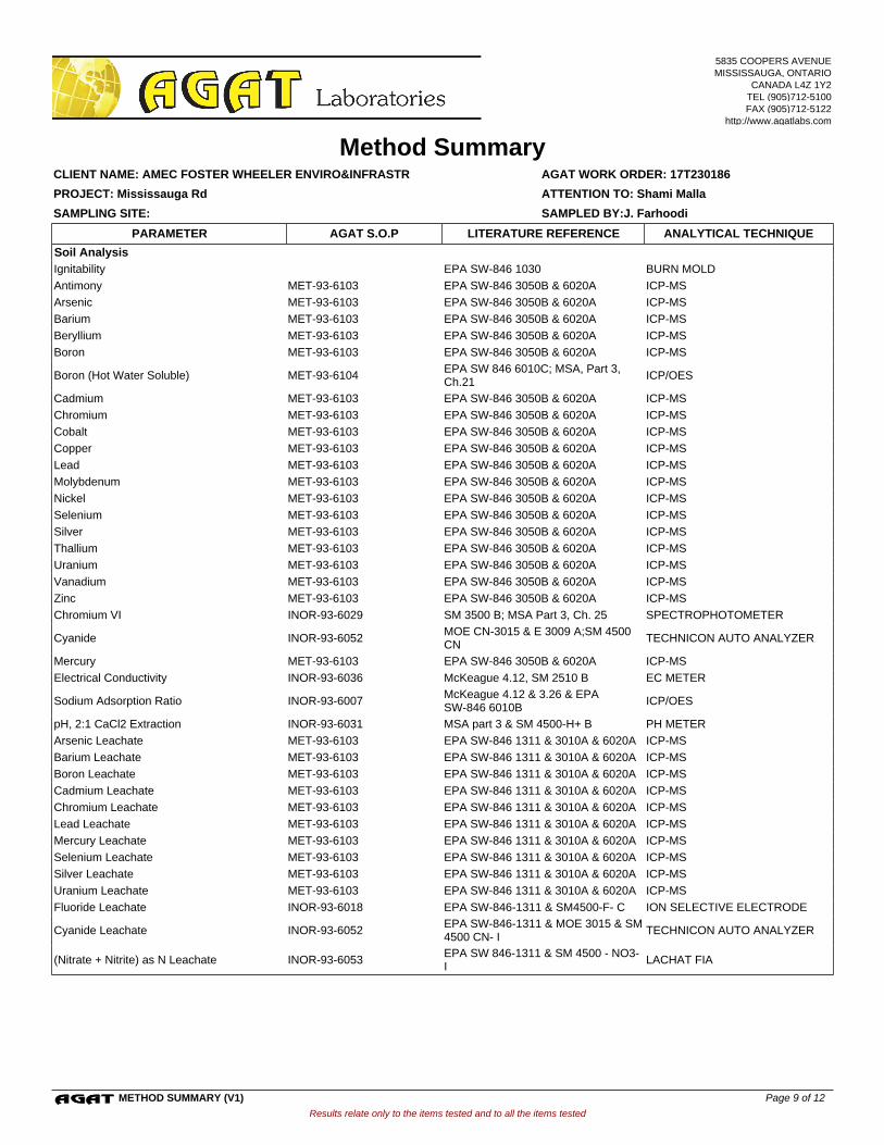
Soil Analysis
Ignitability EPA SW-846 1030 BURN MOLD
Antimony MET-93-6103 EPA SW-846 3050B & 6020A ICP-MS
Arsenic MET-93-6103 EPA SW-846 3050B & 6020A ICP-MS
Barium MET-93-6103 EPA SW-846 3050B & 6020A ICP-MS
Beryllium MET-93-6103 EPA SW-846 3050B & 6020A ICP-MS
Boron MET-93-6103 EPA SW-846 3050B & 6020A ICP-MS
Boron (Hot Water Soluble) MET-93-6104EPA SW 846 6010C; MSA, Part 3, Ch.21
ICP/OES
Cadmium MET-93-6103 EPA SW-846 3050B & 6020A ICP-MS
Chromium MET-93-6103 EPA SW-846 3050B & 6020A ICP-MS
Cobalt MET-93-6103 EPA SW-846 3050B & 6020A ICP-MS
Copper MET-93-6103 EPA SW-846 3050B & 6020A ICP-MS
Lead MET-93-6103 EPA SW-846 3050B & 6020A ICP-MS
Molybdenum MET-93-6103 EPA SW-846 3050B & 6020A ICP-MS
Nickel MET-93-6103 EPA SW-846 3050B & 6020A ICP-MS
Selenium MET-93-6103 EPA SW-846 3050B & 6020A ICP-MS
Silver MET-93-6103 EPA SW-846 3050B & 6020A ICP-MS
Thallium MET-93-6103 EPA SW-846 3050B & 6020A ICP-MS
Uranium MET-93-6103 EPA SW-846 3050B & 6020A ICP-MS
Vanadium MET-93-6103 EPA SW-846 3050B & 6020A ICP-MS
Zinc MET-93-6103 EPA SW-846 3050B & 6020A ICP-MS
Chromium VI INOR-93-6029 SM 3500 B; MSA Part 3, Ch. 25 SPECTROPHOTOMETER
Cyanide INOR-93-6052MOE CN-3015 & E 3009 A;SM 4500 CN
TECHNICON AUTO ANALYZER
Mercury MET-93-6103 EPA SW-846 3050B & 6020A ICP-MS
Electrical Conductivity INOR-93-6036 McKeague 4.12, SM 2510 B EC METER
Sodium Adsorption Ratio INOR-93-6007McKeague 4.12 & 3.26 & EPA SW-846 6010B
ICP/OES
pH, 2:1 CaCl2 Extraction INOR-93-6031 MSA part 3 & SM 4500-H+ B PH METER
Arsenic Leachate MET-93-6103 EPA SW-846 1311 & 3010A & 6020A ICP-MS
Barium Leachate MET-93-6103 EPA SW-846 1311 & 3010A & 6020A ICP-MS
Boron Leachate MET-93-6103 EPA SW-846 1311 & 3010A & 6020A ICP-MS
Cadmium Leachate MET-93-6103 EPA SW-846 1311 & 3010A & 6020A ICP-MS
Chromium Leachate MET-93-6103 EPA SW-846 1311 & 3010A & 6020A ICP-MS
Lead Leachate MET-93-6103 EPA SW-846 1311 & 3010A & 6020A ICP-MS
Mercury Leachate MET-93-6103 EPA SW-846 1311 & 3010A & 6020A ICP-MS
Selenium Leachate MET-93-6103 EPA SW-846 1311 & 3010A & 6020A ICP-MS
Silver Leachate MET-93-6103 EPA SW-846 1311 & 3010A & 6020A ICP-MS
Uranium Leachate MET-93-6103 EPA SW-846 1311 & 3010A & 6020A ICP-MS
Fluoride Leachate INOR-93-6018 EPA SW-846-1311 & SM4500-F- C ION SELECTIVE ELECTRODE
Cyanide Leachate INOR-93-6052EPA SW-846-1311 & MOE 3015 & SM 4500 CN- I
TECHNICON AUTO ANALYZER
(Nitrate + Nitrite) as N Leachate INOR-93-6053EPA SW 846-1311 & SM 4500 - NO3- I
LACHAT FIA
Results relate only to the items tested and to all the items tested
SAMPLING SITE: SAMPLED BY:J. Farhoodi
AGAT WORK ORDER: 17T230186
Method Summary
ATTENTION TO: Shami Malla
CLIENT NAME: AMEC FOSTER WHEELER ENVIRO&INFRASTR
PROJECT: Mississauga Rd
AGAT S.O.P ANALYTICAL TECHNIQUELITERATURE REFERENCEPARAMETER
5835 COOPERS AVENUEMISSISSAUGA, ONTARIO
CANADA L4Z 1Y2TEL (905)712-5100FAX (905)712-5122
http://www.agatlabs.com
METHOD SUMMARY (V1) Page 9 of 12

Trace Organics Analysis
Hexachloroethane ORG-91-5113 EPA SW-846 3541,3620 & 8081 GC/ECD
Gamma-Hexachlorocyclohexane ORG-91-5113 EPA SW-846 3541,3620 & 8081 GC/ECD
Heptachlor ORG-91-5113 EPA SW-846 3541,3620 & 8081 GC/ECD
Aldrin ORG-91-5113 EPA SW-846 3541,3620 & 8081 GC/ECD
Heptachlor Epoxide ORG-91-5113 EPA SW-846 3541,3620 & 8081 GC/ECD
Endosulfan ORG-91-5113 EPA SW-846 3541,3620 & 8081 GC/ECD
Chlordane ORG-91-5113 EPA SW-846 3541,3620 & 8081 GC/ECD
DDE ORG-91-5113 EPA SW-846 3541,3620 & 8081 GC/ECD
DDD ORG-91-5113 EPA SW-846 3541,3620 & 8081 GC/ECD
DDT ORG-91-5113 EPA SW-846 3541,3620 & 8081 GC/ECD
Dieldrin ORG-91-5113 EPA SW-846 3541,3620 & 8081 GC/ECD
Endrin ORG-91-5113 EPA SW-846 3541,3620 & 8081 GC/ECD
Methoxychlor ORG-91-5113 EPA SW-846 3541,3620 & 8081 GC/ECD
Hexachlorobenzene ORG-91-5113 EPA SW-846 3541,3620 & 8081 GC/ECD
Hexachlorobutadiene ORG-91-5113 EPA SW-846 3541,3620 & 8081 GC/ECD
TCMX ORG-91-5112 EPA SW-846 3541,3620 & 8081 GC/ECD
Decachlorobiphenyl ORG-91-5113 EPA SW-846 3541,3620 & 8081 GC/ECD
Moisture Content MOE E3139 BALANCE
F1 (C6 to C10) VOL-91-5009 CCME Tier 1 Method, SW846 5035 P &T GC / FID
F1 (C6 to C10) minus BTEX VOL-91-5009 CCME Tier 1 Method, SW846 5035 P & T GC / FID
F2 (C10 to C16) VOL-91-5009 CCME Tier 1 Method GC / FID
F3 (C16 to C34) VOL-91-5009 CCME Tier 1 Method GC / FID
F4 (C34 to C50) VOL-91-5009 CCME Tier 1 Method GC / FID
Gravimetric Heavy Hydrocarbons VOL-91-5009 CCME Tier 1 Method Balance
Moisture Content VOL-91-5009CCME Tier 1 Method, SW846 5035,8015
BALANCE
Terphenyl VOL-91-5009 CCME Tier 1 Method GC/FID
Dichlorodifluoromethane VOL-91-5002 EPA SW-846 5035 & 8260 (P&T)GC/MS
Vinyl Chloride VOL-91-5002 EPA SW-846 5035 & 8260 (P&T)GC/MS
Bromomethane VOL-91-5002 EPA SW-846 5035 & 8260 (P&T)GC/MS
Trichlorofluoromethane VOL-91-5002 EPA SW-846 5035 & 8260 (P&T)GC/MS
Acetone VOL-91-5002 EPA SW-846 5035 & 8260 (P&T)GC/MS
1,1-Dichloroethylene VOL-91-5002 EPA SW-846 5035 & 8260 (P&T)GC/MS
Methylene Chloride VOL-91-5002 EPA SW-846 5035 & 8260 (P&T)GC/MS
Trans- 1,2-Dichloroethylene VOL-91-5002 EPA SW-846 5035 & 8260 (P&T)GC/MS
Methyl tert-butyl Ether VOL-91-5002 EPA SW-846 5035 & 8260 (P&T)GC/MS
1,1-Dichloroethane VOL-91-5002 EPA SW-846 5035 & 8260 (P&T)GC/MS
Methyl Ethyl Ketone VOL-91-5002 EPA SW-846 5035 & 8260 (P&T)GC/MS
Cis- 1,2-Dichloroethylene VOL-91-5002 EPA SW-846 5035 & 8260 (P&T)GC/MS
Chloroform VOL-91-5002 EPA SW-846 5035 & 8260 (P&T)GC/MS
1,2-Dichloroethane VOL-91-5002 EPA SW-846 5035 & 8260 (P&T)GC/MS
1,1,1-Trichloroethane VOL-91-5002 EPA SW-846 5035 & 8260 (P&T)GC/MS
Carbon Tetrachloride VOL-91-5002 EPA SW-846 5035 & 8260 (P&T)GC/MS
Benzene VOL-91-5002 EPA SW-846 5035 & 8260 (P&T)GC/MS
1,2-Dichloropropane VOL-91-5002 EPA SW-846 5035 & 8260 (P&T)GC/MS
Trichloroethylene VOL-91-5002 EPA SW-846 5035 & 8260 (P&T)GC/MS
Bromodichloromethane VOL-91-5002 EPA SW-846 5035 & 8260 (P&T)GC/MS
Methyl Isobutyl Ketone VOL-91-5002 EPA SW-846 5035 & 8260 (P&T)GC/MS
1,1,2-Trichloroethane VOL-91-5002 EPA SW-846 5035 & 8260 (P&T)GC/MS
Results relate only to the items tested and to all the items tested
SAMPLING SITE: SAMPLED BY:J. Farhoodi
AGAT WORK ORDER: 17T230186
Method Summary
ATTENTION TO: Shami Malla
CLIENT NAME: AMEC FOSTER WHEELER ENVIRO&INFRASTR
PROJECT: Mississauga Rd
AGAT S.O.P ANALYTICAL TECHNIQUELITERATURE REFERENCEPARAMETER
5835 COOPERS AVENUEMISSISSAUGA, ONTARIO
CANADA L4Z 1Y2TEL (905)712-5100FAX (905)712-5122
http://www.agatlabs.com
METHOD SUMMARY (V1) Page 10 of 12

Toluene VOL-91-5002 EPA SW-846 5035 & 8260 (P&T)GC/MS
Dibromochloromethane VOL-91-5002 EPA SW-846 5035 & 8260 (P&T)GC/MS
Ethylene Dibromide VOL-91-5002 EPA SW-846 5035 & 8260 (P&T)GC/MS
Tetrachloroethylene VOL-91-5002 EPA SW-846 5035 & 8260 (P&T)GC/MS
1,1,1,2-Tetrachloroethane VOL-91-5002 EPA SW-846 5035 & 8260 (P&T)GC/MS
Chlorobenzene VOL-91-5002 EPA SW-846 5035 & 8260 (P&T)GC/MS
Ethylbenzene VOL-91-5002 EPA SW-846 5035 & 8260 (P&T)GC/MS
m & p-Xylene VOL-91-5002 EPA SW-846 5035 & 8260 (P&T)GC/MS
Bromoform VOL-91-5002 EPA SW-846 5035 & 8260 (P&T)GC/MS
Styrene VOL-91-5002 EPA SW-846 5035 & 8260 (P&T)GC/MS
1,1,2,2-Tetrachloroethane VOL-91-5002 EPA SW-846 5035 & 8260 (P&T)GC/MS
o-Xylene VOL-91-5002 EPA SW-846 5035 & 8260 (P&T)GC/MS
1,3-Dichlorobenzene VOL-91-5002 EPA SW-846 5035 & 8260 (P&T)GC/MS
1,4-Dichlorobenzene VOL-91-5002 EPA SW-846 5035 & 8260 (P&T)GC/MS
1,2-Dichlorobenzene VOL-91-5002 EPA SW-846 5035 & 8260 (P&T)GC/MS
Xylene Mixture VOL-91-5002 EPA SW-846 5035 & 8260 (P&T)GC/MS
1,3-Dichloropropene VOL-91-5002 EPA SW-846 5035 & 8260 (P&T)GC/MS
n-Hexane VOL-91-5002 EPA SW-846 5035 & 8260 (P&T)GC/MS
Toluene-d8 VOL-91-5002 EPA SW-846 5035 & 8260 (P&T)GC/MS
4-Bromofluorobenzene VOL-91-5002 EPA SW-846 5035 & 8260 (P&T)GC/MS
Vinyl Chloride VOL-91-5001 EPA SW-846 5230B & 8260 (P&T)GC/MS
1,1 Dichloroethene VOL-91-5001 EPA SW-846 5230B & 8260 (P&T)GC/MS
Dichloromethane VOL-91-5001 EPA SW-846 5230B & 8260 (P&T)GC/MS
Methyl Ethyl Ketone VOL-91-5001 EPA SW-846 5230B & 8260 (P&T)GC/MS
Chloroform VOL-91-5001 EPA SW-846 5230B & 8260 (P&T)GC/MS
1,2-Dichloroethane VOL-91-5001 EPA SW-846 5230B & 8260 (P&T)GC/MS
Carbon Tetrachloride VOL-91-5001 EPA SW-846 5230B & 8260 (P&T)GC/MS
Benzene VOL-91-5001 EPA SW-846 5230B & 8260 (P&T)GC/MS
Trichloroethene VOL-91-5001 EPA SW-846 5230B & 8260 (P&T)GC/MS
Tetrachloroethene VOL-91-5001 EPA SW-846 5230B & 8260 (P&T)GC/MS
Chlorobenzene VOL-91-5001 EPA SW-846 5230B & 8260 (P&T)GC/MS
1,2-Dichlorobenzene VOL-91-5001 EPA SW-846 5230B & 8260 (P&T)GC/MS
1,4-Dichlorobenzene VOL-91-5001 EPA SW-846 5230B & 8260 (P&T)GC/MS
Toluene-d8 VOL-91-5001 EPA SW-846 5230B & 8260 (P&T)GC/MS
Results relate only to the items tested and to all the items tested
SAMPLING SITE: SAMPLED BY:J. Farhoodi
AGAT WORK ORDER: 17T230186
Method Summary
ATTENTION TO: Shami Malla
CLIENT NAME: AMEC FOSTER WHEELER ENVIRO&INFRASTR
PROJECT: Mississauga Rd
AGAT S.O.P ANALYTICAL TECHNIQUELITERATURE REFERENCEPARAMETER
5835 COOPERS AVENUEMISSISSAUGA, ONTARIO
CANADA L4Z 1Y2TEL (905)712-5100FAX (905)712-5122
http://www.agatlabs.com
METHOD SUMMARY (V1) Page 11 of 12

Page 12 of 12