geotechnical investigation shady oak valley …...geotechnical investigation shady oak 27522 valley...
TRANSCRIPT
GEOTECHNICAL INVESTIGATION
SHADY OAK27522 VALLEY CENTER ROAD
VALLEY CENTER, CALIFORNIA
PREPARED FOR
TOUCHSTONE COMMUNITIES9909 MIRA MESA BOULEVARD, SUITE #150
SAN DIEGO, CALIFORNIA 92131
PREPARED BY
CHRISTIAN WHEELER ENGINEERING3980 HOME AVENUE
SAN DIEGO, CALIFORNIA 92105
CHRISTIAN WHEELERE N G I N E E R I N G
3 9 8 0 H o m e A v e n u e S a n D i e g o , C A 9 2 1 0 5 6 1 9 - 5 5 0 - 1 7 0 0 F A X 6 1 9 - 5 5 0 - 1 7 0 1
August 5, 2016
Touchstone Communities CWE 2150438.01
9909 Mira Mesa Boulevard, Suite #150
San Diego, California 92131
Attention: Brian Nestoroff
Subject: Geotechnical Investigation, Shady Oak27522 Valley Center Road, Valley Center, California
In accordance with your request and our proposal dated July 24, 2015, we have completed a preliminary
geotechnical investigation for the subject project. We are presenting herein our findings and
recommendations.
In general, we found the subject property suitable for the proposed construction, provided the
recommendations provided herein are followed. Compressible surficial soils, including residual soils and
previous fills, will need to be removed and replaced as properly compacted fill during the site grading.
Specific remedial grading recommendations and geotechnical design criteria are presented in the attached
report.
If you have any questions after reviewing this report, please do not hesitate to contact our office. This
opportunity to be of professional service is sincerely appreciated.
Respectfully submitted,
CHRISTIAN WHEELER ENGINEERING
_____________________________ _______________________________
Shawn Caya, R.G.E. #2748 Troy S. Wilson, C.E.G. #2551
SCC:scc;tsw
Distribution: [email protected]
CHRISTIAN WHEELERE N G I N E E R I N G
3 9 8 0 H o m e A v e n u e S a n D i e g o , C A 9 2 1 0 5 6 1 9 - 5 5 0 - 1 7 0 0 F A X 6 1 9 - 5 5 0 - 1 7 0 1
CWE 2150438.01Shady Oak
27522 Valley Center Road, Valley Center, California
TABLE OF CONTENTS
PAGE
Introduction and Project Description ............................................................................................................................. 1Investigation Scope............................................................................................................................................................. 2Findings ................................................................................................................................................................................ 3
Site Description .............................................................................................................................................................. 3General Geology and Subsurface Conditions............................................................................................................ 3
Geologic Setting and Soil Description ................................................................................................................... 3Artificial Fill ........................................................................................................................................................... 3Residual Soil ........................................................................................................................................................... 3Weathered Granitics ............................................................................................................................................. 4
Groundwater .............................................................................................................................................................. 4Tectonic Setting ......................................................................................................................................................... 4
Geologic Hazards........................................................................................................................................................... 5Landslide Potential and Slope Stability .................................................................................................................. 5Liquefaction................................................................................................................................................................ 6Flooding ...................................................................................................................................................................... 6Tsunamis ..................................................................................................................................................................... 6Seiches ......................................................................................................................................................................... 6
Conclusions.......................................................................................................................................................................... 6Recommendations .............................................................................................................................................................. 7
Grading and Earthwork ................................................................................................................................................ 7General ........................................................................................................................................................................ 7Observation of Grading ........................................................................................................................................... 7Clearing and Grubbing ............................................................................................................................................. 7Test Trench Backfill .................................................................................................................................................. 8Processing of Removal Bottom .............................................................................................................................. 8Compaction and Method of Filling ........................................................................................................................ 8Fill Slope Construction............................................................................................................................................. 8Imported Fill Material............................................................................................................................................... 9Temporary Cut Slopes .............................................................................................................................................. 9Surface Drainage........................................................................................................................................................ 9Grading Plan Review ................................................................................................................................................ 9
Conventional Shallow Foundations .......................................................................................................................... 10General ...................................................................................................................................................................... 10Minimum Dimensions ............................................................................................................................................ 10Bearing Capacity ...................................................................................................................................................... 10Footing Reinforcing ................................................................................................................................................ 10Lateral Load Resistance .......................................................................................................................................... 10Settlement Characteristics ...................................................................................................................................... 10
Post-Tensioned Foundations....................................................................................................................................... 11Foundation Plan Review ............................................................................................................................................. 11Foundation Excavation Observation........................................................................................................................ 11Soluble Sufates .............................................................................................................................................................. 12On-Grade Slabs ............................................................................................................................................................ 12
General ...................................................................................................................................................................... 12Interior Slab.............................................................................................................................................................. 12Under-Slab Vapor Retarders.................................................................................................................................. 12
Earth Retaining Walls .................................................................................................................................................. 13Foundations.............................................................................................................................................................. 13
CWE 2150438.01Shady Oak
27522 Valley Center Road, Valley Center, California
TABLE OF CONTENTS (Continued)
PAGE
Active Pressures....................................................................................................................................................... 13Waterproofing and Subdrains................................................................................................................................ 14Backfill....................................................................................................................................................................... 14
Preliminary Pavement Sections.................................................................................................................................. 14General ...................................................................................................................................................................... 14Asphalt Concrete ..................................................................................................................................................... 14Concrete Pavements................................................................................................................................................ 15
Limitations ......................................................................................................................................................................... 16Review, Observation and Testing.............................................................................................................................. 16Uniformity of Conditions ........................................................................................................................................... 16Change in Scope ........................................................................................................................................................... 17Time Limitations .......................................................................................................................................................... 17Professional Standard .................................................................................................................................................. 17Client's Responsibility.................................................................................................................................................. 18
Field Explorations ............................................................................................................................................................ 18Laboratory Testing ........................................................................................................................................................... 18
TABLESTable I: Proximal Fault Zones .......................................................................................................................................... 5Table II: CBC 2013 Edition – Seismic Design Parameters.......................................................................................... 6Table III: Post-Tension Design Criteria........................................................................................................................ 11Table IV: Asphalt Concrete and Paver Sections.......................................................................................................... 15Table V: Concrete Pavement Design Parameters........................................................................................................ 15Table VI: Minimum Concrete Pavement Thickness................................................................................................... 16
FIGURESFigure 1 Site Vicinity Map, Follows Page 1
PLATESPlate 1 Site Plan and Geotechnical MapPlate 2 Retaining Wall Subdrain Detail
APPENDICESAppendix A Trench LogsAppendix B Laboratory Test ResultsAppendix C ReferencesAppendix D Recommended Grading Specifications – General Provisions
GEOTECHNICAL INVESTIGATION
SHADY OAK
27522 VALLEY CENTER ROADVALLEY CENTER, CALIFORNIA
INTRODUCTION AND PROJECT DESCRIPTION
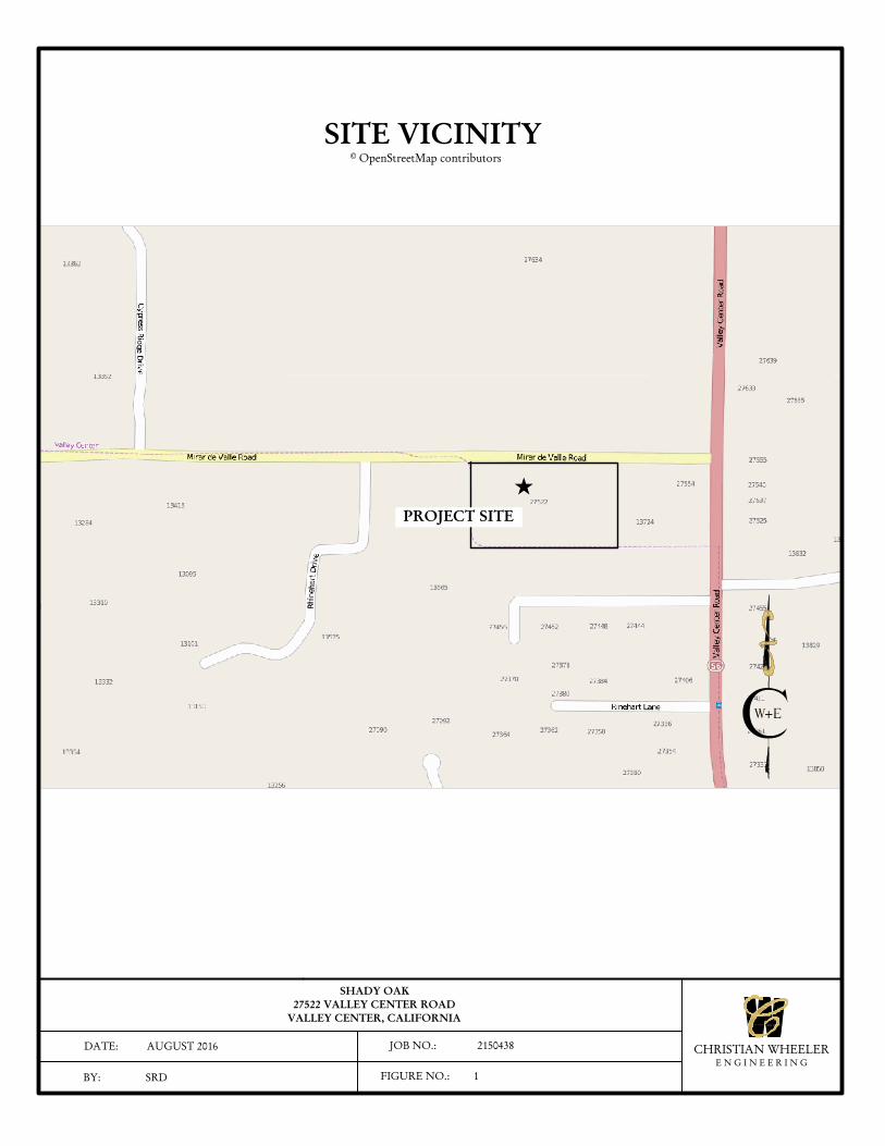
This report presents the results of a geotechnical investigation performed for a 47-Lot subdivision to be
constructed within a mostly vacant lot at 27522 Valley Center Road, in the Valley Center area of the County
of San Diego, California. The following Figure Number 1 presents a vicinity map showing the location of the
project.
We understand that it is proposed to construct a residential subdivision on the property. The subdivision will
include 47 single-family homes and associated streets and utility improvements. We expect that the homes
will be one- and/or two-story, wood-frame structures with concrete on-grade floor slabs. Grading will consist
of cuts and fills of less than about five feet from the existing site grades with site retaining walls of similar
heights. Biofiltration basins are planned along the northern boundary of the site.
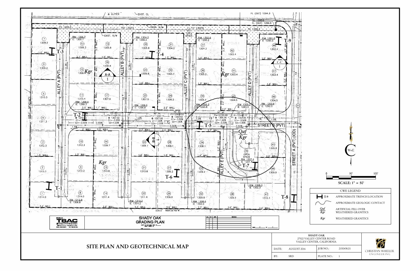
To assist in the preparation of this report, our firm has been given a Grading Plan prepared by TSAC
Engineering (undated). This plan has been used as the base for our Site Plan and Geotechnical Map, which is
included herewith as Plate Number 1.
This report has been prepared for the exclusive use of Touchstone Communities and its consultants for
specific application to the project described herein. Should the project be modified, the new plans should be
submitted to Christian Wheeler Engineering for review to determine whether the findings and
recommendations presented herein remain applicable and if any additional subsurface investigation,
laboratory testing and/or recommendations are necessary. Our professional services have been performed,
our findings obtained, and our recommendations prepared in accordance with generally accepted engineering
principles and practices. This warranty is in lieu of all other warranties, expressed or implied.
CHRISTIAN WHEELERE N G I N E E R I N G
3 9 8 0 H o m e A v e n u e S a n D i e g o , C A 9 2 1 0 5 6 1 9 - 5 5 0 - 1 7 0 0 F A X 6 1 9 - 5 5 0 - 1 7 0 1
SHADY OAK27522 VALLEY CENTER ROAD
VALLEY CENTER, CALIFORNIA
DATE: AUGUST 2016
BY: SRD
JOB NO.: 2150438
FIGURE NO.: 1
CHRISTIAN WHEELERE N G I N E E R I N G
SITE VICINITY© OpenStreetMap contributors
PROJECT SITE
CWE 2150438.01 August 5, 2016 Page 2
INVESTIGATION SCOPE
Our preliminary geotechnical investigation consisted of surface reconnaissance, subsurface exploration,
obtaining representative soil samples, laboratory testing, analysis of the field and laboratory data and review
of relevant geologic literature. Our scope of service did not include assessment of hazardous substance
contamination, recommendations to prevent floor slab moisture intrusion or the formation of mold within
the structure, or any other services not specifically described in the scope of services presented below. More
specifically, our intent was to provide the services listed below.
Excavate nine backhoe trenches on the site to explore the existing soil conditions.
Backfill the trenches with the removed soil. It should be noted that the soil was not compacted and
will have to be removed and replaced as compacted fill during site grading.
Evaluate, by laboratory tests and our past experience with similar soil types, the engineering
properties of the various soil strata that may influence the proposed construction, including bearing
capacities, expansive characteristics and settlement potential.
Describe the general geology at the site, including possible geologic hazards that could have an effect
on the proposed construction, and provide the seismic design parameters as required by the 2013
edition of the California Building Code.
Address potential construction difficulties that may be encountered due to soil conditions,
groundwater or geologic hazards, and provide geotechnical recommendations to deal with these
difficulties.
Provide site preparation and grading recommendations for the anticipated work.
Provide foundation recommendations for the type of construction anticipated and develop soil
engineering design criteria for the recommended foundation designs.
Provide design parameters for unrestrained retaining walls.
Provide preliminary pavement section recommendations.
Prepare this report, which includes, in addition to our conclusions and recommendations, a plot plan
showing the areal extent of the geological units and the locations of our exploratory borings,
exploration logs, and a summary of the laboratory test results.
Although a test for the presence of soluble sulfates within the soils that may be in contact with reinforced
concrete was performed as part of the scope of our services, it should be understood Christian Wheeler
Engineering does not practice corrosion engineering. If such an analysis is considered necessary, we
recommend that the client retain an engineering firm that specializes in this field to consult with them on this
CWE 2150438.01 August 5, 2016 Page 3
matter. The results of these tests should only be used as a guideline to determine if additional testing and
analysis is necessary.
FINDINGS
SITE DESCRIPTION
The subject site is a 4.56 acre, rectangular-shaped lot identified as Assessor’s Parcel Number 186-270-01.The lot is
located just west of the intersection of Valley Center Road and Mirar de Valle and is bordered by Mirar de Valle
to the north and by vacant land on the remaining sides. The property supports an existing residence and
associated improvements in the southeastern portion and is undeveloped in the remaining portions. It appears
that portions of the property have been used as a dump site as there are several small stockpiles of dirt, concrete,
and other debris. Topographically, the site slopes gently to the north-northeast with elevations ranging from
about 1296 feet (datum unknown) in the northeast corner to 1315 feet in the southwest corner.
GENERAL GEOLOGY AND SUBSURFACE CONDITIONS
GEOLOGIC SETTING AND SOIL DESCRIPTION: The subject site is located in the Foothills
Physiographic Province of San Diego County. Based upon the results of our subsurface exploration and analysis
of readily available, pertinent geologic literature, it was determined that the project area is underlain by
Cretaceous-age granitic bedrock, residual soil, and artificial fill. These materials are described below.
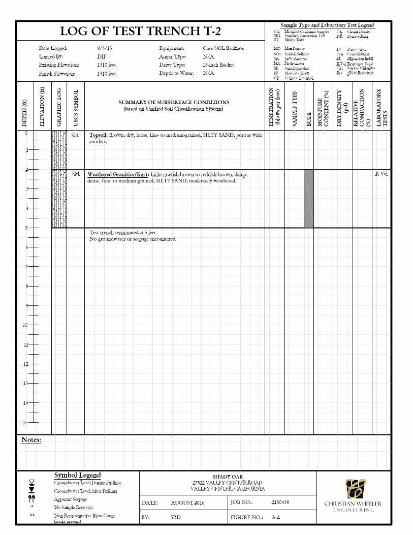
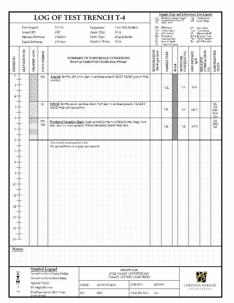
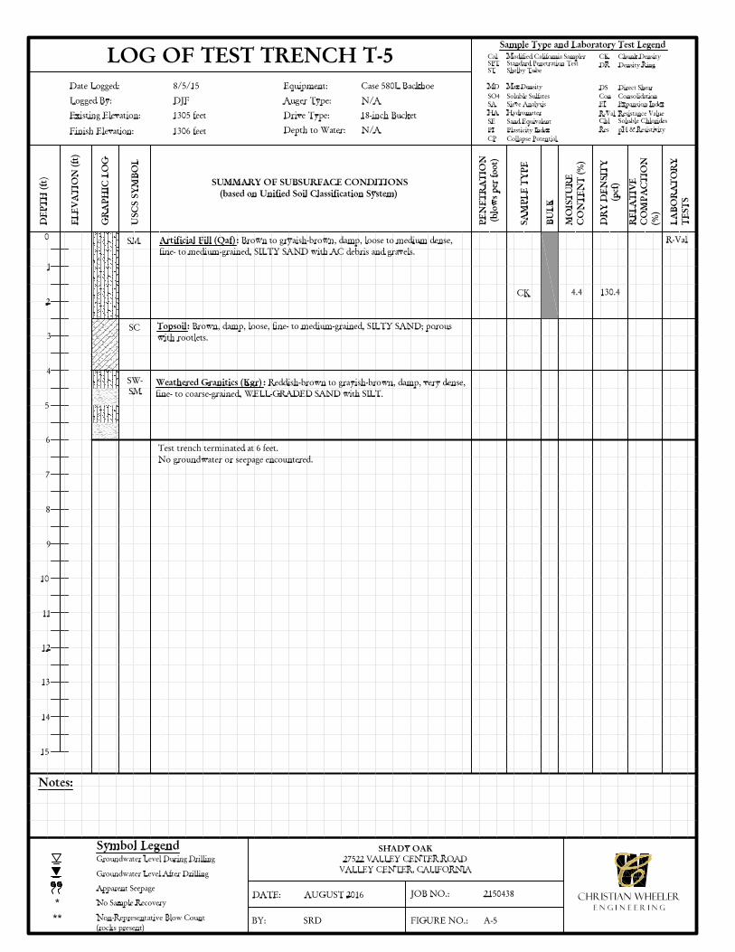
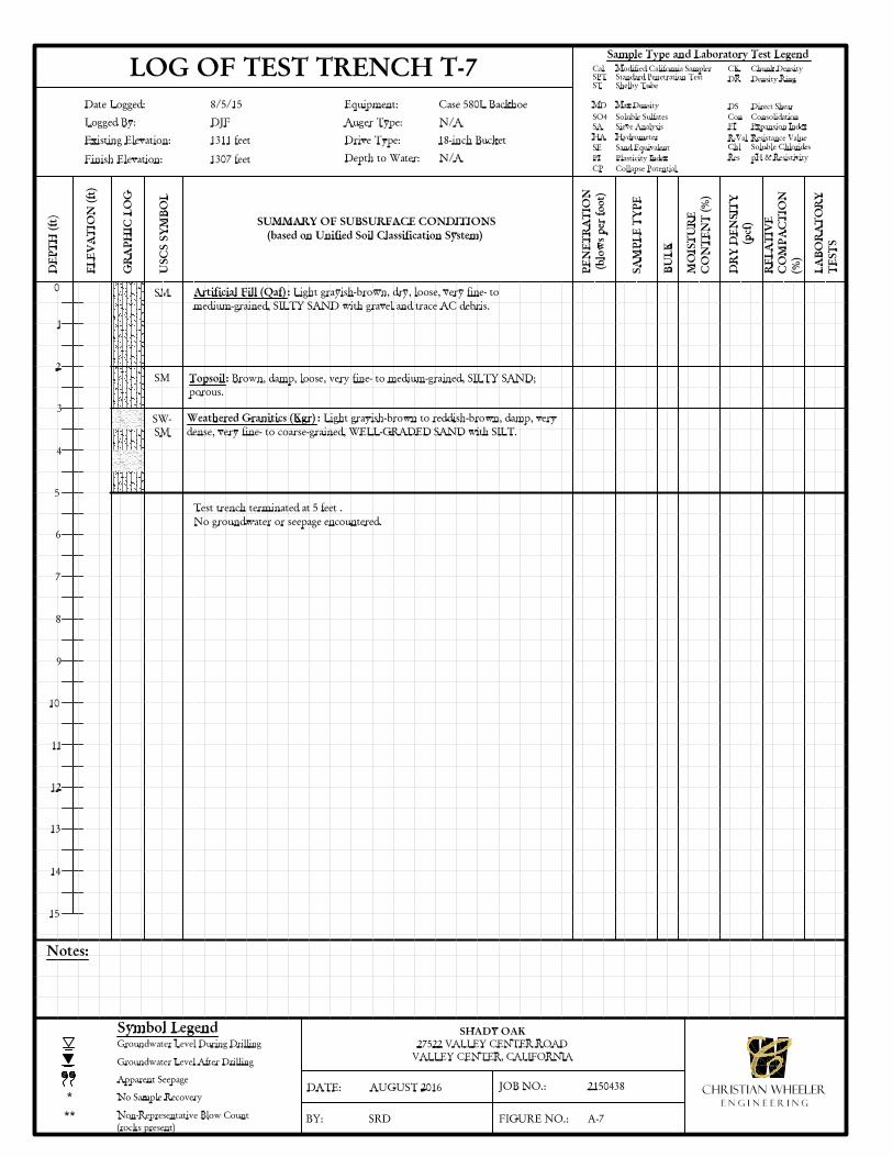
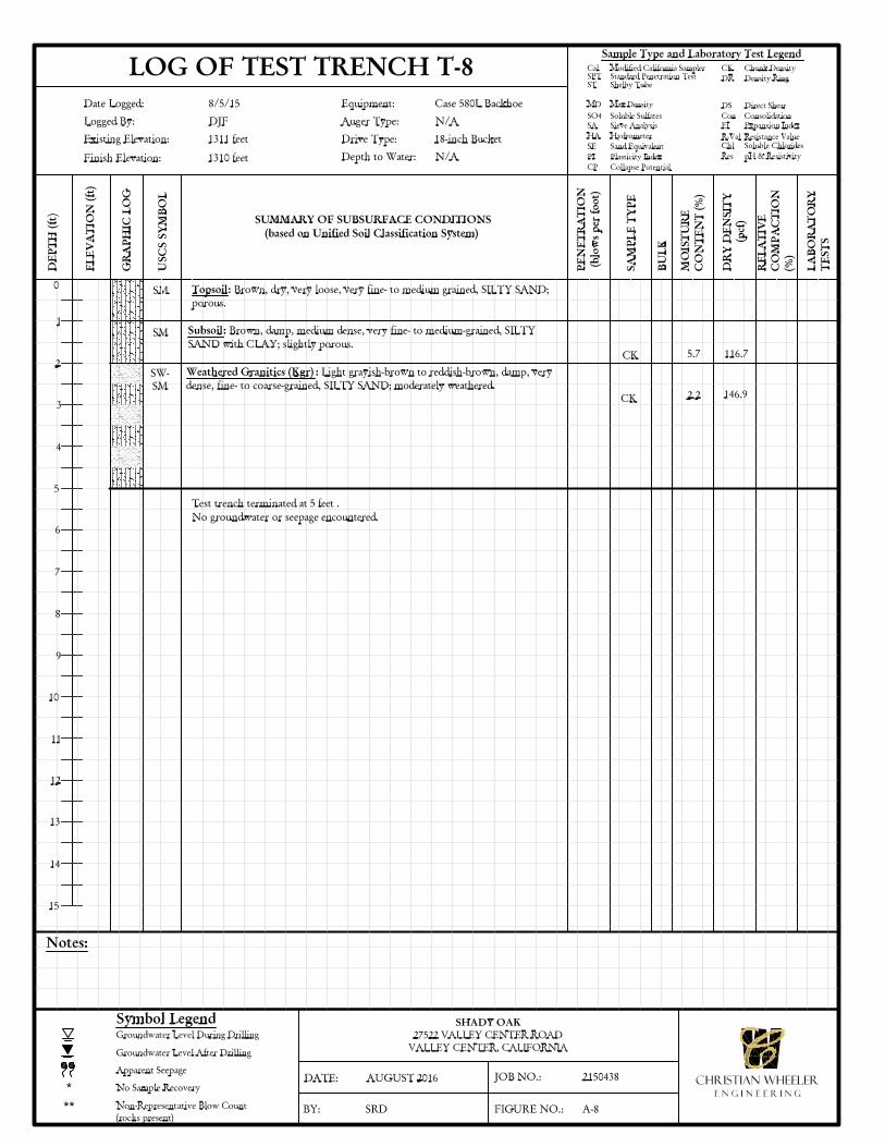
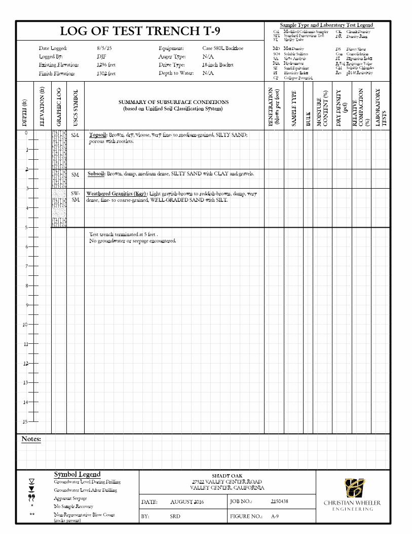
ARTIFICIAL FILL (Qaf): Artificial fill was encountered in areas that support the existing
development in the southeast portion of the property. As encountered in trenches T-5 and T-7, the
fill soils extended to a depth of about 2 to 2½ feet below existing site grade and generally consisted
of brown to grayish-brown, dry to damp, loose to medium dense, silty sand (SM) with some gravel.
The fill materials were judged to have a very low expansion index (EI<20).
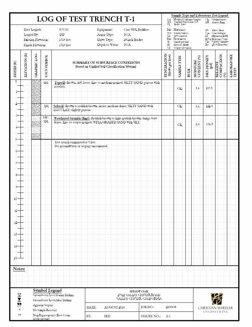
RESIDUAL SOIL: A layer of residual soil consisting of natural topsoil and/or subsoil was
encountered in each of our exploratory trenches. The topsoil layer, which was encountered in all the
trenches, extended to depths ranging from about 1 foot to 4 feet below existing grade. The topsoil
consists of brown, dry to damp, loose, porous, silty sand (SM) that is judged to have a very low
expansion index (EI<20). A layer of subsoil was encountered underlying the topsoil in 6 of our 9
exploratory trenches. Where encountered, the subsoil layer ranged from about 1 foot to 1½ feet in
thickness and extended to approximately 2 to 4 feet below the existing grade. The subsoil consists
CWE 2150438.01 August 5, 2016 Page 4
of reddish-brown, damp to moist, medium dense, clayey sand (SC) that was found to have a low
expansion index (EI=35).
WEATHERED GRANITICS (Kgr): Weathered granitic bedrock underlies the surficial soils.
Within our trenches, the weathered granitics were encountered at depths ranging from about 2 to 4
feet below the existing grades. This material consists of reddish-brown and light gray, damp, dense
to very dense, silty sand (SM) and well-graded sand with silt (SW-SM). These deposits were judged
to have a very low expansion index (EI<20).
GROUNDWATER: No groundwater or wet soil was encountered in any of our subsurface explorations. It
should be recognized that minor groundwater seepage problems might occur after development of a site even
where none were present before development. These are usually minor phenomena and are often the result of an
alteration in drainage patterns and/or an increase in irrigation water. Based on the permeability characteristics of
the soil and the anticipated usage and development, it is our opinion that any seepage problems which may occur
will be minor in extent. It is further our opinion that these problems can be most effectively corrected on an
individual basis if and when they occur.
TECTONIC SETTING: No active or potentially active faults are known to traverse the subject site.
However, it should be noted that much of Southern California, including the San Diego County area, is
characterized by a series of Quaternary-age fault zones that consist of several individual, en echelon faults that
generally strike in a northerly to northwesterly direction. Some of these fault zones (and the individual faults
within the zone) are classified as “active” according to the criteria of the California Division of Mines and
Geology. Active fault zones are those that have shown conclusive evidence of faulting during the Holocene
Epoch (the most recent 11,000 years). The Division of Mines and Geology used the term “potentially active”
on Earthquake Fault Zone maps until 1988 to refer to all Quaternary-age (last 1.6 million years) faults for the
purpose of evaluation for possible zonation in accordance with the Alquist-Priolo Earthquake Fault Zoning
Act and identified all Quaternary-age faults as “potentially active” except for certain faults that were
presumed to be inactive based on direct geologic evidence of inactivity during all of Holocene time or longer.
Some faults considered to be “potentially active” would be considered to be “active” but lack specific criteria
used by the State Geologist, such as sufficiently active and well-defined. Faults older than Quaternary-age are not
specifically defined in Special Publication 42, Fault Rupture Hazard Zones in California, published by the
California Division of Mines and Geology. However, it is generally accepted that faults showing no
movement during the Quaternary period may be considered to be “inactive”.
CWE 2150438.01 August 5, 2016 Page 5
A review of available geologic maps indicates that the nearest active fault zone is the Elsinore Fault Zone
(Julian portion), located approximately 15 kilometers northeast of the site. Other active fault zones in the
region that could possibly affect the site include the Rose Canyon, Newport-Inglewood and Coronado Bank
Fault Zone to the west; Palos Verdes Fault Zones to the northwest; and the Earthquake Valley and San
Andreas Fault Zones to the east.
TABLE I: PROXIMAL FAULT ZONESFault Zone Distance
Elsinore (Julian) 15 kmRose Canyon 35 kmNewport-Inglewood 37 kmEarthquake Valley 42 kmCoronado Bank 58 kmPalos Verdes 84 km
GEOLOGIC HAZARDS
LANDSLIDE POTENTIAL AND SLOPE STABILITY: As part of this investigation we reviewed the
publication, “Landslide Hazards in the Northern Part of the San Diego Metropolitan Area” by Tan, 1995. This
reference is a comprehensive study that classifies San Diego County into areas of relative landslide susceptibility.
According to this publication, the site is located in Relative Landslide Susceptibility Area 2. Area 2 is considered
to be “marginally susceptible” to landsliding. Based on our findings, it is our professional opinion that the
potential for slope failures within the site is very low.
SEISMIC HAZARD: A likely geologic hazard to affect the site is ground shaking as a result of movement
along one of the major active fault zones mentioned in the “Tectonic Setting” section of this report. Per Chapter
16 of the 2013 California Building Code (CBC), the Risk-Targeted Maximum Considered Earthquake (MCER)
ground acceleration is that which results in the largest maximum response to horizontal ground motions with
adjustments for a targeted risk of structural collapse equal to one percent in 50 years. Figures 1613.3.1(1) and
1613.3.1(2) of the CBC present MCER accelerations for short (0.2 sec.) and long (1.0 sec.) periods, respectively,
based on a soil Site Class B (CBC 1613.3.2) and a structural damping of five percent. For the subject site,
correlation with the known properties of the underlying bedrock indicates that the upper 100 feet of geologic
subgrade can be characterized as Site Class C. In this case, the mapped MCER accelerations are modified using
the Site Coefficients presented in Tables 1613.3.3(1) and (2). The modified MCE spectral accelerations are then
multiplied by two-thirds in order to obtain the design spectral accelerations. These seismic design parameters for
the subject site (33.2105°, -117.0364°), based on Chapter 16 of the CBC, are presented in Table II below.

CWE 2150438.01 August 5, 2016 Page 6
TABLE II: CBC 2013 EDITION – SEISMIC DESIGN PARAMETERS
CBC – Chapter 16 Section Seismic Design Parameter Recommended ValueSection 1613.3.2 Soil Site Class C
Figure 1613.3.1 (1) MCER Acceleration for Short Periods (0.2 sec), Ss 1.205 gFigure 1613.3.1 (2) MCER Acceleration for 1.0 Sec Periods (1.0 sec), S1 0.460 gTable 1613.3.3 (1) Site Coefficient, Fa 1.000Table 1613.3.3 (2) Site Coefficient, Fv 1.340Section 1613.3.3 SMS = MCER Spectral Response at 0.2 sec. = (Ss)(Fa) 1.204 gSection 1613.3.3 SM1 = MCER Spectral Response at 1.0 sec. = (S1)(Fv) 0.617 gSection 1613.3.4 SDS = Design Spectral Response at 0.2 sec. = 2/3(SMS) 0.804 gSection 1613.3.4 SD1 = Design Spectral Response at 1.0 sec. = 2/3(SM1) 0.411 gSection 1803.2.12 PGAM per Section 11.8.3 of ASCE 7 0.46 g
LIQUEFACTION: The near-surface soils encountered at the site are not considered susceptible to liquefaction
due to such factors as depth to the groundwater table, soil density and grain-size distribution.
FLOODING: The site is not located flood hazard area according to the maps prepared by the Federal
Emergency Management Agency.
TSUNAMIS: Tsunamis are great sea waves produced by submarine earthquakes or volcanic eruptions.
According to the San Diego County Multi-Jurisdictional Hazard Mitigation Plan, the project site is located outside
the limits of the maximum projected tsunami runup.
SEICHES: Seiches are periodic oscillations in large bodies of water such as lakes, harbors, bays or reservoirs.
Due to the site’s location, it should not be affected by seiches.
CONCLUSIONS
Based on our investigation, it is our opinion that the subject property is suitable for the proposed subdivision
provided the geotechnical recommendations presented in this report are followed. The main geotechnical
condition affecting the proposed development is the presence of potentially compressible, near-surface soils
comprised of artificial fill and residual soil. These materials will need to be overexcavated and recompacted in
order to support the proposed improvements. Additionally, stockpiled debris will need to be removed from
the site prior to grading.
The site is located in an area that is relatively free of geologic hazards that will have a significant effect on the
proposed development. The most likely geologic hazard that could affect the site is ground shaking due to
CWE 2150438.01 August 5, 2016 Page 7
seismic activity along one of the regional active faults. However, construction in accordance with the
requirements of the most recent edition of the California Building Code and the local governmental agencies
should provide a level of life-safety suitable for the type of development proposed.
RECOMMENDATIONS
GRADING AND EARTHWORK
GENERAL: All grading should conform to the guidelines presented in Appendix J of the California Building
Code, the minimum requirements of the County of San Diego, and the recommended Grading Specifications
and Special Provisions attached hereto, except where specifically superseded in the text of this report. Prior to
grading, a representative of Christian Wheeler Engineering should be present at the pre-construction meeting to
provide additional grading guidelines, if necessary, and to review the earthwork schedule.
OBSERVATION OF GRADING: Continuous observation by the Geotechnical Consultant is essential
during the grading operation to confirm conditions anticipated by our investigation, to allow adjustments in
design criteria to reflect actual field conditions exposed, and to determine that the grading proceeds in general
accordance with the recommendations contained herein.
CLEARING AND GRUBBING: Site preparation should begin with demolition and removal of the existing
improvements and the stripping and removal of vegetation, construction debris and other deleterious materials
from the site. This should include all significant root material and any debris from the on-site stockpiles. The
resulting materials should be disposed of off-site in a legal dumpsite.
SITE PREPARATION: Where it is not removed by the planned grading, the upper 4 feet of existing soil
should be removed. We anticipate that such removals will expose competent weathered granitics at the base
of the excavation. Deeper removals may be necessary in areas of the site not investigated or in areas where
loose, dry, or otherwise unacceptable soils are exposed. The removals can be limited to 3 feet below the
existing grade where granitic rock is exposed at the base of the removal. Laterally, the removals should extend
to the property line or 5 feet outside areas to support fill and/or settlement-sensitive improvements,
whichever is less. No removals are recommended beyond property lines except along the eastern boundary
where permission for off-site grading has been granted. All excavated areas should be approved by the
geotechnical engineer or his representative prior to replacing any of the excavated soils. The excavated
material can be replaced as properly compacted fill provided that it is free of deleterious debris. Fill soils
CWE 2150438.01 August 5, 2016 Page 8
should be compacted in accordance with the recommendations presented in the “Compaction and Method of
Filling” section of this report.
TEST TRENCH BACKFILL: Backfill associated with our subsurface explorations underlying settlement-
sensitive improvements not removed as part of site preparation operations should be removed and replaced
as compacted fill.
PROCESSING OF REMOVAL BOTTOM: Prior to placing any new fill soils or constructing any new
improvements in areas that have been overexcavated as recommended in the “Site Preparation” section of this
report, the exposed soils should be scarified to a depth of 12 inches, moisture conditioned, and compacted to at
least 90 percent relative compaction. In areas to support fill slopes, keys should be cut into the competent
supporting materials such as the weathered granitics. The keys should be at least twelve feet wide and be sloped
back at least two percent. The keys should extend at least one foot into the competent supporting materials.
Where the existing ground has a slope of 5:1 (horizontal to vertical) or steeper, it should be benched into as the
fill extends upward from the keyways. The benching should remove all loose surficial soils and should create level
areas on which to place the fill material.
COMPACTION AND METHOD OF FILLING: All structural fill and backfill material placed at the site,
except as noted below, should be compacted to a relative compaction of at least 90 percent of maximum dry
density as determined by ASTM Laboratory Test D1557. Fills should be placed at or slightly above optimum
moisture content, in lifts six to eight inches thick, with each lift compacted by mechanical means. Fills should
consist of approved earth material, free of trash or debris, roots, vegetation, or other materials determined to be
unsuitable by our soil technicians or project geologist. Fill material should be free of rocks or lumps of soil in
excess of twelve inches in maximum dimension; however, this should be reduced to six inches within four feet of
finish grade.
All utility trench backfill should be compacted to a minimum of 90 percent of its maximum dry density. The
upper twelve inches of subgrade beneath paved areas should be compacted to 95 percent of the materials
maximum dry density. This compaction should be obtained by the paving contractor just prior to placing the
aggregate base material and should not be part of the mass grading requirements or operation.
FILL SLOPE CONSTRUCTION: Fill slopes may be constructed at an inclination of 2:1 or flatter
(horizontal to vertical). Compaction of slopes should be performed by back-rolling with a sheepsfoot
compactor at vertical intervals of four feet or less as the fill is being placed, and track-walking the face of the
slope when the slope is completed. As an alternative, the fill slopes may be overfilled by at least three feet and

CWE 2150438.01 August 5, 2016 Page 9
then cut back to the compacted core at the design line and grade. Keys should be made at the toe of fill slopes
in accordance with the recommendations presented above under "Processing of Removal Bottom."
IMPORTED FILL MATERIAL: Soils to be imported to the site should be evaluated and approved by the
Geotechnical Consultant prior to being imported. At least five working days-notice of a potential import source
should be given to the Geotechnical Consultant so that appropriate testing can be accomplished. The type of
material considered most desirable for import is granular material containing some silt or clay binder, which has
an Expansion Index of less than 50. Less than 25 percent of the material should be larger than the Standard #4
sieve, and less than 25 percent finer than the Standard # 200 sieve. Soils not meeting there criteria should not be
used for structural fill or backfill.
TEMPORARY CUT SLOPES: The contractor is solely responsible for designing and constructing stable,
temporary excavations and will need to shore, slope, or bench the sides of trench excavations as required to
maintain the stability of the excavation sides. The contractor’s “competent person”, as defined in the OSHA
Construction Standards for Excavations, 29 CFR, Part 1926, should evaluate the soil exposed in the excavations
as part of the contractor’s safety process. We anticipate that the existing on-site soils will consist of Type C
material. Our firm should be contacted to observe all temporary cut slopes during grading to ascertain that no
unforeseen adverse conditions exist. No surcharge loads such as foundation loads, or soil or equipment
stockpiles, vehicles, etc. should be allowed within a distance from the top of temporary slopes equal to half the
slope height.
SURFACE DRAINAGE: The ground around the proposed structures should be graded so that surface water
flows rapidly away from the structures without ponding. In general, we recommend that the ground adjacent to
structure slope away at a gradient of at least two percent. Densely vegetated areas where runoff can be impaired
should have a minimum gradient of five percent within the first five feet from the structure. It is our opinion
that the project site is not suitable for storm water infiltration/percolation BMPs. We recommend that the
biofiltration basins be lined in such a manner as to prevent the storm water from infiltrating into the underlying
soils and should be connected via pipes to the storm drain system.
GRADING PLAN REVIEW: The final grading plans should be submitted to this office for review in order to
ascertain that the recommendations of this report have been implemented, and that no additional
recommendations are needed due to changes in the anticipated development plans.
CWE 2150438.01 August 5, 2016 Page 10
CONVENTIONAL SHALLOW FOUNDATIONS
GENERAL: It is our opinion that the proposed buildings may be supported by conventional continuous and
isolated spread footings. The following recommendations are considered the minimum based on the anticipated
soil conditions anticipated after the recommendations contained in this report are implemented and are not
intended to be in lieu of structural considerations. All foundations should be designed by a qualified structural
engineer.
MINIMUM DIMENSIONS: New spread footings supporting the planned structures should be embedded
at least 18 inches below the finish pad grade. Continuous and isolated footings should have minimum widths
of 12 and 24 inches, respectively.
BEARING CAPACITY: Footings with the above minimum dimensions may be designed for an allowable
soil bearing pressure of 2,500 pounds per square foot (psf). This value can be increased by 500 psf for each
additional foot of depth and width up to a maximum capacity of 4,000 psf. The allowable bearing capacity
may be increased by one-third for combinations of temporary loads, such as those due to wind or seismic
loads.
FOOTING REINFORCING: Reinforcement requirements for foundations should be provided by a
structural engineer. However, based on the anticipated soil conditions, we recommend that the minimum
reinforcing for continuous footings consist of at least one No. 4 bar positioned near the bottom of the footing
and at least one No. 4 bar positioned near the top of the footing.
LATERAL LOAD RESISTANCE: Lateral loads against foundations may be resisted by friction between the
bottom of the footing and the supporting soil, and by the passive pressure against the footing. The coefficient of
friction between concrete and soil may be considered to be 0.35. The passive resistance may be considered to be
equal to an equivalent fluid weight of 350 pounds per cubic foot. This assumes the footings are poured tight
against undisturbed soil. If a combination of the passive pressure and friction is used, the friction value should be
reduced by one-third.
SETTLEMENT CHARACTERISTICS: Provided the recommendations presented in this report are
followed, the anticipated total and differential foundation settlement is expected to be less than about 1 inch
and 1 inch over 40 feet, respectively. It should be recognized that minor cracks normally occur in concrete
slabs and foundations due to shrinkage during curing or redistribution of stresses, therefore some cracks
should be anticipated. Such cracks are not necessarily an indication of excessive vertical movements.
CWE 2150438.01 August 5, 2016 Page 11
EXPANSIVE CHARACTERISTICS: The anticipated foundation soils are expected to have a low
expansion potential (EI<50). The recommendations presented in this report reflect this condition.
POST-TENSIONED FOUNDATIONS
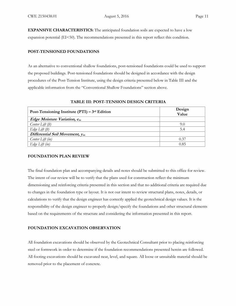
As an alternative to conventional shallow foundations, post-tensioned foundations could be used to support
the proposed buildings. Post-tensioned foundations should be designed in accordance with the design
procedures of the Post-Tension Institute, using the design criteria presented below in Table III and the
applicable information from the “Conventional Shallow Foundations” section above.
TABLE III: POST-TENSION DESIGN CRITERIA
Post-Tensioning Institute (PTI) – 3rd Edition DesignValue
Edge Moisture Variation, emCenter Lift (ft) 9.0Edge Lift (ft) 5.4Differential Soil Movement, ymCenter Lift (in) 0.37Edge Lift (in) 0.85
FOUNDATION PLAN REVIEW
The final foundation plan and accompanying details and notes should be submitted to this office for review.
The intent of our review will be to verify that the plans used for construction reflect the minimum
dimensioning and reinforcing criteria presented in this section and that no additional criteria are required due
to changes in the foundation type or layout. It is not our intent to review structural plans, notes, details, or
calculations to verify that the design engineer has correctly applied the geotechnical design values. It is the
responsibility of the design engineer to properly design/specify the foundations and other structural elements
based on the requirements of the structure and considering the information presented in this report.
FOUNDATION EXCAVATION OBSERVATION
All foundation excavations should be observed by the Geotechnical Consultant prior to placing reinforcing
steel or formwork in order to determine if the foundation recommendations presented herein are followed.
All footing excavations should be excavated neat, level, and square. All loose or unsuitable material should be
removed prior to the placement of concrete.
CWE 2150438.01 August 5, 2016 Page 12
SOLUBLE SUFATES
The water soluble sulfate content was determined in accordance with California Test Method 417 for a
representative soil sample from the site. The result of this test indicates that the representative soil sample
had a soluble sulfate content of 0.016, which is considered negligible.
ON-GRADE SLABS
GENERAL: It is our understanding that the building floors will consist of concrete slabs-on-grade. The
following recommendations are considered the minimum slab requirements based on the soil conditions and are
not intended to be in lieu of structural considerations. Post-tensioned slabs should be specified by the design
engineer.
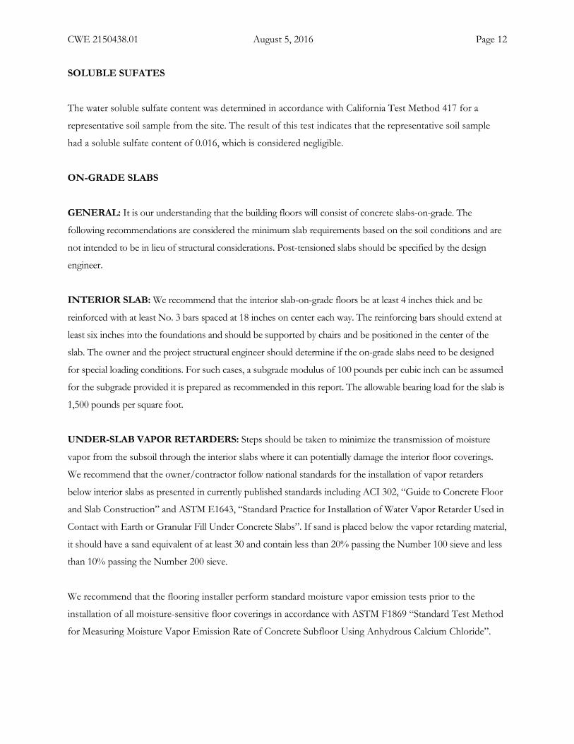
INTERIOR SLAB: We recommend that the interior slab-on-grade floors be at least 4 inches thick and be
reinforced with at least No. 3 bars spaced at 18 inches on center each way. The reinforcing bars should extend at
least six inches into the foundations and should be supported by chairs and be positioned in the center of the
slab. The owner and the project structural engineer should determine if the on-grade slabs need to be designed
for special loading conditions. For such cases, a subgrade modulus of 100 pounds per cubic inch can be assumed
for the subgrade provided it is prepared as recommended in this report. The allowable bearing load for the slab is
1,500 pounds per square foot.
UNDER-SLAB VAPOR RETARDERS: Steps should be taken to minimize the transmission of moisture
vapor from the subsoil through the interior slabs where it can potentially damage the interior floor coverings.
We recommend that the owner/contractor follow national standards for the installation of vapor retarders
below interior slabs as presented in currently published standards including ACI 302, “Guide to Concrete Floor
and Slab Construction” and ASTM E1643, “Standard Practice for Installation of Water Vapor Retarder Used in
Contact with Earth or Granular Fill Under Concrete Slabs”. If sand is placed below the vapor retarding material,
it should have a sand equivalent of at least 30 and contain less than 20% passing the Number 100 sieve and less
than 10% passing the Number 200 sieve.
We recommend that the flooring installer perform standard moisture vapor emission tests prior to the
installation of all moisture-sensitive floor coverings in accordance with ASTM F1869 “Standard Test Method
for Measuring Moisture Vapor Emission Rate of Concrete Subfloor Using Anhydrous Calcium Chloride”.
CWE 2150438.01 August 5, 2016 Page 13
EXTERIOR CONCRETE FLATWORK: Exterior concrete on-grade slabs should have a minimum
thickness of four inches. Exterior slabs abutting perimeter foundations should be doweled into the footings.
All slabs should be provided with weakened plane joints in accordance with the American Concrete Institute
(ACI) guidelines. Alternative patterns consistent with ACI guidelines can also be used. A concrete mix with a
1-inch maximum aggregate size and a water/cement ratio of less than 0.6 is recommended for exterior slabs.
Lower water content will decrease the potential for shrinkage cracks. Both coarse and fine aggregate should
conform to the latest edition of the “Standard Specifications for Public Works Construction” (‘Greenbook”).
Special attention should be paid to the method of concrete curing to reduce the potential for excessive
shrinkage and resultant random cracking. It should be recognized that minor cracks occur normally in
concrete slabs due to shrinkage. Some shrinkage cracks should be expected and are not necessarily an
indication of excessive movement or structural distress.
EARTH RETAINING WALLS
FOUNDATIONS: Foundations for retaining walls can be designed in accordance with the foundation
recommendations previously presented.
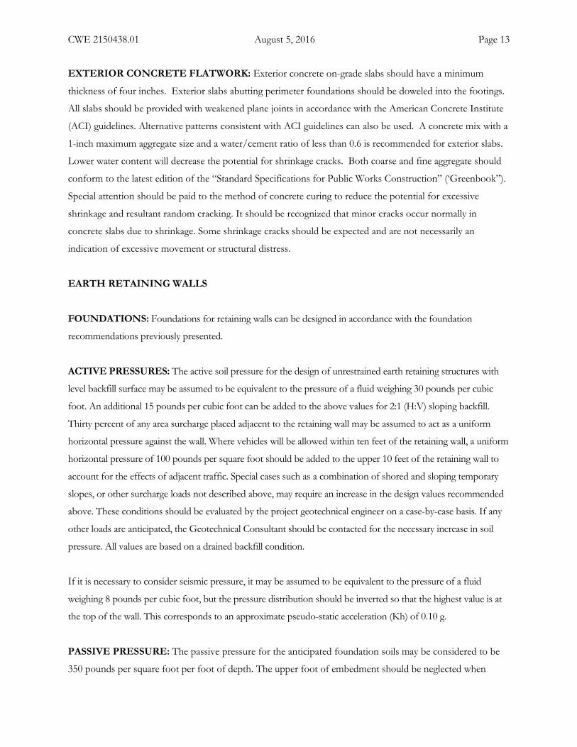
ACTIVE PRESSURES: The active soil pressure for the design of unrestrained earth retaining structures with
level backfill surface may be assumed to be equivalent to the pressure of a fluid weighing 30 pounds per cubic
foot. An additional 15 pounds per cubic foot can be added to the above values for 2:1 (H:V) sloping backfill.
Thirty percent of any area surcharge placed adjacent to the retaining wall may be assumed to act as a uniform
horizontal pressure against the wall. Where vehicles will be allowed within ten feet of the retaining wall, a uniform
horizontal pressure of 100 pounds per square foot should be added to the upper 10 feet of the retaining wall to
account for the effects of adjacent traffic. Special cases such as a combination of shored and sloping temporary
slopes, or other surcharge loads not described above, may require an increase in the design values recommended
above. These conditions should be evaluated by the project geotechnical engineer on a case-by-case basis. If any
other loads are anticipated, the Geotechnical Consultant should be contacted for the necessary increase in soil
pressure. All values are based on a drained backfill condition.
If it is necessary to consider seismic pressure, it may be assumed to be equivalent to the pressure of a fluid
weighing 8 pounds per cubic foot, but the pressure distribution should be inverted so that the highest value is at
the top of the wall. This corresponds to an approximate pseudo-static acceleration (Kh) of 0.10 g.
PASSIVE PRESSURE: The passive pressure for the anticipated foundation soils may be considered to be
350 pounds per square foot per foot of depth. The upper foot of embedment should be neglected when
CWE 2150438.01 August 5, 2016 Page 14
calculating passive pressures, unless the foundation abuts a hard surface such as a concrete slab. The passive
pressure may be increased by one-third for seismic loading. The coefficient of friction for concrete to soil
may be assumed to be 0.35 for the resistance to lateral movement. When combining frictional and passive
resistance, the friction should be reduced by one-third.
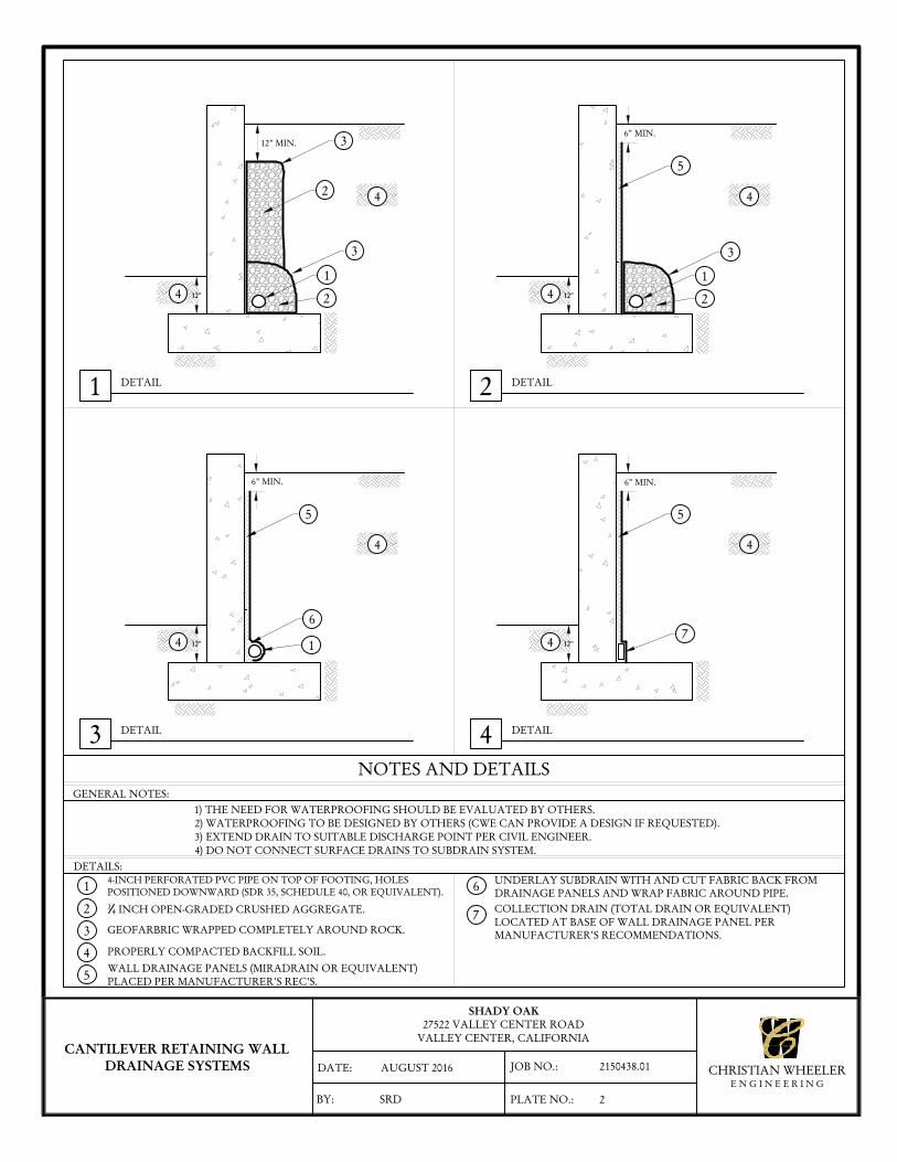
WATERPROOFING AND SUBDRAINS: The project architect should provide (or coordinate)
waterproofing details for the retaining walls. The design values presented above are based on a drained backfill
condition and do not consider hydrostatic pressures. Unless hydrostatic pressures are incorporated into the
design, the retaining wall designer should provide a subdrain detail. A typical retaining wall subdrain detail is
presented as Plate No. 2 of this report. Additionally, outlets points for the retaining wall subdrains should be
coordinated by the project civil engineer.
BACKFILL: All retaining wall backfill should be compacted to at least 90 percent relative compaction. It is
anticipated that the on-site soils are suitable for use as backfill material provided the design parameters given
herein are used in the wall design. Wall backfill material should be free of rocks or lumps of soil in excess of three
inches in maximum dimension. Retaining walls should not be backfilled until the masonry/concrete has reached
an adequate strength.
PRELIMINARY PAVEMENT SECTIONS
GENERAL: We expect that new pavement will be installed as part of the project. The following presents
preliminary sections for asphalt concrete (AC) or Portland Cement Concrete (PCC) construction. The
pavement sections provided in Table IV and Table VI should be considered preliminary and should be used
for planning purposes only. Final pavement designs should be determined after R-value tests have been
performed in the actual subgrade material in place after grading. Presuming the grading recommendations
presented previously are followed, we estimate that the subgrade soils will have an R-Value of at least 25. The
Traffic Index and Traffic Categories shown below are assumed. The project client and/or civil engineer
should determine whether these assumed values are appropriate for the traffic conditions.
ASPHALT CONCRETE: We expect that the streets and drive aisles will primarily support passenger
vehicles with heavily loaded vehicles such as garbage trucks and large moving vans on a daily basis. Parking
stalls are expected to support primarily passenger vehicles and occasional moving vans. The asphalt concrete
pavement section was calculated using the Caltrans design method using an assumed Traffic Index of 5.5 for
interior streets and drive aisles and 4.5 for parking stalls.
CWE 2150438.01 August 5, 2016 Page 15
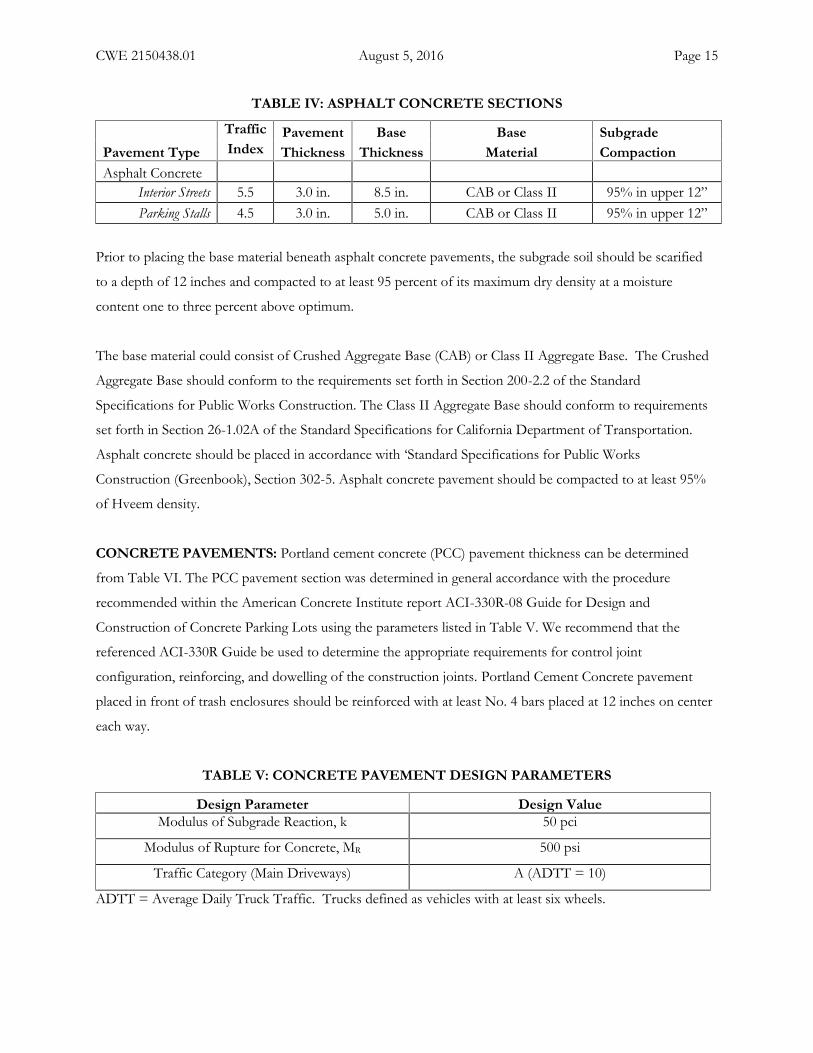
TABLE IV: ASPHALT CONCRETE SECTIONS
Traffic Pavement Base Base SubgradePavement Type Index Thickness Thickness Material CompactionAsphalt Concrete
Interior Streets 5.5 3.0 in. 8.5 in. CAB or Class II 95% in upper 12”Parking Stalls 4.5 3.0 in. 5.0 in. CAB or Class II 95% in upper 12”
Prior to placing the base material beneath asphalt concrete pavements, the subgrade soil should be scarified
to a depth of 12 inches and compacted to at least 95 percent of its maximum dry density at a moisture
content one to three percent above optimum.
The base material could consist of Crushed Aggregate Base (CAB) or Class II Aggregate Base. The Crushed
Aggregate Base should conform to the requirements set forth in Section 200-2.2 of the Standard
Specifications for Public Works Construction. The Class II Aggregate Base should conform to requirements
set forth in Section 26-1.02A of the Standard Specifications for California Department of Transportation.
Asphalt concrete should be placed in accordance with ‘Standard Specifications for Public Works
Construction (Greenbook), Section 302-5. Asphalt concrete pavement should be compacted to at least 95%
of Hveem density.
CONCRETE PAVEMENTS: Portland cement concrete (PCC) pavement thickness can be determined
from Table VI. The PCC pavement section was determined in general accordance with the procedure
recommended within the American Concrete Institute report ACI-330R-08 Guide for Design and
Construction of Concrete Parking Lots using the parameters listed in Table V. We recommend that the
referenced ACI-330R Guide be used to determine the appropriate requirements for control joint
configuration, reinforcing, and dowelling of the construction joints. Portland Cement Concrete pavement
placed in front of trash enclosures should be reinforced with at least No. 4 bars placed at 12 inches on center
each way.
TABLE V: CONCRETE PAVEMENT DESIGN PARAMETERS
Design Parameter Design ValueModulus of Subgrade Reaction, k 50 pci
Modulus of Rupture for Concrete, MR 500 psi
Traffic Category (Main Driveways) A (ADTT = 10)
ADTT = Average Daily Truck Traffic. Trucks defined as vehicles with at least six wheels.
CWE 2150438.01 August 5, 2016 Page 16
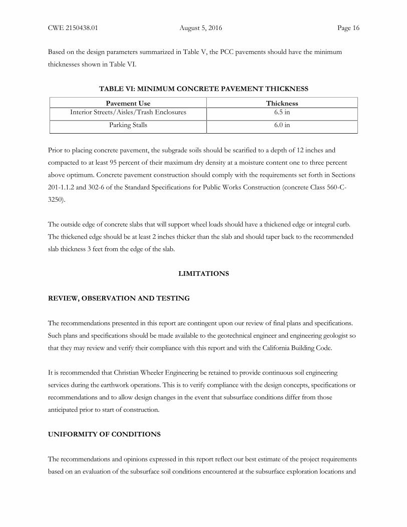
Based on the design parameters summarized in Table V, the PCC pavements should have the minimum
thicknesses shown in Table VI.
TABLE VI: MINIMUM CONCRETE PAVEMENT THICKNESS
Pavement Use ThicknessInterior Streets/Aisles/Trash Enclosures 6.5 in
Parking Stalls 6.0 in
Prior to placing concrete pavement, the subgrade soils should be scarified to a depth of 12 inches and
compacted to at least 95 percent of their maximum dry density at a moisture content one to three percent
above optimum. Concrete pavement construction should comply with the requirements set forth in Sections
201-1.1.2 and 302-6 of the Standard Specifications for Public Works Construction (concrete Class 560-C-
3250).
The outside edge of concrete slabs that will support wheel loads should have a thickened edge or integral curb.
The thickened edge should be at least 2 inches thicker than the slab and should taper back to the recommended
slab thickness 3 feet from the edge of the slab.
LIMITATIONS
REVIEW, OBSERVATION AND TESTING
The recommendations presented in this report are contingent upon our review of final plans and specifications.
Such plans and specifications should be made available to the geotechnical engineer and engineering geologist so
that they may review and verify their compliance with this report and with the California Building Code.
It is recommended that Christian Wheeler Engineering be retained to provide continuous soil engineering
services during the earthwork operations. This is to verify compliance with the design concepts, specifications or
recommendations and to allow design changes in the event that subsurface conditions differ from those
anticipated prior to start of construction.
UNIFORMITY OF CONDITIONS
The recommendations and opinions expressed in this report reflect our best estimate of the project requirements
based on an evaluation of the subsurface soil conditions encountered at the subsurface exploration locations and
CWE 2150438.01 August 5, 2016 Page 17
on the assumption that the soil conditions do not deviate appreciably from those encountered. It should be
recognized that the performance of the foundations and/or cut and fill slopes may be influenced by undisclosed
or unforeseen variations in the soil conditions that may occur in the intermediate and unexplored areas. Any
unusual conditions not covered in this report that may be encountered during site development should be
brought to the attention of the geotechnical engineer so that he may make modifications if necessary.
CHANGE IN SCOPE
This office should be advised of any changes in the project scope or proposed site grading so that we may
determine if the recommendations contained herein are appropriate. This should be verified in writing or
modified by a written addendum.
TIME LIMITATIONS
The findings of this report are valid as of this date. Changes in the condition of a property can, however, occur
with the passage of time, whether they be due to natural processes or the work of man on this or adjacent
properties. In addition, changes in the Standards-of-Practice and/or Government Codes may occur. Due to such
changes, the findings of this report may be invalidated wholly or in part by changes beyond our control.
Therefore, this report should not be relied upon after a period of two years without a review by us verifying the
suitability of the conclusions and recommendations.
PROFESSIONAL STANDARD
In the performance of our professional services, we comply with that level of care and skill ordinarily exercised by
members of our profession currently practicing under similar conditions and in the same locality. The client
recognizes that subsurface conditions may vary from those encountered at the locations where our test pits,
surveys, and explorations are made, and that our data, interpretations, and recommendations be based solely on
the information obtained by us. We will be responsible for those data, interpretations, and recommendations, but
shall not be responsible for the interpretations by others of the information developed. Our services consist of
professional consultation and observation only, and no warranty of any kind whatsoever, express or implied, is
made or intended in connection with the work performed or to be performed by us, or by our proposal for
consulting or other services, or by our furnishing of oral or written reports or findings.
CWE 2150438.01 August 5, 2016 Page 18
CLIENT'S RESPONSIBILITY
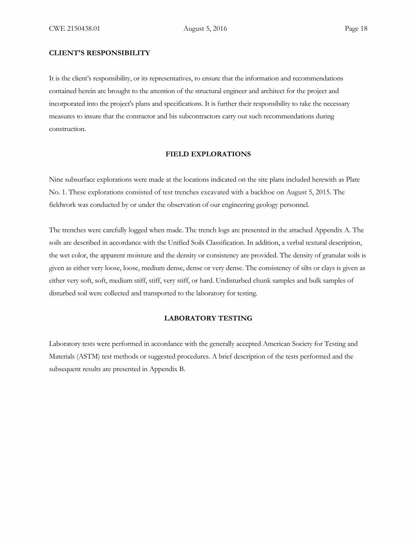
It is the client’s responsibility, or its representatives, to ensure that the information and recommendations
contained herein are brought to the attention of the structural engineer and architect for the project and
incorporated into the project's plans and specifications. It is further their responsibility to take the necessary
measures to insure that the contractor and his subcontractors carry out such recommendations during
construction.
FIELD EXPLORATIONS
Nine subsurface explorations were made at the locations indicated on the site plans included herewith as Plate
No. 1. These explorations consisted of test trenches excavated with a backhoe on August 5, 2015. The
fieldwork was conducted by or under the observation of our engineering geology personnel.
The trenches were carefully logged when made. The trench logs are presented in the attached Appendix A. The
soils are described in accordance with the Unified Soils Classification. In addition, a verbal textural description,
the wet color, the apparent moisture and the density or consistency are provided. The density of granular soils is
given as either very loose, loose, medium dense, dense or very dense. The consistency of silts or clays is given as
either very soft, soft, medium stiff, stiff, very stiff, or hard. Undisturbed chunk samples and bulk samples of
disturbed soil were collected and transported to the laboratory for testing.
LABORATORY TESTING
Laboratory tests were performed in accordance with the generally accepted American Society for Testing and
Materials (ASTM) test methods or suggested procedures. A brief description of the tests performed and the
subsequent results are presented in Appendix B.
T-9
T-4T-3
T-2
T-5
T-7
T-6
T-1
T-8
Kgr
Kgr
Kgr
QafKgr
DATE: AUGUST 2016
BY: SRD
JOB NO.: 2150438.01
PLATE NO.: 1
SITE PLAN AND GEOTECHNICAL MAP
SHADY OAK27522 VALLEY CENTER ROAD
VALLEY CENTER, CALIFORNIA
CHRISTIAN WHEELERE N G I N E E R I N G
APPROXIMATE TRENCH LOCATION
APPROXIMATE GEOLOGIC CONTACT
ARTIFICIAL FILL OVERWEATHERED GRANITICS
WEATHERED GRANITICS
T-9
Kgr
QafKgr
CWE LEGEND
00 50' 100'
SCALE: 1" = 50'
1
3
5
5 5
1
1
3
2
2
3 4NOTES AND DETAILS
1
GENERAL NOTES:1) THE NEED FOR WATERPROOFING SHOULD BE EVALUATED BY OTHERS.2) WATERPROOFING TO BE DESIGNED BY OTHERS (CWE CAN PROVIDE A DESIGN IF REQUESTED).3) EXTEND DRAIN TO SUITABLE DISCHARGE POINT PER CIVIL ENGINEER.4) DO NOT CONNECT SURFACE DRAINS TO SUBDRAIN SYSTEM.
4
2
3
4
5
UNDERLAY SUBDRAIN WITH AND CUT FABRIC BACK FROMDRAINAGE PANELS AND WRAP FABRIC AROUND PIPE.COLLECTION DRAIN (TOTAL DRAIN OR EQUIVALENT)LOCATED AT BASE OF WALL DRAINAGE PANEL PERMANUFACTURER'S RECOMMENDATIONS.
4
3
6
4
4
4
4
4
47
4-INCH PERFORATED PVC PIPE ON TOP OF FOOTING, HOLESPOSITIONED DOWNWARD (SDR 35, SCHEDULE 40, OR EQUIVALENT).3
4 INCH OPEN-GRADED CRUSHED AGGREGATE.
GEOFARBRIC WRAPPED COMPLETELY AROUND ROCK.
PROPERLY COMPACTED BACKFILL SOIL.
WALL DRAINAGE PANELS (MIRADRAIN OR EQUIVALENT)PLACED PER MANUFACTURER'S REC'S.
DETAILS:
6
7
12"
12" 12"
12"
12" MIN.6" MIN.
6" MIN.6" MIN.
1
DETAIL
2 2
DETAIL
DETAIL DETAIL
SHADY OAK27522 VALLEY CENTER ROAD
VALLEY CENTER, CALIFORNIA
DATE: AUGUST 2016
BY: SRD
JOB NO.: 2150438.01
PLATE NO.: 2
CANTILEVER RETAINING WALLDRAINAGE SYSTEMS CHRISTIAN WHEELER
E N G I N E E R I N G

Appendix ATrench Logs


Appendix BLaboratory Test Results
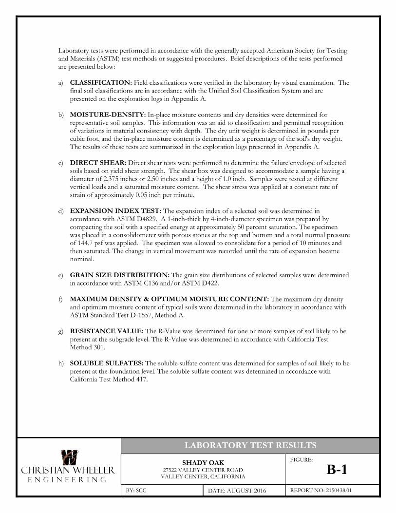
Laboratory tests were performed in accordance with the generally accepted American Society for Testingand Materials (ASTM) test methods or suggested procedures. Brief descriptions of the tests performedare presented below:
a) CLASSIFICATION: Field classifications were verified in the laboratory by visual examination. Thefinal soil classifications are in accordance with the Unified Soil Classification System and arepresented on the exploration logs in Appendix A.
b) MOISTURE-DENSITY: In-place moisture contents and dry densities were determined forrepresentative soil samples. This information was an aid to classification and permitted recognitionof variations in material consistency with depth. The dry unit weight is determined in pounds percubic foot, and the in-place moisture content is determined as a percentage of the soil's dry weight.The results of these tests are summarized in the exploration logs presented in Appendix A.
c) DIRECT SHEAR: Direct shear tests were performed to determine the failure envelope of selectedsoils based on yield shear strength. The shear box was designed to accommodate a sample having adiameter of 2.375 inches or 2.50 inches and a height of 1.0 inch. Samples were tested at differentvertical loads and a saturated moisture content. The shear stress was applied at a constant rate ofstrain of approximately 0.05 inch per minute.
d) EXPANSION INDEX TEST: The expansion index of a selected soil was determined inaccordance with ASTM D4829. A 1-inch-thick by 4-inch-diameter specimen was prepared bycompacting the soil with a specified energy at approximately 50 percent saturation. The specimenwas placed in a consolidometer with porous stones at the top and bottom and a total normal pressureof 144.7 psf was applied. The specimen was allowed to consolidate for a period of 10 minutes andthen saturated. The change in vertical movement was recorded until the rate of expansion becamenominal.
e) GRAIN SIZE DISTRIBUTION: The grain size distributions of selected samples were determinedin accordance with ASTM C136 and/or ASTM D422.
f) MAXIMUM DENSITY & OPTIMUM MOISTURE CONTENT: The maximum dry densityand optimum moisture content of typical soils were determined in the laboratory in accordance withASTM Standard Test D-1557, Method A.
g) RESISTANCE VALUE: The R-Value was determined for one or more samples of soil likely to bepresent at the subgrade level. The R-Value was determined in accordance with California TestMethod 301.
h) SOLUBLE SULFATES: The soluble sulfate content was determined for samples of soil likely to bepresent at the foundation level. The soluble sulfate content was determined in accordance withCalifornia Test Method 417.
CHRISTIAN WHEELERE N G I N E E R I N G
LABORATORY TEST RESULTS
SHADY OAK27522 VALLEY CENTER ROAD
VALLEY CENTER, CALIFORNIA
BY: SCC DATE: AUGUST 2016 REPORT NO: 2150438.01
FIGURE:
B-1
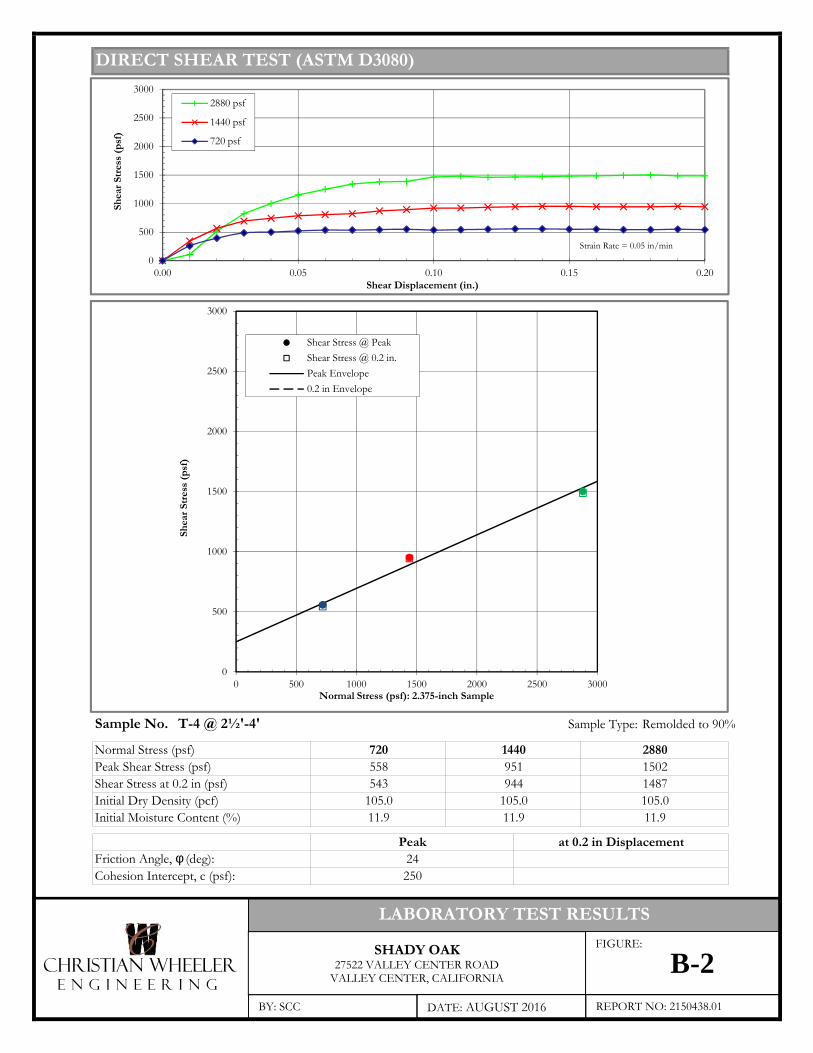
DIRECT SHEAR TEST (ASTM D3080)
Remolded to 90%Undisturbed (Ring)
Sample No. T-4 @ 2½'-4' Sample Type: Remolded to 90%
Normal Stress (psf)Peak Shear Stress (psf)Shear Stress at 0.2 in (psf)Initial Dry Density (pcf)Initial Moisture Content (%)
Friction Angle, φ (deg):Cohesion Intercept, c (psf):
720 1440 2880558 951 1502543 944 1487
105.0 105.0 105.011.9 11.9 11.9
Peak24250
at 0.2 in Displacement
0
500
1000
1500
2000
2500
3000
0 500 1000 1500 2000 2500 3000
Shea
r Stre
ss (p
sf)
Normal Stress (psf): 2.375-inch Sample
Shear Stress @ PeakShear Stress @ 0.2 in.Peak Envelope0.2 in Envelope
0
500
1000
1500
2000
2500
3000
0.00 0.05 0.10 0.15 0.20
Shea
r Stre
ss (p
sf)
Shear Displacement (in.)
2880 psf
1440 psf
720 psf
Strain Rate = 0.05 in/min
CHRISTIAN WHEELERE N G I N E E R I N G
LABORATORY TEST RESULTS
SHADY OAK27522 VALLEY CENTER ROAD
VALLEY CENTER, CALIFORNIA
BY: SCC DATE: AUGUST 2016 REPORT NO: 2150438.01
FIGURE:
B-2
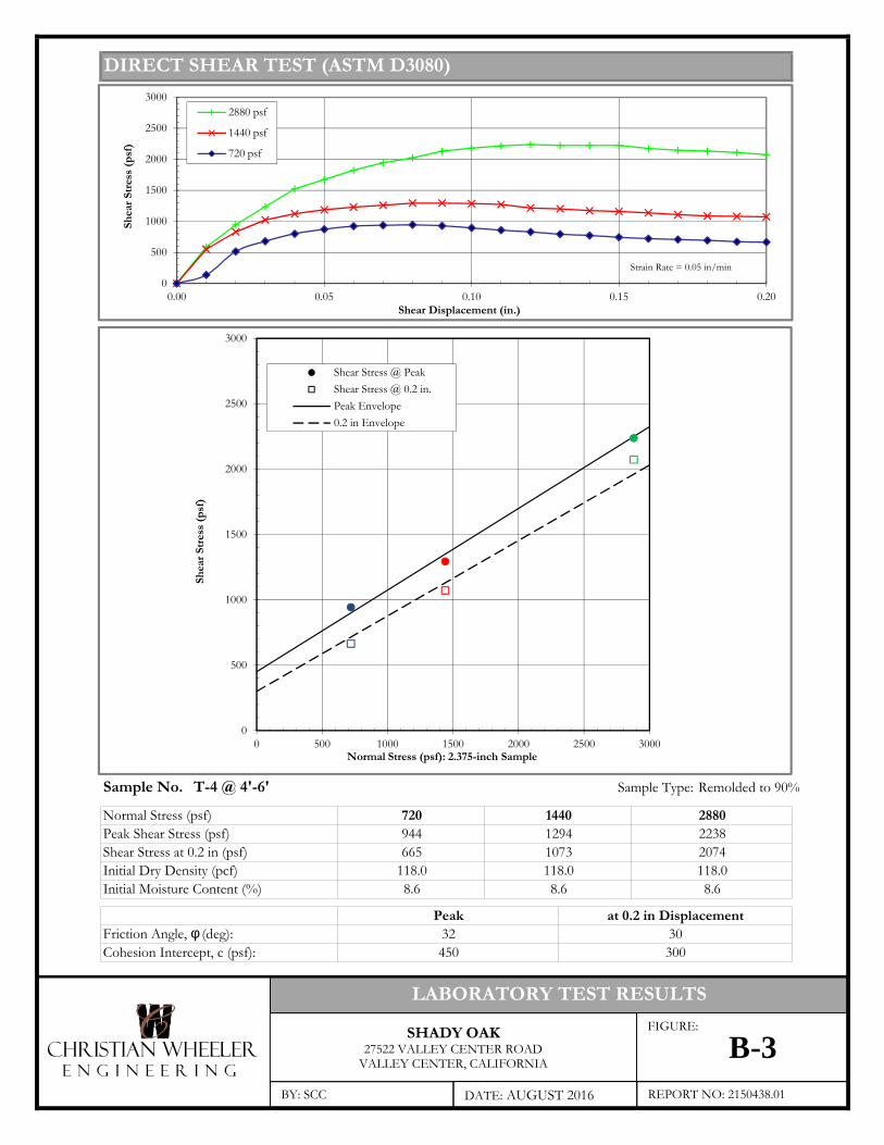
DIRECT SHEAR TEST (ASTM D3080)
Remolded to 90%Undisturbed (Ring)
Sample No. T-4 @ 4'-6' Sample Type: Remolded to 90%
Normal Stress (psf)Peak Shear Stress (psf)Shear Stress at 0.2 in (psf)Initial Dry Density (pcf)Initial Moisture Content (%)
Friction Angle, φ (deg):Cohesion Intercept, c (psf):
720 1440 2880944 1294 2238665 1073 2074
118.0 118.0 118.08.6 8.6 8.6
Peak at 0.2 in Displacement32 30450 300
0
500
1000
1500
2000
2500
3000
0 500 1000 1500 2000 2500 3000
Shea
r Stre
ss (p
sf)
Normal Stress (psf): 2.375-inch Sample
Shear Stress @ PeakShear Stress @ 0.2 in.Peak Envelope0.2 in Envelope
0
500
1000
1500
2000
2500
3000
0.00 0.05 0.10 0.15 0.20
Shea
r Stre
ss (p
sf)
Shear Displacement (in.)
2880 psf
1440 psf
720 psf
Strain Rate = 0.05 in/min
CHRISTIAN WHEELERE N G I N E E R I N G
LABORATORY TEST RESULTS
SHADY OAK27522 VALLEY CENTER ROAD
VALLEY CENTER, CALIFORNIA
BY: SCC DATE: AUGUST 2016 REPORT NO: 2150438.01
FIGURE:
B-3

EXPANSION INDEX (ASTM D2849)
Initial Initial Final Expansion ExpansionMoisture Dry Density Moisture Index Potential
(%) (pcf) (%)
T-4 @ 2½'-4' 10.1 107.6 21.7 35 Low
Expansion Index Expansion Potential1-20 Very Low21-50 Low51-90 Medium91-130 High> 130 Very High
Sample No.
CLASSIFICATION OF EXPANSION POTENTIAL
CHRISTIAN WHEELERE N G I N E E R I N G
LABORATORY TEST RESULTS
SHADY OAK27522 VALLEY CENTER ROAD
VALLEY CENTER, CALIFORNIA
BY: SCC DATE: AUGUST 2016 REPORT NO: 2150438.01
FIGURE:
B-4
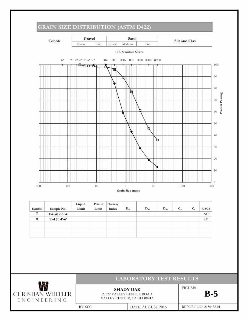
GRAIN SIZE DISTRIBUTION (ASTM D422)
Coarse Fine Coarse Medium Fine
Liquid Plastic PlasticityLimit Limit Index D10 D30 D60 Cu Cc USCS
SCSM
Silt and ClayCobble
Sample No.SymbolT-4 @ 2½'-4'▫
Gravel Sand
♦ T-4 @ 4'-6'
6" 3" 2"1½" 1"¾" ½" #4 #8 #16 #30 #50 #100 #200
0
10
20
30
40
50
60
70
80
90
100
0.0010.010.11101001000Grain Size (mm)
U.S. Standard Sieves
Perc
ent P
assi
ng
CHRISTIAN WHEELERE N G I N E E R I N G
LABORATORY TEST RESULTS
SHADY OAK27522 VALLEY CENTER ROAD
VALLEY CENTER, CALIFORNIA
BY: SCC DATE: AUGUST 2016 REPORT NO: 2150438.01
FIGURE:
B-5
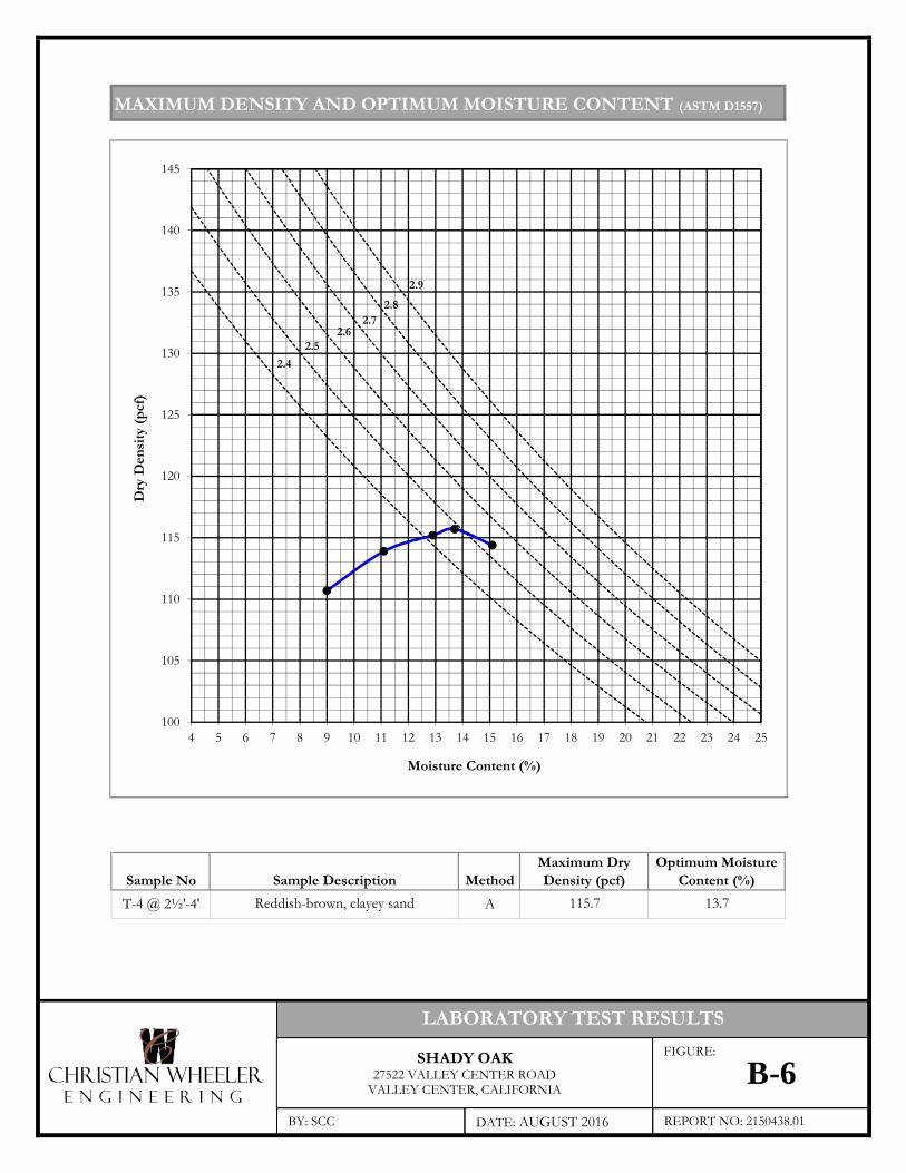
MAXIMUM DENSITY AND OPTIMUM MOISTURE CONTENT (ASTM D1557)
Sample No MethodT-4 @ 2½'-4' A
Maximum DryDensity (pcf)
Optimum MoistureContent (%)Sample Description
115.7 13.7Reddish-brown, clayey sand
100
105
110
115
120
125
130
135
140
145
4 5 6 7 8 9 10 11 12 13 14 15 16 17 18 19 20 21 22 23 24 25
Dry
Den
sity
(pcf
)
Moisture Content (%)
2.92.8
2.72.6
2.52.4
CHRISTIAN WHEELERE N G I N E E R I N G
LABORATORY TEST RESULTS
SHADY OAK27522 VALLEY CENTER ROAD
VALLEY CENTER, CALIFORNIA
BY: SCC DATE: AUGUST 2016 REPORT NO: 2150438.01
FIGURE:
B-6
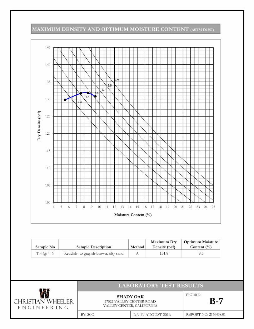
MAXIMUM DENSITY AND OPTIMUM MOISTURE CONTENT (ASTM D1557)
Sample No MethodT-4 @ 4'-6' A
Sample DescriptionMaximum DryDensity (pcf)
Optimum MoistureContent (%)
Reddish- to grayish-brown, silty sand 131.8 8.5
100
105
110
115
120
125
130
135
140
145
4 5 6 7 8 9 10 11 12 13 14 15 16 17 18 19 20 21 22 23 24 25
Dry
Den
sity
(pcf
)
Moisture Content (%)
2.92.8
2.72.6
2.52.4
CHRISTIAN WHEELERE N G I N E E R I N G
LABORATORY TEST RESULTS
SHADY OAK27522 VALLEY CENTER ROAD
VALLEY CENTER, CALIFORNIA
BY: SCC DATE: AUGUST 2016 REPORT NO: 2150438.01
FIGURE:
B-7
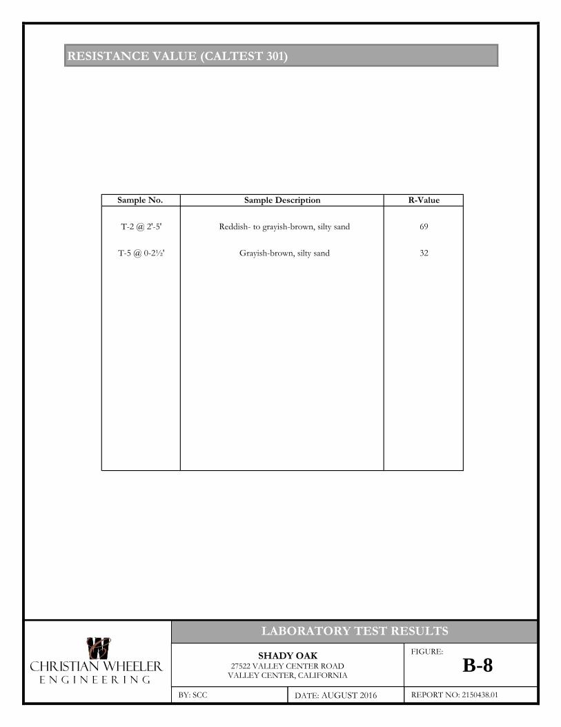
RESISTANCE VALUE (CALTEST 301)
Sample No. R-Value
T-2 @ 2'-5' Reddish- to grayish-brown, silty sand 69
T-5 @ 0-2½' Grayish-brown, silty sand 32
Sample Description
CHRISTIAN WHEELERE N G I N E E R I N G
LABORATORY TEST RESULTS
SHADY OAK27522 VALLEY CENTER ROAD
VALLEY CENTER, CALIFORNIA
BY: SCC DATE: AUGUST 2016 REPORT NO: 2150438.01
FIGURE:
B-8
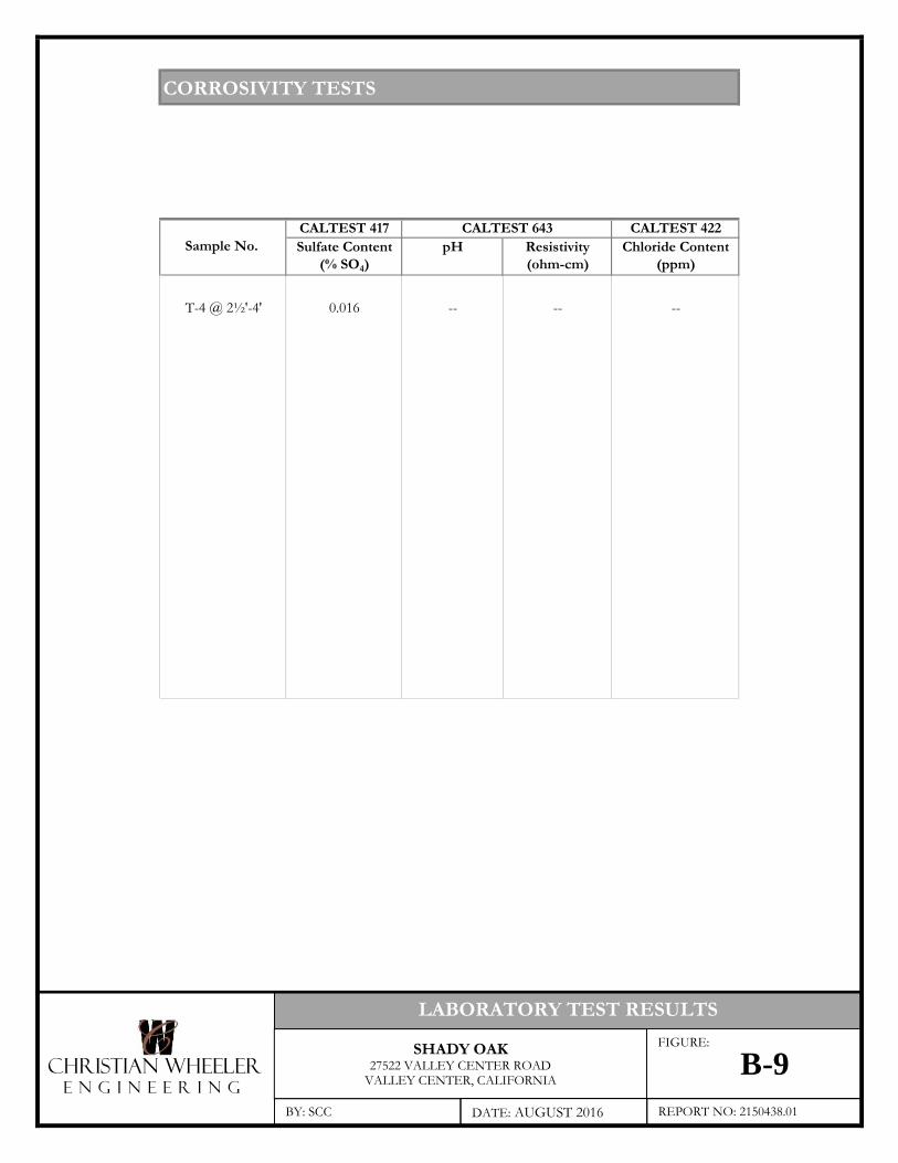
CORROSIVITY TESTS
CALTEST 417 CALTEST 422Sulfate Content pH Resistivity Chloride Content
(% SO4) (ohm-cm) (ppm)
T-4 @ 2½'-4' 0.016 -- -- --
CALTEST 643Sample No.
CHRISTIAN WHEELERE N G I N E E R I N G
LABORATORY TEST RESULTS
SHADY OAK27522 VALLEY CENTER ROAD
VALLEY CENTER, CALIFORNIA
BY: SCC DATE: AUGUST 2016 REPORT NO: 2150438.01
FIGURE:
B-9

Appendix CReferences
CWE 2150438.01 August 5, 2016 Appendix C, Page C-1
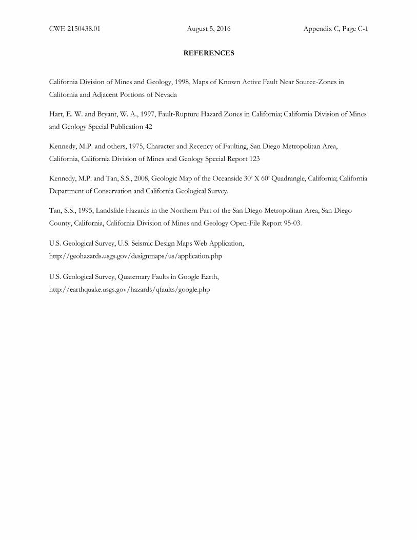
REFERENCES
California Division of Mines and Geology, 1998, Maps of Known Active Fault Near Source-Zones in
California and Adjacent Portions of Nevada
Hart, E. W. and Bryant, W. A., 1997, Fault-Rupture Hazard Zones in California; California Division of Mines
and Geology Special Publication 42
Kennedy, M.P. and others, 1975, Character and Recency of Faulting, San Diego Metropolitan Area,
California, California Division of Mines and Geology Special Report 123
Kennedy, M.P. and Tan, S.S., 2008, Geologic Map of the Oceanside 30’ X 60’ Quadrangle, California; California
Department of Conservation and California Geological Survey.
Tan, S.S., 1995, Landslide Hazards in the Northern Part of the San Diego Metropolitan Area, San Diego
County, California, California Division of Mines and Geology Open-File Report 95-03.
U.S. Geological Survey, U.S. Seismic Design Maps Web Application,
http://geohazards.usgs.gov/designmaps/us/application.php
U.S. Geological Survey, Quaternary Faults in Google Earth,
http://earthquake.usgs.gov/hazards/qfaults/google.php

Appendix DRecommended Grading Specifications – General Provisions
CWE 2150438.01 August 5, 2016 Appendix D, Page D - 1
RECOMMENDED GRADING SPECIFICATIONS - GENERAL PROVISIONS
SHADY OAK
27522 VALLEY CENTER ROADVALLEY CENTER, CALIFORNIA
GENERAL INTENT
The intent of these specifications is to establish procedures for clearing, compacting natural ground,
preparing areas to be filled, and placing and compacting fill soils to the lines and grades shown on the
accepted plans. The recommendations contained in the preliminary geotechnical investigation report
and/or the attached Special Provisions are a part of the Recommended Grading Specifications and shall
supersede the provisions contained hereinafter in the case of conflict. These specifications shall only be
used in conjunction with the geotechnical report for which they are a part. No deviation from these
specifications will be allowed, except where specified in the geotechnical report or in other written
communication signed by the Geotechnical Engineer.
OBSERVATION AND TESTING
Christian Wheeler Engineering shall be retained as the Geotechnical Engineer to observe and test the
earthwork in accordance with these specifications. It will be necessary that the Geotechnical Engineer or
his representative provide adequate observation so that he may provide his opinion as to whether or not
the work was accomplished as specified. It shall be the responsibility of the contractor to assist the
Geotechnical Engineer and to keep him appraised of work schedules, changes and new information and
data so that he may provide these opinions. In the event that any unusual conditions not covered by the
special provisions or preliminary geotechnical report are encountered during the grading operations, the
Geotechnical Engineer shall be contacted for further recommendations.
If, in the opinion of the Geotechnical Engineer, substandard conditions are encountered, such as
questionable or unsuitable soil, unacceptable moisture content, inadequate compaction, adverse weather,
etc., construction should be stopped until the conditions are remedied or corrected or he shall
recommend rejection of this work.
Tests used to determine the degree of compaction should be performed in accordance with the following
American Society for Testing and Materials test methods:
CWE 2150438.01 August 5, 2016 Appendix D, Page D - 2
Maximum Density & Optimum Moisture Content - ASTM D-1557
Density of Soil In-Place - ASTM D-1556 or ASTM D-6938
All densities shall be expressed in terms of Relative Compaction as determined by the foregoing ASTM
testing procedures.
PREPARATION OF AREAS TO RECEIVE FILL
All vegetation, brush and debris derived from clearing operations shall be removed, and legally disposed
of. All areas disturbed by site grading should be left in a neat and finished appearance, free from
unsightly debris.
After clearing or benching the natural ground, the areas to be filled shall be scarified to a depth of 6
inches, brought to the proper moisture content, compacted and tested for the specified minimum degree
of compaction. All loose soils in excess of 6 inches thick should be removed to firm natural ground
which is defined as natural soil which possesses an in-situ density of at least 90 percent of its maximum
dry density.
When the slope of the natural ground receiving fill exceeds 20 percent (5 horizontal units to 1 vertical
unit), the original ground shall be stepped or benched. Benches shall be cut to a firm competent
formational soil. The lower bench shall be at least 10 feet wide or 1-1/2 times the equipment width,
whichever is greater, and shall be sloped back into the hillside at a gradient of not less than two (2)
percent. All other benches should be at least 6 feet wide. The horizontal portion of each bench shall be
compacted prior to receiving fill as specified herein for compacted natural ground. Ground slopes flatter
than 20 percent shall be benched when considered necessary by the Geotechnical Engineer.
Any abandoned buried structures encountered during grading operations must be totally removed. All
underground utilities to be abandoned beneath any proposed structure should be removed from within
10 feet of the structure and properly capped off. The resulting depressions from the above described
procedure should be backfilled with acceptable soil that is compacted to the requirements of the
Geotechnical Engineer. This includes, but is not limited to, septic tanks, fuel tanks, sewer lines or leach
lines, storm drains and water lines. Any buried structures or utilities not to be abandoned should be
brought to the attention of the Geotechnical Engineer so that he may determine if any special
recommendation will be necessary.
CWE 2150438.01 August 5, 2016 Appendix D, Page D - 3
All water wells which will be abandoned should be backfilled and capped in accordance to the
requirements set forth by the Geotechnical Engineer. The top of the cap should be at least 4 feet below
finish grade or 3 feet below the bottom of footing whichever is greater. The type of cap will depend on
the diameter of the well and should be determined by the Geotechnical Engineer and/or a qualified
Structural Engineer.
FILL MATERIAL
Materials to be placed in the fill shall be approved by the Geotechnical Engineer and shall be free of
vegetable matter and other deleterious substances. Granular soil shall contain sufficient fine material to
fill the voids. The definition and disposition of oversized rocks and expansive or detrimental soils are
covered in the geotechnical report or Special Provisions. Expansive soils, soils of poor gradation, or soils
with low strength characteristics may be thoroughly mixed with other soils to provide satisfactory fill
material, but only with the explicit consent of the Geotechnical Engineer. Any import material shall be
approved by the Geotechnical Engineer before being brought to the site.
PLACING AND COMPACTION OF FILL
Approved fill material shall be placed in areas prepared to receive fill in layers not to exceed 6 inches in
compacted thickness. Each layer shall have a uniform moisture content in the range that will allow the
compaction effort to be efficiently applied to achieve the specified degree of compaction. Each layer
shall be uniformly compacted to the specified minimum degree of compaction with equipment of
adequate size to economically compact the layer. Compaction equipment should either be specifically
designed for soil compaction or of proven reliability. The minimum degree of compaction to be
achieved is specified in either the Special Provisions or the recommendations contained in the
preliminary geotechnical investigation report.
When the structural fill material includes rocks, no rocks will be allowed to nest and all voids must be
carefully filled with soil such that the minimum degree of compaction recommended in the Special
Provisions is achieved. The maximum size and spacing of rock permitted in structural fills and in non-
structural fills is discussed in the geotechnical report, when applicable.
Field observation and compaction tests to estimate the degree of compaction of the fill will be taken by
the Geotechnical Engineer or his representative. The location and frequency of the tests shall be at the
Geotechnical Engineer's discretion. When the compaction test indicates that a particular layer is at less
CWE 2150438.01 August 5, 2016 Appendix D, Page D - 4
than the required degree of compaction, the layer shall be reworked to the satisfaction of the
Geotechnical Engineer and until the desired relative compaction has been obtained.
Fill slopes shall be compacted by means of sheepsfoot rollers or other suitable equipment. Compaction
by sheepsfoot roller shall be at vertical intervals of not greater than four feet. In addition, fill slopes at a
ratio of two horizontal to one vertical or flatter, should be trackrolled. Steeper fill slopes shall be over-
built and cut-back to finish contours after the slope has been constructed. Slope compaction operations
shall result in all fill material six or more inches inward from the finished face of the slope having a
relative compaction of at least 90 percent of maximum dry density or the degree of compaction specified
in the Special Provisions section of this specification. The compaction operation on the slopes shall be
continued until the Geotechnical Engineer is of the opinion that the slopes will be surficially stable.
Density tests in the slopes will be made by the Geotechnical Engineer during construction of the slopes
to determine if the required compaction is being achieved. Where failing tests occur or other field
problems arise, the Contractor will be notified that day of such conditions by written communication
from the Geotechnical Engineer or his representative in the form of a daily field report.
If the method of achieving the required slope compaction selected by the Contractor fails to produce the
necessary results, the Contractor shall rework or rebuild such slopes until the required degree of
compaction is obtained, at no cost to the Owner or Geotechnical Engineer.
CUT SLOPES
The Engineering Geologist shall inspect cut slopes excavated in rock or lithified formational material
during the grading operations at intervals determined at his discretion. If any conditions not anticipated
in the preliminary report such as perched water, seepage, lenticular or confined strata of a potentially
adverse nature, unfavorably inclined bedding, joints or fault planes are encountered during grading, these
conditions shall be analyzed by the Engineering Geologist and Geotechnical Engineer to determine if
mitigating measures are necessary.
Unless otherwise specified in the geotechnical report, no cut slopes shall be excavated higher or steeper
than that allowed by the ordinances of the controlling governmental agency.
CWE 2150438.01 August 5, 2016 Appendix D, Page D - 5
ENGINEERING OBSERVATION
Field observation by the Geotechnical Engineer or his representative shall be made during the filling and
compaction operations so that he can express his opinion regarding the conformance of the grading with
acceptable standards of practice. Neither the presence of the Geotechnical Engineer or his representative
or the observation and testing shall release the Grading Contractor from his duty to compact all fill
material to the specified degree of compaction.
SEASON LIMITS
Fill shall not be placed during unfavorable weather conditions. When work is interrupted by heavy rain,
filling operations shall not be resumed until the proper moisture content and density of the fill materials
can be achieved. Damaged site conditions resulting from weather or acts of God shall be repaired before
acceptance of work.
RECOMMENDED GRADING SPECIFICATIONS - SPECIAL PROVISIONS
RELATIVE COMPACTION: The minimum degree of compaction to be obtained in compacted
natural ground, compacted fill, and compacted backfill shall be at least 90 percent. For street and parking
lot subgrade, the upper twelve inches should be compacted to at least 95 percent relative compaction.
EXPANSIVE SOILS: Detrimentally expansive soil is defined as clayey soil which has an expansion
index of 50 or greater when tested in accordance with the American Society of Testing Materials (ASTM)
Laboratory Test D4829-95.
OVERSIZED MATERIAL: Oversized fill material is generally defined herein as rocks or lumps of soil
over six inches in diameter. Oversized materials should not be placed in fill unless recommendations of
placement of such material is provided by the Geotechnical Engineer. At least 40 percent of the fill soils
shall pass through a No. 4 U.S. Standard Sieve.
TRANSITION LOTS: Where transitions between cut and fill occur within the proposed building pad,
the cut portion should be undercut a minimum of one foot below the base of the proposed footings and
recompacted as structural backfill. In certain cases that would be addressed in the geotechnical report,
special footing reinforcement or a combination of special footing reinforcement and undercutting may be
required.