geotechnical series 100 report - maine.gov series 100 report route 202 greene, maine ... one hand...
TRANSCRIPT
Maine Department of Transportation Highway Program
GEOTECHNICAL SERIES 100 REPORT
Route 202 Greene, Maine
Prepared by: Scott A. Hayden, C.G.
Soils Research Scientist
Androscoggin County WIN 19010.00 Soils Report No. 2013-114 Fed Project #: AC-STP-1901(000)X TEDOCS# 1267631 February 27, 2013
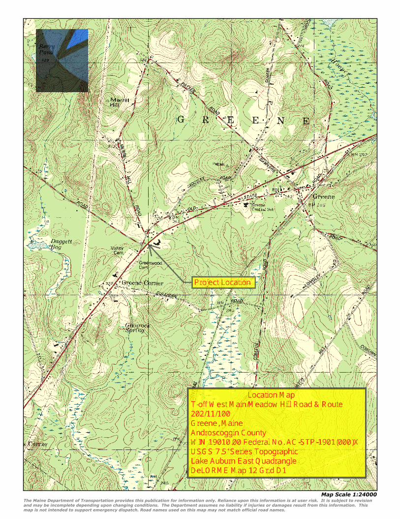
Map Scale 1:24000
The Maine Department of Transportation provides this publication for information only. Reliance upon this information is at user risk. It is subject to revisionand may be incomplete depending upon changing conditions. The Department assumes no liability if injuries or damages result from this information. Thismap is not intended to support emergency dispatch. Road names used on this map may not match official road names.
The Maine Department of Transportation provides this publication for information only. Reliance upon this information is at user risk. It is subject to revision and may be incomplete depending upon changingconditions. The Department assumes no liability if injuries or damages result from this information. This map is not intended to support emergency dispatch. Road names used on this map may not match officialroad names.

Memorandum
DATE: February 27, 2013 TO: Shawn Smith DEPT: Highway, Region 2 FROM: Scott A. Hayden DEPT: Highway Program SUBJECT: 19010.00 Greene Route 202 - Final Soils Report # 2013-114 Project Information A subsurface investigation has been completed for the reconstruction and intersection improvements of Route 202 and West Main Street. The improvements consist of constructing a T intersection with West Main Street/Meadow Hill Road and Route 202. A 1900-foot section of Route 202 is to be widened to accommodate new turn lanes. The purpose of the subsurface investigation was to obtain subsurface soil, bedrock, and ground water information along the proposed project site for design and construction purposes. The investigation included the use of a drill rig, falling weight deflectometer (FWD) and ground penetrating radar (GPR). Subsurface Explorations Subsurface explorations were conducted by Maine DOT using a CME 45C truck mounted drill rig. Bore hole logging was performed by Maine DOT. Power Auger Borings Sixteen power augers borings were conducted along the project site (See Boring Logs). Power auger borings were conducted using 5” solid stem augers. Soils were described and sampled directly from the auger flights. The majority of borings were placed full width at 4 station locations along Route 202 to collect data in the travel lanes and adjacent shoulders to determine and compare the roadway structure.
Left Shoulder Left Travel Right Travel Right Shoulder20' 15' 9' 9' 15' 20'
22+74 X X X X
26+24 X X X X X X
30+74 X X
36+74 X XE P C L E P
X = Power Auger Boring Locations
Highway Program Brad Foley, Program Manager
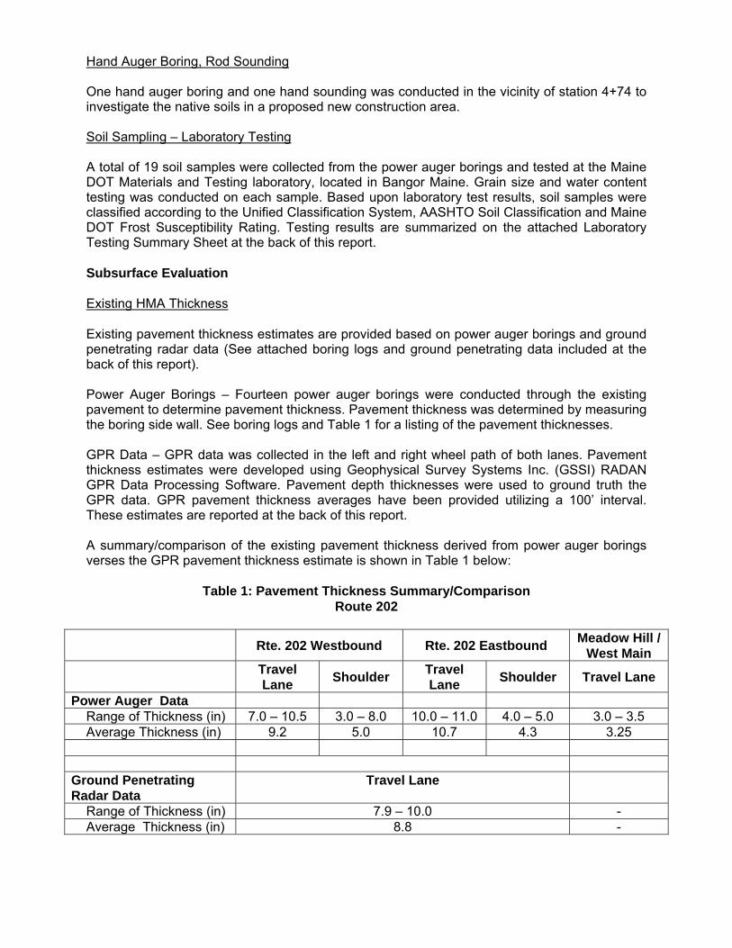
Hand Auger Boring, Rod Sounding One hand auger boring and one hand sounding was conducted in the vicinity of station 4+74 to investigate the native soils in a proposed new construction area. Soil Sampling – Laboratory Testing A total of 19 soil samples were collected from the power auger borings and tested at the Maine DOT Materials and Testing laboratory, located in Bangor Maine. Grain size and water content testing was conducted on each sample. Based upon laboratory test results, soil samples were classified according to the Unified Classification System, AASHTO Soil Classification and Maine DOT Frost Susceptibility Rating. Testing results are summarized on the attached Laboratory Testing Summary Sheet at the back of this report. Subsurface Evaluation Existing HMA Thickness Existing pavement thickness estimates are provided based on power auger borings and ground penetrating radar data (See attached boring logs and ground penetrating data included at the back of this report). Power Auger Borings – Fourteen power auger borings were conducted through the existing pavement to determine pavement thickness. Pavement thickness was determined by measuring the boring side wall. See boring logs and Table 1 for a listing of the pavement thicknesses. GPR Data – GPR data was collected in the left and right wheel path of both lanes. Pavement thickness estimates were developed using Geophysical Survey Systems Inc. (GSSI) RADAN GPR Data Processing Software. Pavement depth thicknesses were used to ground truth the GPR data. GPR pavement thickness averages have been provided utilizing a 100’ interval. These estimates are reported at the back of this report. A summary/comparison of the existing pavement thickness derived from power auger borings verses the GPR pavement thickness estimate is shown in Table 1 below:
Table 1: Pavement Thickness Summary/Comparison Route 202
Rte. 202 Westbound Rte. 202 Eastbound Meadow Hill /
West Main Travel
Lane Shoulder Travel Lane Shoulder Travel Lane
Power Auger Data Range of Thickness (in) 7.0 – 10.5 3.0 – 8.0 10.0 – 11.0 4.0 – 5.0 3.0 – 3.5 Average Thickness (in) 9.2 5.0 10.7 4.3 3.25
Ground Penetrating Radar Data
Travel Lane
Range of Thickness (in) 7.9 – 10.0 - Average Thickness (in) 8.8 -
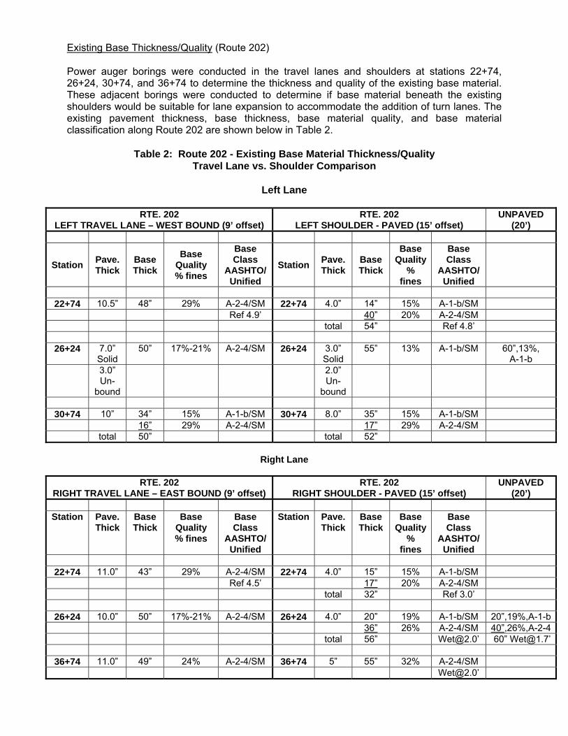
Existing Base Thickness/Quality (Route 202) Power auger borings were conducted in the travel lanes and shoulders at stations 22+74, 26+24, 30+74, and 36+74 to determine the thickness and quality of the existing base material. These adjacent borings were conducted to determine if base material beneath the existing shoulders would be suitable for lane expansion to accommodate the addition of turn lanes. The existing pavement thickness, base thickness, base material quality, and base material classification along Route 202 are shown below in Table 2.
Table 2: Route 202 - Existing Base Material Thickness/Quality
Travel Lane vs. Shoulder Comparison
Left Lane
RTE. 202 LEFT TRAVEL LANE – WEST BOUND (9’ offset)
RTE. 202 LEFT SHOULDER - PAVED (15’ offset)
UNPAVED (20’)
Station Pave. Thick
Base Thick
Base Quality % fines
Base Class
AASHTO/ Unified
Station Pave. Thick
Base Thick
Base Quality
% fines
Base Class
AASHTO/ Unified
22+74 10.5” 48” 29% A-2-4/SM 22+74 4.0” 14” 15% A-1-b/SM
Ref 4.9’ 40” 20% A-2-4/SM total 54” Ref 4.8’
26+24 7.0” Solid
50” 17%-21% A-2-4/SM 26+24 3.0” Solid
55” 13% A-1-b/SM 60”,13%, A-1-b
3.0” Un-
bound
2.0” Un-
bound
30+74 10” 34” 15% A-1-b/SM 30+74 8.0” 35” 15% A-1-b/SM
16” 29% A-2-4/SM 17” 29% A-2-4/SM total 50” total 52”
Right Lane
RTE. 202
RIGHT TRAVEL LANE – EAST BOUND (9’ offset) RTE. 202
RIGHT SHOULDER - PAVED (15’ offset) UNPAVED
(20’)
Station Pave. Thick
Base Thick
Base Quality % fines
Base Class
AASHTO/ Unified
Station Pave. Thick
Base Thick
Base Quality
% fines
Base Class
AASHTO/ Unified
22+74 11.0” 43” 29% A-2-4/SM 22+74 4.0” 15” 15% A-1-b/SM
Ref 4.5’ 17” 20% A-2-4/SM total 32” Ref 3.0’
26+24 10.0” 50” 17%-21% A-2-4/SM 26+24 4.0” 20” 19% A-1-b/SM 20”,19%,A-1-b 36” 26% A-2-4/SM 40”,26%,A-2-4 total 56” [email protected]’ 60” [email protected]’
36+74 11.0” 49” 24% A-2-4/SM 36+74 5” 55” 32% A-2-4/SM [email protected]’

Existing Roadway Base (Route 202) Classification: A-1-b, A-2-4 Percent Passing #200: 15% - 29% Range of Base Material Thickness: 43” – 50” Average Thickness: 48” The existing base generally consists of gravelly SANDS. This granular material was generally encountered full depth at each boring location and is classified (AASHTO / Unified) as an A-2-4 / SM soil. No distinct layers were identified in the borings. Although this base material is classified as granular, the percentage of fines passing the #200 sieve is relatively high. Existing Shoulder Base (Route 202) Classification: A-1-b, A-2-4 Percent Passing #200: 13% - 32% Range of Shoulder Base Material Thickness: 32” – 56” Average Thickness: 50” The existing base materials beneath the shoulders are similar in overall thickness to the granular material underlying the travel lanes. However, the shoulder material differs in that two distinct granular layers were identified in the majority of shoulder borings. The upper layer of granular shoulder material (approximately 14”-20” thick) consists of gravelly SANDS. This layer is slightly more granular than the underlying material and the material encountered beneath the travel lanes. This material is classified (AASHTO / Unified) as an A-1-b / SM soil. The lower granular layer (approximately 17” – 40” thick) is classified (AASHTO / Unified) as an A-2-4 / SM soil similar to the base material encountered beneath the travel lanes. At station 26+24 borings were conducted beyond the paved shoulder area at an offset of 20’ left and 20’ right to determine if granular material was present beyond the paved portion of the shoulder. Granular material similar to that described above was encountered full depth at each boring location. Although the shoulder base material is classified as granular, the percentage of fines passing the #200 sieve is relatively high. Wet soil conditions were encountered as shallow as 1.7’ in borings conducted in the right shoulder at stations 26+24 and 36+74. Existing Roadway Base (Meadow Hill / West Main) Classification: A-1-b Percent Passing #200: 12% - 14% Range of Base Material Thickness: 26” – 42” Average Thickness: 34” The existing roadway base material beneath Meadow Hill Road and West Main Street consists of gravelly SANDS similar to the shoulder base material encountered beneath Route 202. This material is classified (AASHTO / Unified) as an A-1-b / SM soil with 12% - 14% passing the # 200 sieve.

Native Soils Native soils are mapped by the Natural Resources Conservation Service as glaciofluvial deposits. These soils are anticipated to consist of Silty SANDS and Sandy SILTS similar to samples S1, S2 and S4. Samples of these soils indicate relative high silt content (38% - 50%). These soils are moderately frost susceptible. NRCS maps depicting soil type and depth to water table have been included at the back of this report. Bedrock Power auger borings encountered refusals in all four borings conducted at station 22+74. It is anticipated that these refusals are likely due to a shallow bedrock surface. Refusal locations and depths are listed below.
Table 3: Power Auger Refusal Location/Depth Station 15’ Left 9’ Left 9’ Right 15’ Right 22+74 4.8’ Refusal 3.0’ Refusal 4.5’ Refusal 4.9’ Refusal It is anticipated that the bedrock lithology in this area will likely be igneous and would require blasting to remove. New construction is proposed between stations 4+50 and 5+50. A rod sounding was conducted at 4+64, 5’ right, to investigate any potential for shallow bedrock. The rod sounding penetrated to a depth of 8’ without encountering any refusal. Frost Susceptible Soils/Frost Penetration The sandy SILT / Silty SAND native soils are anticipated to be moderately frost susceptible. Frost ratings can be found on the Laboratory Testing Summary Sheet. Frost action in soils requires the presence of frost susceptible soils, ground temperatures below 32° F, and water. Proper drainage of the pavement structure and the lowering or draw down of the ground table through ditching and/or underdrain is critical in minimizing the damaging effects of frost action throughout this project. The Maine Design Freezing Index for this project is approximately 1580. Frost penetration depth beneath a snow free pavement is anticipated to be between 33” (silt or clay) and 80” (sand or gravel) based on the 1955 Army Corps of Engineers, “Prediction of Freezing Temperature Penetration in New England”. Drainage Wet soil conditions were encountered within the existing base layer(s) at stations 26+24 and 36+74 in the eastbound travel and shoulder area. Ditching will be critical in providing pavement structure drainage and water table drawdown if design expectations are to be met. Ditches should be constructed with a minimum depth of 3 feet below finished grade when possible.
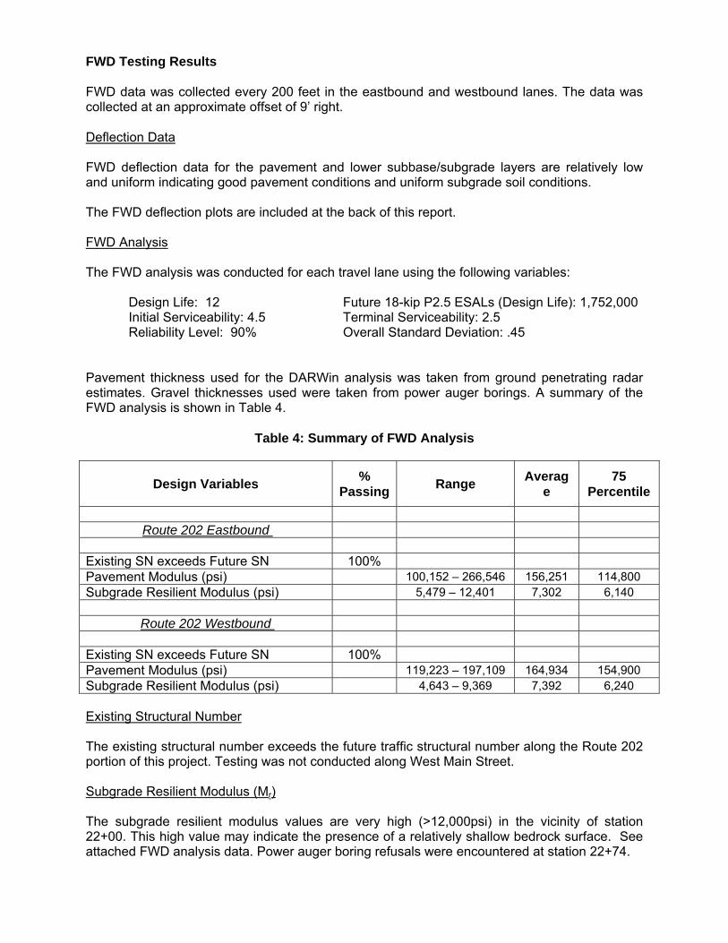
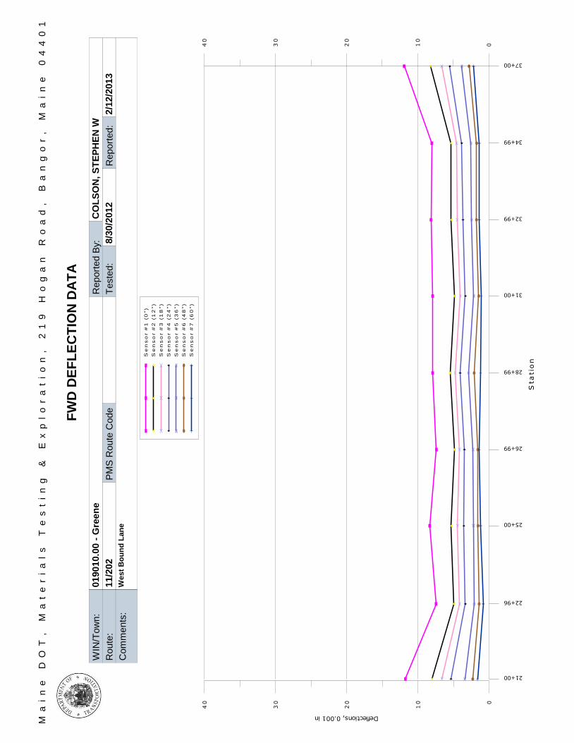
FWD Testing Results FWD data was collected every 200 feet in the eastbound and westbound lanes. The data was collected at an approximate offset of 9’ right. Deflection Data FWD deflection data for the pavement and lower subbase/subgrade layers are relatively low and uniform indicating good pavement conditions and uniform subgrade soil conditions. The FWD deflection plots are included at the back of this report. FWD Analysis The FWD analysis was conducted for each travel lane using the following variables:
Design Life: 12 Future 18-kip P2.5 ESALs (Design Life): 1,752,000 Initial Serviceability: 4.5 Terminal Serviceability: 2.5 Reliability Level: 90% Overall Standard Deviation: .45
Pavement thickness used for the DARWin analysis was taken from ground penetrating radar estimates. Gravel thicknesses used were taken from power auger borings. A summary of the FWD analysis is shown in Table 4.
Table 4: Summary of FWD Analysis
Design Variables % Passing Range Averag
e 75
Percentile
Route 202 Eastbound
Existing SN exceeds Future SN 100% Pavement Modulus (psi) 100,152 – 266,546 156,251 114,800 Subgrade Resilient Modulus (psi) 5,479 – 12,401 7,302 6,140
Route 202 Westbound
Existing SN exceeds Future SN 100% Pavement Modulus (psi) 119,223 – 197,109 164,934 154,900 Subgrade Resilient Modulus (psi) 4,643 – 9,369 7,392 6,240 Existing Structural Number The existing structural number exceeds the future traffic structural number along the Route 202 portion of this project. Testing was not conducted along West Main Street. Subgrade Resilient Modulus (Mr) The subgrade resilient modulus values are very high (>12,000psi) in the vicinity of station 22+00. This high value may indicate the presence of a relatively shallow bedrock surface. See attached FWD analysis data. Power auger boring refusals were encountered at station 22+74.

Conclusions/Recommendations
1. Falling weight deflectometer data and Darwin analysis indicates that the existing structural number meets or exceeds the future structural number along the Route 202 portion of this project.
2. The existing base material beneath the existing travel lanes and shoulders are adequate
in thickness. Based on limited subsurface explorations it is anticipated that the granular base material extends outward to an offset of 20-feet from centerline. The quality of the existing base material is marginal due to relatively high silt content.
3. Wet soil conditions were encountered within the existing base layer(s) at stations 26+24
and 36+74 in the eastbound travel and shoulder area. Ditching will be critical in providing pavement structure drainage and water table drawdown if design expectations are to be met. Ditches should be constructed with a minimum depth of 3 feet below finished grade when possible.
4. Bedrock could be as shallow as 3-feet below the existing pavement surface between
stations 21+00 and 23+00. This relatively shallow bedrock surface may be encountered depending on the final design and construction needs. If bedrock excavation is necessary blasting will be required.
5. According to maintenance personnel there are no differential heaving issues associated
with the possible shallow bedrock surface underlying Route 202 between stations 21+00 and 23+00.
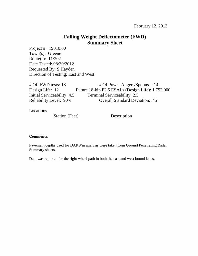
February 12, 2013
Falling Weight Deflectometer (FWD) Summary Sheet
Project #: 19010.00 Town(s): Greene Route(s): 11/202 Date Tested: 08/30/2012 Requested By: S Hayden Direction of Testing: East and West # Of FWD tests: 18 # Of Power Augers/Spoons - 14 Design Life: 12 Future 18-kip P2.5 ESALs (Design Life): 1,752,000 Initial Serviceability: 4.5 Terminal Serviceability: 2.5 Reliability Level: 90% Overall Standard Deviation: .45 Locations Station (Feet) Description Comments: Pavement depths used for DARWin analysis were taken from Ground Penetrating Radar Summary sheets. Data was reported for the right wheel path in both the east and west bound lanes.
WIN
/To
wn
:01
90
10.0
0 -
Gre
en
e
Rou
te:
11
/20
2
Ma
in
e
DO
T,
M
at
er
ia
ls
T
es
ti
ng
&
E
xp
lo
ra
ti
on
,
21
9
Ho
ga
n
Ro
ad
,
Ba
ng
or
,
Ma
in
e
04
40
1
FW
D D
EF
LE
CT
ION
DA
TA
Rep
ort
ed B
y:C
OL
SO
N,
ST
EP
HE
N W
Teste
d:
8/3
0/2
01
2
Com
me
nts
:W
es
t B
ou
nd
Lan
e
PM
S R
ou
te C
ode
Rep
ort
ed:
2/1
2/2
01
3
37+00
34+99
32+99
31+00
28+99
26+99
25+00
22+96
21+00
Sta
tio
n
0
10
20
30
40
Deflections, 0.001 in
Se
ns
or #
1 (
0")
Se
ns
or #
2 (
12
")
Se
ns
or #
3 (
18
")
Se
ns
or #
4 (
24
")
Se
ns
or #
5 (
36
")
Se
ns
or #
6 (
48
")
Se
ns
or #
7 (
60
")
010
20
30
40

WIN
/To
wn
:01
90
10.0
0 -
Gre
en
e
Rou
te:
11
/20
2
Ma
in
e
DO
T,
M
at
er
ia
ls
T
es
ti
ng
&
E
xp
lo
ra
ti
on
,
21
9
Ho
ga
n
Ro
ad
,
Ba
ng
or
,
Ma
in
e
04
40
1
FW
D D
EF
LE
CT
ION
DA
TA
Rep
ort
ed B
y:C
OL
SO
N,
ST
EP
HE
N W
Teste
d:
8/3
0/2
01
2
Com
me
nts
:E
as
t B
ou
nd
Lan
e
PM
S R
ou
te C
ode
Rep
ort
ed:
2/1
2/2
01
3
22+00
24+04
26+05
28+00
30+01
32+11
34+00
36+00
38+00
Sta
tio
n
0
10
20
30
40
Deflections, 0.001 in
Se
ns
or #
1 (
0")
Se
ns
or #
2 (
12
")
Se
ns
or #
3 (
18
")
Se
ns
or #
4 (
24
")
Se
ns
or #
5 (
36
")
Se
ns
or #
6 (
48
")
Se
ns
or #
7 (
60
")
010
20
30
40
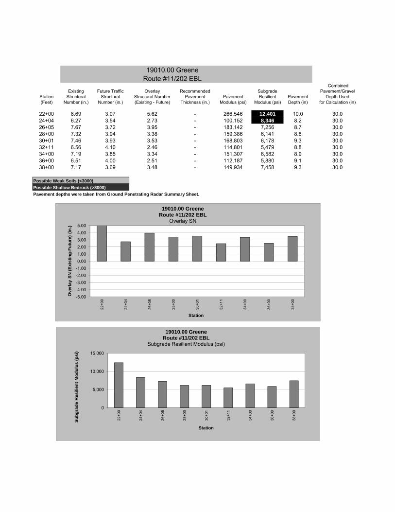
19010.00 GreeneRoute #11/202 EBL
CombinedExisting Future Traffic Overlay Recommended Subgrade Pavement/Gravel
Station Structural Structural Structural Number Pavement Pavement Resilient Pavement Depth Used(Feet) Number (in.) Number (in.) (Existing - Future) Thickness (in.) Modulus (psi) Modulus (psi) Depth (in) for Calculation (in)
22+00 8.69 3.07 5.62 - 266,546 12,401 10.0 30.024+04 6.27 3.54 2.73 - 100,152 8,346 8.2 30.026+05 7.67 3.72 3.95 - 183,142 7,256 8.7 30.028+00 7.32 3.94 3.38 - 159,386 6,141 8.8 30.030+01 7.46 3.93 3.53 - 168,803 6,178 9.3 30.032+11 6.56 4.10 2.46 - 114,801 5,479 8.8 30.034+00 7.19 3.85 3.34 - 151,307 6,582 8.9 30.036+00 6.51 4.00 2.51 - 112,187 5,880 9.1 30.038+00 7.17 3.69 3.48 - 149,934 7,458 9.3 30.0
Possible Weak Soils (<3000)Possible Shallow Bedrock (>8000)Pavement depths were taken from Ground Penetrating Radar Summary Sheet.
0
5,000
10,000
15,000
22+0
0
24+0
4
26+0
5
28+0
0
30+0
1
32+1
1
34+0
0
36+0
0
38+0
0
Subg
rade
Res
ilien
t Mod
ulus
(psi
)
Station
19010.00 GreeneRoute #11/202 EBL
Subgrade Resilient Modulus (psi)
-5.00-4.00-3.00-2.00-1.000.001.002.003.004.005.00
22+0
0
24+0
4
26+0
5
28+0
0
30+0
1
32+1
1
34+0
0
36+0
0
38+0
0
Ove
rlay
SN (E
xist
ing-
Futu
re) (
in.)
Station
19010.00 GreeneRoute #11/202 EBL
Overlay SN

19010.00 GreeneRoute #11/202 WBL
CombinedExisting Future Traffic Overlay Recommended Subgrade Pavement/Gravel
Station Structural Structural Structural Number Pavement Pavement Resilient Pavement Depth Used(Feet) Number (in.) Number (in.) (Existing - Future) Thickness (in.) Modulus (psi) Modulus (psi) Depth (in) for Calculation (in)
21+00 6.64 4.05 2.59 - 119,223 5,690 9.3 30.022+96 7.75 3.40 4.35 - 188,995 9,369 10.0 30.025+00 7.25 3.53 3.72 - 154,901 8,407 8.2 30.026+99 7.76 3.56 4.20 - 189,642 8,237 8.7 30.028+99 7.86 3.92 3.94 - 197,109 6,243 8.8 30.031+00 7.45 3.44 4.01 - 168,054 9,053 9.3 30.032+99 7.54 3.70 3.84 - 173,887 7,395 8.8 30.034+99 7.50 3.68 3.82 - 171,556 7,489 8.7 30.037+00 6.68 4.34 2.34 - 121,036 4,643 9.3 30.0
Possible Weak Soils (<3000)Possible Shallow Bedrock (>8000)Pavement depths were taken from Ground Penetrating Radar Summary Sheet.
0
5,000
10,000
15,000
21+0
0
22+9
6
25+0
0
26+9
9
28+9
9
31+0
0
32+9
9
34+9
9
37+0
0
Subg
rade
Res
ilien
t Mod
ulus
(psi
)
Station
19010.00 GreeneRoute #11/202 WBL
Subgrade Resilient Modulus (psi)
-5.00-4.00-3.00-2.00-1.000.001.002.003.004.005.00
21+0
0
22+9
6
25+0
0
26+9
9
28+9
9
31+0
0
32+9
9
34+9
9
37+0
0
Ove
rlay
SN (E
xist
ing-
Futu
re) (
in.)
Station
19010.00 GreeneRoute #11/202 WBL
Overlay SN

Ma
in
e
DO
T,
M
at
er
ia
ls
T
es
ti
ng
&
E
xp
lo
ra
ti
on
,
21
9
Ho
ga
n
Ro
ad
,
Ba
ng
or
,
Ma
in
e
04
40
1
Gro
un
d P
en
etr
ati
ng
Ra
dar
(GP
R)
Add
itio
na
l C
om
me
nts
Esti
mate
d P
avem
en
t T
hic
kn
ess
Ana
lysis
Dis
tan
ce
, ft
.
10
0
Ove
rall
Ave
rage T
hic
kne
ss,
in.
8.8
Ove
rall
Min
imum
Thic
kn
ess, in
.
7.9
Ove
rall
Maxim
um
Th
ickne
ss,
in.
10
La
ne
Teste
d
MA
INL
INE
01
90
10
.00
- G
ree
ne
Exp
lan
ati
on
of
Gro
un
d P
en
etr
ati
ng
(G
PR
) D
ata
Co
llecti
on
an
d A
na
lysis
:
GP
R d
ata
wa
s c
olle
cte
d in t
he
left
and
rig
ht w
he
el path
of
both
la
nes.
Data
was c
olle
cte
d a
t 1 f
oo
t in
terv
als
alo
ng t
he
en
tire
sectio
n. P
ave
me
nt th
ickn
ess e
stim
ate
s
were
de
velo
pe
d u
sin
g G
eo
physic
al S
urv
ey S
yste
ms In
c. (G
SS
I) R
AD
AN
GP
R D
ata
Pro
cessin
g S
oft
ware
. W
here
availa
ble
, pavem
ent
thic
kness f
rom
Geo
tech
nic
al
bo
rings a
nd/o
r p
ave
me
nt co
res c
olle
cte
d b
y M
ain
eD
OT
pers
onne
l w
ere
use
d in
de
ve
lop
ing
the
estim
ate
d G
PR
pa
vem
en
t th
ickne
sse
s.
GP
R p
av
em
en
t th
ick
nes
s a
vera
ges a
re t
o b
e c
on
sid
ere
d f
or
esti
mati
ng
pu
rpo
ses o
nly
. A
ctu
al
pa
ve
me
nt
thic
kn
ess
may v
ary
.
Test D
ate
8/3
0/2
01
2
Rep
ort
ed D
ate
2/1
2/2
01
3
Pro
ject
Ma
na
ger
SM
ITH
, S
HA
WN
A
Rep
ort
ed B
y
VO
SE
, R
YA
N K
Sta
tio
n L
imits,
fee
tA
ve
rag
eD
ep
th,
in.
Sta
tio
n L
imits,
fee
tA
ve
rag
eD
ep
th,
in.
Sta
tio
n L
imits,
fee
tA
ve
rag
eD
ep
th,
in.
Sta
tio
n L
imits,
fee
tA
ve
rag
eD
ep
th,
in.
Hig
hli
gh
ted
in
ch
es
in
dic
ate
eit
her
the O
ve
rall M
inim
um
or
Ov
era
ll M
axim
um
th
ick
nes
s.
*Dep
th a
t th
is l
oc
ati
on
may b
e i
mp
ac
ted
by a
bri
dg
e d
eck o
r o
ther
pav
em
en
t a
no
ma
ly.
7.9
10
01
02
0+
00
7.9
21
+0
07.9
100
10
21
+0
09
.32
2+
00
7.9
10
01
02
2+
00
10
.02
3+
00
7.9
100
10
23
+0
08
.62
4+
00
7.9
10
01
02
4+
00
8.2
25
+0
07.9
100
10
25
+0
08
.02
6+
00
7.9
10
01
02
6+
00
8.7
27
+0
07.9
100
10
27
+0
08
.82
8+
00
7.9
10
01
02
8+
00
8.8
29
+0
07.9
100
10
29
+0
08
.33
0+
00
7.9
10
01
03
0+
00
9.3
31
+0
07.9
100
10
31
+0
08
.93
2+
00
7.9
10
01
03
2+
00
8.8
33
+0
07
.91
00
10
33
+0
08
.93
4+
00
7.9
10
01
03
4+
00
8.7
35
+0
07
.91
00
10
35
+0
08
.63
6+
00
7.9
10
01
03
6+
00
9.1
37
+0
07
.91
00
10
37
+0
09
.33
8+
00
Station Offset Depth Reference G.S.D.C. W.C.
(Feet) (Feet) (Feet) Number Sheet Unified AASHTO Frost
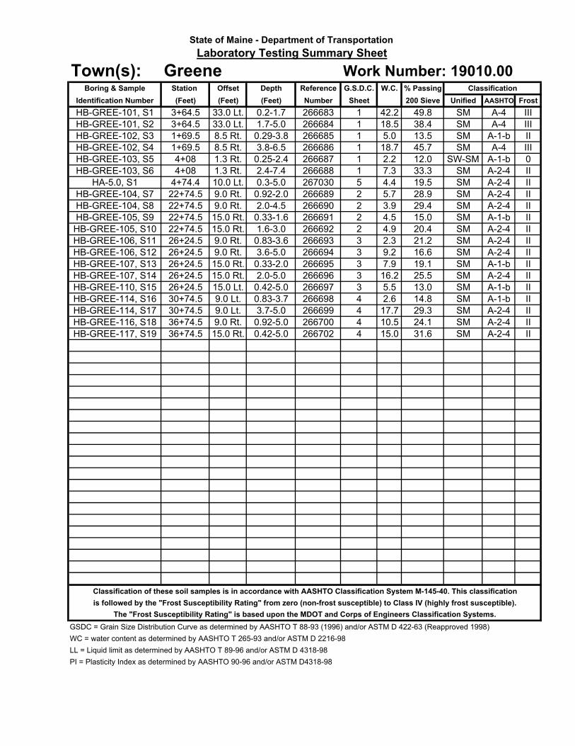
3+64.5 33.0 Lt. 0.2-1.7 266683 1 42.2 SM A-4 III
3+64.5 33.0 Lt. 1.7-5.0 266684 1 18.5 SM A-4 III
1+69.5 8.5 Rt. 0.29-3.8 266685 1 5.0 SM A-1-b II
1+69.5 8.5 Rt. 3.8-6.5 266686 1 18.7 SM A-4 III
4+08 1.3 Rt. 0.25-2.4 266687 1 2.2 SW-SM A-1-b 0
4+08 1.3 Rt. 2.4-7.4 266688 1 7.3 SM A-2-4 II
4+74.4 10.0 Lt. 0.3-5.0 267030 5 4.4 SM A-2-4 II
22+74.5 9.0 Rt. 0.92-2.0 266689 2 5.7 SM A-2-4 II
22+74.5 9.0 Rt. 2.0-4.5 266690 2 3.9 SM A-2-4 II
22+74.5 15.0 Rt. 0.33-1.6 266691 2 4.5 SM A-1-b II
22+74.5 15.0 Rt. 1.6-3.0 266692 2 4.9 SM A-2-4 II
26+24.5 9.0 Rt. 0.83-3.6 266693 3 2.3 SM A-2-4 II
26+24.5 9.0 Rt. 3.6-5.0 266694 3 9.2 SM A-2-4 II
26+24.5 15.0 Rt. 0.33-2.0 266695 3 7.9 SM A-1-b II
26+24.5 15.0 Rt. 2.0-5.0 266696 3 16.2 SM A-2-4 II
26+24.5 15.0 Lt. 0.42-5.0 266697 3 5.5 SM A-1-b II
30+74.5 9.0 Lt. 0.83-3.7 266698 4 2.6 SM A-1-b II
30+74.5 9.0 Lt. 3.7-5.0 266699 4 17.7 SM A-2-4 II
36+74.5 9.0 Rt. 0.92-5.0 266700 4 10.5 SM A-2-4 II
36+74.5 15.0 Rt. 0.42-5.0 266702 4 15.0 SM A-2-4 II
Classification of these soil samples is in accordance with AASHTO Classification System M-145-40. This classification
is followed by the "Frost Susceptibility Rating" from zero (non-frost susceptible) to Class IV (highly frost susceptible).
The "Frost Susceptibility Rating" is based upon the MDOT and Corps of Engineers Classification Systems.
GSDC = Grain Size Distribution Curve as determined by AASHTO T 88-93 (1996) and/or ASTM D 422-63 (Reapproved 1998)
WC = water content as determined by AASHTO T 265-93 and/or ASTM D 2216-98
LL = Liquid limit as determined by AASHTO T 89-96 and/or ASTM D 4318-98
PI = Plasticity Index as determined by AASHTO 90-96 and/or ASTM D4318-98
24.1
31.6
16.6
19.1
25.5
13.0
14.8
29.3
28.9
45.7
12.0
33.3
19.5
29.4
15.0
20.4
21.2
HB-GREE-117, S19
HB-GREE-110, S15
HB-GREE-114, S16
HB-GREE-114, S17
HB-GREE-116, S18
HB-GREE-106, S11
HB-GREE-106, S12
HB-GREE-107, S13
HB-GREE-107, S14
HB-GREE-104, S7
HB-GREE-104, S8
HB-GREE-105, S9
HB-GREE-105, S10
HB-GREE-103, S6
Identification Number
HB-GREE-101, S1
HB-GREE-103, S5
Work Number: 19010.00
HB-GREE-101, S2
% Passing
200 Sieve
49.8
38.4
13.5
HA-5.0, S1
Classification
State of Maine - Department of Transportation
Laboratory Testing Summary Sheet
Town(s): GreeneBoring & Sample
HB-GREE-102, S3
HB-GREE-102, S4

3"
2"1-1/2"
1"
3/4"
1/2"
3/8"
1/4"
#4
#8
#10
#16
#20
#40
#60
#100
#200
0.05
0.03
0.010
0.005
0.001
76.2
50.8
38.1
25.4
19.05
12.7
9.53
6.35
4.75
2.36
2.00
1.18
0.85
0.426
0.25
0.15
0.075
0.05
0.03
0.005
GRAVEL
SAND
SILT
SIEVE ANALYSIS
US Standard Sieve Numbers
HYDROMETER ANALYSIS
Grain Diameter, mm
State of Maine Department of Transportation
GRAIN SIZE DISTRIBUTIO
N CURVE
100
10
10.1
0.01
0.001
Grain Diameter, mm
0
10
20
30
40
50
60
70
80
90
100
Percent Finer by Weight
100
90
80
70
60
50
40
30
20
10
0
Percent Retained by Weight
CLAY
SHEET NO.
UNIFIED CLASSIFICATION
Sandy SILT, trace gravel.
Silty SAND, trace gravel.
SAND, little gravel, little silt.
Silty SAND, little gravel.
42.2
2.2
SAND, some gravel, little silt.
18.5
5.0
18.7
HB-GREE-101/S1
HB-GREE-103/S5
HB-GREE-101/S2
HB-GREE-102/S3
HB-GREE-102/S4
7.3
SAND, some silt, trace gravel.
HB-GREE-103/S6
0.2-1.7
0.25-2.4
1.7-5.0
0.29-3.8
3.8-6.5
2.4-7.4
Depth, ft
Boring/Sample No.
Description
W, %
LL
PL
PI
� ��� � ��� � ��� � ��� � ��� � ���
SHEET 1
Greene
019010.00
WHITE, TERRY A 11/26/2012
WIN
Town
Reported by/Date
33.0 LT
1.3 RT
33.0 LT
8.5 RT
8.5 RT
1.3 RT
Offset, ft
3+64.5
4+08
3+64.5
1+69.5
1+69.5
4+08
Station

3"
2"1-1/2"
1"
3/4"
1/2"
3/8"
1/4"
#4
#8
#10
#16
#20
#40
#60
#100
#200
0.05
0.03
0.010
0.005
0.001
76.2
50.8
38.1
25.4
19.05
12.7
9.53
6.35
4.75
2.36
2.00
1.18
0.85
0.426
0.25
0.15
0.075
0.05
0.03
0.005
GRAVEL
SAND
SILT
SIEVE ANALYSIS
US Standard Sieve Numbers
HYDROMETER ANALYSIS
Grain Diameter, mm
State of Maine Department of Transportation
GRAIN SIZE DISTRIBUTIO
N CURVE
100
10
10.1
0.01
0.001
Grain Diameter, mm
0
10
20
30
40
50
60
70
80
90
100
Percent Finer by Weight
100
90
80
70
60
50
40
30
20
10
0
Percent Retained by Weight
CLAY
SHEET NO.
UNIFIED CLASSIFICATION
SAND, some silt, trace gravel.
SAND, some silt, trace gravel.
SAND, little gravel, little silt.
SAND, some silt, trace gravel.
5.7
3.9
4.5
4.9
HB-GREE-104/S7
HB-GREE-104/S8
HB-GREE-105/S9
HB-G
REE-105/S10
0.92-2.0
2.0-4.5
0.33-1.6
1.6-3.0
Depth, ft
Boring/Sample No.
Description
W, %
LL
PL
PI
� ��� � ��� � ��� � ��� � ��� � ���
SHEET 2
Greene
019010.00
WHITE, TERRY A 11/26/2012
WIN
Town
Reported by/Date
9.0 RT
9.0 RT
15.0 RT
15.0 RT
Offset, ft
22+74.5
22+74.5
22+74.5
22+74.5
Station

3"
2"1-1/2"
1"
3/4"
1/2"
3/8"
1/4"
#4
#8
#10
#16
#20
#40
#60
#100
#200
0.05
0.03
0.010
0.005
0.001
76.2
50.8
38.1
25.4
19.05
12.7
9.53
6.35
4.75
2.36
2.00
1.18
0.85
0.426
0.25
0.15
0.075
0.05
0.03
0.005
GRAVEL
SAND
SILT
SIEVE ANALYSIS
US Standard Sieve Numbers
HYDROMETER ANALYSIS
Grain Diameter, mm
State of Maine Department of Transportation
GRAIN SIZE DISTRIBUTIO
N CURVE
100
10
10.1
0.01
0.001
Grain Diameter, mm
0
10
20
30
40
50
60
70
80
90
100
Percent Finer by Weight
100
90
80
70
60
50
40
30
20
10
0
Percent Retained by Weight
CLAY
SHEET NO.
UNIFIED CLASSIFICATION
SAND, some silt, little gravel.
SAND, some silt, trace gravel.
SAND, little silt, little gravel.
SAND, little gravel, little silt.
2.3
5.5
SAND, little gravel, little silt.
9.2
7.9
16.2
HB-G
REE-106/S11
HB-G
REE-110/S15
HB-G
REE-106/S12
HB-G
REE-107/S13
HB-G
REE-107/S14
0.83-3.6
0.42-5.0
3.6-5.0
0.33-2.0
2.0-5.0
Depth, ft
Boring/Sample No.
Description
W, %
LL
PL
PI
� ��� � ��� � ��� � ��� � ��� � ���
SHEET 3
Greene
019010.00
WHITE, TERRY A 11/26/2012
WIN
Town
Reported by/Date
9.0 RT
15.0 LT
9.0 RT
15.0 RT
15.0 RT
Offset, ft
26+24.5
26+24.5
26+24.5
26+24.5
26+24.5
Station

3"
2"1-1/2"
1"
3/4"
1/2"
3/8"
1/4"
#4
#8
#10
#16
#20
#40
#60
#100
#200
0.05
0.03
0.010
0.005
0.001
76.2
50.8
38.1
25.4
19.05
12.7
9.53
6.35
4.75
2.36
2.00
1.18
0.85
0.426
0.25
0.15
0.075
0.05
0.03
0.005
GRAVEL
SAND
SILT
SIEVE ANALYSIS
US Standard Sieve Numbers
HYDROMETER ANALYSIS
Grain Diameter, mm
State of Maine Department of Transportation
GRAIN SIZE DISTRIBUTIO
N CURVE
100
10
10.1
0.01
0.001
Grain Diameter, mm
0
10
20
30
40
50
60
70
80
90
100
Percent Finer by Weight
100
90
80
70
60
50
40
30
20
10
0
Percent Retained by Weight
CLAY
SHEET NO.
UNIFIED CLASSIFICATION
SAND, little silt, little gravel.
SAND, some silt, little gravel.
SAND, some silt, little gravel.
SAND, some silt, trace gravel.
2.6
17.7
10.5
15.0
HB-G
REE-114/S16
HB-G
REE-114/S17
HB-G
REE-116/S18
HB-G
REE-117/S19
0.83-3.7
3.7-5.0
0.92-5.0
0.42-5.0
Depth, ft
Boring/Sample No.
Description
W, %
LL
PL
PI
� ��� � ��� � ��� � ��� � ��� � ���
SHEET 4
Greene
019010.00
WHITE, TERRY A 11/26/2012
WIN
Town
Reported by/Date
9.0 LT
9.0 LT
9.0 RT
15.0 RT
Offset, ft
30+74.4
30+74.5
36+74.5
36+74.5
Station

3"
2"1-1/2"
1"
3/4"
1/2"
3/8"
1/4"
#4
#8
#10
#16
#20
#40
#60
#100
#200
0.05
0.03
0.010
0.005
0.001
76.2
50.8
38.1
25.4
19.05
12.7
9.53
6.35
4.75
2.36
2.00
1.18
0.85
0.426
0.25
0.15
0.075
0.05
0.03
0.005
GRAVEL
SAND
SILT
SIEVE ANALYSIS
US Standard Sieve Numbers
HYDROMETER ANALYSIS
Grain Diameter, mm
State of Maine Department of Transportation
GRAIN SIZE DISTRIBUTIO
N CURVE
100
10
10.1
0.01
0.001
Grain Diameter, mm
0
10
20
30
40
50
60
70
80
90
100
Percent Finer by Weight
100
90
80
70
60
50
40
30
20
10
0
Percent Retained by Weight
CLAY
SHEET NO.
UNIFIED CLASSIFICATION
SAND, some gravel, little silt.
4.4
HA-5.0/S1
0.3-5.0
Depth, ft
Boring/Sample No.
Description
W, %
LL
PL
PI
� ��� � ��� � ��� � ��� � ��� � ���
SHEET 5
Greene
019010.00
WHITE, TERRY A 12/5/2012
WIN
Town
Reported by/Date
10.0 LT
Offset, ft
4+74.4
Station

0
5
10
15
20
25
S1
S2
0.20 - 1.70
1.70 - 5.00
SSA-0.20
-1.70
-5.00
TOPSOIL.0.20
Dark brown, moist, fine to medium sandy SILT, little organics, roots.
1.70Light brown, wet, fine to medium SAND, little silt.
5.00Bottom of Exploration at 5.00 feet below ground surface.
NO REFUSAL
G#266683
A-4, SM
WC=42.2%
G#266684
A-4, SM
WC=18.5%
Maine Department of Transportation Project: Meadow Hill Rd., West Maine St. and Route
11/202
Boring No.: HB-GREE-101
Soil/Rock Exploration LogLocation: Greene, Maine
US CUSTOMARY UNITS WIN: 19010.00
Driller: MaineDOT Elevation (ft.) Auger ID/OD: 5" Dia.
Operator: Enos/Giles/Daggett Datum: NAVD88 Sampler: Off Flights
Logged By: B. Wilder Rig Type: CME 45C Hammer Wt./Fall: N/A
Date Start/Finish: 10/31/12-10/31/12 Drilling Method: Soild Stem Auger Core Barrel: N/A
Boring Location: 3+64.5, 33.0 ft Lt. Casing ID/OD: N/A Water Level*: None Observed
Definitions: Definitions: Definitions:
D = Split Spoon Sample Su = Insitu Field Vane Shear Strength (psf) WC = water content, percent
MD = Unsuccessful Split Spoon Sample attempt Tv = Pocket Torvane Shear Strength (psf) LL = Liquid Limit
U = Thin Wall Tube Sample qp = Unconfined Compressive Strength (ksf) PL = Plastic Limit
R = Rock Core Sample Su(lab) = Lab Vane Shear Strength (psf) PI = Plasticity Index
V = Insitu Vane Shear Test WOH = weight of 140lb. hammer G = Grain Size AnalysisSSA = Solid Stem Auger WOR = weight of rods WOC = weight of casing C = Consolidation Test
Remarks:
Meadow Hill Road
Stratification lines represent approximate boundaries between soil types; transitions may be gradual.
* Water level readings have been made at times and under conditions stated. Groundwater fluctuations may occur due to conditions otherthan those present at the time measurements were made. Boring No.: HB-GREE-101
Depth
(ft
.)
Sam
ple
No.
Sample Information
Pen./
Rec.
(in.)
Sam
ple
Depth
(ft.
)
Blo
ws (
/6 in.)
Shear
Str
ength
(psf)
or
RQ
D (
%)
N-v
alu
e
Casin
g
Blo
ws
Ele
vation
(ft.
)
Gra
phic
Log
Visual Description and Remarks
LaboratoryTesting Results/
AASHTO and
Unified Class.
Page 1 of 1
0
5
10
15
20
25
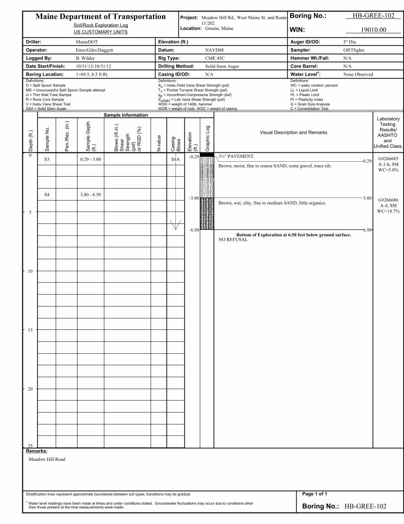
S3
S4
0.29 - 3.80
3.80 - 6.50
SSA-0.29
-3.80
-6.50
3½" PAVEMENT.0.29
Brown, moist, fine to coarse SAND, some gravel, trace silt.
3.80Brown, wet, silty, fine to medium SAND, little organics.
6.50Bottom of Exploration at 6.50 feet below ground surface.
NO REFUSAL
G#266685
A-1-b, SM
WC=5.0%
G#266686
A-4, SM
WC=18.7%
Maine Department of Transportation Project: Meadow Hill Rd., West Maine St. and Route
11/202
Boring No.: HB-GREE-102
Soil/Rock Exploration LogLocation: Greene, Maine
US CUSTOMARY UNITS WIN: 19010.00
Driller: MaineDOT Elevation (ft.) Auger ID/OD: 5" Dia.
Operator: Enos/Giles/Daggett Datum: NAVD88 Sampler: Off Flights
Logged By: B. Wilder Rig Type: CME 45C Hammer Wt./Fall: N/A
Date Start/Finish: 10/31/12-10/31/12 Drilling Method: Soild Stem Auger Core Barrel: N/A
Boring Location: 1+69.5, 8.5 ft Rt. Casing ID/OD: N/A Water Level*: None Observed
Definitions: Definitions: Definitions:
D = Split Spoon Sample Su = Insitu Field Vane Shear Strength (psf) WC = water content, percent
MD = Unsuccessful Split Spoon Sample attempt Tv = Pocket Torvane Shear Strength (psf) LL = Liquid Limit
U = Thin Wall Tube Sample qp = Unconfined Compressive Strength (ksf) PL = Plastic Limit
R = Rock Core Sample Su(lab) = Lab Vane Shear Strength (psf) PI = Plasticity Index
V = Insitu Vane Shear Test WOH = weight of 140lb. hammer G = Grain Size AnalysisSSA = Solid Stem Auger WOR = weight of rods WOC = weight of casing C = Consolidation Test
Remarks:
Meadow Hill Road
Stratification lines represent approximate boundaries between soil types; transitions may be gradual.
* Water level readings have been made at times and under conditions stated. Groundwater fluctuations may occur due to conditions otherthan those present at the time measurements were made. Boring No.: HB-GREE-102
Depth
(ft
.)
Sam
ple
No.
Sample Information
Pen./
Rec.
(in.)
Sam
ple
Depth
(ft.
)
Blo
ws (
/6 in.)
Shear
Str
ength
(psf)
or
RQ
D (
%)
N-v
alu
e
Casin
g
Blo
ws
Ele
vation
(ft.
)
Gra
phic
Log
Visual Description and Remarks
LaboratoryTesting Results/
AASHTO and
Unified Class.
Page 1 of 1

0
5
10
15
20
25
S5
S6
0.25 - 2.40
2.40 - 7.40
SSA-0.25
-2.40
-7.40
3" PAVEMENT.0.25
Brown, damp, fine to coarse SAND, some gravel, trace silt.
2.40Light brown, damp, fine to coarse SAND, some silt, occasional cobbles.
7.40Bottom of Exploration at 7.40 feet below ground surface.
REFUSAL
G#266687
A-1-b, SW-SM
WC=2.2%
G#266688
A-2-4, SM
WC=7.3%
Maine Department of Transportation Project: Meadow Hill Rd., West Maine St. and Route
11/202
Boring No.: HB-GREE-103
Soil/Rock Exploration LogLocation: Greene, Maine
US CUSTOMARY UNITS WIN: 19010.00
Driller: MaineDOT Elevation (ft.) Auger ID/OD: 5" Dia.
Operator: Enos/Giles/Daggett Datum: NAVD88 Sampler: Off Flights
Logged By: B. Wilder Rig Type: CME 45C Hammer Wt./Fall: N/A
Date Start/Finish: 10/31/12-10/31/12 Drilling Method: Soild Stem Auger Core Barrel: N/A
Boring Location: 4+08, 1.3 ft Rt. Casing ID/OD: N/A Water Level*: None Observed
Definitions: Definitions: Definitions:
D = Split Spoon Sample Su = Insitu Field Vane Shear Strength (psf) WC = water content, percent
MD = Unsuccessful Split Spoon Sample attempt Tv = Pocket Torvane Shear Strength (psf) LL = Liquid Limit
U = Thin Wall Tube Sample qp = Unconfined Compressive Strength (ksf) PL = Plastic Limit
R = Rock Core Sample Su(lab) = Lab Vane Shear Strength (psf) PI = Plasticity Index
V = Insitu Vane Shear Test WOH = weight of 140lb. hammer G = Grain Size AnalysisSSA = Solid Stem Auger WOR = weight of rods WOC = weight of casing C = Consolidation Test
Remarks:
West Main Street
Stratification lines represent approximate boundaries between soil types; transitions may be gradual.
* Water level readings have been made at times and under conditions stated. Groundwater fluctuations may occur due to conditions otherthan those present at the time measurements were made. Boring No.: HB-GREE-103
Depth
(ft
.)
Sam
ple
No.
Sample Information
Pen./
Rec.
(in.)
Sam
ple
Depth
(ft.
)
Blo
ws (
/6 in.)
Shear
Str
ength
(psf)
or
RQ
D (
%)
N-v
alu
e
Casin
g
Blo
ws
Ele
vation
(ft.
)
Gra
phic
Log
Visual Description and Remarks
LaboratoryTesting Results/
AASHTO and
Unified Class.
Page 1 of 1
0
5
10
15
20
25
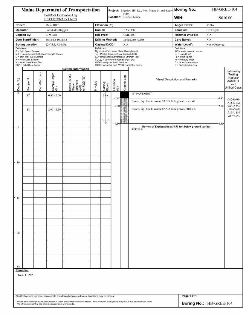
S7
S8
0.92 - 2.00
2.00 - 4.50
SSA-0.92
-2.00
-4.50
11" PAVEMENT.
0.92Brown, dry, fine to coarse SAND, little gravel, trace silt.
2.00Brown, dry, fine to coarse SAND, little gravel, little silt.
4.50Bottom of Exploration at 4.50 feet below ground surface.
REFUSAL
G#266689
A-2-4, SM
WC=5.7%G#266690
A-2-4, SM
WC=3.9%
Maine Department of Transportation Project: Meadow Hill Rd., West Maine St. and Route
11/202
Boring No.: HB-GREE-104
Soil/Rock Exploration LogLocation: Greene, Maine
US CUSTOMARY UNITS WIN: 19010.00
Driller: MaineDOT Elevation (ft.) Auger ID/OD: 5" Dia.
Operator: Enos/Giles/Daggett Datum: NAVD88 Sampler: Off Flights
Logged By: B. Wilder Rig Type: CME 45C Hammer Wt./Fall: N/A
Date Start/Finish: 10/31/12-10/31/12 Drilling Method: Soild Stem Auger Core Barrel: N/A
Boring Location: 22+74.5, 9.0 ft Rt. Casing ID/OD: N/A Water Level*: None Observed
Definitions: Definitions: Definitions:
D = Split Spoon Sample Su = Insitu Field Vane Shear Strength (psf) WC = water content, percent
MD = Unsuccessful Split Spoon Sample attempt Tv = Pocket Torvane Shear Strength (psf) LL = Liquid Limit
U = Thin Wall Tube Sample qp = Unconfined Compressive Strength (ksf) PL = Plastic Limit
R = Rock Core Sample Su(lab) = Lab Vane Shear Strength (psf) PI = Plasticity Index
V = Insitu Vane Shear Test WOH = weight of 140lb. hammer G = Grain Size AnalysisSSA = Solid Stem Auger WOR = weight of rods WOC = weight of casing C = Consolidation Test
Remarks:
Route 11/202
Stratification lines represent approximate boundaries between soil types; transitions may be gradual.
* Water level readings have been made at times and under conditions stated. Groundwater fluctuations may occur due to conditions otherthan those present at the time measurements were made. Boring No.: HB-GREE-104
Depth
(ft
.)
Sam
ple
No.
Sample Information
Pen./
Rec.
(in.)
Sam
ple
Depth
(ft.
)
Blo
ws (
/6 in.)
Shear
Str
ength
(psf)
or
RQ
D (
%)
N-v
alu
e
Casin
g
Blo
ws
Ele
vation
(ft.
)
Gra
phic
Log
Visual Description and Remarks
LaboratoryTesting Results/
AASHTO and
Unified Class.
Page 1 of 1

0
5
10
15
20
25
S9
S10
0.33 - 1.60
1.60 - 3.00
SSA -0.33
-1.60
-3.00
4" PAVEMENT.0.33
Brown, damp, fine to coarse SAND, some gravel, trace silt.
1.60Light brown, damp, fine to coarse SAND, little gravel, little silt.
3.00Bottom of Exploration at 3.00 feet below ground surface.
REFUSAL
G#266691
A-1-b, SM
WC=4.5%G#266692
A-2-4, SM
WC=4.9%
Maine Department of Transportation Project: Meadow Hill Rd., West Maine St. and Route
11/202
Boring No.: HB-GREE-105
Soil/Rock Exploration LogLocation: Greene, Maine
US CUSTOMARY UNITS WIN: 19010.00
Driller: MaineDOT Elevation (ft.) Auger ID/OD: 5" Dia.
Operator: Enos/Giles/Daggett Datum: NAVD88 Sampler: Off Flights
Logged By: B. Wilder Rig Type: CME 45C Hammer Wt./Fall: N/A
Date Start/Finish: 10/31/12-10/31/12 Drilling Method: Soild Stem Auger Core Barrel: N/A
Boring Location: 22+74.5, 15.0 ft Rt. Casing ID/OD: N/A Water Level*: None Observed
Definitions: Definitions: Definitions:
D = Split Spoon Sample Su = Insitu Field Vane Shear Strength (psf) WC = water content, percent
MD = Unsuccessful Split Spoon Sample attempt Tv = Pocket Torvane Shear Strength (psf) LL = Liquid Limit
U = Thin Wall Tube Sample qp = Unconfined Compressive Strength (ksf) PL = Plastic Limit
R = Rock Core Sample Su(lab) = Lab Vane Shear Strength (psf) PI = Plasticity Index
V = Insitu Vane Shear Test WOH = weight of 140lb. hammer G = Grain Size AnalysisSSA = Solid Stem Auger WOR = weight of rods WOC = weight of casing C = Consolidation Test
Remarks:
Route 11/202
Stratification lines represent approximate boundaries between soil types; transitions may be gradual.
* Water level readings have been made at times and under conditions stated. Groundwater fluctuations may occur due to conditions otherthan those present at the time measurements were made. Boring No.: HB-GREE-105
Depth
(ft
.)
Sam
ple
No.
Sample Information
Pen./
Rec.
(in.)
Sam
ple
Depth
(ft.
)
Blo
ws (
/6 in.)
Shear
Str
ength
(psf)
or
RQ
D (
%)
N-v
alu
e
Casin
g
Blo
ws
Ele
vation
(ft.
)
Gra
phic
Log
Visual Description and Remarks
LaboratoryTesting Results/
AASHTO and
Unified Class.
Page 1 of 1

0
5
10
15
20
25
S11
S12
0.83 - 3.60
3.60 - 5.00
SSA-0.83
-3.60
-5.00
10" PAVEMENT.
0.83Brown, dry, fine to coarse SAND, some gravel, trace silt.
3.60Brown, moist, fine to coarse SAND, little gravel, little silt, occasional cobble.
5.00Bottom of Exploration at 5.00 feet below ground surface.
NO REFUSAL
G#266693
A-2-4, SM
WC=2.3%
G#266694
A-2-4, SM
WC=9.2%
Maine Department of Transportation Project: Meadow Hill Rd., West Maine St. and Route
11/202
Boring No.: HB-GREE-106
Soil/Rock Exploration LogLocation: Greene, Maine
US CUSTOMARY UNITS WIN: 19010.00
Driller: MaineDOT Elevation (ft.) Auger ID/OD: 5" Dia.
Operator: Enos/Giles/Daggett Datum: NAVD88 Sampler: Off Flights
Logged By: B. Wilder Rig Type: CME 45C Hammer Wt./Fall: N/A
Date Start/Finish: 10/31/12-10/31/12 Drilling Method: Soild Stem Auger Core Barrel: N/A
Boring Location: 26+24.5, 9.0 ft Rt. Casing ID/OD: N/A Water Level*: None Observed
Definitions: Definitions: Definitions:
D = Split Spoon Sample Su = Insitu Field Vane Shear Strength (psf) WC = water content, percent
MD = Unsuccessful Split Spoon Sample attempt Tv = Pocket Torvane Shear Strength (psf) LL = Liquid Limit
U = Thin Wall Tube Sample qp = Unconfined Compressive Strength (ksf) PL = Plastic Limit
R = Rock Core Sample Su(lab) = Lab Vane Shear Strength (psf) PI = Plasticity Index
V = Insitu Vane Shear Test WOH = weight of 140lb. hammer G = Grain Size AnalysisSSA = Solid Stem Auger WOR = weight of rods WOC = weight of casing C = Consolidation Test
Remarks:
Route 11/202
Stratification lines represent approximate boundaries between soil types; transitions may be gradual.
* Water level readings have been made at times and under conditions stated. Groundwater fluctuations may occur due to conditions otherthan those present at the time measurements were made. Boring No.: HB-GREE-106
Depth
(ft
.)
Sam
ple
No.
Sample Information
Pen./
Rec.
(in.)
Sam
ple
Depth
(ft.
)
Blo
ws (
/6 in.)
Shear
Str
ength
(psf)
or
RQ
D (
%)
N-v
alu
e
Casin
g
Blo
ws
Ele
vation
(ft.
)
Gra
phic
Log
Visual Description and Remarks
LaboratoryTesting Results/
AASHTO and
Unified Class.
Page 1 of 1

0
5
10
15
20
25
S13
S14
0.33 - 2.00
2.00 - 5.00
SSA -0.33
-2.00
-5.00
4" PAVEMENT.0.33
Brown, moist, fine to coarse SAND, some gravel, little silt.
2.00Light brown, wet, fine to coarse SAND, some silt, little gravel.
5.00Bottom of Exploration at 5.00 feet below ground surface.
NO REFUSAL
G#266695
A-1-b, SM
WC=7.9%
G#266696
A-2-4, SM
WC=16.2%
Maine Department of Transportation Project: Meadow Hill Rd., West Maine St. and Route
11/202
Boring No.: HB-GREE-107
Soil/Rock Exploration LogLocation: Greene, Maine
US CUSTOMARY UNITS WIN: 19010.00
Driller: MaineDOT Elevation (ft.) Auger ID/OD: 5" Dia.
Operator: Enos/Giles/Daggett Datum: NAVD88 Sampler: Off Flights
Logged By: B. Wilder Rig Type: CME 45C Hammer Wt./Fall: N/A
Date Start/Finish: 10/31/12-10/31/12 Drilling Method: Soild Stem Auger Core Barrel: N/A
Boring Location: 26+24.5, 15.0 ft Rt. Casing ID/OD: N/A Water Level*: None Observed
Definitions: Definitions: Definitions:
D = Split Spoon Sample Su = Insitu Field Vane Shear Strength (psf) WC = water content, percent
MD = Unsuccessful Split Spoon Sample attempt Tv = Pocket Torvane Shear Strength (psf) LL = Liquid Limit
U = Thin Wall Tube Sample qp = Unconfined Compressive Strength (ksf) PL = Plastic Limit
R = Rock Core Sample Su(lab) = Lab Vane Shear Strength (psf) PI = Plasticity Index
V = Insitu Vane Shear Test WOH = weight of 140lb. hammer G = Grain Size AnalysisSSA = Solid Stem Auger WOR = weight of rods WOC = weight of casing C = Consolidation Test
Remarks:
Route 11/202
Stratification lines represent approximate boundaries between soil types; transitions may be gradual.
* Water level readings have been made at times and under conditions stated. Groundwater fluctuations may occur due to conditions otherthan those present at the time measurements were made. Boring No.: HB-GREE-107
Depth
(ft
.)
Sam
ple
No.
Sample Information
Pen./
Rec.
(in.)
Sam
ple
Depth
(ft.
)
Blo
ws (
/6 in.)
Shear
Str
ength
(psf)
or
RQ
D (
%)
N-v
alu
e
Casin
g
Blo
ws
Ele
vation
(ft.
)
Gra
phic
Log
Visual Description and Remarks
LaboratoryTesting Results/
AASHTO and
Unified Class.
Page 1 of 1

0
5
10
15
20
25
SSA
-1.70
-5.00
Brown, moist, fine to coarse SAND, some gravel, little silt. ≅S13
1.70Light brown, wet, fine to coarse SAND, some silt, little gravel. ≅S14
5.00Bottom of Exploration at 5.00 feet below ground surface.
NO REFUSAL
Maine Department of Transportation Project: Meadow Hill Rd., West Maine St. and Route
11/202
Boring No.: HB-GREE-108
Soil/Rock Exploration LogLocation: Greene, Maine
US CUSTOMARY UNITS WIN: 19010.00
Driller: MaineDOT Elevation (ft.) Auger ID/OD: 5" Dia.
Operator: Enos/Giles/Daggett Datum: NAVD88 Sampler: Off Flights
Logged By: B. Wilder Rig Type: CME 45C Hammer Wt./Fall: N/A
Date Start/Finish: 10/31/12-10/31/12 Drilling Method: Soild Stem Auger Core Barrel: N/A
Boring Location: 26+24.5, 20.0 ft Rt. Casing ID/OD: N/A Water Level*: None Observed
Definitions: Definitions: Definitions:
D = Split Spoon Sample Su = Insitu Field Vane Shear Strength (psf) WC = water content, percent
MD = Unsuccessful Split Spoon Sample attempt Tv = Pocket Torvane Shear Strength (psf) LL = Liquid Limit
U = Thin Wall Tube Sample qp = Unconfined Compressive Strength (ksf) PL = Plastic Limit
R = Rock Core Sample Su(lab) = Lab Vane Shear Strength (psf) PI = Plasticity Index
V = Insitu Vane Shear Test WOH = weight of 140lb. hammer G = Grain Size AnalysisSSA = Solid Stem Auger WOR = weight of rods WOC = weight of casing C = Consolidation Test
Remarks:
Route 11/202
Stratification lines represent approximate boundaries between soil types; transitions may be gradual.
* Water level readings have been made at times and under conditions stated. Groundwater fluctuations may occur due to conditions otherthan those present at the time measurements were made. Boring No.: HB-GREE-108
Depth
(ft
.)
Sam
ple
No.
Sample Information
Pen./
Rec.
(in.)
Sam
ple
Depth
(ft.
)
Blo
ws (
/6 in.)
Shear
Str
ength
(psf)
or
RQ
D (
%)
N-v
alu
e
Casin
g
Blo
ws
Ele
vation
(ft.
)
Gra
phic
Log
Visual Description and Remarks
LaboratoryTesting Results/
AASHTO and
Unified Class.
Page 1 of 1

0
5
10
15
20
25
SSA -0.58-0.83
-3.70
-5.00
7" PAVEMENT.0.58
3" Unbound Pavement.0.83
Brown, dry, fine to coarse SAND, some gravel, trace silt. ≅S11
3.70Brown, moist, fine to coarse SAND, little gravel, little silt, occasional cobble.
≅S125.00
Bottom of Exploration at 5.00 feet below ground surface.NO REFUSAL
Maine Department of Transportation Project: Meadow Hill Rd., West Maine St. and Route
11/202
Boring No.: HB-GREE-109
Soil/Rock Exploration LogLocation: Greene, Maine
US CUSTOMARY UNITS WIN: 19010.00
Driller: MaineDOT Elevation (ft.) Auger ID/OD: 5" Dia.
Operator: Enos/Giles/Daggett Datum: NAVD88 Sampler: Off Flights
Logged By: B. Wilder Rig Type: CME 45C Hammer Wt./Fall: N/A
Date Start/Finish: 10/31/12-10/31/12 Drilling Method: Soild Stem Auger Core Barrel: N/A
Boring Location: 26+24.5, 10.0 ft Lt. Casing ID/OD: N/A Water Level*: None Observed
Definitions: Definitions: Definitions:
D = Split Spoon Sample Su = Insitu Field Vane Shear Strength (psf) WC = water content, percent
MD = Unsuccessful Split Spoon Sample attempt Tv = Pocket Torvane Shear Strength (psf) LL = Liquid Limit
U = Thin Wall Tube Sample qp = Unconfined Compressive Strength (ksf) PL = Plastic Limit
R = Rock Core Sample Su(lab) = Lab Vane Shear Strength (psf) PI = Plasticity Index
V = Insitu Vane Shear Test WOH = weight of 140lb. hammer G = Grain Size AnalysisSSA = Solid Stem Auger WOR = weight of rods WOC = weight of casing C = Consolidation Test
Remarks:
Route 11/202
Stratification lines represent approximate boundaries between soil types; transitions may be gradual.
* Water level readings have been made at times and under conditions stated. Groundwater fluctuations may occur due to conditions otherthan those present at the time measurements were made. Boring No.: HB-GREE-109
Depth
(ft
.)
Sam
ple
No.
Sample Information
Pen./
Rec.
(in.)
Sam
ple
Depth
(ft.
)
Blo
ws (
/6 in.)
Shear
Str
ength
(psf)
or
RQ
D (
%)
N-v
alu
e
Casin
g
Blo
ws
Ele
vation
(ft.
)
Gra
phic
Log
Visual Description and Remarks
LaboratoryTesting Results/
AASHTO and
Unified Class.
Page 1 of 1
0
5
10
15
20
25
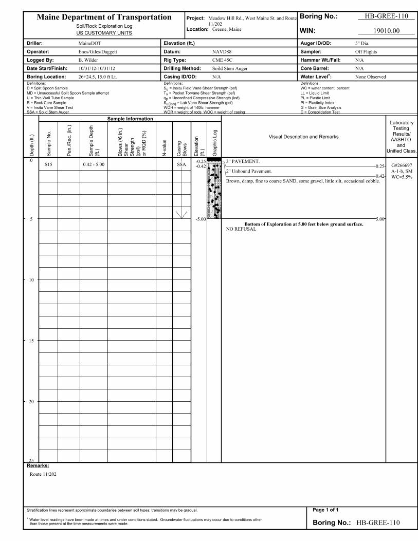
S15 0.42 - 5.00 SSA-0.25-0.42
-5.00
3" PAVEMENT.0.25
2" Unbound Pavement.0.42
Brown, damp, fine to coarse SAND, some gravel, little silt, occasional cobble.
5.00Bottom of Exploration at 5.00 feet below ground surface.
NO REFUSAL
G#266697
A-1-b, SM
WC=5.5%
Maine Department of Transportation Project: Meadow Hill Rd., West Maine St. and Route
11/202
Boring No.: HB-GREE-110
Soil/Rock Exploration LogLocation: Greene, Maine
US CUSTOMARY UNITS WIN: 19010.00
Driller: MaineDOT Elevation (ft.) Auger ID/OD: 5" Dia.
Operator: Enos/Giles/Daggett Datum: NAVD88 Sampler: Off Flights
Logged By: B. Wilder Rig Type: CME 45C Hammer Wt./Fall: N/A
Date Start/Finish: 10/31/12-10/31/12 Drilling Method: Soild Stem Auger Core Barrel: N/A
Boring Location: 26+24.5, 15.0 ft Lt. Casing ID/OD: N/A Water Level*: None Observed
Definitions: Definitions: Definitions:
D = Split Spoon Sample Su = Insitu Field Vane Shear Strength (psf) WC = water content, percent
MD = Unsuccessful Split Spoon Sample attempt Tv = Pocket Torvane Shear Strength (psf) LL = Liquid Limit
U = Thin Wall Tube Sample qp = Unconfined Compressive Strength (ksf) PL = Plastic Limit
R = Rock Core Sample Su(lab) = Lab Vane Shear Strength (psf) PI = Plasticity Index
V = Insitu Vane Shear Test WOH = weight of 140lb. hammer G = Grain Size AnalysisSSA = Solid Stem Auger WOR = weight of rods WOC = weight of casing C = Consolidation Test
Remarks:
Route 11/202
Stratification lines represent approximate boundaries between soil types; transitions may be gradual.
* Water level readings have been made at times and under conditions stated. Groundwater fluctuations may occur due to conditions otherthan those present at the time measurements were made. Boring No.: HB-GREE-110
Depth
(ft
.)
Sam
ple
No.
Sample Information
Pen./
Rec.
(in.)
Sam
ple
Depth
(ft.
)
Blo
ws (
/6 in.)
Shear
Str
ength
(psf)
or
RQ
D (
%)
N-v
alu
e
Casin
g
Blo
ws
Ele
vation
(ft.
)
Gra
phic
Log
Visual Description and Remarks
LaboratoryTesting Results/
AASHTO and
Unified Class.
Page 1 of 1
0
5
10
15
20
25
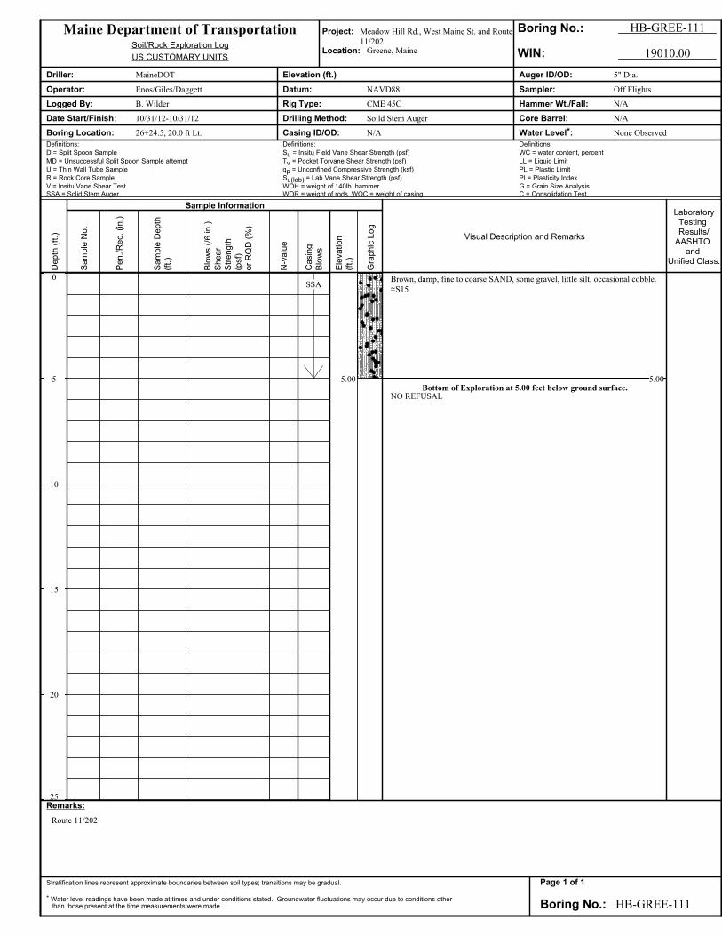
SSA
-5.00
Brown, damp, fine to coarse SAND, some gravel, little silt, occasional cobble.
≅S15
5.00Bottom of Exploration at 5.00 feet below ground surface.
NO REFUSAL
Maine Department of Transportation Project: Meadow Hill Rd., West Maine St. and Route
11/202
Boring No.: HB-GREE-111
Soil/Rock Exploration LogLocation: Greene, Maine
US CUSTOMARY UNITS WIN: 19010.00
Driller: MaineDOT Elevation (ft.) Auger ID/OD: 5" Dia.
Operator: Enos/Giles/Daggett Datum: NAVD88 Sampler: Off Flights
Logged By: B. Wilder Rig Type: CME 45C Hammer Wt./Fall: N/A
Date Start/Finish: 10/31/12-10/31/12 Drilling Method: Soild Stem Auger Core Barrel: N/A
Boring Location: 26+24.5, 20.0 ft Lt. Casing ID/OD: N/A Water Level*: None Observed
Definitions: Definitions: Definitions:
D = Split Spoon Sample Su = Insitu Field Vane Shear Strength (psf) WC = water content, percent
MD = Unsuccessful Split Spoon Sample attempt Tv = Pocket Torvane Shear Strength (psf) LL = Liquid Limit
U = Thin Wall Tube Sample qp = Unconfined Compressive Strength (ksf) PL = Plastic Limit
R = Rock Core Sample Su(lab) = Lab Vane Shear Strength (psf) PI = Plasticity Index
V = Insitu Vane Shear Test WOH = weight of 140lb. hammer G = Grain Size AnalysisSSA = Solid Stem Auger WOR = weight of rods WOC = weight of casing C = Consolidation Test
Remarks:
Route 11/202
Stratification lines represent approximate boundaries between soil types; transitions may be gradual.
* Water level readings have been made at times and under conditions stated. Groundwater fluctuations may occur due to conditions otherthan those present at the time measurements were made. Boring No.: HB-GREE-111
Depth
(ft
.)
Sam
ple
No.
Sample Information
Pen./
Rec.
(in.)
Sam
ple
Depth
(ft.
)
Blo
ws (
/6 in.)
Shear
Str
ength
(psf)
or
RQ
D (
%)
N-v
alu
e
Casin
g
Blo
ws
Ele
vation
(ft.
)
Gra
phic
Log
Visual Description and Remarks
LaboratoryTesting Results/
AASHTO and
Unified Class.
Page 1 of 1

0
5
10
15
20
25
SSA-0.88
-2.20
-4.90
10½" PAVEMENT.
0.88Brown, dry, fine to coarse SAND, little gravel, trace silt. ≅S7
2.20Brown, dry, fine to coarse SAND, little gravel, little silt. ≅S8
4.90Bottom of Exploration at 4.90 feet below ground surface.
REFUSAL
Maine Department of Transportation Project: Meadow Hill Rd., West Maine St. and Route
11/202
Boring No.: HB-GREE-112
Soil/Rock Exploration LogLocation: Greene, Maine
US CUSTOMARY UNITS WIN: 19010.00
Driller: MaineDOT Elevation (ft.) Auger ID/OD: 5" Dia.
Operator: Enos/Giles/Daggett Datum: NAVD88 Sampler: Off Flights
Logged By: B. Wilder Rig Type: CME 45C Hammer Wt./Fall: N/A
Date Start/Finish: 10/31/12-10/31/12 Drilling Method: Soild Stem Auger Core Barrel: N/A
Boring Location: 22+74.5, 9.0 ft Lt. Casing ID/OD: N/A Water Level*: None Observed
Definitions: Definitions: Definitions:
D = Split Spoon Sample Su = Insitu Field Vane Shear Strength (psf) WC = water content, percent
MD = Unsuccessful Split Spoon Sample attempt Tv = Pocket Torvane Shear Strength (psf) LL = Liquid Limit
U = Thin Wall Tube Sample qp = Unconfined Compressive Strength (ksf) PL = Plastic Limit
R = Rock Core Sample Su(lab) = Lab Vane Shear Strength (psf) PI = Plasticity Index
V = Insitu Vane Shear Test WOH = weight of 140lb. hammer G = Grain Size AnalysisSSA = Solid Stem Auger WOR = weight of rods WOC = weight of casing C = Consolidation Test
Remarks:
Route 11/202
Stratification lines represent approximate boundaries between soil types; transitions may be gradual.
* Water level readings have been made at times and under conditions stated. Groundwater fluctuations may occur due to conditions otherthan those present at the time measurements were made. Boring No.: HB-GREE-112
Depth
(ft
.)
Sam
ple
No.
Sample Information
Pen./
Rec.
(in.)
Sam
ple
Depth
(ft.
)
Blo
ws (
/6 in.)
Shear
Str
ength
(psf)
or
RQ
D (
%)
N-v
alu
e
Casin
g
Blo
ws
Ele
vation
(ft.
)
Gra
phic
Log
Visual Description and Remarks
LaboratoryTesting Results/
AASHTO and
Unified Class.
Page 1 of 1

0
5
10
15
20
25
SSA -0.33
-1.50
-4.80
4" PAVEMENT.0.33
Brown, damp, fine to coarse SAND, some gravel, trace silt. ≅S91.50
Light brown, damp, fine to coarse SAND, little gravel, little silt. ≅S10
4.80Bottom of Exploration at 4.80 feet below ground surface.
REFUSAL
Maine Department of Transportation Project: Meadow Hill Rd., West Maine St. and Route
11/202
Boring No.: HB-GREE-113
Soil/Rock Exploration LogLocation: Greene, Maine
US CUSTOMARY UNITS WIN: 19010.00
Driller: MaineDOT Elevation (ft.) Auger ID/OD: 5" Dia.
Operator: Enos/Giles/Daggett Datum: NAVD88 Sampler: Off Flights
Logged By: B. Wilder Rig Type: CME 45C Hammer Wt./Fall: N/A
Date Start/Finish: 10/31/12-10/31/12 Drilling Method: Soild Stem Auger Core Barrel: N/A
Boring Location: 22+74.5, 15.0 ft Lt. Casing ID/OD: N/A Water Level*: None Observed
Definitions: Definitions: Definitions:
D = Split Spoon Sample Su = Insitu Field Vane Shear Strength (psf) WC = water content, percent
MD = Unsuccessful Split Spoon Sample attempt Tv = Pocket Torvane Shear Strength (psf) LL = Liquid Limit
U = Thin Wall Tube Sample qp = Unconfined Compressive Strength (ksf) PL = Plastic Limit
R = Rock Core Sample Su(lab) = Lab Vane Shear Strength (psf) PI = Plasticity Index
V = Insitu Vane Shear Test WOH = weight of 140lb. hammer G = Grain Size AnalysisSSA = Solid Stem Auger WOR = weight of rods WOC = weight of casing C = Consolidation Test
Remarks:
Route 11/202
Stratification lines represent approximate boundaries between soil types; transitions may be gradual.
* Water level readings have been made at times and under conditions stated. Groundwater fluctuations may occur due to conditions otherthan those present at the time measurements were made. Boring No.: HB-GREE-113
Depth
(ft
.)
Sam
ple
No.
Sample Information
Pen./
Rec.
(in.)
Sam
ple
Depth
(ft.
)
Blo
ws (
/6 in.)
Shear
Str
ength
(psf)
or
RQ
D (
%)
N-v
alu
e
Casin
g
Blo
ws
Ele
vation
(ft.
)
Gra
phic
Log
Visual Description and Remarks
LaboratoryTesting Results/
AASHTO and
Unified Class.
Page 1 of 1

0
5
10
15
20
25
S16
S17
0.83 - 3.70
3.70 - 5.00
SSA-0.83
-3.70
-5.00
10" PAVEMENT.
0.83Brown, dry, fine to coarse SAND, some gravel, trace silt, occasional cobble.
3.70Brown, moist, fine to coarse SAND, some silt, little gravel.
5.00Bottom of Exploration at 5.00 feet below ground surface.
NO REFUSAL
G#266698
A-1-b, SM
WC=2.6%
G#266699
A-2-4, SM
WC=17.7%
Maine Department of Transportation Project: Meadow Hill Rd., West Maine St. and Route
11/202
Boring No.: HB-GREE-114
Soil/Rock Exploration LogLocation: Greene, Maine
US CUSTOMARY UNITS WIN: 19010.00
Driller: MaineDOT Elevation (ft.) Auger ID/OD: 5" Dia.
Operator: Enos/Giles/Daggett Datum: NAVD88 Sampler: Off Flights
Logged By: B. Wilder Rig Type: CME 45C Hammer Wt./Fall: N/A
Date Start/Finish: 10/31/12-10/31/12 Drilling Method: Soild Stem Auger Core Barrel: N/A
Boring Location: 30+74.5, 9.0 ft Lt. Casing ID/OD: N/A Water Level*: None Observed
Definitions: Definitions: Definitions:
D = Split Spoon Sample Su = Insitu Field Vane Shear Strength (psf) WC = water content, percent
MD = Unsuccessful Split Spoon Sample attempt Tv = Pocket Torvane Shear Strength (psf) LL = Liquid Limit
U = Thin Wall Tube Sample qp = Unconfined Compressive Strength (ksf) PL = Plastic Limit
R = Rock Core Sample Su(lab) = Lab Vane Shear Strength (psf) PI = Plasticity Index
V = Insitu Vane Shear Test WOH = weight of 140lb. hammer G = Grain Size AnalysisSSA = Solid Stem Auger WOR = weight of rods WOC = weight of casing C = Consolidation Test
Remarks:
Route 11/202
Stratification lines represent approximate boundaries between soil types; transitions may be gradual.
* Water level readings have been made at times and under conditions stated. Groundwater fluctuations may occur due to conditions otherthan those present at the time measurements were made. Boring No.: HB-GREE-114
Depth
(ft
.)
Sam
ple
No.
Sample Information
Pen./
Rec.
(in.)
Sam
ple
Depth
(ft.
)
Blo
ws (
/6 in.)
Shear
Str
ength
(psf)
or
RQ
D (
%)
N-v
alu
e
Casin
g
Blo
ws
Ele
vation
(ft.
)
Gra
phic
Log
Visual Description and Remarks
LaboratoryTesting Results/
AASHTO and
Unified Class.
Page 1 of 1

0
5
10
15
20
25
SSA -0.67
-3.60
-5.00
8" PAVEMENT.0.67
Brown, dry, fine to coarse SAND, some gravel, trace silt, occasional cobble.
≅S16
3.60Brown, moist, fine to coarse SAND, some silt, little gravel. ≅S17
5.00Bottom of Exploration at 5.00 feet below ground surface.
NO REFUSAL
Maine Department of Transportation Project: Meadow Hill Rd., West Maine St. and Route
11/202
Boring No.: HB-GREE-115
Soil/Rock Exploration LogLocation: Greene, Maine
US CUSTOMARY UNITS WIN: 19010.00
Driller: MaineDOT Elevation (ft.) Auger ID/OD: 5" Dia.
Operator: Enos/Giles/Daggett Datum: NAVD88 Sampler: Off Flights
Logged By: B. Wilder Rig Type: CME 45C Hammer Wt./Fall: N/A
Date Start/Finish: 10/31/12-10/31/12 Drilling Method: Soild Stem Auger Core Barrel: N/A
Boring Location: 30+74.5, 13.5 ft Lt. Casing ID/OD: N/A Water Level*: None Observed
Definitions: Definitions: Definitions:
D = Split Spoon Sample Su = Insitu Field Vane Shear Strength (psf) WC = water content, percent
MD = Unsuccessful Split Spoon Sample attempt Tv = Pocket Torvane Shear Strength (psf) LL = Liquid Limit
U = Thin Wall Tube Sample qp = Unconfined Compressive Strength (ksf) PL = Plastic Limit
R = Rock Core Sample Su(lab) = Lab Vane Shear Strength (psf) PI = Plasticity Index
V = Insitu Vane Shear Test WOH = weight of 140lb. hammer G = Grain Size AnalysisSSA = Solid Stem Auger WOR = weight of rods WOC = weight of casing C = Consolidation Test
Remarks:
Route 11/202
Stratification lines represent approximate boundaries between soil types; transitions may be gradual.
* Water level readings have been made at times and under conditions stated. Groundwater fluctuations may occur due to conditions otherthan those present at the time measurements were made. Boring No.: HB-GREE-115
Depth
(ft
.)
Sam
ple
No.
Sample Information
Pen./
Rec.
(in.)
Sam
ple
Depth
(ft.
)
Blo
ws (
/6 in.)
Shear
Str
ength
(psf)
or
RQ
D (
%)
N-v
alu
e
Casin
g
Blo
ws
Ele
vation
(ft.
)
Gra
phic
Log
Visual Description and Remarks
LaboratoryTesting Results/
AASHTO and
Unified Class.
Page 1 of 1

0
5
10
15
20
25
S18 0.92 - 5.00 SSA-0.92
-5.00
11" PAVEMENT.
0.92Brown, moist, fine to coarse SAND, some gravel, little silt, (Fill Area).
5.00Bottom of Exploration at 5.00 feet below ground surface.
NO REFUSAL
G#266700
A-2-4, SM
WC=10.5%
Maine Department of Transportation Project: Meadow Hill Rd., West Maine St. and Route
11/202
Boring No.: HB-GREE-116
Soil/Rock Exploration LogLocation: Greene, Maine
US CUSTOMARY UNITS WIN: 19010.00
Driller: MaineDOT Elevation (ft.) Auger ID/OD: 5" Dia.
Operator: Enos/Giles/Daggett Datum: NAVD88 Sampler: Off Flights
Logged By: B. Wilder Rig Type: CME 45C Hammer Wt./Fall: N/A
Date Start/Finish: 10/31/12-10/31/12 Drilling Method: Soild Stem Auger Core Barrel: N/A
Boring Location: 36+74.5, 9.0 ft Rt. Casing ID/OD: N/A Water Level*: None Observed
Definitions: Definitions: Definitions:
D = Split Spoon Sample Su = Insitu Field Vane Shear Strength (psf) WC = water content, percent
MD = Unsuccessful Split Spoon Sample attempt Tv = Pocket Torvane Shear Strength (psf) LL = Liquid Limit
U = Thin Wall Tube Sample qp = Unconfined Compressive Strength (ksf) PL = Plastic Limit
R = Rock Core Sample Su(lab) = Lab Vane Shear Strength (psf) PI = Plasticity Index
V = Insitu Vane Shear Test WOH = weight of 140lb. hammer G = Grain Size AnalysisSSA = Solid Stem Auger WOR = weight of rods WOC = weight of casing C = Consolidation Test
Remarks:
Route 11/202
Stratification lines represent approximate boundaries between soil types; transitions may be gradual.
* Water level readings have been made at times and under conditions stated. Groundwater fluctuations may occur due to conditions otherthan those present at the time measurements were made. Boring No.: HB-GREE-116
Depth
(ft
.)
Sam
ple
No.
Sample Information
Pen./
Rec.
(in.)
Sam
ple
Depth
(ft.
)
Blo
ws (
/6 in.)
Shear
Str
ength
(psf)
or
RQ
D (
%)
N-v
alu
e
Casin
g
Blo
ws
Ele
vation
(ft.
)
Gra
phic
Log
Visual Description and Remarks
LaboratoryTesting Results/
AASHTO and
Unified Class.
Page 1 of 1

0
5
10
15
20
25
S19 0.42 - 5.00 SSA -0.42
-5.00
5" PAVEMENT.0.42
Brown, wet (very wet at 5.0 ft bgs), fine to coarse SAND, some gravel, little silt,
(Fill Area).
5.00Bottom of Exploration at 5.00 feet below ground surface.
NO REFUSAL
G#266702
A-2-4, SM
WC=15.0%
Maine Department of Transportation Project: Meadow Hill Rd., West Maine St. and Route
11/202
Boring No.: HB-GREE-117
Soil/Rock Exploration LogLocation: Greene, Maine
US CUSTOMARY UNITS WIN: 19010.00
Driller: MaineDOT Elevation (ft.) Auger ID/OD: 5" Dia.
Operator: Enos/Giles/Daggett Datum: NAVD88 Sampler: Off Flights
Logged By: B. Wilder Rig Type: CME 45C Hammer Wt./Fall: N/A
Date Start/Finish: 10/31/12-10/31/12 Drilling Method: Soild Stem Auger Core Barrel: N/A
Boring Location: 36+74.5, 15.0 ft Rt. Casing ID/OD: N/A Water Level*: None Observed
Definitions: Definitions: Definitions:
D = Split Spoon Sample Su = Insitu Field Vane Shear Strength (psf) WC = water content, percent
MD = Unsuccessful Split Spoon Sample attempt Tv = Pocket Torvane Shear Strength (psf) LL = Liquid Limit
U = Thin Wall Tube Sample qp = Unconfined Compressive Strength (ksf) PL = Plastic Limit
R = Rock Core Sample Su(lab) = Lab Vane Shear Strength (psf) PI = Plasticity Index
V = Insitu Vane Shear Test WOH = weight of 140lb. hammer G = Grain Size AnalysisSSA = Solid Stem Auger WOR = weight of rods WOC = weight of casing C = Consolidation Test
Remarks:
Route 11/202
Stratification lines represent approximate boundaries between soil types; transitions may be gradual.
* Water level readings have been made at times and under conditions stated. Groundwater fluctuations may occur due to conditions otherthan those present at the time measurements were made. Boring No.: HB-GREE-117
Depth
(ft
.)
Sam
ple
No.
Sample Information
Pen./
Rec.
(in.)
Sam
ple
Depth
(ft.
)
Blo
ws (
/6 in.)
Shear
Str
ength
(psf)
or
RQ
D (
%)
N-v
alu
e
Casin
g
Blo
ws
Ele
vation
(ft.
)
Gra
phic
Log
Visual Description and Remarks
LaboratoryTesting Results/
AASHTO and
Unified Class.
Page 1 of 1

0
5
10
15
20
25
S1 0.30 - 5.00 HA-0.30
-5.00
TOPSOIL, sod.0.30
Brown, damp, fine to coarse SAND, trace silt, occasional cobbles.
Very dense from 2.5-5.0 ft bgs.
5.00Bottom of Exploration at 5.00 feet below ground surface.
NO REFUSAL
G#267030
A-2-4, SM
WC=4.4%
Maine Department of Transportation Project: West Main Street & Route 11/202 Boring No.: HA-5.0
Soil/Rock Exploration LogLocation: Greene, Maine
US CUSTOMARY UNITS WIN: 19010.00
Driller: MaineDOT Elevation (ft.) Auger ID/OD: N/A
Operator: Enos/Giles Datum: NAVD 88 Sampler: Hand Auger
Logged By: B. Wilder Rig Type: N/A Hammer Wt./Fall: N/A
Date Start/Finish: 10/10/12-10/10/12 Drilling Method: Hand Auger Core Barrel: N/A
Boring Location: 4+74.4, 10.0 ft Lt. Casing ID/OD: N/A Water Level*: None Observed
Definitions: Definitions: Definitions:
D = Split Spoon Sample Su = Insitu Field Vane Shear Strength (psf) WC = water content, percent
MD = Unsuccessful Split Spoon Sample attempt Tv = Pocket Torvane Shear Strength (psf) LL = Liquid Limit
U = Thin Wall Tube Sample qp = Unconfined Compressive Strength (ksf) PL = Plastic Limit
R = Rock Core Sample Su(lab) = Lab Vane Shear Strength (psf) PI = Plasticity Index
V = Insitu Vane Shear Test WOH = weight of 140lb. hammer G = Grain Size AnalysisSSA = Solid Stem Auger WOR = weight of rods WOC = weight of casing C = Consolidation Test
Remarks:
Stratification lines represent approximate boundaries between soil types; transitions may be gradual.
* Water level readings have been made at times and under conditions stated. Groundwater fluctuations may occur due to conditions otherthan those present at the time measurements were made. Boring No.: HA-5.0
Depth
(ft
.)
Sam
ple
No.
Sample Information
Pen./
Rec.
(in.)
Sam
ple
Depth
(ft.
)
Blo
ws (
/6 in.)
Shear
Str
ength
(psf)
or
RQ
D (
%)
N-v
alu
e
Casin
g
Blo
ws
Ele
vation
(ft.
)
Gra
phic
Log
Visual Description and Remarks
LaboratoryTesting Results/
AASHTO and
Unified Class.
Page 1 of 1

0
5
10
15
20
25
RS
-8.00
ROD SOUNDING
8.00Bottom of Exploration at 8.00 feet below ground surface.
NO REFUSAL
Maine Department of Transportation Project: West Main Street & Route 11/202 Boring No.: RS-8.0NR
Soil/Rock Exploration LogLocation: Greene, Maine
US CUSTOMARY UNITS WIN: 19010.00
Driller: MaineDOT Elevation (ft.) Auger ID/OD: 5/8" Dia.
Operator: Enos/Giles Datum: NAVD 88 Sampler: N/A
Logged By: B. Wilder Rig Type: N/A Hammer Wt./Fall: N/A
Date Start/Finish: 10/10/12-10/10/12 Drilling Method: Rod Sounding Core Barrel: N/A
Boring Location: 4+64.1, 5.0 ft Rt. Casing ID/OD: N/A Water Level*: N/A
Definitions: Definitions: Definitions:
D = Split Spoon Sample Su = Insitu Field Vane Shear Strength (psf) WC = water content, percent
MD = Unsuccessful Split Spoon Sample attempt Tv = Pocket Torvane Shear Strength (psf) LL = Liquid Limit
U = Thin Wall Tube Sample qp = Unconfined Compressive Strength (ksf) PL = Plastic Limit
R = Rock Core Sample Su(lab) = Lab Vane Shear Strength (psf) PI = Plasticity Index
V = Insitu Vane Shear Test WOH = weight of 140lb. hammer G = Grain Size AnalysisSSA = Solid Stem Auger WOR = weight of rods WOC = weight of casing C = Consolidation Test
Remarks:
Stratification lines represent approximate boundaries between soil types; transitions may be gradual.
* Water level readings have been made at times and under conditions stated. Groundwater fluctuations may occur due to conditions otherthan those present at the time measurements were made. Boring No.: RS-8.0NR
Depth
(ft
.)
Sam
ple
No.
Sample Information
Pen./
Rec.
(in.)
Sam
ple
Depth
(ft.
)
Blo
ws (
/6 in.)
Shear
Str
ength
(psf)
or
RQ
D (
%)
N-v
alu
e
Casin
g
Blo
ws
Ele
vation
(ft.
)
Gra
phic
Log
Visual Description and Remarks
LaboratoryTesting Results/
AASHTO and
Unified Class.
Page 1 of 1

Main St
Meado
w Hill
Rd
Merrill Hill Rd
202
AaB
Wg
So
NgB
NgB
Wg
HkB
Wa
SxB
HkC
MkB
HrC
HrC
4065
00
4065
00
4066
00
4066
00
4067
00
4067
00
4068
00
4068
00
4069
00
4069
00
4070
00
4070
00
4071
00
4071
00
4072
00
4072
00
4073
00
4073
00
4074
00
4074
00
4075
00
4075
00
4892500
4892500
4892600
4892600
4892700
4892700
4892800
4892800
4892900
4892900
4893000
4893000
4893100
4893100
050
01,
000
1,50
025
0Fe
et0
100
200
300
50M
eter
s
44° 1
1' 8
''
70° 9' 26''
44° 1
0' 4
6''
70° 9' 25''
44° 1
0' 4
6''
44° 1
1' 8
''70° 10' 10''70° 10' 11''
Map
Sca
le: 1
:4,8
10 if
prin
ted
on A
siz
e (8
.5" x
11"
) she
et.
Par
ent M
ater
ial N
ame—
And
rosc
oggi
n an
d S
agad
ahoc
Cou
ntie
s, M
aine
(190
10.0
0 G
reen
e R
oute
202
)
Nat
ural
Res
ourc
esN
atur
al R
esou
rces
Nat
ural
Res
ourc
esN
atur
al R
esou
rces
Con
serv
atio
n S
ervi
ceC
onse
rvat
ion
Ser
vice
Con
serv
atio
n S
ervi
ceC
onse
rvat
ion
Ser
vice
Web
Soi
l Sur
vey
Nat
iona
l Coo
pera
tive
Soi
l Sur
vey
2/27
/201
3P
age
1 of
4

MA
P LE
GEN
DM
AP
INFO
RM
ATI
ON
Are
a of
Inte
rest
(AO
I)A
rea
of In
tere
st (A
OI)
Soils
Soi
l Map
Uni
ts
Soil
Rat
ings co
arse
-loam
y gl
acio
fluvi
alde
posi
ts d
eriv
ed fr
omsl
ate
coar
se-lo
amy
glac
iola
cust
rine
depo
sits
coar
se-lo
amy
supr
agla
cial
mel
tout
till
deriv
ed fr
omm
ica
schi
stsa
ndy
glac
ioflu
vial
depo
sits
sand
y gl
acio
fluvi
alde
posi
ts d
eriv
ed fr
omcr
ysta
llin
rock
sand
y gl
acio
fluvi
alde
posi
ts d
eriv
ed fr
omgr
anite
and
gne
iss
sand
y-sk
elet
algl
acio
fluvi
al d
epos
itsde
rived
from
gra
nite
and
gnei
ssN
ot ra
ted
or n
ot a
vaila
ble
Polit
ical
Fea
ture
s
Citi
es
Wat
er F
eatu
res
Stre
ams
and
Can
als
Tran
spor
tatio
nR
ails
Inte
rsta
te H
ighw
ays
US
Rou
tes
Maj
or R
oads
Loca
l Roa
ds
Map
Sca
le: 1
:4,8
10 if
prin
ted
on A
siz
e (8
.5" ×
11"
) she
et.
The
soil
surv
eys
that
com
pris
e yo
ur A
OI w
ere
map
ped
at 1
:15,
840.
War
ning
: Soi
l Map
may
not
be
valid
at t
his
scal
e.
Enl
arge
men
t of m
aps
beyo
nd th
e sc
ale
of m
appi
ng c
an c
ause
mis
unde
rsta
ndin
g of
the
deta
il of
map
ping
and
acc
urac
y of
soi
l lin
epl
acem
ent.
The
map
s do
not
sho
w th
e sm
all a
reas
of c
ontra
stin
gso
ils th
at c
ould
hav
e be
en s
how
n at
a m
ore
deta
iled
scal
e.
Ple
ase
rely
on
the
bar s
cale
on
each
map
she
et fo
r acc
urat
e m
apm
easu
rem
ents
.
Sou
rce
of M
ap:
Nat
ural
Res
ourc
es C
onse
rvat
ion
Ser
vice
Web
Soi
l Sur
vey
UR
L:
http
://w
ebso
ilsur
vey.
nrcs
.usd
a.go
vC
oord
inat
e S
yste
m:
UTM
Zon
e 19
N N
AD
83
This
pro
duct
is g
ener
ated
from
the
US
DA
-NR
CS
cer
tifie
d da
ta a
s of
the
vers
ion
date
(s) l
iste
d be
low
.
Soi
l Sur
vey
Are
a:
And
rosc
oggi
n an
d S
agad
ahoc
Cou
ntie
s, M
aine
Sur
vey
Are
a D
ata:
V
ersi
on 1
3, J
ul 2
7, 2
009
Dat
e(s)
aer
ial i
mag
es w
ere
phot
ogra
phed
: D
ata
not a
vaila
ble.
The
orth
opho
to o
r oth
er b
ase
map
on
whi
ch th
e so
il lin
es w
ere
com
pile
d an
d di
gitiz
ed p
roba
bly
diffe
rs fr
om th
e ba
ckgr
ound
imag
ery
disp
laye
d on
thes
e m
aps.
As
a re
sult,
som
e m
inor
shi
fting
of m
ap u
nit b
ound
arie
s m
ay b
e ev
iden
t.
Par
ent M
ater
ial N
ame–
And
rosc
oggi
n an
d S
agad
ahoc
Cou
ntie
s, M
aine
(190
10.0
0 G
reen
e R
oute
202
)
Nat
ural
Res
ourc
esC
onse
rvat
ion
Serv
ice
Web
Soi
l Sur
vey
Nat
iona
l Coo
pera
tive
Soi
l Sur
vey
2/27
/201
3P
age
2 of
4
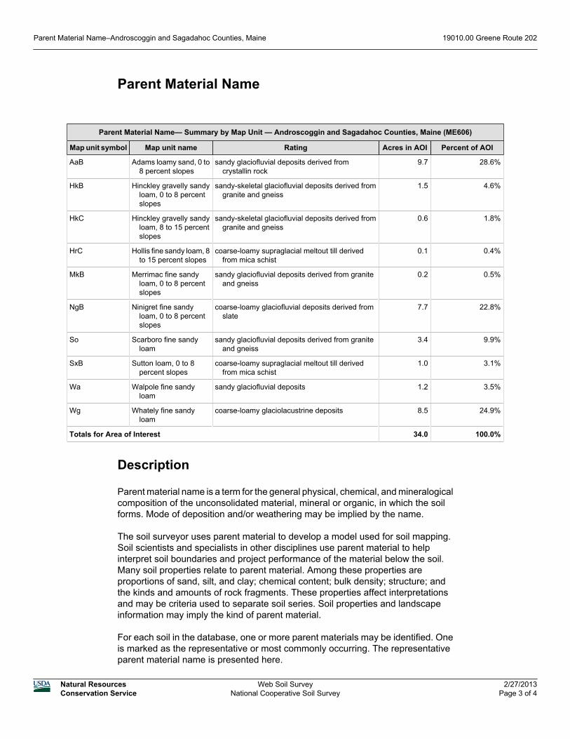
Parent Material Name
Parent Material Name— Summary by Map Unit — Androscoggin and Sagadahoc Counties, Maine (ME606)
Map unit symbol Map unit name Rating Acres in AOI Percent of AOI
AaB Adams loamy sand, 0 to8 percent slopes
sandy glaciofluvial deposits derived fromcrystallin rock
9.7 28.6%
HkB Hinckley gravelly sandyloam, 0 to 8 percentslopes
sandy-skeletal glaciofluvial deposits derived fromgranite and gneiss
1.5 4.6%
HkC Hinckley gravelly sandyloam, 8 to 15 percentslopes
sandy-skeletal glaciofluvial deposits derived fromgranite and gneiss
0.6 1.8%
HrC Hollis fine sandy loam, 8to 15 percent slopes
coarse-loamy supraglacial meltout till derivedfrom mica schist
0.1 0.4%
MkB Merrimac fine sandyloam, 0 to 8 percentslopes
sandy glaciofluvial deposits derived from graniteand gneiss
0.2 0.5%
NgB Ninigret fine sandyloam, 0 to 8 percentslopes
coarse-loamy glaciofluvial deposits derived fromslate
7.7 22.8%
So Scarboro fine sandyloam
sandy glaciofluvial deposits derived from graniteand gneiss
3.4 9.9%
SxB Sutton loam, 0 to 8percent slopes
coarse-loamy supraglacial meltout till derivedfrom mica schist
1.0 3.1%
Wa Walpole fine sandyloam
sandy glaciofluvial deposits 1.2 3.5%
Wg Whately fine sandyloam
coarse-loamy glaciolacustrine deposits 8.5 24.9%
Totals for Area of Interest 34.0 100.0%
Description
Parent material name is a term for the general physical, chemical, and mineralogicalcomposition of the unconsolidated material, mineral or organic, in which the soilforms. Mode of deposition and/or weathering may be implied by the name.
The soil surveyor uses parent material to develop a model used for soil mapping.Soil scientists and specialists in other disciplines use parent material to helpinterpret soil boundaries and project performance of the material below the soil.Many soil properties relate to parent material. Among these properties areproportions of sand, silt, and clay; chemical content; bulk density; structure; andthe kinds and amounts of rock fragments. These properties affect interpretationsand may be criteria used to separate soil series. Soil properties and landscapeinformation may imply the kind of parent material.
For each soil in the database, one or more parent materials may be identified. Oneis marked as the representative or most commonly occurring. The representativeparent material name is presented here.
Parent Material Name–Androscoggin and Sagadahoc Counties, Maine 19010.00 Greene Route 202
Natural ResourcesConservation Service
Web Soil SurveyNational Cooperative Soil Survey
2/27/2013Page 3 of 4

Main St
Meado
w Hill
Rd
Merrill Hill Rd
202
AaB
Wg
So
NgB
NgB
Wg
HkB
Wa
SxB
HkC
MkB
HrC
HrC
4065
00
4065
00
4066
00
4066
00
4067
00
4067
00
4068
00
4068
00
4069
00
4069
00
4070
00
4070
00
4071
00
4071
00
4072
00
4072
00
4073
00
4073
00
4074
00
4074
00
4075
00
4075
00
4892500
4892500
4892600
4892600
4892700
4892700
4892800
4892800
4892900
4892900
4893000
4893000
4893100
4893100
050
01,
000
1,50
025
0Fe
et0
100
200
300
50M
eter
s
44° 1
1' 8
''
70° 9' 26''
44° 1
0' 4
6''
70° 9' 25''
44° 1
0' 4
6''
44° 1
1' 8
''70° 10' 10''70° 10' 11''
Map
Sca
le: 1
:4,8
10 if
prin
ted
on A
siz
e (8
.5" x
11"
) she
et.
Dep
th to
Wat
er T
able
—A
ndro
scog
gin
and
Sag
adah
oc C
ount
ies,
Mai
ne(1
9010
.00
Gre
ene
Rou
te 2
02)
Nat
ural
Res
ourc
esN
atur
al R
esou
rces
Nat
ural
Res
ourc
esN
atur
al R
esou
rces
Con
serv
atio
n S
ervi
ceC
onse
rvat
ion
Ser
vice
Con
serv
atio
n S
ervi
ceC
onse
rvat
ion
Ser
vice
Web
Soi
l Sur
vey
Nat
iona
l Coo
pera
tive
Soi
l Sur
vey
2/27
/201
3P
age
1 of
4
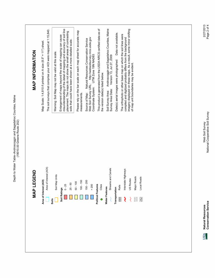
MA
P LE
GEN
DM
AP
INFO
RM
ATI
ON
Are
a of
Inte
rest
(AO
I)A
rea
of In
tere
st (A
OI)
Soils
Soi
l Map
Uni
ts
Soil
Rat
ings 0
- 25
25 -
50
50 -
100
100
- 150
150
- 200
> 20
0
Polit
ical
Fea
ture
sC
ities
Wat
er F
eatu
res
Stre
ams
and
Can
als
Tran
spor
tatio
nR
ails
Inte
rsta
te H
ighw
ays
US
Rou
tes
Maj
or R
oads
Loca
l Roa
ds
Map
Sca
le: 1
:4,8
10 if
prin
ted
on A
siz
e (8
.5" ×
11"
) she
et.
The
soil
surv
eys
that
com
pris
e yo
ur A
OI w
ere
map
ped
at 1
:15,
840.
War
ning
: Soi
l Map
may
not
be
valid
at t
his
scal
e.
Enl
arge
men
t of m
aps
beyo
nd th
e sc
ale
of m
appi
ng c
an c
ause
mis
unde
rsta
ndin
g of
the
deta
il of
map
ping
and
acc
urac
y of
soi
l lin
epl
acem
ent.
The
map
s do
not
sho
w th
e sm
all a
reas
of c
ontra
stin
gso
ils th
at c
ould
hav
e be
en s
how
n at
a m
ore
deta
iled
scal
e.
Ple
ase
rely
on
the
bar s
cale
on
each
map
she
et fo
r acc
urat
e m
apm
easu
rem
ents
.
Sou
rce
of M
ap:
Nat
ural
Res
ourc
es C
onse
rvat
ion
Ser
vice
Web
Soi
l Sur
vey
UR
L:
http
://w
ebso
ilsur
vey.
nrcs
.usd
a.go
vC
oord
inat
e S
yste
m:
UTM
Zon
e 19
N N
AD
83
This
pro
duct
is g
ener
ated
from
the
US
DA
-NR
CS
cer
tifie
d da
ta a
s of
the
vers
ion
date
(s) l
iste
d be
low
.
Soi
l Sur
vey
Are
a:
And
rosc
oggi
n an
d S
agad
ahoc
Cou
ntie
s, M
aine
Sur
vey
Are
a D
ata:
V
ersi
on 1
3, J
ul 2
7, 2
009
Dat
e(s)
aer
ial i
mag
es w
ere
phot
ogra
phed
: D
ata
not a
vaila
ble.
The
orth
opho
to o
r oth
er b
ase
map
on
whi
ch th
e so
il lin
es w
ere
com
pile
d an
d di
gitiz
ed p
roba
bly
diffe
rs fr
om th
e ba
ckgr
ound
imag
ery
disp
laye
d on
thes
e m
aps.
As
a re
sult,
som
e m
inor
shi
fting
of m
ap u
nit b
ound
arie
s m
ay b
e ev
iden
t.
Dep
th to
Wat
er T
able
–And
rosc
oggi
n an
d S
agad
ahoc
Cou
ntie
s, M
aine
(190
10.0
0 G
reen
e R
oute
202
)
Nat
ural
Res
ourc
esC
onse
rvat
ion
Serv
ice
Web
Soi
l Sur
vey
Nat
iona
l Coo
pera
tive
Soi
l Sur
vey
2/27
/201
3P
age
2 of
4

Depth to Water Table
Depth to Water Table— Summary by Map Unit — Androscoggin and Sagadahoc Counties, Maine (ME606)
Map unit symbol Map unit name Rating (centimeters) Acres in AOI Percent of AOI
AaB Adams loamy sand, 0 to 8percent slopes
>200 9.7 28.6%
HkB Hinckley gravelly sandyloam, 0 to 8 percentslopes
>200 1.5 4.6%
HkC Hinckley gravelly sandyloam, 8 to 15 percentslopes
>200 0.6 1.8%
HrC Hollis fine sandy loam, 8to 15 percent slopes
>200 0.1 0.4%
MkB Merrimac fine sandyloam, 0 to 8 percentslopes
>200 0.2 0.5%
NgB Ninigret fine sandy loam,0 to 8 percent slopes
69 7.7 22.8%
So Scarboro fine sandy loam 0 3.4 9.9%
SxB Sutton loam, 0 to 8percent slopes
61 1.0 3.1%
Wa Walpole fine sandy loam 15 1.2 3.5%
Wg Whately fine sandy loam 7 8.5 24.9%
Totals for Area of Interest 34.0 100.0%
Description
"Water table" refers to a saturated zone in the soil. It occurs during specifiedmonths. Estimates of the upper limit are based mainly on observations of the watertable at selected sites and on evidence of a saturated zone, namely grayish colors(redoximorphic features) in the soil. A saturated zone that lasts for less than a monthis not considered a water table.
This attribute is actually recorded as three separate values in the database. A lowvalue and a high value indicate the range of this attribute for the soil component. A"representative" value indicates the expected value of this attribute for thecomponent. For this soil property, only the representative value is used.
Rating Options
Units of Measure: centimeters
Aggregation Method: Dominant Component
Component Percent Cutoff: None Specified
Tie-break Rule: Lower
Depth to Water Table–Androscoggin and Sagadahoc Counties, Maine 19010.00 Greene Route 202
Natural ResourcesConservation Service
Web Soil SurveyNational Cooperative Soil Survey
2/27/2013Page 3 of 4


