geotechnical site investigation guidelines for … · geotechnical site investigation guidelines...
TRANSCRIPT

GEOTECHNICAL SITE INVESTIGATION
GUIDELINES
FOR BUILDING FOUNDATIONS
IN PERMAFROST
Prepared for:
Department of Public Works and Services
Government of the Northwest Territories
I. Holubec Consulting Inc.
January 2010


Geotechnical Site Investigation Guidelines for Building Foundations in Permafrost i
SUMMARY
A geotechnical site investigation is the process of collecting information and evaluating the
conditions of the site for the purpose of designing and constructing the foundation for a structure,
such as a building, plant or bridge. A geotechnical site investigation in permafrost regions is
more complex than in southern temperate climate regions because:
a) potential presence of ice within the soil or rock whose properties are temperature and
salinity dependent;
b) climate change is warming the ground thereby decreasing the strength of the frozen
ground and eventually thawing it and
c) the presence of saline soils in coastal areas.
Good planning for and management of a geotechnical site investigation is the key to obtaining
sufficient and correct site information for designing a structure in a timely manner and with
minimum cost for the effort needed.
The effort and detail of the geotechnical site investigation to obtain sufficient and correct site
information to select and design a foundation for a building in permafrost is complex. It depends
on:
a) design criteria of the proposed structure;
b) historic knowledge of general site conditions and building performance;
c) drilling equipment availability;
d) time of year the work needs to be done may determine the geotechnical site investigation
method and finally;
e) the overall costs.
The collection of geotechnical data and the preparation of a report for a proposed structure
should be considered in four phases:
1. Project definition prepared by the owner in conjunction with an architect, if selected. The
project definition consists of architectural/engineering foundation criteria such as loading
and settlement; on or above ground structure; service life of structure, and proposed
design/construction schedule.
2. Preliminary site and project evaluation conducted by the geotechnical consultant selected
for the geotechnical site investigation. It consists of preliminary site review of past
geotechnical investigations of nearby sites and a selection of likely foundation design(s)
based on published literature and the geotechnical consultant knowledge of the site. This
preliminary evaluation and a consensus by the owner are used to develop the detail of the
proposed geotechnical site investigation.

Geotechnical Site Investigation Guidelines for Building Foundations in Permafrost ii
It will also determine if this phase would be done in one or two steps. In the case of small
buildings located on good ground conditions, this phase could be done by means of an
office evaluation to be followed by the geotechnical site investigation.
In the case of a major building and possible difficult permafrost, this phase could be done
in two steps. It would include a preliminary site visit by a geotechnical engineer with
permafrost experience to collect visible data and performance information of existing
buildings in order to complete the office phase of the evaluation and discuss the findings
with the owner and architect, if selected, to prepare the detailed site program.
3. Geotechnical site investigation (test holes and sampling) and laboratory testing for soils
characteristics.
4. Geotechnical report preparation with recommended foundation system options.
The client may consider incorporating peer review in the overall process for projects that
are large and/or located in difficult permafrost conditions. This should not be viewed as a
confrontational exercise but as an additional resource to develop the best foundation
design.
The scope of these guidelines is to plan a geotechnical site investigation in frozen soils,
report the results from field exploration and laboratory testing in terms of internationally
recognized classification systems, and provide foundation design and construction
recommendations that address both the building requirements and climate change.
The planning and execution of geotechnical site investigation for buildings foundations in
permafrost is summarized herein.
1. Building Design Concept Definition
The building development project authority, with the assistance of an architect/engineer
building design consultant (if one has been selected), needs to outline the proposed
building functional concept and its approximate structural requirements. The information
that needs to be provided in a RFP and the execution of the geotechnical site
investigations is:
Item Criteria
General plan configuration and footprint of building, m2
Single or multi story
Slab-on-ground, above ground, crawlspace/basement, etc
Superstructure design and allowable settlement criteria
Building service life, years
Other

Geotechnical Site Investigation Guidelines for Building Foundations in Permafrost iii
2. Terms of Reference
The Geotechnical site investigation Report should contain the following major sections:
Preliminary site characterization
Actual field test holes, sampling and laboratory testing.
Assessment of the information collected and presenting it in recognized formats;
such as the ASTM Description and Classification Standards.
Recommendation of one or more foundation systems that fulfill the project
definitions.
These sections are described further as follows:
3. Preliminary Site Characterization (Description)
It is important that before a field investigation program is developed a preliminary site
characterization based on published literature and clients and consultants information be
prepared. The site characterization should include climate and ground temperature at
commissioning of the building and at the end of its service life.
The extent and timing of the preliminary site characterization is a function of the size and
settlement sensitivity of the building and the nature of the frozen ground. It can be an
office (desk) study based on available information and may include a site visit. For larger
and settlement sensitive buildings, it is suggested that a site visit be made during late
summer when the ground thaw is at its greatest, when surface drainage and groundwater
can be observed and test pits can be excavated at the proposed building site, and at
potential construction borrow materials. Test pits during the deepest thaw depth, during
August and September, allow a detailed examination of the first 3 m depth that may
consist of a stratigraphy of fill, organic and disturbed soil layers respectively and the
summer groundwater. This upper zone is frequently a critical zone in the design of the
foundation, its excavation and grading plan.
4. Test Holes and Sampling
Equipment availability and the costs of mobilization of the drill equipment for advancing
the test holes depends on road access. The four types of test hole advance equipment and
their applications are given in the table below.
Equipment Capability
Backhoe excavator Test pits in thawed ground during summer
Air-track drill Frozen ground and bedrock. Provides chips for soil description
and water content measurement to assess likely thaw
consolidation.
Augers mounted on truck or tracks Remoulded ground. As above but better quality of samples.
Core drills with cooled drill fluid Frozen cores. Best samples for visual classification and index
and engineering testing.

Geotechnical Site Investigation Guidelines for Building Foundations in Permafrost iv
The most frequently used equipment for test holes in the North are air-track (percussion)
drills and augers for drilling and sampling. This equipment is sufficient for the design of
most building foundations. For complex large structures it may be prudent to consider
core drills that can retrieve frozen soil cores.
5. Test Hole Number and Depth
It is recommended that for small and intermediate buildings all the geotechnical
information be collected in one geotechnical site investigation. This can readily be done
with a diligent preliminary site characterization.
It is suggested that, depending on the size of the building and the results of the
preliminary site characterization, 3 to 5 drill holes be advanced. Two to three of the test
holes should be advanced to a depth of about 20 m for several reasons: a) provide
information for deeper piles if this type of foundation is found desirable, b) be able to
assess the thaw consolidation of the frozen ground below any piles, or other foundation
type, should the permafrost thaw, and c) measure the existing frozen ground temperature
that is typically constant all year round at a depth generally between 15 and 20 m.
For large structures and complex frozen ground conditions, it may be prudent to plan the
geotechnical site investigation in two stages because:
a) first investigation would characterize the site to determine the best suited
foundation type and make any adjustments to the building base and
b) second investigation would determine more precisely geotechnical permafrost
engineering properties and concentrate the drill hole locations under the critical
points of the building.
The advantage of a two stage approach is also beneficial because structural design or the
location of the building may change due to the findings from the first investigation.
6. Ground Temperature Measurement
Ground temperature profile shall be measured in 15 to 20 m deep test holes by installing
thermistor cables with individual thermistor sensors at progressively greater spacing with
depth. Likely location of thermistors could be: 0.5, 1.5, 3.0, 5.0, 7.5, 10, 15 and 20 m
depth below ground surface. Thermistor operation shall be checked before installation
and then ground temperatures measured: immediately after installation, two days later,
and at the completion of the investigation. It would be beneficial to arrange for
subsequent thermistors readings to be made on at least a monthly basis for one year.

Geotechnical Site Investigation Guidelines for Building Foundations in Permafrost v
7. Test Hole Stratigraphic Description and Sampling
It is important that the progress of test holes advance be observed by a geotechnical
technologist or engineer with permafrost experience to document soil stratigraphies, their
changes, and the presence of ice inclusions.
Samples should be taken at 1.5 m depth intervals and sealed in plastic bags for transport
to a laboratory for testing. Disturbed samples are derived from backhoe and air-track and
auger drills. Drilling with coring capability will provide frozen cylindrical cores. In this
case, cylindrical cores of representative frozen soil conditions shall be secured, wrapped
in plastic and aluminum foil, and transported to the laboratory in a frozen state. In
addition, representative broken/disturbed samples shall be collected to provide samples at
1.5 m depth intervals for laboratory testing.
8. Laboratory Testing
Laboratory tests to obtain index properties of the frozen ground will suffice in the
majority of geotechnical site investigations. The index properties will be obtained by
means of: water content, particle size distribution and liquid and plastic limit tests. The
number of tests to be conducted should be as follows:
Water content – on all samples.
Particle size distribution – 3 to 5 tests from each major soil strata.
Liquid & plastic limits – 3 to 5 tests from each major soil strata if soil is observed
to have plasticity.
Laboratory testing for engineering properties may be required for large buildings on
complex frozen ground stratigraphy. The types of engineering tests that may be
conducted are thaw consolidation, and less likely, creep strength and thermal properties
tests. These are not discussed further because of their infrequency of being conducted.
9. Soil Classifications
All frozen or unfrozen soil strata shall be classified according to ASTM classification
systems. The soils should be described by the Soil Group Symbols established by means
of laboratory test results.
10. Photographs
The site and the drill equipment in work progress shall be document by photographs. In
addition, photographs shall be taken of representative disturbed samples and all frozen
soil and rock cores.

Geotechnical Site Investigation Guidelines for Building Foundations in Permafrost vi
11. Report
The report content should follow the report outline given in Section 6.0. The key issues
that should be noted shall be:
a) Restate project definition;
b) Characterize the site so that surrounding conditions that may impact on the design
and performance of the building foundation are understood and designed for;
c) State the present and the projected end of the building service life, climate and
ground temperatures;
d) Classify the soil strata according to recognized ASTM Standards, based on
quantitative laboratory results;
e) State the significance of the stratigraphy established by the test hole program,
measured ground temperature and the impact of climate warming rate on the
recommended building foundation design(s);
f) Identify foundation options appropriate for the proposed service life of the
building; and
g) Provide guidance for the construction and construction scheduling of the
foundation for the building.
12. Peer Review
The project management team may consider a peer review process by an independent
senior geotechnical engineer with permafrost experience for the geotechnical site
investigation program and the development of building foundations. The purpose should
be to bring in additional technical resources to result in attaining the most suitable
building foundation design.
It needs to be reiterated that design of building foundations in permafrost is complex, and
it has become more complex by climate change that is warming and even thawing
permafrost ground. Furthermore, there are limited case histories on the performance of
building foundations under the present permafrost changes. Any additional technical
resources for larger or complex projects would likely be beneficial.

Geotechnical Site Investigation Guidelines for Building Foundations in Permafrost
TABLE OF CONTENTS
1.0 INTRODUCTION .................................................................................................................................... 1
1.1 GENERAL .............................................................................................................................................. 1 1.2 SCOPE ................................................................................................................................................... 1 1.3 BACKGROUND ....................................................................................................................................... 2
2.0 PLANNING .............................................................................................................................................. 3
2.1 GEOTECHNICAL SITE INVESTIGATION PROGRAM OVERVIEW ................................................................ 3 2.2 PLANNING STEPS................................................................................................................................... 7
2.2.1 Step 1 – Building Design Concept Definition ................................................................................. 7 2.2.2 Step 2 – Preliminary Site and Project Evaluation ............................................................................ 7 2.2.3 Step 3 – Geotechnical Site Investigation and Laboratory Testing ................................................... 8 2.2.4 Step 4 – Analyses and Geotechnical Report Preparation ................................................................. 8
3.0 GEOTECHNICAL SITE INVESTIGATION COMPONENTS ............................................................... 8
3.1 GENERAL .............................................................................................................................................. 8 3.2 SITE CHARACTERIZATION ..................................................................................................................... 8
3.2.1 Geomorphology & Bedrock ............................................................................................................ 8 3.2.2 Terrain ............................................................................................................................................. 9 3.2.3 Surface Drainage and Groundwater ................................................................................................. 9 3.2.4 Seismicity ........................................................................................................................................ 9 3.2.5 Construction Materials .................................................................................................................... 9 3.2.6 Transportation and Site Access ..................................................................................................... 10
3.3 CLIMATE ............................................................................................................................................. 10 3.3.1 Air Temperature ............................................................................................................................ 10 3.3.2 Climate Warming .......................................................................................................................... 11 3.3.3 Freezing Index ............................................................................................................................... 12 3.3.4 Precipitation and Surface Drainage ............................................................................................... 13
3.4 GROUND TEMPERATURE AND PERMAFROST ....................................................................................... 14 3.4.1 Ground Temperature ..................................................................................................................... 14
3.5 PERMAFROST ...................................................................................................................................... 16 3.5.1 Frozen Soil Description ................................................................................................................. 17
3.6 UNFROZEN SOIL CLASSIFICATION AND PROPERTIES ........................................................................... 17 3.6.1 General .......................................................................................................................................... 17 3.6.2 Soil Description and Classification ............................................................................................... 18 3.6.3 Index Properties ............................................................................................................................. 20 3.6.4 Engineering Properties and Parameters ......................................................................................... 22
4.0 DRILLING, SAMPLING AND LABORATORY TESTING ................................................................ 24
4.1 DRILLING METHOD ............................................................................................................................. 24 4.2 SAMPLING ........................................................................................................................................... 27 4.3 LABORATORY TESTING AND PROPERTIES ........................................................................................... 27 4.4 BEDROCK ............................................................................................................................................ 28
5.0 FIELD & LABORATORY PROGRAM ................................................................................................ 29
5.1 GENERAL ............................................................................................................................................ 29 5.2 TEST PITS AND DRILLING .................................................................................................................... 29 5.3 TEST HOLE DEPTH AND FREQUENCY .................................................................................................. 30
5.3.1 Test Pits ......................................................................................................................................... 30 5.3.2 Number and Depth of Drill Holes ................................................................................................. 30

Geotechnical Site Investigation Guidelines for Building Foundations in Permafrost
TABLE OF CONTENTS
5.4 GROUND TEMPERATURE ..................................................................................................................... 31 5.5 CLASSIFICATION, SAMPLING AND LABORATORY TESTING .................................................................. 31
5.5.1 Engineering Properties .................................................................................................................. 32
6.0 REPORT OUTLINE ............................................................................................................................... 33
6.1 INTRODUCTION ................................................................................................................................... 33 6.2 BACKGROUND ..................................................................................................................................... 33 6.3 SUBSURFACE CONDITIONS .................................................................................................................. 35
6.3.1 Investigation Program Summary ................................................................................................... 35 6.3.2 Subsurface Conditions ................................................................................................................... 35 6.3.3 Ground Thermal Regime (Ground Temperature) ......................................................................... 36 6.3.4 Construction Materials .................................................................................................................. 37 6.3.5 Design Properties and Criteria ....................................................................................................... 37
6.4 DESIGN RECOMMENDATIONS .............................................................................................................. 37 6.4.1 Foundation Design and Alternatives ............................................................................................. 37 6.4.2 Site and Construction Material Preparation ................................................................................... 38 6.4.3 Grading .......................................................................................................................................... 38 6.4.4 Construction Aspects and Schedules ............................................................................................. 38
6.5 CONCLUSIONS ..................................................................................................................................... 38 6.6 LIMITATIONS OF THE INVESTIGATION ................................................................................................. 38 6.7 APPENDICES .................................................................................................................................... 39
6.7.1 TEXT ............................................................................................................................................. 39 6.7.2 GRAPHICS & DATA ................................................................................................................... 39
7.0 SELECTED ASTM INTERNATIONAL STANDARDS....................................................................... 40
8.0 REFERENCES ....................................................................................................................................... 42
9.0 APPENDIX ............................................................................................................................................. 43

Geotechnical Site Investigation Guidelines for Building Foundations in Permafrost 1
1.0 INTRODUCTION
1.1 General
A geotechnical site investigation is the process of collecting information and evaluating
the conditions of the site for the purpose of designing and constructing the foundation for
a structure, such as a building, plant or bridge. A geotechnical investigation in permafrost
regions is more complex than in southern temperate climate regions because:
a) potential presence of ice within the soil or rock whose properties are temperature
and salinity dependent;
b) climate change is warming the ground and thawing the permafrost; and
c) the presence of saline soils in coastal areas.
The following paragraph from Johnston 1981 is worthwhile repeating:
The importance of proper selection and investigation of sites and routes in permafrost
areas cannot be overemphasized. Reconnaissance and detailed site and route studies
must be made, and environmental considerations and the availability of construction
materials must be taken into account. Increased costs of construction, operation and
maintenance, as well as unsatisfactory performance of engineering structures,
inevitably result when there is a lack of information on conditions and other terrain
factors.
In the time since the above observation was made, the impact of climate warming on the
stability of permafrost has been identified and has to be addressed in a geotechnical site
investigation report. Climate warming includes the ground temperature changes that may
occur over the service life of the proposed structure, and foundation design has to be
suitable for the final year of the structure.
The impact of climate warming on total service life of structures founded on permafrost
has to be considered.
1.2 Scope
The design of a foundation system requires the collection and analysis of the following
site related information:
Physiography and geology plus topography & surface cover
Climate
Subsurface conditions
Ground temperatures
Hydrology and drainage
Hydrogeology
Construction materials

Geotechnical Site Investigation Guidelines for Building Foundations in Permafrost 2
The effort and detail of the site study and the establishment of design recommendations
varies depending on: the nature of the site, available historic information, the structure
loads and settlement criteria of the proposed building.
The scope of this document (guidelines) is to provide a guide for:
a) planning
b) conducting a geotechnical site investigation
c) preparing a geotechnical site investigation report
Information in this document is grouped into four topics:
a) project planning and management
b) classification systems for soils and permafrost that should be used in a report
c) typical climate parameters and soil/permafrost index and engineering properties
d) geotechnical site investigation report content
To aid in the process of the geotechnical site investigation and preparation of a report,
some common methods of soil investigation and sampling are noted, comments and
typical values for relevant properties are provided, and classification systems to be used
in a geotechnical site investigation report are summarized. The information which should
be presented in a report is given and an outline of the geotechnical site investigation
report suggested in Section 6.0, “Report Outline”.
1.3 Background
These guidelines are prepared to assist in planning, executing and reporting a
geotechnical site investigation for building and infrastructure foundations located in
permafrost. The appropriate detail of this process is determined by the magnitude and
required performance of the proposed structure, site conditions, foundation type suitable
for the structure, timing and costs.
This guideline is based on references given in the report and the writer‟s field and design
experience. Four main documents that guided the writer are:
Permafrost, Engineering Design and Construction
(G.H. Johnston 1981, out of print)
Arctic and Subarctic Construction Foundations for Structures
(U.S.A. Department of the Army and the Air Force, October 1983, out of print)
Canadian Foundation Engineering Manual, 4th
Edition
(Canadian Geotechnical Society 2006)
ASTM International Standards
(Individual Standards)

Geotechnical Site Investigation Guidelines for Building Foundations in Permafrost 3
The first two are excellent reference documents on permafrost, design and construction.
However, they do not address climate warming that is now or will shortly be influencing
the performance of structures in permafrost. Furthermore, these two documents are out of
print. The Canadian Foundation Engineering Manual addresses geotechnical site
investigations and design of foundations for sites with no permafrost, typically of
southern Canada.
The ASTM International Standards provide a framework for describing the ice content in
permafrost as observed during the field investigation and a formalized method of
classifying the soils encountered. It is suggested the parties preparing and using the site
information should obtain at least the first four ASTM Standards given in Section 8.0.
Three of these Standards provide procedures prepared for unfrozen soils that are also
applicable to frozen soils, and the fourth Standard provides a procedure for describing
frozen soils. The remaining Standards given in Section 8 relate to test methods.
This document updates the information on geotechnical site investigation given in
Johnston‟s textbook in regard to the present and future climate. It does not cover in as
great detail the material given in that textbook that was prepared with the contribution of
31 experts.1
2.0 PLANNING
2.1 Geotechnical Site Investigation Program Overview
Good planning for and management of a geotechnical site investigation program is the
key to obtain sufficient and correct site information for designing a building foundation
in a timely manner and with minimum cost for the effort needed.
The effort and detail of the geotechnical site investigation program in permafrost is
complex. It depends on:
a) design criteria of the proposed building;
b) historic knowledge of general site conditions and performance of existing
buildings;
c) drilling equipment availability;
d) time of the year the work needs to be done that may determine the geotechnical
site investigation method and costs.
1 The reader is encouraged to obtain access to “Permafrost Engineering Design and Construction” through
inter library load from Aurora College, University of Alberta, and similar technical reference collections,
for a comprehensive review of engineering designs and construction in permafrost, before the advent of
acknowledged climate warming.

Geotechnical Site Investigation Guidelines for Building Foundations in Permafrost 4
The collection of geotechnical data and the preparation of a report for a proposed
structure should be considered in four activities:
1. Project definition prepared by the owner in conjunction with an architect, if
selected. The project definition consists of architectural/engineering foundation
criteria such as: loading and settlement, on or above ground structure, service life
of structure and proposed design/construction schedule.
2. Office study. Preliminary site assessment and selection of likely foundation
design(s) based on published literature and knowledge of the geotechnical
consultant of the site. This study may include a site visit by a geotechnical
engineer with permafrost experience.
3. Geotechnical site investigation (test holes and sampling) and laboratory testing to
establish soil characteristics.
4. Geotechnical report preparation.
An outline of a geotechnical site investigation program and the components that should
be considered in its development are presented in Table 1. A geotechnical site
investigation program consists of a combination of the components shown in the table
and depends on the type of structure, knowledge of the local conditions, and availability
of exploration equipment.
The effort and detail of the program vary between projects. A desk top study with a
follow up site visit by a geotechnical engineer with some test pits during the summer may
be sufficient for small structures that can tolerate some settlement and are located in an
area with „cold‟ permafrost. On the other hand, a multi-level large structure with low
settlement tolerance may require rotary core drilling to obtain frozen cylinder soil
samples for laboratory testing to determine engineering properties such as: thaw
consolidation, creep, and thermal properties (thermal conductivity, heat capacity, and
similar physical data.
Good planning and execution of a geotechnical site investigation program must consider
four steps described in Section 2.2 that may involve the following major participants:
a) Building developer – who understands the purpose of the proposed building; will
pay for the investigation, and construction, and will inherit the maintenance of the
structure.
b) Architects & Engineers – who design the building and understand the tolerances
of the structure. They also design the site contouring and utilities that may affect
the foundation performance over time.

Geotechnical Site Investigation Guidelines for Building Foundations in Permafrost 5
c) A Geotechnical Consultant – who will determine the site characteristics by field
investigation and laboratory testing and who recommends one or more foundation
types that will satisfy the requirements specified by the Architect and Engineer.
The consultant should also address the construction constraints, identify an
optimal construction schedule for the excavation, foundation installation and
grading, and may provide construction overview/control.
d) Peer Review – on large or performance sensitive structures, the building
developer may engage a geotechnical permafrost engineer expert to review and
provide advice on the geotechnical program and recommendations.

Geotechnical Site Investigation Guidelines for Building Foundations in Permafrost 6
Table 1. Geotechnical Site Investigation Program Components
Initial Structure Definition
1. Single or multi-story
2. Ground access requirements
3. Settlement sensitivity
4. Service life of building
5. Design & construction schedule
Preliminary Site Evaluation
1. Site characterization
2. Climate and ground temperature
3. Ground stratigraphy & permafrost regime
4. Local precedents & availability
of earth construction materials
Structure Class
A - Low sensitivity B - Intermediate sensitivity C - Deformation Sensitive
Small & one story Large plan area Large area & multi-story buildings
Not highly sensitive to Sensitive to differential settlement Sensitive to differential settlement
differential settlement
Possible site investigation methods
Test pit during summer Percussion drill Rotary drill with frozen cores
Percussion drill Auger drill Diamond drill with frozen core
(airtrack) Rotary drill with frozen cores
Auger drill Diamond drill with frozen core Note: both with cooled fluid
Frozen soils - sampling
Disturbed samples Disturbed chip & grab samples Undisturbed frozen core
Possibly, undisturbed frozen core for laboratory testing as given below
Laboratory Testing
Index properties Index Properties As in A & B
Water content, (as in A) As in A plus
Gradation Photographs of cores Thaw consolidation
Atterberg limits Lab in-situ density Frozen core creep strength
Salinity
Compaction tests
Bedrock - sampling
Rock chips Rock chips & cores Cores
Measurements & tests
None Core recovery Core recovery
Rock Quality Determination (RQD) Rock Quality Determination (RQD)
Ground Temperatures
Thermistor cable(s) Thermistor cable(s) installation (short or Thermistor cable(s) installation with
installation (short or long term monitoring) consider data loggers data loggers (Monitor at least monthly
long term monitoring) for one year or longer)
Potential other investigation methods
Not needed Seismic refraction As in B plus
Electromagnetic terrain conductivity Pressuremeter
Ground penetrating radar Electrical resistivity

Geotechnical Site Investigation Guidelines for Building Foundations in Permafrost 7
2.2 Planning Steps
2.2.1 Step 1 – Building Design Concept Definition
The first step in a geotechnical investigation is the concept design of the building by the
client and architect/engineer. This information is required for setting the terms of
reference for a geotechnical site investigation and enables the geotechnical consultant to
understand specifics of the proposed structure. Information that should be addressed is:
Building description; location, size, configuration (number or stories), above or
on ground. And a general site plan with the building outline.
Magnitude and type of loading
Service life of proposed building
Tolerance of building to settlement (total & differential).
Ancillary works (utilities) and structures
Schedule limitations
At this stage the building developer and architect/engineer should select a geotechnical
consultant to carry out the geotechnical site investigation in two stages;
a) preliminary site evaluation
b) detailed geotechnical site investigation with test holes
The reason for conducting it in two stages is that the first stage may identify more clearly
the key geotechnical condition and this in turn may lead to modifying or alternating the
proposed foundation type. This could result in adjustment of the drilling and testing
program and result in the development of a more effective geotechnical site investigation
program.
2.2.2 Step 2 – Preliminary Site and Project Evaluation
The geotechnical consultants should gather available information in the client‟s domain,
the consultant‟s office, published geological reports and maps to prepare a preliminary
assessment of the site and suggest suitable foundation design options for the proposed
structure. The amount of information available will vary with site.
The geotechnical consultant shall summarize and assess the following information:
Surficial soil and bedrock
Likely site stratigraphy and hydrology
Climate, design air temperature and likely climate warming rate and mean annual
ground temperature and annual thaw depth
Surface hydrology and hydrogeology that may impact the building foundation
Availability of granular construction material for foundation base and grading
Potential foundation options and local precedents, if any
Geotechnical Site Investigation Guidelines for Building Foundations in Permafrost 8
This information could be used to either evaluate the favoured foundation design, and if
necessary, advise of alternative design options, or identify a likely foundation design.
The results of this summary and discussion with the building developer and
architect/engineer will lead to the acceptance of a detailed geotechnical site investigation
program.
2.2.3 Step 3 – Geotechnical Site Investigation and Laboratory Testing
The actual geotechnical field investigation is the most critical and costly part of the work.
Therefore, it should be based on information prepared in steps 1 and 2 and executed
based on information provided in the next chapters. Discussion of this step will be given
later in Chapter 4 after the components given in Table 1 are discussed, guidelines
provided and typical values given, if applicable. The discussion of the site
characterization and investigation are given in Chapter 3.
2.2.4 Step 4 – Analyses and Geotechnical Report Preparation
This step is discussed in Chapter 5.
3.0 GEOTECHNICAL SITE INVESTIGATION COMPONENTS
3.1 General
The following is a discussion of the significance of the geotechnical site investigation
components and provides information, guidelines and typical values for these
components.
3.2 Site Characterization
Site characterization provides an understanding of the formation of the underlying ground
and its likely properties and homogeneity. This work should be done in the preliminary
site evaluation (Step 2) since it will guide the development of the geotechnical field site
investigation and assist in interpreting the results of the information obtained in the
detailed investigation. The information that should be considered in site characterization
is given below.
3.2.1 Geomorphology & Bedrock
Geomorphology indicates the process of how the site ground was formed and thereby
also likely the type of material, its properties and homogeneity. It is recommended that
published information, such as the Geological Survey of Canada reports and maps, air
photos, Google Earth and a site visit be used to describe the site as fluvial, lacustrine,
solifluction, marine deposits, till, esker, and other geological structures. The major
deposition category groups represent unique type of soils and suggest the heterogeneity
of the deposits.

Geotechnical Site Investigation Guidelines for Building Foundations in Permafrost 9
The characterization should include the identification of the bedrock types at the
immediate site and vicinity, the thickness of soil overburden and presence of rock
outcrops in the vicinity. This information is useful for deciding if the structure could be
founded on bedrock and identifies granular material that could be obtained from quarries
if sand and gravel deposits are scarce or not available.
3.2.2 Terrain
Terrain is the description of the surface features of the immediate site. This may include
the slope and orientation of the ground surface, vegetation such as: trees, shrubs, moss
and similar plant cover, surface drainage description that includes the presence or
proximity of creeks and ponds and rock outcrops. Availability of a topographic map of
the site and site photographs is greatly helpful.
The terrain description should include the description of existing and adjacent structures
and if the site was previously occupied by a structure(s) that was removed and the ground
subsurface and surface backfilled/modified.
3.2.3 Surface Drainage and Groundwater
Surface drainage is present only during the warm part of the year during snow thaw and
when it rains. In permafrost the groundwater is normally restricted to the near surface
annual thaw zone (active layer) that is normally 1 to 3 m deep in soils. Surface water and
groundwater may cause construction problems: erode final grading around the building,
flood basements and cause ice lensing and frost heave during the fall freeze up.
Therefore, it is necessary to identify these in the investigation so that these features can
be considered in the selection and design of the foundation and the grading and drainage
around the building.
3.2.4 Seismicity
The majority of the Northwest Territories is in a low seismic risk zone (NRC Atlas) and
therefore seismicity has little impact on the design of structures. Seismicity may be of
concern in the western region of Northwest Territories that lies in or adjacent to the
Rocky Mountains. Comment on seismicity for the particular site in question is prudent in
a geotechnical report.
3.2.5 Construction Materials
Type and availability of granular construction material is important in the design of the
foundation and site grading and minimizing their cost. Construction materials may be
required for concrete, pipe or liner bedding, granular pads, road base and surface course.
Even silty or clayey till has its use in applications such as: subgrade for roads and
foundations and groundwater control.

Geotechnical Site Investigation Guidelines for Building Foundations in Permafrost 10
The geotechnical consultant should identify sources of the granular and other
construction materials, estimate their quantities and establish their properties. Granular
construction sources that should be identified are:
a) Granular that may be of greatest demand may have limited availability
b) rock quarries whose blasted rock requires crushing and screening to produce
excellent structural granular fill
c) native soils that may be used as general fill or subgrade topped with high quality
granular
Native soil may be obtained directly from foundation excavation if the building has a
basement or crawl space.
3.2.6 Transportation and Site Access
Access to the site impacts greatly the costs of bringing in construction equipment and
materials and the scheduling of construction. The access to sites in the North varies
greatly from being remote where access has to be built to having an all season road that
connects the site to a large southern community. Other access means may be by ice road,
marine transport during the short summer shipping season and by aircraft.
3.3 Climate
3.3.1 Air Temperature
Air temperature is the main factor that determines the presence and future changes of
permafrost and it has been observed that the ground temperatures are warmer than the air
temperatures in northern Canada. Air temperature is the main factor that determines the
presence and future changes of permafrost. An approximate relation between mean
annual air temperature (MAAT) and mean annual ground temperature (MAGT) shows
the MAGT to be about 4.5°C warmer than the MAAT (Smith & Burgess 2000).
This means that air temperature records can be used to obtain a preliminary estimate of
the ground temperature at sites where no ground temperature measurements are available
for the design year.
However, the MAAT changes from year to year and has been increasing during the last
200 years. This means that the design MAAT for a new project has to be derived from a
linear trend of MAAT records from the nearest meteorological station(s) that has 30 or
more years of records.
The development of the MAAT linear trend analysis is illustrated in Figure 1 using data
from Inuvik, NT.

Geotechnical Site Investigation Guidelines for Building Foundations in Permafrost 11
Figure 1 Mean Annual Air Temperatures and Air Temperature Design Values
Inuvik, NT (Data from EC climate office)
The data in Figure 1 illustrate:
MAAT air temperatures fluctuate greatly from year to year,
A linear trend analysis shows a warming rate of 0.74°C per decade (based
on 40 year span).
The linear trend suggests a design MAAT for 2008 to be -7.1°C. It is noted
that recent years have recorded a low MAAT of -10.7°C in 1994 and a high
MAAT of -4.5°C in 1998.
Historic air temperature data from meteorological stations can be obtained from
Environment Canada advanced weather search at:
http://climate.weatheroffice.ec.gc.ca/advanceSearch/searchHistoricData_e.html.
3.3.2 Climate Warming
It is essential that the foundation for the proposed building be designed for the service life
of the building. This means that the design of the foundation in permafrost has to
consider the ground temperature parameters at the end of the service life of the building
that could be about 50 years in the future. Since the ground temperatures will be warming
at a similar rate as the air temperatures, the air climate warming rate can be used to
estimate the ground temperature at the end of the service life of the structure.
y = 0.074x - 154.721
-14
-12
-10
-8
-6
-4
1940 1960 1980 2000 2020 2040Year
Mean
an
nu
al air
tem
pera
ture
, d
eg
C
All data
1968 to 2007
10 per. Mov. Avg. (All data)
Linear (1968 to 2007)
Inuvik 1958 - 2008(68° 18N 133° 29W, El 68m)
MAAT -7.1°C in 2008

Geotechnical Site Investigation Guidelines for Building Foundations in Permafrost 12
A climate warming rate to be used for the estimation of future air temperatures, and
therefore ground temperatures, is still under discussion and will likely continue for some
time. A recent report issued by National Resources Canada (2007) suggested that the
median climate warming for the western area of the North is about +6.0°C with a high of
+12.5°C. from years 1961-1990 to a period 2070-2099; this translate to a climate
warming rate of 5.5°C/100 years for a median estimate and 11.4°C/100 for a high
estimate.
It is suggested that until newer information becomes available, a warming rate of 0.8°C
per decade can be assumed and be used to estimate the likely ground temperature at the
end of the service life of a new building. This is also supported by the linear trend line for
Inuvik (Figure 1) that shows a warming rate of 0.74°C per decade.
3.3.3 Freezing Index
It is necessary to estimate the freezing index (FI) at the start of the service life of the
proposed building for the design of a thermosyphon foundation if it is considered for the
proposed building. The freezing index is the cumulative number of degree-days below
0°C for a given period. It has been decreasing over the years due to climate warming
similar to the mean annual air temperature. This decrease is illustrated with data from
Inuvik, NT in Figure 2. This decrease has to be taken into account in the design of
thermosyphon foundations that have to perform to the end of the service life of the
building that could be 30 to 50 years.
One method to estimate the FI at the end of the service life of the building is to extend the
linear trend line of freezing index to the service end year of the building. For example,
the FI at Inuvik would change from 3,890 C degree-days in 2010 to 3,030 C degree-days
in 2050 over a 40 year period.
Figure 2 shows that the freezing index at Inuvik has been decreasing at about 215°C days
per decade.

Geotechnical Site Investigation Guidelines for Building Foundations in Permafrost 13
Figure 2 Freezing Index Changes at Inuvik since 1958, NT (Based on EC data)
Example air temperature design data for an assumed building with service life of 40 years
completed in Inuvik, NT, in 2008 is given in Table 2.
Table 2 Air and Ground Temperature Data for Inuvik, NT
Parameter Value in
2008
Value in
2048
MAAT, degrees C -7.1 -3.1
Standard Deviation, °C 0.8 0.8
Estimated MAGT, C -2.6 +1.4
Anticipated warming rate per decade, Centigrade Degree (°C)
Median 0.8
Maximum 1.0
Freezing Index, degree C days 3930 3060
3.3.4 Precipitation and Surface Drainage
Precipitation in the permafrost region is relatively low, being generally less than 300 mm
per year, and is practically equally distributed between snow and rain. Its impact on
building foundation design is the need to control the snow melt water during spring
runoff and rainfall runoff during the summer. The geotechnical report should provide the
mean annual rainfall and total precipitation for grading guidance. It should be noted that
the meteorologists anticipate that precipitation may increase by 15 to 30% in the North
(NRC 2007).
Inuvik, NT
y = -21.553x + 47211
2000
3000
4000
5000
6000
1940 1960 1980 2000 2020 2040
Fre
ezin
g I
nd
ex
, d
eg
ree C
da
ys

Geotechnical Site Investigation Guidelines for Building Foundations in Permafrost 14
The report should also address any physical features of the site that could adversely
impact the foundation due to ground and surface water movement during the summer and
the grading requirements to control this water flow. Items that should be commented on
are: slope and vegetation cover of the site, presence of creeks and nearby ponds;
likelihood of a high groundwater table in the active layer during the summer, and any
other features noted.
3.4 Ground Temperature and Permafrost
3.4.1 Ground Temperature
The knowledge of the ground temperature (soil and rock) at the time of construction and
its estimated value at the end of the service life of a structure is required for the design of
foundations at sites with frozen soils with ice content.
The definition of permafrost is a ground (soil or rock and included ice and organic
material) that remains at or below 0°C for at least two consecutive years (Everdingen
1998, revised 2002). It is important to note that there are no concerns with founding
buildings on rock or coarse sands and gravels with little ice. The design challenges
develop in frozen fine grained soils, such as fine sands, silt, clay and a mixture of these
soils with ice.
It has to be noted that ice in fine grained soils may start to thaw around -0.5°C, and
design criteria for adfreeze piles may require a maximum ground temperature of -2°C.
Furthermore, saline soils have a much lower freezing/thawing temperature than 0ºC.
Mean annual ground temperature (MAGT) is used in the design of building foundations.
It is not a constant. It varies greatly over the year in the near surface depth, less than 10
m, and increases with depth as given by a gradient illustrated in Figure 3. The thermal
gradient was noted to be about 1°C per 54 m depth (Johnston 1981).
The zero ground temperature amplitude observed at a depth of about 15 m suggests that
the MAGT can be estimated from a one time ground temperature measurement in a drill
hole 15 to 20 m deep drilled any time of the year.
The depth of the annual thaw, active freeze-thaw zone, can be obtained by either
measuring the ground temperatures profile on a regular basis over the year or by test pits
or holes conducted in mid August when a maximum thaw is normally observed. It has to
be noted that the depth of the freeze-thaw zone is very dependent on the vegetation,
thickness of organic layer and groundwater during the thaw. Changes to these during site
preparation and grading of the site will likely change the depth of the annual thaw. The
freeze thaw zone would be deeper if the vegetation and organic layer are removed.

Geotechnical Site Investigation Guidelines for Building Foundations in Permafrost 15
It has to be realized that the MAGT is not constant but has been increasing over the years
and will continue to do so due to recent climate warming. The recent changes of the
ground temperature can be illustrated from the observations at Inuvik, NT. MAGT in
1961 as reported in Smith & Burgess (2000) was -4.6°C. Ground temperature
measurement in 2008 (AMEC 2008) gave a ground temperature of -2.2°C at 20 m that
would be representative of the MAGT. However, for a structure to be constructed at the
present time, it is necessary to consider the likely ground temperature increase over the
service life of the building and the implication on building foundation performance.
Figure 3 Typical Ground Temperature Regime in Permafrost.
It needs to be noted that as permafrost warms due to climate warming, the ground
temperature at about 15 m may temporarily remain constant around -0.3°C to -0.5°C for
some 10 years or so because of the latent heat of fusion; especially in ice rich soils.
It is suggested that the design MAGT be estimated as follows:
1) By monitoring the ground temperatures with thermistor cable that is equipped
with 7 or more thermistor sensors at increasing spacing with depth to 15 to 20 m.
It is suggested that ground temperatures be measured on at least a monthly basis
for a year.
2) As above, but reading only for a month, or until the thermal condition recovers
from the drilling that will establish the MAGT at about the depth with zero
temperature fluctuation.
ACTIVE LAYER
GROUND SURFACE
°C
+--
MEAN ANNUAL
GROUND TEMPERATURE
MINIMUM MONTHLY
MEAN TEMPERATURE
MAXIMUM MONTHLY
MEAN TEMPERATURE
DEPTH OF ZERO
ANNUAL AMPLITUDE
~15m
GEOTHERMAL
GRADIENT
PERMAFROST
PERMAFROST TABLE
ACTIVE LAYER
GROUND SURFACE
°C
+--
MEAN ANNUAL
GROUND TEMPERATURE
MINIMUM MONTHLY
MEAN TEMPERATURE
MAXIMUM MONTHLY
MEAN TEMPERATURE
DEPTH OF ZERO
ANNUAL AMPLITUDE
~15m
GEOTHERMAL
GRADIENT
PERMAFROST
PERMAFROST TABLE

Geotechnical Site Investigation Guidelines for Building Foundations in Permafrost 16
3) In known cold permafrost, such as locations in western Arctic Islands, the MAGT
could be derived from historic measurements and correlation to the MAAT.
The geotechnical site investigation report should provide:
MAGT for the structure design year and how it was established.
Likely and high climate warming rates.
Estimated MAGT value(s) at the end of the service life of the new structure.
Estimate depth of the active layer for the completed ground beneath and around
the structure.
The post-construction active layer depth may differ from the existing undisturbed
condition. Shallow active layer depth is observed in areas with thick organic materials
underlain by fine grained soils with large water contents. Removal of the organic layer
and likely introducing groundwater control during the construction of a building will
increase the active layer depth.
3.5 Permafrost
Permafrost is an encompassing term that indicates only that the ground, including soil
and rock, is at or below zero degrees Celsius for more than two consecutive years.
Therefore, permafrost could be bedrock or low ice content coarse sand and gravel or a
frozen fine grained soil, such as a silt or clay with large volume of ice. It would be safe to
locate a building on the first two as long as there is no significant ice lensing within these
strata. On the other hand, the fine grained soils or mixture of soils with ice require
different design approaches to result in competent foundations for the service life of a
building.
The main aim of a geotechnical site investigation is to determine the underlying rock/soil
stratigraphy and to either establish degree of rock fracturing and ice lensing within the
fractures or establish the frozen soil stratigraphy (including ice description), index and
engineering properties of the soil and the ground temperatures. The following sections
deal with soil permafrost.
For design of building foundations on frozen soil permafrost it is necessary to describe
them by a combination of:
a) visual observation of the ice matrix of the frozen soils
b) index properties of the soil in the unfrozen state
c) finally estimate/measure the index parameters of the frozen mass
These are discussed in the following sections:

Geotechnical Site Investigation Guidelines for Building Foundations in Permafrost 17
3.5.1 Frozen Soil Description
Description and classification of frozen soils was developed by the U.S. Army Cold
Regions Research & Engineering Laboratory (CRREL) as an extension of the Unified
Soil Classification of unfrozen soils (Linell and Kaplar 1966). In these guidelines the
frozen soil classification is given first because of the importance of ice within the mineral
soil matrix. This frozen soil description/classification was refined with time and finally
published as an ASTM International Standard (Designation D 4083 – 89; reapproved in
2007). The classification was developed so that the frozen soils are described in a
uniform and concise manner.
In the visual description the frozen soil observations are first grouped into three types,
namely:
a) N – frozen soils in which segregated ice is not visible.
b) V – frozen soil in which ice is visible, and
c) Ice
The N type of frozen soils in which segregated ice is not visible; it is further
described as friable (Nf) and well bonded (Nbn) frozen soils.
The V type of soils are subdivided based on the type and volume of visible
ice.
Photos in Figure 4 illustrate a) frozen soil with no visible ice (Nf) and b) frozen soils
with distinct ice lenses (Vs). Photos in c) and d) illustrate that even if the frozen soil has
no visible ice, it may still have considerable ice volume as is illustrate on the collapse of
the frozen soil structure when thawed.
Schematic illustrations of the frozen soil structure for deriving the frozen soil
classification are shown in Figure A1 and the classification is given in Table A1 in the
Appendix.
3.6 Unfrozen Soil Classification and Properties
3.6.1 General
Frozen soils derive their engineering properties from a combination of the soil matrix,
bonding of ice, the properties of excess ice once the soil voids are filled, and the ground
temperatures since the creep of ice is temperature dependent. Frozen soils with no excess
ice behave as unfrozen soils under long-term conditions. However, as the amount of
excess ice increases, the ice starts to increase its impact on the creep strength of frozen
soils and also increases thaw consolidation upon a thaw of the frozen soil.

Geotechnical Site Investigation Guidelines for Building Foundations in Permafrost 18
The basis of determining the frozen soil properties are the unfrozen soil composition and
properties. These are determined by the soil composition as given by the Unified Soil
Classification System (ASTM D 2487-06) and index properties of the unfrozen soil.
3.6.2 Soil Description and Classification
A soil can be either made up of only one sized particles (uniform gradation) or normally
composed of a range of particle sizes that may be classified either as well graded soil
consisting of a wide range of particle sizes that progressively fill the voids produced by
the larger particles or poorly graded soils that have some sizes missing. The definitions of
the major soil components are given in Table 3.
Table 3 Definition of Soil Components and Fractions
Material Sieve size
Boulders Plus 300 mm Plus 12 in.
Cobbles 75 – 300 mm 3 – 12 in.
Gravel 4.76 – 75 mm No.4 Sieve – 3 in.
Sand 0.074– 4.76 mm No. 200 – No. 4 Sieves
Fines (Silts &
clays)
Passing 0.0074 mm Passing No. 200 Sieve
a) Ice poor frozen till core (Nf)
b) Ice rich frozen silt core (Vs)

Geotechnical Site Investigation Guidelines for Building Foundations in Permafrost 19
c) Lump of frozen gravelly silty sand till
d) Gravelly silty sand till when thawed
illustrating high water content
Figure 4 Photos Illustrating Visual Ice Content in cores and physical changes of a
frozen gravelly silty sand till upon thawing (Photos from Holubec files)
Soils consisting of a range of particle sizes can be assigned into groups that exhibit
similar engineering properties. These groups are presented in the Unified Soil
Classification System (USCS) that evolved from an Airfield Classification System
developed by A. Casagrande in the early 1940‟s. A modified version has evolved and
adopted by the ASTM under Designation D 2487-06.
The USCS provides a prescribed method of grouping soils which exhibit similar
behaviour. This system is based on laboratory determination of particle-size
characteristics and liquid and plastic index of representative soil samples. A simplified
USCS table is given in Table A1 in the Appendix.
The following illustrates the meaning of the USCS symbols:
GW – Identifies a well graded gravel (more than 50% particles retained on No.4
sieve) that has less than 5% fines. It represents a good „structural‟ material for
gravel pads & road sub-base.
SM – Silty sand with more than 12% fines. This would still be base material for
foundations but not as good GW or GP. This material would have low
permeability and be frost susceptible.
ML – Silt, with less than 50% of coarse grained soils. A silt and clay (CL) are
distinguished by their plasticity given by liquid and plastic limits measured in the
laboratory.
This shows that a group of two symbols identifies the major particle size component, well
or poorly graded and the type and percentage of the fines. These parameters determine
greatly the engineering properties of the unfrozen soils.
Geotechnical Site Investigation Guidelines for Building Foundations in Permafrost 20
Finally, it has to be stated that the properties/criteria that determine the Group Symbol are
determined by two laboratory tests, namely, D 6913 (Test Methods for Particle-Size
Distribution and D 4318 (Test Methods for Liquid Limit, Plastic Limit, and Plasticity
Index of Soils).
3.6.3 Index Properties
Design of foundations or solving geotechnical problems begin with the determination of
the soil properties and these can be divided into index and engineering properties. Index
properties provide a means to assign the soils into groups with known behaviour and
thereby estimate the required design parameters. The simplest and most valuable index
properties are: water content, particle size distribution (gradation), liquid and plastic
limits if it is judged that the fines exhibit some plasticity. Secondary index properties may
be: density, specific gravity and maximum dry density, determined by the Standard
Proctor Test and relative dry density values.
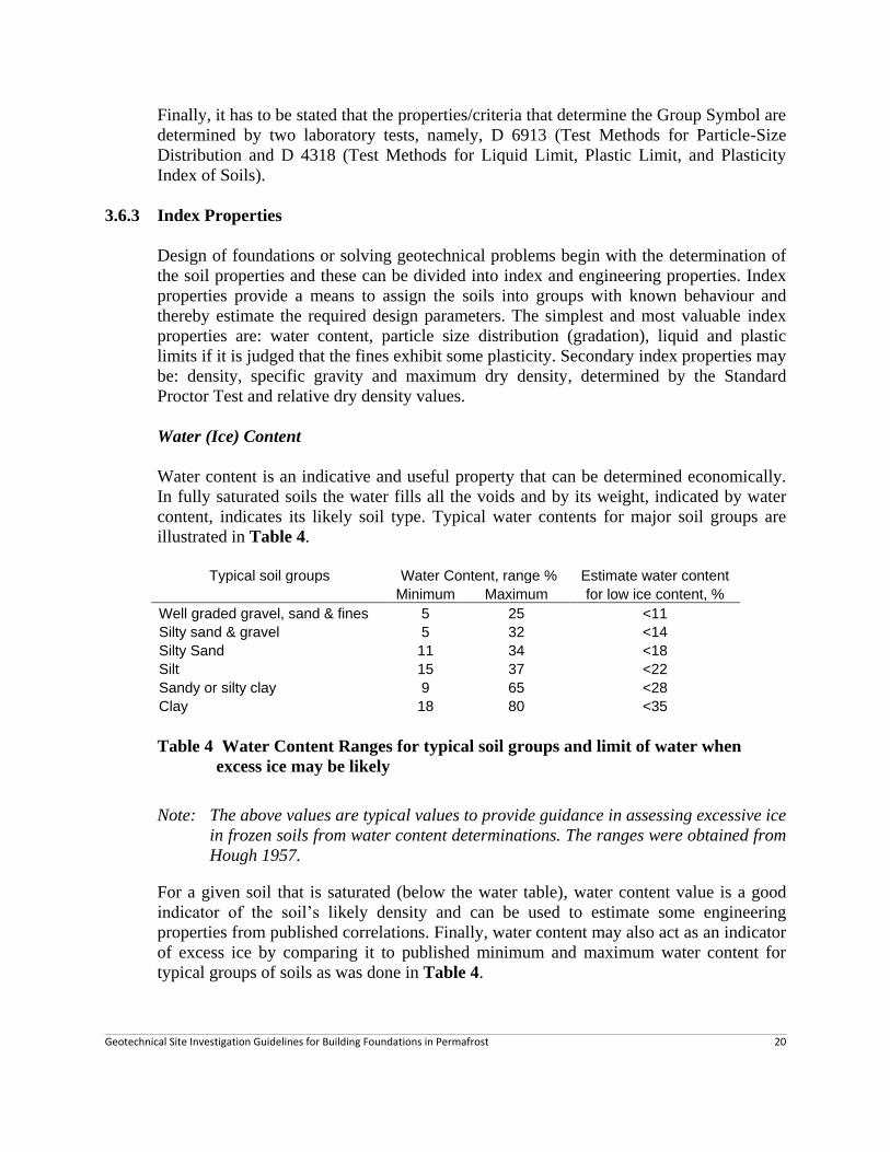
Water (Ice) Content
Water content is an indicative and useful property that can be determined economically.
In fully saturated soils the water fills all the voids and by its weight, indicated by water
content, indicates its likely soil type. Typical water contents for major soil groups are
illustrated in Table 4.
Table 4 Water Content Ranges for typical soil groups and limit of water when
excess ice may be likely
Note: The above values are typical values to provide guidance in assessing excessive ice
in frozen soils from water content determinations. The ranges were obtained from
Hough 1957.
For a given soil that is saturated (below the water table), water content value is a good
indicator of the soil‟s likely density and can be used to estimate some engineering
properties from published correlations. Finally, water content may also act as an indicator
of excess ice by comparing it to published minimum and maximum water content for
typical groups of soils as was done in Table 4.
Typical soil groups Water Content, range % Estimate water content
Minimum Maximum for low ice content, %
Well graded gravel, sand & fines 5 25 <11
Silty sand & gravel 5 32 <14
Silty Sand 11 34 <18
Silt 15 37 <22
Sandy or silty clay 9 65 <28
Clay 18 80 <35

Geotechnical Site Investigation Guidelines for Building Foundations in Permafrost 21
Knowledge of excess ice, as given by water content, in frozen soils is important because
it greatly influences the engineering properties; such as, thaw consolidation (settlement),
creep strength, and thermal properties.
It is recommended that measuring water content from samples should be a dominant part
of a geotechnical site investigation, both in unfrozen and frozen soil regions. (ASTM
D2216).
Particle Size
Particle size and the distribution of particle size determine many of the engineering
properties and also many of the properties of frozen soils. The four variables that
influence the behaviour of unfrozen and frozen soils are:
Coarse or fine grained soils.
Volume of fines within soil matrix.
Distribution of the particle sizes; e.g. poorly or well graded, and
Plasticity of fines.
It is important that particle size analysis tests be conducted on selected samples for the
purpose of correctly classifying the soil of major soil zones at a site. (See Section 3.6.2).
Furthermore, various measurements from the particle size analyses provide means to
estimate engineering properties of the soil. Several particle size distribution test
procedures are given by ASTM. The test to be used depends on the type of soil
encountered.
Liquid and Plastic Limits
Strength and deformation behaviours of frozen and unfrozen fine grained soils are
influenced by their mineralogy. They are grouped into silt and clay soils by their
characteristics that are governed by the mineralogy. Liquid and plastic limits tests
determine the plasticity of fines particles and thereby allow them to be defined as either
silts or clays soils.
It has to be emphasized that a fine grained soil can only be classified correctly as a silt or
clay in the Unified Soil Classification System by determining the liquid or plastic limits if
the fine grained soils exhibit some plasticity.
Salinity
Saline deposits are common near the Arctic Ocean and have been observed as far as 175
km south of the Beaufort Sea (Hivon & Sego 1991). Saline soils are due to continental
and marine deposits affected by sea level changes and sea water saturation (2004).

Geotechnical Site Investigation Guidelines for Building Foundations in Permafrost 22
Soviet investigators (Johnston 1981) define salt content of a frozen soil (salinity) as the
ratio of the weight of salts in the soils to the dry weight of the soil (including the salt)
expressed as a percentage. They consider a frozen soil to be salty by criteria given in
Table 5.
Table 5 Saline Soil Criteria (U.S.S.R. 1973)
Soil Percent of salt
Silty sands 0.05
Fine to coarse and gravelly sands 0.10
Sandy loam 0.15
Clay 0.25
The impact of salinity on the frozen strength of soils is illustrated by Figure 5.
Figure 5 Long-term Strength for Concrete and Marine Sand at -3°C
(Brouchkov 2004)
Other Index Parameters
Other common index parameters that may be determined in the laboratory or estimated
are: specific gravity, dry unit weight and maximum dry density.
3.6.4 Engineering Properties and Parameters
Measuring engineering properties by laboratory and/or field testing is complex and costly
because of variability of ice lensing aside of changes of soil strata and these properties
are dependent on temperature. Since, during the time of laboratory testing, the final long-
term ground temperature has not been established, it is normal to conduct the laboratory
testing at two temperatures that represent the likely range. Because of the complexity and
cost of measuring the engineering properties in the laboratory or in the field, it is
common to derive the engineering design parameters from published field and laboratory
data using index properties established during the field and laboratory testing.

Geotechnical Site Investigation Guidelines for Building Foundations in Permafrost 23
Some engineering properties and parameters that are used in design or evaluation of
foundations and earth structures on permafrost are:
Thaw consolidation (settlement).
Creep Strength at design ground temperature and creep rate.
Adfreeze creep strength at design ground temperatures and creep rate.
Thermal properties for thermal analyses.
The following are brief descriptions of the these properties and the method of testing.
Thaw Consolidation
Time dependent compression resulting from thawing of frozen ground and subsequent
draining of excess water. Thaw consolidation has caused major settlement of early
structures built with heated ground floors on soils with excess ice. But, on the long-term,
thaw may also be produced due to climate warming. Thaw consolidation is determined in
the laboratory by allowing frozen soils cylinders (cores) to thaw. Because ice lensing in
frozen soils is heterogeneous, a large number of frozen core samples have to be taken and
tested.
Creep Strength of Frozen Soil
Instantaneous strength of frozen ice rich soils is high, but in cases of large loading, (such
as end bearing of piles or piers, or large embankments) may result in creep of the ground
that may lead to excessive deformation or failure. Creep strength is defined as the failure
strength of a frozen soil at a given strain or a given period of time under a constant load.
The creep strength is dependent on: soil type, excess ice, temperature and time. The
determination of creep strength requires testing of a number of frozen samples subjected
to a given load at a given temperature over a long period; in terms of weeks.
Adfreeze (creep) Strength
Adfreeze strength is commonly used in the design of piles for buildings in permafrost. It
is defined as the shear strength which has to be overcome to separate two objects that are
bonded together by ice (Everdingen 1998). Adfreeze strength is dependent on the ice
content of soil, the roughness of the object (pile) it adheres to, and temperature.
Adfreeze strength is only a fraction of the creep strength and depends on the „roughness‟
of the perimeter surface of the pile. It increases progressively if the roughness of piles is
increased by: sand blasting of a steel pile, cutting of openings in pile, welding on
protrusions. Determination of adfreeze strength is complex and normally is determined in
pile field load tests. In design of pile foundations adfreeze strength is normally estimated
from published results of laboratory and field tests.

Geotechnical Site Investigation Guidelines for Building Foundations in Permafrost 24
Thermal Properties of Frozen Ground
The properties of the ground governing the flow of heat through it, and its freezing and
thawing conditions (Everdingen 1998). The basic thermal properties of frozen ground are
thermal conductivity, heat capacity and latent heat of fusion.
4.0 DRILLING, SAMPLING AND LABORATORY TESTING
4.1 Drilling Method
Many Northern sites have limited availability of drill equipment and therefore
transporting suitable equipment to obtain the ideal samples and field information must be
carefully considered in obtaining value for expenditure. It is important to select a
geotechnical site investigation that will secure the necessary subsurface information and
minimize the need of requiring a follow-up investigation. The selection of the appropriate
method and equipment depends to a large extent on the experience and judgment of the
geotechnical engineer and the design requirements of the proposed building.
Planning of a geotechnical site investigation at remote sites is a balance between
obtaining complete site information and the cost of the drill methods for obtaining it.
Typical geotechnical site investigation methods/equipment and their capabilities/uses are
summarized in: Table 6.
Some observations on the information given in Table 6 are:
a) Test pits. Test pits provide the most economical means of obtaining subsurface
information. However, they are limited to near surface ground that thaws during
the summer; the greatest thaw depth occurring in August/September. They are
most frequently used to obtain samples of granular construction material.
Test pits conducted with excavators may reach depths of 6 m if the permafrost
consists of organics, frozen clay and some silts at ground temperature >-2C.
Shallow test pits may be sufficient for the structure founded above ground or on
thermosyphons foundation.
b) Auger drills. They are very common in temperature climate regions and are used
in permafrost areas near larger centers and at sites with road access. Transport by
air normally requires Hercules sized aircraft.
Auger drills with solid stem augers are frequently used in the North to obtain
remolded (disturbed) samples from the auger flight. Cylindrical, slightly disturbed
samples may be obtained in fine grained soils with ground temperatures at or
above -5°C using the split spoon sampler.

Geotechnical Site Investigation Guidelines for Building Foundations in Permafrost 25
Hollow stem auger drills allow sampling or coring of the undisturbed frozen
ground through the center of the auger. They are infrequently used in permafrost
because coring requires a fluid and coring in permafrost results in great wear of
the auger stems.
c) Vibratory (sonic) drill. It‟s use is normally limited to unfrozen fine grained soils.
d) Percussion (air-track) drill. This is the most widely used drill in small northern
communities with no road access. This drill pneumatically drives a heavy drill bit
into the rock/frozen ground and blows cuttings to the surface by compressed air
introduced by the hollow steel rods to which the bit is attached.
e) Becker Hammer Drill is a double wall reverse circulation drill with down hole
hammer that allows sampling and coring at the base of the casing. It is efficient in
coarse gravel, rockfill and permafrost. However, it is a large truck mounted drill
that is available only in a few large cities. It is costly to mobilize and therefore it
is rarely used in permafrost regions.
f) Core drill. This is a widely available drill in the North because it is used in
mineral exploration. It is very suitable for taking undisturbed cores of frozen soil.
Normally the coring is done with a double tube N size barrel that produces 54 mm
cores. For best results a salt cooled or refrigerated fluid is used to preserve the
frozen samples.

Geotechnical Site Investigation Guidelines for Building Foundations in Permafrost 26
Table 6. Typical Equipment and Their Capabilities/uses for foundation geotechnical site investigation in permafrost
Method
Approx
Max’m
Depth
m
Material Sample Condition Tests
Fin
e G
rain
ed
Coars
e
Gra
ined
Rock
Th
aw
ed
Fro
zen
Dis
turb
ed
Un
dis
turb
ed
Wate
r
Con
ten
t
Gra
dati
on
&
Pla
stic
ity
En
gin
eerin
g
Typ
e
Gro
un
d
Tem
per
atu
re
Test Pits
Hand excavation 2 X X - X - X - X X - -
Heavy equipment
Dozer 4 X X - X - X - X X - -
Backhoe/excavator 6 X X X X X ? X X - -
Drilling
Auger
Solid stem 15+ X X - X X X - X X - X
Hollow stemB
15+ X X ? X X X X X X ? X
VibratoryC
20 X - - X X X ? X X ? X
Percussion (air-track) 30+ X X X X X X - X X - X
Hammer (Becker) 30+ X X X X X X X X X X X
Core drill – warm fluid 30+ X X X X X X ? X X ? X
Core drill – Cool fluid 30+ X X X X X X X X X X X
From Johnston 1981( Table 5.8, p 204)

Geotechnical Site Investigation Guidelines for Building Foundations in Permafrost 27
4.2 Sampling
Geotechnical site investigation by means of test pits and drilling secures information on
the soil and rock stratigraphy by observation of the test pit and drill hole advance and
collecting samples for laboratory testing. Visual observation of the progress of the
backhoe bucket or the drill rod advance and the disturbed material that comes to the
surface allows visual classification of the permafrost strata and sampling location. In
uniform strata samples are normally taken at about 1.5 m intervals. However, the location
and frequency may be modified when strata changes are observed when engineering
sensitive permafrost conditions are encountered; such as high ice concentration, unfrozen
zone and similar changes of strata.
The type of samples that may be obtained by the various drill methods are given in Table
7. This can be summarized as follows:
Test pits Disturbed or block samples.
Augers Disturbed from auger flight or driven penetration samples from
base of hole.
Vibratory Cylindrical samples that may have little disturbance.
Percussion Continuous frozen soil and ice chips.
Hammer Drill Continuous frozen soil and ice chip with the ability to obtain
driven penetration samples at base of drill rod or core samples.
Core Drill Continuous soil/rock wash material and the ability to obtain driven
penetration samples at base of drill rod or core samples.
Disturbed samples need to be sealed in plastic bags or jars to preserve the water content
after the samples thaw. Frozen soil cores have to be preserved in frozen condition.
4.3 Laboratory Testing and Properties
Laboratory testing entails the establishment of index and engineering properties as
discussed in Section 3.4. Laboratory testing purpose is to quantify the index properties of
the soil and frozen soil encountered and thereby allowing the soils to be classified
according to defined rules. Soils named according to standard classification system have
the same meaning to engineering and construction professionals and can be used to
estimate engineering properties for the design of the foundation.

Geotechnical Site Investigation Guidelines for Building Foundations in Permafrost 28
The design parameters can be obtained either by employing the index properties and
published correlations of these to engineering properties in journals and textbooks or by
measuring the engineering properties directly. However, even if the engineering
properties are measured directly, it is necessary to compare these to the published
engineering properties. To do this latter, it is necessary to relate the measured and
published information by the measured index properties.
4.4 Bedrock
Establishing bedrock for foundation selection or design in permafrost is done for the
purpose of confirming that bedrock surface, and not a large boulder was encountered,
designing of the depth of penetration of a grouted pile in bedrock, or basing the pile
design for end bearing. Normal practice in the investigation of bedrock is to core the
bedrock and secure intact core samples. This is done with 1.5 m long single or double
tube barrels; double tube core barrels are the preferred barrels (they minimize the
disturbance of fractured bedrock cores).
The cores are described by rock types, fracture frequency, orientation and inclusions.
The quality of the intact rock is given by recovery ratio defined as the percentage of the
length of the core recovered and the length of the core drilled on a given run and the Rock
Quality Designation (RQD) which is expressed in percentage as total length of intact
rock pieces of core length greater than 100 mm divided by the total length of drill run.
Breakages caused by drilling are ignored.
Rock quality description based on RQD is given in Table R8.
Table 7 Relation of RQD and In-Situ Rock Quality (Peck et al 1974)
RQD, % Rock Quality
90 – 100 Excellent
75 – 90 Good
50 – 75 Fair
25 – 50 Poor
0 – 25 Very Poor
However, it has to be noted that foundation geotechnical site investigation for small
structures often use air-track drills that do not allow coring of rock. In this case, it is
possible to deduce major soil and rock strata and presence of ice lenses from observations
of the drill rod advance during drilling, and collecting soil particles and rock chips for
further analyses. Water content and particle size analysis laboratory tests permit some
estimate of the possible excess ice and soil classification of the unfrozen soil particles.

Geotechnical Site Investigation Guidelines for Building Foundations in Permafrost 29
5.0 FIELD & LABORATORY PROGRAM
5.1 General
Field investigation programs for building foundation design in permafrost obviously
depend on a large number of variables including: size and complexity of structure,
physiography of the site and existing site information, present and anticipated ground
temperatures at the end of the service life of the structure, availability of test/drill
equipment and project schedule.
A good and efficient program depends greatly on the work done in project definition and
preliminary site and building project evaluation discussed in Chapter 2, and the
experience of the geotechnical consultant. The following provides some guidelines for
the field and laboratory work.
5.2 Test Pits and Drilling
The selection of the field program should be based first on the design requirement of the
proposed structure, the degree of knowledge of the physiographic conditions, and the
availability of drill equipment. The range of field exploration programs includes:
Test Pits – Most frequently used to sample borrow sources but could also be
considered for small buildings to be supported on foundations that will maintain
frozen ground and where good information is available on the local ground, and
foundation performance for similar buildings.
Air-track – Most common drill equipment in northern remote areas. It provides
frozen ground and rock chips for the field geotechnical engineer or technologist to
estimate the likely ground stratigraphy. Visual classification is approximate and
only major strata changes, such as, organics, ice and bedrock distinctly identified.
Water content from thawed samples provides a good indication of soil type and
ice content.
Auger Drill – Auger drill provides continuous remolded material on the auger
wall and allows drive samples at the bottom of the hole if the soil is fine grained
and the ground temperature is above -5°C. Grab samples from the auger spiral
allow improved visual classification of the soil and more representative grab
samples for laboratory testing; as compared to air-track samples.
Rotary and Diamond Drills – Provide the best quality of undisturbed frozen
samples that allow visual observation of ice presence and distribution that can be
used to conduct laboratory testing to establish engineering properties; such as:
thaw settlement, frozen soil creep strength, adfreeze creep strength and thermal
properties.

Geotechnical Site Investigation Guidelines for Building Foundations in Permafrost 30
5.3 Test Hole Depth and Frequency
5.3.1 Test Pits
Test pits are normally conducted in thawed material within the active zone whose
maximum depth occurs during August and September. Maximum thaw depth varies with
the presence of organic cover and water content of the ground. This depth may vary from
1 to 6 m, with likely depth between 1.5 m to 3 m in alluvial and till deposits, and 2 m to 4
m in granular beach, kame and esker deposits.
It is suggested that a minimum of 2 to 3 test pits and representative samples should be
taken at potential granular borrow areas, and 3 to 5 test pits to establish near surface
conditions for small buildings to be supported on permanently frozen foundation.
The purpose of the test pits is to identify poor ground within near surface (2 to 4 m
depth), such as, organic zone and/or poor quality fill, and very loose ground at the base of
the active layer of a high groundwater within a highly permeable thawed gravel zone.
Good ground conditions indicate these do not exist, or if they are present, the
geotechnical engineer will propose a plan of how to deal with these.
5.3.2 Number and Depth of Drill Holes
The number of holes and depths should be planned so that the entire subsurface zone that
may be affected by the load and thermal changes of structure is determined, and
alternative foundation designs could be considered. For a single structure, a minimum of
3 drill holes should be considered. The depth of drill holes may vary and depend on the
number of drill holes planned, likely subsurface conditions and size of the
building/foundations.
In fine grained frozen soils that may have ice lenses, which are potentially ice rich and
may be in a saline environment, drill holes to depths of 15 m to 20 m should be
considered, unless ice-free bedrock is present, and proven, at a shallower depth.
In coarse ground with expected low ice content, 10 to 15 m deep drill holes may be
considered. It is suggested that at least one 15 m deep hole should be drilled for
determining the likely mean annual ground temperature that is represented by the zero
ground temperature fluctuation at about this depth.

Geotechnical Site Investigation Guidelines for Building Foundations in Permafrost 31
5.4 Ground Temperature
Knowledge of the mean annual ground temperature as given at the depth of zero ground
temperature fluctuation, and the estimated likely climate warming rate, is important to
ensure that the designed foundation will function at the end of the service life of the
building. It is recommended that one or two thermistor (temperature sensors) cables be
installed to a depth of 15 to 20 m in the drill holes. The thermistor cables shall have 7 to 8
sensors spaced at increasing distances from the ground surface downward. The thermistor
cable shall be placed within a 25 mm PVC, or other plastic pipe, that is capped at the
bottom and sealed at the surface opening. The pipe does not need to be filled.
Thermistor readings shall be taken after installation and two weeks later to eliminate the
effect of thermal disturbance produced by the drilling. The second set of readings should
represent the in-situ conditions. It is recommended that arrangement be made for the
thermistors to be read on a monthly basis thereafter and the results be processed by the
geotechnical engineer at suitable intervals for one year to obtain the annual ground
temperature fluctuation.
5.5 Classification, Sampling and Laboratory Testing
Important steps in foundation investigations are accurate descriptions and classifications
of the ground, rock and ice content. These are based on a combination of visual
observations during the field drilling and laboratory testing of representative soil samples
collected during the soil investigation to determine the index properties of the unfrozen
soil matrix. The laboratory established index properties allow an accurate soil
classification of the soils.
Visual classification of disturbed and undisturbed samples should be made according to
recognized procedures as summarized in this document and given in detail in ASTM
Standards D40083-89(2007) and D2488-06. Photographs of selected representative
disturbed and undisturbed samples should be taken and provided in the report.
Disturbed and undisturbed samples shall be taken to determine the index and engineering
properties by laboratory testing. Purpose of samples, type and number are given below:
Index Properties
Water Content (Water Content method ASTM D 2216)
Indicates the likely ice content, type of soil, and uniformity of the frozen soil zone.
Samples shall be taken in drill holes at about 1.5 m, or smaller intervals near the surface,
that could be important for the excavation plan and design of the foundation, and placed
in sealed plastic bags for laboratory water content determination. At least two samples
shall be taken from each test pit; preferably from mid depth and bottom of the test pit.

Geotechnical Site Investigation Guidelines for Building Foundations in Permafrost 32
Particle Size Analysis and Liquid and Plastic Limit Tests
These tests are important to classify the encountered thawed soils by recognized criteria
as given in ASTM D2487 and D4318 respectively. It is suggested that at least 3 to 5
representative samples be secured of major ground strata for particle size analysis and
liquid and plastic limit tests.
Salinity
Salinity tests need to be performed on samples obtained from marine or near marine
areas, and inland in areas that were likely inundated by sea water during or after the ice
age. It is suggested that 5 to 8 samples be identified from 2 to 3 drill holes for salinity
testing. Salinity shall be expressed as the ratio (in percent) of the weight of salts in the
soils to the dry weight of the soil (including the salt).
Unit Weights
It is recommended that sufficiently large samples be collected from the air-track cuttings
or auger grab samples to conduct at least one compaction test to establish the maximum
dry density and optimum water content of major and foundation significant soil zones.
Relating water contents from the drill holes to maximum density provide a means to
judge excess water or ice content of the foundation material. Test methods ASTM D698
and D7382 would be suitable for this.
5.5.1 Engineering Properties
The determination of engineering properties by laboratory testing requires frozen core
samples. Great care needs to be exercised to select appropriate sections of the frozen core
and in preserving the frozen state while the core samples are shipped to the laboratory.
There are only a few projects that proceed to determine the engineering properties by
means of laboratory testing because of the effort required to obtain the representative
samples, the number of tests required to cover the likely ranges ice content and
temperature conditions, and complexity and costs of the tests. These tests would likely
only be conducted for large buildings founded on piles within ice rich soil.
The selection of engineering properties for most foundation designs are based on
published information using the index properties of the soils by laboratory tests. The one
exception could be thaw consolidation. This test is relatively simple and can be done at a
reasonable cost. But representative frozen cores are required.

Geotechnical Site Investigation Guidelines for Building Foundations in Permafrost 33
6.0 REPORT OUTLINE
The content of a geotechnical site investigation report depends on the requested terms of
the investigation, the magnitude and complexity of the structure, and the site condition.
Therefore, contents and detail of the reports may vary. The following outline provides a
general table of contents based on literature and the writer‟s experience. It is suggested
the report should be based on:
Structure information/requirements and building engineering design provided by
the architect/design engineer.
Stratigraphy and properties obtained from investigation and laboratory testing
appropriate to the structure requirements and site complexity.
Testing and classification of the soils be based on internationally recognized
standards.
Engineering properties and foundation design requirements to take into
consideration the service life of the proposed structure and the potential impact of
climate warming.
6.1 Introduction
It is suggested that the report be prepared to provide information to the owner,
architect/design engineer and the contractor. As such, the introduction should make
adequate reference to:
The requested terms of reference of the investigation, and
Scope (program) of work provided in fulfilling the requested terms of reference.
The procedure of the geotechnical site investigation could be left for the appendix.
6.2 Background
This chapter provides the physical setting of the project and should include:
Proposed Structure
Detail of the structure guides the extent and detail of investigation. Therefore, it is
necessary that the architect/engineer provide information as given below.
Technical detail of the proposed structure, e.g., single or multi-story, plan
area, above ground, slab-on grade, or with basement.
Service life of the proposed structure; e.g., 30, 50 years or more.
The information could be given in table format as illustrated below:

Geotechnical Site Investigation Guidelines for Building Foundations in Permafrost 34
Table R1 Proposed Structure Information
Item Criteria
Size in plan, m2 and general plan configuration
Single or multi story
Slab-on-ground, above ground, crawlspace/basement, etc
Superstructure design and allowable settlement criteria
Building service life, years
Other
Geological Setting
Overview of the site as provided by geomorphology and bedrock geology obtained from
published information and prior research.
Terrain
Description of surface features of the immediate site that should include: topography,
vegetation and nearby structures.
Hydrology and Immediate Surface Drainage
Water presence and surface flow may influence the design of surface grading and impact
the ground temperatures.
Climate
Present and future climate is an important consideration in the design of foundations in
permafrost. The projected climate warming rate (likely and high) and selected value,
needs to be estimated. This could be given in table(s) as illustrated below.
Table R2 Climate Information
Parameter Project Design Year
(Year)
At End of Building
Service Life (Year)
Mean Annual Air Temperature, °C
Standard Deviation, °C
Freezing Index, C degree days
Thawing Index, C degree days
Precipitation, mm
Snow (equivalent water), mm
Rain, mm

Geotechnical Site Investigation Guidelines for Building Foundations in Permafrost 35
Freezing Index (approximate) – calculated from the mean monthly air temperatures for a specific
station without making corrections for positive degree days (T>0ºC) in spring and fall (Boyd, 1973).
Thawing Index (approximate) calculated from the mean monthly air temperatures for a specific
station without making corrections for negative degree days (T<0ºC) in spring and fall (Boyd, 1973).
Note: Four types of indices have been used; including design indices that are based on the coldest
winter or warmest summers respectively over the last 30 years, if available (Everdingen
1998).
Table R3 Mean Monthly Air Temperature and Precipitation
Item Jan Feb Mar Apr May Jun Jul Aug Sep Oct Nov Dec
Air. °C
Snow, mm
Rain, mm
6.3 Subsurface Conditions
6.3.1 Investigation Program Summary
Includes a description of the method(s) used to assess the ground conditions, equipment
used, number of test holes, dates executed, and laboratory tests conducted. Detailed
description of these should be presented in the Appendix, preceding the field logs and
laboratory testing.
6.3.2 Subsurface Conditions
Description of the major soil and rock formations observed and identification of localized
anomalies observed that could affect the building foundation should be provided. The
description should be based on both visual observations and laboratory tests, and based
on standard soil and permafrost classifications. Each formation should be described under
its own heading and the description should include the mean and range of index
properties, such as water content, major soil fractions (especially fines content), and
salinity.

Geotechnical Site Investigation Guidelines for Building Foundations in Permafrost 36
The subsurface conditions should be summarized in a table as illustrated below for an
easy overview.
Table R4 Illustrative Soil Strata Summary
Strata
Soil Group
Depth in
meters
Classification
Symbols Water
Content,
%
Salinity,
% Soil Permafrost
Fill – Crushed minus 20 mm 0 – 0.5 GP 8 NA
Peat, fibrous 0.5 – 1.5 Pt Vr 250 NA
Sand
(Poorly graded sand with silt) 1.5 – 6.0 SP-SM Vx/Vs 25 25
Silty Sand
(Silty sand with gravel) 6.0 – 15.0 SM Vx 13 20
Note: Classification symbols should be based on ASTM D2487 and D4083 that assign the
symbols by prescribed percentage ranges of soil groups and plasticity, when applicable.
6.3.3 Ground Thermal Regime (Ground Temperature)
The ground thermal regime should be represented by the actual ground temperature
measured in the field, and estimation of the likely ground temperatures at end of
construction and the end of the service life of the building. The depth of the annual thaw
(active layer) has to consider any changes to the vegetation ground cover, removal and
replacement of existing peat layer or other organic zones, and shading and heating effects
created by the structure. The mean annual ground temperature should be reported at 15 m
depth, normally the depth at which little or no ground temperature fluctuation occurs.
Ground temperature profiles should be presented in the Appendix.
Ground temperatures at the time of investigation, and the likely range of values at the end
of the structure service life, should be provided in a table as illustrated for Inuvik in
Table R3.
Table R5 Typical Ground Temperature Information
Parameter Study Year
2008
Likely range at end of
structure design life
(2060)
Mean annual ground temperature at 15m depth, °C -2.4 -0.3 to +1
Mean annual thaw depth, with existing peat, m 1.5 Annual frost
Mean annual thaw depth, peat removed /m 2.5 Annual frost

Geotechnical Site Investigation Guidelines for Building Foundations in Permafrost 37
The above example displays a suggested range of ground information based on a mean
annual air temperature warming rate of 6 to 10 degrees per 100 years. The mean annual
thaw depth is difficult to predict because it greatly depends on the latent heat of fusion of
the frozen zone. Depth and type of organic zone and amount of ice content within the soil
have a great bearing on the thaw depth for a given summer air temperature profile.
6.3.4 Construction Materials
The report should identify all possible earth construction materials that include,
a) granular form esker, kames and beaches;
b) bedrock for quarries, and
c) native soil.
The report should provide index properties of these materials and likely quantities
available.
6.3.5 Design Properties and Criteria
The geotechnical engineer may consider summarizing the most relevant site conditions
and design criteria on one, or at most, two sheets. The summary sheet(s) would provide
an easy overview of the important building design criteria, climate and ground
information, geotechnical and thermal properties and engineering design properties.
6.4 Design Recommendations
6.4.1 Foundation Design and Alternatives
The report should recommend the optimal foundation design suitable for the established
frozen ground conditions and the structure criteria. It should comment on:
Recommended foundation design (granular pad with air space, piles or
thermosyphons).
Pile adfreeze strength including design ground temperature.
Likely uniform and differential settlement over the service life of the structure.
The report should suggest any other viable foundation design(s) and address the positives
and negatives of the recommended and the alternative foundation designs.

Geotechnical Site Investigation Guidelines for Building Foundations in Permafrost 38
6.4.2 Site and Construction Material Preparation
The report should summarize the required site preparation to construct the foundation.
This may include: surface water control, organic layer removal, work pad etc.
Furthermore, the near surface ground conditions change through the summer months
when most site work is done, and therefore an optimal site preparation schedule should
be given.
6.4.3 Grading
Foundations that depend on frozen ground may be impacted by surface and ground water
flows and ponded water during the summer. The report should provide guidance for
grading around the structure and the management of seasonal surface and ground water.
6.4.4 Construction Aspects and Schedules
The report should provide comments and guidance on the above. Detailed material
specifications will be prepared in a foundation design report.
The site investigation report should comment on site issues that may impact on the
selection and design of the foundations, such as: excavation of peat and surface ice rich
soils, dewatering of the excavation, re-use of the excavated inorganic thawed ground for
backfill, and/or other issues. It should also provide months for greatest thaw depth for
ease of excavation, and month by which the earthwork should be completed by.
6.5 Conclusions
Highlight of the key findings and recommendations.
6.6 Limitations of the Investigation
The geotechnical consultant may state the practical and legal limitation of the
geotechnical site investigation and the derived information. This typically contains a
limitation in use and reliance to the organization for which the report was prepared
(client).

Geotechnical Site Investigation Guidelines for Building Foundations in Permafrost 39
6.7 APPENDICES
6.7.1 TEXT
A - Classification Tables, Figures & Charts
B - Geotechnical Site Investigation Procedure
6.7.2 GRAPHICS & DATA
C - Site Location Map
Detailed Plan with contours, existing structures & water bodies
D - Photographs (Site, exploration equipment & typical materials from samples)
E - Stratigraphic and Geotechnical Profiles (if applicable)
F - Boring Logs with all necessary pertinent information on soil, rock and groundwater
G - Ground Temperature Profiles
H - Laboratory Data & Graphs

Geotechnical Site Investigation Guidelines for Building Foundations in Permafrost 40
7.0 Selected ASTM International Standards
ASTM Standards are developed and maintained by ASTM Internationals that evolved
from the American Society for Testing Materials. The standards are produced by
committees of experts and provide a guide in the classification and testing of materials.
The standards are identified by designation and their titles.
The first four standards listed below provide the base of much of these guidelines. They
provide the following:
ASTM D 420 - Standard Guide to Site Characterization for Engineering Design and
Construction Purpose
This standard was developed for the guidance of geotechnical site investigation in
non-permafrost areas. While it does not address permafrost and its characteristics,
it provides a great amount of information that is applicable also to permafrost.
The guide does not include foundation design in permafrost nor the most recent
impact of climate warming on permafrost, and therefore, how this should be taken
into consideration in the design of building foundations in permafrost.
ASTM D 4083 - Description of Frozen Soils (Visual-Manual Procedure)
This standard provides guidelines on the description of frozen soils (permafrost).
ASTM D 2487 - Standard Practice for Classification of Soils for Engineering Purposes
(Unified Soil Classification System)
The Unified Soil Classification System provides rules for categorizing unfrozen
soils into groups with common characteristics and show similar behaviour. The
classification is based on the results on laboratory test results and therefore on
defined criteria. While the classification is for unfrozen soil, the properties and
characteristics of an unfrozen zone influence the engineering properties of frozen
soils.
ASTM D 2488 - Practice for Description and Identification of Soils
(Visual-Manual Procedure)
This is a companion standard to ASTM 2487. It provides a guideline to describe
the soil based on visual observations. It extends the ASTM 2487 in that it
describes for instance the angularity of gravels etc. Again it was developed for
unfrozen soils but it is also useful for frozen soils.
The remaining Standards provide guidelines for conducting laboratory tests and
method for classifying and testing peat. These tests are given for reference
reasons.

Geotechnical Site Investigation Guidelines for Building Foundations in Permafrost 41
Standard ASTM
Designation Title
Guidelines
D420 – 98 (2003) Standard Guide to Site Characterization for Engineering Design and
Construction Purpose
D4083 – 89(2007) Description of Frozen Soils (Visual-Manual Procedure)
D2487 – 06 Standard Practice for Classification of Soils for Engineering Purposes
(Unified Soil Classification System)
D2488 – 06 Practice for Description and Identification of Soils (Visual-Manual
Procedure)
Reference Documents
(Employed by geotechnical engineers but not included in this document. They are applicable
to laboratory testing of unfrozen soils).
C117 Test Method for Materials Finer than 75-μm (No.200) Sieve in Mineral
Aggregates by Washing
C136 Test Method for Sieve Analysis of Fine and Coarse Aggregates
C702 Practice for Reducing Samples of Aggregate to Testing Size
D422 Test Method for Particle-Size Analysis of Soils
D1140 Test Methods for Amount of Material in Soils Finer than No. 200 (75-
μm) Sieve
D2216 Test Methods for Laboratory Determination of Water (Moisture)
Content of Soil and Rock by Mass
D2217 Practice for Wet Preparation of Soil Samples for Particle-Size Analysis
and Determination of Soil Constants
D2607 Classification of Peats, Mosses, Humus and Related Products
D4318 Test Methods for Liquid Limit, Plastic Limit and Plasticity Index of
Soils
D4427 Classification of Peat Samples by Laboratory Testing
D6913 Test Methods for Particle-Size Distribution (Gradation) of Soils Using
Sieve Analysis
D698 – 00 Standard Test Methods for Laboratory Compaction Characteristics of
Soil Using Standard Effort (12,400 ft-lbf/ft3 (600 kN-m/m
3)
D7382 – 07
Standard Test Methods for Determination of Maximum Dry Unit
Weight and Water Content for Effective Compaction of Granular Soils
Using Vibratory Hammer.

Geotechnical Site Investigation Guidelines for Building Foundations in Permafrost 42
8.0 REFERENCES
AMEC Earth & Environmental, 2008. Geotechnical investigation, foundation rehabilitation
(draft), Western Arctic Regional Visitor Centre, Inuvik, NT. To A.D. Williams
Engineering Inc. Aug 2008
Andersland, O.B. and Ladanyi, B. 2004. Frozen Ground Engineering, 2nd Edition. John Wiley &
Sons
ASTM International Standards. Various standards.
Brouchkov, B. 2004. Construction on frozen saline grounds of the Arctic Coast of Eurasia.
http://www.netpilot.ca/geocryology/files
CGS 2006. Canadian Foundation Manual, 4th Edition. The Canadian Geotechnical Society c/o
BiTech Publisher Ltd.
EC climate warming scenarios.
http://www.ccsn.ca/scenarious/seasonal_maps_CRM4.2.0.html
Environment Canada, 2008. Climate Data Online
Everdingen, Robert van, ed. 1998. Revised January 2002. Multi-language Glossary of Permafrost
and Related Ground-Ice Terms. In International Permafrost Association Standing
Committee on Data Information and Communication (comp.)' 2003.
Golder Associates & J.F. MacLaren 1976. Tunneling Technology, an appraisal of the state of the
art for application to transit systems. Published by Ministry of Transportation and
Communication, Ontario.
Hivon, E.G. and Sego, D.C. 1993. Distribution of Saline Permafrost in the Northwest Territories,
Canada. Cdn Geotechnical Journal, 30, pp 506-514.
Hough. B.K., 1957. Basic Soils Engineering. The Ronald Press Company.
Holubec, Igor. 2007. Design requirements for climate warming in permafrost. Yellowknife 2007
Symposium. Canadian National Committee for the International Permafrost Association.
May 2007.
Johnston, G.H., 1981. Permafrost, engineering design and construction. National Research
Council of Canada, John Wiley & Sons, 1981. 483 p.
National Resources Canada. From impacts to adaptation: Canada in a changing climate 2007.
http://adaptation.nrcan.gc.ca/2007/index-e.php
NRC 2008. Significant earthquakes and seismic hazards.
http://atlas.nrcan.gc.ca/site/maps/environment/naturalhazards/earthquakes
Smith, S. and Burgess, M., 2000. Ground Temperatures Database for Northern Canada.
Geological Survey of Canada Open File Report 3954. 27 p.
US Army & Air Force, 1983. Arctic and Subarctic Construction Foundations for Structures.
Published by the U.S.A. Dept of the Army and the Air Force, October 1983.

Geotechnical Site Investigation Guidelines for Building Foundations in Permafrost 43
9.0 APPENDIX
Tables and a figure providing guidance for describing and classifying frozen ground
and unfrozen soils. Based on ASTM International Standards.
Table A 1 Ground Ice Symbols and Description........................................................ 44
Table A 2 Unfrozen Soil Classification...................................................................... 46
Table A 3 Unified Soil Classification System ............................................................ 47
Figure A 1 Schematic Description of Ice Inclusions .................................................. 45
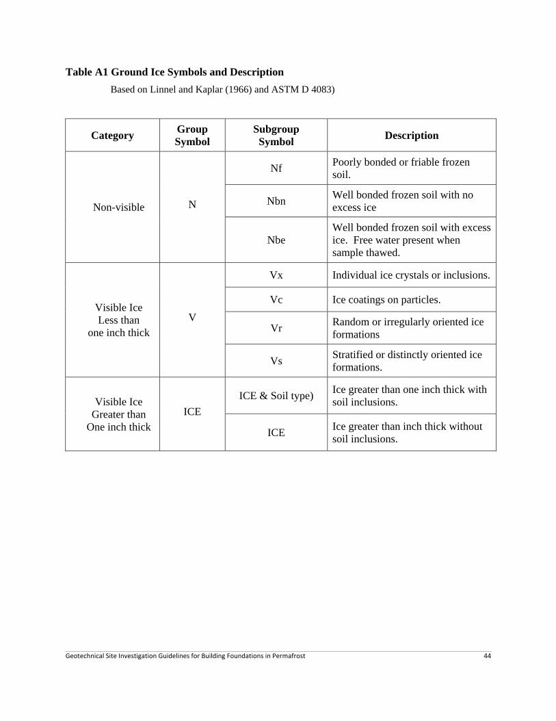
Geotechnical Site Investigation Guidelines for Building Foundations in Permafrost 44
Table A1 Ground Ice Symbols and Description
Based on Linnel and Kaplar (1966) and ASTM D 4083)
Category Group
Symbol
Subgroup
Symbol Description
Non-visible N
Nf Poorly bonded or friable frozen
soil.
Nbn Well bonded frozen soil with no
excess ice
Nbe
Well bonded frozen soil with excess
ice. Free water present when
sample thawed.
Visible Ice
Less than
one inch thick
V
Vx Individual ice crystals or inclusions.
Vc Ice coatings on particles.
Vr Random or irregularly oriented ice
formations
Vs Stratified or distinctly oriented ice
formations.
Visible Ice
Greater than
One inch thick
ICE
ICE & Soil type) Ice greater than one inch thick with
soil inclusions.
ICE Ice greater than inch thick without
soil inclusions.

Geotechnical Site Investigation Guidelines for Building Foundations in Permafrost 45
Figure A1 Schematic Description of Ice Inclusions (See subsection 3.5.1)
Based on Linnel and Kaplar (1966) and ASTM D 4083)

Geotechnical Site Investigation Guidelines for Building Foundations in Permafrost 46
Table A2 Unfrozen Soil Classification
Visual Identification of Soils; Definitions of Soil Components and Fractions
1. Particle Sizes
Material Fraction Sieve Size
Boulders Plus 300 mm Plus 12 in.
Cobbles 75 – 300 mm 3 – 12 in.
Gravel Coarse 19 – 75 mm ¾ – 3 in.
Fine 4.76 – 19 mm No. 4 to ¾ in.
Sand Coarse 2.0 – 4.76 mm No. 10 – No. 4
Medium 0.42 – 2.00 mm No. 40 to No. 10
Fine 0.074 – 0.42 mm No. 200 – No. 40
Fines (Silts & clays) Passing 0.0074 mm Passing No. 200
2. Coarse- and Fine Sized Soils (After Department of the Navy 1983)
Description Percentage Requirements
trace 1 – 10
little 10 – 20
some 20 – 35
and 35 – 50

Geotechnical Site Investigation Guidelines for Building Foundations in Permafrost 47
Table A3 Unified Soil Classification System
(Based on ASTM Designation D 2487 – 06 Unified Soil Classification System
GROUP NAME
Criteria for assigning Group Names and Group Symbols
Soil Classification
Group Symbol with Generalized
Group Description
GW Well-graded Gravels Clean GRAVELS
Less than 5% fines GP Poorly-graded Gravels
GM Gravel & Silt Mixtures
GRAVELS
50% or more of
coarse fraction
retained on No. 4
sieve
GRAVELS with fines
More than 12% fines GC Gravel & Clay Mixtures
SW Well-graded Sands Clean SANDS
Less than 5% fines SP Poorly-graded Sands
SM Sand & Silt Mixtures
COARSE-
GRAINED
more than 50%
retained on No. 200
sieve SANDS
More than 50% of
coarse fraction
passes No.4 sieve
SANDS with fines
More than 12% fines SC Sand & Clay Mixtures
ML Non-plastic &
Low-plasticity Silts INORGANIC
CL Low-plasticity Clays SILTS AND CLAYS
Liquid limit 50% or
less
ORGANIC OL
Non-plastic &
Low-plasticity organic Clays
Non-plastic &
Low-plasticity organic Silts
CH High-plasticity Clays INORGANIC
MH High-plasticity Silts
FINE GRAINED
SOILS
50% or more passes
the No. 200 sieve
SILTS AND CLAYS
Liquid limit greater
than 50% ORGANIC OH
High-plasticity organic Clays
High-plasticity organic Silts
HIGHLY
ORGANICE
SOILS
Primarily organic matter, dark in color, and
organic odour PT Peat
Plasticity Chart
0
10
20
30
40
50
60
0 10 20 30 40 50 60 70 80 90 100
Liquid Limit, %
Pla
sti
cit
y, %
ML or OL
OH
or
MH
OH or MH
CL or OL
CL or ML
ML or OL
“U” Lin
e
“A” Line
0
10
20
30
40
50
60
0 10 20 30 40 50 60 70 80 90 100
Liquid Limit, %
Pla
sti
cit
y, %
ML or OL
OH
or
MH
OH or MH
CL or OL
CL or ML
ML or OL
“U” Lin
e
“A” Line

Geotechnical Site Investigation Guidelines for Building Foundations in Permafrost 48
Explanations:
First and/or second letters Second letter
Letter Definition Letter Definition
G gravel W Well graded (diversified particles sizes)
S sand P Poorly graded (uniform particle sizes)
M silt L Low plasticity
C clay H High plasticity
O organic
Pt peat
Notes: Gravels and sands may be described by two sets of symbols if they contain between 5 to
12% of fines (clay or silt). Also a low plasticity clay may be described by a combined
symbol of CL-ML. See ASTM D 2487-06 for detail.
Well and poorly graded soils are based on coefficients of curvature (Cc) and the uniformity that
coefficient (Cu) are determined from ratios of particle sizes corresponding to the cumulative
particle-size distribution curve. See ASTM D 2487-06 for detail.
Silt and clay are identified by liquid and plastic limits of the fines and plotted on a plasticity
chart. See ASTM D 2487-06 for detail.