gestra steam systems · gestra steam systems en english. 2 ... troubleshooting ... equipment module...
TRANSCRIPT

1
ORGS 111ORGS 112Installation & Operating Instructions 81080105Oil Detector & Alarm ORGS 11-1, ORGS 11-2
GESTRA Steam Systems
ENEnglish

2
ContentsPage
Important notes
Usage for the intended purpose ...............................................................................................................4Function ..................................................................................................................................................4Safety note ..............................................................................................................................................4
Directives and standards
Approvals for Marine Applications ...........................................................................................................5LV (Low Voltage) Directive and EMC (Electromagnetic Compatibility) ........................................................5ATEX (Atmosphère Explosible) .................................................................................................................5Note on the Declaration of Conformity / Manufacturer's Declaration ...................................................5Design ....................................................................................................................................................5
Technical data
ORGS 11-2 ..............................................................................................................................................6Name plate/marking ...............................................................................................................................8
Installation
Installation requirements .........................................................................................................................9Examples of installation ........................................................................................................................10Dimensions ORGS 11-1 .........................................................................................................................11Key .......................................................................................................................................................11Dimensions ORGS 11-2 .........................................................................................................................12ORGS 11-2 ............................................................................................................................................13Tools .....................................................................................................................................................13Key .......................................................................................................................................................13
Electrical connection
ORGS 11-1 ............................................................................................................................................14Connection of measuring electrode ORGS 11-1 .....................................................................................15Connecting ORGS 11-1 ........................................................................................................................15Key .......................................................................................................................................................15Tools .....................................................................................................................................................15Wiring diagram for oil detector & alarm ORGS 11-1 ...............................................................................16Connecting oil detector & alarm ORGS 11-1 with supply voltage 24 / 115 / 230 V AC ............................16
Basic settings
Factory setting ......................................................................................................................................17Selecting the measuring range ..............................................................................................................17

3
Contents Page
continued
Commissioning procedure
Applying supply voltage.........................................................................................................................18Operating valves ...................................................................................................................................18
Operation
Normal operation, oil alarm ...................................................................................................................18
Troubleshooting
Safety note ............................................................................................................................................19Indication, diagnosis and remedy ..........................................................................................................19Exchanging the electronic module .........................................................................................................20Spare parts list ......................................................................................................................................20
Removing and disposing of measuring electrode ORGS 111
Safety note ............................................................................................................................................21Removing and disposing of measuring electrode ORGS 11-1.................................................................21

4
Function
The oil detector & alarm ORGS 112 is an equipment unit consisting of the measuring electrode ORGS 11-1 and a measuring pot. The measuring electrode ORGS 11-1 is a compact-type system that comprises the measuring electrode and an electronic module integrated in the terminal box. The electrode operation is based on the conductive measuring principle using the electrical conductivity of the water for signalling water level. The electronic module detects whether the electrode rods are submerged or exposed and, in the event of ingress of oil, deactivates the output contacts. A water sample, taken from the cooling water system downstream of the location at the highest point where ingress of oil might occur, is fed from below into the measuring pot of the ORGS 11-2. If the water is contaminated with oil, the oil droplets - due to their lower density - ascend and accumulate on top of the water and, consequently, the electrode rods are now submerged in this oil film. Oil is not electrically conductive, which means that no current can flow between the electrode rods of the measuring electrode. In this case the oil detector & alarm will signal ingress of oil and trigger an alarm. The amount of oil necessary to signal ingress of oil depends on the design of the measuring pot and the length of the electrode rods. The measuring pot is matched to the electrode such that ingress of oil is signalled when the oil content limit of approx. 50 ml is reached. The equipment can detect all substances that are insoluble in water, not emulsified and lighter than water. In addition, the equipment can also detect all liquids with a conductivity value below the adjusted response sensitivity.
Important notes
Usage for the intended purpose
Use oil detector & alarm ORGS 11-2 only for signalling ingress of oil in cooling water systems.
Safety note
Danger
When loosening the measuring electrodes hot cooling water may escape.This presents the risk of severe scalding all over the body!Do not remove the measuring electrode ORGS 11-1 unless the boiler pressure is verified to be zero.The terminal strip of the measuring electrode ORGS 11-1 is live during operation! This presents the danger of electric shock!Cut off power supply before mounting or removing the housing cover!
The equipment must only be installed and commissioned by qualified and competent staff. Retrofitting and maintenance work must only be performed by qualified staff who - through adequate training - have achieved a recognised level of competence.
Attention
The name plate specifies the technical features of the equipment. Do not commission or operate any item of equipment that does not bear its specific name plate.
5
Design
ORGS 112:Equipment module with three isolating valves and rapid-action deaerator, ready for connection. Fig. 5
ORGS 111 :Measuring electrode as spare part for equipment module ORGS 11-2 Fig. 4
Attention
Rust preventing oils, which are for instance emulsified in the cooling water, will not raise an alarm!
Directives and standards
Approvals for Marine Applications
The equipment is approved for marine applications.
ATEX (Atmosphère Explosible)
According to the European Directive 2014/34/EU the equipment must not be used in explosion-risk areas.
Note on the Declaration of Conformity / Manufacturer's Declaration
For details on the conformity of our equipment according to the European Directives see our Declaration of Conformity or our Declaration of Manufacturer.The current Declaration of Conformity / Declaration of Manufacturer are available in the Internet under www.gestra.de documents or can be requested from us.
LV (Low Voltage) Directive and EMC (Electromagnetic Compatibility)
The equipment meets the requirements of the Low Voltage Directive 2014/35/EU and the EMC Directive 2014/30/EU.

6
ORGS 112
Technical data
Oil detector & alarm ORGS 112 (equipment unit)Service pressure 6 barService temperature 110 °CFlow velocity 100 l/h to 300 l/h, recommended 200 l/hPressure drop ∆pv 0.06 bar (under test conditions)Alarm Raised when approx. 50 ml oil has accumulatedWater inlet, drain Ball valve with EO-connection 15 LWater outlet Ball valve with EO-connection 12 LWeight approx. 7.4 kg
Measuring electrode ORGS 111 (component of ORGS 11-2)Mechanical connection Screwed G 1 A, ISO 228Materials Screw-in body: 1.4571, X6CrNiMoTi17-12-2 Electrode rods: 1.4571, X6CrNiMoTi17-12-2 Insulating sheath: PTFE Terminal box: 3.2161 G AlSi8Cu3Supply voltage230 V +/- 10 %, 50/60 Hz115 V +/- 10 %, 50/60 Hz24 V +/- 10 %, 50/60 Hz (optional)Power consumption 5 VAFuse external slow-blow 0.5 A internal thermal fuse Tmax = 102 °CResponse sensitivity Range 1: 10 µS/cm Range 2: 0.5 μS/cm Code-switch selectableElectrode voltage 10 Vpp

7
ORGS 111
Outputs for control circuit 2 volt-free change-over contacts, 8 A 250 V AC / 30 V DC cos ϕ = 1 De-energizing delay: 3 sec. Provide inductive loads with RC combinations according to manufacturer's specification to ensure interference suppression.
Indicators and adjusters 2 red LEDs indicating "Electrode submerged" and "Output relay energized" (no ingress of oil) 1 four-pole code switch for selecting the response sensitivity
Electrical connection 2 cable gland with integrated cable clamp M20 x 1.5 1 five-pole screw-type terminal strip, detachable, conductor size 1.5 mm2
Protection IP 65 to DIN EN 60529
Max. admissible ambient temperature Max. 70 °C
Storage and transport temperature – 40 up to + 80 °CCertificationMarine applications BV 17515-B0 BV
GL 17106-00 HH; LR 07-20031 (E1)
Technical data
Scope of supply
ORGS 112 1 Oil detector & alarm ORGS 11-2, PN 6 1 Measuring electrode ORGS 11-1 (mounted) 2 Sealing plugs for cable entry 1 Installation manual
continued
continued

8
GL 17106-00HH
Technical data
Name plate/marking
Fig. 1
Equipment designation
Pressure rating, End connection, Material number
Pressure/temperature range
CE Marking
Spare part specification
Safety note
Disposal note
Power rating
Type approval no.
Manufacturer
continued

9
Installation
Installation requirements
The water sample taken from the cooling water system must flow continuously through the oil detector & alarm ORGS 11-2. We recommend a flowrate of 200 l/h.The sampling of the cooling water should take place downstream of a potential oil leak at the highest point and, if possible, in a horizontal line. Since the oil flows in the upper part of the pipe we recommend the installation of a welding saddle according to DIN 2618 for collecting the oil droplets. The line leading to the measuring pot of the ORGS 11-2 should be vertically ascending, running directly into the bottom part of the measuring pot. Avoid any narrow parts in the supply line since they could give rise to undesired emulsification of the oil.If space is a consideration and the measuring pot has to be installed at a lower point than the main cooling line make sure that the line leading to the measuring pot features sufficiently sized bends in order to prevent emulsification.To achieve the recommended flowrate of approx. 200 l/h provide the main cooling water line with a standard orifice plate in order to throttle the flow velocity between the water sampling location and its re-entry point.The pressure drop ∆pv across the measuring pot is 0.06 bar.The pressure drops of the connecting lines depend on the design and layout of the installation and must be ascertained individually. The calculated resistance coefficient ζ can be used to determine the opening ratio and, consequently, the required diameter "d" for the opening of the standard orifice plate.For more information on the sizing and layout of fluid dynamic systems please refer to the corresponding technical literature and relevant standards.

10
Examples of installation
Installation
Cooling water cycle
Cooling water cycle
2
3
8
4
9
7
1
56
2
3
8
49
7
1
5
6
Fig. 3
Fig. 2
continued

11
Installation
Key
1 Oil detector & alarm ORGS 11-2 (equipment unit)
2 Automatic rapid-action deaerator
3 Cooling water outlet (ball valve DN 12 L, PN 500)
4 Drain (ball valve DN 15 L, PN 500)
5 Cooling water inlet (ball valve DN 15 L, PN 500)
Dimensions ORGS 111
GESTRA Steam Systems
GESTRA
Fig. 4
∅ 42
336
173
G1 AISO 228
9650
15
140
b = 70
6 Cooling water inlet DN 15 (outside ∅ 20 mm)
7 Standard orifice plate
8 Cooling water outlet DN 12 (outside ∅ 16 mm)
9 Main engine, diesel fuel, oil cooler, etc.
continued

12
Dimensions ORGS 112
Installation
Fig. 5
a
85
~84
5
~68
5
0
60
8.5
45
15
23
R 8
5990
331
f
e
5
d
a
~ 160
cb
8
11
270
45
70
19210
a
continued
13
Installation
Key
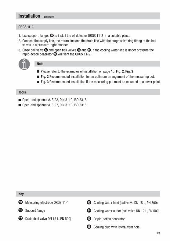
0 Measuring electrode ORGS 11-1
a Support flange
b Drain (ball valve DN 15 L, PN 500)
c Cooling water inlet (ball valve DN 15 L, PN 500)
d Cooling water outlet (ball valve DN 12 L, PN 500)
e Rapid-action deaerator
f Sealing plug with lateral vent hole
1. Use support flanges a to install the oil detector ORGS 11-2 in a suitable place.2. Connect the supply line, the return line and the drain line with the progressive ring fitting of the ball
valves in a pressure-tight manner.3. Close ball valve b and open ball valves c and d. If the cooling water line is under pressure the
rapid-action deaerator e will vent the ORGS 11-2.
Note
Please refer to the examples of installation on page 10, Fig. 2, Fig. 3 Fig. 2 Recommended installation for an optimum arrangement of the measuring pot. Fig. 3 Recommended installation if the measuring pot must be mounted at a lower point
Tools
Open-end spanner A. F. 22, DIN 3110, ISO 3318 Open-end spanner A. F. 27, DIN 3110, ISO 3318
ORGS 112
continued

14
1 2 3 4 5 6 7 8 9 10 11 12 13 14 15
10µS/cm
0,5µS/cm
ORGS 111
Electrical connection
GESTRA Steam Systems
GESTRA
Fig. 6
Fig. 7
g i h
k
n
lj
op q
r
s
i
t
u
m

15
A self-locking fixing nut j connects the terminal box to the electrode part. Before establishing the electrical connection you can turn the terminal box through max. +/– 180° into the desired direction (cable gland).
Electrical connection
Tools
Screwdriver, size 1 Screwdriver, size 2.5, completely insulated according to DIN VDE 0680-1
Connection of measuring electrode ORGS 111
1. Unscrew cover screws g and remove cover h. Fig. 6 2. Detach terminal strip n from circuit board. 3. Strip off approx. 40 mm of cable insulation coating and remove approx. 5 mm of conductor end
insulation. 4. Loosen cable glands i. If the equipment is supplied with 24 V pull control cable through one of the
cable glands. Seal off the unused cable gland (protection IP 65). If the equipment is supplied with 115 / 230 V pull the power cable through the right cable gland and the control cable through the left.
5. Connect the individual cables according to the wiring diagram to the terminal strip n. 6. Re-attach terminal strip n to circuit board. 7. Tighten cable glands i. 7. Mount cover h and fasten cover screws g.
Connecting ORGS 111
Attention
The following relocations of cables with basic insulation are not permissible: Mains and control cables in low voltage areas.
g Cover screws (cross recess head screws M4)
h Body cover
i Cable glands M 20 x 1.5
j Fixing nut for terminal box
k Thermal fuse TMAX 102 °C
l Terminal strip for thermal fuse
m Connection of functional earth
n Terminal strip
o LED "Oil alarm"
p LED "Oil alarm"
q LED without function
r LED without function
s Code switch for measuring range
t Fixing screws for electronic module (4x)
u Electronic module
Key
continued

16
Wiring diagram for oil detector & alarm ORGS 111
Fig. 8 Relays shown in power-off (alarm) position, LEDs 1 and 2 not illuminated!
1
N L L
Oil
Alarm
230(24)V
115V
Netz
Main
Secteur
Red
PE
2 3 4 5 6 7 8 9
10µS/cm
0,5µS/cm
21
1
Alarm
T
2
1 2 3 4
ON
Electrical connection
Connecting oil detector & alarm ORGS 111 with supply voltage 24 / 115 / 230 V AC
Provide the oil detector & alarm with an external slow-blow fuse 0.5 A. To connect the supply voltage and the output contacts use multi-core control cables with a min. conductor size 1.5 mm2, e. g. LiYCY .. x 1.5 mm2.
continued

17
The measuring range can be switch-selected between ≥ 0.5 µS/cm and ≥ 10 µS/cm by means of a code switch s (toggle switch white):
1. Undo the cover screws g and take off the housing cover h. Fig. 6
Code switch 1 – 4 OFF Measuring range ≥ 0.5 µS/cm.
Code switch 1 – 4 ON Measuring range ≥ 10 µS/cm.
2. Mount cover h and fasten cover screws g.
Basic settings
Factory setting
The oil detector & alarm features the following factory set default values: Measuring range ≥ 10 µS/cm
Selecting the measuring range
Attention
Do not damage the electronic components when setting the code switch! Do not use a pencil to set the code switch!
831632

18
3. Close ball valve b and open ball valves c and d. If the cooling water line is under pressure the rapid-action deaerator e will vent the ORGS 11-2.
4. If the measuring pot is vented and completely filled with cooling water the red LEDs f and g are illuminated.
5. Mount cover h and fasten cover screws g.
Operating valves
Operation
Normal operation, oil alarm
1. Under certain conditions air or gases that have been dissolved in the cooling water can accumulate in the upper part of the measuring pot. The rapid-action deaerator e will automatically vent the measuring pot during normal operation.
2. If oil accumulates in the upper part of the measuring pot and the electrode rods of the measuring electrode are completely covered with oil, an oil alarm will be raised and the LEDs o and p extinguish.
3. If an oil alarm has been triggered although there is no oil in the cooling water system, please refer to the troubleshooting notes on page 19.
Commissioning procedure
Danger
The terminal strip of the oil detector & alarm is live during operation.This presents the danger of electric shock!Cut off power supply before mounting or removing the housing cover!Use only a completely insulated screwdriver according to VDE 0680 for setting the measuring points.
1. Unscrew cover screws g and remove cover h. Fig. 62. Please check that the oil detector & alarm is wired in accordance with the wiring diagram
(Fig. 8 page 16) and switch on mains voltage.
Applying supply voltage
19
Troubleshooting
Attention
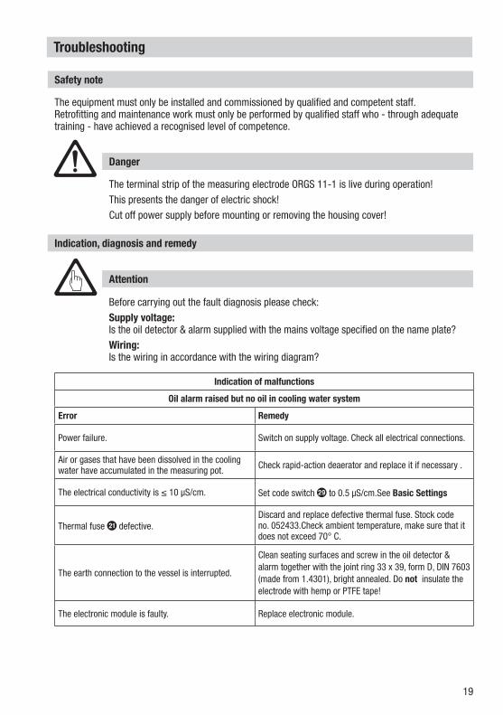
Before carrying out the fault diagnosis please check:Supply voltage: Is the oil detector & alarm supplied with the mains voltage specified on the name plate? Wiring: Is the wiring in accordance with the wiring diagram?
Indication, diagnosis and remedy
Indication of malfunctions
Oil alarm raised but no oil in cooling water system
Error Remedy
Power failure. Switch on supply voltage. Check all electrical connections.
Air or gases that have been dissolved in the cooling water have accumulated in the measuring pot. Check rapid-action deaerator and replace it if necessary .
The electrical conductivity is ≤ 10 μS/cm. Set code switch s to 0.5 μS/cm.See Basic Settings
Thermal fuse k defective.Discard and replace defective thermal fuse. Stock code no. 052433.Check ambient temperature, make sure that it does not exceed 70° C.
The earth connection to the vessel is interrupted.
Clean seating surfaces and screw in the oil detector & alarm together with the joint ring 33 x 39, form D, DIN 7603 (made from 1.4301), bright annealed. Do not insulate the electrode with hemp or PTFE tape!
The electronic module is faulty. Replace electronic module.
Safety note
Danger
The terminal strip of the measuring electrode ORGS 11-1 is live during operation! This presents the danger of electric shock!Cut off power supply before mounting or removing the housing cover!
The equipment must only be installed and commissioned by qualified and competent staff. Retrofitting and maintenance work must only be performed by qualified staff who - through adequate training - have achieved a recognised level of competence.

20
Troubleshooting
Exchanging the electronic module
1. Unscrew cover screws g and remove cover h. Fig. 6 2. Pull electrode wires from terminal lugs on circuit board. Remove the terminal strip n. 3. Unscrew the fixing screws t for the electronic module u and remove the module. The module is
available as spare part.. 4. Install the new electronic module in reverse order.
Spare parts list
Item DesignationStock code # Stock code #
ORGS 111 ORGS 112
u Electronic module NRV 1-43 321 321
k Thermal fuse Tmax 102 °C 052 433
Note
When ordering spare parts please state the material number indicated on the name plate.
continued

21
If faults occur that are not listed above or cannot be corrected, please contact our service centre or authorized agency in your country.
Removing and disposing of measuring electrode ORGS 111
Removing and disposing of measuring electrode ORGS 111
1. Close ball valves c and d.2. Switch off supply voltage.2. Undo cover screws g and remove the housing lid h.3. Detach the connecting wires from the terminals n and pull wires out of the cable gland. 4. Before removing the equipment make sure that is is neither hot nor under pressure.For the disposal of the measuring electrode observe the pertinent legal regulations concerning waste disposal.
Safety note
Danger
When loosening the measuring electrodes hot cooling water may escape.This presents the risk of severe scalding all over the body!Do not remove the measuring electrode ORGS 11-1 unless the boiler pressure is verified to be zero.The terminal strip of the measuring electrode ORGS 11-1 is live during operation! This presents the danger of electric shock!Cut off power supply before mounting or removing the housing cover!
The equipment must only be installed and commissioned by qualified and competent staff. Retrofitting and maintenance work must only be performed by qualified staff who - through adequate training - have achieved a recognised level of competence.

22
For your Notes

23
For your Notes

24810801-05/07-2017cm (808507-07) · GESTRA AG · Bremen · Printed in Germany
Agencies all over the world:
www.gestra.com
GESTRA AGMünchener Straße 77 28215 BremenGermanyTelefon +49 421 3503-0 Telefax +49 421 3503-393E-mail [email protected] www.gestra.de