getting started - digital river
TRANSCRIPT

1
Chapter
1
Getting StartedChapter 1:
In this chapter, you learn about navigating an HVAC project and designing HVAC systems with AutoCAD® MEP. The design process produces an HVAC system plan, which is submitted as a construction document to review agencies and contractors.
You use schematic diagrams to create the design layout and to draft many of the details associated with your design. After you place the schematic symbols and lines in a schematic diagram, an engineer will modify them when changes occur in the HVAC system plan. You add schematic symbols and lines in isometric mode to create a schematic diagram that represents ducts and fittings in 3D. Finally, you generate spaces to model the volumes, temperature and airflow within rooms and to add ceiling grids, to which you attach equipment such as diffusers.
Objectives
After completing this chapter, you will be able to:
■ Load base drawings for a project.■ Draw a schematic diagram.■ Generate spaces.■ Work with space engineering data.■ Add ceiling grids.

2 ■ Chapter 1: Getting Started
Lesson: Loading Base Drawings for a Project
Overview
This lesson introduces you to the key features of the AutoCAD MEP user interface and how to customize it to streamline the HVAC design process. You also learn to load base drawings such as:
■ Architectural drawings as a backdrop for your HVAC design.■ Reusable design elements such as a standard restroom HVAC layout.
Objectives
After completing this lesson, you will be able to:
■ List the types of workspaces available in AutoCAD MEP and describe their components.■ Explain the advantages of organizing building drawings into projects.■ State the characteristics of four specialized project drawing types.■ Describe how these four drawing types are used by project personnel.■ Describe how base drawings are organized spatially within a building.■ Describe best practices for loading base drawings into an MEP project.■ Start AutoCAD MEP, use and customize MEP-specific user interface elements, and load base
drawings for a project.
Lesson: Loading Base Drawings for a Project ■ 3
Workspaces
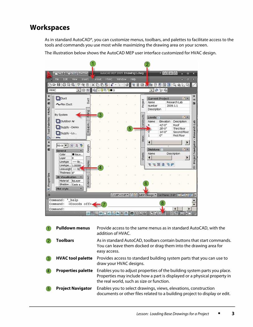
As in standard AutoCAD®, you can customize menus, toolbars, and palettes to facilitate access to the tools and commands you use most while maximizing the drawing area on your screen.
The illustration below shows the AutoCAD MEP user interface customized for HVAC design.
Pulldown menus Provide access to the same menus as in standard AutoCAD, with the addition of HVAC.
Toolbars As in standard AutoCAD, toolbars contain buttons that start commands. You can leave them docked or drag them into the drawing area for easy access.
HVAC tool palette Provides access to standard building system parts that you can use to draw your HVAC designs.
Properties palette Enables you to adjust properties of the building system parts you place. Properties may include how a part is displayed or a physical property in the real world, such as size or function.
Project Navigator Enables you to select drawings, views, elevations, construction documents or other files related to a building project to display or edit.

4 ■ Chapter 1: Getting Started
Definition of Workspace
A workspace is a task-based customization of the basic user interface. It includes the menus, toolbars, and palettes that you use most.
Examples of Workspaces
AutoCAD MEP software comes out of the box with four discipline-specific workspaces that you can select when you start the software: HVAC, Piping, Electrical, and Plumbing. You can modify your workspace as you go along by moving, hiding, or displaying additional toolbars and menus. If you find a configuration that you want to keep and reuse, you can name it and save it as a new workspace. For example, if you develop a unique workspace that helps you streamline the design of apartment complex HVAC systems, you might call it HVAC-Apartments.
AutoCAD MEP Projects
Typical building projects can require dozens of discipline-specific conceptual models, drawings, and construction documents to be generated. In AutoCAD MEP, these models, drawings and construction documents are stored in separate files, just as they are in standard AutoCAD, but in AutoCAD MEP, the files are organized into projects.
Definition of a Project
A project is a collection of files that include all the data related to a building design.
Advantages of MEP Projects
There are several advantages to organizing building design files into projects:
■ Powerful linking features ensure that files can be distributed over many different locations on your computer or on a network, enabling different people to work simultaneously on the same project.
■ Drawing and engineering standards for the project as a whole can be set and maintained automatically.
■ Standard AutoCAD XRef functionality has been enhanced to enable data from multiple drawings to be easily merged; for example, HVAC designs can be easily superimposed on architectural drawings.
Drawing window
status bar
As in standard AutoCAD, provides access to tools for scaling annotation, viewing cut planes, and a variety of specialized drawing settings and functions. These settings apply to the drawing within the window.
Command line As in standard AutoCAD, prompts for commands and command parameters.
Application
status bar
Provides access to navigational tools, coordinate values, snaps and layouts. There are additional snaps specific to AutoCAD MEP, that facilitate connecting building systems. These settings apply to the application as a whole, including all open drawings.
Lesson: Loading Base Drawings for a Project ■ 5
Project File Types
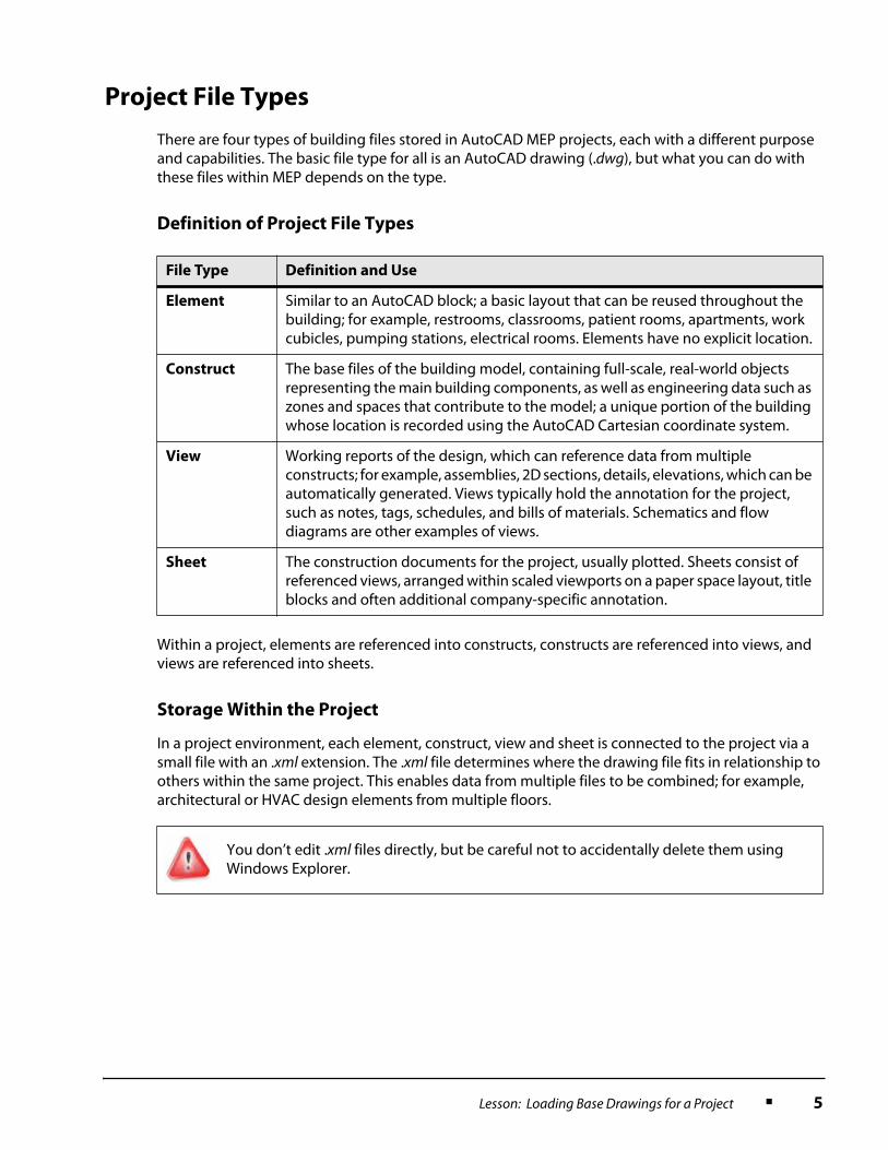
There are four types of building files stored in AutoCAD MEP projects, each with a different purpose and capabilities. The basic file type for all is an AutoCAD drawing (.dwg), but what you can do with these files within MEP depends on the type.
Definition of Project File Types
Within a project, elements are referenced into constructs, constructs are referenced into views, and views are referenced into sheets.
Storage Within the Project
In a project environment, each element, construct, view and sheet is connected to the project via a small file with an .xml extension. The .xml file determines where the drawing file fits in relationship to others within the same project. This enables data from multiple files to be combined; for example, architectural or HVAC design elements from multiple floors.
File Type Definition and Use
Element Similar to an AutoCAD block; a basic layout that can be reused throughout the building; for example, restrooms, classrooms, patient rooms, apartments, work cubicles, pumping stations, electrical rooms. Elements have no explicit location.
Construct The base files of the building model, containing full-scale, real-world objects representing the main building components, as well as engineering data such as zones and spaces that contribute to the model; a unique portion of the building whose location is recorded using the AutoCAD Cartesian coordinate system.
View Working reports of the design, which can reference data from multiple constructs; for example, assemblies, 2D sections, details, elevations, which can be automatically generated. Views typically hold the annotation for the project, such as notes, tags, schedules, and bills of materials. Schematics and flow diagrams are other examples of views.
Sheet The construction documents for the project, usually plotted. Sheets consist of referenced views, arranged within scaled viewports on a paper space layout, title blocks and often additional company-specific annotation.
You don’t edit .xml files directly, but be careful not to accidentally delete them using Windows Explorer.

6 ■ Chapter 1: Getting Started
Examples
The following illustrations show examples of project file types.
An element: the HVAC design for a standard restroom, which can be reused throughout a building
A construct: the architectural floor plan of a building, into which the HVAC restroom design element has been referenced

Lesson: Loading Base Drawings for a Project ■ 7
A view: a multi-floor section that passes through the restrooms
A sheet: containing two multi-floor sectional views, ready for plotting
8 ■ Chapter 1: Getting Started
Workflow in a Project
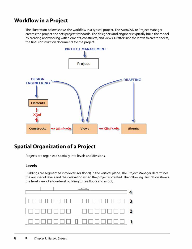
The illustration below shows the workflow in a typical project. The AutoCAD or Project Manager creates the project and sets project standards. The designers and engineers typically build the model by creating and working with elements, constructs, and views. Drafters use the views to create sheets, the final construction documents for the project.
Spatial Organization of a Project
Projects are organized spatially into levels and divisions.
Levels
Buildings are segmented into levels (or floors) in the vertical plane. The Project Manager determines the number of levels and their elevation when the project is created. The following illustration shows the front view of a four-level building (three floors and a roof).

Lesson: Loading Base Drawings for a Project ■ 9
Divisions
Divisions segment the building in the horizontal plane. Multiple divisions are used when a building layout would be too large and unwieldy to represent in a single construction document. A division might correspond to a wing (such as east and west), annexes, branches or building additions. The following illustration shows the top view of a building that has been assigned two divisions.
When you create a construct, such as a floor plan, you assign it to a level and a division.
10 ■ Chapter 1: Getting Started
Guidelines for Loading Base Drawings into Projects
There are many approaches to organizing base drawings within projects. The following guidelines can save time and reduce errors.
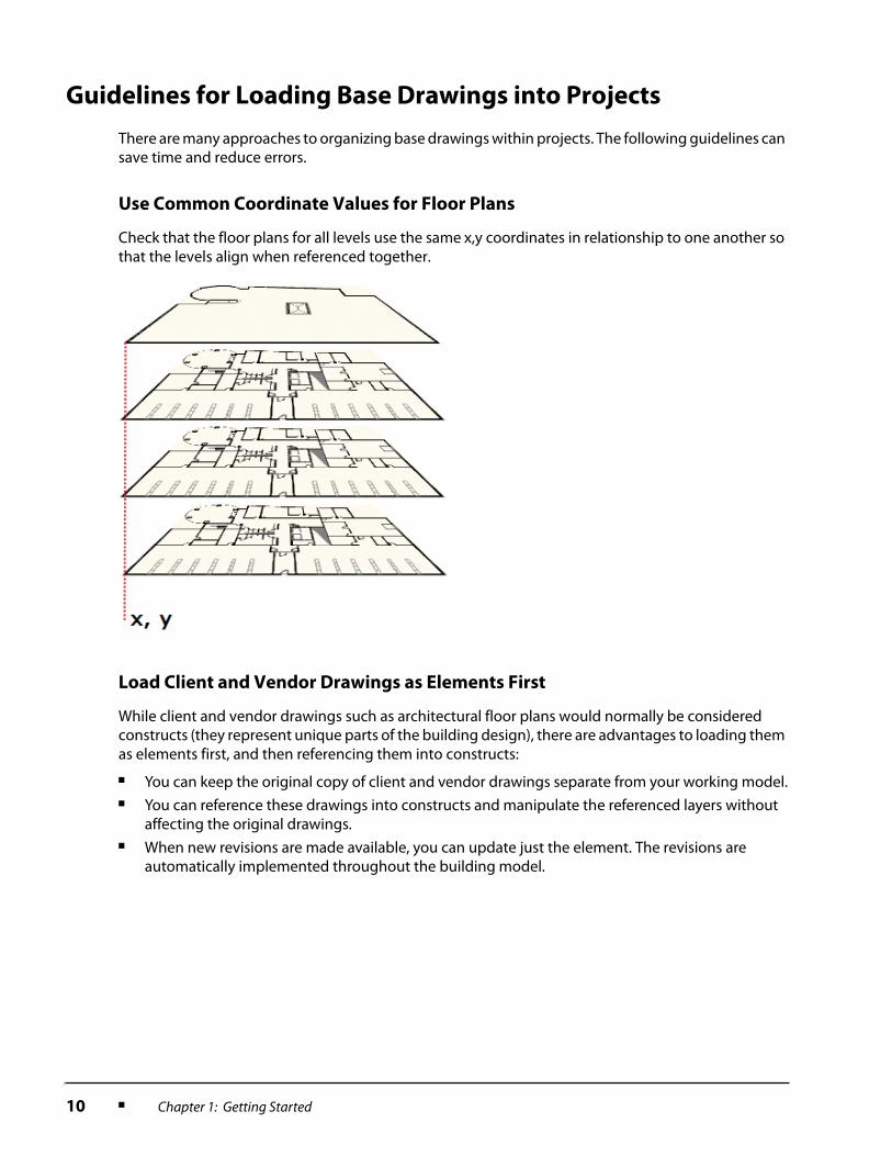
Use Common Coordinate Values for Floor Plans
Check that the floor plans for all levels use the same x,y coordinates in relationship to one another so that the levels align when referenced together.
Load Client and Vendor Drawings as Elements First
While client and vendor drawings such as architectural floor plans would normally be considered constructs (they represent unique parts of the building design), there are advantages to loading them as elements first, and then referencing them into constructs:
■ You can keep the original copy of client and vendor drawings separate from your working model.■ You can reference these drawings into constructs and manipulate the referenced layers without
affecting the original drawings.■ When new revisions are made available, you can update just the element. The revisions are
automatically implemented throughout the building model.
Lesson: Loading Base Drawings for a Project ■ 11
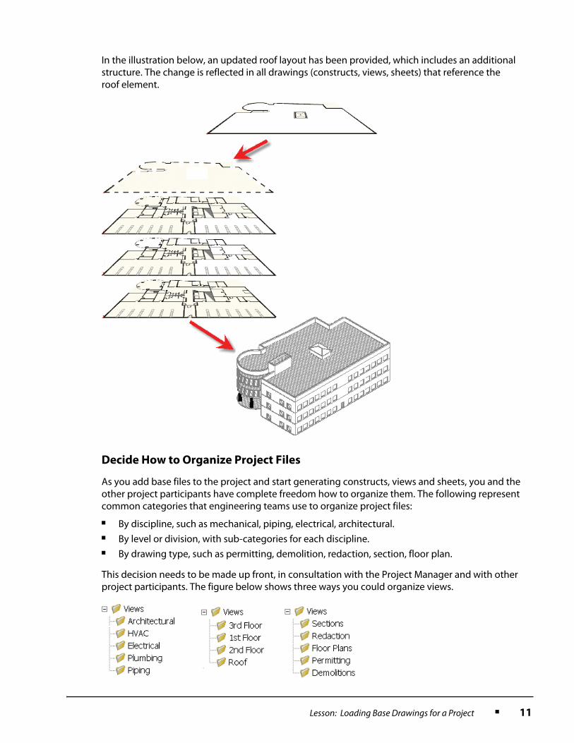
In the illustration below, an updated roof layout has been provided, which includes an additional structure. The change is reflected in all drawings (constructs, views, sheets) that reference the roof element.
Decide How to Organize Project Files
As you add base files to the project and start generating constructs, views and sheets, you and the other project participants have complete freedom how to organize them. The following represent common categories that engineering teams use to organize project files:
■ By discipline, such as mechanical, piping, electrical, architectural.■ By level or division, with sub-categories for each discipline.■ By drawing type, such as permitting, demolition, redaction, section, floor plan.
This decision needs to be made up front, in consultation with the Project Manager and with other project participants. The figure below shows three ways you could organize views.
12 ■ Chapter 1: Getting Started
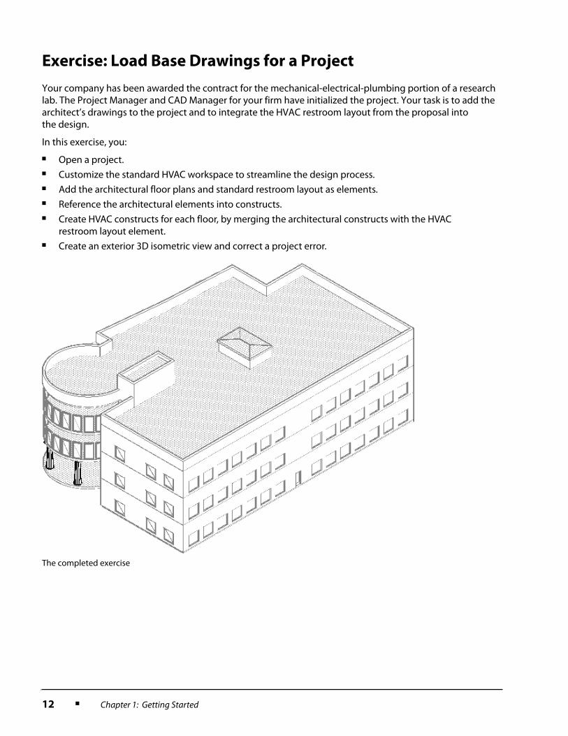
Exercise: Load Base Drawings for a Project
Your company has been awarded the contract for the mechanical-electrical-plumbing portion of a research lab. The Project Manager and CAD Manager for your firm have initialized the project. Your task is to add the architect’s drawings to the project and to integrate the HVAC restroom layout from the proposal into the design.
In this exercise, you:
■ Open a project.■ Customize the standard HVAC workspace to streamline the design process.■ Add the architectural floor plans and standard restroom layout as elements.■ Reference the architectural elements into constructs.■ Create HVAC constructs for each floor, by merging the architectural constructs with the HVAC
restroom layout element.■ Create an exterior 3D isometric view and correct a project error.
The completed exercise
Lesson: Loading Base Drawings for a Project ■ 13
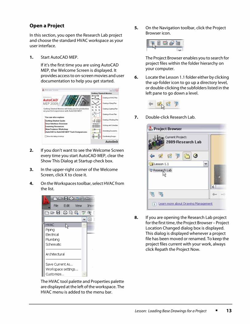
Open a Project
In this section, you open the Research Lab project and choose the standard HVAC workspace as your user interface.
1. Start AutoCAD MEP.
If it’s the first time you are using AutoCAD MEP, the Welcome Screen is displayed. It provides access to on-screen movies and user documentation to help you get started.
2. If you don’t want to see the Welcome Screen every time you start AutoCAD MEP, clear the Show This Dialog at Startup check box.
3. In the upper-right corner of the Welcome Screen, click X to close it.
4. On the Workspaces toolbar, select HVAC from the list.
The HVAC tool palette and Properties palette are displayed at the left of the workspace. The HVAC menu is added to the menu bar.
5. On the Navigation toolbar, click the Project Browser icon.
The Project Browser enables you to search for project files within the folder hierarchy on your computer.
6. Locate the Lesson 1.1 folder either by clicking the up-folder icon to go up a directory level, or double-clicking the subfolders listed in the left pane to go down a level.
7. Double-click Research Lab.
8. If you are opening the Research Lab project for the first time, the Project Browser – Project Location Changed dialog box is displayed. This dialog is displayed whenever a project file has been moved or renamed. To keep the project files current with your work, always click Repath the Project Now.

14 ■ Chapter 1: Getting Started
Customize the HVAC Workspace
In this section you customize the standard HVAC workspace. Both the HVAC tool palette and Properties palette are displayed undocked at the left side of the workspace by default. The Project Navigator is also undocked, blocking underlying drawings.
■ Dock the Project Navigator, Properties palette and HVAC tool palette.
■ Make the Modify toolbar accessible, which contains commonly used AutoCAD editing tools.
■ Save this customized workspace.
9. Click Close. The Project Navigator is added to your workspace. The Project tab is displayed, which shows the Research Lab project name, description, levels (4), and divisions (1).
1. Right-click the title bar of the HVAC tool palette. Click Allow Docking.
2. Right-click the title bar of the HVAC tool palette. Click Anchor Left. The auto-hide functionality is automatically activated when you dock the palette. Now, when you move the cursor over the title bar, all tabs on the palette become visible.
3. Repeat steps 1 and 2 for the Properties palette.
4. Repeat steps 1 and 2 for the Project Navigator, except click Anchor Right in step 2.

Lesson: Loading Base Drawings for a Project ■ 15
Add Base Drawings and Restroom Layout
as Elements
In this section, you add the architectural drawings that the client has provided and the restroom layout from the project proposal as elements.
5. Right-click any toolbar icon to display a list of available toolbars. Click Modify.
If this is the first time you have used the Modify toolbar using AutoCAD MEP, it is displayed vertically, docked at the right next to the Project Navigator toolbar.
6. Drag the Modify toolbar by its left edge and dock it in the toolbars area along the upper edge of the display area.
7. To save your new workspace arrangement, select Save Current As from the list on the Workspace toolbar.
8. In the Save Workspace dialog box, enter a descriptive name such as My HVAC. Click Save.
9. To test your new workspace, switch to the Schematic workspace and then back to the workspace you saved in step 8.
1. In the Project Navigator, click the Constructs tab.
To facilitate referencing elements into constructs, both elements and constructs are stored on the Constructs tab.

16 ■ Chapter 1: Getting Started
2. Right-click Elements. Click New > Category.
3. To name the category, enter Client Drawings and press ENTER.
4. Repeat steps 2 and 3 to create a subcategory of Client Drawings called Architectural.
5. Repeat steps 2 and 3 to create a subcategory of Elements called Restroom Layout.
6. Using the standard AutoCAD Open command, open the drawing 1st Floor.dwg.
7. In the Project Navigator, Constructs tab, right-click the Architectural subcategory that you created in step 4. Click Save Current Dwg As Element.
8. In the Add Element dialog box, make sure the Open in Drawing Editor check box is clear. Click OK.
Notice that the new element is shown with a padlock icon. No other project participant can edit the drawing while you have it open.
9. Close the drawing using the standard AutoCAD Close command.
10. When asked whether you want to save the drawing, click No, since you have made no changes.
11. Repeat steps 6 through 10 to load the following architectural drawings as elements:
■ 2nd Floor.dwg■ 3rd Floor.dwg■ Roof.dwg
12. Repeat steps 6 through 10 to load the drawing Restrooms – HVAC.dwg as an element in the Restroom Layout category.
13. Right-click the element Restrooms – HVAC that you just added. Rename it HVAC.
Your elements should now be organized as follows:

Lesson: Loading Base Drawings for a Project ■ 17
Reference Architectural Elements into
Constructs
In this section, you reference the architectural drawings that you loaded as elements into the constructs that you will use as the basis for your model.
1. In the Project Navigator, Constructs tab:
■ Right-click Constructs. Click New > Category.
■ Name the category Architectural.
2. Right-click the Architectural construct category. Click New > Construct.
3. Set the following parameters:
■ Name: 01 Arch.■ Description: Architectural Layout
First Floor.■ Under Assignments, select the check box
for Level 1 First Floor and Division Main.■ Select the Open in Drawing Editor
check box.
■ Click OK.
A new construct named 01 Arch is opened in your AutoCAD MEP session.
4. Drag and drop the Element > Architectural > 1st Floor anywhere into the open construct.
5. Zoom to extents.
The doors, walls, and windows, which were created using AutoCAD for Architecture, are displayed as grey-screened objects as a backdrop for your MEP design. Standard AutoCAD objects are not grey-screened. You control their display using the standard AutoCAD Layer Manager.
6. Open the Layer Manager.
7. Change the Color and Lineweight to 8 and 0.18 mm for the following layers:
Imperial:
■ 1st Floor|A-Flor-Evtr■ 1st Floor|A-Flor-Spcl■ 1st Floor|A-Wall-Chas■ 1st Floor|I-Furn
Metric:
■ 1st Floor|A-SanitaryFitting-G■ 1st Floor|A661G■ 1st Floor|A780G■ 1st Floor||Aec_Chase
8. Click Apply. The remaining objects in the floor plan are grey-screened.
9. From the Layer Manager, open the Layer States Manager.
18 ■ Chapter 1: Getting Started
Create HVAC Constructs and Start Your
Design
In this section, you create HVAC constructs to start your design. The HVAC constructs will reference both other constructs (architectural) and elements (the standard restroom layout).
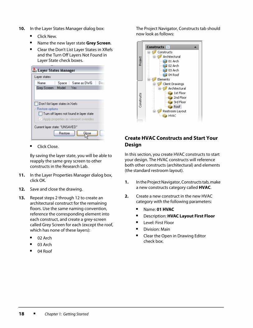
10. In the Layer States Manager dialog box:
■ Click New.■ Name the new layer state Grey Screen.■ Clear the Don’t List Layer States in XRefs
and the Turn Off Layers Not Found in Layer State check boxes.
■ Click Close.
By saving the layer state, you will be able to reapply the same grey screen to other constructs in the Research Lab.
11. In the Layer Properties Manager dialog box, click OK.
12. Save and close the drawing.
13. Repeat steps 2 through 12 to create an architectural construct for the remaining floors. Use the same naming convention, reference the corresponding element into each construct, and create a grey-screen called Grey Screen for each (except the roof, which has none of these layers):
■ 02 Arch■ 03 Arch■ 04 Roof
The Project Navigator, Constructs tab should now look as follows:
1. In the Project Navigator, Constructs tab, make a new constructs category called HVAC.
2. Create a new construct in the new HVAC category with the following parameters:
■ Name: 01 HVAC
■ Description: HVAC Layout First Floor
■ Level: First Floor■ Division: Main■ Clear the Open in Drawing Editor
check box.

Lesson: Loading Base Drawings for a Project ■ 19
A new construct named 01 HVAC is created in the Project Navigator, but it is not opened in the drawing window.
3. Repeat steps 1 and 2 to create an HVAC construct for the second and third floors.
4. To open the 01 HVAC construct, double-click its name.
5. Drag and drop the 01 Arch construct into the open 01 HVAC construct drawing. Zoom to extents.
6. In the Layer States Manager:
■ Click 01 Arch_Grey Screen.■ Click Restore.
7. Drag and drop the Restroom Layout > HVAC element into the open drawing. Since the 0,0 coordinates of the restroom element align with the 0,0 coordinates of the architectural floor plan, the restroom layout is automatically placed in the correct location.
8. Save and close the construct.
9. Repeat steps 4 through 6 to open, reference the architectural floor plan, and apply the grey screen for the second and third floors.

20 ■ Chapter 1: Getting Started
Create an Exterior 3D Isometric View and
Correct a Project Error
In this section, you create your first MEP view of the full exterior of the building, combining data from the four floor constructs. You discover an error in the project setup and correct it for all project drawings.
10. To reference the HVAC restroom layout element to the second and third floors simultaneously, right-click Restroom Layout > HVAC. Click Attach Element to Constructs.
11. In the Attach Element to Construct dialog box:
■ Expand the HVAC folder.■ Select the check boxes for 02 HVAC and
03 HVAC. (01 HVAC is already selected.)
■ Click OK.
12. Save and close both constructs.
1. In the Project Navigator, Views tab, right-click Views > New Category. Name the new category Architectural.
2. Right-click the new Architectural category. Click New View Dwg > General.
3. In the Add General View dialog box, General section:
■ For Name, enter Exterior Iso.
■ Click Next.

Lesson: Loading Base Drawings for a Project ■ 21
4. In the Context section:
■ Select the check boxes for all four levels in the division Main.
■ Click Next.
5. In the Content section, since this is an exterior view, you need only the Architectural drawings:
■ Clear the check boxes for HVAC constructs.
■ Click Finish.
6. In the Project Navigator, Views tab, double-click Exterior Iso to open it.
7. On the Navigation toolbar, Views flyout, click the icon for SW Isometric.
8. On the Navigation toolbar, Visual Styles flyout, click the icon for 3D Hidden.
When the view regenerates, notice that the roof appears to have fallen into the third floor. This means either the roof has been drawn incorrectly or the elevation is incorrect in the project definition.

22 ■ Chapter 1: Getting Started
Challenge Exercise
The client gives you updated architectural drawings. You will replace the existing plans with the new drawings. All referenced constructs and views will be updated automatically:
■ Open the file Revised 1st Floor.dwg using the standard AutoCAD Open command.
■ Use the standard AutoCAD Save As command to overwrite the original element file located in the Lesson 1.1\ Research Lab\Elements\Client Drawings\Architectural folder.
■ Repeat these steps to update the plans for the second and third floors and the roof.
■ Open the view Exterior Iso. The revisions have been applied.
9. In the Project Navigator, Project tab, notice that the elevation of the roof is only 4'-0" [1200 mm] above the elevation of the third floor. To fix this, click the Edit Levels icon to the right of the Levels area title.
10. In the Levels dialog box:
■ Verify that the Auto-Adjust Elevation check box is selected.
■ Change the Floor to Floor Height of Level 3 to 14'-0" [4200 mm].
■ Click OK.
11. When asked to regenerate all views, click Yes.
All drawings in the project are updated according to the change in elevation, including the open view.
12. Save and close Exterior Iso.
Lesson: Drawing a Schematic Diagram ■ 23
Lesson: Drawing a Schematic Diagram
Overview
This lesson teaches you to draw a schematic diagram.
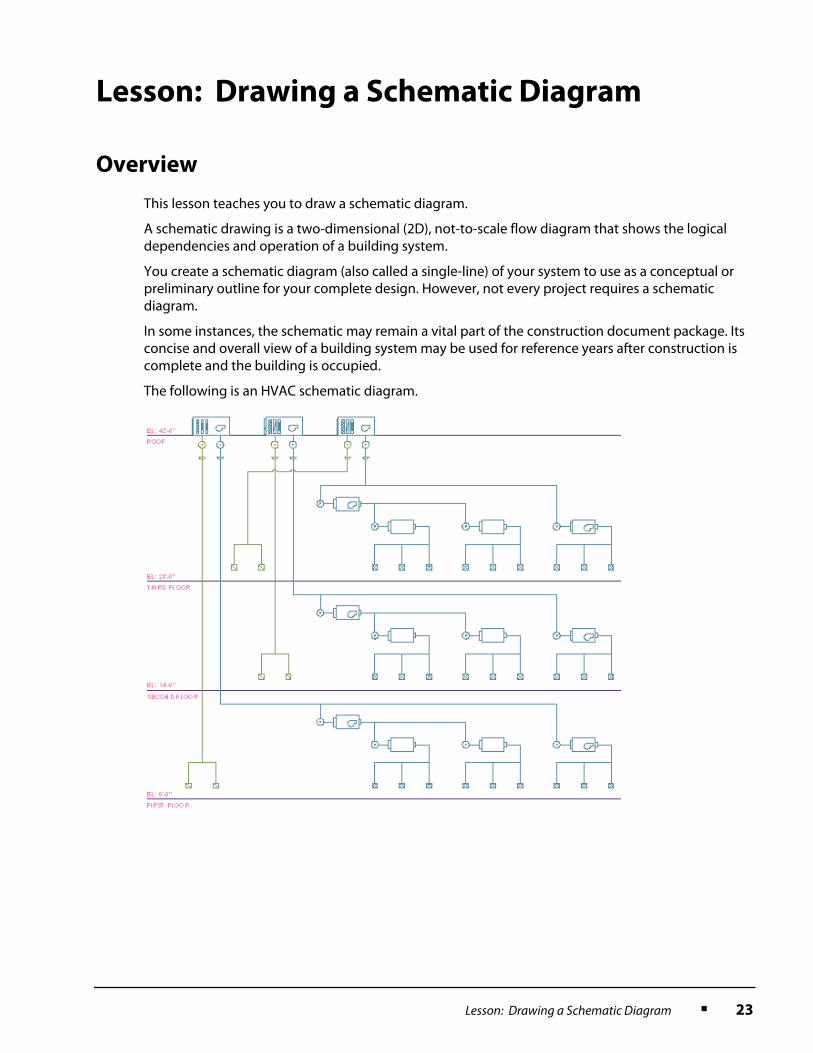
A schematic drawing is a two-dimensional (2D), not-to-scale flow diagram that shows the logical dependencies and operation of a building system.
You create a schematic diagram (also called a single-line) of your system to use as a conceptual or preliminary outline for your complete design. However, not every project requires a schematic diagram.
In some instances, the schematic may remain a vital part of the construction document package. Its concise and overall view of a building system may be used for reference years after construction is complete and the building is occupied.
The following is an HVAC schematic diagram.

24 ■ Chapter 1: Getting Started
Objectives
After completing this lesson, you will be able to:
■ Describe how schematic diagrams are implemented in AutoCAD MEP.■ Describe a schematic symbol and what it represents in an HVAC system.■ Describe a schematic line and what it represents in an HVAC system.■ Define a style.■ List advantages of schematic line and symbol connectivity.■ State one advantage of organizing schematic lines and symbols into systems.■ State one advantage of organizing schematic systems into groups.■ Describe practices to streamline the creation of schematic diagrams.■ Create a schematic diagram from start to finish.
Schematic Diagrams in AutoCAD MEP
HVAC schematic diagrams in AutoCAD MEP consist of schematic lines representing duct connected to schematic symbols representing equipment, fittings and controls. You draw schematic lines just as you draw regular lines in AutoCAD. You add schematic symbols just as you add objects in AutoCAD, using an insertion point for placement and a rotation angle.
Power of Schematic Lines and Symbols
However, AutoCAD MEP schematic lines and symbols are more powerful than AutoCAD lines and objects because they snap together using connection points built into each schematic symbol, enabling you to create an intelligent building system diagram that captures the logical dependencies and functional relationships among system parts.
Schematic Diagrams Stored as Views
Since schematic diagrams represent the flow of an entire building system or project and are not to scale, they do not usually reference information in constructs. They are classified as and stored as views.
Since schematics are not to scale, they are usually drawn at a scale of 1:1 (one inch [1 mm] in the diagram represents one inch [1 mm] in plotted output).

Lesson: Drawing a Schematic Diagram ■ 25
Schematic Symbols
Equipment, fittings and controls are depicted with schematic symbols such as those shown below. AutoCAD MEP comes out of the box with hundreds of commonly recognized industry-standard symbols. You can also create your own to reflect specialized equipment or design needs.
Definition of Schematic Symbols
Schematic symbols represent real-world parts such as equipment, fittings and controls. They consist of AutoCAD blocks, but they are more powerful than blocks. They snap together to represent the connectivity and functional dependencies of real-world parts and equipment. They are not to scale and seldom look like the real-world part they represent.
Examples of Schematic Symbols
The illustration below shows a schematic symbol representing a ventilator:
■ It has two location grips (the squares) that enable you to move the symbol in the XY plane.■ The two plus signs are connectors at which the ventilator can be connected to schematic lines
representing duct. Schematic symbols can have one or more connectors, depending on the functional characteristics of the equipment, fitting or control that the symbol represents.
■ The two flip arrows at the bottom enable you to change the orientation of the symbol to match the HVAC system’s direction of flow.
The schematic symbol below represents a diffuser. It has one location grip, one connector, and no flip arrows.
Fan
Concentric Transition
Thermostat
26 ■ Chapter 1: Getting Started
Schematic Lines
The ductwork in your diagram is depicted using schematic lines.
Definition of Schematic Lines
Schematic lines represent ductwork within the building system. While schematic lines appear similar to AutoCAD polylines, they connect intelligently to other schematic lines and symbols, transmitting information about function, size and shape.
Examples of Schematic Lines
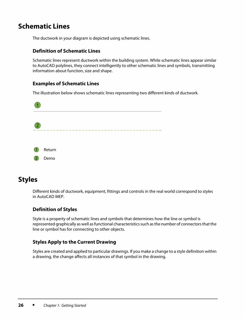
The illustration below shows schematic lines representing two different kinds of ductwork.
Styles
Different kinds of ductwork, equipment, fittings and controls in the real world correspond to styles in AutoCAD MEP.
Definition of Styles
Style is a property of schematic lines and symbols that determines how the line or symbol is represented graphically as well as functional characteristics such as the number of connectors that the line or symbol has for connecting to other objects.
Styles Apply to the Current Drawing
Styles are created and applied to particular drawings. If you make a change to a style definition within a drawing, the change affects all instances of that symbol in the drawing.
Return
Demo

Lesson: Drawing a Schematic Diagram ■ 27
Connecting Schematic Lines and Symbols
The ability to connect schematic lines and symbols intelligently can facilitate the production of schematic diagrams in several ways:
■ If you have to edit the diagram, connected components move together.■ When one component is connected to another, it inherits information about size and function
from the first part. You don’t have to re-enter the same properties for every component.■ The sharing of information between connected parts helps maintain consistency.■ Connection rules can be set for different styles of ductwork, equipment, fittings and controls, so
that only logical or functional connections are permitted. This can save time and prevent errors.
Definition of Schematic Connectors
AutoCAD MEP uses two additional snaps to enable you to connect schematic lines and symbols intelligently, as shown in the table below.
Examples of Schematic Connectors
In the illustration below, line 1 is unconnected. Line 2 is the same line as it appears when you connect a schematic symbol (a diffuser) at the end.
In the illustration below, line 1 is unconnected. Line 2 is the same line as it appears when you connect a schematic symbol (a diffuser) within the line. MEP presents schematic curve connectors along the length of the line.
Snap Definition
Schematic End Connector Enables a schematic line or symbol to be connected to the end of another line or symbol. Also called a “Schematic Connector”.
Schematic Curve
Connector
Enables a schematic line or symbol to be connected within a line.
28 ■ Chapter 1: Getting Started
Behavior of Connected Lines and Symbols
The style definition for schematic symbols determines how the symbol behaves when it is connected to a line. Many in-line symbols such as sensors:
■ Move with the schematic line when the schematic line moves, or can be used as “handles” to move or stretch the line.
■ Are erased when you erase the schematic line.■ Can be repositioned along the schematic line.
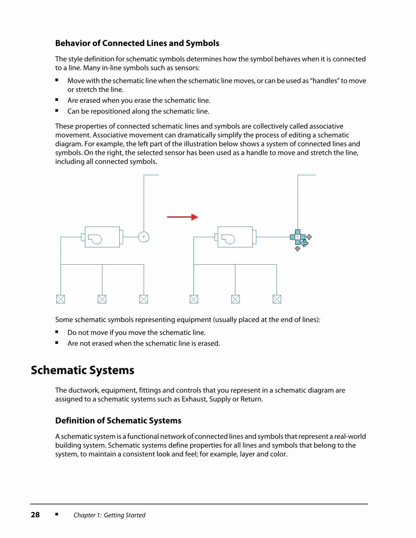
These properties of connected schematic lines and symbols are collectively called associative movement. Associative movement can dramatically simplify the process of editing a schematic diagram. For example, the left part of the illustration below shows a system of connected lines and symbols. On the right, the selected sensor has been used as a handle to move and stretch the line, including all connected symbols.
Some schematic symbols representing equipment (usually placed at the end of lines):
■ Do not move if you move the schematic line.■ Are not erased when the schematic line is erased.
Schematic Systems
The ductwork, equipment, fittings and controls that you represent in a schematic diagram are assigned to a schematic systems such as Exhaust, Supply or Return.
Definition of Schematic Systems
A schematic system is a functional network of connected lines and symbols that represent a real-world building system. Schematic systems define properties for all lines and symbols that belong to the system, to maintain a consistent look and feel; for example, layer and color.
Lesson: Drawing a Schematic Diagram ■ 29
Example of Schematic Systems
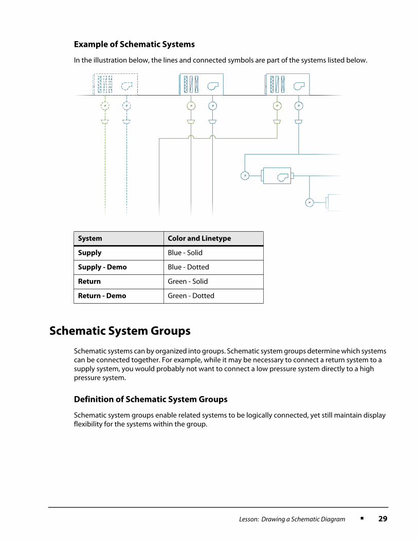
In the illustration below, the lines and connected symbols are part of the systems listed below.
Schematic System Groups
Schematic systems can by organized into groups. Schematic system groups determine which systems can be connected together. For example, while it may be necessary to connect a return system to a supply system, you would probably not want to connect a low pressure system directly to a high pressure system.
Definition of Schematic System Groups
Schematic system groups enable related systems to be logically connected, yet still maintain display flexibility for the systems within the group.
System Color and Linetype
Supply Blue - Solid
Supply - Demo Blue - Dotted
Return Green - Solid
Return - Demo Green - Dotted

30 ■ Chapter 1: Getting Started
Example of Schematic System Groups
In the following illustration, Supply (blue) and Return (green) lines and symbols are both connected to Supply (blue) equipment. This is a valid connection because both lines belong to a group called DUCT.
Guidelines for Creating a Schematic Diagram
The following guidelines can help you streamline the creation of schematic diagrams.
Set Up Groups and Systems Before You Start
It saves time to plan the logical connectivity (groups) and display characteristics (systems) of your schematic diagram before you start. In many cases, this may be done by your Project or CAD Manager, to maintain consistency throughout the project.
Use the Schematic Workspace
The Schematic workspace gives you easy access to the Schematic menu, commands and Schematic tool palette.

Lesson: Drawing a Schematic Diagram ■ 31
Use Appropriate Drafting Settings
To facilitate quick and accurate placement of schematic lines and symbols, turn on:
■ Snap mode.■ Ortho mode.■ Object Snap.■ Object snap tracking.■ Dynamic input.■ Snapping to schematic connectors (MEP snaps).
Turn Off Solution Tips
Solution tips are on-screen graphic alerts that show you the location of invalid connections between schematic lines and symbols.
Solution tips are useful to help you check connections when you are done a schematic diagram, but can be distracting while you are creating it.
Use Annotation Scale
Use annotation scale to set the scale of the schematic view in relationship to the scale of the construction document. The annotation scale maintains consistent symbol sizes throughout all schematic sheets.
Place Schematic Lines and Symbols in a Logical Order
To take advantage of the full power of schematic system connectivity, draw the components of a schematic diagram in the following order:
1. Place end-of-line symbols first. End-of-line symbols generally represent equipment but may also represent a control or fitting that connects to existing lines.
2. Add the schematic lines that represent the ductwork next, by connecting the beginning of the schematic line to an end-of-line symbol.
32 ■ Chapter 1: Getting Started
3. Add in-line symbols last. In-line symbols usually represent in-line equipment such as diffusers, sensors or controls, and may be connected anywhere along a schematic line.
Reset the Scales of a Schematic Symbol in Its Style
If the default scale for a symbol style supplied with AutoCAD MEP is inappropriate, reset the scale for the style as a whole instead of resizing one symbol at a time using the AutoCAD Scale command.
Use the Compass
The AutoCAD MEP compass tool is a more powerful and efficient tool than polar tracking for drawing objects at a precise angular rotation. For example, you could use the compass to draw a duct at 90 degrees to a wall.
The compass tool enables you to set an incremental angular snap (the default is 15 degrees) and tick marks around the perimeter of the compass to enable you to visualize the angles of insertion.
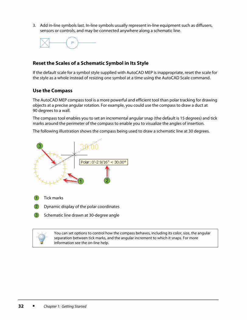
The following illustration shows the compass being used to draw a schematic line at 30 degrees.
Tick marks
Dynamic display of the polar coordinates
Schematic line drawn at 30-degree angle
You can set options to control how the compass behaves, including its color, size, the angular separation between tick marks, and the angular increment to which it snaps. For more information see the on-line help.

Lesson: Drawing a Schematic Diagram ■ 33
Exercise: Create a Schematic Diagram
In this exercise, you create a schematic diagram by adding and connecting schematic lines and symbols. You also edit the schematic lines and symbols graphically and edit the properties of the schematic lines and symbols.
It’s your task to create the initial design of the Ventilation System for the Research Lab. You will create an HVAC schematic showing the main design components.
The Project or CAD Manager for your firm has created a layout for the drawing as follows:
■ It has a border on a non-plot layer sized to fit the 24" x 36" [594 mm x 841 mm] title block for this project.■ As with most schematics, the drawing has a 1:1 annotation scale (each inch [mm] in the schematic
corresponds to one inch [mm] on paper).■ It includes a skeleton of lines and annotation for each floor in the Research Lab, to help you situate the lines
and symbols that will make up your design.■ The drawing also includes some predefined Symbols as covered in the AOTC Manager’s Essentials course.■ The schematic systems follow American Institute of Architecture (AIA) standards for layer organization and
properties.
In this exercise, you:
■ Start a schematic diagram.■ Add Schematic Symbols.■ Add a Schematic Line.■ Add In-Line Symbols and a Return Line.■ Add a VAV System.■ Complete the Supply System for each Floor.■ Complete the Return System.■ Finish the Ventilation System.
34 ■ Chapter 1: Getting Started
Start a Schematic Diagram
In this section, you switch to the Schematic workspace and start a schematic diagram using the Views tab on the Project Navigator.
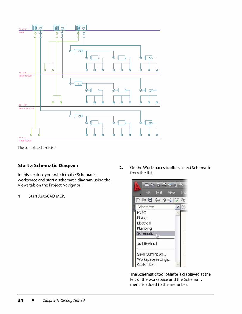
The completed exercise
1. Start AutoCAD MEP.
2. On the Workspaces toolbar, select Schematic from the list.
The Schematic tool palette is displayed at the left of the workspace and the Schematic menu is added to the menu bar.

Lesson: Drawing a Schematic Diagram ■ 35
Add Schematic Symbols
In this section, you add schematic symbols representing. You learn to scale symbols.
3. Using the Project Browser, locate and open the Lesson 1.2 folder.
4. Open the Research Lab project.
5. In the Project Navigator, Views Tab, create a new Category named Schematics.
6. Using the standard AutoCAD Open command, open the drawing entitled HVAC System Schematic.dwg.
7. In the Project Navigator, Views tab, right-click the new Schematics category. Click Save Current Dwg As View > General.
8. In the Add General View dialog box, General section:
■ For Name, enter Ventilation System.■ For Description, enter Duct Schematic
for Ventilation System.■ Click Next.
9. In the Context section, leave all level and division check boxes empty. You will not be including constructs in the ventilation schematic. Click Next.
10. In the Content section, leave all construct check boxes empty. Click Finish.
1. On the Schematic tool palettes, click the Duct tab.
The Duct tab provides access to a generic schematic line, a couple of predefined duct systems and equipment. Sensor and control symbols are also available since they are usually placed with schematic lines.
2. Under Equipment, click any tool.
3. On the Property palette, under General, click the graphic representation of the symbol for the style you picked.

36 ■ Chapter 1: Getting Started
4. In the Select a Style dialog box:
■ Select <Current Drawing> from the Drawing File list.
■ Select AHU Rooftop.
■ Click OK.
5. On the Properties palette, set the following:
■ Select H-Supply (SUP) from the System list.
■ Select Bottom Center from the Justification list.
■ Under Advanced, for ID, enter AHU-1.
6. To specify the insertion point, enter 5.5,21 [150,525].
7. Press ENTER to accept the default of 0 for the rotation.
8. On the Duct tool palette, under Equipment, click Fans – Duct.
9. On the Properties palette:
■ Verify H-Supply (SUP) is selected from the System list.
■ Under Advanced, clear the ID value.
10. To specify the insertion point, enter 6.25,21.5 [160,535].
11. Press ENTER to accept the default of 0 for the rotation.
This fan is too small for our drawing and needs to be scaled up.
12. Select and right-click the fan. Click Edit Schematic Symbol Style.
13. In the Schematic Symbol Styles dialog box, click the Views tab.
14. Under Scaling:
■ Verify the Use Annotation Scale and Override Scale options are selected.
■ Under Override Scale, enter 16 [8] for the x, y, and z axes. This will scale the symbol 4 [2] times larger in each direction.
■ Click OK.
The fan symbol is now be larger in comparison to the AHU symbol.

Lesson: Drawing a Schematic Diagram ■ 37
Add a Schematic Line
In this section, you use snaps, dynamic input, and the AutoCAD MEP compass to place the first schematic line in the ventilation schematic drawing. The line represents the main air supply line to the first floor of the building.
15. Use the Copy command to copy both symbols twice along the roof line. Placing a second unit 4" [100 mm] to the right and a third 8" [200 mm] to the right.
16. Use the Properties palette to change the ID of the middle AHU Rooftop unit to AHU-2 and the righthand unit to AHU-3.
1. Make sure that the following AutoCAD drafting settings are active:
■ Snap mode set to 1/4" [5 mm].■ Ortho mode.■ Object snap with Endpoint set.■ Object snap tracking.■ Dynamic input.
2. To make sure that you will be able to snap to schematic connectors:
■ Right-click Object snap. Click Settings.
■ In the Drafting Settings dialog box, Object Snap tab, scroll down to the AutoCAD MEP section. All MEP snaps should be active.
■ Click OK.
3. To turn solution tips off:
■ Click View menu. By default, solution tips are active, indicated by a check mark to the left of Show Solution Tips.
■ Click Show Solution Tips to remove the check mark and deactivate the command.
4. On the Duct tool palette, under Line by System, click Supply-Demo.
5. On the Properties palette, verify the following settings:
■ Standard is selected from the Style list.■ H-Supply-Demo is selected from the
System list.
38 ■ Chapter 1: Getting Started
Add In-Line Symbols and a Return Line
In this section, you add a pressure sensor and transition to the supply line. You also add a return line and copy the sensor and transition to this line.
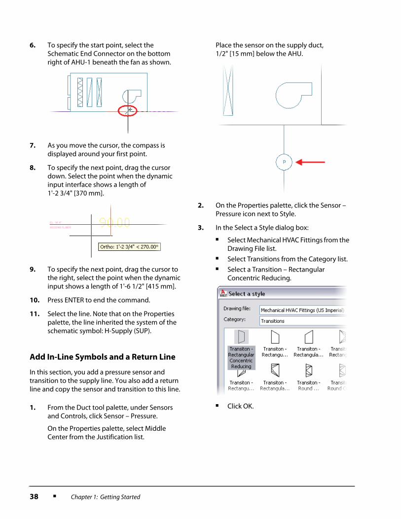
6. To specify the start point, select the Schematic End Connector on the bottom right of AHU-1 beneath the fan as shown.
7. As you move the cursor, the compass is displayed around your first point.
8. To specify the next point, drag the cursor down. Select the point when the dynamic input interface shows a length of 1'-2 3/4" [370 mm].
9. To specify the next point, drag the cursor to the right, select the point when the dynamic input shows a length of 1'-6 1/2" [415 mm].
10. Press ENTER to end the command.
11. Select the line. Note that on the Properties palette, the line inherited the system of the schematic symbol: H-Supply (SUP).
1. From the Duct tool palette, under Sensors and Controls, click Sensor – Pressure.
On the Properties palette, select Middle Center from the Justification list.
Place the sensor on the supply duct, 1/2" [15 mm] below the AHU.
2. On the Properties palette, click the Sensor – Pressure icon next to Style.
3. In the Select a Style dialog box:
■ Select Mechanical HVAC Fittings from the Drawing File list.
■ Select Transitions from the Category list.■ Select a Transition – Rectangular
Concentric Reducing.
■ Click OK.
Lesson: Drawing a Schematic Diagram ■ 39
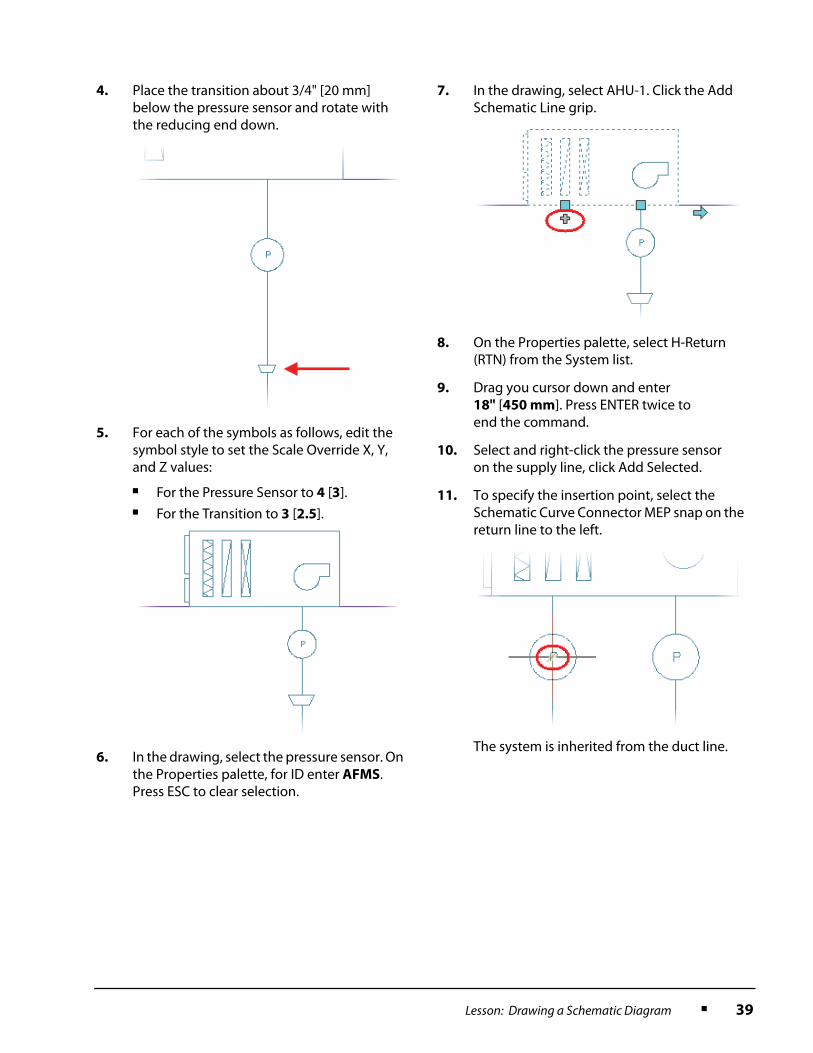
4. Place the transition about 3/4" [20 mm] below the pressure sensor and rotate with the reducing end down.
5. For each of the symbols as follows, edit the symbol style to set the Scale Override X, Y, and Z values:
■ For the Pressure Sensor to 4 [3].■ For the Transition to 3 [2.5].
6. In the drawing, select the pressure sensor. On the Properties palette, for ID enter AFMS. Press ESC to clear selection.
7. In the drawing, select AHU-1. Click the Add Schematic Line grip.
8. On the Properties palette, select H-Return (RTN) from the System list.
9. Drag you cursor down and enter 18" [450 mm]. Press ENTER twice to end the command.
10. Select and right-click the pressure sensor on the supply line, click Add Selected.
11. To specify the insertion point, select the Schematic Curve Connector MEP snap on the return line to the left.
The system is inherited from the duct line.
40 ■ Chapter 1: Getting Started
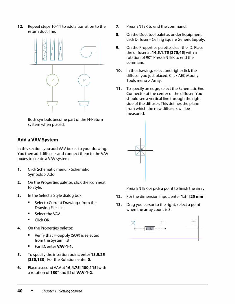
Add a VAV System
In this section, you add VAV boxes to your drawing. You then add diffusers and connect them to the VAV boxes to create a VAV system.
12. Repeat steps 10-11 to add a transition to the return duct line.
Both symbols become part of the H-Return system when placed.
1. Click Schematic menu > Schematic Symbols > Add.
2. On the Properties palette, click the icon next to Style.
3. In the Select a Style dialog box:
■ Select <Current Drawing> from the Drawing File list.
■ Select the VAV.■ Click OK.
4. On the Properties palette:
■ Verify that H-Supply (SUP) is selected from the System list.
■ For ID, enter VAV-1-1.
5. To specify the insertion point, enter 13,5.25 [330,130]. For the Rotation, enter 0.
6. Place a second VAV at 16,4.75 [400,115] with a rotation of 180° and ID of VAV-1-2.
7. Press ENTER to end the command.
8. On the Duct tool palette, under Equipment click Diffuser – Ceiling Square Generic Supply.
9. On the Properties palette, clear the ID. Place the diffuser at 14.5,1.75 [375,45] with a rotation of 90°. Press ENTER to end the command.
10. In the drawing, select and right-click the diffuser you just placed. Click AEC Modify Tools menu > Array.
11. To specify an edge, select the Schematic End Connector at the center of the diffuser. You should see a vertical line through the right side of the diffuser. This defines the plane from which the new diffusers will be measured.
Press ENTER or pick a point to finish the array.
12. For the dimension input, enter 1.5" [25 mm].
13. Drag you cursor to the right, select a point when the array count is 3.
Lesson: Drawing a Schematic Diagram ■ 41
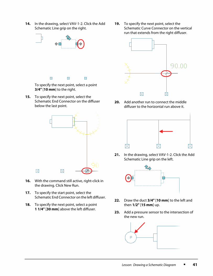
14. In the drawing, select VAV-1-2. Click the Add Schematic Line grip on the right.
To specify the next point, select a point 3/4" [10 mm] to the right.
15. To specify the next point, select the Schematic End Connector on the diffuser below the last point.
16. With the command still active, right-click in the drawing. Click New Run.
17. To specify the start point, select the Schematic End Connector on the left diffuser.
18. To specify the next point, select a point 1 1/4" [30 mm] above the left diffuser.
19. To specify the next point, select the Schematic Curve Connector on the vertical run that extends from the right diffuser.
20. Add another run to connect the middle diffuser to the horizontal run above it.
21. In the drawing, select VAV-1-2. Click the Add Schematic Line grip on the left.
22. Draw the duct 3/4" [10 mm] to the left and then 1/2" [15 mm] up.
23. Add a pressure sensor to the intersection of the new run.

42 ■ Chapter 1: Getting Started
Complete the Supply System
for each Floor
In this section, you copy objects to complete the VAV systems for each floor. You also add schematic lines to connect the VAV systems to the corresponding AHUs.
24. To move the sensor down, along with the duct and VAV-1-2 connected to it:
■ Select the sensor added in the last step.■ Click any of the four location grips.■ Drag your cursor straight down.■ Press TAB to activate the vertical dynamic
dimension.■ Enter 0.75" [15 mm].
Because of associative movement the entire horizontal plane for the sensor and VAV box shifts as one.
To rotate VAV-1-2 to the correct direction of flow:
■ Select VAV-1-2.■ Click both flip grips once.
The smaller connection ends up on the right and the grips on the bottom.
1. Copy the VAV-1-2 system (9 objects) to the right 5" [100 mm] apart as shown.
2. For the ID of the two new VAV boxes, enter VAV-1-3 and VAV-1-4 respectively.
3. Since VAV-1-1 and VAV-1-4 will be fan powered, to add fans:
■ On the Duct tool palette, click Fans – Duct.
■ On the Properties palette, verify Insertion Point is selected from the Justification list.
■ To specify the insertion point, enter 13.5,5.25 [340,130].
■ To specify the rotation, enter 0.

Lesson: Drawing a Schematic Diagram ■ 43
■ Place another fan with the insertion point of 26.5,4 [610,100].
4. Use the Copy and Trim commands to copy the schematic linework and sensor to VAV-1-1 and trim it to connect as shown.
5. Use grips and the Schematic End Connector MEP snaps to add a schematic line to connect VAV-1-1 to VAV1-2 and VAV-1-3. DO NOT CONNECT VAV-1-4 AT THIS TIME.
6. Copy the entire VAV system (33 objects) to each floor. DO NOT COPY THE MAIN SUPPLY LINE COMING FROM THE AHU.
Tip: Use the endpoints of the floor lines for the base and copy points.
7. Change the ID’s for all VAV boxes on floor 2 and 3 to VAV-2-# and VAV-3-# respectfully.
8. To connect AHU-2 to the second floor VAV system:
■ In the drawing, select AHU-2. Click the Add Schematic Line Grip on the right.
■ To specify the next point, drag your cursor down and enter 8 3/4" [220 mm].
44 ■ Chapter 1: Getting Started
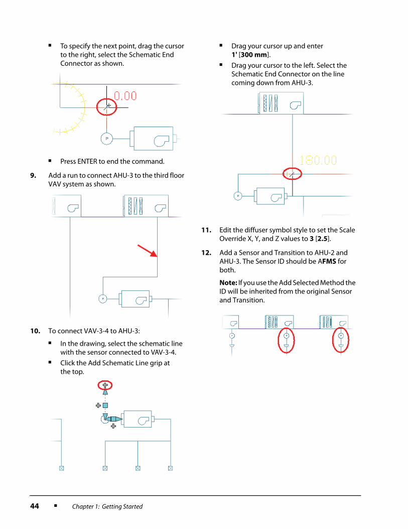
■ To specify the next point, drag the cursor to the right, select the Schematic End Connector as shown.
■ Press ENTER to end the command.
9. Add a run to connect AHU-3 to the third floor VAV system as shown.
10. To connect VAV-3-4 to AHU-3:
■ In the drawing, select the schematic line with the sensor connected to VAV-3-4.
■ Click the Add Schematic Line grip at the top.
■ Drag your cursor up and enter 1' [300 mm].
■ Drag your cursor to the left. Select the Schematic End Connector on the line coming down from AHU-3.
11. Edit the diffuser symbol style to set the Scale Override X, Y, and Z values to 3 [2.5].
12. Add a Sensor and Transition to AHU-2 and AHU-3. The Sensor ID should be AFMS for both.
Note: If you use the Add Selected Method the ID will be inherited from the original Sensor and Transition.
Lesson: Drawing a Schematic Diagram ■ 45
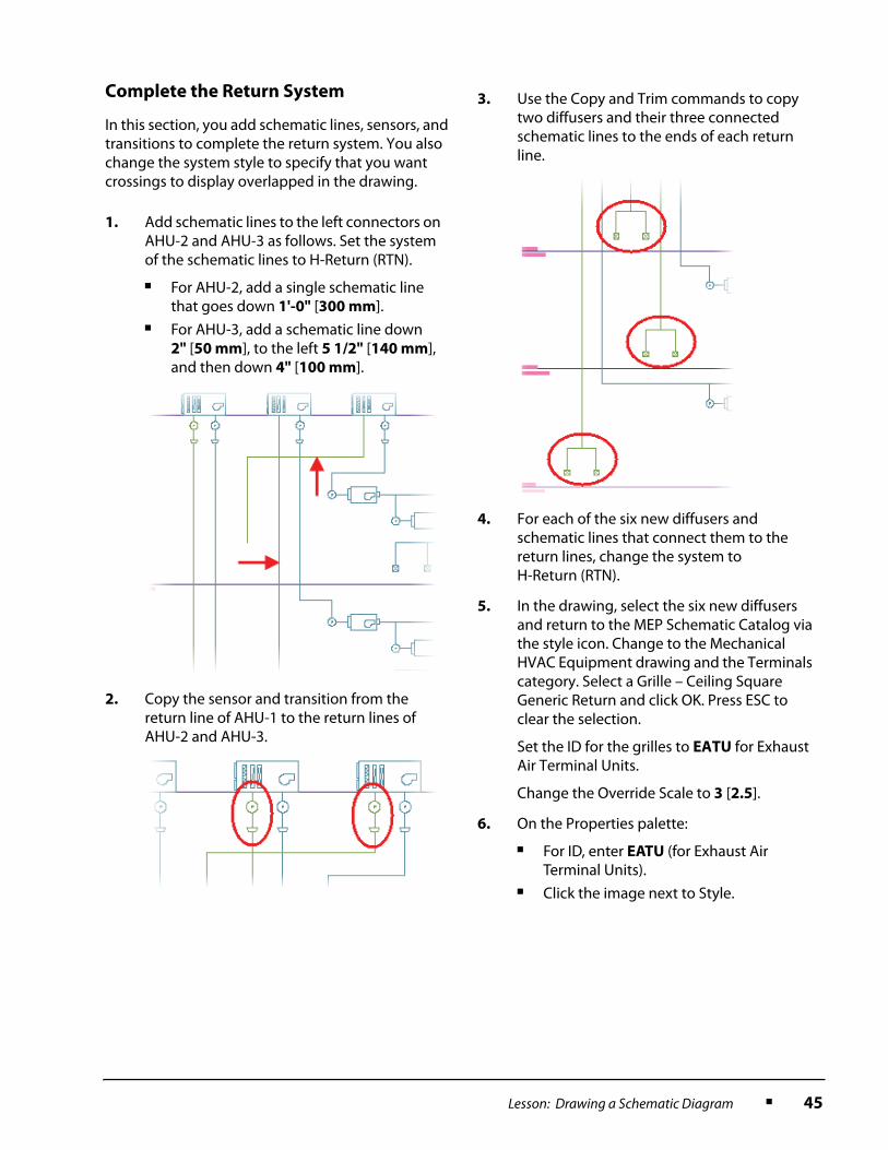
Complete the Return System
In this section, you add schematic lines, sensors, and transitions to complete the return system. You also change the system style to specify that you want crossings to display overlapped in the drawing.
1. Add schematic lines to the left connectors on AHU-2 and AHU-3 as follows. Set the system of the schematic lines to H-Return (RTN).
■ For AHU-2, add a single schematic line that goes down 1'-0" [300 mm].
■ For AHU-3, add a schematic line down 2" [50 mm], to the left 5 1/2" [140 mm], and then down 4" [100 mm].
2. Copy the sensor and transition from the return line of AHU-1 to the return lines of AHU-2 and AHU-3.
3. Use the Copy and Trim commands to copy two diffusers and their three connected schematic lines to the ends of each return line.
4. For each of the six new diffusers and schematic lines that connect them to the return lines, change the system to H-Return (RTN).
5. In the drawing, select the six new diffusers and return to the MEP Schematic Catalog via the style icon. Change to the Mechanical HVAC Equipment drawing and the Terminals category. Select a Grille – Ceiling Square Generic Return and click OK. Press ESC to clear the selection.
Set the ID for the grilles to EATU for Exhaust Air Terminal Units.
Change the Override Scale to 3 [2.5].
6. On the Properties palette:
■ For ID, enter EATU (for Exhaust Air Terminal Units).
■ Click the image next to Style.
46 ■ Chapter 1: Getting Started
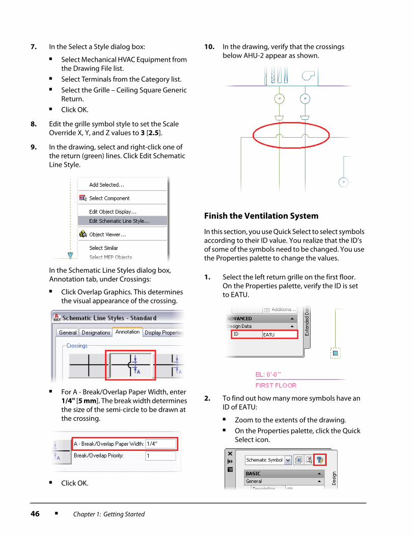
Finish the Ventilation System
In this section, you use Quick Select to select symbols according to their ID value. You realize that the ID’s of some of the symbols need to be changed. You use the Properties palette to change the values.
7. In the Select a Style dialog box:
■ Select Mechanical HVAC Equipment from the Drawing File list.
■ Select Terminals from the Category list.■ Select the Grille – Ceiling Square Generic
Return.■ Click OK.
8. Edit the grille symbol style to set the Scale Override X, Y, and Z values to 3 [2.5].
9. In the drawing, select and right-click one of the return (green) lines. Click Edit Schematic Line Style.
In the Schematic Line Styles dialog box, Annotation tab, under Crossings:
■ Click Overlap Graphics. This determines the visual appearance of the crossing.
■ For A - Break/Overlap Paper Width, enter 1/4" [5 mm]. The break width determines the size of the semi-circle to be drawn at the crossing.
■ Click OK.
10. In the drawing, verify that the crossings below AHU-2 appear as shown.
1. Select the left return grille on the first floor. On the Properties palette, verify the ID is set to EATU.
2. To find out how many more symbols have an ID of EATU:
■ Zoom to the extents of the drawing.■ On the Properties palette, click the Quick
Select icon.

Lesson: Drawing a Schematic Diagram ■ 47
3. In the Quick Select dialog box, set the following:
■ Select Entire Drawing from the Apply To list.
■ Select Schematic Symbol from the Object Type list.
■ Select ID from the Properties list.■ Select = Equals from the Operator list.■ For Value, enter EATU.■ Under How To Apply, select Include In
New Selection Set.■ Click OK.
All 6 return grills are selected because they have an ID of EATU. The right grille at the end of each return line should be set to RATU for Relief Air Terminal Units.
4. Press ESC to clear the section.
Select the three return grilles on the right (one per floor). On the Properties palette, for ID, enter RATU.
5. Save and close the drawing.

48 ■ Chapter 1: Getting Started
Lesson: Generating Spaces
Overview
This lesson describes how to generate spaces in AutoCAD MEP.
Spaces in MEP are used to model the volumes, temperature, and airflow within rooms. In the illustration below, a space labeled Women’s Restroom has been selected. The Properties palette shows airflow, heating, and cooling data associated with the space.
Objectives
After completing this lesson, you will be able to:
■ Describe the uses for and types of spaces in AutoCAD MEP.■ Describe what the Style Manager is.■ List two ways to speed up the placement of spaces.■ Generate spaces for a building.
Lesson: Generating Spaces ■ 49
Spaces
Spaces represent rooms. They enable you can to store information such as floor area, wall area, volume, occupancy, temperature, and furniture lists. You create spaces:
■ As a first step to add ceiling grids, in order to lay out fixtures such as lights, diffusers and sprinklers.■ For HVAC to analyze energy requirements, airflow, and heat and cooling characteristics of rooms
in a building model. For example, an office and a meeting room will have different energy requirements based on the number of occupants, openings, materials, and equipment in them. You model these differences using spaces.
Definition of Spaces
Spaces represent rooms, as measured from the center of one wall to the center of another, and from the base of one floor to the base of the one above, including any height below the floor or above the ceiling. A space can include openings for doors and windows, as well as ceilings.
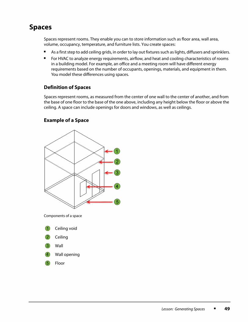
Example of a Space
Components of a space
Ceiling void
Ceiling
Wall
Wall opening
Floor
50 ■ Chapter 1: Getting Started
Space Styles
Properties of spaces that you want to reuse can be saved as space styles. For example, if you are designing a medical facility, you can create space styles for examination rooms, nurse stations, X-ray rooms, and pharmacy areas. By using styles, you do not need to specify the same properties over and over again for individual spaces.
Some properties that can be set in a space’s style include its display properties and the names (e.g. “nurse station”) that can be assigned to spaces of that type, to ensure consistency across a project.
In the Research Lab, which will use the Standard space style, spaces are shown as hatched in plan views, and with orange tags showing the space name and airflow characteristics.
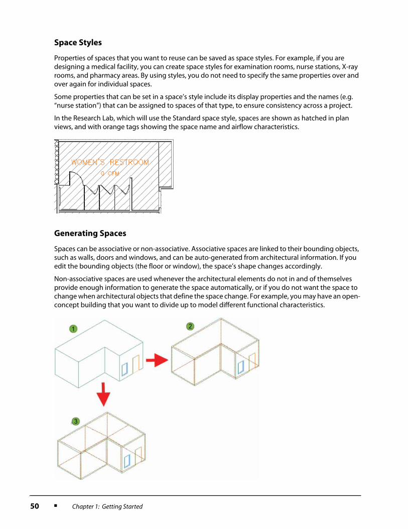
Generating Spaces
Spaces can be associative or non-associative. Associative spaces are linked to their bounding objects, such as walls, doors and windows, and can be auto-generated from architectural information. If you edit the bounding objects (the floor or window), the space’s shape changes accordingly.
Non-associative spaces are used whenever the architectural elements do not in and of themselves provide enough information to generate the space automatically, or if you do not want the space to change when architectural objects that define the space change. For example, you may have an open-concept building that you want to divide up to model different functional characteristics.

Lesson: Generating Spaces ■ 51
If you generate an associative space from the architectural plan for a room, you can either:
■ Have AutoCAD MEP extrude the x, y dimensions and shape at the floor level up to a height you define. This works for rooms that have a uniform height. You supply the thickness of the floor, the height of the ceiling, the thickness of the ceiling, and the height of the void above the ceiling, and MEP generates the space.
Shell (plan) of small open-concept retail building.
An associative space auto-generated by AutoCAD MEP for the building.
Three non-associative spaces defined by the user to delineate areas for reception, product display, and office space.
Overall space height
Height below floor
Floor thickness
Ceiling height
Ceiling thickness
Height above ceiling

52 ■ Chapter 1: Getting Started
■ If the room has a non-uniform height or irregular surfaces, you can generate a freeform space.
Style Manager
When you select an object and right-click, you can edit its style using the Edit Style command. If you change the object’s style, all objects sharing that style within the current drawing are updated accordingly. You edited both schematic symbol and line styles in this way. Although you were editing just one style at a time, you were using a small part of the power of the AutoCAD MEP Style Manager.
You can review and edit all styles in a drawing at once by using the Style Manager dialog box.
The Style Manager dialog box has two panes. The left pane lists currently open drawings. Beneath the drawing name is a list of categories of objects in the drawing, to help you find their style definitions quickly.
If you expand one of the categories, the right pane shows the styles in that category alphabetically. In the example above, the open drawing is called 01 Arch Spaces and RCP.dwg, (the drawing you will be using in the exercise in this lesson). The category Architectural Objects has been opened, in which space styles can be found.

Lesson: Generating Spaces ■ 53
Guideline for Generating Spaces
Use space name lists to standardize space names across a project. For example, if several designers are working on multiple floors of a building, or even if you are working alone on a large building, it saves time and ensures consistency if you predefine space names that will be reused such as “Main Corridor” or “Women’s Restroom”.
54 ■ Chapter 1: Getting Started
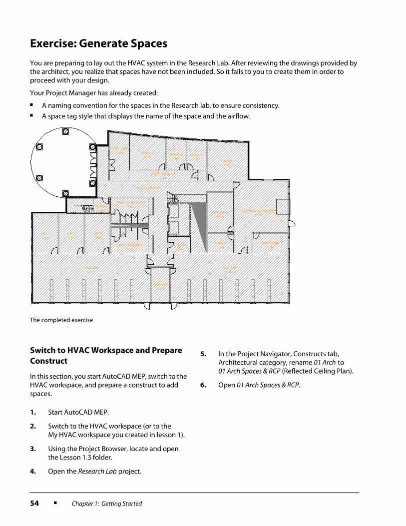
Exercise: Generate Spaces
You are preparing to lay out the HVAC system in the Research Lab. After reviewing the drawings provided by the architect, you realize that spaces have not been included. So it falls to you to create them in order to proceed with your design.
Your Project Manager has already created:
■ A naming convention for the spaces in the Research lab, to ensure consistency.■ A space tag style that displays the name of the space and the airflow.
Switch to HVAC Workspace and Prepare
Construct
In this section, you start AutoCAD MEP, switch to the HVAC workspace, and prepare a construct to add spaces.
The completed exercise
1. Start AutoCAD MEP.
2. Switch to the HVAC workspace (or to the My HVAC workspace you created in lesson 1).
3. Using the Project Browser, locate and open the Lesson 1.3 folder.
4. Open the Research Lab project.
5. In the Project Navigator, Constructs tab, Architectural category, rename 01 Arch to 01 Arch Spaces & RCP (Reflected Ceiling Plan).
6. Open 01 Arch Spaces & RCP.

Lesson: Generating Spaces ■ 55
Access Space Name List and Tag
In this section, you copy the predefined space names and tag style that the Project Manager has prepared into the current drawing.
1. On the HVAC tool palette, Analysis tab, right-click the Space tool. Click Space Styles.
2. In the left pane of the Style Manager dialog box are the currently open drawings: the default drawing Drawing1.dwg (or any other drawings you may have open), and 01 Arch Spaces and RCP.dwg.
To open the drawing in which the Project Manager has stored the predefined space names and tags, click the Open Drawing icon.
3. The Open Drawing dialog box is displayed. It enables you to move up or down the Windows hierarchy to find files.
Locate the directory for Lesson 1.3 and double-click Space.dwg.
This opens the drawing in the Style Manager only, not in the AutoCAD MEP drawing session.
4. Because you accessed the Style Manager by right-clicking a particular style (the Space style), the left pane lists only the Space style in the currently open drawings.
To see all styles in the open drawings, turn the Filter Style Type off by clicking its icon.

56 ■ Chapter 1: Getting Started
Generate Spaces
In this section, you define the spaces for the first floor. You:
■ Auto-generate the majority of the spaces from the dimensions in the floor plan and extrude them to a height you define.
■ Subdivide one of the open spaces in the floor plan into two spaces that have different usage and functional requirements.
5. To copy the space names you’ll be using from the Space.dwg to 01 Arch Spaces & RCP:
■ Expand Space.dwg.■ Under Space.dwg, expand the Multi-
Purpose Objects folder.■ Click List Definitions.■ In the right pane, right-click Commercial
Space Names. Click Copy.
6. Right-click 01 Arch Spaces & RCP. Click Paste.
The Space Names are copied into the Multi-Purpose Objects/List Definitions folder for 01 Arch Spaces & RCP. (The style information in a drawing is always organized using the same folder hierarchy.)
7. Repeat steps 5 and 6 to copy the Calc Air Flow Space tag from Space.dwg > Multi-Purpose Objects > Multi-View Block Definition to 01 Arch Spaces & RCP.
8. Right-click Space.dwg. Click Close.
9. To make the space names available for the space style you’ll be using:
■ In the left pane, under 01 Arch Spaces & RCP.dwg, expand Architectural Objects > Space Styles.
■ Click Standard.■ In the right pane, click the Design Rules
tab.■ Select Commercial Space Names from the
Space Names list.
■ Click OK to close the Style Manager.
1. In the HVAC tool palette, Analysis tab, click the Space tool.
Lesson: Generating Spaces ■ 57
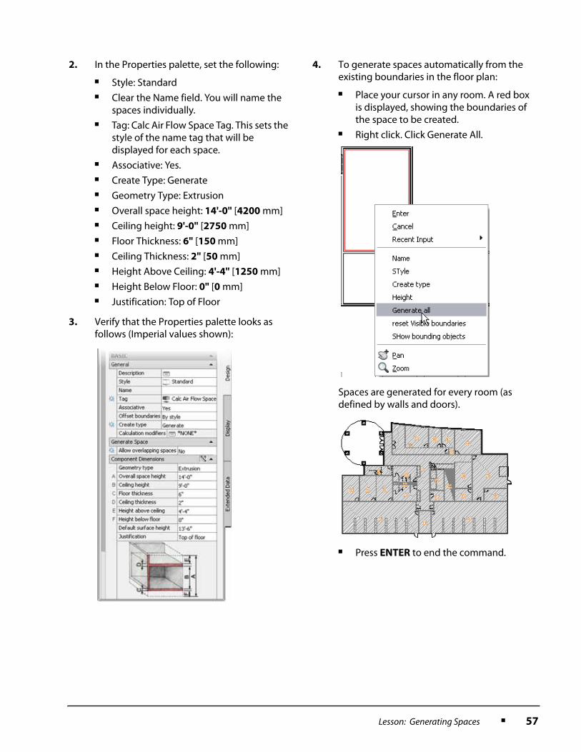
2. In the Properties palette, set the following:
■ Style: Standard■ Clear the Name field. You will name the
spaces individually.■ Tag: Calc Air Flow Space Tag. This sets the
style of the name tag that will be displayed for each space.
■ Associative: Yes.■ Create Type: Generate■ Geometry Type: Extrusion■ Overall space height: 14'-0" [4200 mm]■ Ceiling height: 9'-0" [2750 mm]■ Floor Thickness: 6" [150 mm]■ Ceiling Thickness: 2" [50 mm]■ Height Above Ceiling: 4'-4" [1250 mm]■ Height Below Floor: 0" [0 mm]■ Justification: Top of Floor
3. Verify that the Properties palette looks as follows (Imperial values shown):
4. To generate spaces automatically from the existing boundaries in the floor plan:
■ Place your cursor in any room. A red box is displayed, showing the boundaries of the space to be created.
■ Right click. Click Generate All.
Spaces are generated for every room (as defined by walls and doors).
■ Press ENTER to end the command.
58 ■ Chapter 1: Getting Started
Assign Space Names
The spaces you created have name tags that defaulted to numbers. In this section, you replace the numbers with descriptive names from the space name list provided by the Project Manager.
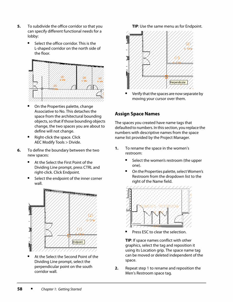
5. To subdivide the office corridor so that you can specify different functional needs for a lobby:
■ Select the office corridor. This is the L-shaped corridor on the north side of the floor.
■ On the Properties palette, change Associative to No. This detaches the space from the architectural bounding objects, so that if those bounding objects change, the two spaces you are about to define will not change.
■ Right-click the space. Click AEC Modify Tools > Divide.
6. To define the boundary between the two new spaces:
■ At the Select the First Point of the Dividing Line prompt, press CTRL and right-click. Click Endpoint.
■ Select the endpoint of the inner corner wall.
■ At the Select the Second Point of the Dividing Line prompt, select the perpendicular point on the south corridor wall.
TIP: Use the same menu as for Endpoint.
■ Verify that the spaces are now separate by moving your cursor over them.
1. To rename the space in the women’s restroom:
■ Select the women’s restroom (the upper one).
■ On the Properties palette, select Women’s Restroom from the dropdown list to the right of the Name field.
■ Press ESC to clear the selection.
TIP: If space names conflict with other graphics, select the tag and reposition it using its Location grip. The space name tag can be moved or deleted independent of the space.
2. Repeat step 1 to rename and reposition the Men’s Restroom space tag.

Lesson: Generating Spaces ■ 59
3. The space names list provided by the Project Manager is a standard list used by your company, but it does not contain names appropriate to every room in the Research Lab.
To enter unique names for the two large labs at the south end of the building:
■ Select the large space on the southeast corner of the building.
■ On the Properties palette, in the Name field, enter East Lab.
■ Rename the large space at the southwest corner of the building West Lab in the same way.
4. Repeat step 1 to name the spaces in the stairwell to the left of the restrooms, the chase between the restrooms, the elevator shaft, and the chase to the right of the elevators. Use the following names from the Name list:
■ Stairway■ Chase■ Elevator
5. To set properties for these spaces (which have in common that they have no ceiling):
■ Select the spaces for the stairwell, the two chases, and the elevator shaft.
■ On the Properties palette, Design tab, set the following in the order given:• Floor Thickness = 0
• Ceiling Thickness = 0
• Height Above Ceiling = 0
• Ceiling Height = 14'-0" [4200 mm]
The Overall Space Height is automatically recalculated as the sum of these values. It should total 14'-0" [4200 mm].
■ Press ESC to clear the selections.
6. Select the space name tags for the two chases and for the elevator and delete them.
7. Set names for the remainder of the spaces on the floor as follows (bold indicates that there is no predefined name; you have to type it):
■ The three to the left of the restrooms from left to right: Lab A, Lab B and Lab C.
■ Between the Large Labs: Supplies.■ South of the elevators: Electrical.■ To the right of the chase and above the
East Lab: Storage.■ The space above this: Mechanical.■ The large room to the right of Mechanical:
Shipping & Receiving.■ Northwest of Shipping and Receiving:
Lounge.■ The tiny space to the left of the Lounge:
Closet, but erase the tag.■ The small space below Shipping &
Receiving: S&R Office.■ The three spaces above the Closet from
left to right: Office A, Office B and Office C.
■ Below the three offices: Office Corridor.■ Below the Office Corridor: Main Corridor.■ New space to the left of Office A:
Office Lobby.
8. To create a space name tag for the Office Lobby:
■ Select the Office Corridor Tag.■ Right-click. Click Add Selected.■ Select the Lobby space.■ Click in the middle of the lobby to place
the tag.■ In the Edit Property Set Data dialog box,
click OK.■ Press ENTER to end the command.
60 ■ Chapter 1: Getting Started
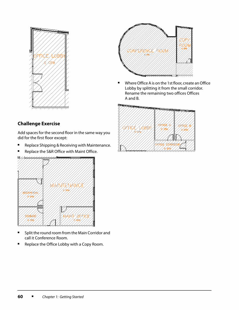
Challenge Exercise
Add spaces for the second floor in the same way you did for the first floor except:
■ Replace Shipping & Receiving with Maintenance.■ Replace the S&R Office with Maint Office.
■ Split the round room from the Main Corridor and call it Conference Room.
■ Replace the Office Lobby with a Copy Room.
■ Where Office A is on the 1st floor, create an Office Lobby by splitting it from the small corridor. Rename the remaining two offices Offices A and B.

Lesson: Working with Space Engineering Data ■ 61
Lesson: Working with Space Engineering Data
Overview
This lesson describes how to:
■ Enter space engineering data.■ Group spaces into zones.■ Import and export space engineering data that will contribute to the HVAC design of a building.
After creating spaces, you assign to each space other design data that you know, such as planned occupancy and heating loads created by lighting or other equipment.
You then group them into zones that are served by a single VAV (Variable Air Volume) device or Air Handling Unit (AHU).
Since there are many specialized HVAC analysis tools available, it is common to export your space engineering information from AutoCAD MEP, to the analysis tool of choice, and then import the results back to MEP.
The engineering data generated during this analysis can help you refine the size, strength, and properties of the HVAC equipment required for the building.
Objectives
After completing this lesson, you will be able to:
■ Enter space engineering data in AutoCAD MEP.■ Describe the use of zones in HVAC designs.■ Export space engineering data to third-party analysis software.■ Import computed engineering data from third-party analysis software.

62 ■ Chapter 1: Getting Started
Zones
Zones provide a means to organize spaces into logical groupings. For example:
■ Architects sometimes group spaces into zones based on functional requirements; for example, living versus working areas, or public versus private spaces.
■ Zones may be defined by scope; for example, construction versus demolition.■ A building may be zoned by proximity. For example, all storage spaces on a common corridor may
be grouped in a zone, or all apartments on a certain floor.■ HVAC designers typically use zones to identify spaces that are served by a single VAV box or air
handling unit. Zones defined in this way can be used to calculate airflow values for the building’s heating and cooling systems.
Zones can be defined to include both spaces and/or other zones. In HVAC designs, a zone might contain another zone if one VAV box or AHU controls other VAV boxes.
Definition of Zones
A zone is a logical grouping of two or more spaces and/or other zones.
Example of Zones
The following illustration shows the spaces in the Research Lab assigned to zones according to the VAV boxes and air handling units that serve them.

Lesson: Working with Space Engineering Data ■ 63
Green Building Extensible Markup Language
The Green Building Extensible Markup Language (gbXML) is the data format used to transfer information from building design models to engineering analysis tools and vice versa. This format is optimized to improve the energy efficiency and environmental performance of your facility.
Definition of gbXML
The gbXML data format is a variant of XML. XML is used by large Web content providers for vendor-neutral data exchange, media-independent publishing, workflow management, and many other fields. The gbXML variant has become the standard for sharing data in the building industry.
Process for Entering and Analyzing Space Engineering Data
The illustration below shows the process of creating spaces, entering space engineering data, assigning spaces to zones, exporting the data for third-party analysis, and reimporting the analysis results for review within AutoCAD MEP and for application to the final HVAC design.
Guideline for Exporting Space Engineering Data
To export space engineering data from AutoCAD MEP to a third-party application, you must group the spaces into zones. The third-party software typically needs to know which spaces are functionally related in the HVAC design.

64 ■ Chapter 1: Getting Started
Exercise: Work with Space Engineering Data
Now that you have created spaces in the Research Lab, you can use them to calculate the airflow, heating and cooling requirements.
In this exercise, you:
■ Enter space engineering data for the spaces, including details about usage, occupancy, and the presence of lighting and equipment electrical that will heat the space.
■ Group all spaces served by a single VAV box or air handling unit into zones.■ Export the engineering data for the spaces and zones for further processing using third-party
analysis software.■ Import and view the engineering data calculated by the third-party software.
Switch to HVAC Workspace and Prepare
Properties Palette
In this section, you:
■ Start AutoCAD MEP.■ Switch to the HVAC workspace.■ Use the Style Manager to make space
engineering data available on the Properties palette.
The completed exercise (zone tags shown larger than actual size)
1. Start AutoCAD MEP.
2. Switch to the HVAC workspace (or to the My HVAC workspace you created in lesson 1).
3. Using the Project Browser, locate and open the Lesson 1.4 folder.
4. Open the Research Lab project.
5. Open 01 Arch Spaces & RCP.

Lesson: Working with Space Engineering Data ■ 65
Enter Space Engineering Properties
In this section, you enter space engineering properties for the spaces:
■ You assign each space a space type. These are standard industry descriptors that come with AutoCAD MEP so that space engineering data can be shared with third-party applications.
■ You enter occupancy, airflow, lighting and equipment load information.
6. On the HVAC tool palette, Analysis tab, right-click the Space tool. Click Space Styles.
7. To see all styles in the open drawing, turn the Filter Style Type off.
8. To activate the Space Types field on the Properties palette for space styles:
■ In the left pane under Architectural Objects, expand Documentation Objects > Property Set Definitions.
■ Click SpaceEngineeringObjects.
■ In the right pane, Definition tab, click the Visible check box for Space Type.
■ Click OK to close the Style Manager.
1. To define the space type for the labs:
■ Select all five labs.■ On the Properties palette, Extended Data
tab, under Property Sets > SpaceEngineeringObjects > Space Type, select LABORATORYOFFICE from the list.
■ Press ESC to clear the selections.
2. Repeat step 1 to set the following Space Types for the remaining spaces:
■ Both Restrooms: RESTROOMS.■ Stairway: STAIRWAY.■ Supplies and Storage: ACTIVESTORAGE.■ Electrical and Mechanical:
ELECTRICALORMECHANICAL.■ Shipping & Receiving:
WORKSHOPWORKSHOP.■ Lounge: LOUNGEORRECREATION.

66 ■ Chapter 1: Getting Started
■ All four Offices: OFFICEENCLOSED.■ Both Corridors:
CORRIDORORTRANSITION.■ Office Lobby: LOBBY.
3. To set the Space Engineering Objects properties for Labs A, B, and C:
■ Select Labs A, B, and C.■ On the Properties palette, Extended Data
tab, under Property Sets > SpaceEngineeringObjects, set the following:
• Occupancy: 4
• OutsideAirFlow: 25 [12]
• SupplyAirFlow: 125 [60]
• LightingLoad: 700
• EquipmentLoad: 1500
■ Notice that the Space Engineering Calculated Data properties in the lower part of the Extended Design tab are blank. These will be calculated by third-party software when you have finished entering the Space Engineering Objects properties for all spaces on the floor.
■ Press ESC to deselect the labs.
4. Time permitting, repeat step 3 for the other spaces.
East and West Labs:
■ Occupancy: 20
■ OutsideAirFlow: 2800 [1325]■ SupplyAirFlow: 1800 [850]■ LightingLoad: 3000
■ EquipmentLoad: 10000
Women’s Restroom:
■ Occupancy: 4■ OutsideAirFlow: 30 [15]■ SupplyAirFlow: 150 [70]■ LightingLoad: 500
■ EquipmentLoad: 1500
Men’s Restroom:
■ Occupancy: 4■ OutsideAirFlow: 50 [25]■ SupplyAirFlow: 215 [100]■ LightingLoad: 500
■ EquipmentLoad: 1500
Supplies and Storage:
■ Occupancy: 0■ OutsideAirFlow: 5 [3]■ SupplyAirFlow: 20 [10]■ LightingLoad: 500
■ EquipmentLoad: 0
Stairway:
■ Occupancy: 130
■ OutsideAirFlow: 20 [10]■ SupplyAirFlow: 100 [50]■ LightingLoad: 2000
■ EquipmentLoad: 0
5. Main Corridor:
■ Occupancy: 130
■ OutsideAirFlow: 350 [165]■ SupplyAirFlow: 1600 [755]■ LightingLoad: 2000
■ EquipmentLoad: 0
Office Lobby:
■ Occupancy: 6■ OutsideAirFlow: 25 [12]■ SupplyAirFlow: 125 [60]■ LightingLoad: 700
■ EquipmentLoad: 900
Office A:
■ Occupancy: 4■ OutsideAirFlow: 50 [25]■ SupplyAirFlow: 250 [120]■ LightingLoad: 700
■ EquipmentLoad: 900

Lesson: Working with Space Engineering Data ■ 67
Assign Spaces to Zones
In this section, you assign spaces to zones.
Offices B and C, and S&R Office:
■ Occupancy: 2■ OutsideAirFlow: 15 [7]■ SupplyAirFlow: 75 [35]■ LightingLoad: 700
■ EquipmentLoad: 900
6. Office Corridor:
■ Occupancy: 10
■ OutsideAirFlow: 50 [25]■ SupplyAirFlow: 250 [120]■ LightingLoad: 700
■ EquipmentLoad: 0
Lounge:
■ Occupancy: 12
■ OutsideAirFlow: 50 [25]■ SupplyAirFlow: 250 [120]■ LightingLoad: 700
■ EquipmentLoad: 1500
Shipping & Receiving:
■ Occupancy: 4■ OutsideAirFlow: 50 [25]■ SupplyAirFlow: 270 [125]■ LightingLoad: 2000
■ EquipmentLoad: 1500
7. Electrical:
■ Occupancy: 2■ OutsideAirFlow: 15 [7]■ SupplyAirFlow: 75 [35]■ LightingLoad: 500
■ EquipmentLoad: 1500
Mechanical:
■ Occupancy: 2■ OutsideAirFlow: 20 [10]■ SupplyAirFlow: 100 [50]■ LightingLoad: 700
■ EquipmentLoad: 10000
1. To place zones:
■ On the HVAC tool palette, Analysis tab, click Zone.
■ Move your cursor to location 1 as shown.■ Click to place a zone.
■ The zone placement command is still active. Click once to place each zone around the drawing in the sequence and locations shown.
■ Press ENTER to end the command.

68 ■ Chapter 1: Getting Started
2. If you zoom in, you’ll see that the zones have been numbered, except for the first one. To rename the first zone you placed:
■ Select it.■ On the Properties palette, Design tab,
change the Name to Zone (1). This will automatically number all of the zones you placed.
■ Deselect Zone (1).
3. To assign the West Lab to Zone (2):
■ Select Zone (2).■ Select its Attach Space or Zone Grip.
■ Select the West Lab.■ Press ENTER.
4. Repeat step 3 to assign the East Lab to Zone (3).
5. Since the VAV boxes or air handling units for the two largest labs may be served by a third VAV box or air handling unit (the final design pending analysis by third-party software), Zone (1) will include Zones (2) and (3).
To assign Zones (2) and (3) to Zone (1):
■ Select Zone (1).■ Select the Attach Space or Zone Grip on
Zone (1).■ Select Zone (2) and Zone (3).■ Press ENTER (zone tags shown larger than
actual size for legibility).
6. Assign the remaining spaces to zones as follows:
■ Zone (4): Main Corridor, Supplies and Electrical.
■ Zone (5): Labs A, B, and C.■ Zone (6): Stairway.■ Zone (7): Both restrooms.■ Zone (8): Office Lobby, Offices A, B and C,
Lounge and Office Corridor.■ Zone (9): Shipping & Receiving, S&R
Office, Mechanical and Storage.
7. Save and close the drawing.
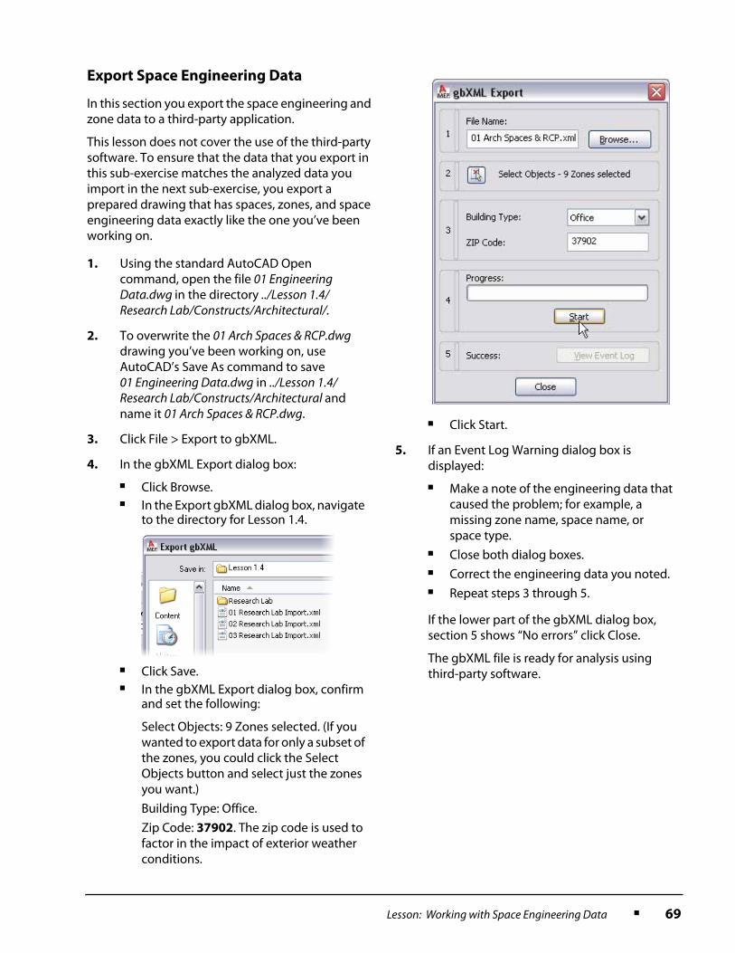
Lesson: Working with Space Engineering Data ■ 69
Export Space Engineering Data
In this section you export the space engineering and zone data to a third-party application.
This lesson does not cover the use of the third-party software. To ensure that the data that you export in this sub-exercise matches the analyzed data you import in the next sub-exercise, you export a prepared drawing that has spaces, zones, and space engineering data exactly like the one you’ve been working on.
1. Using the standard AutoCAD Open command, open the file 01 Engineering Data.dwg in the directory ../Lesson 1.4/Research Lab/Constructs/Architectural/.
2. To overwrite the 01 Arch Spaces & RCP.dwg drawing you’ve been working on, use AutoCAD’s Save As command to save 01 Engineering Data.dwg in ../Lesson 1.4/Research Lab/Constructs/Architectural and name it 01 Arch Spaces & RCP.dwg.
3. Click File > Export to gbXML.
4. In the gbXML Export dialog box:
■ Click Browse.■ In the Export gbXML dialog box, navigate
to the directory for Lesson 1.4.
■ Click Save.■ In the gbXML Export dialog box, confirm
and set the following:
Select Objects: 9 Zones selected. (If you wanted to export data for only a subset of the zones, you could click the Select Objects button and select just the zones you want.)
Building Type: Office.
Zip Code: 37902. The zip code is used to factor in the impact of exterior weather conditions.
■ Click Start.
5. If an Event Log Warning dialog box is displayed:
■ Make a note of the engineering data that caused the problem; for example, a missing zone name, space name, or space type.
■ Close both dialog boxes.■ Correct the engineering data you noted.■ Repeat steps 3 through 5.
If the lower part of the gbXML dialog box, section 5 shows “No errors” click Close.
The gbXML file is ready for analysis using third-party software.

70 ■ Chapter 1: Getting Started
Import Space Engineering Data
In this section, you import engineering data via a gbXML file that has been analyzed using third-party software.
Challenge Exercise
Add zones and space engineering data for the second floor in the same way as you did for the first floor except:
■ Set the space engineering properties for the spaces as per the first floor except:
• Office Lobby
- Occupancy: 10
- OutsideAirFlow: 50 [25]
- SupplyAirFlow: 250 [120]
- LightingLoad: 700
- EquipmentLoad: 900
• Copy Room
- SpaceType: SortingAreaPostOffice
- Occupancy: 4
- OutsideAirFlow: 25 [12]
- SupplyAirFlow: 125 [60]
- LightingLoad: 700
- EquipmentLoad: 5000
• Conference Room
- SpaceType: ConferenceMeetingOrMultipurpose
- Occupancy: 30
- OutsideAirFlow: 180 [85]
- SupplyAirFlow: 900 [425]
- LightingLoad: 2000
- EquipmentLoad: 900
■ A few of the rooms have been renamed on the second floor. Include them in the same zones as their counterparts on the first floor.
■ Place the round Conference Room (which doesn’t exist on the first floor) in a zone by itself. Name it Zone (8) and renumber the two zones clockwise Zones (9) and (10).
1. Click File > Import from gbXML.
2. In the Import gbXML dialog box:
■ Navigate to the directory for Lesson 1.4.■ Open 01 Research Lab Import.xml.
3. To regenerate the model and update all open drawings:
■ Click the Regenerate Model icon at the right end of the Standard tool bar.
■ At the Select Objects prompt, press ENTER to regenerate all objects.
4. To check that the import has been successful:
■ Select any space and examine the Space Engineering Calculated Data properties at the bottom of the Properties palette, Extended Data tab.
For the sake of this exercise, three have been imported. Depending on the third-party analysis software you use, you may obtain more.
■ Zoom in on one of the space tags. The CFM has been updated to reflect the values in the imported data.
5. Save and close the drawing.

Lesson: Adding Ceiling Grids ■ 71
Lesson: Adding Ceiling Grids
Overview
This lesson describes how to add ceiling grids in AutoCAD MEP.
While ceiling grids are predominantly architectural objects, you need to know how they work to use them in AutoCAD MEP.
Ceiling grids in MEP represent dropped ceilings and ceiling tiles in the real world. You create ceiling grids to precisely attach items such as lights, diffusers and sprinklers. The following illustration shows a space (dotted boundary) in which a ceiling grid has been placed, with attached diffusers.
Objectives
After completing this lesson, you will be able to:
■ Explain how ceiling grids are implemented within AutoCAD MEP.■ Describe how you can use display configurations to view objects in the most useful combinations.■ List two tips for placing ceiling grids.■ Add ceiling grids.
Space boundary
Ceiling grid lines
Diffusers

72 ■ Chapter 1: Getting Started
Ceiling Grids
You use ceiling grids to position and attach electrical and mechanical objects. Ceiling grids in AutoCAD MEP model actual ceiling grids and ceiling tiles in the real world.
Definition of Ceiling Grids
A ceiling grid in AutoCAD MEP is an arrangement of crossing parallel lines that define rectangular spaces called bays.
The following illustration shows the important dimensions in a ceiling grid.
Layout Type
The layout type of a ceiling grid determines the number and size of bays.
X width Overall width of the ceiling grid.
Y depth Overall depth of the ceiling grid.
X bay size Width between two consecutive junctions along the x-axis.
Y bay size Width between two consecutive junctions along the y-axis.
Layout Type Description
Repeat The bay size is fixed. The total number of bays depends on the total dimensions of the grid.
Space Evenly The number of bays is fixed, but their size is not. The size of the bays depends on the total dimensions of the grid.

Lesson: Adding Ceiling Grids ■ 73
The left ceiling grid below has been added to a 10' x 12' space using a layout type of Repeat. The bay size is fixed at 2" x 2", so there are 30 bays in all.
The right ceiling grid has been added to the same space using a layout type of Space Evenly. The number of bays has been fixed at 6 in the x direction and 7 in the y direction, yielding 42 bays in all with non-standard dimensions just under 2" x 2".
If the dimensions of a space are not an exact multiple of a standard ceiling tile size, a layout type of Repeat often produces partial tiles around the edge of the space. A layout type of Space Evenly will never yield partial bays, but may produce non-standard bay sizes.
Layout Type: Repeat
Layout Type: Space Evenly

74 ■ Chapter 1: Getting Started
Example of a Ceiling Grid
The following illustration shows an example of a building with several ceiling grids.
Note:
■ Bays can have different sizes and orientations, depending on the space.■ The room at the northeast corner of the building has had a hole cut in the ceiling grid
to allow for a skylight.
Holes
You add holes to a ceiling grid to represent openings in the real world. For example, you create a hole in a ceiling grid to specify the location of a stair passing from one floor to another, or for a skylight.
You can add a hole of any shape to a ceiling grid. You draw a closed polyline using standard AutoCAD tools and convert it to a hole.
Example of a hole
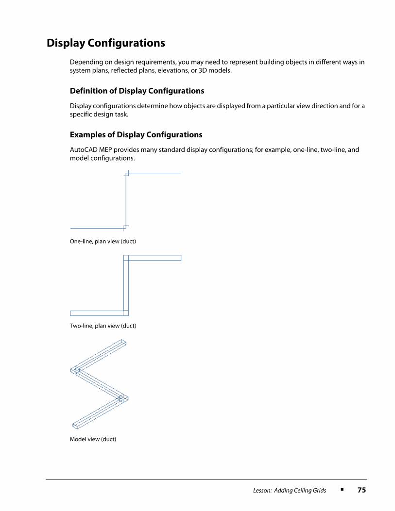
Lesson: Adding Ceiling Grids ■ 75
Display Configurations
Depending on design requirements, you may need to represent building objects in different ways in system plans, reflected plans, elevations, or 3D models.
Definition of Display Configurations
Display configurations determine how objects are displayed from a particular view direction and for a specific design task.
Examples of Display Configurations
AutoCAD MEP provides many standard display configurations; for example, one-line, two-line, and model configurations.
One-line, plan view (duct)
Two-line, plan view (duct)
Model view (duct)

76 ■ Chapter 1: Getting Started
The display configuration is what makes architectural objects such as walls, doors and windows appear as a grey screen in all out-of-the-box MEP configurations and in full color in the Standard configuration. The Mechanical configurations enable the HVAC designer to view electrical objects in a grey screen so that the HVAC objects will stand out in full color while the Electrical configurations do the opposite.
Display configurations are similar to saving layer states or to turning layers on and off in AutoCAD. The difference is that with display configurations, you have much more power and flexibility. You can control the appearance of objects not just by layer but also by view angle (plan, elevation or model), type (single-line, double-line, solid-fill, cut planes), style (pipe, duct, device, space, stair, wall) or by individual object via an object override.
In the following illustrations, different display configurations are applied to the Research Lab. Both views are in Top or Plan view. In the first illustration, the MEP Design display configuration is applied and in the second the Mechanical display configuration is applied. The diagonally hatched spaces and ceiling grids appear in the MEP Design configuration but they do not appear in the Mechanical configuration. The space tag appears in both.
Display configuration: MEP Design

Lesson: Adding Ceiling Grids ■ 77
Guidelines for Adding Ceiling Grids
Following these guidelines will assist you to add ceiling grids.
Use a Display Configuration such as MEP Design
Since ceiling grids are not visible in all display configurations, change to a display configuration such as MEP Design, which comes out of the box with AutoCAD MEP.
Add Ceiling Grids to Spaces
Buildings must have spaces defined before you can add ceiling grids.
Display configuration: Mechanical
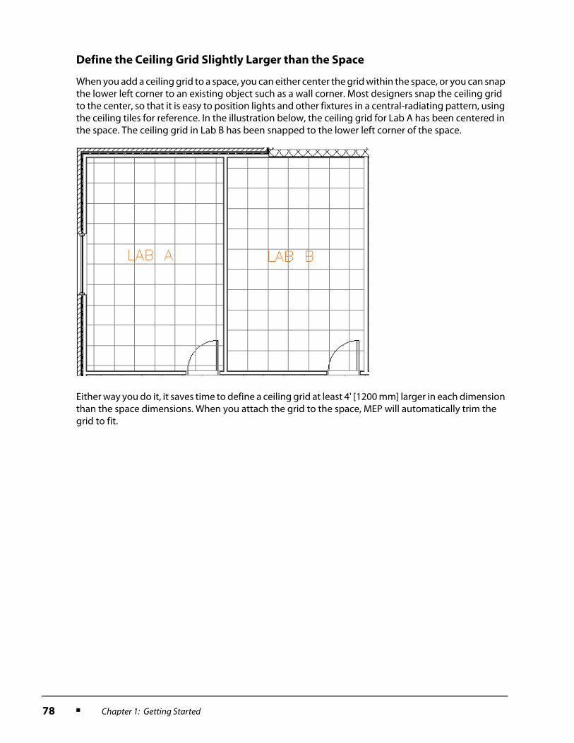
78 ■ Chapter 1: Getting Started
Define the Ceiling Grid Slightly Larger than the Space
When you add a ceiling grid to a space, you can either center the grid within the space, or you can snap the lower left corner to an existing object such as a wall corner. Most designers snap the ceiling grid to the center, so that it is easy to position lights and other fixtures in a central-radiating pattern, using the ceiling tiles for reference. In the illustration below, the ceiling grid for Lab A has been centered in the space. The ceiling grid in Lab B has been snapped to the lower left corner of the space.
Either way you do it, it saves time to define a ceiling grid at least 4' [1200 mm] larger in each dimension than the space dimensions. When you attach the grid to the space, MEP will automatically trim the grid to fit.

Lesson: Adding Ceiling Grids ■ 79
Exercise: Add Ceiling Grids
You are preparing to lay out the HVAC system in the Research Lab. After reviewing the drawings provided by the architect, you realize that the ceiling grids are not included. So it falls to you to add the ceiling grids in order to proceed with your design.
In this exercise, you:
■ Add ceiling grids to the spaces in the Research Lab.■ Remove a hole in the ceiling grid for stairs.
Prepare to Add Ceiling Grids
In this section, you:
■ Start AutoCAD MEP.■ Switch to the Architectural workspace.■ Open the construct that shows the spaces in the
Research Lab.■ Set the display configuration to MEP Design so
that you will be able to see ceiling grids.
The completed exercise
1. Start AutoCAD MEP.
2. On the Workspaces toolbar, select Architectural from the list.

80 ■ Chapter 1: Getting Started
Add Ceiling Grids
In this section, you attach ceiling grids to the three largest spaces in the Research Lab.
3. Using the Project Browser, locate and open the Lesson 1.6 folder.
4. Open the Research Lab project.
5. Open 01 Arch Spaces & RCP.
6. By default, you have been working with a display configuration of MEP Basic 2-Line.
To see ceiling grids, on the Drawing Window Status Bar, click MEP Basic 2-Line > MEP Design.
1. On the Architectural tool palette, Design Tab, click Ceiling Grid.
2. On the Properties palette, under Dimensions, set:
■ X-Width: 70'-0" [21000 mm]■ Y-Depth: 34'-0" [10000 mm]■ Under X Axis:
• Layout type: Repeat
• Bay Size: 2'-0" [600mm]
■ Under Y Axis:
• Layout type: Repeat
• Bay Size: 4'-0" [1200 mm]
This creates a ceiling grid slightly larger than the large labs.
3. To select the space to which to attach the ceiling grid:
■ Move the cursor into the drawing area.■ Right-click. Click Set boundary.
■ Select one of the large lab spaces. As you move the cursor, the ceiling grid moves within the confines of the space you selected.
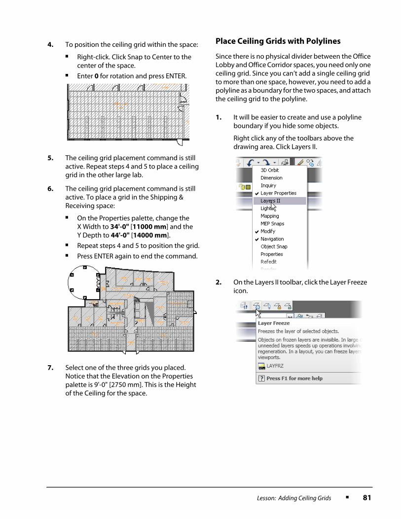
Lesson: Adding Ceiling Grids ■ 81
Place Ceiling Grids with Polylines
Since there is no physical divider between the Office Lobby and Office Corridor spaces, you need only one ceiling grid. Since you can’t add a single ceiling grid to more than one space, however, you need to add a polyline as a boundary for the two spaces, and attach the ceiling grid to the polyline.
4. To position the ceiling grid within the space:
■ Right-click. Click Snap to Center to the center of the space.
■ Enter 0 for rotation and press ENTER.
5. The ceiling grid placement command is still active. Repeat steps 4 and 5 to place a ceiling grid in the other large lab.
6. The ceiling grid placement command is still active. To place a grid in the Shipping & Receiving space:
■ On the Properties palette, change the X Width to 34'-0" [11000 mm] and the Y Depth to 44'-0" [14000 mm].
■ Repeat steps 4 and 5 to position the grid.■ Press ENTER again to end the command.
7. Select one of the three grids you placed. Notice that the Elevation on the Properties palette is 9'-0" [2750 mm]. This is the Height of the Ceiling for the space.
1. It will be easier to create and use a polyline boundary if you hide some objects.
Right click any of the toolbars above the drawing area. Click Layers II.
2. On the Layers II toolbar, click the Layer Freeze icon.
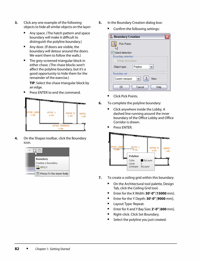
82 ■ Chapter 1: Getting Started
3. Click any one example of the following objects to hide all similar objects on the layer:
■ Any space. (The hatch pattern and space boundary will make it difficult to distinguish the polyline boundary.)
■ Any door. (If doors are visible, the boundary will detour around the doors. We want them to follow the walls.)
■ The grey-screened triangular block in either chase. (The chase blocks won’t affect the polyline boundary, but it’s a good opportunity to hide them for the remainder of the exercise.)
TIP: Select the chase triangular block by an edge.
■ Press ENTER to end the command.
4. On the Shapes toolbar, click the Boundary icon.
5. In the Boundary Creation dialog box:
■ Confirm the following settings:
■ Click Pick Points.
6. To complete the polyline boundary:
■ Click anywhere inside the Lobby. A dashed line running around the inner boundary of the Office Lobby and Office Corridor is drawn.
■ Press ENTER.
7. To create a ceiling grid within this boundary:
■ On the Architectural tool palette, Design Tab, click the Ceiling Grid tool.
■ Enter for the X Width: 50'-0" [15000 mm].■ Enter for the Y Depth: 30'-0" [9000 mm].■ Layout Type: Repeat.■ Enter for X and Y Bay Size: 2'-0" [600 mm].■ Right-click. Click Set Boundary.■ Select the polyline you just created.

Lesson: Adding Ceiling Grids ■ 83
8. Depending on how AutoCAD defined the polyline with the arc in the wall, snapping to center can sometimes produce unexpected results. To avoid this, place the ceiling grid at the endpoint in the corner of the wall with a rotation of 0.
9. Since polylines do not store the ceiling height property:
■ Select the ceiling grid.■ On the Properties palette, under
Location, change the Elevation to 9'-0" [2750 mm].
■ Press ESC to deselect the grid.
10. To move the polyline to a hidden layer that will not plot:
■ Select the polyline.■ Select G-Risr-Std-Nplt from the Layer
Control list.
■ When prompted, click OK to confirm that you want to move the polyline to a frozen non-plot layer.
11. To make the doors and spaces visible again:
■ Click the Layer Properties Manager icon.
■ In the Layer Properties Manager dialog box, click the Freeze icons for 1st Floor|A-Door [1st Floor|A315G] and G-Spce to thaw the layers.
12. To screen the space tags, change the color of layer G-Spce-Std-Iden to 9.
13. Since the CFM information on the space tags is significant only to HVAC, freeze layer G-Zone-Std.
14. To save your changes:
■ Click the Layer States Manager icon.
■ Clear the Turn Off Layers Not Found in Layer State check box.
■ Click Save to save the Screened layer state.
■ Click Yes when prompted Overwrite Selected Layer State.
■ Click Restore to exit the Layer State Manager dialog box.
■ Click OK to save your changes and exit the Layer Properties dialog box.

84 ■ Chapter 1: Getting Started
Add the Remaining Ceiling Grids and a
Hole for the Stairs
In this section, you add the remaining ceiling grids and cut a hole in the grid at the stairs above the elevator to represent the opening for the floor-to-floor passage.
To save time and ensure accuracy creating the identical hole on multiple floors, a co-worker has drawn the dimensions of the hole and saved it as a block.
1. Add ceiling grids to the remaining rooms, not including the stairway, the elevator, and the chases:
■ Make the bays 2'-0" x 2'-0" [600 mm x 600 mm], Layout Type: Repeat.
■ Make the X Width and Y Depth at least 4'-0" [1200 mm] larger than each space’s Actual Dimensions, as given on the Properties palette, Design tab.
■ Snap to Center for all grids.■ Enter a rotation of 0 for all grids.
2. To load the block representing the hole:
■ Click Insert > Block.■ In the Insert dialog box, click Browse.■ Locate the drawing Hole.dwg. Click Open.■ Confirm that only the Explode check box
is selected, as shown.
■ Click OK.
The block is exploded into a polyline.
3. To create the hole in the grid:
■ Select the ceiling grid at the stairs (for the Main Corridor).
■ Right-click. Click Clip.
4. To complete the hole in the grid:
■ Right click again. Click Add Hole.
■ Select the polyline outline of the hole you inserted.
■ Press ENTER to end the command.
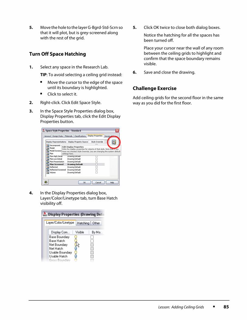
Lesson: Adding Ceiling Grids ■ 85
Turn Off Space Hatching
Challenge Exercise
Add ceiling grids for the second floor in the same way as you did for the first floor.
5. Move the hole to the layer G-Bgrd-Std-Scrn so that it will plot, but is grey-screened along with the rest of the grid.
1. Select any space in the Research Lab.
TIP: To avoid selecting a ceiling grid instead:
■ Move the cursor to the edge of the space until its boundary is highlighted.
■ Click to select it.
2. Right-click. Click Edit Space Style.
3. In the Space Style Properties dialog box, Display Properties tab, click the Edit Display Properties button.
4. In the Display Properties dialog box, Layer/Color/Linetype tab, turn Base Hatch visibility off.
5. Click OK twice to close both dialog boxes.
Notice the hatching for all the spaces has been turned off.
Place your cursor near the wall of any room between the ceiling grids to highlight and confirm that the space boundary remains visible.
6. Save and close the drawing.

86 ■ Chapter 1: Getting Started
Chapter Summary
In this chapter, you learned to:
■ Load base drawings for a project.■ Draw a schematic diagram.■ Generate spaces.■ Work with space engineering data.■ Add ceiling grids.