getting started guide - trimble · operation is subject to the ... the snm910 cellular modem...
TRANSCRIPT

GETTING STARTED GUIDE
SNM910 CELLULAR MODEM
Version 4.17 Revision A September 2010 F

2 SNM910 Cellular Modem Getting Started Guide
Legal NoticesCorporate Office Trimble Navigation Limited 935 Stewart Drive Sunnyvale, CA 94085 USA www.trimble.com Heavy Highway business area Trimble Navigation Limited Heavy Highway business area 5475 Kellenburger Road Dayton, Ohio 45424-1099 USA 800-538-7800 (toll free in USA) +1-937-245-5600 Phone +1-937-233-9004 Fax www.trimble.com E-mail: [email protected] Legal Notices © 2006–2010, Trimble Navigation Limited. All rights reserved. Trimble, the Globe & Triangle logo, and TSC2 are trademarks of Trimble Navigation Limited, registered in the United States and in other countries. AutoBase, CMR, CMR+, EVEREST, HYDROpro, Maxwell, Micro-Centered, Trimble Geomatics Office, SiteNet, TRIMMARK, TRIMTALK, TSCe, VRS, Zephyr, and Zephyr Geodetic are trademarks of Trimble Navigation Limited. The Bluetooth word mark and logos are owned by the Bluetooth SIG, Inc. and any use of such marks by Trimble Navigation Limited is under license. Microsoft, Windows, and Windows NT are either registered trademarks or trademarks of Microsoft Corporation in the United States and/or other countries.All other trademarks are the property of their respective owners. NTP Software Copyright © David L. Mills 1992-2009. Permission to use, copy, modify, and distribute this software and its documentation for any purpose with or without fee is hereby granted, provided that the above copyright notice appears in all copies and that both the copyright notice and this permission notice appear in supporting documentation, and that the name University of Delaware not be used in advertising or publicity pertaining to distribution of the software without specific, written prior permission. The University of Delaware makes no representations about the suitability this software for any purpose. It is provided "as is" without express or implied warranty. Product Limited Warranty Information For applicable product Limited Warranty information, please refer to the Limited Warranty Card included with this Trimble product, or consult your local Trimble authorized dealer. COCOM limits The U.S. Department of Commerce requires that all exportable GPS products contain performance limitations so that they cannot be used in a manner that could threaten the security of the United States. The following limitations are implemented on this product:
• Immediate access to satellite measurements and navigation results is disabled when the receiver velocity is computed to be greater than 1,000 knots, or its altitude is computed to be above 18,000 meters. The receiver GPS subsystem resets until the COCOM situation clears. As a result, all logging and stream configurations stop until the GPS subsystem is cleared.
Notices Class B Statement – Notice to Users. This equipment has been tested and found to comply with the limits for a Class B digital device, pursuant to Part 15 of the FCC rules and Part 90. These limits are designed to provide reasonable protection against harmful interference in a residential installation. This equipment generates, uses, and can radiate radio frequency energy and, if
not installed and used in accordance with the instructions, may cause harmful interference to radio communication. However, there is no guarantee that interference will not occur in a particular installation. If this equipment does cause harmful interference to radio or television reception, which can be determined by turning the equipment off and on, the user is encouraged to try to correct the interference by one or more of the following measures:
• Reorient or relocate the receiving antenna.
• Increase the separation between the equipment and the receiver.
• Connect the equipment into an outlet on a circuit different from that to which the receiver is connected.
• Consult the dealer or an experienced radio/TV technician for help.
Changes and modifications not expressly approved by the manufacturer or registrant of this equipment can void your authority to operate this equipment under Federal Communications Commission rules. Canada This Class B digital apparatus complies with Canadian ICES-003. Cet appareil numérique de la classe B est conforme à la norme NMB-003 du Canada. This apparatus complies with Canadian RSS-GEN, RSS-310, RSS-210, and RSS-119. Cet appareil est conforme à la norme CNR-GEN, CNR-310, CNR-210, et CNR-119 du Canada. Europe The product covered by this guide are intended to be used in all EU member countries, Norway, and Switzerland. Products been tested and found to comply with the requirements for a Class B device pursuant to European Council Directive 89/336/EEC on EMC, thereby satisfying the requirements for CE Marking and sale within the European Economic Area (EEA). Contains a Bluetooth radio module. These requirements are designed to provide reasonable protection against harmful interference when the equipment is operated in a residential or commercial environment. The 450 MHZ (PMR) bands and 2.4 GHz are non-harmonized throughout Europe. CE Declaration of Conformity Hereby, Trimble Navigation, declares that the GPS receivers are in compliance with the essential requirements and other relevant provisions of Directive 1999/5/EC. Australia and New Zealand This product conforms with the regulatory requirements of the Australian Communications and Media Authority (ACMA) EMC framework, thus satisfying the requirements for C-Tick Marking and sale within Australia and New Zealand. Restriction of Use of Certain Hazardous Substances in Electrical and Electronic Equipment (RoHS) Trimble products in this guide comply in all material respects with DIRECTIVE 2002/95/EC OF THE EUROPEAN PARLIAMENT AND OF THE COUNCIL of 27 January 2003 on the restriction of the use of certain hazardous substances in electrical and electronic equipment (RoHS Directive) and Amendment 2005/618/EC filed under C(2005) 3143, with exemptions for lead in solder pursuant to Paragraph 7 of the Annex to the RoHS Directive applied. Waste Electrical and Electronic Equipment (WEEE) For product recycling instructions and more information, please go to www.trimble.com/ev.shtml.

SNM910 Cellular Modem Getting Started Guide 3
Recycling in Europe: To recycle Trimble WEEE (Waste Electrical and Electronic Equipment, products that run on electrical power.), Call +31 497 53 24 30, and ask for the “WEEE Associate”. Or, mail a request for recycling instructions to: Trimble Europe BV c/o Menlo Worldwide Logistics Meerheide 45 5521 DZ Eersel, NL
FCC Declaration of Conformity We, Trimble Navigation Limited.
935 Stewart Drive PO Box 3642
Sunnyvale, CA 94088-3642 United States
+1-408-481-8000 Declare under sole responsibility that DoC products comply with
Part 15 of FCC Rules. Operation is subject to the following two conditions:
(1) This device may not cause harmful interference, and (2) This device must accept any interference received, including
interference that may cause undesired operation Unlicensed radios in products This device complies with part 15 of the FCC Rules. Operation is subject to the following two conditions: (1) This device may not cause harmful interference, and (2) This device must accept any interference received, including interference that may cause undesired operation. Licensed radios in products This device complies with part 15 of the FCC Rules. Operation is subject to the condition that this device may not cause harmful interference.

4 SNM910 Cellular Modem Getting Started Guide
Safety Information Before you use your Trimble product, make sure that you have read and understood all safety requirements.
Use and care This product is designed to withstand the rough treatment and tough environment that typically occurs in construction applications. However, the receiver is a high-precision electronic instrument and should be treated with reasonable care.
Caution – Operating or storing the receiver outside the specified temperature range can damage it.
Regulations and safety The SNM910 cellular modem contains an internal Quad-Band GSM 850/900/1800/1900MHz radio modem.
Before operating a Trimble GPS receiver or GSM modem, determine if authorization or a license to operate the unit is required in your country. It is the responsibility of the end user to obtain an operator's permit or license for the receiver for the location or country of use.
For FCC regulations, see Legal Notices.
Type approval Type approval, or acceptance, covers technical parameters of the equipment related to emissions that can cause interference. Type approval is granted to the manufacturer of the transmission equipment, independent from the operation or licensing of the units. Some countries have unique technical requirements for operation in particular radio-modem frequency bands. To comply with those requirements, Trimble may have modified your equipment to be granted Type approval.
Unauthorized modification of the units voids the Type approval, the warranty, and the operational license of the equipment.
Exposure to radio frequency radiation
For GSM/GPRS radio Safety. Exposure to RF energy is an important safety consideration. The FCC has adopted a safety standard for human exposure to radio frequency electromagnetic energy emitted by FCC regulated equipment as a result of its actions in General Docket 79-144 on March 13, 1986.
Proper use of this radio modem results in exposure below government limits. The following precautions are recommended:
• DO NOT operate the transmitter when someone is within 28 cm (11 inches) of the antenna.
• All equipment should be serviced only by a qualified technician.
Installing antennas
CAUTION – For your own safety, and in terms of the RF exposure requirements of the FCC, always observe these precautions: – Always maintain a minimum separation distance of 20 cm (7.8 inches) between yourself and the radiating antenna. – Do not co-locate the antenna with any other transmitting device.

SNM910 Cellular Modem Getting Started Guide 5
When setting up the SNM910 cellular modem with a co-located 900MHz transmit radio (such as the SNB900 and SPS852), an external antenna kit must be used for the 900 MHz radio. The 900 MHz whip antenna must be located at least 1m (3ft) from the SNM910 cellular modem.
Battery safety
Connecting an SNM910 cellular modem to a vehicle battery
WARNING – Use caution when connecting battery cable's clip leads to a vehicle battery. Do not allow any metal object or jewelry to connect (short) the battery's positive (+) terminal to either the negative (-) terminal or the metal of the vehicle connected to the battery. This could result in high current, arcing, and high temperatures, exposing the user to possible injury.
WARNING – When connecting an external battery, such as a vehicle battery, to an SPS receiver, be sure to use the Trimble cable with proper over-current protection intended for this purpose, to avoid a safety hazard to the user or damage to the product.

6 SNM910 Cellular Modem Getting Started Guide
Table of Contents Safety Information .................................................................................................................................................. 4
Use and care ....................................................................................................................................................... 4 Regulations and safety ....................................................................................................................................... 4 Type approval ..................................................................................................................................................... 4 Exposure to radio frequency radiation ............................................................................................................... 4
For GSM/GPRS radio .................................................................................................................................... 4 Installing antennas .............................................................................................................................................. 4 Battery safety ..................................................................................................................................................... 5
Connecting an SNM910 cellular modem to a vehicle battery ....................................................................... 5 Introduction ............................................................................................................................................................. 7
Related information ............................................................................................................................................ 7 Technical support ............................................................................................................................................... 7 Your comments .................................................................................................................................................. 7
What’s In the Box ................................................................................................................................................... 8 Kit – Radio, Cellular, SNM910 cellular modem for an SNB rebroadcaster ....................................................... 8 Kit – Radio, Cellular, SNM910 cellular modem for an SPS modular receiver .................................................. 8 Before you start .................................................................................................................................................. 8
Connecting and Turning On .................................................................................................................................... 9 Inserting the SIM card ................................................................................................................................... 9 Attaching the bracket ..................................................................................................................................... 9 Attaching the SNM910 cellular modem to the host device ......................................................................... 10 Rear view ..................................................................................................................................................... 11 Front view .................................................................................................................................................... 11
Host Devices ......................................................................................................................................................... 12 External Power ...................................................................................................................................................... 13
Connecting the SNM910 cellular modem to a vehicle battery .................................................................... 13 Using the SNM910 with SPS Receivers ............................................................................................................... 14
Setting up a base station for permanent or semi-permanent installation .......................................................... 14 Setting up a base station for daily site use: T-Bar ............................................................................................ 15 Setting up a mobile base station: Tripod and fixed height tripod ..................................................................... 16
Tripod and tribrach setup ............................................................................................................................. 16 Fixed height tripod setup ............................................................................................................................. 17
Adding Internet Base Station Service (IBSS) capability .................................................................................. 17 Antenna mounting for best performance ..................................................................................................... 18
Configuring an IBSS Field Base using the web interface ................................................................................ 18 Controlling an IBSS Field Base using the receiver .......................................................................................... 19 Checking the status of the IBSS using the receiver .......................................................................................... 19
Using the SNM910 with an SNB900 radio ........................................................................................................... 21 IBSS 900 MHz Rebroadcaster Setup ............................................................................................................... 21
Glossary ................................................................................................................................................................ 23

SNM910 Cellular Modem Getting Started Guide 7
Introduction The Trimble SNM910 is an add-on cellular (GPRS) modem for use with the SPS modular receivers and the SNM900 radio for the following applications:
Use case Operation IBSS VRS service TCC Sync service
IBSS field base Base Base – No 900 MHz rebroadcast Rebroadcaster Rover Rover No Marine modular rover Rover Rover Rover No
Related information Sources of related information include the following:
• Release notes – The release notes describe new features of the product, information not included in the manuals, and any changes to the manuals. They can be downloaded from the Trimble website (www.trimble.com/support.shtml).
• Trimble training courses – Consider a training course to help you use your GPS system to its fullest potential. For more information, go to the Trimble website at www.trimble.com/training.html.
Technical support If you have a problem and cannot find the information you need in the product documentation, contact your local dealer. Alternatively, go to the Support area of the Trimble website (www.trimble.com/support.shtml). Select the product you need information on. Product updates, documentation, and any support issues are available for download.
If you need to contact Trimble technical support, complete the online inquiry form at www.trimble.com/support_form.asp.
Your comments Your feedback about the supporting documentation helps us to improve it with each revision. Email your comments to [email protected].

8 SNM910 Cellular Modem Getting Started Guide
What’s In the Box Kit – Radio, Cellular, SNM910 cellular modem for an SNB rebroadcaster
Part Number Item
69996-00 SNM910 cellular modem 76239-00 Mounting bracket for SPS Modular receiver 27953 Mounting screw 44041-00 Card - Manuals and Utilities 44043-00 Document - SNM910 Quick Reference Card 56504-00 Warranty Activation Card
Kit – Radio, Cellular, SNM910 cellular modem for an SPS modular receiver Part Number Item
69996-00 SNM910 cellular modem 72981-00 Mounting bracket for SNB900 radio-modem 27953 Mounting screw 46125-20 Cable - Power, 3 m (10 ft), LM0 to Battery Clips 44041-00 Card - Manuals and Utilities 44043-00 Document - SNM910 Quick Reference Card 56504-00 Warranty Activation Card
Before you start Before you start using the SNM910 cellular modem, check that you have the following items:
• SCS900 Site Controller software, version 2.70 or later
• SPSx52, SPSx51, or SPSx50 firmware, version 4.15 or later
• SNB900 firmware, version 2.50 or later
• A Trimble Connected Community (TCC) Device license for each base and rebroadcaster that you want to connect to an Internet Base Station (IBS) service.
• A GPRS data service and SIM card for each base and rebroadcaster

SNM910 Cellular Modem Getting Started Guide 9
Connecting and Turning On The modem is an add-on GSM module for the SPS Modular receivers or SNB900 radio (host devices).
The modem should not be turned on unless it is connected to a host device.
When the modem is connected to a host, the external power supply is shared with the host device.
When the modem is connected to an SPS852 receiver and no external power supply is connected, it draws power from the SPS852 internal battery.
Note - The SNM910 cellular modem requires an external power source; it does not have an internal battery.
Inserting the SIM card
Caution – The SIM card can be easily damaged if you scratch or bend it. Take care when inserting and removing the card.
Caution – When inserting or removing a SIM card, ensure that the modem is in a dust-free environment.
Caution – The SNM910 cellular modem must not be connected to power when you insert the SIM card this may damage the SIM card.
Before attaching the SNM910 cellular modem to a host device, insert the SIM card into the modem:
1. Before inserting the SIM card, turn off the host, disconnect the power cable and then remove the modem from the bracket.
2. Remove the SIM slot cover. 3. Insert the SIM card in the direction shown by the arrow on the casing:
4. Push the SIM card into the slot and then release it. The card locks into place. 5. Replace the SIM slot cover and tighten it securely.
Attaching the bracket The mounting bracket is required to hold the SNM910 cellular modem in place and enables you to mount the combined unit correctly. Do not connect the modem to a host device without using the bracket.
10 SNM910 Cellular Modem Getting Started Guide
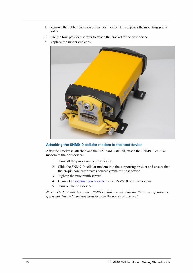
1. Remove the rubber end caps on the host device. This exposes the mounting screw holes.
2. Use the four provided screws to attach the bracket to the host device. 3. Replace the rubber end caps.
Attaching the SNM910 cellular modem to the host device After the bracket is attached and the SIM card installed, attach the SNM910 cellular modem to the host device:
1. Turn off the power on the host device. 2. Slide the SNM910 cellular modem into the supporting bracket and ensure that
the 26-pin connector mates correctly with the host device. 3. Tighten the two thumb screws. 4. Connect an external power cable to the SNM910 cellular modem. 5. Turn on the host device.
Note – The host will detect the SNM910 cellular modem during the power up process. If it is not detected, you may need to cycle the power on the host.

SNM910 Cellular Modem Getting Started Guide 11
Rear view
Front view

12 SNM910 Cellular Modem Getting Started Guide
Host Devices The SNM910 is an add-on GPRS module for the SPS Modular receivers or SNB900 Radio (also known as host devices). The SNM910 cellular modem cannot operate without a host device.
The following host devices are supported:
• SPSx50 (SPS550, SPS750, SPS850)
• SPSx51 (SPS351, SPS551, SPS651, SPS751, SPS851)
• SPS852
• SPSx61 (SPS361, SPS461)
• SNB900

SNM910 Cellular Modem Getting Started Guide 13
External Power Sources of external power include: • AC power • 12 V car or truck battery • Trimble custom external battery pack • Generator power • Solar panel
The cellular modem is powered by an external power source using any one of the following methods:
1. Connect cable 46125-20 to the 7-pin Lemo socket and then connect the crocodile clips to the 12 V vehicle battery.
2. Connect cable 57167, 57168, 77070-00, or 78235-00 to the 26-pin connector and then connect the power jack from the Trimble AC power adapter to the power jack socket on the cable.
3. Connect cable 59044 or 67384 to the 7-pin Lemo socket and then connect the power jack from the Trimble AC power adapter to the power jack socket on the cable.
When connected to the SPS852 modular receiver, and if no external power is applied, the SNM910 cellular modem draws power from the internal battery of the SPS852 receiver.
Part Number
SNM910 connection
Power connection Power Source Other connectors
46125-20 7-pin Lemo 'Croc' clips Power from 12 V vehicle battery
None
59044 7-pin Lemo Cable with DC plug Power from 12 V vehicle battery
Serial
67384 7-pin Lemo Cable with DC plug Power to host devices from AC adapter
Serial to serial for Moving Base applications
57167 26-pin Adapter with DC plug
Power from AC adapter USB(B) socket and Ethernet socket
57168 26-pin Adapter with DC plug
Power from AC adapter Serial and Ethernet socket
60789-00, 77070-00
26-pin Cable with DC plug Power from AC adapter 2 x Serial, Ethernet plug, USB(A) plug, 1PPS (BNC)
65791-00, 78235-00
26-pin Cable with DC plug Power from AC adapter 2 x Serial, Ethernet socket
Connecting the SNM910 cellular modem to a vehicle battery WARNING – Use caution when connecting battery cable's clip leads to a vehicle battery. Do not allow any metal object or jewelry to connect (short) the battery's positive (+) terminal to either the negative (-) terminal or the metal of the vehicle connected to the battery. This could result in high current, arcing, and high temperatures, exposing the user to possible injury.
WARNING – When connecting an external battery, such as a vehicle battery, to an SPS receiver, ensure that you use the Trimble cable with proper over-current protection intended for this purpose, to avoid a safety hazard to the user or damage to the product.

14 SNM910 Cellular Modem Getting Started Guide
Using the SNM910 with SPS Receivers
You can set up a base station in different ways depending on the application, coverage area, degree of permanence versus mobility, and available infrastructure. Before you set up a base station, please see the Setup Guidelines.
Setting up a base station for permanent or semi-permanent installation For construction applications, where machine and site positioning operations using GPS will be carried out over a long time (weeks, months, or years), ensure that you carefully choose the base station location.
A semi-permanent or permanent base station helps to eliminate the types of error that can result from repeated daily setups, and ensures that you always use the GPS antenna at the exact original location. The requirement for a permanent base station setup increases as more receivers that use the base station as a source of corrections, increases the cost of any base station downtime.
On the largest jobsites, and on those that remain operational for the longest time, a permanent or semi-permanent installation is a popular solution. A SPS Modular receiver is typically used as the base station, located in a site office or trailer where it is easy to access (to check or configure), and where it is secure from theft and the weather. The GPS and radio antennas are normally mounted on a permanent structure on the roof of the building, where they are high and clear from obstructions and where the radio antenna can provide the maximum range of operation.
Trimble recommends that you use the Trimble Zephyr Geodetic Model 2 GPS antenna. This antenna has a large ground plane that reduces multipath, providing the best GPS performance at the base location. The antennas are connected to the receiver by high quality RF cables.
The receiver is connected to a permanent power supply (mains or generator power). The internal battery of the receiver is always being charged, and acts as an uninterruptible power supply if there is a power failure. In some cases, the receiver may also be connected by an Ethernet cable to the Internet (either through the SNM910 cellular modem or the SNM920 cellular router), so that it can be monitored and configured from a remote location, and can warn an administrator by email or text message if there is a change to the configuration or status. In these situations, the receiver can transmit corrections to a remote radio or receiver over the Internet, for rebroadcast requirements, without using repeaters.

SNM910 Cellular Modem Getting Started Guide 15
Setting up a base station for daily site use: T-Bar For construction applications where a daily setup and takedown of equipment is required for security reasons, Trimble recommends that you use a T-Bar setup.
The T-Bar consists of a post mounted in concrete (so it cannot move), which has a solid metal T-Bar mounted to it to provide lateral and vertical separation between the GPS antenna and radio antenna. The T piece of the T-Bar has a vertical rod at each end. Each end terminates in a 5/8"×11 thread to which the antennas can be mounted. Trimble recommends that one end is clearly marked GPS and the other end is clearly marked Radio so that at each daily setup, the GPS and radio antennas are mounted at the same location. Switching antennas by mistake introduces a position error in all resulting measurements. You can buy the parts you need to make a T-Bar from any reputable hardware store. Make certain that the T-Bar cannot rotate after construction. Rotation of the T-Bar can introduce a position error into all subsequent measurements.
On the upright post, mount either a bracket (to which the GPS receiver can be mounted), or a well-ventilated lockbox (in which the GPS receiver itself can be secured).
Each day, mount the GPS antenna on the GPS end of the T-Bar and the radio antenna on the Radio end of the T-Bar. Connect the antennas to the receiver using the appropriate cables. The receiver uses its own integrated battery, or an external 12 V battery through the 12 V crocodile clips cable that are provided with the receiver.
Note: If you choose to use AC power, remember that the heat generated by the charging process and the radio transmitter increases the need for good ventilation around the receiver.
Advantages Use of a T-Bar setup ensures that the base station is set up with exactly the same position and height every day. This helps eliminate the errors typically associated with
16 SNM910 Cellular Modem Getting Started Guide
daily tripod setup. For example, wrong antenna height, base not set up over the point, base set up in the wrong location.
Setting up a mobile base station: Tripod and fixed height tripod If you are repeatedly moving between jobsites, or if you are visiting a jobsite for the first time before a T-Bar or similar setup can be established, Trimble recommends that you use either a tripod and tribrach setup, or a fixed height tripod.
The fixed height tripod is quicker and easier to set up over a control point. It allows you to re-establish the antenna height exactly so that the receiver can be set up faster without using the SCS900 software or without needing to enter a revised antenna height in the receiver front panel. Take great care to ensure that the GPS antenna is set up accurately over the control point, and that the GPS antenna height is measured accurately, in the right way (vertical or slope height) to the right location on the antenna (base of antenna or to a specified location on the antenna). When you start the rover receiver, it is extremely important to check in, at one or more known locations, to check for possible position or height errors. Checking in at a known location is good practice and can avoid costly errors caused by a bad setup.
Typically, the tripod and fixed height tripod methods do not give significant height clearance above the ground, and can reduce the range of operation caused by radio limitations.
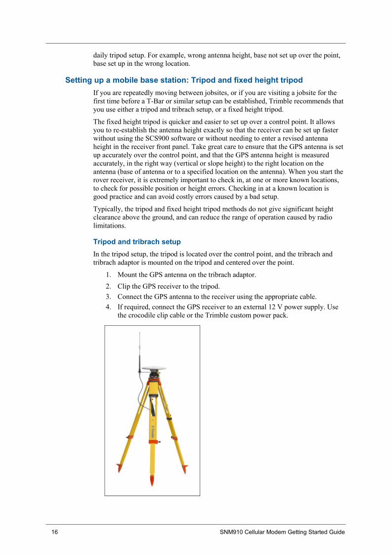
Tripod and tribrach setup In the tripod setup, the tripod is located over the control point, and the tribrach and tribrach adaptor is mounted on the tripod and centered over the point.
1. Mount the GPS antenna on the tribrach adaptor. 2. Clip the GPS receiver to the tripod. 3. Connect the GPS antenna to the receiver using the appropriate cable. 4. If required, connect the GPS receiver to an external 12 V power supply. Use
the crocodile clip cable or the Trimble custom power pack.

SNM910 Cellular Modem Getting Started Guide 17
Fixed height tripod setup A fixed height tripod setup is similar to a tripod setup, but is simplified by the central leg of the tripod, which is placed directly on the control point. If the central leg is leveled accurately, the fixed height tripod is quick and easy to set up, and provides an accurate way to measure the true antenna height.
1. Set up the tripod over the control point. 2. Attach the GPS antenna to the head of the tripod. 3. If using an external high-gain radio antenna, mount the radio antenna to the
radio antenna bracket that is attached to the head of the tripod (beneath the GPS antenna). See the figure below.
4. Hook the receiver to the center leg of the tripod, using the tripod clip.
Adding Internet Base Station Service (IBSS) capability By adding an SNM910 cellular modem to the SPS Modular base station, the Tripod setup can be used to provide corrections through the internal 900 MHz radio and also through the Internet using the IBSS.
• Configuring an IBSS Field Base using the web interface
• Configuring an IBSS Field Base using the receiver

18 SNM910 Cellular Modem Getting Started Guide
SNM910 attached to an SPS Modular base station with mounting bracket
Antenna mounting for best performance If you are using 900 MHz or 850 MHz GSM from your cellular network provider, there should be at least 1 m separation between the SNM910 (with internal cellular antenna) cellular modem and any 900 MHz transmitting antenna. Trimble recommends using an external 900 MHz antenna kit in place of the “rubber duck” antenna fitted to the back of the SPS852 Modular receiver.
CAUTION – Failure to provide the minimum 1 m antenna separation may result in loss of data reception on both the 900 MHz and GSM network, and a reduction in quality or loss of the cellular service.
Configuring an IBSS Field Base using the web interface To configure the IBSS field base in the office, use a computer or laptop running a Windows operating system:
1. Use the mounting bracket to attach the modem to the SPS Modular receiver. 2. Connect cable 57167, 57168, 77070-00, or 78235-00 to the 26-pin connector on the
modem and then connect the power jack from the Trimble AC power adapter to the power jack socket on the cable.
3. Use an ethernet cable to connect the SPS Modular receiver to a network or directly to the device running the Windows® operating system.

SNM910 Cellular Modem Getting Started Guide 19
4. Press on the front panel to find the ethernet IP address of the SPS Modular receiver, open a web browser and then enter the IP address in the Address field.
Note – The default login for the SPS Modular receiver is Admin / password. 5. Select Receiver Configuration / General to set the receiver as a base. 6. Select Receiver Configuration / Reference Station to set the base position and
name.
Note – The Reference Station name is used as the IBSS base station name. 7. Select SNM910 Modem / Configuration to set the GPRS Service provider access. 8. Select Change GPRS Service to select the GPRS access information based on
Country, Provider, and Plan or manually enter the APN, CID, username, and password
9. Save the settings and then press Connect. 10. Monitor the State until the Modem has connected to the Internet. 11. Select I/O Configuration / IBSS/NTRIP Server and then select IBSS Mode. 12. Enter your TCC Organization and Password. 13. Select the required Output format (the default is the CMRx format). 14. Select the Enable check box and then press OK.
Controlling an IBSS Field Base using the receiver Once the IBSS Field Base is configured, it can been turned on and turned off from the front panel of the receiver:
1. From the home screen, press , , and then press or to select either:
• Connect
• Disconnect
• Reset
2. Press to activate the command.
Checking the status of the IBSS using the receiver
From the home screen, press to view the modem status. This screen shows the status of the SNM910 connection:
If the SNM910 status is … It means that …
Wrong PIN You have entered an incorrect CPIN for the SIM. Need PIN You need to enter a CPIN for the SIM. Need PUK You have entered an incorrect CPIN three times; enter the 8-digit
PUK supplied by the service provider. No SIM No SIM has been detected. ISP Connected You are connected to the Internet. ISP in Progress Internet connection is in progress. ISP Failed Start The SNM910 could not connect to the ISP. Bad Base or MP Invalid mount point or base name. Bad Credentials Unknown TCC device ID, or incorrect user name or password.

20 SNM910 Cellular Modem Getting Started Guide
Data Unavailable No response or No GNSS Data from IBSS or NTRIP source. Bad Server URL Failed to connect to IBSS/NTRIP Caster. Check the TCC org or
NTRIP URL. Receiver data IBSS/NTRIP receiving correction data. Sending data IBS Base sending correction data to IBSS.

SNM910 Cellular Modem Getting Started Guide 21
Using the SNM910 with an SNB900 radio
A 900 MHz rebroadcast system transmits correction data from a remote internet base station or NTRIP source to rovers over the 900 MHz radio network. In this case the internet connection is provided by the SNM910 cellular modem.
The main advantage of using a rebroadcast system is to cover a wider area with a single base station without having to use repeaters. Precise RTK accuracies can be achieved at up to 30km from the IBS (Internet Base Station).
IBSS 900 MHz Rebroadcaster setup Trimble recommends that you configure the SNB900 radio as a Rebroadcaster in the office before mobilisation. To do this:
15. Insert the SIM card and attach the bracket (as described earlier). 16. Insert the SNM910 modem into the bracket and tighten the thumbscrews. 17. Connect adapter P/N 57158 to the 26-pin connector on the modem and then
connect the power cable to the adapter. 18. Use an Ethernet cable to connect a laptop running the Windows®
operating system to the adapter and then turn on both the SNM910 modem and the SNB900 radio.
Note: The laptop must not have any existing wireless or wired Ethernet connections.
19. Press to navigate to the Protocol screen and then press to select Easy IP.
20. After the modem has saved and rebooted, press to navigate to the Mode screen and then press to select Rebroadcaster. The modem saves and reboots.
21. Press to navigate to the Ethernet Addr screen and make a note of the IP address (normally 169.254.2.1).
22. Open a browser application (for example, Mozilla Firefox or the Internet Explorer®
internet browser) and then enter the IP address into the address field. The SNB900 web interface appears.
23. Open the SNM910 Modem page and then click Configure to set the APN, CID, user name, and password provided by your Internet Service Provider.
24. Click Apply Settings and then click Reboot to reboot the radio. 25. Open the IBSS/NTRIP Client page, set the Mode to IBSS, enter the TCC Org, TCC
Password, and Base Name and then click Save Changes.
Note: Base Org is required only if the Base belongs to a different TCC Organisation.
26. Open the Configure wireless page, set the Network number and Easy IP name for the 900 MHz radio and then click Apply Settings.
You can now turn off the Rebroadcaster and mobilise it.
In the field, select an appropriate site for the Rebroadcaster. The location should:
• Have good cellular reception (press on the radio to check the SNM910 RSSI).

22 SNM910 Cellular Modem Getting Started Guide
• Provide the required 900 MHz radio coverage for your operations.
Note: You must use an external radio antenna kit for the internal 900 MHz radio. To avoid interference between the 900MHz radio and GPRS transmissions, do not mount the external radio antenna within 1 m (3.3 ft) of the SNM910 modem.
1. Use a tripod or post to mount the Rebroadcaster and external 900 MHz radio antenna.
2. Connect cable P/N 46125-20 to the 7-pin Lemo socket on the modem and then connect the crocodile clips to a 12 V DC power source to provide power for both the modem and the radio.
3. Turn on the radio—the previous configuration is reused. 4. Press twice to view the SNM910 Status screen:
If the SNM910 status is … It means that …
No SIM Detected You have entered an incorrect CPIN for the SIM. SIM Locked You need to enter a CPIN for the SIM. Bad APN or CID You have entered an incorrect CPIN three times; enter the 8-digit
PUK supplied by the service provider. ISP Failed Start The SNM910 could not connect to the ISP. ISP Terminated The ISP connection has been terminated but will try again. Bad Base or MP Invalid mount point or base name. Bad Credentials Unknown TCC device ID, or incorrect user name or password. Data Unavailable No response or No GNSS Data from IBSS or NTRIP source. Bad Server URL Failed to connect to IBSS/NTRIP Caster. Check the TCC org or
NTRIP URL. Lost ISP Lost ISP connection, will re-establish NTRIP/IBSS when
reconnected to ISP. Up and Connected The SNM910 modem is connected to IBSS/NTRIP. Receiving data IBSS/NTRIP receiving correction data. “Data” may be replaced
by the correction type, for example, CMR.

SNM910 Cellular Modem Getting Started Guide 23
Glossary 1PPS Pulse-per-second. Used in hardware timing. A pulse is generated in conjunction
with a time stamp. This defines the instant when the time stamp is applicable.
almanac A file that contains orbit information on all the satellites, clock corrections, and atmospheric delay parameters. The almanac is transmitted by a GPS satellite to a GPS receiver, where it facilitates rapid acquisition of GPS signals when you start collecting data, or when you have lost track of satellites and are trying to regain GPS signals. The orbit information is a subset of the ephemeris/ephemerides data.
AutoBase AutoBase technology uses the position of the receiver to automatically select the correct base station; allowing for one button press operation of a base station. It shortens setup time associated with repeated daily base station setups at the same location on jobsites.
base station Also called reference station. In construction, a base station is a receiver placed at a known point on a jobsite that tracks the same satellites as an RTK rover, and provides a real-time differential correction message stream through radio to the rover, to obtain centimeter level positions on a continuous real-time basis. A base station can also be a part of a virtual reference station network, or a location at which GPS observations are collected over a period of time, for subsequent postprocessing to obtain the most accurate position for the location.
beacon Source of RTCM DGPS corrections transmitted from coastal reference stations in the 283.5 to 325.0 kHz range.
BINEX BINary EXchange format. BINEX is an operational binary format standard for GPS/GLONASS/SBAS research purposes. It is designed to grow and allow encapsulation of all (or most) of the information currently allowed for in a range of other formats.
broadcast server An Internet server that manages authentication and password control for a network of VRS servers, and relays VRS corrections from the VRS server that you select.
carrier A radio wave having at least one characteristic (such as frequency, amplitude, or phase) that can be varied from a known reference value by modulation.
carrier frequency The frequency of the unmodulated fundamental output of a radio transmitter. The GPS L1 carrier frequency is 1575.42 MHz.
carrier phase Is the cumulative phase count of the GPS or GLONASS carrier signal at a given time.
cellular modems A wireless adaptor that connects a laptop computer to a cellular phone system for data transfer. Cellular modems, which contain their own antennas, plug into a PC Card slot or into the USB port of the computer and are available for a variety of wireless data services such as GPRS.
CMR/CMR+ Compact Measurement Record. A real-time message format developed by Trimble for broadcasting corrections to other Trimble receivers. CMR is a more efficient alternative to RTCM.
CMRx A real-time message format developed by Trimble for transmitting more satellite corrections resulting from more satellite signals, more constellations, and more satellites. Its compactness means more repeaters can be used on a site.
covariance A statistical measure of the variance of two random variables that are observed or measured in the same mean time period. This measure is equal to the product of the deviations of corresponding values of the two variables from their

24 SNM910 Cellular Modem Getting Started Guide
respective means.
datum Also called geodetic datum. A mathematical model designed to best fit the geoid, defined by the relationship between an ellipsoid and, a point on the topographic surface, established as the origin of the datum. World geodetic datums are typically defined by the size and shape of an ellipsoid and the relationship between the center of the ellipsoid and the center of the earth. Because the earth is not a perfect ellipsoid, any single datum will provide a better model in some locations than in others. Therefore, various datums have been established to suit particular regions. For example, maps in Europe are often based on the European datum of 1950 (ED-50). Maps in the United States are often based on the North American datum of 1927 (NAD-27) or 1983 (NAD-83). All GPS coordinates are based on the WGS-84 datum surface.
deep discharge Withdrawal of all electrical energy to the end-point voltage before the cell or battery is recharged.
DGPS See real-time differential GPS.
differential correction Differential correction is the process of correcting GPS data collected on a rover with data collected simultaneously at a base station. Because the base station is on a known location, any errors in data collected at the base station can be measured, and the necessary corrections applied to the rover data. Differential correction can be done in real-time, or after the data is collected by postprocessing.
differential GPS See real-time differential GPS.
DOP Dilution of Precision. A measure of the quality of GPS positions, based on the geometry of the satellites used to compute the positions. When satellites are widely spaced relative to each other, the DOP value is lower, and position accuracy is greater. When satellites are close together in the sky, the DOP is higher and GPS positions may contain a greater level of error. PDOP (Position DOP) indicates the three-dimensional geometry of the satellites. Other DOP values include HDOP (Horizontal DOP) and VDOP (Vertical DOP), which indicate the accuracy of horizontal measurements (latitude and longitude) and vertical measurements respectively. PDOP is related to HDOP and VDOP as follows: PDOP² = HDOP² + VDOP².
dual-frequency GPS A type of receiver that uses both L1 and L2 signals from GPS satellites. A dual-frequency receiver can compute more precise position fixes over longer distances and under more adverse conditions because it compensates for ionospheric delays.
EGNOS European Geostationary Navigation Overlay Service. A Satellite-Based Augmentation System (SBAS) that provides a free-to-air differential correction service for GPS. EGNOS is the European equivalent of WAAS, which is available in the United States.
elevation mask The angle below which the receiver will not track satellites. Normally set to 10 degrees to avoid interference problems caused by buildings and trees, atmospheric issues, and multipath errors.
ellipsoid An ellipsoid is the three-dimensional shape that is used as the basis for mathematically modeling the earth’s surface. The ellipsoid is defined by the lengths of the minor and major axes. The earth’s minor axis is the polar axis and the major axis is the equatorial axis.
EHT Height above ellipsoid.
ephemeris/ephemerides A list of predicted (accurate) positions or locations of satellites as a function of time. A set of numerical parameters that can be used to determine a satellite’s

SNM910 Cellular Modem Getting Started Guide 25
position. Available as broadcast ephemeris or as postprocessed precise ephemeris.
epoch The measurement interval of a GPS receiver. The epoch varies according to the measurement type: for real-time measurement it is set at one second; for postprocessed measurement it can be set to a rate of between one second and one minute. For example, if data is measured every 15 seconds, loading data using 30-second epochs means loading every alternate measurement.
feature A feature is a physical object or event that has a location in the real world, which you want to collect position and/or descriptive information (attributes) about. Features can be classified as surface or non-surface features, and again as points, lines/breaklines, or boundaries/areas.
firmware The program inside the receiver that controls receiver operations and hardware.
Galileo Galileo is a GNSS system built by the European Union and the European Space Agency. It is complimentary to PPS and GLONASS.
GHT Height above geoid.
GIOVE Galileo In-Orbit Validation Element. The name of each satellite for the European Space Agency to test the Galileo positioning system.
GLONASS Global Orbiting Navigation Satellite System. GLONASS is a Soviet space-based navigation system comparable to the American GPS system. The operational system consists of 21 operational and 3 non-operational satellites in 3 orbit planes.
GNSS Global Navigation Satellite System.
GSOF General Serial Output Format. A Trimble proprietary message format.
HDOP Horizontal Dilution of Precision. HDOP is a DOP value that indicates the accuracy of horizontal measurements. Other DOP values include VDOP (vertical DOP) and PDOP (Position DOP). Using a maximum HDOP is ideal for situations where vertical precision is not particularly important, and your position yield would be decreased by the vertical component of the PDOP (for example, if you are collecting data under canopy).
IBSS Internet Base Station Service. This Trimble service makes the setup of an Internet-capable SPS receiver as simple as possible. The base station can be connected to the Internet (cable or wirelessly). To access the distribution server, the user must enter a password into the receiver. To use the server, the user must have a Trimble Connected Community site license.
L1 The primary L-band carrier used by GPS and GLONASS satellites to transmit satellite data.
L2 The secondary L-band carrier used by GPS and GLONASS satellites to transmit satellite data.
L2C A modernized code that allows significantly better ability to track the L2 frequency.
L5 The third L-band carrier used by GPS satellites to transmit satellite data. L5 will provide a higher power level than the other carriers. As a result, acquiring and tracking weak signals will be easier.
Location RTK Some applications such as vehicular-mounted site supervisor systems do not require Precision RTK accuracy. Location RTK is a mode in which, once initialized, the receiver will operate either in 10 cm horizontal and 10 cm vertical accuracy, or in 10 cm horizontal and and 2 cm vertical accuracy.
Mountpoint Every single NTripSource needs a unique mountpoint on an NTripCaster.

26 SNM910 Cellular Modem Getting Started Guide
Before transmitting GNSS data to the NTripCaster, the NTripServer sends an assignment of the mountpoint.
Moving Base Moving Base is an RTK positioning technique in which both reference and rover receivers are mobile. Corrections are sent from a “base” receiver to a “rover” receiver and the resultant baseline (vector) has centimeter-level accuracy.
MSAS MTSAT Satellite-Based Augmentation System. A Satellite-Based Augmentation System (SBAS) that provides a free-to-air differential correction service for GPS. MSAS is the Japanese equivalent of WAAS, which is available in the United States.
multipath Interference, similar to ghosts on an analog television screen, that occurs when GPS signals arrive at an antenna having traversed different paths. The signal traversing the longer path yields a larger pseudorange estimate and increases the error. Multiple paths can arise from reflections off the ground or off structures near the antenna.
NMEA National Marine Electronics Association. NMEA 0183 defines the standard for interfacing marine electronic navigational devices. This standard defines a number of 'strings' referred to as NMEA strings that contain navigational details such as positions. Most Trimble GPS receivers can output positions as NMEA strings.
NTrip Protocol Networked Transport of RTCM via Internet Protocol (NTrip) is an application-level protocol that supports streaming Global Navigation Satellite System (GNSS) data over the Internet. NTrip is a generic, stateless protocol based on the Hypertext Transfer Protocol (HTTP). The HTTP objects are extended to GNSS data streams.
NTripCaster The NTripCaster is basically an HTTP server supporting a subset of HTTP request/response messages and adjusted to low-bandwidth streaming data. The NTripCaster accepts request messages on a single port from either the NTripServer or the NTripClient. Depending on these messages, the NTripCaster decides whether there is streaming data to receive or to send. Trimble NTripCaster integrates the NTripServer and the NTripCaster. This port is used only to accept requests from NTripClients.
NTripClient An NTripClient will be accepted by and receive data from an NTripCaster, if the NTripClient sends the correct request message (TCP/UDP connection to the specified NTripCaster IP and listening port).
NTripServer The NTripServer is used to transfer GNSS data of an NTripSource to the NTripCaster. An NTripServer in its simplest setup is a computer program running on a PC that sends correction data of an NTripSource (for example, as received through the serial communication port from a GNSS receiver) to the NTripCaster. The NTripServer - NTripCaster communication extends HTTP by additional message formats and status codes.
NTripSource The NTripSources provide continuous GNSS data (for example, RTCM-104 corrections) as streaming data. A single source represents GNSS data referring to a specific location. Source description parameters are compiled in the source-table.
OmniSTAR The OmniSTAR HP/XP service allows the use of new generation dual-frequency receivers with the OmniSTAR service. The HP/XP service does not rely on local reference stations for its signal, but utilizes a global satellite monitoring network. Additionally, while most current dual-frequency GPS systems are accurate to within a meter or so, OmniSTAR with XP is accurate in 3D to better than 30 cm.
PDOP Position Dilution of Precision. PDOP is a DOP value that indicates the accuracy

SNM910 Cellular Modem Getting Started Guide 27
of three-dimensional measurements. Other DOP values include VDOP (vertical DOP) and HDOP (Horizontal Dilution of Precision). Using a maximum PDOP value is ideal for situations where both vertical and horizontal precision are important.
POE Power Over Ethernet. Provides DC power to the SPS Modular receiver using an Ethernet cable.
postprocessing Postprocessing is the processing of satellite data after it is collected, in order to eliminate error. This involves using computer software to compare data from the rover with data collected at the base station.
real-time differential GPS
Also known as real-time differential correction or DGPS. Real-time differential GPS is the process of correcting GPS data as you collect it. Corrections are calculated at a base station and then sent to the receiver through a radio link. As the rover receives the position it applies the corrections to give you a very accurate position in the field. Most real-time differential correction methods apply corrections to code phase positions. While DGPS is a generic term, its common interpretation is that it entails the use of single-frequency code phase data sent from a GPS base station to a rover GPS receiver to provide sub-meter position accuracy. The rover receiver can be at a long range (greater than 100 kms (62 miles)) from the base station.
rover A rover is any mobile GPS receiver that is used to collect or update data in the field, typically at an unknown location.
Roving mode Roving mode applies to the use of a rover receiver to collect data, stakeout, or control earthmoving machinery in real time using RTK techniques.
RTCM Radio Technical Commission for Maritime Services. A commission established to define a differential data link for the real-time differential correction of roving GPS receivers. There are three versions of RTCM correction messages. All Trimble GPS receivers use Version 2 protocol for single-frequency DGPS type corrections. Carrier phase corrections are available on Version 2, or on the newer Version 3 RTCM protocol, which is available on certain Trimble dual-frequency receivers. The Version 3 RTCM protocol is more compact but is not as widely supported as Version 2.
RTK real-time kinematic. A real-time differential GPS method that uses carrier phase measurements for greater accuracy.
SBAS Satellite-Based Augmentation System. SBAS is based on differential GPS, but applies to wide area (WAAS/EGNOS/MSAS) networks of reference stations. Corrections and additional information are broadcast using geostationary satellites.
signal-to-noise ratio SNR. The signal strength of a satellite is a measure of the information content of the signal, relative to the signal’s noise. The typical SNR of a satellite at 30° elevation is between 47 and 50 dBHz.
skyplot The satellite skyplot confirms reception of a differentially corrected GPS signal and displays the number of satellites tracked by the GPS receiver, as well as their relative positions.
SNR See signal-to-noise ratio.
Source-table The NTripCaster maintains a source-table containing information on available NTripSources, networks of NTripSources, and NTripCasters, to be sent to an NTripClient on request. Source-table records are dedicated to one of the following: • data STReams (record type STR) • CASters (record type CAS)

28 SNM910 Cellular Modem Getting Started Guide
• NETworks of data streams (record type NET) All NTripClients must be able to decode record type STR. Decoding types CAS and NET is an optional feature. All data fields in the source-table records are separated using the semicolon character.
triple frequency GPS A type of receiver that uses three carrier phase measurements (L1, L2, and L5).
UTC Universal Time Coordinated. A time standard based on local solar mean time at the Greenwich meridian.
VRS Virtual Reference Station. A VRS system consists of GPS hardware, software, and communication links. It uses data from a network of base stations to provide corrections to each rover that are more accurate than corrections from a single base station. To start using VRS corrections, the rover sends its position to the VRS server. The VRS server uses the base station data to model systematic errors (such as ionospheric noise) at the rover position. It then sends RTCM correction messages back to the rover.
WAAS Wide Area Augmentation System. WAAS was established by the Federal Aviation Administration (FAA) for flight and approach navigation for civil aviation. WAAS improves the accuracy and availability of the basic GPS signals over its coverage area, which includes the continental United States and outlying parts of Canada and Mexico. The WAAS system provides correction data for visible satellites. Corrections are computed from ground station observations and then uploaded to two geostationary satellites. This data is then broadcast on the L1 frequency, and is tracked using a channel on the GPS receiver, exactly like a GPS satellite. Use WAAS when other correction sources are unavailable, to obtain greater accuracy than autonomous positions. For more information on WAAS, refer to the FAA website at http://gps.faa.gov. The EGNOS service is the European equivalent and MSAS is the Japanese equivalent of WAAS.
WGS-84 World Geodetic System 1984. Since January 1987, WGS-84 has superseded WGS-72 as the datum used by GPS. The WGS-84 datum is based on the ellipsoid of the same name.