getting started sinamics s120 - siemens · using documentation online ... sinamics s120 getting...
TRANSCRIPT

SINAMICS
Getting Started · 01/2012
SINAMICS S120
s


SINAMICS
S120 Getting Started
Getting Started
Valid from firmware version 4.5
01/2012 6SL3097-4AG00-0BP1
Preface
SINAMICS S120 drive system
1
Requirements 2
Creating a drive project 3
Configuring your drive project
4
Commissioning a drive 5
Legal information Warning notice system
This manual contains notices you have to observe in order to ensure your personal safety, as well as to prevent damage to property. The notices referring to your personal safety are highlighted in the manual by a safety alert symbol, notices referring only to property damage have no safety alert symbol. These notices shown below are graded according to the degree of danger.
DANGER indicates that death or severe personal injury will result if proper precautions are not taken.
WARNING indicates that death or severe personal injury may result if proper precautions are not taken.
CAUTION with a safety alert symbol, indicates that minor personal injury can result if proper precautions are not taken.
CAUTION without a safety alert symbol, indicates that property damage can result if proper precautions are not taken.
NOTICE indicates that an unintended result or situation can occur if the relevant information is not taken into account.
If more than one degree of danger is present, the warning notice representing the highest degree of danger will be used. A notice warning of injury to persons with a safety alert symbol may also include a warning relating to property damage.
Qualified Personnel The product/system described in this documentation may be operated only by personnel qualified for the specific task in accordance with the relevant documentation, in particular its warning notices and safety instructions. Qualified personnel are those who, based on their training and experience, are capable of identifying risks and avoiding potential hazards when working with these products/systems.
Proper use of Siemens products Note the following:
WARNING Siemens products may only be used for the applications described in the catalog and in the relevant technical documentation. If products and components from other manufacturers are used, these must be recommended or approved by Siemens. Proper transport, storage, installation, assembly, commissioning, operation and maintenance are required to ensure that the products operate safely and without any problems. The permissible ambient conditions must be complied with. The information in the relevant documentation must be observed.
Trademarks All names identified by ® are registered trademarks of Siemens AG. The remaining trademarks in this publication may be trademarks whose use by third parties for their own purposes could violate the rights of the owner.
Disclaimer of Liability We have reviewed the contents of this publication to ensure consistency with the hardware and software described. Since variance cannot be precluded entirely, we cannot guarantee full consistency. However, the information in this publication is reviewed regularly and any necessary corrections are included in subsequent editions.
Siemens AG Industry Sector Postfach 48 48 90026 NÜRNBERG GERMANY
Order number: 6SL3097-4AG00-0BP1 Ⓟ 06/2012 Technical data subject to change
Copyright © Siemens AG 2012. All rights reserved

Getting Started Getting Started, 01/2012, 6SL3097-4AG00-0BP1 3
Preface
SINAMICS documentation The SINAMICS documentation is organized in the following categories:
● General documentation/catalogs
● User documentation
● Manufacturer/service documentation
More information The following link provides information on the topics:
● Ordering documentation/overview of documentation
● Additional links to download documents
● Using documentation online (find and browse through manuals/information) http://www.siemens.com/motioncontrol/docu
Please send any questions about the technical documentation (e.g. suggestions for improvement, corrections) to the following e-mail address: [email protected]
My Documentation Manager Under the following link there is information on how to create your own individual documentation based on Siemens' content, and adapt it for your own machine documentation: http://www.siemens.com/mdm
Training Under the following link there is information on SITRAIN - training from Siemens for products, systems and automation engineering solutions: http://www.siemens.com/sitrain
FAQs You can find Frequently Asked Questions in the Service&Support pages under Product Support: http://support.automation.siemens.com
SINAMICS You can find information on SINAMICS under: http://www.siemens.com/sinamics

Preface
Getting Started 4 Getting Started, 01/2012, 6SL3097-4AG00-0BP1
Usage phases and their documents/tools (as an example)
Table 1 Usage phases and the available documents/tools
Usage phase Document/tool Orientation SINAMICS S Sales Documentation Planning/configuration SIZER engineering tool
Configuration Manuals, Motors
Deciding/ordering SINAMICS S120 catalogs SIMOTION, SINAMICS S120 and Motors for Production
Machines (Catalog PM 21) SINAMICS and motors for single-axis drives (Catalog D 31) SINUMERIK & SINAMICS
Equipment for Machine Tools (Catalog NC 61) SINUMERIK 840D sl Type 1B
Equipment for Machine Tools (Catalog NC 62)
Installation/assembly SINAMICS S120 Equipment Manual for Control Units and Additional System Components
SINAMICS S120 Equipment Manual for Booksize Power Units
SINAMICS S120 Equipment Manual for Chassis Power Units
SINAMICS S120 Equipment Manual for AC Drives SINAMICS S120M Equipment Manual Distributed Drive
Technology
Commissioning STARTER commissioning tool SINAMICS S120 Getting Started SINAMICS S120 Commissioning Manual SINAMICS S120 CANopen Commissioning Manual SINAMICS S120 Function Manual SINAMICS S120/S150 List Manual
Usage/operation SINAMICS S120 Commissioning Manual SINAMICS S120/S150 List Manual
Maintenance/servicing SINAMICS S120 Commissioning Manual SINAMICS S120/S150 List Manual
References SINAMICS S120/S150 List Manual
Target group This documentation is intended for machine manufacturers, commissioning engineers, and service personnel who use the SINAMICS drive system.

Preface
Getting Started Getting Started, 01/2012, 6SL3097-4AG00-0BP1 5
Benefits This Manual describes all the information, procedures and operational instructions required for commissioning and servicing SINAMICS S120.
Standard scope The scope of the functionality described in this document may differ from the scope of the functionality of the drive system that is actually supplied.
● It may be possible for other functions not described in this documentation to be executed in the drive system. However, no claim can be made regarding the availability of these functions when the equipment is first supplied or in the event of servicing.
● Functions that are not available in a particular product version of the drive system may be described in the documentation. The functionality of the supplied drive system should only be taken from the ordering documentation.
● Extensions or changes made by the machine manufacturer must be documented by the machine manufacturer.
For reasons of clarity, this documentation does not contain all of the detailed information on all of the product types. This documentation cannot take into consideration every conceivable type of installation, operation and service/maintenance.
Technical Support Country-specific telephone numbers for technical support are provided in the Internet under Contact:
http://www.siemens.com/automation/service&support
EC Declaration of Conformity The EC Declaration of Conformity for the EMC Directive can be found on the Internet at:
http://support.automation.siemens.com
There – as a search term – enter the number 15257461 or contact your local Siemens office.
Purpose of this document This documentation is aimed at beginners who want to find out more about the SINAMICS S120 drive system. The document offers a brief guide to commissioning a sample project with a simple SINAMICS S120 drive train. By following the instructions in this document, a beginner will need only a few minutes to engineer and configure the sample project and start up the motor.

Preface
Getting Started 6 Getting Started, 01/2012, 6SL3097-4AG00-0BP1
ESD Notes
CAUTION Electrostatic sensitive devices (ESD) are single components, integrated circuits or devices that can be damaged by electrostatic fields or electrostatic discharges.
Regulations for the ESD handling:
During the handling of electronic components, pay attention to the grounding of the person, workplace and packaging!
Electronic components may be touched by persons only when these persons are grounded using an ESD bracelet, or these persons in ESD areas with a conducting floor wear ESD shoes or ESD grounding
straps.
Electronic components should be touched only when this is unavoidable. The touching is permitted only on the front panel or on the circuit board edge.
Electronic components must not be brought into contact with plastics or clothing made of artificial fibers.
Electronic components may only be placed on conducting surfaces (table with ESD coating, conducting ESD foamed material, ESD packing bag, ESD transport container).
Electronic components may not be placed near display units, monitors or televisions (minimum distance from the screen > 10 cm).
Measurements must only be taken on boards when the measuring instrument is grounded (via protective conductors, for example) or the measuring probe is briefly discharged before measurements are taken with an isolated measuring device (for example, touching a bare metal housing).

Preface
Getting Started Getting Started, 01/2012, 6SL3097-4AG00-0BP1 7
Safety notices
DANGER Commissioning is absolutely prohibited until it has been completely ensured that the
machine, in which the components described here are to be installed, is in full compliance with the provisions of the EC Machinery Directive.
SINAMICS devices and AC motors must only be commissioned by suitably qualified personnel.
The personnel must take into account the information provided in the technical customer documentation for the product, and be familiar with and follow the specified danger and warning notices.
When electrical equipment and motors are operated, the electrical circuits automatically conduct a dangerous voltage.
When the machine or system is operated, hazardous axis movements can occur. All of the work carried-out on the electrical machine or system must be carried-out with it
in a no-voltage condition. SINAMICS devices with three-phase motors must only be connected to the power
supply via an AC-DC residual-current-operated device with selective switching once it has been verified that the SINAMICS device is compatible with the residual-current-operated device in accordance with IEC 61800-5-1, Section 5.2.11.2.
WARNING The successful and safe operation of this equipment and motors is dependent on
correct transport, proper storage, installation and mounting as well as careful operator control, service and maintenance.
For special versions of the drive units and motors, information and data in the Catalogs and quotations additionally apply.
In addition to the danger and warning information provided in the technical customer documentation, the applicable national, local, and plant-specific regulations and requirements must be taken into account.
Only protective extra-low voltages (PELV, DVC-A) that comply with EN 60204-1:2006 may be connected to the connections and terminals between 0 V and 48 V.

Preface
Getting Started 8 Getting Started, 01/2012, 6SL3097-4AG00-0BP1
CAUTION The motors can have surface temperatures of over +80°C. This is the reason that temperature-sensitive components, e.g. cables or electronic
components may neither be in contact nor be attached to the motor. When attaching the connecting cables, you must ensure that:
– they are not damaged – they are not under tension – they cannot come into contact with any rotating parts.
CAUTION As part of routine tests, SINAMICS devices are subject to a voltage test in accordance
with IEC 61800-5-1. Before the voltage test is performed on the electrical equipment of industrial machines to EN 60204-1:2006, Section 18.4, all connectors of SINAMICS equipment must be disconnected/unplugged to prevent the equipment from being damaged.
Motors should be connected-up according to the circuit diagram provided. otherwise they can be destroyed.
Note
When operated in dry areas, SINAMICS devices with three-phase motors conform to the Low-Voltage Directive 2006/95/EC.

Getting Started Getting Started, 01/2012, 6SL3097-4AG00-0BP1 9
Table of contents
Preface ...................................................................................................................................................... 3
1 SINAMICS S120 drive system................................................................................................................. 11
1.1 Overview ......................................................................................................................................11
1.2 SINAMICS S120 system overview...............................................................................................12
2 Requirements .......................................................................................................................................... 15
2.1 Hardware and software components ...........................................................................................15
2.2 Wiring the components ................................................................................................................16
3 Creating a drive project............................................................................................................................ 17
3.1 Setting the communication interfaces..........................................................................................18 3.1.1 Setting up the Ethernet interface .................................................................................................18 3.1.2 Assigning the Ethernet interface in STARTER ............................................................................19
3.2 Creating a new drive project ........................................................................................................20
4 Configuring your drive project .................................................................................................................. 25
4.1 Restoring the factory settings ......................................................................................................25
4.2 Configuring the drive unit .............................................................................................................27
4.3 Configuring the Motor Module......................................................................................................28
4.4 Special features of the SITRAIN training case ............................................................................28
5 Commissioning a drive ............................................................................................................................ 31

Table of contents
Getting Started 10 Getting Started, 01/2012, 6SL3097-4AG00-0BP1

Getting Started Getting Started, 01/2012, 6SL3097-4AG00-0BP1 11
SINAMICS S120 drive system 11.1 Overview
This manual provides instructions on how to commission a simple SINAMICS S120 drive train based on a project example. By way of introduction, this chapter of the manual gives you a brief overview of the SINAMICS S120 drive system.
It describes the following steps required to create a sample project:
Step Action 1 Definition of requirements 2 Establishing communication between the programming device and Control Unit 3 Creation of the sample project with the help of a Wizard 4 Automatic configuration of the sample project 5 Operation of the PG/PC control panel for driving the motor

SINAMICS S120 drive system 1.2 SINAMICS S120 system overview
Getting Started 12 Getting Started, 01/2012, 6SL3097-4AG00-0BP1
1.2 SINAMICS S120 system overview The SINAMICS S120 drive system consists of a variety of different modules. It is constructed of infeeds, filters, motor power units, modules for additional functions, Control Units plus standard and special versions of rotating and linear motors.

SINAMICS S120 drive system 1.2 SINAMICS S120 system overview
Getting Started Getting Started, 01/2012, 6SL3097-4AG00-0BP1 13

SINAMICS S120 drive system 1.2 SINAMICS S120 system overview
Getting Started 14 Getting Started, 01/2012, 6SL3097-4AG00-0BP1

Getting Started Getting Started, 01/2012, 6SL3097-4AG00-0BP1 15
Requirements 22.1 Hardware and software components
● A CU320-2 DP from firmware version 4.5 with integrated Ethernet interface
● A Line Module (infeed module)
● A line filter
● A Motor Module
● A motor with built-on encoder evaluation unit with DRIVE-CLiQ interface (SMI motor)
● A standard PC with Windows XP as programming device (PG/PC), with pre-installed STARTER commissioning tool (firmware version 4.3 or higher)
● Installed motor, power, and control cables
● DRIVE-CLiQ cables
● An Ethernet interface in the PG/PC (in our PG/PC, for the example, a CP 5611 from Belkin is installed)
● Ethernet connection between the PG/PC and the Control Unit

Requirements 2.2 Wiring the components
Getting Started 16 Getting Started, 01/2012, 6SL3097-4AG00-0BP1
2.2 Wiring the components The assembly and wiring of components according to the project example shown below must always be undertaken by qualified specialists. For the purpose of commissioning this project example, it is not permissible to connect other components or drive loads to the motor.
Figure 2-1 Wiring principle

Getting Started Getting Started, 01/2012, 6SL3097-4AG00-0BP1 17
Creating a drive project 3
This chapter shows how you can generate a new drive project using the STARTER commissioning tool. You then transfer the project example via a communication interface to the Control Unit of the drive.
For data exchange between the programming device (PG/PC) and the Control Unit (CU), you can select between PROFIBUS, PROFINET or Ethernet. For our example, we select the commissioning interface for Ethernet, which is currently integrated in every SINAMICS S120 device. For the other interfaces, commissioning is carried out in a similar fashion.
The programming device and the drive are switched on and connected to each other via a data line.

Creating a drive project 3.1 Setting the communication interfaces
Getting Started 18 Getting Started, 01/2012, 6SL3097-4AG00-0BP1
3.1 Setting the communication interfaces
3.1.1 Setting up the Ethernet interface
Communication interface of the programming device ● In the programming device (PG/PC) under Windows ("Settings > Control Panel > Network
connections"), set the IP address for the data link to the Control Unit:
The factory-set IP address of the Ethernet interface of the Control Unit is 169.254.11.22, the subnet mask is 255.255.0.0.
● For this reason, set the IP address of the access interface of the PG/PC to the Control Unit to 169.254.11.1 and the subnet mask to 255.255.0.0. Click "OK" and close the Windows-specific window of the network connections.
Figure 3-1 IP address of PG/PC
Double-click on the symbol to launch the STARTER commissioning tool:
Figure 3-2 STARTER symbol
The main window of the STARTER application is displayed.

Creating a drive project 3.1 Setting the communication interfaces
Getting Started Getting Started, 01/2012, 6SL3097-4AG00-0BP1 19
3.1.2 Assigning the Ethernet interface in STARTER
Assigning the communication interface ● In STARTER, click on the menu command "Tools > Set PG/PC interface...".
● The "Set PG/PC interface" window opens:
Figure 3-3 Creating an access point
● Click in the list box "Interface parameter assignment used:" on the required entry. If the required adapter is not included in the list, you must add the appropriate entry. To do so, click on "Select...".

Creating a drive project 3.2 Creating a new drive project
Getting Started 20 Getting Started, 01/2012, 6SL3097-4AG00-0BP1
● The already installed interfaces are located in the window "Install/uninstall interfaces". If the required interface is not present, you must install it yourself. The entry then appears on the left-hand side of the window. Select the desired interface on the left-hand side, and then click on "Install-- > ". The interface then changes to the right-hand side.
Figure 3-4 Selecting the interface
● Select the required interface and close the window.
Note
The interface in our example has the designation TCP/IP -> Belkin F5D 5055 Gigabit USB 2.0 Network Adapter Any Ethernet interface of the PG/PC can be used.
3.2 Creating a new drive project The project wizard will guide you through all the steps necessary to create and set up a new drive project.
Sequence ● Click on the menu command "Project > New with Wizard".
The start window of the project wizard is opened.
● Click on button "Find drive units online...". The project wizard continues to step 1 "Create new project" window.

Creating a drive project 3.2 Creating a new drive project
Getting Started Getting Started, 01/2012, 6SL3097-4AG00-0BP1 21
● Enter a name for your project, e.g. project example, in the entry field.
● Click on "Continue >".
The project wizard continues to step 2 "PG/PC - Set interface" window.

Creating a drive project 3.2 Creating a new drive project
Getting Started 22 Getting Started, 01/2012, 6SL3097-4AG00-0BP1
● In this window, you can check the settings of the communication interface made in the previous chapter, i.e. you do not have to change anything in this window. Click on "Continue >". The project wizard continues to step 3 to search for drive units. The drive units found are displayed in "Preview".
● Click on "Continue >".
The project wizard continues to step 4 to display a summary of your project settings.

Creating a drive project 3.2 Creating a new drive project
Getting Started Getting Started, 01/2012, 6SL3097-4AG00-0BP1 23
● Click on button "Complete".
The project wizard closes the window.
● The project navigator opens, and under the project example, lists the drive unit found - "S120_CU320-2_DP".

Creating a drive project 3.2 Creating a new drive project
Getting Started 24 Getting Started, 01/2012, 6SL3097-4AG00-0BP1

Getting Started Getting Started, 01/2012, 6SL3097-4AG00-0BP1 25
Configuring your drive project 44.1 Restoring the factory settings
In order to restore the drive to a defined state, before commissioning, reset the drive parameters into the "factory setting" state.
Sequence ● Select the menu command "Project > Connect to selected target devices".
The window "Target Device Selection" opens and lists the configured drive units.
● Check whether the access point is set to "DEVICE", as was selected previously.
● Activate the check box " S120_CU320_2_DP " and click on "OK".
● Click on the "OK" button.
● The PG/PC establishes the link to the Control Unit. It then performs an "Online/offline comparison". The result is displayed in the following dialog "Online/offline comparison".
● Click on the "Close" button in the results window.

Configuring your drive project 4.1 Restoring the factory settings
Getting Started 26 Getting Started, 01/2012, 6SL3097-4AG00-0BP1
● Select drive object S120_CU320_2_DP with the right-hand mouse button and select "Target device > Restore factory settings" in the shortcut menu.
● Confirm the query with "OK".
The PG/PC sets the drive parameters to their factory settings.
● The new status is automatically transferred to the Control Unit memory card using the function "Copy RAM to ROM".
The factory settings have now been restored: the drive is in a defined basic state.

Configuring your drive project 4.2 Configuring the drive unit
Getting Started Getting Started, 01/2012, 6SL3097-4AG00-0BP1 27
4.2 Configuring the drive unit In this chapter, the S120_CU320_2_DP drive unit is configured for operation in the online mode.
Sequence ● In the project navigator, click on the "+" symbol before the entry "S120_CU320_2_DP".
The list of objects for this drive opens and looks like this:
● Double-click on option "Automatic configuration" in the project navigator.
The following window opens:
● Start the automatic configuration of the drive unit by clicking on the "Configure" button.
The programming device (PG/PC) searches the DRIVE-CLiQ bus for connected objects. In the project example, the PG/PC finds a drive.

Configuring your drive project 4.3 Configuring the Motor Module
Getting Started 28 Getting Started, 01/2012, 6SL3097-4AG00-0BP1
● Select the entry "Servo" from the list "Default setting for all components".
The drive in the project example is therefore used as servo control.
● Click on button "Create".
The automatic configuration process commences. When the process has been completed, a window with the message "Automatic configuration is complete" opens.
● Click on "Stay ONLINE".
4.3 Configuring the Motor Module The Control Unit has detected the connected Motor Module and the SMI motor during the automatic configuration process. The device data have been transferred to the Control Unit. The Control Unit has automatically entered the correct device data into the parameters required to operate the components.
The sample project is now ready to commission.
4.4 Special features of the SITRAIN training case If you use the usual training case for SITRAIN, the following special issues must be considered:
Motors In this example, we only commission the DRIVE-CLiQ motor. The second motor is ignored.

Configuring your drive project 4.4 Special features of the SITRAIN training case
Getting Started Getting Started, 01/2012, 6SL3097-4AG00-0BP1 29
Infeed operating message So that you can commission the drive, you will need to define the signal source for the "Operating message of the infeed". In this example, we permanently set this signal to "1".
● From the shortcut menu of the drive, select the "Expert list" command.
● Scroll to parameter p0864.
● There, click on "0".
● Click on row "1" and then click on "OK".
Configuring your drive project 4.4 Special features of the SITRAIN training case
Getting Started 30 Getting Started, 01/2012, 6SL3097-4AG00-0BP1
Device supply voltage You must reduce the device supply voltage so that you can commission the drive.
● From the shortcut menu of the drive, select the "Expert list" command.
● Scroll to parameter p0210 (device supply voltage).
● In the "Online value SERVO_02", overwrite the value "600" with "300".
Getting Started Getting Started, 01/2012, 6SL3097-4AG00-0BP1 31
Commissioning a drive 5
Control panel functions The control panel allows you to perform basic tasks for operating, monitoring, and testing the drive. For operation of the drive, the keys "START", "STOP" and "TIP" and various diagnostic functions are available.
References You can find more information about these functions in the SINAMICS S120 Function Manual.
ON/OFF enable For this example only, assign the ON/OFF signal a permanent value of "1" (p0840 = 1).

Commissioning a drive
Getting Started 32 Getting Started, 01/2012, 6SL3097-4AG00-0BP1
Operation with the virtual control panel ● In the project navigator, double-click on the entry
"S120_CU320_2_DP > Drives > <Drive> > Commissioning > Control panel":
The control panel window is displayed.
● Click on button "Assume control priority!".

Commissioning a drive
Getting Started Getting Started, 01/2012, 6SL3097-4AG00-0BP1 33
The "Assume control priority" window opens in addition.
● Click on button "Safety notes".
The "Safety notes" window opens.
● Read the safety notes and then close the window.
● In the "Assume control priority" window, click on button "Accept". The window is closed and the control panel is activated.
● Activate the check box "Enable signals".
Buttons "I" and "0" become available for selection.
Commissioning a drive
Getting Started 34 Getting Started, 01/2012, 6SL3097-4AG00-0BP1
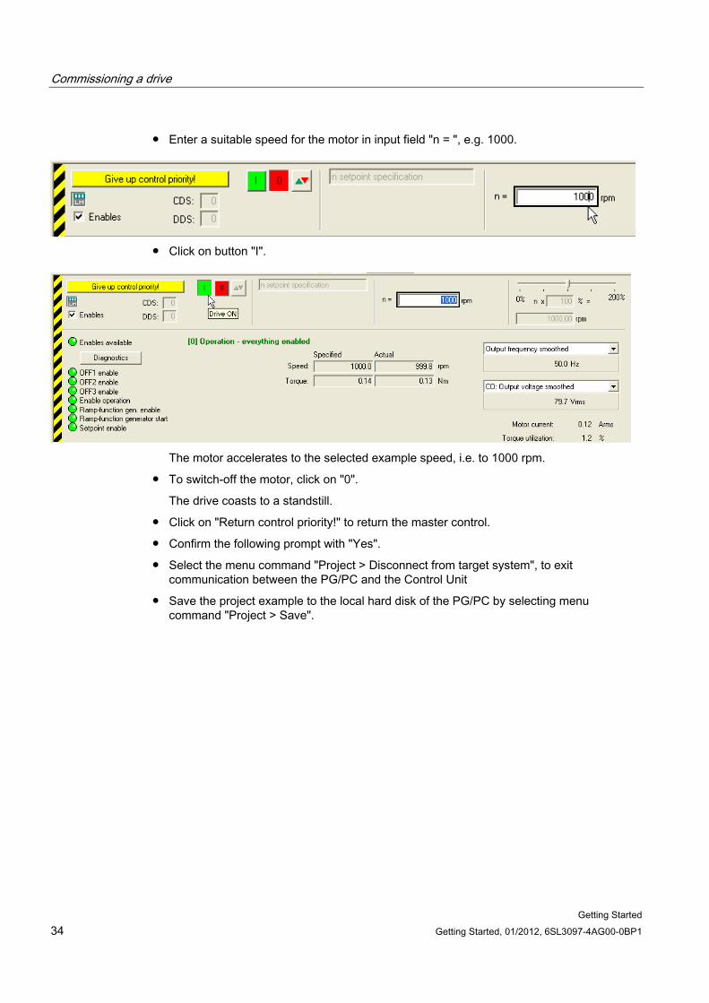
● Enter a suitable speed for the motor in input field "n = ", e.g. 1000.
● Click on button "I".
The motor accelerates to the selected example speed, i.e. to 1000 rpm.
● To switch-off the motor, click on "0".
The drive coasts to a standstill.
● Click on "Return control priority!" to return the master control.
● Confirm the following prompt with "Yes".
● Select the menu command "Project > Disconnect from target system", to exit communication between the PG/PC and the Control Unit
● Save the project example to the local hard disk of the PG/PC by selecting menu command "Project > Save".


www.siemens.com/motioncontrol
Subject to change without prior notice© Siemens AG 2012
Siemens AGIndustry SectorDrive TechnologiesMotion Control SystemsPostfach 318091050 ERLANGENGERMANY