getting started with blackfin processors -...
TRANSCRIPT

a
Getting StartedWith Blackfin® Processors
Revision 2.0, September 2005
Part Number82-000850-01
Analog Devices, Inc.One Technology WayNorwood, Mass. 02062-9106

Copyright Information©2005 Analog Devices, Inc., ALL RIGHTS RESERVED. This document may not be reproduced in any form without prior, express written consent from Analog Devices, Inc.
Printed in the USA.
DisclaimerAnalog Devices, Inc. reserves the right to change this product without prior notice. Information furnished by Analog Devices is believed to be accurate and reliable. However, no responsibility is assumed by Analog Devices for its use; nor for any infringement of patents or other rights of third parties which may result from its use. No license is granted by impli-cation or otherwise under the patent rights of Analog Devices, Inc.
Trademark and Service Mark NoticeThe Analog Devices logo, Blackfin, the Blackfin logo, CrossCore, EZ-KIT Lite, SHARC, TigerSHARC, and VisualDSP++ are registered trademarks of Analog Devices, Inc.
The DSP Collaborative is a trademark of Analog Devices, Inc.
All other brand and product names are trademarks or service marks of their respective owners.

Getting Started With Blackfin Processors iii
CONTENTS
PREFACE
Purpose of This Manual .................................................................. ix
Intended Audience .......................................................................... ix
Manual Contents ............................................................................. x
What’s New in This Manual ............................................................. x
Supported Processors ........................................................................ x
INTRODUCTION
What are Blackfin Processors? ........................................................ 1-1
Combining RISC MCU and DSP Functionality ....................... 1-2
Approaches to Application Development ............................. 1-4
Dual-Core Processors Add Flexibility ................................... 1-6
The Blackfin Family of Processors ............................................ 1-7
Blackfin Processors (Currently Available) ............................. 1-7
Future Blackfin Processor Releases ....................................... 1-9
Blackfin Processor Features .......................................................... 1-10
Performance .......................................................................... 1-11
Low Power Consumption ...................................................... 1-13
Low Cost .............................................................................. 1-14

iv Getting Started With Blackfin Processors
Benchmarking Processors ............................................................ 1-14
BDTI ................................................................................... 1-15
EEMBC ................................................................................ 1-20
Analog Devices Benchmarks .................................................. 1-22
Links to Comparative Benchmarks .................................... 1-22
Code Examples ................................................................. 1-23
Examples Included With VisualDSP++ .............................. 1-23
Device Drivers and System Services ................................... 1-23
Blackfin Processor Compiler and Code Density ................. 1-24
THE EVALUATION PROCESS
DSP Project Development Stages .................................................. 2-1
Simulation .............................................................................. 2-2
Evaluation .............................................................................. 2-3
Emulation ............................................................................... 2-3
Evaluation Tools ........................................................................... 2-3
Selecting Software Development Tools ..................................... 2-4
VisualDSP++ From Analog Devices, Inc. ............................. 2-4
MULTI Integrated Development Environment .................. 2-10
GNU Tool Chain for Blackfin Processor ............................ 2-11
Summary: Software Development Tools ............................ 2-12
Deciding Whether or Not to Use an RTOS ........................... 2-12
VDK Versus a Third Party RTOS ...................................... 2-13
GNU/µClinux .................................................................. 2-14
Selecting Hardware Development Tools ................................. 2-15
Getting Started With Blackfin Processors v
EZ-KIT Lite Evaluation Systems ....................................... 2-15
ADSP-BF533 EZ-KIT Lite From Analog Devices, Inc. .......................................... 2-17
ADSP-BF537 EZ-KIT Lite From Analog Devices, Inc. .......................................... 2-20
ADSP-BF561 EZ-KIT Lite From Analog Devices, Inc. .......................................... 2-22
ADSP-BF535 EZ-KIT Lite From Analog Devices, Inc. .......................................... 2-24
EZ-KIT Lite Expansion Boards ......................................... 2-26
Blackfin EZ-Extender .................................................... 2-26
ADDS-USBLAN-EZEXT Card ..................................... 2-28
ADDS-BFAV-EZEXT Card ........................................... 2-30
ADSP-BF533 STAMP Board ......................................... 2-31
JTAG Emulators ............................................................... 2-32
High Performance USB 2.0 JTAG Emulator .................. 2-33
USB 1.1 JTAG Emulator ............................................... 2-35
High Performance PCI JTAG Emulator ......................... 2-37
Selecting the Right Combination of Tools .............................. 2-39
Scenario 1 ......................................................................... 2-39
Scenario 2 ......................................................................... 2-40
Software Development on Blackfin Processors ........................ 2-40

vi Getting Started With Blackfin Processors
SUPPORT OPTIONS
Available Support ......................................................................... 3-1
Analog Devices Web Site ......................................................... 3-2
Processor and Tools Selection Information .......................... 3-2
Getting Started Information ............................................... 3-3
Applications Notes, EE-Notes, and Other Articles ............... 3-3
Communities-Related Information ...................................... 3-3
Platforms-Related Information ............................................ 3-4
Workshops and Seminars ......................................................... 3-4
Blackfin Processor Workshops ............................................. 3-4
Blackfin Processor Seminars ................................................ 3-5
TechOnLine Seminars ......................................................... 3-5
µClinux on the Blackfin Processor 3-Day Workshop ............ 3-6
Processor Documentation ........................................................ 3-6
Blackfin Processor Manuals ................................................. 3-6
Hardware Reference Manuals .......................................... 3-6
Instruction Set Reference ................................................ 3-7
Printed Manuals ............................................................. 3-8
Downloadable Manuals ................................................... 3-8
Documentation Errata ........................................................ 3-8
Data Sheets ........................................................................ 3-9
Anomalies Lists for Processors and Tools ............................. 3-9
BSDL Files ....................................................................... 3-10
IBIS Models ..................................................................... 3-10

Getting Started With Blackfin Processors vii
CrossCore Tools Documentation ........................................... 3-10
VisualDSP++ Documentation ........................................... 3-11
VisualDSP++ Getting Started Guide .............................. 3-12
VisualDSP++ User’s Guide ............................................ 3-12
VisualDSP++ C/C++ Compiler and Library Manual for Blackfin Processors ................................................ 3-12
VisualDSP++ Assembler and Preprocessor Manual ......... 3-13
VisualDSP++ Linker and Utilities Manual ..................... 3-13
VisualDSP++ Kernel (VDK) User’s Guide ...................... 3-14
VisualDSP++ Loader Manual ........................................ 3-14
Device Driver and System Service Libraries Manual ....... 3-14
Hardware Tools Documentation ........................................ 3-15
Getting Started With the ADSP-BF5357 EZ-KIT Lite .............................................................. 3-15
ADSP-BF535 EZ-KIT Lite Evaluation System Manual .......................................... 3-16
ADSP-BF533 EZ-KIT Lite Evaluation System Manual .......................................... 3-16
ADSP-BF537 EZ-KIT Lite Evaluation System Manual .......................................... 3-17
ADSP-BF561 EZ-KIT Lite Evaluation System Manual .......................................... 3-17
Blackfin EZ-Extender Manual ....................................... 3-17
VisualDSP++ Help ............................................................ 3-18
viii Getting Started With Blackfin Processors
The DSP Collaborative ......................................................... 3-19
Technical or Customer Support ............................................. 3-19
MyAnalog.com ..................................................................... 3-20
Registration ...................................................................... 3-20
INDEX

Getting Started With Blackfin Processors ix
PREFACE
Thank you for your interest in the Blackfin® family of processors byAnalog Devices, Inc.
Purpose of This ManualGetting Started With Blackfin Processors provides you with information about the evaluation process, Analog Devices tools, training, documenta-tion, and other informational resources.
This manual provides an overview of a variety of documentation available in printed and online form as well as a guide for evaluating the Blackfin processor. This manual also describes the resources available to help you move your evaluation/design along quickly.
For detailed descriptions of processor internals, refer to the applicable hardware reference manual. For detailed descriptions of processor soft-ware, refer to applicable instruction set reference manual. A complete list of documents that support your product can be found in the “Preface” of each of the hardware or software manuals.
Intended AudienceThe primary audience for this guide are system designers, programmers, and hardware engineers who want to learn whether a specific Blackfin pro-cessor matches their design requirements for new applications.
Manual Contents
x Getting Started With Blackfin Processors
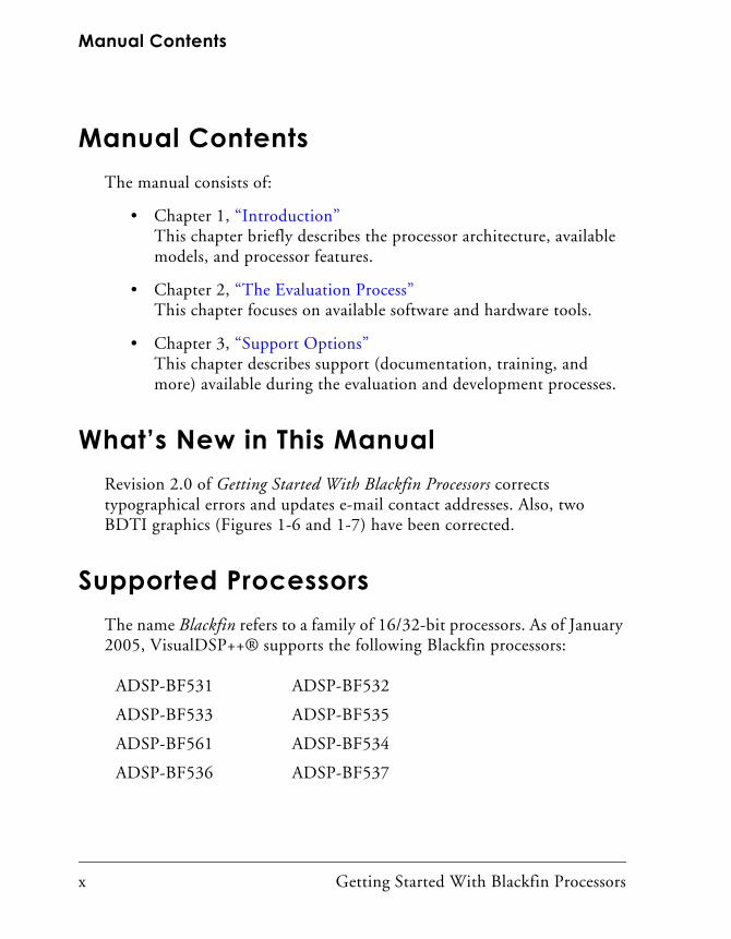
Manual ContentsThe manual consists of:
• Chapter 1, “Introduction” This chapter briefly describes the processor architecture, available models, and processor features.
• Chapter 2, “The Evaluation Process”This chapter focuses on available software and hardware tools.
• Chapter 3, “Support Options”This chapter describes support (documentation, training, and more) available during the evaluation and development processes.
What’s New in This ManualRevision 2.0 of Getting Started With Blackfin Processors corrects typographical errors and updates e-mail contact addresses. Also, two BDTI graphics (Figures 1-6 and 1-7) have been corrected.
Supported ProcessorsThe name Blackfin refers to a family of 16/32-bit processors. As of January 2005, VisualDSP++® supports the following Blackfin processors:
ADSP-BF531 ADSP-BF532
ADSP-BF533 ADSP-BF535
ADSP-BF561 ADSP-BF534
ADSP-BF536 ADSP-BF537

Getting Started With Blackfin Processors xi
Preface
The list of supported Blackfin processors is subject to change. For a com-plete and up to date listing of Blackfin processors refer to www.analog.com/blackfin.
Supported Processors
xii Getting Started With Blackfin Processors

Getting Started With Blackfin Processors 1-1
1 INTRODUCTION
This chapter briefly describes the Blackfin processor’s architecture and key features and compares available models.
Topics include:
• “What are Blackfin Processors?” on page 1-1
• “Blackfin Processor Features” on page 1-10
• “Benchmarking Processors” on page 1-14
What are Blackfin Processors?Blackfin processors embody a new type of 16/32-bit embedded processor designed specifically to meet the computational demands and power con-straints of today’s embedded audio, video, automotive, industrial/instrumentation, and communications applications.
Blackfin processors deliver breakthrough signal processing performance and power efficiency with a RISC programming model. Blackfin proces-sors present high performance, homogeneous software targets, which allow flexible resource allocation between hard real-time DSP tasks and non real-time control tasks. System control tasks can often run in the shadow of DSP and video tasks.
Based on the Micro Signal Architecture (MSA) that Analog Devices jointly developed with Intel® Corporation, Blackfin processors combine a 32-bit RISC instruction set, dual 16-bit multiply accumulate (MAC) digital signal processing functionality, and 8-bit video processing

What are Blackfin Processors?
1-2 Getting Started With Blackfin Processors
performance that had previously been the exclusive domain of very long instruction word (VLIW) media processors.
Blackfin processors include advanced memory management that supports memory-protected and non memory-protected embedded operating sys-tems such as µCLinux, ThreadX® (Express Logic), INTEGRITY® and velOSity™ (Green Hills Software), Nucleus® (Accelerated Technology), Fusion™ (Unicoi Systems), and RTXC Quadros™ (Quadros Systems), to name a few.
The Blackfin processor’s unique combination of processing attributes eliminates the need for separate digital signal and control processors, which reduces bill of material costs and greatly simplifies hardware and software design tasks. Blackfin processors present high performance, homogeneous software targets, which allows flexible resource allocation between demanding real-time DSP tasks and non real-time control tasks.
Combining RISC MCU and DSP FunctionalityBlackfin processors provide both microcontroller (MCU) and DSP func-tionality in a unified architecture, allowing flexible partitioning between the needs of control and signal processing. If the application demands, the Blackfin processor can act as 100% MCU (with code density on par with industry standards), 100% DSP (with clock rates at the leading edge of DSP technology), or a combination of the two.
The Blackfin family of processors from Analog Devices, Inc. integrates a 32-bit RISC instruction set, an 8-bit video instruction set with dual 16-bit MAC units. The processor’s variable length instruction set extends up to 64-bit opcodes used in DSP inner loops (one SIMD and two load/store/cycle), but is optimized so that 16-bit opcodes represent the most frequently used instructions. As a result, compiled code density fig-ures are competitive with industry-leading MCUs, yet its interlocked pipeline and algebraic instruction syntax facilitate development in both C/C++ and assembly.

Getting Started With Blackfin Processors 1-3
Introduction
Figure 1-1 shows a block diagram of a single core ADSP-BF533 Blackfin 16/32-bit processor.
Blackfin processors support both protected and unprotected operating modes that prevent users from accessing or affecting shared parts of the system. In addition, the processors provide memory management capabil-ities that enable users to define separate application development spaces. This design feature prevents distinct code sections from being overwritten. At the same time, the Blackfin architecture allows asynchronous interrupts
Figure 1-1. Single Core ADSP-BF533 Blackfin 16/32-Bit Processor
CORE
SYSTEM INTERFACE UNIT
L1 MEMORY
16-BITEXTERNAL
BUSINTERFACEJTAG VOLTAGE
REGULATOREVENT
CONTROLLERWATCHDOG
TIMERMEMORY
DMA
SYSTEM CONTROL BLOCKS
SPORT0
REAL TIMECLOCK PLL
SRAM / CACHE.
SPORT1
PPI/GPIO
UART
IrDASPITIMERS
(3)
HIGH SPEED I/O
64KBDATA
80KBINST
B
PERIPHERALBLOCKS

What are Blackfin Processors?
1-4 Getting Started With Blackfin Processors
and synchronous exceptions, as well as programmable interrupt priorities. Thus, Blackfin processors are well suited as targets for embedded operat-ing systems.
Approaches to Application Development
Blackfin processors have a peripheral set that supports high speed serial and parallel data movement. In addition, Blackfin processors include an advanced power management feature set that allows system architects to craft designs with low dynamic power profiles.
In today’s design model, MCU and traditional DSP programmers often partition their code development into two separate groups, interacting only at the system boundary level where their two functional worlds meet. This makes some sense, as two separate groups of designers can develop their own sets of design practices based on application requirements. For instance, signal processing developers may want to implement techniques to improve performance. Another group may have opposing design goals—MCU programmers, for example, may prefer implementing a turn-key system and letting it perform all tasks without user intervention.
With this in mind, Blackfin processors were designed to support both DMA and cache memory controllers to move data through a system. Mul-tiple high speed DMA channels shuttle data between peripherals and memory systems, allowing the fine tuning controls sought by DSP pro-grammers without using up valuable core processor cycles. Conversely, on-chip configurable instruction and data caches allow a hands off approach to managing code and data in a manner very familiar to MCU programmers. Often, at the system integration level, a combination of both approaches is ideal.
Another reason for the historical separation of MCU and DSP develop-ment groups is that the two processors have two separate sets of design imperatives. From a technical standpoint, engineers responsible for archi-tecting a system often hesitate to mix a “control” application with a “signal processing” application on the same processor. Their most
Getting Started With Blackfin Processors 1-5
Introduction
common fear is that non real-time tasks interfere with hard real-time tasks. For instance, programmers who handle tasks such as the graphical user interface (GUI) or the networking stack should not have to worry about hampering the system’s real-time signal processing activities. Of course, the definition of real time varies based on the specific application. In an embedded application, the focus is on the time required to service an interrupt. For this purpose, assume there is a time frame of less than 10 microseconds between an interrupt and the time that the system context is saved at the start of the service routine.
With the introduction of the Blackfin processors, a C/C++-centric unified code base can be realized. This enables developers to leverage enormous amounts of existing application code developed from previous efforts. Because Blackfin processors are optimized for both control and signal pro-cessing operations, compilers can generate code that is both tight (from a code density standpoint) and efficient (for computationally intensive sig-nal processing applications). Of course for veteran programmers, targeted assembly coding is still an option for optimizing critical processing loops.
Operating system (OS) support is also key. Several layers of tasking can be realized by supporting an operating system or real-time kernel. An inter-rupt controller that supports multiple priority levels is needed to ensure that targeted performance is still achievable. Context switching must be attainable through hardware-based stack and frame pointer support. This enables developers to create systems that include both worlds—control and real-time signal processing—on the same device.
In addition, the Blackfin processors’ memory management facility permits OS support for memory protection. This allows one task, via a paging mechanism, to block memory or instruction accesses by another task. An exception is generated whenever unauthorized access is made to a pro-tected area of memory. The kernel services this exception and takes appropriate action.

What are Blackfin Processors?
1-6 Getting Started With Blackfin Processors
The high processing speeds achieved by Blackfin processors translate into several tangible benefits. The first is time to market. There can be consid-erable savings in reducing or bypassing the code optimization effort when there is plenty of processing capacity to spare. A second benefit is reduced software maintenance, which can otherwise dominate a product’s life cycle cost. Finally, for scalable Blackfin architectures, designers can base a design around the most capable member of the Blackfin processor family, and can later “right-size” the processor to the final application’s computa-tional footprint.
Dual-Core Processors Add Flexibility
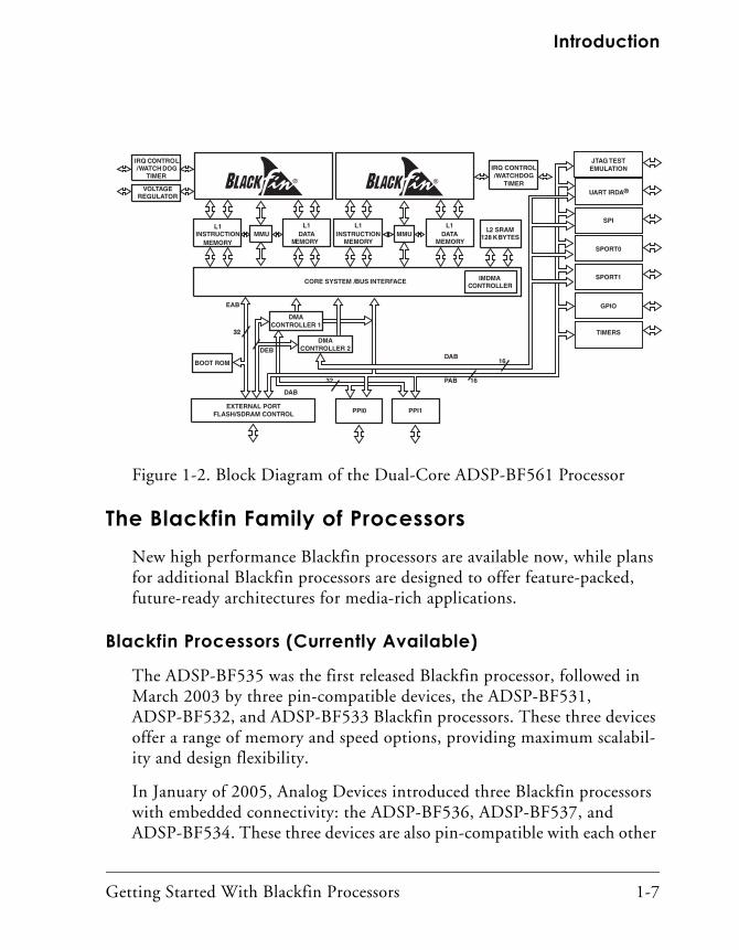
Blackfin processors are also available as dual-core devices. The traditional use of a dual-core processor employs discrete and often different tasks that run on each of the cores. For example, one core might perform all of the control-related tasks, such as graphics and overlay functionality, network-ing, interfacing to bulk storage, and overall flow control. This core is also where the operating system or kernel most likely resides. Meanwhile, the second core is dedicated to the application’s high-intensity processing functions. For example, compressed data packets might be transferred over a network interface to the first core for preprocessing, and then passed to the second core for audio and video decoding. Figure 1-2 shows a block diagram of a typical dual-core processor.
The use of a dual-core processor is preferred for designs built by separate software development teams. The ability to segment these types of func-tions allows a parallel design process, eliminating critical path dependencies in the project. This programming model also aids the testing and validation phases of the project. For example, a code change on one core does not necessarily invalidate the testing efforts already completed on the other core.
Getting Started With Blackfin Processors 1-7
Introduction
The Blackfin Family of ProcessorsNew high performance Blackfin processors are available now, while plans for additional Blackfin processors are designed to offer feature-packed, future-ready architectures for media-rich applications.
Blackfin Processors (Currently Available)
The ADSP-BF535 was the first released Blackfin processor, followed in March 2003 by three pin-compatible devices, the ADSP-BF531, ADSP-BF532, and ADSP-BF533 Blackfin processors. These three devices offer a range of memory and speed options, providing maximum scalabil-ity and design flexibility.
In January of 2005, Analog Devices introduced three Blackfin processors with embedded connectivity: the ADSP-BF536, ADSP-BF537, and ADSP-BF534. These three devices are also pin-compatible with each other
Figure 1-2. Block Diagram of the Dual-Core ADSP-BF561 Processor
VOLTAGEREGULATOR
IRQ CONTROL/WATCH DOG
TIMER
EXTERNAL PORTFLASH/SDRAM CONTROL
32
1632
16BOOT ROM
PAB
EAB
DAB
DAB
PPI0 PPI1
JTAG TESTEMULATION
GPIO
SPI
UART IRDA®
SPORT0
TIMERS
SPORT1IMDMACONTROLLER
L1INSTRUCTION
MEMORY
L1DATA
MEMORYMMU
BL2 SRAM
128 KBYTES
CORE SYSTEM /BUS INTERFACE
L1INSTRUCTION
MEMORY
L1DATA
MEMORYMMU
B
DMACONTROLLER 1
DMACONTROLLER 2
IRQ CONTROL/WATCHDOG
TIMER
DEB

What are Blackfin Processors?
1-8 Getting Started With Blackfin Processors
and include Controller Area Network (CAN), Twin-Wire Interface (TWI) peripherals, and on some models, a 10/100 Ethernet MAC. Each of these first generation Blackfin devices (the ADSP-BF535, ADSP-BF531, ADSP-BF532, ADSP-BF533, ADSP-BF536, ADSP-BF537, and ADSP-BF534) released by January 2005 is a sin-gle-core processor.
Analog Devices also developed a dual-core symmetric multiprocessor, the ADSP-BF561. This new processor uses a dual-core processor instead of a single-core processor and increases performance without switching proces-sor architectures. In fact, by running both processor cores at lower frequencies and lower voltages, power consumption is lowered. The advantages of this technique are described in “Dual-Core Processors Add Flexibility” on page 1-6.
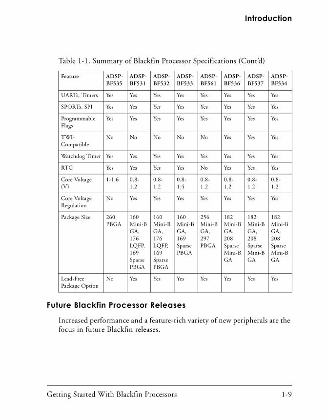
Each Blackfin processor provides unique capabilities, while being pin-compatible with other Blackfin devices. Table 1-1 lists key Blackfin processor specifications. View the Blackfin processor selection table online at the Analog Devices Web site at:
http://www.analog.com/blackfin.
Table 1-1. Summary of Blackfin Processor Specifications
Feature ADSP-BF535
ADSP-BF531
ADSP-BF532
ADSP-BF533
ADSP-BF561
ADSP-BF536
ADSP-BF537
ADSP-BF534
Max. Clock Speed (MHz)
350 400 400 750 600 400 600 500
Memory (Kbytes)
308 52 84 148 328 100 132 132
ExternalMemory (Bus)
32-bit 16-bit 16-bit 16-bit 32-bit 16-bit 16-bit 16-bit
ParallelPeripheral Interface
No Yes Yes Yes Yes (2) Yes Yes Yes
Getting Started With Blackfin Processors 1-9
Introduction
Future Blackfin Processor Releases
Increased performance and a feature-rich variety of new peripherals are the focus in future Blackfin releases.
UARTs, Timers Yes Yes Yes Yes Yes Yes Yes Yes
SPORTs, SPI Yes Yes Yes Yes Yes Yes Yes Yes
Programmable Flags
Yes Yes Yes Yes Yes Yes Yes Yes
TWI-Compatible
No No No No No Yes Yes Yes
Watchdog Timer Yes Yes Yes Yes Yes Yes Yes Yes
RTC Yes Yes Yes Yes No Yes Yes Yes
Core Voltage (V)
1-1.6 0.8-1.2
0.8-1.2
0.8-1.4
0.8-1.2
0.8-1.2
0.8-1.2
0.8-1.2
Core Voltage Regulation
No Yes Yes Yes Yes Yes Yes Yes
Package Size 260 PBGA
160 Mini-BGA,176 LQFP,169 Sparse PBGA
160 Mini-BGA,176 LQFP,169 Sparse PBGA
160 Mini-BGA,169 Sparse PBGA
256 Mini-BGA,297 PBGA
182 Mini-BGA, 208 Sparse Mini-BGA
182 Mini-BGA, 208 Sparse Mini-BGA
182 Mini-BGA, 208 Sparse Mini-BGA
Lead-FreePackage Option
No Yes Yes Yes Yes Yes Yes Yes
Table 1-1. Summary of Blackfin Processor Specifications (Cont’d)
Feature ADSP-BF535
ADSP-BF531
ADSP-BF532
ADSP-BF533
ADSP-BF561
ADSP-BF536
ADSP-BF537
ADSP-BF534

Blackfin Processor Features
1-10 Getting Started With Blackfin Processors
Blackfin Processor FeaturesBlackfin processors represent a new class of devices that combine an extremely capable Single Instruction, Multiple Data (SIMD) processor engine with powerful features such as a Memory Management Unit (MMU), watchdog timer, real-time clock, variable length RISC instruc-tions, UARTs, and SPI ports. These features are typically found only in microcontrollers and microprocessors.
Because Blackfin processors possess all the power of a DSP and are full featured, they can replace other classes of DSPs and 32-bit RISC MCU (or an ASIC) in designs.
At the core, Blackfin processors have a 16-bit, dual MAC (multiply accu-mulate) architecture with 32-bit registers and 64-bit internal data paths. This core is surrounded by high speed memory and high speed peripherals including 100 Mbps serial ports (SPORTs), a high speed parallel periph-eral interface (PPI) capable of moving digital video on and off chip (ITU-R/CCIR-656 compliant), UART with IRDA support, SPI port, and an external memory interface for connection to SDRAM, FLASH, SRAM, and so on.
In addition to its advanced peripherals, Blackfin processors include an on-chip switching regulator and a software programmable on-chip phase lock loop (PLL) that allows software to control the core clock speed and core voltage. This can result in huge power savings because you can con-stantly vary the clock and voltage, depending on the task at hand.
Since Blackfin processors can be used for both control/data processing and signal processing, the efficiency of data movement and storage has a high impact on performance. Efficient numerical precision ranks high on the list of important features, although efficiency of data movement is equally as important. The width of a signal processing device is often measured based on the type of data it processes most efficiently. The width of a pro-cessor is typically measured by its data paths and register widths. Blackfin processors support 8-, 16-, and 32-bit arithmetic operations in hardware,

Getting Started With Blackfin Processors 1-11
Introduction
but they are optimized for (and have the most support for) 16-bit opera-tions. Thus, Blackfin processors are considered to be 16/32-bit processors.
Three additional reasons explain why Blackfin processors are currently unmatched in the industry:
• Performance
• Low Power Consumption
• Low Cost
PerformanceProcessors can no longer be judged solely on core clock speed, MHz, MIPS, MACS, FLOPS, BLOPs, FROGs, TOADs, and so on. Newer Blackfin processors run at core clock frequencies starting at 300 MHz. All of its internal memory is L1, which means that memory also runs at the core clock rate, providing large amounts of bandwidth between the pro-cessor’s core and its internal memory. The core supports two 16-bit multiply accumulates per cycle sustained, providing 1.2 GMACs at 600 MHz.
Although these numbers provide a rough idea of a device’s performance, they do not measure how an application runs on a device because they do not take into account memory efficiency or instruction set efficiency. Often, these peak specifications occur only momentarily (that is, they are not sustained), and the sustained values are much lower. This is where benchmark data can be useful. “Benchmarking Processors” on page 1-14 describes performance measurements reported by third parties.
Figure 1-3 shows a chart that demonstrates power consumption versus speed for ADSP-BF561 Blackfin processors and various devices.
System developers can leverage the wide range of performance options available with Blackfin processors. Lower frequency, signal-core devices scale up to high frequency, high bandwidth, dual-core devices.

Blackfin Processor Features
1-12 Getting Started With Blackfin Processors
ADSP-BF561 Blackfin processors provide additional options for power management. Because this symmetric processor contains two identical cores, traditional processing-intensive applications can be split equally to run on each of the two cores. In this model, code running on each core is identical; only the data being processed is different. In a channel stream-ing application, the first core processes half of the channels and the other core processes the other channels. In video and imaging applications, this technique can be used to process alternate frames on each of the cores.
Dual-core processing melds with the Blackfin processors’ additional power savings features. The energy consumed by a processor is based on both static and dynamic components. Even when the application fits on a sin-gle-core processor, you can employ a dual-core processor to reduce overall
Figure 1-3. Power Consumption Versus Speed for Various Devices
400
200
600
800
1000
1400
1200
00 200 600 1000 1400 1800 300016002200 3400
MMACs
MOTOROLAMSC8103 (300 MHz)
TEXAS INSTRUMENTSTMS320VC5502 (300 MHz)
MOTOROLADSP56371(180 MHz)
ANALOG DEVICESADSP-BF533750MHzP
OW
ER
(mW
)
TEXAS INSTRUMENTSTMS3206414 (720 MHz)
TEXAS INSTRUMENTS320DM642 (600 MHz)
B
TEXAS INSTRUMENTSTMS320VC5509A(200 MHz)
ANALOG DEVICESADSP-BF561750MHz
B

Getting Started With Blackfin Processors 1-13
Introduction
energy consumption. Specifically, by running an application at half the frequency of a single-core system, the processor core voltages can also be dropped to values as low as 0.8 V. This is possible because of the Blackfin processors’ wide voltage operating range. Dual-core Blackfin processors contain large amounts of on-chip memory along with data paths and DMA controllers that have been sized specifically to handle a shared pro-cessing load. This combination allows an algorithm to be split easily without the loss of efficiency that can be felt on multicore solutions with different processors.
Low Power ConsumptionWhen a portable battery-powered application needs to run for a long period of time or when designers need their systems to wake up periodi-cally and perform various tasks then return to a deep sleep, the low power states of Blackfin processors can be effectively used. Because Blackfin pro-cessors are implemented in a 0.13µm CMOS process, they can dissipate approximately half the power of its closest competition. In a comparison to similar processors, Figure 1-4 illustrates how efficiently a Blackfin pro-cessor conserves power.
At 600 MHz, the processor core dissipates only 280 mW of power. How-ever, at 300 MHz, this drops to 90 mW, and at 200 MHz, to around 50 mW. Measurements are based on a 75% dual-MAC, 25% ADD, moderate data load.
By using the on-chip power management features (programmable voltage regulator and PLL, and low power modes), you can maximize battery life by using only as much processing power as required.
Figure 1-5 shows a 43% power gain from using a Blackfin processor in comparison to competitor’s processors.

Benchmarking Processors
1-14 Getting Started With Blackfin Processors
Low CostBlackfin processors are priced starting at $4.95/each in 10K unit quanti-ties for 400 MHz operation. At this price point, Blackfin processors offer unprecedented processing power for the cost.
Benchmarking ProcessorsWhen evaluating processors, it can be confusing to look at data sheets and compare the specifications. We recommend that you refer to the findings of independent groups who evaluate processors.
Figure 1-4. Conserving Power
2x PERFORMANCEAT SAME POWER LEVEL
ADSP-BF533
TI '5502/1
TI '5510
2000 400 600 800
300
250
200
150
100
50
0
FREQUENCY (MHz)
PO
WE
R(m
W)
50% OF POWER @ 300 MHz
30% OF POWER @ 200 MHz
B

Getting Started With Blackfin Processors 1-15
Introduction
Berkeley Design Technology Incorporated (BDTI) and Embedded Micro-processor Benchmark Consortium (EEMBC) specialize in evaluating processor performance. Their findings are presented in the following sections.
BDTIIf your application requires a great deal of signal processing, examine the BDTI Benchmark™ results.
The following paragraphs taken from the BDTI Web site describe their evaluation process and conclusions.
At BDTI, we have benchmarked and analyzed the DSP capabilities of a wide range of DSPs, general-purpose processors, and other processing devices such as FPGAs and configurable processors. We have extensive experience with all aspects of DSP benchmarking and evaluation, and we can put that experience to work for
Figure 1-5. Power Savings With the ADSP-BF561Blackfin Processor
1200
1000
800
600
400
200
0
PO
WE
R(m
W)
0
MMACs
400 800 1200 1600 2000 2400 2800 3200 3600
ADSP-BF531/2/3 ADSP-BF561
43% GAIN IN MMACsAT THE SAME POWER

Benchmarking Processors
1-16 Getting Started With Blackfin Processors
you. By adopting the BDTI Benchmark methodology, vendors may compare their products with dozens of other processor architectures, providing an unparal-leled resource for product positioning and targeting.
The BDTI Benchmarks
In 1994, BDTI introduced its core suite of DSP benchmarks, called the BDTI Benchmarks™, a vendor-independent and unique benchmarking methodology. The BDTI Benchmarks are a suite of twelve algorithm kernels which represent key DSP operations. The BDTI Benchmarks were revised and expanded in 2000, increasing their value for users and developers of processors targeting DSP appli-cations. The BDTI Benchmarks have now been applied to dozens of processor architectures, providing systems designers and OEMs with an unparalleled body of information to use in making decisions regarding the selection of a processor for a particular application or, for processor designers, in the design of a new architecture.1
About the Scores
The BDTImark2000™ is a summary measure of processors’ signal processing speed distilled from a suite of signal processing benchmarks developed and inde-pendently verified by Berkeley Design Technology, Inc. A higher score indicates a faster processor.
Because it is based on realistic benchmarks, the BDTImark2000 characterizes a processor’s signal processing speed far more accurately than simplified measures such as millions of multiply-accumulates per second (MMACS).
BDTI’s policy is to verify benchmark results on silicon before issuing a BDTImark2000 score. This policy helps to ensure that the score accurately reflects the performance that can be expected from actual silicon available today.
However, it is not always practical to verify benchmarks on hardware. For exam-ple, a chip designer may need to evaluate a licensable core before the core has been fabricated. To meet such needs, BDTI publishes the BDTIsimMark2000™. This metric is calculated in the same manner as the BDTImark2000, but is based on simulated results instead of hardware measurements.
1 Excerpted from http://www.bdti.com/products/services_benchmarking.html. © 2004 BDTI.

Getting Started With Blackfin Processors 1-17
Introduction
Although BDTIsimMark2000 and BDTImark2000 scores are calculated in the same manner, they should be compared with caution. In addition, caution should be used when comparing scores for chips to scores for cores.
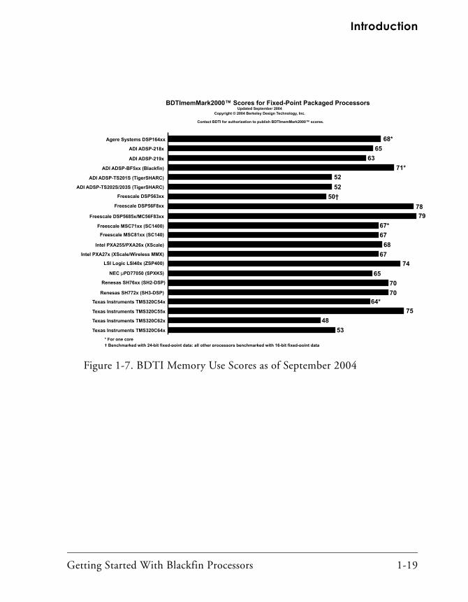
The BDTImemMark2000™ is a summary measure of processors’ memory effi-ciency on signal processing applications. The BDTImemMark2000 is based on the same suite of signal processing benchmarks as the BDTImark2000 and BDTIsimMark2000. A higher BDTImemMark2000 score indicates a more effi-cient processor. That is, a higher BDTImemMark2000 score indicates lower memory use. Memory efficiency is important for two reasons: first, a processor’s memory efficiency has a significant impact on overall system cost and energy con-sumption. Second, a processor may experience significant performance degradation if frequently-accessed application code and data do not fit in level-one memory.1
Using their benchmark scores, BDTI compares devices with regard to power consumption, speed, and price. Figure 1-6 (from November 2004) looks at processor speed. Figure 1-7 examines memory use. Clearly, Black-fin processors are highly competitive.
To learn more about the BDTI Benchmarks and find out how Blackfin processors perform against the competition, go to the following BDTI Web page: http://www.BDTI.com/benchmarks.html.
1 Excerpted from http://www.bdti.com/benchmarks.html. © 2004 BDTI

Benchmarking Processors
1-18 Getting Started With Blackfin Processors
Figure 1-6. BDTI Comparisons as of November 2004: Processor Speed
Texas Instruments TMS320C62x (300 MHz)
ADI ADSP-BF5xx (Blackfin) (750 MHz)
ADI ADSP-TS201S (TigerSHARC) (600 MHz)
Freescale DSP563xx (275 MHz)
1360*
240
4190*
410
6400
5130
820†
110
340
2240
4490*
930
2140
940
1770
280
500*
1460
1920
9130
Agere Systems DSP164xx (285 MHz)
ADI ADSP-218x (80 MHz)
ADI ADSP-TS202S/203S (TigerSHARC) (500 MHz)
ADI ADSP-219x (160 MHz)
Freescale MSC81xx (SC140) (400 MHz)
Freescale DSP56F8xx (80 MHz)
Freescale DSP5685x/MC56F83xx (120 MHz)
Freescale MSC71xx (SC1400) (200 MHz)
Intel PXA255/PXA26x (XScale) (400 MHz)
Intel PXA27x (XScale/Wireless MMX) (624 MHz)
LSI Logic LSI40x (ZSP400) (200 MHz)
NEC µPD77050 (SPXK5) (250 MHz)
Renesas SH76xx (SH2-DSP) (100 MHz)
Renesas SH772x (SH3-DSP) (200 MHz)
Texas Instruments TMS320C54x (160 MHz)
Texas Instruments TMS320C55x (300 MHz)
Texas Instruments TMS320C64x (1 GHz)
* For one core
† Benchmarked with 24-bit fixed-point data; all other processors benchmarked with 16-bit fixed-point data
BDTIsimMark2000™ scores may be based on
projected clock speeds. For information, visit:
www.BDTI.com/benchmarks.html‡ Projected
BDTImark2000™
BDTIsimMark2000™
BDTImark2000™/BDTIsimMark2000™ Scores for Fixed-Point Packaged ProcessorsUpdated November 2004
Copyright © 2004 Berkeley Design Technology, Inc.
Contact BDTI for authorization to publish BDTImark2000™/BDTIsimMark2000™ scores.
Freescale MSC81xx (SC140) (500 MHz) 5610*‡
490
Getting Started With Blackfin Processors 1-19
Introduction
Figure 1-7. BDTI Memory Use Scores as of September 2004
74
Texas Instruments TMS320C62x
ADI ADSP-BF5xx (Blackfin)
ADI ADSP-TS201S (TigerSHARC)
Freescale DSP563xx
68*
65
71*
63
52
50†
78
79
67*
Agere Systems DSP164xx
ADI ADSP-218x
ADI ADSP-TS202S/203S (TigerSHARC)
ADI ADSP-219x
Freescale MSC81xx (SC140)
Freescale DSP56F8xx
Freescale DSP5685x/MC56F83xx
Freescale MSC71xx (SC1400)
Intel PXA255/PXA26x (XScale)
Intel PXA27x (XScale/Wireless MMX)
LSI Logic LSI40x (ZSP400)
NEC µPD77050 (SPXK5)
Renesas SH76xx (SH2-DSP)
Renesas SH772x (SH3-DSP)
Texas Instruments TMS320C54x
Texas Instruments TMS320C55x
Texas Instruments TMS320C64x
* For one core
† Benchmarked with 24-bit fixed-point data; all other processors benchmarked with 16-bit fixed-point data
BDTImemMark2000™ Scores for Fixed-Point Packaged ProcessorsUpdated September 2004
Copyright © 2004 Berkeley Design Technology, Inc.
Contact BDTI for authorization to publish BDTImemMark2000™ scores.
52
67
67
68
74
65
53
48
70
64*
75
70

Benchmarking Processors
1-20 Getting Started With Blackfin Processors
EEMBCIf the application demands both the performance of a signal processing engine and a microcontroller, examine what the Embedded Microproces-sor Benchmark Consortium (EEMBC) says about Blackfin processors.
The following paragraphs are taken from the EEMBC Web site.
EEMBC, the Embedded Microprocessor Benchmark Consortium, was formed in 1997 to develop meaningful performance benchmarks for the hardware and soft-ware used in embedded systems. Through the combined efforts of its members, EEMBC® benchmarks have become an industry standard for evaluating the capa-bilities of processors, compilers, and Java implementations according to objective, clearly defined, application-based criteria.
Since releasing its first certified benchmark scores in April 2000, EEMBC scores have effectively replaced the obsolete Dhrystone mips, especially in situations where real engineering value is important. EEMBC benchmarks reflect real-world applications and the demands that embedded systems encounter in these environ-ments. The result is a collection of “algorithms” and “applications” organized into benchmark suites targeting telecommunications, networking, digital media, Java, automotive/industrial, consumer, and office equipment products. An additional suite of algorithms specifically targets the capabilities of 8- and 16-bit microcontrollers.
EEMBC’s certification rules represent another break with the past. For a proces-sor’s scores to be published, the EEMBC Certification Laboratories (ECL) must execute benchmarks run by the manufacturer. ECL certification ensures that scores are repeatable, obtained fairly, and according to EEMBC’s rules. Scores for devices that have been tested and certified by ECL can be searched from our Benchmark Search page.
To find out more about how Blackfin processors perform compared to the competition, go to the following EEMBC Web page:
http://www.eembc.org.

Getting Started With Blackfin Processors 1-21
Introduction
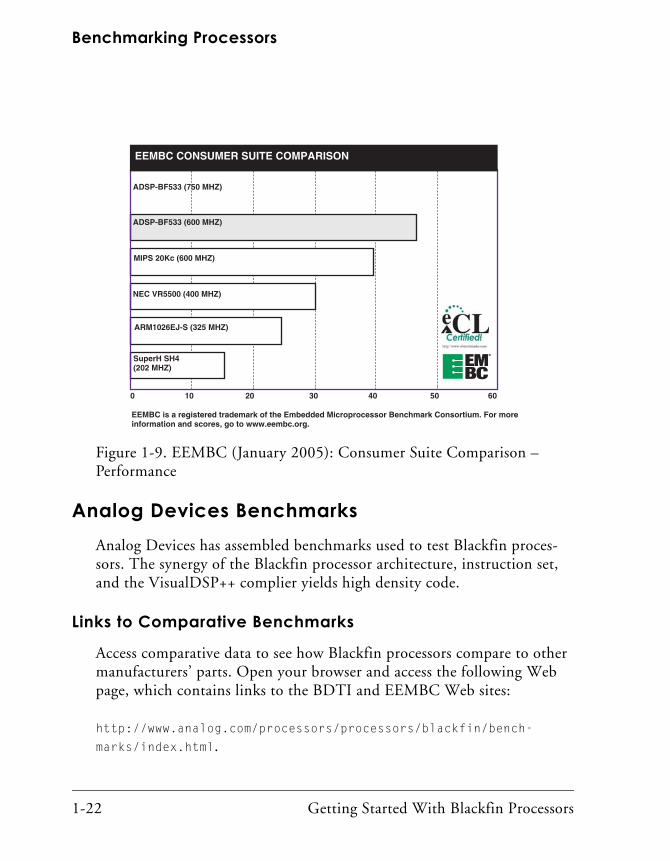
Based on recent EEMBC data, Figure 1-8 compares code density, and Figure 1-9 focuses on performance.
Figure 1-8. EEMBC: Consumer Suite Comparison – Code Density as of January 2005
MIPS 20kC
IBM 405GPr
NEC VR5500
SuperH SH4
ARM 1029EJ-S
INFINEON TriCore
ADSP-BF533
0 2000 4000 1000080006000
SMALLER IS BETTER
Benchmarking Processors
1-22 Getting Started With Blackfin Processors
Analog Devices BenchmarksAnalog Devices has assembled benchmarks used to test Blackfin proces-sors. The synergy of the Blackfin processor architecture, instruction set, and the VisualDSP++ complier yields high density code.
Links to Comparative Benchmarks
Access comparative data to see how Blackfin processors compare to other manufacturers’ parts. Open your browser and access the following Web page, which contains links to the BDTI and EEMBC Web sites:
http://www.analog.com/processors/processors/blackfin/bench-
marks/index.html.
Figure 1-9. EEMBC (January 2005): Consumer Suite Comparison – Performance
MIPS 20Kc (600 MHZ)
ARM1026EJ-S (325 MHZ)
SuperH SH4(202 MHZ)
NEC VR5500 (400 MHZ)
ADSP-BF533 (600 MHZ)
ADSP-BF533 (750 MHZ)
0 10 20 604030 50
EEMBC CONSUMER SUITE COMPARISON
EEMBC is a registered trademark of the Embedded Microprocessor Benchmark Consortium. For moreinformation and scores, go to www.eembc.org.

Getting Started With Blackfin Processors 1-23
Introduction
Code Examples
Specific code examples for many DSP algorithms optimized for Blackfin processors are currently available. The code examples are contained in .ZIP files available from the following Web page:
http://www.analog.com/processors/processors/blackfin/technicalL-
ibrary/manuals/codeExamples.html.
The examples are grouped into the following categories: multi-rate filters, Fourier and discrete cosine function sets, convolution encoder sets, speech- and audio-related algorithms, image processing function sets, image analysis, video into audio/video, and so on.
The code examples work with VisualDSP++ 3.5 and VisualDSP++ 4.0.
To receive automatic notification by e-mail when any of these code examples are updated, register for myAnalog.com and select Blackfin as the “product category” and Code Examples as the “publication type.”
Examples Included With VisualDSP++
VisualDSP++ includes scores of examples built for Blackfin processors. One folder contains programs for signal processing, overlays, scripting, VDK, BTC, and more. Another folder provides example programs that run on EZ-KIT Lite® evaluation systems.
The programs help you learn about processor core and peripherals, audio effects, signal processing, video and graphics, kernel and operating sys-tems, and automation and scripting.
Device Drivers and System Services
Powerful system services are available to applications through the System Services Library, which can be used to control the Blackfin processor’s dynamic power management capabilities as well as control external asyn-chronous and synchronous memories, and manage interrupt processing.

Benchmarking Processors
1-24 Getting Started With Blackfin Processors
Applications can utilize the services of the DMA and callback services to easily schedule both peripheral and memory DMA transfers, and defer non-critical event-driven processing to a lower priority.
Blackfin Processor Compiler and Code Density
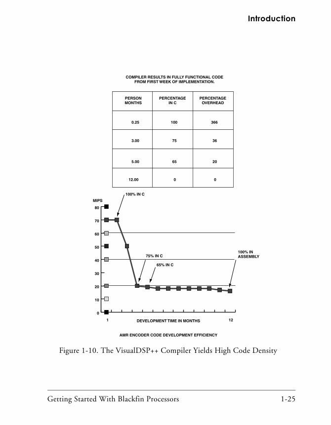
Blackfin processors coupled with the powerful new VisualDSP++ software development tools now make it possible to develop code in C/C++ more easily and efficiently than before. The high MIPS availability from the core processor allows for initial versions of software to be compiled and run on the processor much earlier in the design cycle, thus allowing for quicker overall system debug to shorten time to market. The goal is to alleviate software as a potential critical path element in system development.
Figure 1-10 shows an example of the code development efficiency on Blackfin processors using an Adaptive Multi-Rate (AMR) encoder.
Getting Started With Blackfin Processors 1-25
Introduction
Figure 1-10. The VisualDSP++ Compiler Yields High Code Density
MIPS
1 12DEVELOPMENT TIME IN MONTHS
AMR ENCODER CODE DEVELOPMENT EFFICIENCY
100% IN C
75% IN C
65% IN C
100% INASSEMBLY
PERSONMONTHS
PERCENTAGEIN C
PERCENTAGEOVERHEAD
0.25
3.00
5.00
100
75
65
012.00
366
36
20
0
COMPILER RESULTS IN FULLY FUNCTIONAL CODEFROM FIRST WEEK OF IMPLEMENTATION.
0
10
20
30
40
50
60
70
80

Benchmarking Processors
1-26 Getting Started With Blackfin Processors

Getting Started With Blackfin Processors 2-1
2 THE EVALUATION PROCESS
This chapter describes the available software and hardware tools needed to evaluate Blackfin processors and develop application programs.
This chapter consists of:
• “DSP Project Development Stages” on page 2-1This section provides an overview of typical steps followed in a project development life cycle.
• “Evaluation Tools” on page 2-3This section introduces the software and hardware tools that are currently available including:
• “Selecting Software Development Tools” on page 2-4
• “Deciding Whether or Not to Use an RTOS” on page 2-12
• “Selecting the Right Combination of Tools” on page 2-39
DSP Project Development StagesThe typical project includes three phases: simulation, evaluation, and emulation. These phases are shown in Figure 2-1.
You use VisualDSP++ during both simulation and emulation.

DSP Project Development Stages
2-2 Getting Started With Blackfin Processors
SimulationProject development typically begins in a simulation environment while hardware engineers are developing the new hardware (cell phone, com-puter, and so on). Simulation mimics system memory and I/O, which enables portions of the target system hardware to be viewed. A simulator is software that mimics the behavior of a DSP chip. Running VisualDSP++ with a simulation target without a physical processor enables you to build, edit, and debug your DSP program before a DSP chip is manufactured.
Figure 2-1. Project Development Stages
SIMULATION
EVALUATION
EMULATION
NO HARDWARE REQUIRED
USBEZ-KIT LITE
B
POD
ACTUAL BOARD
B

Getting Started With Blackfin Processors 2-3
The Evaluation Process
EvaluationUse an EZ-KIT Lite evaluation system in your project’s early planning stages to determine the processor that best fits your needs. Your PC con-nects to the EZ-KIT Lite board via a cable, which enables you to monitor processor behavior.
EmulationOnce the hardware is ready, move directly to a JTAG emulator, the hardware that connects your PC to the actual processor target board. An emulator enables application software to be downloaded and debugged from within VisualDSP++. Emulator software performs the communica-tions that enables you to see how your DSP code affects DSP performance.
Evaluation ToolsThis section examines the process through which Blackfin processor applications are developed. Various tools are used at each stage. Typical application development occurs over multiple stages.
Most users acquire a set of software development tools first. The software development tools run on a PC and provide code generation and debug utilities such as a compiler, assembler, linker, simulator, debugger, and libraries. Selecting appropriate software involves:
• “Selecting Software Development Tools” on page 2-4
• “Deciding Whether or Not to Use an RTOS” on page 2-12
Optionally, users acquire a hardware tool to begin testing the application on a Blackfin processor. Development boards typically provide expansion headers, allowing you to prototype basic hardware without customized user hardware.

Evaluation Tools
2-4 Getting Started With Blackfin Processors
“Selecting Software Development Tools”, provides a summary of the available software development tools for Blackfin processors. Most devel-opment tools available for Blackfin processors provide a cycle accurate simulator which can develop initial algorithms and applications without the actual hardware.
Selecting Software Development ToolsBecause Blackfin processors are programmable, software development tools are required to author software applications. Typical software development tools include a C/C++ compiler, run-time libraries, assem-bler, and a linker. Emulation, simulation, debugging, and project management capabilities vary, based on the tools vendor. The process of selecting tools is shown in Figure 2-2 on page 2-5.
Currently, three sets of software development tools are available for the Blackfin processor architecture:
• VisualDSP++ 4.0 from Analog Devices
• MULTI® from Green Hills Software
• Open Source GCC tool chain and µClinux
Each offers advantages for different types of applications. This document focuses on the Analog Devices VisualDSP++ tool chain, which is the most popular set of tools and provides the best starting point for new users.
Other software development tools are available in languages such as Japa-nese and Chinese. Contact your local Analog Devices sales office or distributor for more information.
VisualDSP++ From Analog Devices, Inc.
VisualDSP++ is an easy to install and easy to use integrated software devel-opment and debugging environment (IDDE) that enables efficient management of projects from start to finish from within a single interface.

Getting Started With Blackfin Processors 2-5
The Evaluation Process
Figure 2-2. Tool Selection Workflow
DECIDE TO EVALUATE BLACKFIN
PURCHASESTAMP BOARD
DOWNLOAD"GNU" TOOLS
PURCHASEEZ-KIT LITE
DOWNLOAD"TestDrive"
OBTAIN GHSSOFTWARE
YES
NO
2
VALIDATECONCEPT
3
4
1DOWNLOAD THE "TestDrive"VERSION OF VisualDSP++
- 90-DAY LICENSE
- SIMULATION ONLY
1
PURCHASE APIEXTENDER CARDS?
2
DOWNLOAD CAD FILESFROM ADI?
3
BUILD CUSTOMHARDWARE?
4
YES
NO
YES
NO
PURCHASEVisualDSP++
LICENSE
DESIGN/TEST/DEBUG SYSTEM
SHIP PRODUCTS
DESIGN AND BUILD CUSTOMHARDWARE, FIRMWARE ANDSOFTWARE.
PURCHASE JTAG EMULATORAND DEBUG (THIS IS AN ITERATIVEPROCESS)
5
5
OPTIONAL STEPS

Evaluation Tools
2-6 Getting Started With Blackfin Processors
Because project development and debugging is integrated, you can move quickly and easily between editing, building, and debugging activities. Key features include the native C/C++ compiler, advanced graphical plot-ting tools, statistical profiling, and the VisualDSP++ Kernel (VDK), which allows a user’s code to be implemented in a more structured and easier to scale manner. Other features include assembler, linker, libraries, splitter, cycle-accurate and functional-accurate compiled simulators, emu-lator support, and more. VisualDSP++ offers programmers a powerful yet easy to use programming tool with flexibility that significantly reduces the time to market.
Platform and Processor Support. VisualDSP++ supports Blackfin, SHARC®, and TigerSHARC® processors on Windows 2000 and Windows XP.
Robust and Flexible Project Management. The IDDE provides robust and flexible project management for the development of applications and includes access to all of the activities necessary to create and debug projects. It enables you to open and switch between multiple projects in the same session. A project group that contains any number of projects can be saved to a file so that the same set of projects can be conveniently opened in any other work space at a later time.
Time-Saving Debugger. The VisualDSP++ debugger has a user-friendly, common interface to simulators and emulators available from Analog Devices and participating third parties. In addition, the debugger has many features that greatly reduce debugging time. You can view C/C++ source code interspersed with the resulting assembly code, profile execu-tion of a range of instructions in a program, set watchpoints on hardware, view program and data memory, and trace instruction execution and memory accesses. These time-saving features enable you to correct coding errors, identify bottlenecks, and examine signal processor performance all within the debugger. Also, when used with the simulator, the debugger can generate inputs, outputs, and interrupts to simulate real-world appli-cation conditions and provide better insight in tuning code performance.
Getting Started With Blackfin Processors 2-7
The Evaluation Process
VisualDSP++ Kernel. The VisualDSP++ Kernel (VDK) provides state of the art scheduling and resource allocation techniques tailored specifically to address the memory and timing constraints of programming. For exam-ple, for multiprocessor messaging, you can specify a message-routing graph table at build time to accommodate virtually any network topology. These techniques enable engineers to use example code more efficiently, often eliminating the need to start projects from scratch and saving devel-opment and debugging time. To save even more time, VDK also has standard libraries and frameworks with defined Application Programmer Interface’s (APIs) that allow easy inclusion of boilerplate, class libraries and value-added IP code.
Automation API and Automation Aware Scripting Engine. The Automa-tion API enables users to add additional features and functionality into the VisualDSP++ environment via a Microsoft® ActiveX plug-in. Third par-ties can seamlessly port their software to the VisualDSP++ front end. Developers are able to merge tool suites to improve design, analysis, and verification, and need only to learn one interface to use third party tools.
The Automation Aware Scripting Engine using the ActiveX script-host framework allows the use of multiple popular scripting languages, such as VBScript and JavaScript, to access the Automation API. You are able to interact with the IDDE using a single command or a script file.
Multiple Processor (MP) Support. VisualDSP++’s multiprocessor (MP) support provides a single seamless interface for debugging multiple proces-sors on the same hardware. You can easily issue parallel step, run, and halt commands to all of the applicable processors. Developers can easily pick and choose individual processor registers, or memory sets of interest, by pinning those that should be updated between runs, halts, and steps. This feature also eliminates screen clutter in multiple processor debugging.
Background Telemetry Channel Support. The Background Telemetry Channel (BTC) feature is a mechanism for exchanging data between a host and a target application, with minimal intrusion on the target sys-tem’s real-time characteristics and minimal addition to development and

Evaluation Tools
2-8 Getting Started With Blackfin Processors
debugging time. BTC enables real-time data collection and status messag-ing, eliminating the overhead involved with halting the target application, getting the desired information, and then restarting the target application. You can benefit from BTC directly within the IDDE plot window if your targets support BTC. In this case, the plot window reads the target’s mem-ory contents on a user-defined time interval and upon receipt of the data, converts them to the desired data type, and updates the plot display for you to view and analyze immediately.
Statistical Profiling. Statistical profiling allows for a more generalized form of profiling of which JTAG emulator debugging targets can take advantage. The debugger can unobtrusively and statically sample the tar-get processors and then present you with a graphical display of the resultant samples for review. This enables you to easily and effortlessly identify where an application is spending most of its time.
Graphical Plotting. VisualDSP++ includes numerous graphical plotting options, including Line, Constellation, Eye Diagrams, and 3-D Waterfall plots that help you better visualize, analyze, and understand your data. The plotting engine can also perform some simple data processing, such as outputting FFT magnitudes and converting data to dB before displaying the information.
Profile-Guided Optimization. Profile-Guided Optimization (PGO) is an iterative compilation approach that uses information from previous com-pilations to improve the optimizer’s decisions on the code being compiled. Traditionally, a compiler processes each function only once and attempts to generate code that performs optimally in most cases by making reason-able default assumptions of the behavior of that code. With PGO, the compiler makes educated assumptions based on data collected during pre-vious executions of the generated code and subsequently makes decisions about the relative importance of parts of the application, rather than sim-ply using the default behavior. This technique can enable large gains to be realized in the run-time performance and code density of the program automatically without additional user effort.

Getting Started With Blackfin Processors 2-9
The Evaluation Process
Cache Visualization. Cache statistics such as Total Cache Accesses, Cache Hits, and Cache Misses are associated with both the PC/Source Line and the Cache Line/Set and are collected by the simulator. Once these statis-tics are collected, you have the option to easily view and analyze them in the following formats: Histogram by PC/Source Line, Cache Line Dis-play, where hit/miss data is associated by Cache Line/Set (way), and Summary Display of cache hits/misses.
Pipeline Viewer. The Pipeline Viewer is an ActiveX plug-in for the IDDE that allows you to easily view the instruction flow through the sequencer’s pipeline. Stalls, aborts, and other pipeline events are graphically repre-sented in an easy to read format for the developer. Visualization of the pipeline, and of the events that occur within it, allows you to better understand where and why latencies and stalls are being introduced into an executable files. Armed with this knowledge, you can effectively and efficiently optimize an executable’s instruction sequence to minimize the number of undesirable pipeline events.
Compiled Simulation. Traditionally, a standard simulator fetches, decodes, and then simulates each instruction that an application executes. For effort-sensitive and time-sensitive users, this approach is inefficient and costly, as each time an instruction is executed, it must be decoded first. With compiled simulation, the simulation compiler automatically examines the whole application once and generates C code for each instruction in the application, essentially building a C program that is optimized to execute that one application. As a result, the generated appli-cation can be used to simulate that one application very efficiently (at speeds of 100 to 1,000 times faster than the ordinary simulator).
Native C/C++ Compiler and Enhanced Assembler. The native best in class C/C++ compiler is a time saver for developers who use it for applica-tion code generation. It generates efficient application code that is optimized for both code density and execution time, and can be easily interfaced with assembly code modules so you can program primarily in C/C++ and still use assembly code for time critical loops. Beyond that,

Evaluation Tools
2-10 Getting Started With Blackfin Processors
with C++, developers can realize an additional significant decrease in time to market with the ability to efficiently work with complex signal process-ing data types and take advantage of specialized operations without having to understand the underlying architecture. VisualDSP++ simplifies devel-opment on the whole by providing a common development environment across all Analog Devices hardware and processors.
While the assembly language is based on an algebraic syntax that is easy to learn, program, and debug, the enhanced assembler further eases your bur-den in writing optimal assembly code by analyzing code sequences and providing feedback on latencies and stalls.
Expert Linker. The Expert Linker creates a graphical utility that makes it easier to produce a Linker Description File (.LDF) without having to learn the LDF syntax. The graphical representation of the commands in an .LDF file also allows you to easily manipulate the graphical representation for changes to the .LDF file or to generate an .LDF file. The Expert Linker also allows you to easily profile object sections in your program, graphically identify hot spots, and optimize the placement of code in a single step with minimal additional effort.
Integrated Source Code Control. The Source Code Control (SCC) plug-in for the IDDE enables you to easily connect to SCC applications that are installed on your machines through the Microsoft® Common Source Code Control (MCSCC) interface that is widely supported by leading SCC vendors. Using the plug-in, you can also access com-monly-used features (such as getting the latest version, checking out, and removing a selected file from source code control) of these SCC applica-tions, launch the SCC applications, and view a file’s source control status in a project window quickly and conveniently without leaving the IDDE.
MULTI Integrated Development Environment
MULTI, from Green Hills Software, Inc., is a complete integrated devel-opment environment for embedded applications that use C, C++, and Embedded C++. It runs on Windows, Linux, and UNIX hosts and

Getting Started With Blackfin Processors 2-11
The Evaluation Process
supports remote debugging to a variety of target environments. MULTI provides a direct graphical interface with all Green Hills Software compil-ers, and it supports multi-language development and debugging. MULTI contains all of the tools needed to complete a major programming project: Project Builder, Source-Level Debugger, EventAnalyzer, Performance Profiler, Run-Time Error Checking, Code Coverage Analysis, Graphical Browser, Text Editor, and Version Control System.
The MULTI tool chain is designed to support application development that has more microcontroller code than DSP code.
The Green Hills compiler is optimized for control code, and the VisualDSP++ compiler is optimized for DSP and high performance.
Information on this development tool chain can be found on the Web at http://www.ghs.com/products/blackfin_development.html.
GNU Tool Chain for Blackfin Processor
Existing ports for the ADSP-BF535 and ADSP-BF531/532/533 processors can be downloaded at no cost from:
www.blackfin.uclinux.org.
The open source GNU Tool Chain has been ported to the ADSP-BF533 processor and can be downloaded from:
http://www.blackfin.uclinux.org.
The latest release can be downloaded from the CVS tree or from the files section of the “GNU Tool CShain” project.
The community of open source developers for the Blackfin processor has been growing quickly. To find active development communities go to www.blackfin.uclinux.org and www.blackfin.org. For more informa-tion, see “GNU/µClinux” on page 2-14.

Evaluation Tools
2-12 Getting Started With Blackfin Processors
Summary: Software Development Tools
Table 2-1 compares available Blackfin processor development tools suites.
Deciding Whether or Not to Use an RTOSIn this section, frequently encountered arguments in the form of a ques-tion are presented with a response or Answer.
This section uses the terms kernel and real-time operating system (RTOS) interchangeably.
Question. Should I use an “off-the-shelf” operating system in my application?
Answer. This question is asked at the start of almost every embedded soft-ware project. A few questions must be answered before general statements can be made. The operating systems mentioned in this manual are by no means complete, but should create a sense of awareness of the pros and cons to using an off-the-shelf RTOS.
Table 2-1. Summary of Software Development Tools
Function VisualDSP++ MULTI GNU Compiler Collection
C/C++ Compiler YES YES YES
C Run-Time Libraries YES YES YES
C DSP Run-Time Libraries YES YES
Assembler, Linker, Loader YES YES YES
IDDE (Eclipse) YES YES YES
Project Management (Eclipse)
YES YES YES
Simulation Support YES YES YES
JTAG Emulation Support YES YES YES

Getting Started With Blackfin Processors 2-13
The Evaluation Process
Question. How many tasks are needed to schedule to run?
Answer. This is important because a system with one task does not require a scheduler.
Question. Are all of the tasks/features of the application known at the start of application development, or is there a good chance that more tasks will be added down the road?
Answer. Kernels and RTOSs provide a stable platform on which to add tasks. Using a kernel simplifies the need to add more tasks by removing the fear of disturbing system timing.
Question. Are there strict latency or memory requirements?
Answer. A kernel requires memory and has minimal task switch latency. If the system requirements are very stringent, an off-the-shelf operating system may not meet the application’s needs.
VDK Versus a Third Party RTOS
Once the decision to use an RTOS has been made, the user must select an RTOS from the list of supported operating system suppliers. Again, a few standard questions need to be answered.
Question. Which attribute is most important: cost, size, features, popularity, task switching time, documentation, or prior experience?
Answer. This differs for each application. For more information on each operating system, refer to the following third party Web site:
http://dspcollaborative.analog.com/developers/
DSP_ThirdParty_Search_Home.asp.
Question. What is the VDK, and how does it apply to my application?
Answer. VDK is the VisualDSP++ Kernel written by Analog Devices. This preemptive multitasking kernel incorporates state of the art scheduling

Evaluation Tools
2-14 Getting Started With Blackfin Processors
and resource allocation techniques tailored specifically for the memory and timing constraints of DSP programming. The kernel facilitates devel-opment of performance-structured applications using frameworks of template files. Aside from being a very capable kernel, the most appealing aspects of the VDK are its tight integration with the VisualDSP++ devel-opment environment, no license fees, and a royalty-free RTOS.
GNU/µClinux
Blackfin processors target embedded applications such as networking and Internet appliances, automotive telematics, and portable devices. Many developers want more than just the processor and a software tool chain. To speed time to market, processor selection often hinges on operating system (OS) availability and existing software support.
µClinux is an open source OS that has been gaining significant attention and popularity over the past few years. There are several drivers for µClinux’s expanding user base—source code availability, royalty-free licenses, reliability, open source community support, tools availability, networking support, portability, and an extensive application base.
To foster the sharing of this knowledge, the http://black-fin.uclinux.org/ Web site was launched in February, 2004. The site serves as a central repository for all µClinux Blackfin processor projects worldwide and hosts code examples, question and answer forums, and bug tracking. By creating an open source solution, embedded applications developers are able to leverage a wealth of knowledge and support from the open source community.

Getting Started With Blackfin Processors 2-15
The Evaluation Process
Selecting Hardware Development ToolsHardware development tools include development and evaluation boards (such as EZ-KIT Lite or STAMP), expansion boards, and JTAG emulators.
EZ-KIT Lite Evaluation Systems
Typically, development and evaluation boards are standalone printed cir-cuit boards (PCBs) that contain a Blackfin processor with other devices.
Analog Devices offers an evaluation system, called an EZ-KIT Lite, for each subfamily of Blackfin processors. Each EZ-KIT Lite includes a board, cable, power supply, documentation, software, and a license key.
The EZ-KIT Lite board is a low cost hardware platform that includes a Blackfin processor surrounded by several other devices such as audio codecs, video encoders, video decoders, flash, SDRAM, and so on.
Each EZ-KIT Lite board also includes an on-board JTAG emulator with a USB 1.1 connector and a standard 13-pin, 100 mil, JTAG header for use with high performance JTAG emulators available from Analog Devices. Via the processor’s JTAG port and the VisualDSP++ software, you can set breakpoints, single step through code, view memory, fill/dump memory, perform real-time data manipulation, profile execution and memory access, plot data, and use standard I/O.
EZ-KIT Lite evaluation systems include a serial number, that when regis-tered, yields full VisualDSP++ license status for 90 days from the date of installation. After 90 days, the license changes to restricted status, which limits the size of the application that can be built and supports debug agent connectivity only. Refer to “Software Development on Blackfin Pro-cessors” on page 2-40 to see where the EZ-KIT Lite fits into the phases of program development.
Evaluation Tools
2-16 Getting Started With Blackfin Processors
Most EZ-KIT Lite boards include three expansion connectors configured in the shape of a U. Several third party expansion boards connect to the EZ-KIT Lite board via these connectors. See the “EZ-KIT Lite Expansion Boards” on page 2-26 for details.
The following sections briefly describe EZ-KIT Lite development systems that are currently available for Blackfin processors.

Getting Started With Blackfin Processors 2-17
The Evaluation Process
ADSP-BF533 EZ-KIT Lite From Analog Devices, Inc.
Part Number: ADDS-BF533-EZLITE
The ADSP-BF533 EZ-KIT Lite evaluation system, as shown in Figure 2-3, provides developers with a cost-effective method for initial evaluation of the ADSP-BF533 Blackfin processor for a wide range of applications including audio and video processing.
Figure 2-3. ADSP-BF533 EZ-KIT Lite Evaluation System

Evaluation Tools
2-18 Getting Started With Blackfin Processors
This evaluation system includes an ADSP-BF533 Blackfin processor desk-top evaluation board and fundamental debugging software to facilitate architecture evaluations via a USB-based PC-hosted tool set. With this EZ-KIT Lite, you can learn more about Analog Devices ADSP-BF533 Blackfin processor hardware and software development and prototype applications. The EZ-KIT Lite provides an evaluation suite of the Visu-alDSP++ integrated development and debug environment (IDDE) with the C/C++ compiler, advanced plotting tools, statistical profiling, and the VisualDSP++ Kernel (VDK). Other features include: assembler, linker, libraries, and splitter. VisualDSP++ offers programmers a powerful pro-gramming tool with flexibility that shortens time to market.
Features
• ADSP-BF533 Blackfin processor
• 32 MB (16M x 16 bits) SDRAM
• 2 MB (512K x 16 bits x 2) FLASH memory
• AD1836 96 kHz audio codec with four input and six output RCA jacks (24 bits)
• ADV7183 video decoder with three input RCA jacks
• ADV7171 video encoder with three output RCA jacks
• ADM3202 RS-232 line driver/receiver
• DB9 male connector
• USB-based debugger interface
• JTAG ICE 14-pin header
• SPORT0 connector
• Evaluation suite of VisualDSP++

Getting Started With Blackfin Processors 2-19
The Evaluation Process
• Ten LEDs: one power, one board reset, one USB reset, one USB monitor, and six general-purpose
• Five push buttons with debounce logic: one reset, four programma-ble flags
• Three 90-pin connectors providing PPI, SPI, EBIU, Timers0-2, UART, Programmable Flags, PORT0, and SPORT1 expansion interfaces for analyzing and interfacing
• CE certified
• Supports standalone operation
The ADSP-BF531, ADSP-BF532, and ADSP-BF533 Blackfin processors, which are pin-compatible, have similar memory maps. (The ADSP-BF532 is a memory subset of the ADSP-BF533, and the ADSP-BF531 is a mem-ory subset of the ADSP-BF532.) Software development for any of these devices can be performed on the ADSP-BF533 Blackfin processor. Thus, this EZ-KIT Lite evaluation system may be used for any of these devices.

Evaluation Tools
2-20 Getting Started With Blackfin Processors
ADSP-BF537 EZ-KIT Lite From Analog Devices, Inc.
Part Number: ADDS-BF537-EZLITE
The ADSP-BF537 EZ-KIT Lite evaluation system, as shown in Figure 2-4, provides developers with a cost effective method for initial evaluation of the ADSP-BF537 Blackfin processor. The EZ-KIT Lite includes an ADSP-BF537 Blackfin processor desktop evaluation board and fundamental debugging software to facilitate architecture evaluations via a USB-based PC-hosted tool set. With this EZ-KIT Lite, users can learn more about ADSP-BF537 Blackfin processor hardware and software development and prototype applications. The ADSP-BF537 EZ-KIT Lite
Figure 2-4. ADSP-BF537 EZ-KIT Lite Evaluation System

Getting Started With Blackfin Processors 2-21
The Evaluation Process
provides an evaluation suite of the VisualDSP++ development environ-ment with the C/C++ compiler, assembler, and linker. All software tools are limited to use with the EZ-KIT Lite.
Features
• ADSP-BF537 Blackfin processor
• 64 MB SDRAM(8M x 8 bits x 4 banks) x 2 chips
• 4 MB (2M x 16 bits) FLASH memory
• AD1854 96 kHz digital-to-audio codec (DAC)
• Philips TJA1041 high speed CAN transceiver
• USB-based debugger interface
• JTAG ICE 14-pin header
• SPORT0 connector
• Evaluation suite of VisualDSP++
• Ten LEDs: one power, one board reset, one USB reset, one USB monitor, and six general-purpose
• CE certified
• Supports standalone operation
• Four programmable flags
The ADSP-BF537 EZ-KIT Lite is also used for evaluation of the ADSP-BF536 and ADSP-BF534 Blackfin processors.

Evaluation Tools
2-22 Getting Started With Blackfin Processors
ADSP-BF561 EZ-KIT Lite From Analog Devices, Inc.
Part Number: ADDS-BF561-EZLITE
The ADSP-BF561 EZ-KIT Lite, as shown in Figure 2-5, provides a cost-effective method for initial evaluation of the ADSP-BF561 Blackfin processor for audio and video applications via a USB-based PC-hosted tool set. Evaluation of analog audio applications is achieved by using the on-board AD1836 multichannel 96 kHz audio codec. By utilizing the on-board ADV7183A advanced 10-bit video decoder and ADV7179 chip scale NTSC/PAL video encoder, you can evaluate video applications such as simultaneous input and output video processing enabled by the dual-core architecture of the ADSP-BF561 Blackfin processor. Use this
Figure 2-5. ADSP-BF561 EZ-KIT Lite Evaluation System

Getting Started With Blackfin Processors 2-23
The Evaluation Process
development system to learn more about ADSP-BF561Blackfin processor hardware and software development and to quickly prototype applications.
The EZ-KIT Lite includes an ADSP-BF561 Blackfin processor desktop evaluation board along with an evaluation suite of the VisualDSP++ devel-opment and debugging environment with the C/C++ compiler, assembler, and linker. It also includes sample processor application programs, a CE-approved power supply, and a USB cable.
Features
• ADSP-BF561 Blackfin processor
• 64 MB (16M x 16 bits x 2 chips) SDRAM
• 8 MB (4M x 16 bits) FLASH memory
• AD1836 A – Analog Devices 96 kHz audio codec
• Five push buttons with debounce logic: one reset and four pro-grammable flags
• USB-based debugger interface
• JTAG ICE 14-pin header
• SPORT0 connector
• Evaluation suite of VisualDSP++
• Twenty LEDs: one power (green), one board reset (red), one USB (red), sixteen general-purpose (amber), and one USB monitor (amber)
• CE certified
• Supports standalone operation

Evaluation Tools
2-24 Getting Started With Blackfin Processors
ADSP-BF535 EZ-KIT Lite From Analog Devices, Inc.
Part Number: ADDS-BF535-EZLITE
The ADSP-BF535 EZ-KIT Lite evaluation system, as shown in Figure 2-6, provides developers with a cost-effective method for initial evaluation of the ADSP-BF537 Blackfin processor. The EZ-KIT Lite includes an ADSP-BF535 Blackfin processor desktop evaluation board and fundamental debugging software to facilitate architecture evaluations via a USB-based PC-hosted tool set. With this EZ-KIT Lite, users can learn more about ADSP-BF535 Blackfin processor hardware and software
Figure 2-6. ADSP-BF535 EZ-KIT Lite Evaluation System

Getting Started With Blackfin Processors 2-25
The Evaluation Process
development and prototype applications. The ADSP-BF535 EZ-KIT Lite provides an evaluation suite of the VisualDSP++ development environ-ment with the C/C++ compiler, assembler, and linker. All software tools are limited to use with the EZ-KIT Lite.
Features
• ADSP-BF535 Blackfin processor
• 128oneMB SDRAM (4M x 32 bits)
• 272K x 16 FLASH memory
• FlashLINK™ Connector (for FLASH memory programming)
• Real-time clock
• USB-based debugger interface
• JTAG ICE 14-pin header
• SPORT0 connector
• Evaluation suite of VisualDSP++
• Four LEDs connected to DSP Programmable Flags
• CE certified
• Supports standalone operation
• Four programmable flags
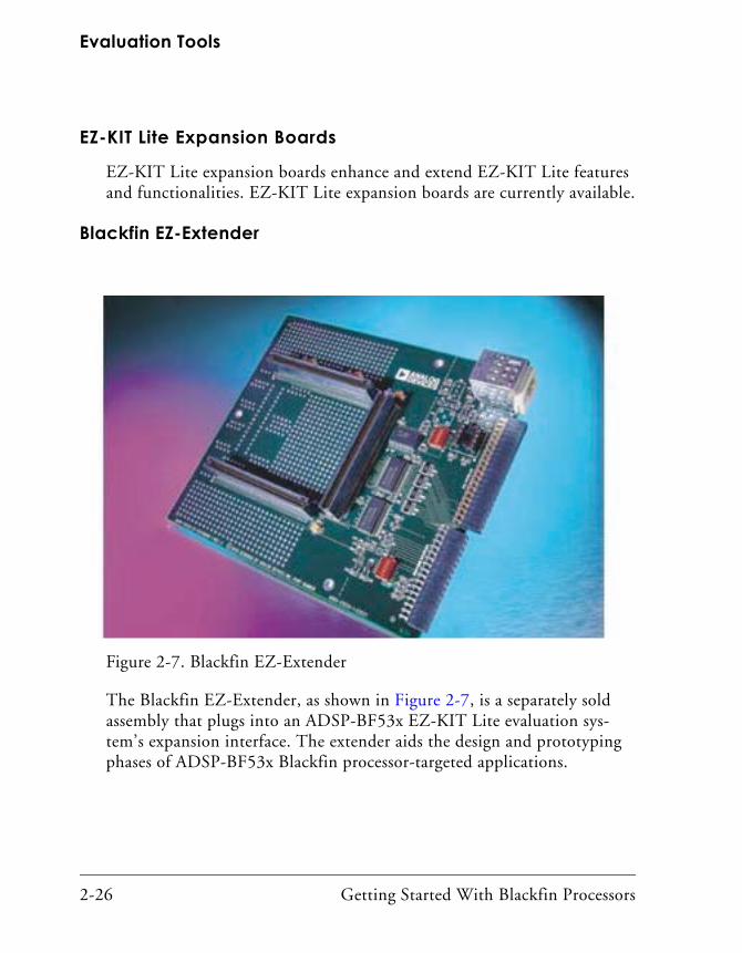
Evaluation Tools
2-26 Getting Started With Blackfin Processors
EZ-KIT Lite Expansion Boards
EZ-KIT Lite expansion boards enhance and extend EZ-KIT Lite features and functionalities. EZ-KIT Lite expansion boards are currently available.
Blackfin EZ-Extender
The Blackfin EZ-Extender, as shown in Figure 2-7, is a separately sold assembly that plugs into an ADSP-BF53x EZ-KIT Lite evaluation sys-tem’s expansion interface. The extender aids the design and prototyping phases of ADSP-BF53x Blackfin processor-targeted applications.
Figure 2-7. Blackfin EZ-Extender

Getting Started With Blackfin Processors 2-27
The Evaluation Process
The board extends the capabilities of the EZ-KIT Lite evaluation system by providing a connection between the Parallel Peripheral Interface (PPI) of the ADSP-BF53x EZ-KIT Lite board, an Analog Devices High Speed Converter (HSC) evaluation board, an OmniVision camera evaluation board, and an LCD display device. Moreover, the extender broadens the range of EZ-KIT Lite applications by providing surface-mounted (SMT) footprints for breadboard capabilities and access to all pins on the EZ-KIT Lite board’s expansion interface.
The Blackfin EZ-Extender features:
• OmniVision camera interface
• High Speed Converter (HSC) evaluation board interface
• LCD interface
• SMT footprint area

Evaluation Tools
2-28 Getting Started With Blackfin Processors
ADDS-USBLAN-EZEXT Card
The ADDS-USBLAN-EZEXT card, as shown in Figure 2-8, provides a solution for users to evaluate different peripherals on ADSP-BF533, ADSP-BF561, and ADSP-BF537 Blackfin processors.
The card includes peripherals that support USB 2.0 and Ethernet. The card also supports USB bus power. The components for bus power on the AV EZ-CONNECT1 card are not populated during shipping. For bus power to work, the AV EZ-CONNECT1 card must be connected to an EZ-KIT Lite evaluation system that also supports USB bus power. Currently, the ADSP-BF561 EZ-KIT Lite and the ADSP-BF533 EZ-KIT Lite do not support USB bus power.
Figure 2-8. ADDS-USBLAN-EZEXT Card

Getting Started With Blackfin Processors 2-29
The Evaluation Process
The AV EZ-CONNECT1 card is a small (approximately 4.5” x 3.5”) printed circuit board that connects directly to an EZ-KIT Lite board. The card includes the hardware, USB cable, USB software, and Ethernet soft-ware to begin evaluating the AV EZ-CONNECT1 immediately. Power is derived by plugging the card into the EZ-KIT Lite board.
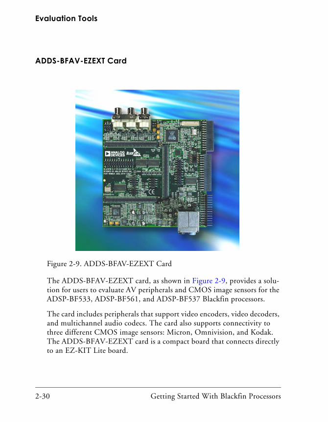
Evaluation Tools
2-30 Getting Started With Blackfin Processors
ADDS-BFAV-EZEXT Card
The ADDS-BFAV-EZEXT card, as shown in Figure 2-9, provides a solu-tion for users to evaluate AV peripherals and CMOS image sensors for the ADSP-BF533, ADSP-BF561, and ADSP-BF537 Blackfin processors.
The card includes peripherals that support video encoders, video decoders, and multichannel audio codecs. The card also supports connectivity to three different CMOS image sensors: Micron, Omnivision, and Kodak. The ADDS-BFAV-EZEXT card is a compact board that connects directly to an EZ-KIT Lite board.
Figure 2-9. ADDS-BFAV-EZEXT Card

Getting Started With Blackfin Processors 2-31
The Evaluation Process
ADSP-BF533 STAMP Board
The ADSP-BF533 STAMP µClinux kernel board support package pro-vides a cost-effective environment to develop embedded systems around ADSP-BF533 Blackfin processors. The STAMP board is specifically designed to support the development and porting of open source µClinux applications and includes the full complement of memory along with serial and network interfaces. A variety of available daughterboards plug into this board, adding interface functions such as audio, video, and ana-log input or output.
Besides an ADSP-BF533 500 MHz Blackfin processor, the board includes:
• 128 MB SDRAM (64M x 16 bits)
• 4 MB FLASH memory
• SMSC LAN91C111 Ethernet MAC/PHY
• RS-232 serial interface
• I/O connectors for these Blackfin peripherals: PPI, SPORT0 and SPORT1, SPI, timers, IRDA, and two-wire interface
• JTAG interface for debug and FLASH programming
• Three LEDs and three push buttons
Together with the ADSP-BF533 STAMP development board, the package includes a recent copy of the open source development tools (GCC 3.x) and the µClinux 2.6.x kernel. It also includes a CD with documentation and the board schematics, Gerbers, and layout files. The latest version of all the tools can be found on the http://blackfin.uclinux.org/ Web site. This Web site also hosts open source application projects based on the STAMP board and daughterboards (such as a networked audio media node), a networked oscilloscope, and a Blackfin XMAME game console.
Evaluation Tools
2-32 Getting Started With Blackfin Processors
JTAG Emulators
JTAG (Joint Test Action Group) is defined by the IEEE 1149.1 standard for a test access port for testing electronic devices. This standard defines a method for serially scanning the I/O status of each pin on the device as well as controlling internal operation of the device.
Boundary-scan testing was developed in the mid 1980s as the JTAG inter-face to solve physical access problems on PCBs caused by increasingly crowded assemblies due to novel packaging technologies. Boundary-scan embeds test circuitry at chip level to form a complete board-level test pro-tocol. With boundary-scan—industry standard IEEE 1149.1 since 1990—you can access the most complex assemblies for testing, debugging, in-system device programming, and diagnosing hardware problems.
Blackfin processors are equipped with a JTAG port and thus support the IEEE 1149.1 standard for system test.
Through the JTAG port, you can run and halt the processor remotely. The internal and external processor memory can be read or written, and breakpoints can be set.
Most development boards include some built-in JTAG emulation cir-cuitry. Your own hardware, most likely, does not contain this circuitry.

Getting Started With Blackfin Processors 2-33
The Evaluation Process
High Performance USB 2.0 JTAG Emulator
Part Number: ADDS-HPUSBAvailability: Now
The Analog Devices high speed, high performance, Universal Serial Bus-based emulator (HP-USB), as shown in Figure 2-10, provides a porta-ble, non-intrusive, target-based debugging solution for Analog Devices JTAG processors.
These easy to use USB-based emulators perform a wide range of emulation functions, including single step and full speed execution with predefined breakpoints, and viewing and/or altering of register and memory contents. With the ability to automatically detect and support multiple I/O volt-ages, the HP-USB emulator enables you to communicate with all of the Analog Devices JTAG processors using a full speed USB 1.0 or high speed USB 2.0 port on the host PC.
Applications and data can be tested and transferred easily (and rapidly, when the HP-USB emulator is connected to a high speed USB 2.0 port on your host PC) between the emulators and the separately available Visu-alDSP++ development and debugging environment.
Figure 2-10. High Performance USB 2.0 JTAG Emulator

Evaluation Tools
2-34 Getting Started With Blackfin Processors
The plug-and-play architecture of USB allows the emulators to be auto-matically detected and configured by the host operating system. It can also be connected to (and disconnected from) the host without opening the PC or turning off the power to the PC. A 3-meter (9-foot) cable is included to connect the emulators to the host PC, thus providing abundant accessibility.
As a bonus, customers in an environment that does not allow them to open their PCs without IS support will find that both emulators eliminate the need to obtain that help and thus can be easily moved from the lab to the local desktop to the laptop.
Features
• High speed USB 2.0 (backward compatible with full speed USB 1.0) interface and connector
• JTAG clock operation from 10 MHz to 50 MHz
• Support for all ADI JTAG processors
• Multiple processor I/O voltage support with automatic detection
• 1.8 V, 2.5 V, and 3.3 V compliant and tolerant
• 5 V tolerant and 3.3 V compliant for 5 V processors
• Multiprocessor support
• 14-pin JTAG connector
• 3-meter USB cable for difficult to reach targets
Analog Devices JTAG emulators are supported by VisualDSP++ only. The HP-USB Emulator is only supported by VisualDSP++ 3.5 (and later versions).

Getting Started With Blackfin Processors 2-35
The Evaluation Process
USB 1.1 JTAG Emulator
Part Number: ADDS-USB-ICEAvailability: Now
The cost-effective Universal Serial Bus (USB)-based emulator, as shown in Figure 2-11, from Analog Devices provides a portable, non-intrusive, tar-get-based debugging solution for Analog Devices JTAG processors.
This USB-based emulator performs a wide range of emulation functions, including single step and full speed execution with predefined break-points, and viewing and/or altering of register and memory contents. With the ability to automatically detect and support multiple I/O volt-ages, the USB emulator enables users to communicate with all of the Analog Devices JTAG processors using a full speed USB 1.0 or high speed USB 2.0 port on the host PC. Applications and data can easily be tested and transferred between the emulator and the separately available Visu-alDSP++ development and debugging environment.
Figure 2-11. USB 1.1 JTAG Emulator

Evaluation Tools
2-36 Getting Started With Blackfin Processors
The plug-and-play architecture of USB allows the emulators to be detected automatically and configured by the host operating system. The USB can also be connected to (and disconnected from) the host without opening the PC or turning off the power to the PC. A 3-meter (9-foot) cable is included to connect the emulators to the host PC, thus providing abundant accessibility.
As a bonus, customers in an environment that does not allow them to open their PCs without IS support will find that the USB emulator elimi-nates the need to obtain that help and thus can be easily moved from the lab to the local desktop to the laptop.
Features
• Full speed USB 1.1 compliant (forward compatible with high speed USB 2.0 interface and connector)
• Support for all ADI JTAG processors
• Multiple processor I/O voltage support with automatic detection
• 1.8 V, 2.5 V, and 3.3 V compliant and tolerant
• 5 V tolerant and 3.3 V compliant for 5 V processors
• Multiprocessor support
• 14-pin JTAG connector
• 3-meter USB cable for difficult to reach targets
Analog Devices JTAG emulators are supported by VisualDSP++ only. The USB 1.1 Emulator is only supported by VisualDSP++ 3.5 (and later versions).

Getting Started With Blackfin Processors 2-37
The Evaluation Process
High Performance PCI JTAG Emulator
Part Number: ADDS-HPPCI-ICEAvailability: Now
This new high performance (HP) PCI-based emulator, as shown in Figure 2-12, offers code download speeds of up to 2.2 MB/sec with the JTAG clocked five times faster than its predecessor. It can also seamlessly exchange real-time data from the host to target application. The PCI-based emulator provides a high speed emulation solution for Analog Devices state of the art JTAG processors.
This high performance PCI-based emulator consists of a small shielded POD and cable, allowing for a non-intrusive debug interface to all of the ADI JTAG processors. The emulator auto-detects voltages for 1.8 V, 2.5 V, 3.3 V, and 5.0 V targets as indicated by the display LEDs. The cable extends 6-feet from the host PC to the emulator POD, and extends 1-foot from the POD to the processor target. This new cable assembly greatly extends the reach of the emulator, helping to reduce clutter in the hardware lab.
Figure 2-12. High Performance PCI JTAG Emulator

Evaluation Tools
2-38 Getting Started With Blackfin Processors
Features
• Plug-and-play, PCI Revision 2.2 compliant
• Multiple emulator support
• Multiple processor I/O voltage support
• 1.8 V, 2.5 V, and 3.3 V compliant and tolerant
• 5 V tolerant and 3.3 V compliant for 5 V processors and DSPs
• Multiprocessor support
• JTAG clock operation up to 50 MHz
• 3-meter USB cable for difficult to reach targets
This emulator is supported by VisualDSP++ only.

Getting Started With Blackfin Processors 2-39
The Evaluation Process
Selecting the Right Combination of ToolsKnowing which tools to use is critical to ensuring a quick development cycle. There are many options for both software and hardware develop-ment tools. Two of the most common scenarios described in this section contain circumstances encountered by other developers along with recom-mended solutions. Your needs may be similar to one of the following scenarios.
Scenario 1
Question. We are a small design house with one software engineer and one hardware engineer for this project. We cannot afford a substantial initial investment in tools. What do you recommend?
Answer. Purchase an ADSP-BF533 EZ-KIT Lite evaluation system (p/n: ADDS-BF533-EZLITE).
This hardware platform allows you to begin software development. By interfacing components to the board’s expansion headers, the platform can serve as the basis for a hardware prototype. The EZ-KIT Lite evaluation system includes VisualDSP++, but the software license restricts various capabilities (debug agent connectivity only and reduced program size allowance).
Obtain a TestDrive serial number on the Analog Devices Web site at:
http://forms.analog.com/Form_Pages/processors/visualDSPTest-
Drive.asp.
When the TestDrive license expires, consider purchasing a full seat of VisualDSP++ (p/n: VDSP-BLKFN-PC-FULL).
After you have finished constructing your hardware, purchase a low cost USB emulator (p/n: ADDS-USB-ICE) from Analog Devices.

Evaluation Tools
2-40 Getting Started With Blackfin Processors
Scenario 2
Question. We have a team of seven software engineers who are developing code for the Blackfin processor, but no more than five are likely to be using the tools at any given time. How do we handle licensing? Does each engineer need a license?
Answer. A floating license may be right for you. VisualDSP++ may be installed on many machines. A developer checks out a floating license from a license server onto any machine. With five floating licenses, up to five people can use VisualDSP++ at the same time.
Order a floating license (p/n: VDSP-BLKFN-PCFLOAT).
Software Development on Blackfin ProcessorsOnce the development tools are installed, begin working with application software development. Figure 2-1 on page 2-2 shows a typical develop-ment flow.
Some users modify a development board in parallel with software applica-tion development. The modified board serves as a prototype until their own hardware is built and ready.
Eventually, your custom hardware becomes available and you then move development to that platform. This custom hardware will include a 13-pin header called a JTAG port that connects to the Blackfin processor. To debug this custom board, Analog Devices recommends that you purchase a JTAG emulator. Emulators enable you to perform the debug operations that you may have performed previously on a development board on your own custom hardware.
Getting Started With Blackfin Processors 3-1
3 SUPPORT OPTIONS
As new information, such as data sheets, manuals, online Help, training, Web content, or automatic e-mail notifications are prepared/revised, Ana-log Devices makes it available to its customers and other interested parties. This chapter addresses the support options available for users both during the evaluation process and after you have purchased a Blackfin processor.
This chapter consists of:
• “Available Support” on page 3-1This section lists the various types of support.
Available SupportThe Blackfin processor architecture provides many advanced features. As next-generation processors, these parts are becoming increasingly com-plex. With that in mind, Analog Devices provides a wide variety of support options, both in the form of printed and online information, as well as in training. This wealth of information is available to aid evaluators of software/hardware solutions (at the beginning of the evaluation pro-cess), design engineers (while they are developing a system), or support engineers as they resolve compatibility and usability issues (after product release).
This chapter highlights some support, information, and training options available to Analog Devices users at any stage of development.

Available Support
3-2 Getting Started With Blackfin Processors
Since information about our products changes and increases rapidly, Analog Devices makes this information readily available and encourages you to keep up to date with new developments, especially with our online options.
Analog Devices Web SiteYour first point of reference for the most recent information is always via the Analog Devices Web site. The following kinds of information are available:
• Processor and tools selection guides
• Getting started information
• Applications notes, EE-notes, and other articles
• Communities-related information
• Platform-related information
Visit the Blackfin processor home page at www.analog.com/blackfin. The Analog Devices Embedded Processing and DSP page, which offers access to other processor families, is located at www.analog.com/proces-sors. To visit the knowledge base, use your browser to access www.analog.com/dsp/knowledgebase. This information is available to all classes of users, Analog Devices customers, and interested parties.
Processor and Tools Selection Information
For processor-specific information start at the Web site’s Blackfin proces-sor page (www.analog.com/blackfin), and then check Blackfin processor offerings with regards to package, speed, or temperature specifications. Links provide access to additional processor selection information (such as peripherals and memory), tools selection information, and other materials.

Getting Started With Blackfin Processors 3-3
Support Options
Getting Started Information
The Blackfin processor page (www.analog.com/blackfin) provides links under the heading “Getting Started” that instruct you about Blackfin pro-cessor architecture and targeted applications. To find out about the processor’s core and peripherals, refer to this Web site topic at the Analog Devices Web site. You may also want to check the benchmark data avail-able from independent testers. A link to training and events provides an up to date list of local training seminars and upcoming events where you can learn more about current or new Blackfin processor products.
Applications Notes, EE-Notes, and Other Articles
The most useful documents available to users are the Application or EE- (Engineer-to-Engineer) Notes since they offer detailed technical informa-tion about using the Blackfin processor. These materials are available by downloading them from the Web site.
These documents supplement the standard documentation for processors and tools. EE-Notes focus on a very narrow or specific topic. Articles are grouped under the headings “Processor-Specific”, “Tools-Specific”, and “Application Hints”. Note that you can also use VisualDSP++ Help to search, locate, and view this collection of articles, as well as the entire list of all EE-Notes.
Additional links are provided to recent articles, many of which have been featured in trade magazines. Please point your browser to www.analog.com/ee-notes.
Communities-Related Information
For information about application-specific development types (communi-ties), refer to the “Communities” topic at the Blackfin processor Web site. Here you can find information about a particular application theme, such as automotive telematics or video/imaging.

Available Support
3-4 Getting Started With Blackfin Processors
Platforms-Related Information
When information about the Blackfin processor and its use with other hardware or software solutions becomes available, we refer to that as “Plat-form-Related Information.” Refer to the “Platform-Related” topic for this information.
Workshops and SeminarsThe most efficient way to learn about the Blackfin processor architecture is by attending a 3½-day (or 1-day) Blackfin seminar, which provides a mixture of lectures and demonstrations. The 3½-day workshop provides hands on exercises and serves as an excellent starting point for both hard-ware and software development.
However, a variety of training options are available, both online and in a classroom setting. For users who prefer live training sessions, a variety of venues is available.
Blackfin Processor Workshops
Blackfin processor workshops are designed to develop a strong working knowledge of Analog Devices processors through lecture and hands on exercises in a classroom setting.
These practical courses teach how to use the latest software development tools. First, the core elements of the processor, which includes the Com-putational Units, the Data Address Generators, and the Program Sequencer, are examined along with the relevant assembly code instruc-tions. A number of simulator labs help in understanding operation of the individual elements. Memory configuration (both internal and external) is discussed next. Advanced instructions are presented with a follow on lab session about code optimization. The I/O peripherals, which include the SPORTS, Link Ports, and External Port, are discussed in detail along with DMA operation between these peripherals and internal memory.

Getting Started With Blackfin Processors 3-5
Support Options
Workshops are offered through Kaztek Engineering throughout the world. Visit the Kaztek Web site for the schedule of upcoming workshops and pricing information at:
http://www.kaztek.com/.
Blackfin Processor Seminars
The Blackfin processor seminar is a subset of the Blackfin Processor Workshop slide set and does not include hands on exercises. A Blackfin seminar is often accompanied by tools and software demonstrations run-ning on hardware (sometimes by key Analog Devices third party partners).
Contact your local Analog Devices sales office or distribution partner for information on Blackfin seminars or refer to:
www.analog.com/processors/training/index.html.
TechOnLine Seminars
If you cannot attend a workshop or seminar, check the archive of online Blackfin seminars that Analog Devices offers at www.analog.com/proces-sors/training/workshops/onlinetraining.html. While these online seminars tend to be much shorter than others, they offer solid overviews of key software and hardware design topics.
To access these seminars go to http://www.techonline.com. Click the “On-Demand Webcasts” link, then search on Blackfin.
You can also request a copy of the Blackfin seminar and/or workshop material from Analog Devices. This includes all of the slides, associated notes, and exercises. Contact your local Analog Devices sales office for more information.

Available Support
3-6 Getting Started With Blackfin Processors
µClinux on the Blackfin Processor 3-Day Workshop
This course is an introduction to all aspects of programming with µClinux based on the Blackfin processor STAMP board. The course is presented by System Design and Consulting Services in various locations.
The course covers the following subjects: development tools, compiler, linker, Blackfin processor assembler and debugger, bootloader (U-boot), µClinux source distribution, µClinux libraries, Linux boot-up, Linux kernel 2.6.x, FLASH memory and FLASH file systems, introduction to device drivers, µClinux debugging, network applications, and example user applications. For further information, go to:
http://www.analog.com/processors/training/workshops
/uClinuxws.html.
Processor DocumentationThree documents accompany each Blackfin processor: a data sheet, a hardware reference, and an instruction set (or programming) reference. These documents enable you to design software and hardware.
Blackfin Processor Manuals
Two kinds of manuals provide detailed information about the Blackfin processor: the Hardware Reference Manual and the Instruction Set Reference.
Hardware Reference Manuals
Each processor’s hardware reference manual provides architectural infor-mation about that particular Blackfin processor. The descriptions cover functional blocks, buses, and ports, including all features and processes that they support.

Getting Started With Blackfin Processors 3-7
Support Options
Typically, a hardware reference (HRM) manual is available for each sub-family of processors. For example, Analog Devices provides one manual for the ADSP-BF535 processor, another for ADSP-BF531/532/533 devices (entitled ADSP-BF535 Blackfin Processor Hardware Reference), another for the ADSP-BF561 processor, and another for ADSP-BF537/536/534 devices (entitled ADSP-BF537 Blackfin Processor Hardware Reference). Each subsequent subfamily of Blackfin processors will have a unique manual to describe its particular architecture and peripherals.
Before a processor is released to production, its hardware reference manual is available only in electronic form as a .PDF file. After it is released, the manual is available in both electronic form and as a printed manual. The VisualDSP++ Help system also includes a copy of each hardware reference manual and provides powerful search facilities to help you locate information.
You can find Blackfin processor hardware reference manuals at:
http://www.analog.com/Processors/Processors/blackfin/technicalL-
ibrary/manuals/blackfinIndex.html#Processor%20Manuals.
Instruction Set Reference
The instruction set reference contains information about the processor architecture and assembly language for Blackfin processors. The manual provides information on how assembly instructions execute on the Black-fin processor’s architecture, along with reference information about processor operations.
If you intend to program in C only, this document is of no value to you. However, if you intend to author some assembly code, obtain this book.
Before a processor is released to production, its instruction set reference (ISR) is available only in electronic form as a .PDF file. After it is released, the manual is available in both electronic form and as a printed manuals.

Available Support
3-8 Getting Started With Blackfin Processors
The VisualDSP++ Help system also includes a searchable version of the instruction set reference so you can locate information quickly.
Starting in mid-2005, the processor core and instruction set, which is common to all Blackfin processors, will be documented in a programming reference manual (PRM). This new manual will take the place of the Blackfin Processor Instruction Set Reference. Hardware reference manuals will continue to describe the peripherals unique to that processor’s subfamily.
You can find the Blackfin processor instruction set reference at:
http://www.analog.com/Processors/Processors/blackfin/technicalL-
ibrary/manuals/blackfinIndex.html#Processor%20Manuals.
Printed Manuals
Printed copies of processor manuals, such as hardware reference, instruc-tion set reference, and programming reference manuals, may be ordered from the Analog Devices Literature Center at 800-ANALOGD (800-262-5643). When ordering hard copy documentation, specify the manual’s title or product number (located on the manual’s back cover).
Downloadable Manuals
While users may want printed versions of manuals, PDF versions of these manuals are also readily available. These may be downloaded from the Analog Devices Web site. Open your browser and access:
www.analog.com/processors/resources/technicalLibrary/manuals/.
Documentation Errata
Documentation errata for manuals is listed on the Analog Devices Web site with the actual manual to which it pertains. If you are looking for document errata for a manual (hardware reference, instruction set

Getting Started With Blackfin Processors 3-9
Support Options
reference, and so on), the errata is posted as if it is another chapter in the manual at:
http://www.analog.com/Processors/Processors/blackfin/technicalL-
ibrary/manuals/blackfinIndex.html
Data Sheets
Data sheets are created for each Blackfin processor and for each release of a single product. Each Blackfin processor data sheet provides:
• A high level overview of the processor
• A description of processor pins
• Electrical, power, and timing characteristics/requirements
• Device package dimensions
• Environmental (temperature) information
To obtain data sheets for Blackfin processors, open your browser and access:
http://www.analog.com/processors/processors/blackfin
/dataSheets.html.
Anomalies Lists for Processors and Tools
Analog Devices maintains an anomalies list for each subfamily of Blackfin processors and also maintains an anomalies list for tools. These lists are updated as new information becomes available.
Processor anomalies represent the currently known differences between revisions of Blackfin devices and the functionality specified in the Blackfin processor data sheets and hardware manuals. A revision number with the form “-x.x” is branded on all parts to identify them according to silicon revisions.
Available Support
3-10 Getting Started With Blackfin Processors
For processor anomalies, refer to:
http://www.analog.com/processors/technicalSupport/hardwareAnoma-
lies.html.
For tools anomalies, refer to:
http://www.analog.com/processors/technicalSupport/toolsAnoma-
lies.html,
BSDL Files
Boundary Scan Description Language (BSDL) files are necessary for the application of boundary-scan for board and system-level testing and in-system programming. BSDL files are the electronic data sheets that describe the IEEE 1149.1 or JTAG design within an IC, and are provided by the IC vendors as part of their device specifications. Use BSDL files to describe the test logic and generate a test for a loaded board.
IBIS Models
I/O Buffer Information Specification (IBIS) models are used with various IBIS-based simulators for transmission line simulation of digital systems. These models accurately simulate I/O buffers, termination, and circuit board traces. The simulation time is much faster than SPICE simulations, because it is a behavioral model that relies on tabulated current versus voltage characteristics. For more information about IBIS models, see the main ANSI/EIA IBIS home page at:
http://www.eigroup.org/IBIS.
CrossCore Tools DocumentationDocumentation in both electronic form and printed form describe the various components of the CrossCore® software and hardware tools.

Getting Started With Blackfin Processors 3-11
Support Options
Analog Devices offers a software tools environment (VisualDSP++) and an assortment of hardware development tools.
For software tools, each release of VisualDSP++ includes a complete set of manuals, describing the entire software development tool chain. Printed copies of VisualDSP++ software tools manuals (compiler, assembler, and so on) ship with the software. You can purchase additional sets through Analog Devices Customer Service (781-329-4700). For additional infor-mation, call 603-883-2430. If you do not have an account with Analog Devices, you will be referred to an Analog Devices distributor.
Printed copies of software tools manuals are not provided with “TestDrive” licences.
“Hardware Tools Documentation” on page 3-15 describes EZ-KIT Lite evaluation systems, emulators, and extender boards. Printed copies of hardware tools manuals are packaged with the hardware.
To access the VisualDSP++ Tools Anomalies search page, point your browser at:
http://www.analog.com/processors/cda/epTASearch/.
VisualDSP++ Documentation
This section briefly describes the VisualDSP++ manual set. The purchase of a full license of VisualDSP++ includes a printed copy of each manual. Electronic versions of documents are available from the VisualDSP++ installation CD-ROM or via download from the following Web page:
http://www.analog.com/Processors/Processors/blackfin/technicalLibrary/manuals/blackfinIndex.html#Software%20Manuals.
VisualDSP++ Help incorporates a searchable version of the VisualDSP++ manual set plus processor documentation and other tools manuals. See “VisualDSP++ Help” on page 3-18 for details.
Available Support
3-12 Getting Started With Blackfin Processors
VisualDSP++ Getting Started Guide
This manual provides step by step, 15-minute tutorials that highlight VisualDSP++ features. By completing the tutorials, users can become familiar with the VisualDSP++ environment quickly, and see how easy it is to use several tools in your own digital signal processing (DSP) develop-ment projects.
This manual and accompanying software provide an excellent starting point to gain a high level of understanding of the VisualDSP++ suite of project management and application development tools.
VisualDSP++ User’s Guide
This manual describes the features, components, and functions of the VisualDSP++ integrated development and debugging environment (IDDE). It covers license management, project management, code devel-opment, debugging tools, VDK, and much more.
Use this high level reference to delve further into the powerful features of VisualDSP++. In addition to describing the user interface’s main window and debugging windows, this manual also describes simulation and tools that allow you to view the Blackfin processor’s pipeline.
VisualDSP++ C/C++ Compiler and Library Manual for Blackfin Processors
This manual contains information about the C/C++ compiler and runtime libraries for Blackfin processors.
The manual provides information on compiler options, language exten-sions, and C/C++/assembly interfacing, and shows how to optimize compiler operation. It explains how to use library functions and provides a complete C/C++ library function reference.

Getting Started With Blackfin Processors 3-13
Support Options
The manual describes the DSP runtime library which contains a broad collection of functions commonly required by signal processing applica-tions. The services provided by the DSP runtime library include support for general-purpose signal processing such as companders, filters, and Fast Fourier Transform (FFT) functions. All these services are Analog Devices extensions to ANSI standard C. These functions are in addition to the C/C++ runtime library functions.
The manual describes the ADSP-BF561 Blackfin processor architecture (as compared to the ADSP-BF533 Blackfin processor) and then describes two approaches to application development using VisualDSP++ and offers guidelines for developing systems on the ADSP-BF561 Blackfin processor.
VisualDSP++ Assembler and Preprocessor Manual
This manual focuses on assembly programming for Blackfin processors that support a Media Instruction Set Computing (MISC) architecture.
The manual provides how-to information for writing assembly programs for Blackfin processors and reference information about related develop-ment software. It also provides information on new and legacy syntax for assembler and preprocessor directives and comments, as well as com-mand-line switches.
VisualDSP++ Linker and Utilities Manual
This manual provides information on the linking process and describes the syntax for the linker’s command language—a scripting language that the linker reads from the Linker Description File (.LDF). The manual leads you through using the linker, archiver, and loader to produce proces-sor programs. It also provides reference information on file utility software.
The manual also describes how overlays and advanced LDF commands are used for memory management. In addition, it describes the Expert Linker, an interactive graphical tool to set up and map processor memory.

Available Support
3-14 Getting Started With Blackfin Processors
VisualDSP++ Kernel (VDK) User’s Guide
This manual contains information about the VisualDSP++ Kernel, a real-time operating system kernel integrated with the VisualDSP++ development tools. The VDK incorporates state of the art scheduling and resource allocation techniques tailored specifically for the memory and timing constraints of DSP programming. Using frameworks of template files, the kernel facilitates development of performance-structured applications. The kernel is designed for effective operations on Analog Devices processors.
The majority of the information in this manual is generic. Information applicable to a particular target processor, or to a particular processor family, is provided in Appendix A, “Processor-Specific Notes.” This man-ual explains the kernel internal structure and operation.
VisualDSP++ Loader Manual
This manual contains information on how to use the loader/splitter to convert executable files into boot-loadable (or non-bootable) files. These files are then programmed/burned into an external memory device within your target system.
The manual begins by examining where loading/splitting fits in the typical program development activities. It discusses boot modes, boot streams, and second stage kernels. This manual contains the details you need to know about booting each particular subfamily of Blackfin processors.
Device Driver and System Service Libraries Manual
This manual describes device drivers and system services. Included is an overview and detailed description of the device driver model. It covers the device driver API and the various data flow methods that devices use to transfer data into and out of the processor. Included are examples of both DMA-driven and interrupt-driven drivers, and tutorials that show how to quickly write efficient device drivers that comply with the model.

Getting Started With Blackfin Processors 3-15
Support Options
Also included in this manual are the details of powerful system services that are available to applications through the System Services Library. This manual describes how applications can use the System Services Library to control the Blackfin processor’s dynamic power management capabilities, control external asynchronous and synchronous memories, and manage interrupt processing. The manual also describes how applica-tions can utilize the services of the DMA and callback to easily schedule both peripheral and memory DMA transfers, and defer non-critical event-driven processing to a lower priority. Details on the APIs for the system services are provided as well as examples that demonstrate how applications can leverage these services.
Hardware Tools Documentation
Each hardware tool (EZ-KIT Lite evaluation system, emulator, AV extender card, EZ-CONNECT1 card, or STAMP board) available from Analog Devices includes electronic and printed documentation. Typically this documentation includes schematics, a short description of switch and jumper settings, and a bill of materials. Printed documentation accompa-nies the purchase of hardware. Download electronic versions of the documentation (.PDF format) from the following Web page:
http://www.analog.com/Processors/Processors/blackfin/technicalL-
ibrary/manuals/blackfinIndex.html#Evaluation%20Kit%20Manuals.
Getting Started With the ADSP-BF5357 EZ-KIT Lite
This manual provides exercises for the ADSP-BF537 Blackfin processor while working within the VisualDSP++ development system. In half a day, you can:
• Connect the EZ-KIT Lite to your PC and write your first program
• Measure the performance and the impact of memory hierarchy and voltage on performance

Available Support
3-16 Getting Started With Blackfin Processors
• Use the TCP/IP peripheral of the ADSP-BF537 Blackfin processor
• Connect to your network and build the LwIP stack tailored to your application
• Create a Caesar Cipher application using VDK and LwIP
• Connect to the application with telnet
• Create an audio talk-through application with TCP/IP
• Change the audio and control volume via telnet
• Change clock frequency via telnet
ADSP-BF535 EZ-KIT Lite Evaluation System Manual
This manual provides instructions for using the hardware and installing the software on your PC. This manual also provides guidelines for run-ning your own code on the ADSP-BF535 EZ-KIT Lite. In addition, the manual describes the operation and configuration of the evaluation board’s components. Finally, a schematic and a bill of materials are pro-vided as a reference for future ADSP-BF535 Blackfin processor board designs.
This manual provides information on the EZ-KIT Lite from a program-mer’s perspective and provides an easy to access memory map of the board.
ADSP-BF533 EZ-KIT Lite Evaluation System Manual
This manual provides instructions for using the hardware and installing the software on your PC. This manual also provides guidelines for run-ning your own code on the ADSP-BF533 EZ-KIT Lite. In addition, the manual describes the operation and configuration of the evaluation board’s components. Finally, a schematic and a bill of materials are pro-vided as a reference for future ADSP-BF533 Blackfin processor board designs.

Getting Started With Blackfin Processors 3-17
Support Options
This manual provides information on the EZ-KIT Lite from a program-mer’s perspective and provides a memory map of the board.
ADSP-BF537 EZ-KIT Lite Evaluation System Manual
This manual provides instructions for using the hardware and installing the software on your PC. This manual also provides guidelines for run-ning your own code on the ADSP-BF537 EZ-KIT Lite. In addition, the manual describes the operation and configuration of the evaluation board’s components. Finally, a schematic and a bill of materials are pro-vided as a reference for future ADSP-BF537 Blackfin processor board designs.
This manual provides information on the EZ-KIT Lite from a program-mer’s perspective and provides a memory map of the board.
ADSP-BF561 EZ-KIT Lite Evaluation System Manual
This manual provides instructions for using the hardware and installing the software on your PC. This manual also provides guidelines for run-ning your own code on the ADSP-BF561 EZ-KIT Lite board. In addition, the manual describes the operation and configuration of the evaluation board’s components. Finally, a schematic and a bill of materials are pro-vided as a reference for future ADSP-BF561 Blackfin processor designs.
This manual provides information on the EZ-KIT Lite from a program-mer’s perspective and provides a memory map of the board.
Blackfin EZ-Extender Manual
This manual provides example programs to demonstrate the capabilities of the ADSP-BF53x EZ-Extender board. The extender features:
• OmniVision camera interface
• High Speed Converter (HSC) evaluation board interface

Available Support
3-18 Getting Started With Blackfin Processors
• LCD interface
• SMT footprint area
VisualDSP++ Help
VisualDSP++ online Help is a powerful search tool. It combines the following documents and much more in one place:
• Complete VisualDSP++ manual set
• Processor hardware manuals and hardware tools manuals
• Over 200 hundred technical articles (EE-Notes)
The Help system is integrated into VisualDSP++’s graphical user interface and also provides context information (for debugging windows, tools, and dialog boxes). Each task is described in clear step by step detail.
Best of all, VisualDSP++ Help provides a single access point to just about every processor hardware and tools document produced by Analog Devices, Inc.
The search engine in Help enables you to find information quickly from a two foot deep stack of printed manuals, spanning over 10,000 pages.
VisualDSP++ Help, built around the familiar Microsoft HTML Help standard, enables you to:
• Copy code examples from Help into your source documents
• Bookmark and print topics
• Perform a full text search, or refine a search with wildcards, nested expressions, or Boolean operators

Getting Started With Blackfin Processors 3-19
Support Options
The DSP CollaborativeThe DSP Collaborative™ is a network of processor/DSP third party developers for Analog Devices. The DSP Collaborative consists of compa-nies all over the world that provide hardware products, software products, algorithms, and design services for a wide variety of applications and mar-kets. Our partners offer consulting services as well as commercial off the shelf products specifically for parts from Analog Devices. To learn more, go to:
http://dspcollaborative.analog.com/developers/DSP_LearnMore.html
Technical or Customer SupportAccess Analog Devices, Inc. Customer Support in the following ways:
• Visit the Embedded Processing and DSP Products Web site athttp://www.analog.com/processors/technicalSupport
• E-mail tools questions [email protected]
• E-mail processor questions [email protected] (Worldwide support)
[email protected] (Europe support)
[email protected] (China support)
• Phone questions to 1-800-ANALOGD
• Contact your Analog Devices Inc., local sales office or authorized distributor

Available Support
3-20 Getting Started With Blackfin Processors
• Send questions by mail to:Analog Devices, Inc.
One Technology Way
P.O. Box 9106
Norwood, MA 02062-9106
USA
MyAnalog.comMyAnalog.com is a free feature of the Analog Devices Web site that allows customization of a Web page to display only the latest information on products you are interested in. You can also choose to receive weekly e-mail notifications, containing updates to the Web pages that meet your interests. MyAnalog.com provides access to books, application notes, data sheets, code examples, and more.
Be sure to enable the weekly automatic notification feature. These mail-ings are especially important as they notify you of processor anomalies and errata.
Registration
Visit www.myanalog.com to sign up. Click Register to use MyAnalog.com. Registration takes about five minutes and serves as a means to select the information you want to receive.
If you are already a registered user, just log on. Your user name is your e-mail address.

Getting Started With Blackfin Processors I-1
I INDEX
AADSP-BF533
EZ-KIT Lite evaluation system, 2-17, 3-16, 3-17
STAMP uClinux kernel board, 2-31ADSP-BF535
EZ-KIT Lite evaluation system, 2-20, 2-24, 3-15, 3-16
ADSP-BF561application development, 3-13EZ-KIT Lite evaluation system, 2-22,
3-17algorithms, 1-23anomalies lists, 3-9application development
ADSP-BF561, 3-13stages of, 2-3typical flow, 2-40
application notes, 3-3applications
control, 1-4signal processing, 1-4
assembler, 2-9, 3-13assembly coding, 1-5assembly language, 3-7audio algorithms, 1-23Automation API, 2-7AV EZ-CONNECT card, 2-28
Bbackground telemetry channels, 2-8BDTI, 1-15benchmarks
BDTI, 1-15EEMBC, 1-20processor algorithms, 1-23URL showing Blackfin performance,
1-22Berkeley Design Technology Incorporated
(BDTI), 1-15Blackfin
application development, 2-3, 2-40architecture, 1-2, 1-10core, 1-10data sheets, 3-9dual-core devices, 1-6EZ-Extender, 3-17interfaces, 1-10optimization, 1-5power management, 1-13scalability, 1-12selection information, 3-2specifications, 1-8, 3-9speed, 1-11training, 3-4uClinux support, 2-14
Blackfin EZ-Extender, 2-26, 3-17BSDL files, 3-10BTC, 2-8
INDEX
I-2 Getting Started With Blackfin Processors
Ccache memory controller support, 1-4cache visualization, 2-9C/C++ compiler, 2-9, 3-12code density
Blackfin benefit, 1-5comparative graphic, 1-21compiler, 1-24
code examplesAnalog Devices benchmarks, 1-23EZ-KIT Lite, 1-23
compiled simulation, 2-9compiler
C/C++, 2-9code density, 1-24compiled simulation, 2-9Green Hills Software, 2-11manual, 3-12program-guided optimization, 2-8
convolution, 1-23courses, 3-4CrossCore tools, documentation, 3-11customer support, 3-19
Ddata sheets, 3-9debugging tools, 2-6device drivers, 1-24discrete cosine functions, 1-23documentation
hardware tools, 3-15processor, 3-6VisualDSP++, 3-11
DSP, See processorsDSP Collaborative, 3-19dual-core processors, 1-6, 1-13
EEE-Notes, 3-3email notifications, 3-20Embedded Microprocessor Benchmark
Consortium (EEMBC), 1-20emulators, 2-32encoding, 1-23evaluation system, See EZ-KIT Lite
evaluation systemsexception handling, 1-4expansion boards, 2-26Expert Linker, 2-10extenders, 3-17EZ-KIT Lite evaluation systems
defined, 2-15expansion boards, 2-26licensing, 2-15programs for, 1-23
Ffilters, 1-23Fourier cosine functions, 1-23frameworks, VDK, 2-7
GGCC tool chain, 2-4, 2-11GNU tool chain, 2-11graphing tools, 2-8Green Hills Software, Inc., tools, 2-10
Hhardware reference manuals, 3-6hardware tools
documentation, 3-15selecting, 2-15
Help (online), 3-18

Getting Started With Blackfin Processors I-3
INDEX
High-Performance PCI JTAG Emulator (HPPCI), 2-37
High-Performance USB 2.0 JTAG Emulator (HPUSB), 2-33
IIBIS models, 3-10image processing and analysis, 1-23instruction set reference, 3-7interfaces to the Blackfin processor, 1-10interrupt processing, 1-4, 1-5
JJPEG, 1-23JTAG emulators, 2-32
Kkernels, 2-7, 2-13
Llicenses
described, 2-15floating, 2-40
linking, 2-10, 3-13loader, 3-14
Mmanuals, See documentationMCU operation, 1-4memory management, 1-2, 1-3Micro Signal Architecture (MSA), 1-2multiprocessor support, 2-7multi-rate filters, 1-23MULTI tool (Green Hills Software, Inc.),
2-10MyAnalog.com, 3-20
Oonline Help, 3-18operating systems support, 1-2, 1-5
Pperformance, 1-11PGO, 2-8pipeline viewer, 2-9plotting tools, 2-8power management, 1-13processors
algorithms, 1-23anomalies lists, 3-9data sheets, 3-9functionality, 1-2programming, 1-4selection charts, 3-2
profile-guided optimization, 2-8profiling, statistical, 2-8projects
development stages, 2-1protected memory, 1-5protected mode, 1-3
Rreal-time operating systems (RTOS), 2-12RISC
instruction set, 1-2processing, 1-11
RTOS, deciding whether to use, 2-12
SSCC, See source code controlscripting, 2-7seminars, 3-4signal processing, 1-4

INDEX
I-4 Getting Started With Blackfin Processors
simulationcompiled, 2-9pipeline viewer, 3-12
software development tools, 2-4, 2-12software licenses, 2-15source code control (SCC), 2-10specifications
data sheets, 3-9key features, 1-8
speech algorithms, 1-23STAMP board, 2-31standard libraries, VDK, 2-7statistical profiling, 2-8system services, 1-24
Ttechnical support, 3-19TechOnLine seminars, 3-5tools
anomalies list, 3-9cache visualization, 2-9comparison of, 2-12CrossCore, 3-11debugging, 2-6GCC, 2-11Green Hills Software, Inc., 2-10hardware development, 2-15linking, 2-10pipeline viewer, 2-9plotting, 2-8profile-guided optimization, 2-8project management, 2-6selecting, 2-39software development, 2-4statistical profiling, 2-8
trade magazine articles, 3-3training, 3-4
UuClinux, 2-14, 2-31, 3-6USB 1.1 JTAG Emulator, 2-35
VVDK
defined, 2-7, 3-14versus a third party RTOS, 2-13
video processing, 1-2VisualDSP++
documentation, 3-11features, 2-4Help, 3-18kernel (VDK), 2-7project development, 2-1
Wworkshops, 3-4