getting started with mosaic - tecnolab · getting started with mosaic 1. introduction the mosaic...
TRANSCRIPT
Contents
GETTING STARTED WITH MOSAIC
7th edition - June 2009
Copyright © 2001-2009 Teco a.s.
Contents
1. INTRODUCTION..............................................................................................................101.1 Program supply..........................................................................................................101.2 Programming the PLC TECOMAT, TECOREG, IEC 61131-3..................................10
2. CREATING A NEW PROJECT.......................................................................................122.1 Running the Mosaic program....................................................................................122.2 Dialog for opening project groups..............................................................................13
3. BASIC DESCRIPTION OF THE MOSAIC ENVIRONMENT..........................................183.1 Mosaic environment work panels..............................................................................183.2 Docking windows.......................................................................................................193.3 Numbering docked windows......................................................................................193.4 Mosaic environment main menu ...............................................................................20
3.4.1 Description of icons in main menu ...................................................................203.4.2 Information about PLC state in main menu toolbar............................................213.4.3 Signalizing the selected communication type between PC and PLC................21
4. OVERVIEW OF MOSAIC TOOLS...................................................................................22
5. PROJECT MANAGER....................................................................................................265.1 Setting the address and type of connection to the PLC............................................275.2 Common settings.......................................................................................................285.3 HW configurator.........................................................................................................29
5.3.1 PLC series selecting...........................................................................................295.3.2 HW configuration................................................................................................30
5.3.2.1 Setting CHx communication channels on central unit..................................305.3.2.2 Setting the parameters of peripheral modules..............................................31
5.3.3 PLC network- logic connection...........................................................................32
1 TXV 003 20
Getting started with Mosaic
5.4 SW configurator.........................................................................................................345.4.1 Application program and library information window.........................................345.4.2 Window for setting PLC central units.................................................................355.4.3 Compiler settings window...................................................................................36
5.5 Environment configurator..........................................................................................375.5.1 PLC control window............................................................................................375.5.2 Other environment configuration windows ........................................................38
5.6 Documentation windows............................................................................................38
6. SETTING INPUTS AND OUTPUTS................................................................................396.1 Alias – naming input and output signals ...................................................................406.2 Map of I/O occupation and I/O absolute addresses .................................................41
7. IEC MANAGER................................................................................................................437.1 Local menu in IEC manager window.........................................................................437.2 POU rules..................................................................................................................447.3 Globally available variables.......................................................................................477.4 Organization of tasks and items – program configuration.........................................477.5 Libraries.....................................................................................................................48
8. TEXT EDITORS...............................................................................................................508.1 Structured text program.............................................................................................50
8.1.1 ST language program example..........................................................................518.1.2 Local menu in ST text editor window.................................................................528.1.3 Aids making programming easier ......................................................................53
8.1.3.1 IEC assistant (hotkey Ctrl+J) .......................................................................538.1.3.2 Definition of a IEC variable (hotkey Ctrl+D) .................................................548.1.3.3 Inserting a IEC variable into the text (hotkey Shift+Ctrl+V)..........................568.1.3.4 IEC code support (hotkey Ctrl+Space).........................................................56
8.2 Program in instruction list language..........................................................................578.2.1 Program example in IL.......................................................................................58
8.3 Text editor of general Txt texts..................................................................................588.4 xPro native code text editor ......................................................................................59
9. GRAPHIC EDITORS.......................................................................................................609.1 LD editor (Ladder Diagram).......................................................................................60
9.1.1 LD editor controls...............................................................................................619.1.2 Editing contact name - operand.........................................................................63
2 TXV 003 20
Contents
9.1.3 Inserting or editing a box in LD..........................................................................639.1.4 Inserting and editing operands at inputs/outputs in parameter boxes...............659.1.5 Local menu in LD editor desktop........................................................................669.1.6 Hotkeys in LD editor area...................................................................................66
9.2 FBD editor (Function Block Diagram)........................................................................679.2.1 FBD editor controls.............................................................................................689.2.2 Operand editing..................................................................................................709.2.3 Inserting or editing a box in FBD........................................................................709.2.4 Local menu within FBD editor desktop...............................................................729.2.5 Hotkeys in FBD editor area................................................................................73
9.3 SFC editor (in preparation) (Sequential Function Chart)...........................................739.4 Editor CFC (in preparation) (Continuous Flow Chart)...............................................73
10. OTHER TOOLS FOR AUTOMATIC PROGRAM CODE GENERATING.....................7410.1 PIDMaker ................................................................................................................7410.2 PanelMaker..............................................................................................................74
11. TOOLS FOR MANAGING PROJECTS........................................................................7611.1 Project groups..........................................................................................................7611.2 Files in a project.......................................................................................................7711.3 Open files ................................................................................................................77
12. PROGRAM COMPILATION..........................................................................................7912.1 Compilation of program in project............................................................................7912.2 ON-LINE programming............................................................................................8012.3 Generating a library from a project..........................................................................8012.4 Library dependency.................................................................................................81
13. PROGRAM DEBUGGING ............................................................................................8313.1 POU inspector in ST language................................................................................8313.2 POU inspector in IL language..................................................................................8413.3 POU inspector in LD language................................................................................8413.4 POU inspector in FBD language.............................................................................8513.5 Debugging in mnemocode language.......................................................................85
14. OTHER TOOLS FOR DEBUGGING AND SIMULATING.............................................8614.1 WebMaker ..............................................................................................................8614.2 GraphMaker ............................................................................................................8614.3 HMI text panel simulator .........................................................................................87
3 TXV 003 20
Getting started with Mosaic
14.4 Panel (semi graphics) .............................................................................................8814.5 Map of user registers ..............................................................................................8814.6 Windows of the bottom docking panel.....................................................................89
14.6.1 Message 1 and Message 2 windows...............................................................8914.6.2 Symbols window...............................................................................................8914.6.3 List of breakpoints window...............................................................................9014.6.4 Data window.....................................................................................................90
14.7 Accumulator and memory windows ........................................................................91 Accumulator window ..................................................................................................91 Memory 1 and Memory 2 panels ...............................................................................92
15. WORKING WITH PROJECTS AND PROJECT GROUPS ..........................................9315.1 Creating a new project group..................................................................................9315.2 Project group copying..............................................................................................9315.3 Adding a new project...............................................................................................9315.4 Adding another project ...........................................................................................9415.5 Project copying........................................................................................................94
16. ARCHIVING...................................................................................................................9516.1 Archiving project groups..........................................................................................9516.2 Archiving data from PLC..........................................................................................95
16.2.1 Archiving data from PLC DataBoxes................................................................9516.2.2 Archiving registers from PLC notebook memories...........................................95
17. Documentation printing..............................................................................................96
18. APPENDIXES ...............................................................................................................9718.1 Hotkeys....................................................................................................................97
4 TXV 003 20
Contents
LIST OF FIGURES
Fig. 1.Running the Mosaic development environment..................................................13
Fig. 2.Dialog window – Selecting a project group..........................................................13
Fig. 1.Dialog window – Creating a project group...........................................................14
Fig. 2.Dialog window – New project.................................................................................14
Fig. 3.Dialog window – Basic selection of control system............................................15
Fig. 4.Dialog window – Declaration of POU....................................................................15
Fig. 5.Dialog window – Definition of program instance.................................................16
Fig. 6.Example of empty program in the ST language...................................................17
Fig. 7.Example of empty program in the LD language...................................................17
Fig. 8.Mosaic panel layout................................................................................................18
Fig. 9.Docked local menu and floating window..............................................................19
Fig. 10.Main menu of Mosaic and main toolbar with icons...........................................20
Fig. 11.Examples of PLC state signalization...................................................................21
Fig. 12.Location of Project Manager icon in basic Mosaic window.............................26
Fig. 13.Project manager window......................................................................................26
Fig. 14.Setting the connection to the PLC.......................................................................27
Fig. 15.Setting the serial channel parameters................................................................27
Fig. 16.Setting the USB connection parameters ...........................................................27
Fig. 17.Simulated PLC.......................................................................................................28
Fig. 18.Program module manager....................................................................................28
Fig. 19.Folder settings.......................................................................................................28
Fig. 20.PLC series selection.............................................................................................29
5 TXV 003 20
Getting started with Mosaic
Fig. 21.Example of HW PLC Foxtrot configuration........................................................30
Fig. 22.Example of HW PLC TC700 configuration..........................................................30
Fig. 23.Setting the universal channel mode to an Ethernet interface on CP-7004.....31
Fig. 24.Example of peripheral module settings..............................................................32
Fig. 25.Window for configuring the logic connection of a PLC and its environment 33
Fig. 26.Window with settings of I/O modules connected via Profibus DP protocol...33
Fig. 27.Window with settings of I/O modules connected via CAN protocol................34
Fig. 28.Window for setting SW information....................................................................34
Fig. 29.Window for setting PLC central units.................................................................35
Fig. 30.Compiler settings window....................................................................................36
Fig. 31.PLC control window..............................................................................................37
Fig. 32.I/O setting tool.......................................................................................................39
Fig. 33.I/O occupation map - inputs.................................................................................42
Fig. 34.I/O occupation map - outputs...............................................................................42
Fig. 35.Example of local menu in the IEC manager........................................................44
Fig. 36.Example of display of IEC manager item features.............................................44
Fig. 37.Example of tree display in POU tab in the IEC manager...................................45
Fig. 38.Tab for showing types in the IEC manager........................................................45
Fig. 39.Type declaration in the IEC manager..................................................................46
Fig. 40.Structure type declaration in IEC manager........................................................46
Fig. 41.Tab of global variable display in the IEC manager............................................47
Fig. 42.Tab of task and instance configuration in the IEC manager............................48
Fig. 43.Library tab in IEC manager...................................................................................48
6 TXV 003 20
Contents
Fig. 44.Question regarding adding the file into the project..........................................50
Fig. 45.Empty program in the ST language. ...................................................................51
Fig. 46.Local menu in text editor......................................................................................53
Fig. 47.Examples of IEC assistant look for the ST language........................................54
Fig. 48.Example of variable definition.............................................................................54
Fig. 49.Example of variable insert....................................................................................56
Fig. 50.Example of an inserted function block in ST.....................................................56
Fig. 51.Example of function block insert in ST...............................................................57
Fig. 52.Example of inserting an unassigned parameter of a function block in ST.....57
Fig. 53.Request to include file into project. ...................................................................58
Fig. 54.Example of writing a function block in IL...........................................................58
Fig. 55.Example of Txt editor............................................................................................59
Fig. 56.Example of recorded program in a mnemonic code language........................59
Fig. 57.Controls layout in LD editor.................................................................................61
Fig. 58.Example of working area in LD editor during editing work..............................62
Fig. 59.Example of dialog window for editing operands...............................................63
Fig. 60.Example of inserting a box with a function block.............................................64
Fig. 61.Example of editing a box with a function...........................................................64
Fig. 62.Example of editing operands upon box input....................................................65
Fig. 63.Local menu in LD editor area...............................................................................66
Fig. 64.Controls layout in FBD editor..............................................................................68
Fig. 65.Example of working area in FBD editor during editing work. .........................69
Fig. 66.Example of a dialog window for editing operands in FBD................................70
7 TXV 003 20
Getting started with Mosaic
Fig. 67.Example of inserting a box with a function block.............................................71
Fig. 68.Example of editing a box with a function block.................................................71
Fig. 69.Local menu in FBD editor area............................................................................72
Fig. 70.Example of PIDMaker display..............................................................................74
Fig. 71.Example of PanelMaker display...........................................................................75
Fig. 72.Example of project group display........................................................................77
Fig. 73.Example of local menu display of files in a project (3.)....................................77
Fig. 74.Program compilation.............................................................................................79
Fig. 75.Sending program code into PLC.........................................................................80
Fig. 76.Dialog window of online changes before program code is sent to PLC.........80
Fig. 77.Dialog window for setting the name of an own library......................................81
Fig. 78.Creating an own library.........................................................................................81
Fig. 79.Report about creating own library.......................................................................81
Fig. 80.Switching on dependency of own library on a different library.......................82
Fig. 81.Program debugging in ST language....................................................................83
Fig. 82.Program debugging in IL language.....................................................................84
Fig. 83.Program debugging in LD language...................................................................84
Fig. 84.Program debugging in FBD language ................................................................85
Fig. 85.Program debugging in mnemocode language...................................................85
Fig. 86.Example of WebMaker display ............................................................................86
Fig. 87.Example of graph dependent on time.................................................................87
Fig. 88.Display example of simulator panel ID-14..........................................................87
Fig. 89.Example of variables display in a so called panel.............................................88
8 TXV 003 20
Contents
Fig. 90.Map of user registers............................................................................................89
Fig. 91.List of used breakpoints.......................................................................................90
Fig. 92.Conditions for laying breakpoints.......................................................................90
Fig. 93.Data window...........................................................................................................91
Fig. 94.Accumulators, Memory 1 and Memory 2 windows............................................92
Fig. 95.Create new project group.....................................................................................93
Fig. 96.Copy project .........................................................................................................94
Fig. 97.Archiving menu ...................................................................................................95
9 TXV 003 20
Getting started with Mosaic
1. INTRODUCTION
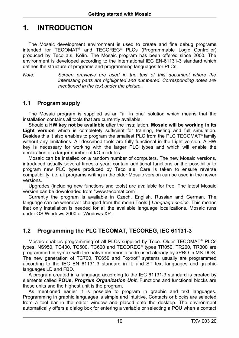
The Mosaic development environment is used to create and fine debug programs intended for TECOMAT® and TECOREG® PLCs (Programmable Logic Controller) produced by Teco a.s. Kolín. The Mosaic program has been offered since 2000. The environment is developed according to the international IEC EN-61131-3 standard which defines the structure of programs and programming languages for PLCs.
Note: Screen previews are used in the text of this document where the interesting parts are highlighted and numbered. Corresponding notes are mentioned in the text under the picture.
1.1 Program supply
The Mosaic program is supplied as an “all in one” solution which means that the installation contains all tools that are currently available.
Should a HW key not be available after the installation, Mosaic will be working in its Light version which is completely sufficient for training, testing and full simulation. Besides this it also enables to program the smallest PLC from the PLC TECOMAT® family without any limitations. All described tools are fully functional in the Light version. A HW key is necessary for working with the larger PLC types and which will enable the declaration of a larger number of I/O modules.
Mosaic can be installed on a random number of computers. The new Mosaic versions, introduced usually several times a year, contain additional functions or the possibility to program new PLC types produced by Teco a.s. Care is taken to ensure reverse compatibility, i.e. all programs writing in the older Mosaic version can be used in the newer versions.
Upgrades (including new functions and tools) are available for free. The latest Mosaic version can be downloaded from “www.tecomat.com”.
Currently the program is available in Czech, English, Russian and German. The language can be whenever changed from the menu Tools | Language choice. This means that only installation is needed for all the available language localizations. Mosaic runs under OS Windows 2000 or Windows XP.
1.2 Programming the PLC TECOMAT, TECOREG, IEC 61131-3
Mosaic enables programming of all PLCs supplied by Teco. Older TECOMAT® PLCs types: NS950, TC400, TC500, TC600 and TECOREG® types TR050, TR200, TR300 are programmed in syntax with the native mnemonic code used already by xPRO in MS-DOS. The new generation of TC700, TC650 and Foxtrot® systems usually are programmed according to the IEC EN 61131-3 standard in IL and ST text languages and graphic languages LD and FBD.
A program created in a language according to the IEC 61131-3 standard is created by elements called POUs, Program Organization Unit. Functions and functional blocks are these units and the highest unit is the program.
As mentioned earlier it is possible to program in graphic and text languages. Programming in graphic languages is simple and intuitive. Contacts or blocks are selected from a tool bar in the editor window and placed onto the desktop. The environment automatically offers a dialog box for entering a variable or selecting a POU when a contact
10 TXV 003 20
1. Úvod
of block is inserted. Variables and POUs can be in-advanced defined using an IEC manager or when used for the first time.
A similar automatization is offered in Mosaic and text languages. In the structured text language ST an IEC assistant can be used. The assistant offers to finish uncompleted construction, enables entering available variables, enables their defining, etc. Everything is accessible via hot-keys or via the right mouse click. When creating a program it is possible to combine parts of languages. However after choosing a certain language for a POU, this language cannot be changed. A following POU can have a different language. This enables to divide the program and e.g. create a part of the control logic in a LD language and a part with mathematical calculations and complicated expressions in a ST language.
The declaration part of the program is the same for all languages. All data types are supported which are defined in the above mentioned standard including data types for working with time, dates or strings. The declaration of own data types including structures and fields is supported as well as the declaration of all POU types.
The Mosaic environment has an integrated possibility to use block libraries and create own POU libraries.
11 TXV 003 20

Getting started with Mosaic
2. CREATING A NEW PROJECT
A project in MOSAIC is understood to be a program for one PLC including relevant files.Programs for control systems contain separate files. Some are created by the
programmer some automatically as a result of a special tool. Before beginning work in Mosaic we recommend to read the basic terminology stated in the manual: TXV 003 21 Programming TECOMAT® PLCs according to IEC 61 131.Basic terminology is:
• data types, • variables, • configurations, • sources and tasks, • POUs (functions, function blocks, programs),• programming languages (IL, ST, LD, FBD)
Each PLC project has to be part of a group of projects in the Mosaic environment. A group of projects contains at least one or more projects which are part of the entire control system network. PLC projects in a group may have communication links between each other and so create a common unit. Each project is created by a separate folder which contains all source and working files and information needed for programming a control system.
2.1 Running the Mosaic program
The initial dialog allows opening existing (already created) project groups. The existingproject groups are represented by files with extension “.mpr“(Mosaic Projects). For newproject group creation, press Cancel button and choose Project | New project group frommenu. Separate Mosaic windows will then appear.
After
12 TXV 003 20
2. Creating a new project
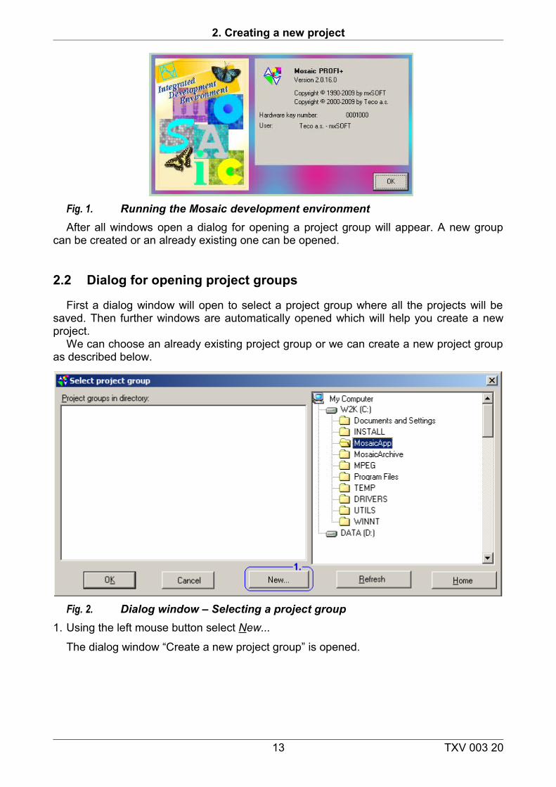
Fig. 1. Running the Mosaic development environmentAfter all windows open a dialog for opening a project group will appear. A new group
can be created or an already existing one can be opened.
2.2 Dialog for opening project groups
First a dialog window will open to select a project group where all the projects will be saved. Then further windows are automatically opened which will help you create a new project.
We can choose an already existing project group or we can create a new project group as described below.
Fig. 2. Dialog window – Selecting a project group1. Using the left mouse button select New...
The dialog window “Create a new project group” is opened.
13 TXV 003 20

Getting started with Mosaic
Fig. 1. Dialog window – Creating a project group1. enter the name of the new project group 2. press enter or click on OK.
We are then prompted to save and name the new project, i.e. the new PLC program. The dialog window “New project” is opened.
Fig. 2. Dialog window – New project1. enter the project’s new name or leave the default name PLC1 (to n).2. confirm clicking on “Open”.
The dialog window “Basic selection of control system” is opened. It will define the type of PLC from the Teco production on which the program will be running on. Older types (NS950, TC400, TC500, TC600), which do not support programming according to the IEC standard can be programmed by the original mnemonic code in MOSAIC.
14 TXV 003 20
2. Creating a new project
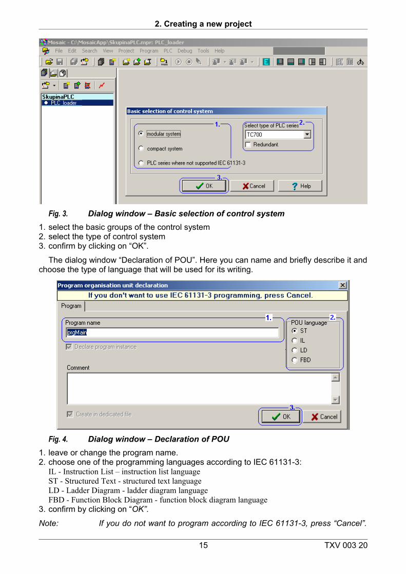
Fig. 3. Dialog window – Basic selection of control system1. select the basic groups of the control system2. select the type of control system3. confirm by clicking on “OK”.
The dialog window “Declaration of POU”. Here you can name and briefly describe it and choose the type of language that will be used for its writing.
Fig. 4. Dialog window – Declaration of POU1. leave or change the program name. 2. choose one of the programming languages according to IEC 61131-3: IL - Instruction List – instruction list language
ST - Structured Text - structured text languageLD - Ladder Diagram - ladder diagram languageFBD - Function Block Diagram - function block diagram language
3. confirm by clicking on “OK”.
Note: If you do not want to program according to IEC 61131-3, press “Cancel”.
15 TXV 003 20
Getting started with Mosaic
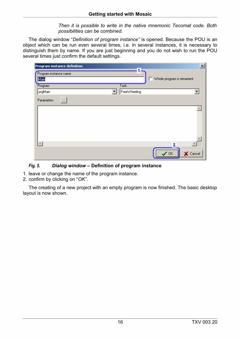
Then it is possible to write in the native mnemonic Tecomat code. Both possibilities can be combined.
The dialog window “Definition of program instance” is opened. Because the POU is an object which can be run even several times, i.e. in several instances, it is necessary to distinguish them by name. If you are just beginning and you do not wish to run the POU several times just confirm the default settings.
Fig. 5. Dialog window – Definition of program instance1. leave or change the name of the program instance. 2. confirm by clicking on “OK”.
The creating of a new project with an empty program is now finished. The basic desktop layout is now shown.
16 TXV 003 20
2. Creating a new project
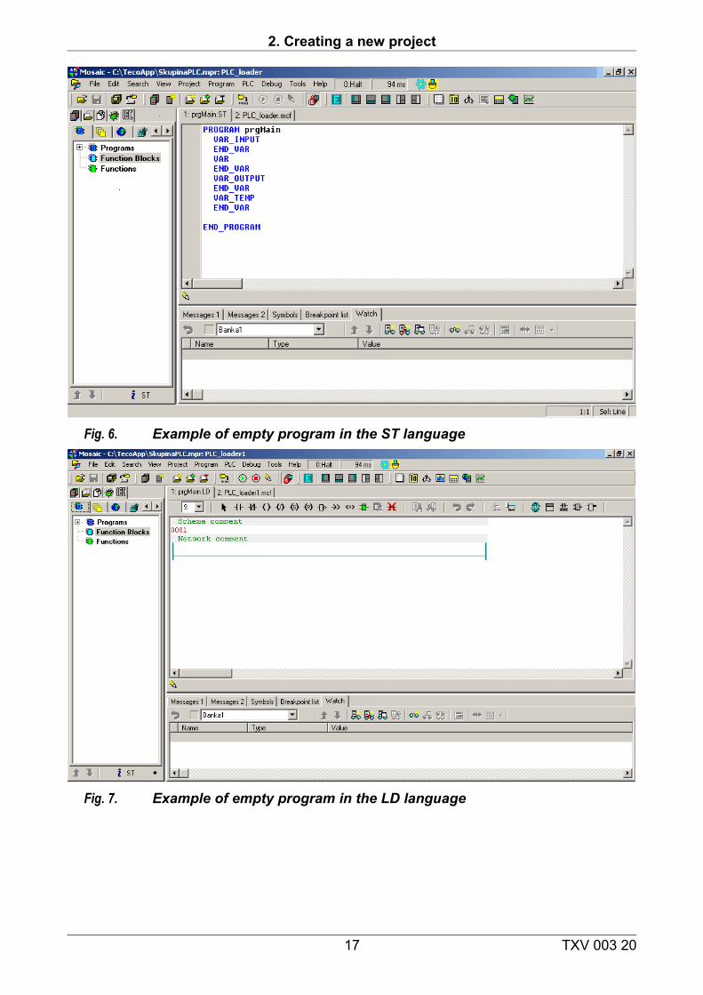
Fig. 6. Example of empty program in the ST language
Fig. 7. Example of empty program in the LD language
17 TXV 003 20
Getting started with Mosaic
3. BASIC DESCRIPTION OF THE MOSAIC ENVIRONMENT
3.1 Mosaic environment work panels
We will now describe the main window of the Mosaic programming language and its basic layout.
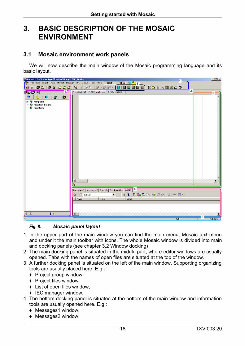
Fig. 8. Mosaic panel layout1. In the upper part of the main window you can find the main menu, Mosaic text menu
and under it the main toolbar with icons. The whole Mosaic window is divided into main and docking panels (see chapter 3.2 Window docking)
2. The main docking panel is situated in the middle part, where editor windows are usually opened. Tabs with the names of open files are situated at the top of the window.
3. A further docking panel is situated on the left of the main window. Supporting organizing tools are usually placed here. E.g.:♦ Project group window, ♦ Project files window, ♦ List of open files window,♦ IEC manager window.
4. The bottom docking panel is situated at the bottom of the main window and information tools are usually opened here. E.g.: ♦ Messages1 window,♦ Messages2 window,
18 TXV 003 20
3. Basic description of Mosaic environment
♦ Breakpoints list window♦ Data window.
5. The right docking panel is situated in the right part of the main window and is usually used to open preview tools for PLC memories and variables. E.g.: ♦ Accumulator window,♦ Memory 1 window,♦ Memory 2 window.
6. An information line is situated in the lowest line. Information texts are shown there and information from the active editor as number of line: column and editor working mode are shown on the right side.The size of the docking panels can be changed by dragging their frame and adjusting the size.
7. A group of control icons is situated in the main toolbar for easy changes in the desktop layout. Leaving the cursor above an icon will trigger a help bubble with the description of the icon.
3.2 Docking windows
Tool and editor windows can be situated into any panel by docking the window or they can be left in a floating window outside of the panel.
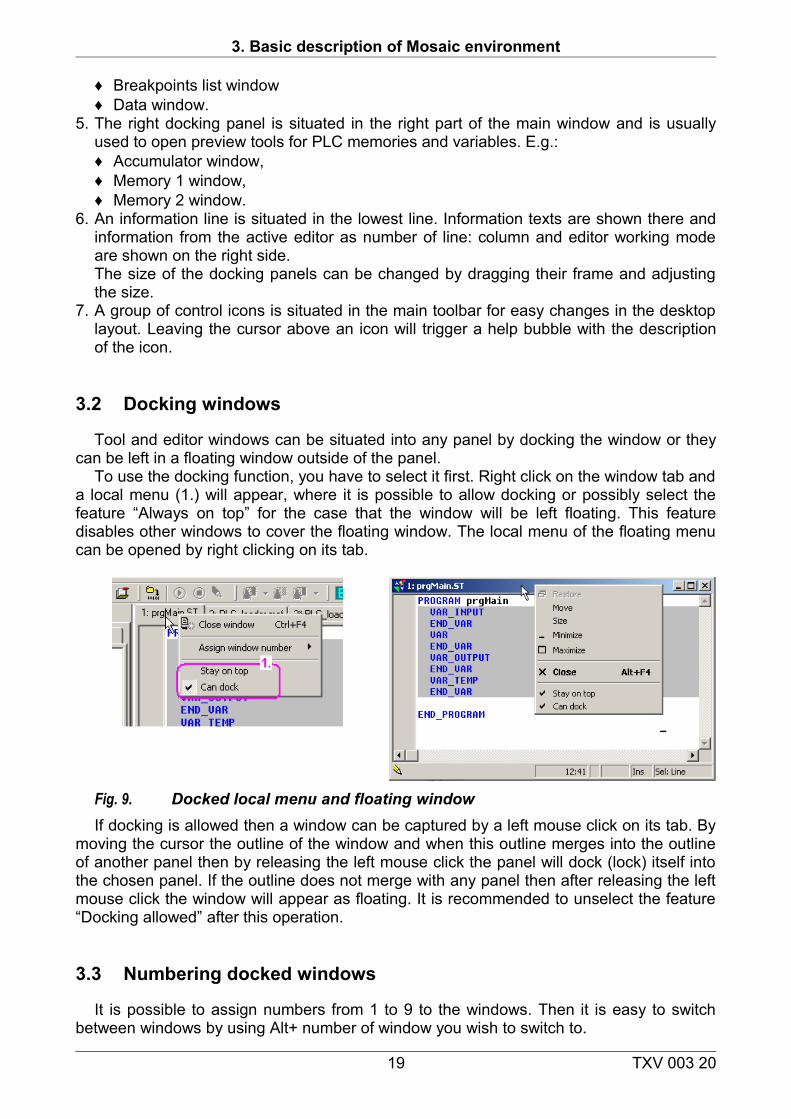
To use the docking function, you have to select it first. Right click on the window tab and a local menu (1.) will appear, where it is possible to allow docking or possibly select the feature “Always on top” for the case that the window will be left floating. This feature disables other windows to cover the floating window. The local menu of the floating menu can be opened by right clicking on its tab.
Fig. 9. Docked local menu and floating windowIf docking is allowed then a window can be captured by a left mouse click on its tab. By
moving the cursor the outline of the window and when this outline merges into the outline of another panel then by releasing the left mouse click the panel will dock (lock) itself into the chosen panel. If the outline does not merge with any panel then after releasing the left mouse click the window will appear as floating. It is recommended to unselect the feature “Docking allowed” after this operation.
3.3 Numbering docked windows
It is possible to assign numbers from 1 to 9 to the windows. Then it is easy to switch between windows by using Alt+ number of window you wish to switch to.
19 TXV 003 20
Getting started with Mosaic
3.4 Mosaic environment main menu
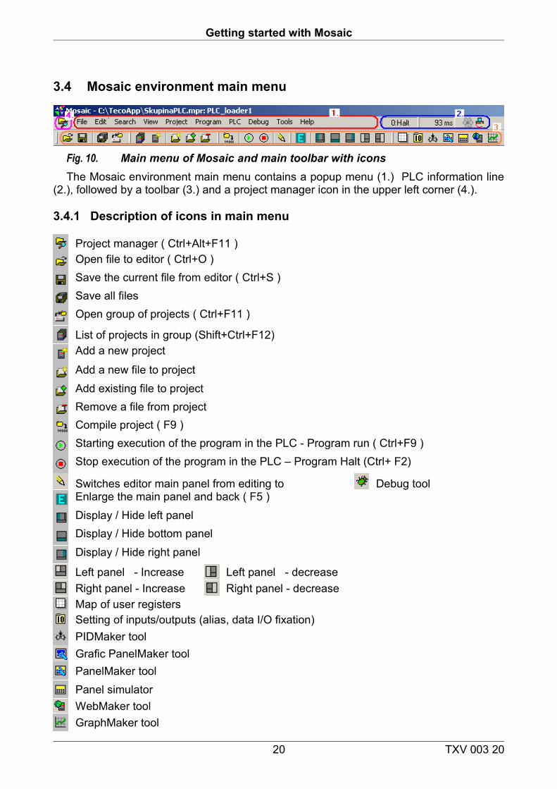
Fig. 10. Main menu of Mosaic and main toolbar with iconsThe Mosaic environment main menu contains a popup menu (1.) PLC information line
(2.), followed by a toolbar (3.) and a project manager icon in the upper left corner (4.).
3.4.1 Description of icons in main menu
Project manager ( Ctrl+Alt+F11 )Open file to editor ( Ctrl+O )Save the current file from editor ( Ctrl+S )Save all filesOpen group of projects ( Ctrl+F11 )
List of projects in group (Shift+Ctrl+F12)Add a new project
Add a new file to projectAdd existing file to projectRemove a file from projectCompile project ( F9 )Starting execution of the program in the PLC - Program run ( Ctrl+F9 )Stop execution of the program in the PLC – Program Halt (Ctrl+ F2)
Switches editor main panel from editing to Debug toolEnlarge the main panel and back ( F5 )Display / Hide left panelDisplay / Hide bottom panelDisplay / Hide right panel
Left panel - Increase Left panel - decreaseRight panel - Increase Right panel - decreaseMap of user registersSetting of inputs/outputs (alias, data I/O fixation)PIDMaker toolGrafic PanelMaker toolPanelMaker toolPanel simulatorWebMaker toolGraphMaker tool
20 TXV 003 20
3. Basic description of Mosaic environment
3.4.2 Information about PLC state in main menu toolbar
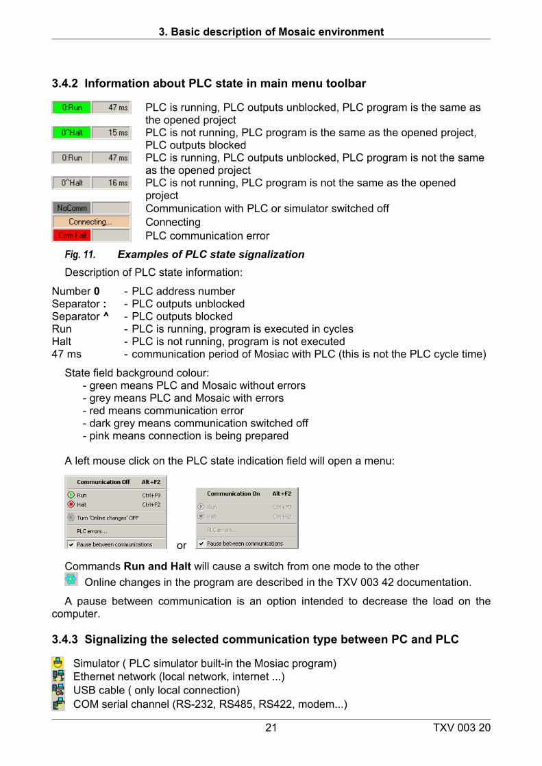
PLC is running, PLC outputs unblocked, PLC program is the same as the opened projectPLC is not running, PLC program is the same as the opened project, PLC outputs blockedPLC is running, PLC outputs unblocked, PLC program is not the same as the opened projectPLC is not running, PLC program is not the same as the opened projectCommunication with PLC or simulator switched off Connecting PLC communication error
Fig. 11. Examples of PLC state signalizationDescription of PLC state information:
Number 0 - PLC address numberSeparator : - PLC outputs unblockedSeparator ^ - PLC outputs blockedRun - PLC is running, program is executed in cyclesHalt - PLC is not running, program is not executed47 ms - communication period of Mosiac with PLC (this is not the PLC cycle time)
State field background colour:- green means PLC and Mosaic without errors - grey means PLC and Mosaic with errors- red means communication error- dark grey means communication switched off- pink means connection is being prepared
A left mouse click on the PLC state indication field will open a menu:
or
Commands Run and Halt will cause a switch from one mode to the otherOnline changes in the program are described in the TXV 003 42 documentation.
A pause between communication is an option intended to decrease the load on the computer.
3.4.3 Signalizing the selected communication type between PC and PLC
Simulator ( PLC simulator built-in the Mosiac program)Ethernet network (local network, internet ...)USB cable ( only local connection)COM serial channel (RS-232, RS485, RS422, modem...)
21 TXV 003 20
Getting started with Mosaic
4. OVERVIEW OF MOSAIC TOOLS
Tools for automatic code generating of parts of a programAll source codes of the user program may be created directly in a text form. For
minimizing mistakes and to make work easier the Mosaic development program is equipped with tools which make some tasks easier and automatically generate the final source text.
Some of these tools work in both directions, i.e. it is possible to program in the text form but also in with the graphic tools as necessary. The IEC manager enables this. Other tools work only one-way and generate an automatic source text. The resulting files are marked with the icon in the list of files for compilation and they cannot be edited in the text form and are read only types and are refreshed in accordance to tool settings.
Project manager (Ctrl-Alt-F11) is used for defining PLC types, their layout and settings of individual PLC modules. Further it is used for setting general functions of SW, communication drivers, interconnection between PLCs and also operator text panels which are included into this group of projects. It can be opened by clicking on the icon or from the menu Project and it is from default opened into a floating window in the upper part of the screen. It automatically generates parts of the program code with information about the system configuration saved in *.hwc, *.hwn, HWConfig.st and others.
Setting inputs/outputs (aliases, data and I/O fixation) The window displays input and output data and enables assigning names (aliases) to input and output signals, it also enables to fixate input and output values to random states during debugging. Further on it also displays the absolute input and output address after compilation. It enables assigning inputs and outputs a fixed absolute address. It can be opened by clicking on its icon and is by default opened in a floating window.
IEC manager is used for organizing and editing items in the user program in accordance with IEC 61 131-3. The IEC manager is opened automatically and is by default docked in the left panel. It is divided into several tabs:
POU - Program Organization Unit Types – variable types Global variables – globally available variables Configuration - organization of tasks and instances in program Libraries - overview of included libraries and their contents
Text editor of user programST text editor is used for the structured text language. The editor ensures the colour
highlighting according to language and tool syntax for editing. It is by default opened docked in the main panel for all *.st files.
IL text editor is used for the Instruction list language. The editor ensures the colour highlighting according to language syntax. It is by default opened docked in the main panel for all *.IL files.
Txt text editor is used for editing general text files without highlighting. It is by default opened docked in the main panel for all *.txt files.
Xpro text editor is used for the text language of the native mnemonic TECOMAT code. The editor ensures the colour highlighting according to language syntax. It is by
22 TXV 003 20
4. Overview of Mosaic tools
default opened docked in the main panel for all *.mos, *.mas, *.950, etc. files
Graphic editors for user programsEditor LD is used for the graphic ladder diagram with relay contacts. By default docked in
the main panel and with the suffix *.LD.Editor FBD is used for the graphic language of function blocks. By default docked in the
main panel and with the suffix *.FBD.Editor SFC (in preparation) used for creating transfer diagrams. By default docked in the
main panel and with the suffix *.SFC.Editor CFC (in preparation) used for drawing floating diagrams. By default docked in the
main panel and with the suffix *.CFC.IL - Instruction List – instruction list languageST - Structured Text - structured text languageLD - Ladder Diagram - ladder diagram languageFBD - Function Block Diagram - function block diagram language
Other tools for automatic generating of parts of codes of programs
PIDMaker is a visual attachment of the PID and PIDMA instruction of the PLC. It is used for easily implementing, debugging and correct regulation of algorithms. It can be opened by clicking on its icon and is by default docked into the left panel. Automatically generates parts of program codes with PID regulators (see TXV 003 26 documentation).
PanelMaker is used for defining the content text operator panels. It can be opened by clicking on its icon and is by default docked into the main panel. It automatically generates parts of program codes for working with HMI text panels. This function is only available if panel ID-xx is added to configuration in Project Manager | HW. Panel ID-xx can be connected to a communication channel in PLC network or added in HW configuration.
GraphicPanelMaker is used for defining the content graphic operator panels. It can be opened by clicking on its icon and is by default docked into the main panel. It automatically generates parts of program codes for working with HMI graphic panels. This function is only available if HMI graphic panel ID-xx is added to configuration in Project Manager | HW. Panel ID-xx can be added in HW configuration.
Tools for project management
Project groups shows all project group names in the current folder and names of the contained projects. It enables simple switching between projects. It is opened automatically and by default docked in the left panel.
Project files are used as an overview of project files that are included in the compilation and enable to change their order for the compilation. It is possible to manually shift the files but also add or delete the files in a project. Files are usually added into a project automatically by other tools like the IEC manager. It is opened automatically and by default docked in the left panel.
Opened files show a list of opened files and paths to their location and a list of floating windows are located in the bottom half. It is opened automatically and by default
23 TXV 003 20
Getting started with Mosaic
docked in the left panel.
Tools for debugging and simulations
POU Inspector is used for a basic view on the program when the PLC is in the RUN mode. It is really an editor window in a special mode. The source program is animated by the values of the current data so that the programmer can monitor the correctness of the written functions. It is opened directly in the active window instead of an editor.
WebMaker is used for creating XML pages for web servers in central units and basic modules which support such function. It can be used to show and set variables directly in MOSAIC. It can also be used as a simple visualization tool while debugging algorithms during simulations in MOSAIC. It is opened by clicking on its icon and by default it is docked in the main panel.
GraphMaker is used for the graphic display of up to 16 PLC variables in the form of a time graph. It has two modes:♦ as a memory oscilloscope ♦ as a logic and signal analyzer with a maximum resolution per one cycle run of the PLC program. It is opened by clicking on its icon and by default it is docked in the main panel (see document TXV 003 27).
Text panel simulator (HMI) is used for the testing of the program operators of the operator panel without HW attached. It is opened by clicking on its icon and by default it is opened in a floating window. It is recommended to set the window to “Always on top” by a right-click on the top bar of the window. It is possible to configure the tool by right-click in the window’s area.
Panel tool is used for semi-graphic displaying and setting program variables. It works as a simple visualization and is suitable for fine debugging algorithms in simulations. It can be opened from File/New/New panel. It is opened by default docked in the main panel on files with *.PAM suffixes. The tool can be found in the Mosaic environment due to compatibility issues with older systems. The above mentioned WebMaker is available for new applications offering graphics and higher comfort.
User register maps – shows the memory occupied with user %R user registers in the PLC and also enables checking for possible overlapping of definitions of variables. It is opened by clicking on its icon and by default it is opened in a floating window.
Messages 1 and Messages 2 window – shows messages from the compiler, search reports, tracing reports, etc. By left-clicking onto the displayed message you will be taken to the line regarding the message. The tool is opened by clicking on the its tab or in the menu “View | Other windows‘. By default it is docked in the bottom panel.
Symbols window - Displays symbolic names used in program after compilation. Left-click on item in the editor will send the cursor to the definition of the symbol. The tool is opened from the tab or menu “View | Symbols”. By default they are docked into the bottom panel.
List of breakpoints window - Displays a list of breakpoints inserted into the program by the user during debugging. Left-click on an item will display a dialog window for
24 TXV 003 20
4. Overview of Mosaic tools
setting up the conditions of the breakpoint. The tool is opened from the tab or menu “View | Breakpoint list”. By default they are docked into the bottom panel.
Data window - Displays data of user selected variables for monitoring their state and values during debugging. Double-click on a variable shows a dialog window with display conditions of the respective data item. Items can be grouped into more groups so called banks. The selection of items into banks is done via the local toolbar or by dragging and dropping from IEC manager tree. Order of items can be changed via arrows from the local toolbar. Tools are opened by clicking onto their tab or via menu “View|Data”. By default the window is opened docked into the bottom panel.
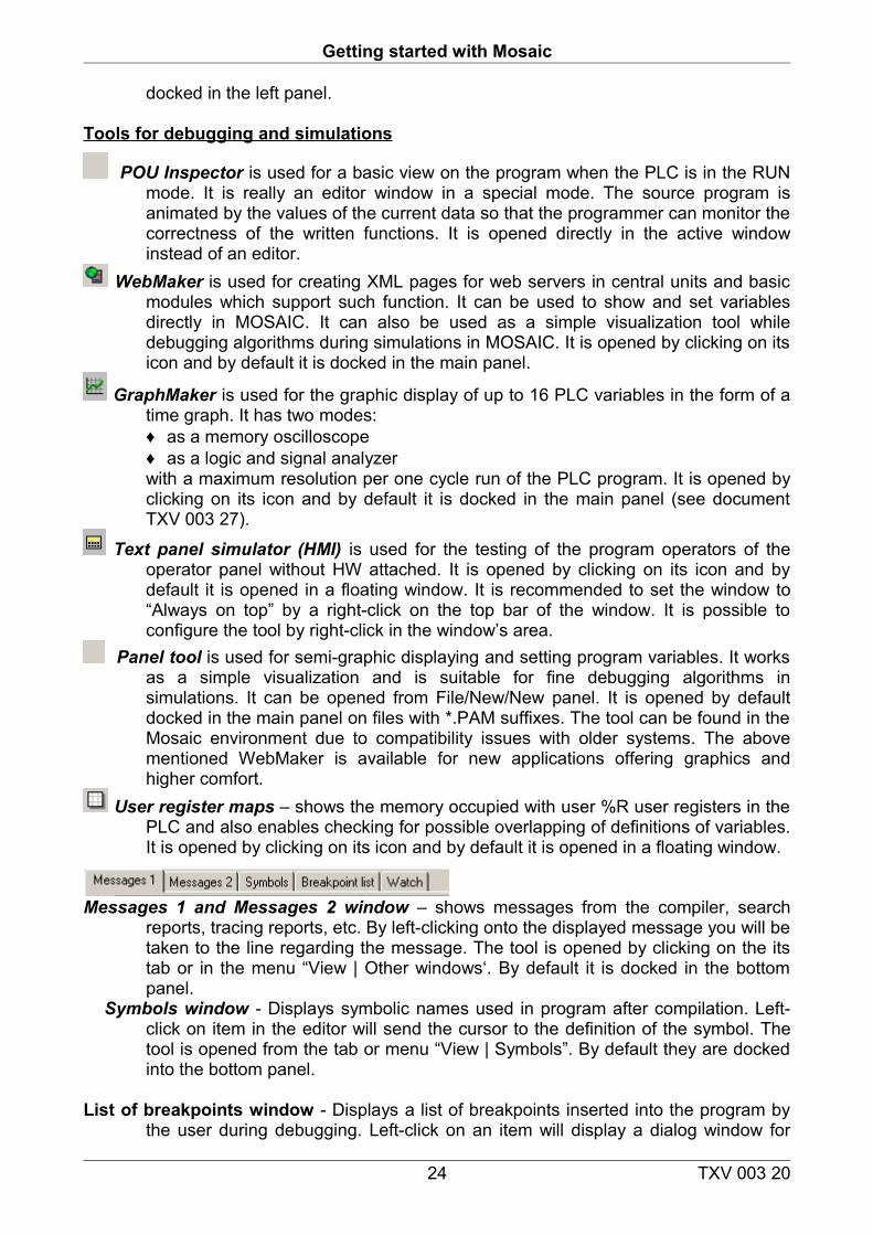
Accumulator window - Displays accumulator data in a PLC for monitoring during debugging in mnemonic code (*.mos). Accumulators are memory locations above which instruction are executed. Right-click displays a dialog window for setting the format of the respective item. The tool is opened via tab or menu “View | Accumulators”. By default the window is docked into the right panel.
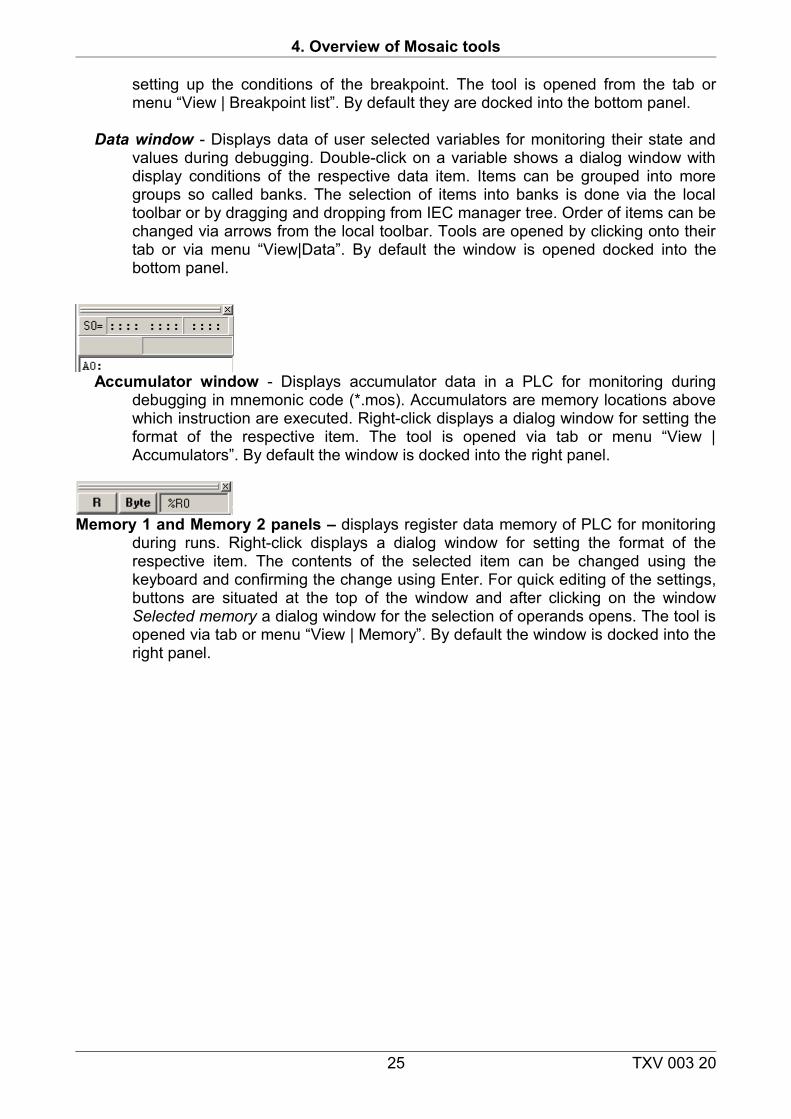
Memory 1 and Memory 2 panels – displays register data memory of PLC for monitoring during runs. Right-click displays a dialog window for setting the format of the respective item. The contents of the selected item can be changed using the keyboard and confirming the change using Enter. For quick editing of the settings, buttons are situated at the top of the window and after clicking on the window Selected memory a dialog window for the selection of operands opens. The tool is opened via tab or menu “View | Memory”. By default the window is docked into the right panel.
25 TXV 003 20
Getting started with Mosaic
5. PROJECT MANAGER
Used to define PLC type, to set it up and adjust individual functions of the PLC module. Used for setting general SW driver functions for communication, interconnected data transfers between PLC projects and also operator text panels which included into such project group. It automatically generates parts of program codes regarding system configuration which are saved in files with the suffixes: *.hwc, *.hwn, HWConfig.st and other.
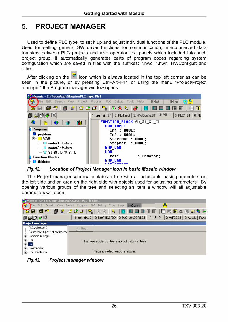
After clicking on the icon which is always located in the top left corner as can be seen in the picture, or by pressing Ctrl+Alt+F11 or using the menu “Project/Project manager” the Program manager window opens.
Fig. 12. Location of Project Manager icon in basic Mosaic windowThe Project manager window contains a tree with all adjustable basic parameters on
the left side and an area on the right side with objects used for adjusting parameters. By opening various groups of the tree and selecting an item a window will all adjustable parameters will open.
Fig. 13. Project manager window
26 TXV 003 20
5. Project Manager
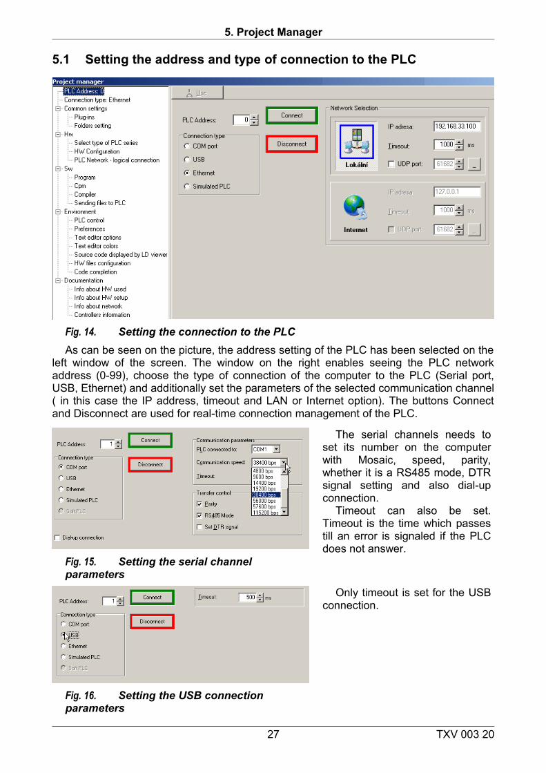
5.1 Setting the address and type of connection to the PLC
Fig. 14. Setting the connection to the PLCAs can be seen on the picture, the address setting of the PLC has been selected on the
left window of the screen. The window on the right enables seeing the PLC network address (0-99), choose the type of connection of the computer to the PLC (Serial port, USB, Ethernet) and additionally set the parameters of the selected communication channel ( in this case the IP address, timeout and LAN or Internet option). The buttons Connect and Disconnect are used for real-time connection management of the PLC.
Fig. 15. Setting the serial channel parameters
The serial channels needs to set its number on the computer with Mosaic, speed, parity, whether it is a RS485 mode, DTR signal setting and also dial-up connection.
Timeout can also be set. Timeout is the time which passes till an error is signaled if the PLC does not answer.
Fig. 16. Setting the USB connection parameters
Only timeout is set for the USB connection.
27 TXV 003 20
Getting started with Mosaic
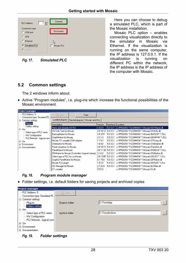
Fig. 17. Simulated PLC
Here you can choose to debug a simulated PLC, which is part of the Mosaic installation.
Mosaic PLC option – enables connecting visualization directly to the simulator in Mosaic via Ethernet. If the visualization is running on the same computer, the IP address is 127.0.0.1. If the visualization is running on different PC within the network, the IP address is the IP address of the computer with Mosaic.
5.2 Common settings
The 2 windows inform about:
♦ Active “Program modules”, i.e. plug-ins which increase the functional possibilities of the Mosaic environment.
Fig. 18. Program module manager♦ Folder settings, i.e. default folders for saving projects and archived copies
Fig. 19. Folder settings
28 TXV 003 20
5. Project Manager
5.3 HW configurator
5.3.1 PLC series selecting
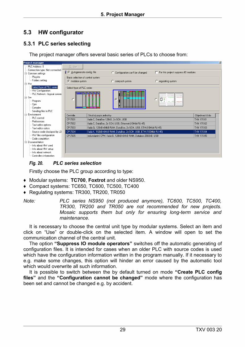
The project manager offers several basic series of PLCs to choose from:
Fig. 20. PLC series selectionFirstly choose the PLC group according to type:
♦ Modular systems: TC700, Foxtrot and older NS950. ♦ Compact systems: TC650, TC600, TC500, TC400♦ Regulating systems: TR300, TR200, TR050
Note: PLC series NS950 (not produced anymore), TC600, TC500, TC400, TR300, TR200 and TR050 are not recommended for new projects. Mosaic supports them but only for ensuring long-term service and maintenance.
It is necessary to choose the central unit type by modular systems. Select an item and click on “Use” or double-click on the selected item. A window will open to set the communication channel of the central unit.
The option “Suppress IO module operators” switches off the automatic generating of configuration files. It is intended for cases when an older PLC with source codes is used which have the configuration information written in the program manually. If it necessary to e.g. make some changes, this option will hinder an error caused by the automatic tool which would overwrite all such information.
It is possible to switch between the by default turned on mode “Create PLC config files” and the “Configuration cannot be changed” mode where the configuration has been set and cannot be changed e.g. by accident.
29 TXV 003 20
Getting started with Mosaic
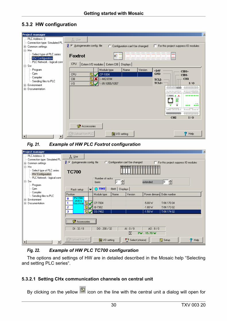
5.3.2 HW configuration
Fig. 21. Example of HW PLC Foxtrot configuration
Fig. 22. Example of HW PLC TC700 configurationThe options and settings of HW are in detailed described in the Mosaic help “Selecting
and setting PLC series“.
5.3.2.1 Setting CHx communication channels on central unit
By clicking on the yellow icon on the line with the central unit a dialog will open for
30 TXV 003 20
5. Project Manager
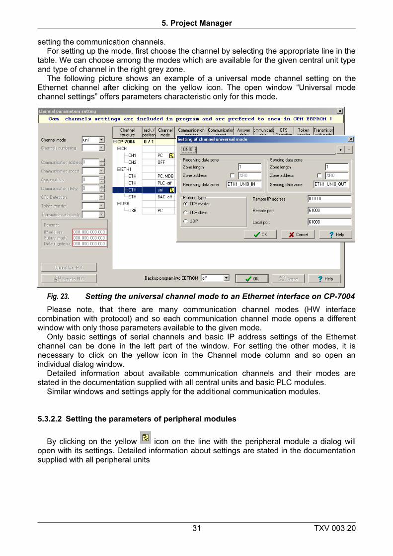
setting the communication channels.For setting up the mode, first choose the channel by selecting the appropriate line in the
table. We can choose among the modes which are available for the given central unit type and type of channel in the right grey zone.
The following picture shows an example of a universal mode channel setting on the Ethernet channel after clicking on the yellow icon. The open window “Universal mode channel settings” offers parameters characteristic only for this mode.
Fig. 23. Setting the universal channel mode to an Ethernet interface on CP-7004Please note, that there are many communication channel modes (HW interface
combination with protocol) and so each communication channel mode opens a different window with only those parameters available to the given mode.
Only basic settings of serial channels and basic IP address settings of the Ethernet channel can be done in the left part of the window. For setting the other modes, it is necessary to click on the yellow icon in the Channel mode column and so open an individual dialog window.
Detailed information about available communication channels and their modes are stated in the documentation supplied with all central units and basic PLC modules.
Similar windows and settings apply for the additional communication modules.
5.3.2.2 Setting the parameters of peripheral modules
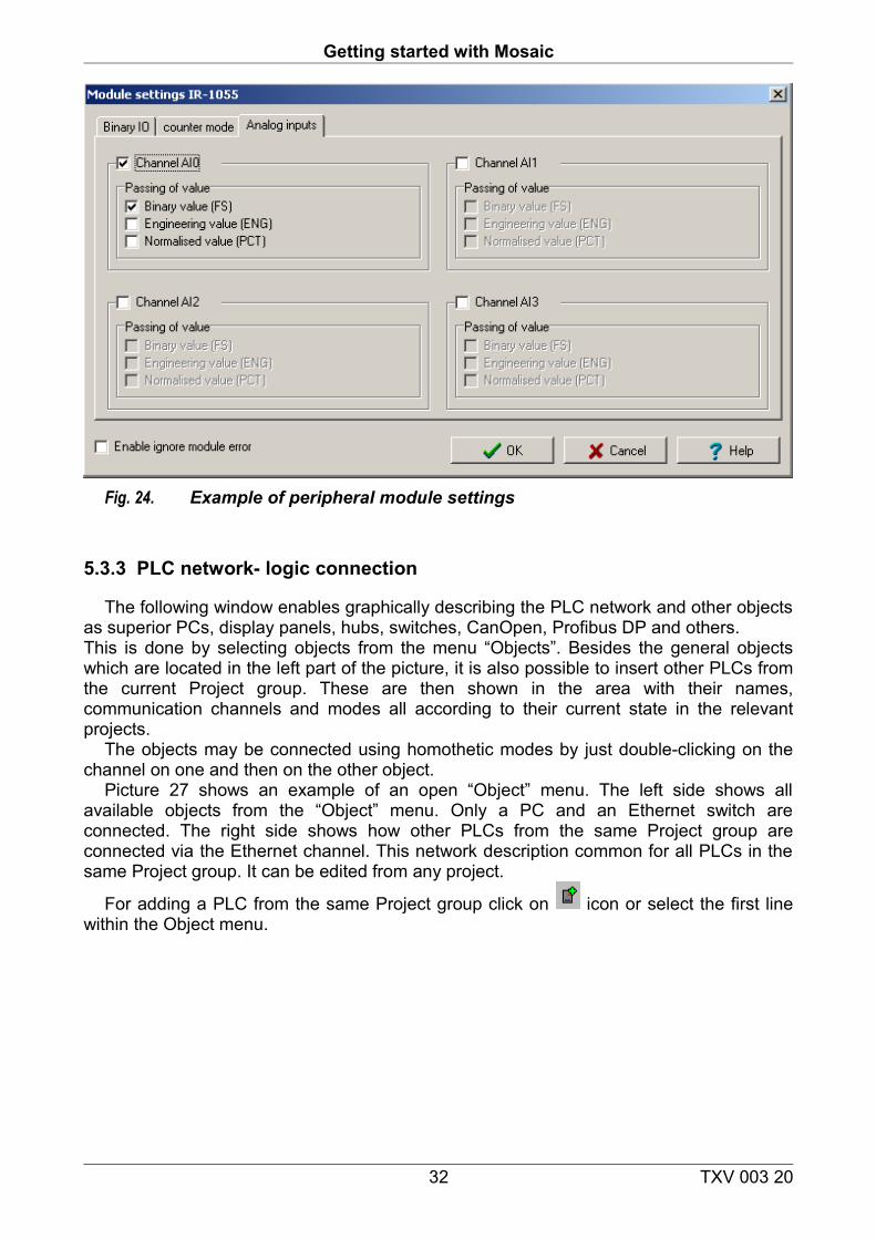
By clicking on the yellow icon on the line with the peripheral module a dialog will open with its settings. Detailed information about settings are stated in the documentation supplied with all peripheral units
31 TXV 003 20
Getting started with Mosaic
Fig. 24. Example of peripheral module settings
5.3.3 PLC network- logic connection
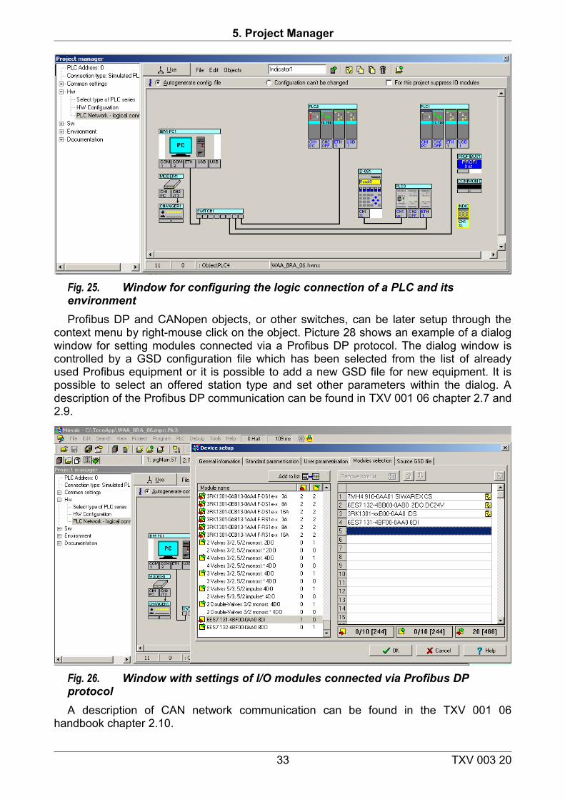
The following window enables graphically describing the PLC network and other objects as superior PCs, display panels, hubs, switches, CanOpen, Profibus DP and others.This is done by selecting objects from the menu “Objects”. Besides the general objects which are located in the left part of the picture, it is also possible to insert other PLCs from the current Project group. These are then shown in the area with their names, communication channels and modes all according to their current state in the relevant projects.
The objects may be connected using homothetic modes by just double-clicking on the channel on one and then on the other object.
Picture 27 shows an example of an open “Object” menu. The left side shows all available objects from the “Object” menu. Only a PC and an Ethernet switch are connected. The right side shows how other PLCs from the same Project group are connected via the Ethernet channel. This network description common for all PLCs in the same Project group. It can be edited from any project.
For adding a PLC from the same Project group click on icon or select the first line within the Object menu.
32 TXV 003 20
5. Project Manager
Fig. 25. Window for configuring the logic connection of a PLC and its environmentProfibus DP and CANopen objects, or other switches, can be later setup through the
context menu by right-mouse click on the object. Picture 28 shows an example of a dialog window for setting modules connected via a Profibus DP protocol. The dialog window is controlled by a GSD configuration file which has been selected from the list of already used Profibus equipment or it is possible to add a new GSD file for new equipment. It is possible to select an offered station type and set other parameters within the dialog. A description of the Profibus DP communication can be found in TXV 001 06 chapter 2.7 and 2.9.
Fig. 26. Window with settings of I/O modules connected via Profibus DP protocolA description of CAN network communication can be found in the TXV 001 06
handbook chapter 2.10.
33 TXV 003 20
Getting started with Mosaic
Fig. 27. Window with settings of I/O modules connected via CAN protocol
5.4 SW configurator
5.4.1 Application program and library information window
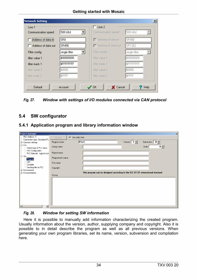
Fig. 28. Window for setting SW informationHere it is possible to manually add information characterizing the created program.
Usually information about the version, author, supplying company and copyright. Also it is possible to in detail describe the program as well as all previous versions. When generating your own program libraries, set its name, version, subversion and compilation here.
34 TXV 003 20
5. Project Manager
5.4.2 Window for setting PLC central units
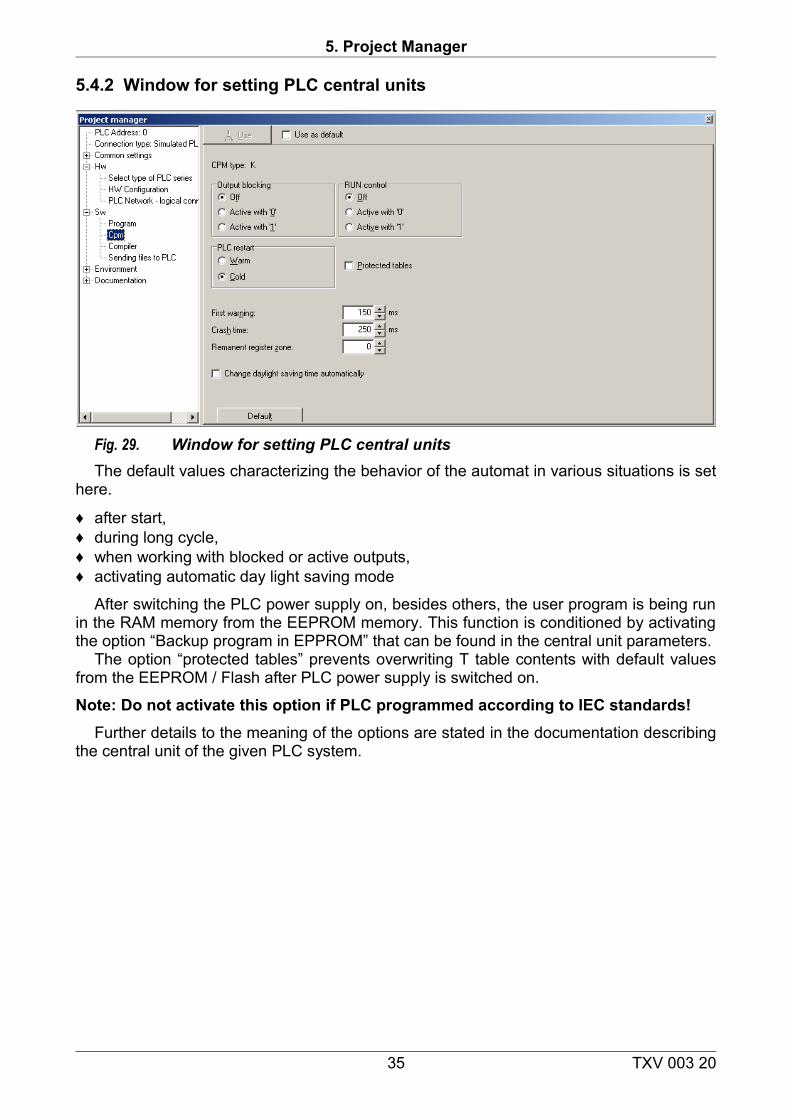
Fig. 29. Window for setting PLC central unitsThe default values characterizing the behavior of the automat in various situations is set
here.
♦ after start, ♦ during long cycle,♦ when working with blocked or active outputs,♦ activating automatic day light saving mode
After switching the PLC power supply on, besides others, the user program is being run in the RAM memory from the EEPROM memory. This function is conditioned by activating the option “Backup program in EPPROM” that can be found in the central unit parameters.
The option “protected tables” prevents overwriting T table contents with default values from the EEPROM / Flash after PLC power supply is switched on.
Note: Do not activate this option if PLC programmed according to IEC standards!Further details to the meaning of the options are stated in the documentation describing
the central unit of the given PLC system.
35 TXV 003 20
Getting started with Mosaic
5.4.3 Compiler settings window
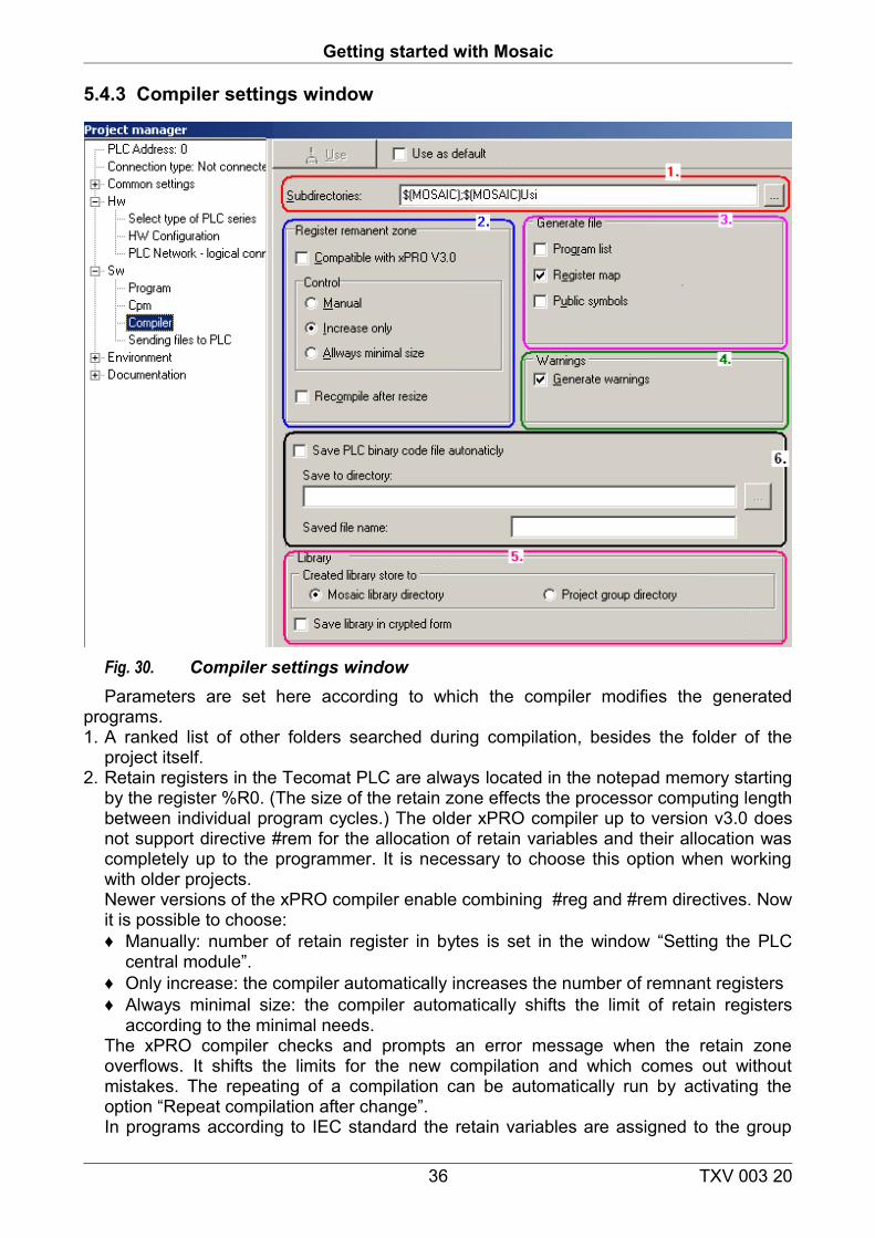
Fig. 30. Compiler settings windowParameters are set here according to which the compiler modifies the generated
programs.1. A ranked list of other folders searched during compilation, besides the folder of the
project itself.2. Retain registers in the Tecomat PLC are always located in the notepad memory starting
by the register %R0. (The size of the retain zone effects the processor computing length between individual program cycles.) The older xPRO compiler up to version v3.0 does not support directive #rem for the allocation of retain variables and their allocation was completely up to the programmer. It is necessary to choose this option when working with older projects.Newer versions of the xPRO compiler enable combining #reg and #rem directives. Now it is possible to choose:♦ Manually: number of retain register in bytes is set in the window “Setting the PLC
central module”.♦ Only increase: the compiler automatically increases the number of remnant registers♦ Always minimal size: the compiler automatically shifts the limit of retain registers
according to the minimal needs.The xPRO compiler checks and prompts an error message when the retain zone overflows. It shifts the limits for the new compilation and which comes out without mistakes. The repeating of a compilation can be automatically run by activating the option “Repeat compilation after change”. In programs according to IEC standard the retain variables are assigned to the group
36 TXV 003 20
5. Project Manager
VAR_GLOBAL RETAIN and the assignment of necessary registers is done automatically during compilation.
3. Before the compilation it is possible to activate the option for generating information into: ♦ detailed program report (*.lst), ♦ register allocation map (*.map) ♦ file with public name - public (*.pub)
4. It is possible to suppress generating of alert messages into the window “Messages”. It is not recommended to do so. The compiler alerts are useful because they may signalize mistakes made by the programmer!
5. From generating your own library from your project, a target can be set, i.e. one from two folders for its saving.
5.5 Environment configurator
5.5.1 PLC control window
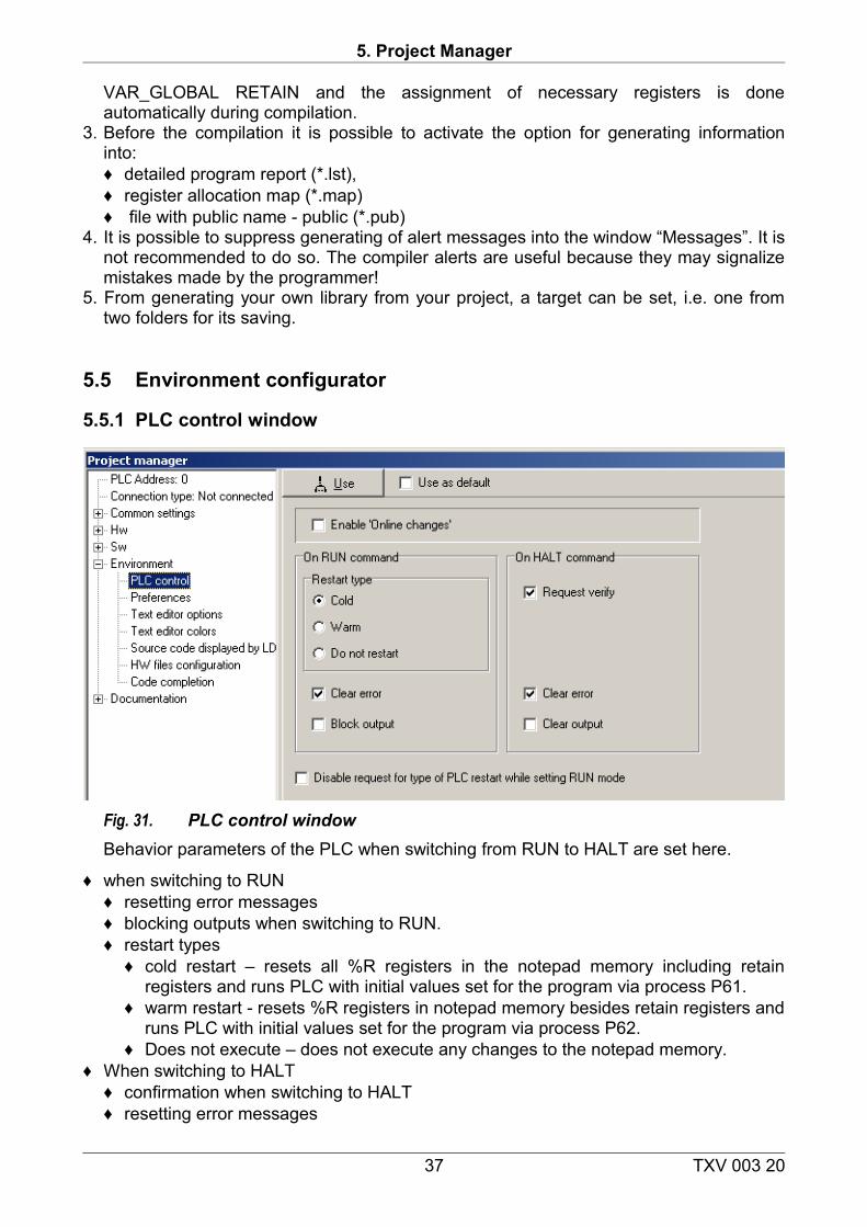
Fig. 31. PLC control windowBehavior parameters of the PLC when switching from RUN to HALT are set here.
♦ when switching to RUN ♦ resetting error messages♦ blocking outputs when switching to RUN. ♦ restart types
♦ cold restart – resets all %R registers in the notepad memory including retain registers and runs PLC with initial values set for the program via process P61.
♦ warm restart - resets %R registers in notepad memory besides retain registers and runs PLC with initial values set for the program via process P62.
♦ Does not execute – does not execute any changes to the notepad memory.♦ When switching to HALT
♦ confirmation when switching to HALT♦ resetting error messages
37 TXV 003 20
Getting started with Mosaic
♦ resetting output module states (blocking outputs when switching to HALT is always done).
♦ OnLine program changes option (description of OnLine programming can be found the document TXV 033 42).
5.5.2 Other environment configuration windows
Here the environment behavior parameters are set, which are easily understood thanks to their names. It is good to mention the note regarding the HW file configuration parameter:
During project compilation, the order of compilation is managed by the list (see tool “Project group”) and automatic tools insert their products automatically forward. When creating some libraries, it is necessary to shift completely forward some definition parts of the source code. For this case, it is possible to use the option switch off automatic file order change.
5.6 Documentation windows
Information in text form is shown here regarding the settings of PLC HW and SW.
38 TXV 003 20
6. Setting inputs and outputs
6. SETTING INPUTS AND OUTPUTS
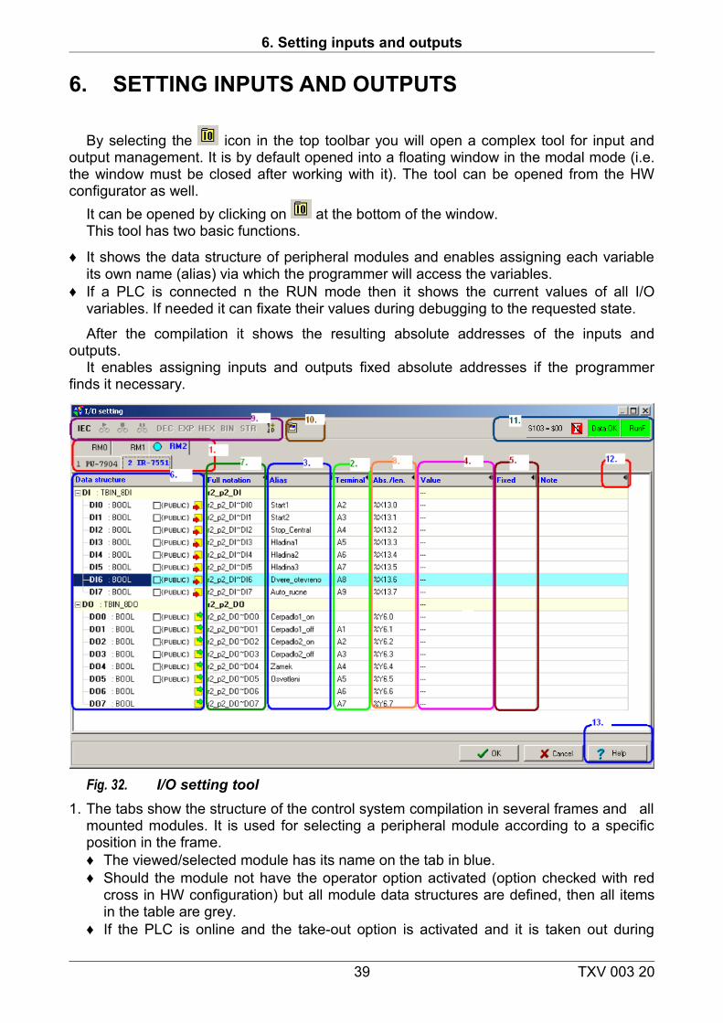
By selecting the icon in the top toolbar you will open a complex tool for input and output management. It is by default opened into a floating window in the modal mode (i.e. the window must be closed after working with it). The tool can be opened from the HW configurator as well.
It can be opened by clicking on at the bottom of the window.This tool has two basic functions.
♦ It shows the data structure of peripheral modules and enables assigning each variable its own name (alias) via which the programmer will access the variables.
♦ If a PLC is connected n the RUN mode then it shows the current values of all I/O variables. If needed it can fixate their values during debugging to the requested state.
After the compilation it shows the resulting absolute addresses of the inputs and outputs.
It enables assigning inputs and outputs fixed absolute addresses if the programmer finds it necessary.
Fig. 32. I/O setting tool1. The tabs show the structure of the control system compilation in several frames and all
mounted modules. It is used for selecting a peripheral module according to a specific position in the frame.♦ The viewed/selected module has its name on the tab in blue.♦ Should the module not have the operator option activated (option checked with red
cross in HW configuration) but all module data structures are defined, then all items in the table are grey.
♦ If the PLC is online and the take-out option is activated and it is taken out during
39 TXV 003 20
Getting started with Mosaic
running, then the name is struck through.♦ If the name is red, then the module has some fixed signals.
2. Terminal Label of terminal on module connector.
3. Alias A variable assigned to a specific input/output is randomly named. Changes made to the names are only accepted after the program is compiled and written into the PLC.
4. Value shows the current value of the inputs/outputs of the connected or simulated PLC
5. Fixation Fixation of a variable value during debugging an algorithm. This function can be useful when starting new controlled technologies. ♦ Inputs here they can be set to a value which is not affected by the actual current
state of the module input. ♦ Outputs here they can be set to a value which is not affected by the program.
6. Data structure the tree structure of the data available to a selected module. This regards not only direct inputs and outputs but also information about state, keywords, ranges, etc.♦ The icon in the right part of the column shows whether the item is a input or output♦ The PUBLIC option enables exporting the Alias by chosen inputs and outputs into
files which are used for importing names for visualization tools (SCADA systems)
7. Complete record Automatic/by default assigned system name of variable to structure: frame_position_input/output_
8. Abs/length absolute address of variable or length of variable in bytes.
9. Toolbar with buttons for selecting manner of view -♦ IEC switches the recording format of absolute names according to the IEC
standard (%I %Q) or according to the Tecomat syntax %X %Y ♦ Start, ♦ Stop, ♦ Freeze
sets the behavior of the view manner in the column Value♦ DEC, EXP, HEX, BIN, STR – options for the view manner in the column Value♦ Signum – shows data with or without sign
10. „Map of inputs’ and outputs’ occupation” see description of tool below
11. State information – set of information which shows: ♦ signal of switched on fixation mode,♦ signal of validity of displayed data,♦ working mode of connected PLC (RUN/HALT) and communication state.
12. Buttons for suppressing display of table columns and vice versa .
13. Help opens help for variables in the data structure of the selected I/O module.
6.1 Alias – naming input and output signals
Every peripheral PLC module has, according to its type, its input and output data
40 TXV 003 20
6. Setting inputs and outputs
organized into data structures. When configuring a PLC, symbolic names (3.) are assigned to each input and output of every module in the set according to the methodology described in the following examples. Symbolic names eliminate the worries of the programmers regarding the assignment of absolute addresses into notepad memories for each input or output and enable easier program portability.
To make the record well-arranged for the programmer, he can assign is own symbolic name to the inputs and outputs. Usually he will use the name of the connected sensor, device or measured value. This next user symbolic name is called an Alias and is assigned in the Alias column. The system checks the requested uniqueness of these names within the frame of the whole project.
Example 1:The binary input module IB-7302 contains input signals organized into 32 BOOL type
variables. Its name is r0_p3_DI, where:
♦ r0 means the frame with the address 0, ♦ p3 means position 3 within the frame and ♦ DI means binary inputs.
The fourth bit has the system name r0_p3_DI.DI3. The programmer can assign each signal a proper noun, a so called “alias” which
describes the function of the signal. E.g. „myName13“. Later on he can use this proper noun (8.) instead of more complicated system names of this signal.
Example 2:The analog input module IT-7604 contains 8 analog channels with the system names
r0_p9_AI0 to r0_p9_AI7. Their data structure contains their own measured values and bit flags. E.g. overflow underflow of range etc. Each channel can be assigned an alias as a whole, e.g. “TEMPERATURE1” then the own measuring would be “TEMPERATURE1.ENG”. Or we can just name the measured value e.g. “TEMPERATURE”. Later on in the program, we can use this name instead of more complicated system names of this signal.
The names of I/O signals should be assigned before writing the program.
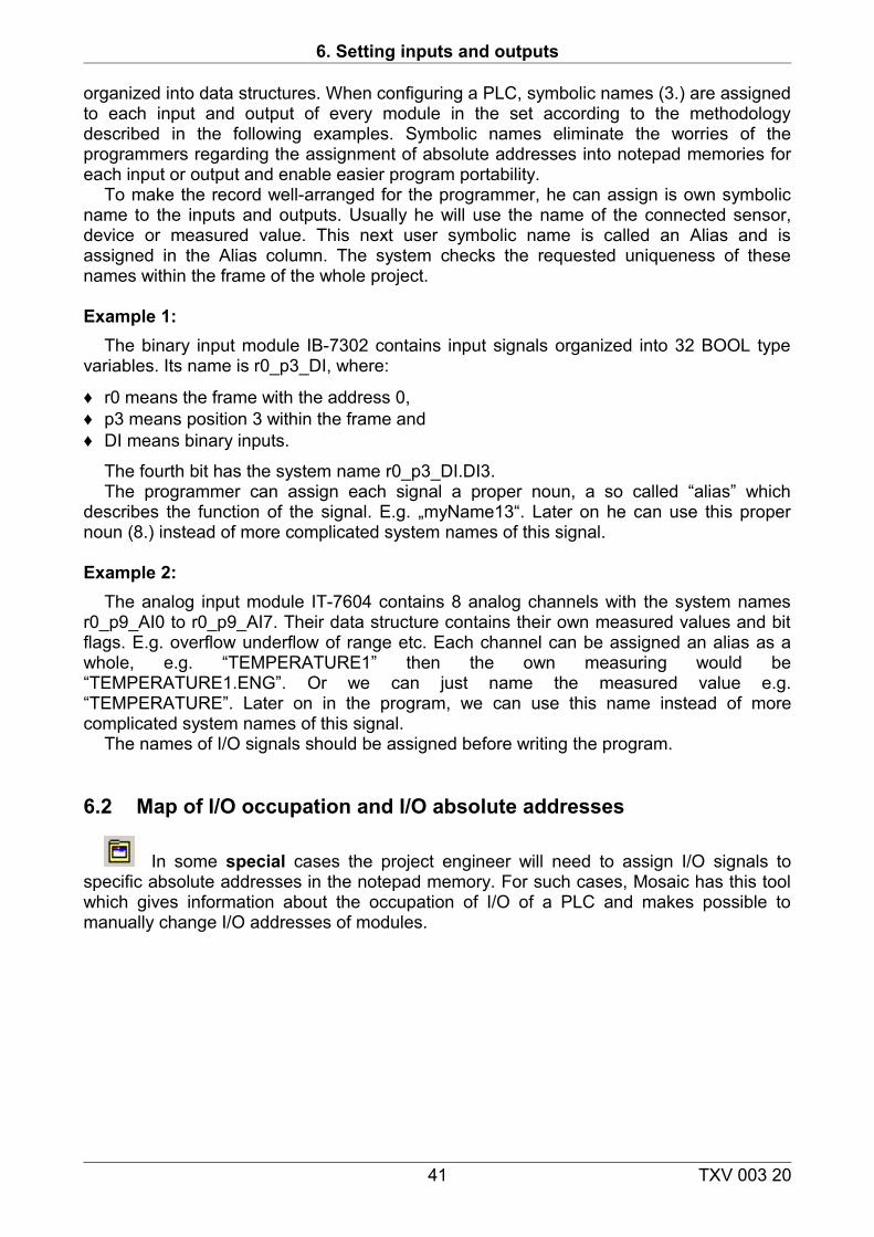
6.2 Map of I/O occupation and I/O absolute addresses
In some special cases the project engineer will need to assign I/O signals to specific absolute addresses in the notepad memory. For such cases, Mosaic has this tool which gives information about the occupation of I/O of a PLC and makes possible to manually change I/O addresses of modules.
41 TXV 003 20
Getting started with Mosaic
Fig. 33. I/O occupation map - inputs1. Selection of zone of inputs or outputs2. Field for assigning absolute position of peripheral module3. Optimalization button, i.e. shift of all free modules to a lowest possible address.4. Map of addresses with coloured occupied addresses5. Selected module – Moving cursor above coloured part displays the specific module
and its data.6. Button for stepping: per individual module
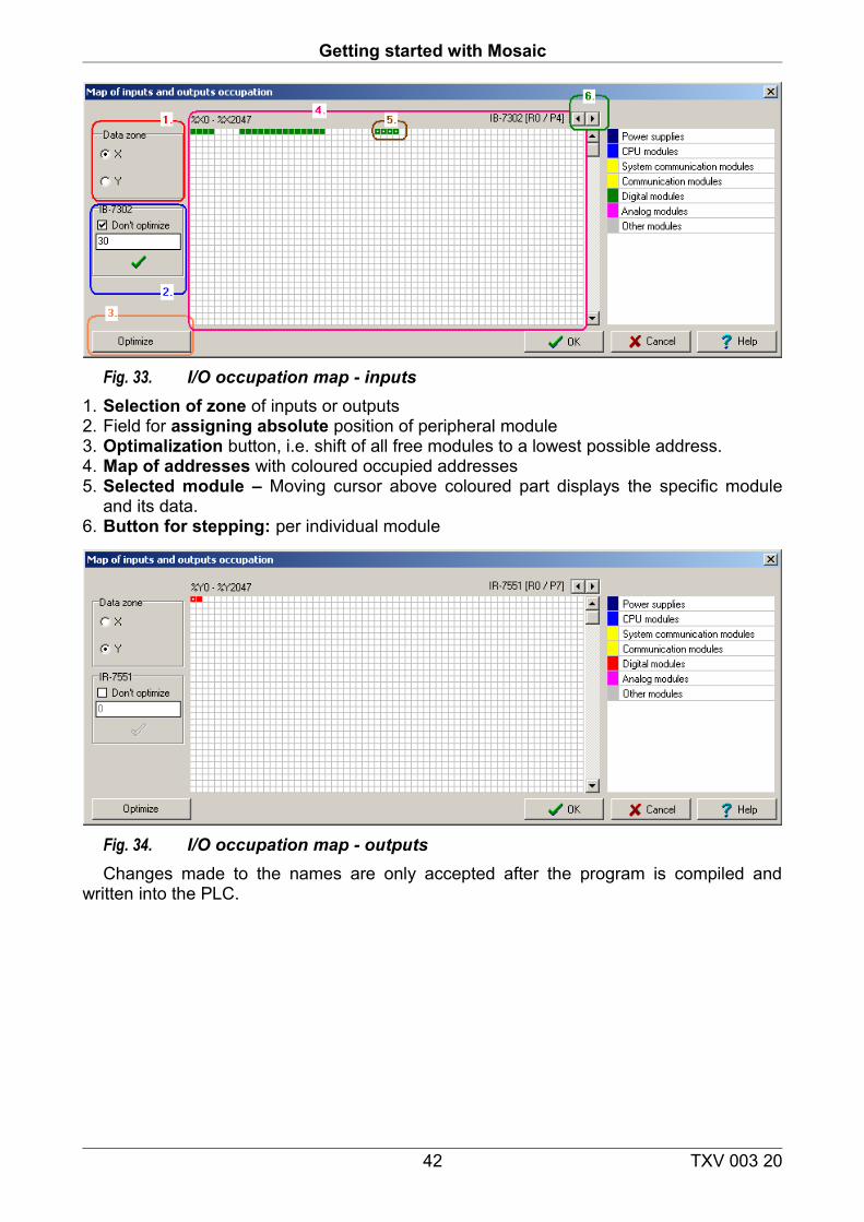
Fig. 34. I/O occupation map - outputsChanges made to the names are only accepted after the program is compiled and
written into the PLC.
42 TXV 003 20
7. IEC manager
7. IEC MANAGER
IEC manager. Is used for organizing and editing items in the user program according to IEC 61 131-3. The IEC manager is opened automatically and is by default docked in the left panel. It is divided into several tabs which can be described as follows:
♦ POU – programmable organizational units ♦ Types – variable types♦ Global variables – globally available variables ♦ Configuration - organization of tasks and program items ♦ Libraries - overview of included libraries and their content
7.1 Local menu in IEC manager window
The IEC manager helps generate
♦ POUs, ♦ data types, ♦ variables, ♦ configurator program tasks ♦ Adding or removing libraries.
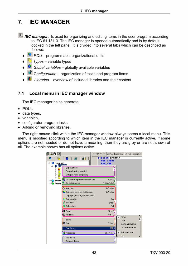
The right-mouse click within the IEC manager window always opens a local menu. This menu is modified according to which item in the IEC manager is currently active. If some options are not needed or do not have a meaning, then they are grey or are not shown at all. The example shown has all options active.
43 TXV 003 20
Getting started with Mosaic
Fig. 35. Example of local menu in the IEC manager1. Controlling groups in a tree of IEC manager items. Opening and closing of tree groups
can be done by left-mouse click on the group sign + /-.2 Context transfer to a text source of item.3. Adding and editing of tree items.4. Searching in tree items.5. Select – selection of entire item in text format.
Copy – complete item name into clipboard.6. Item order in tree according to criteria.7. Features of selected item. 8. Adding and removing libraries. System libraries cannot be removed.
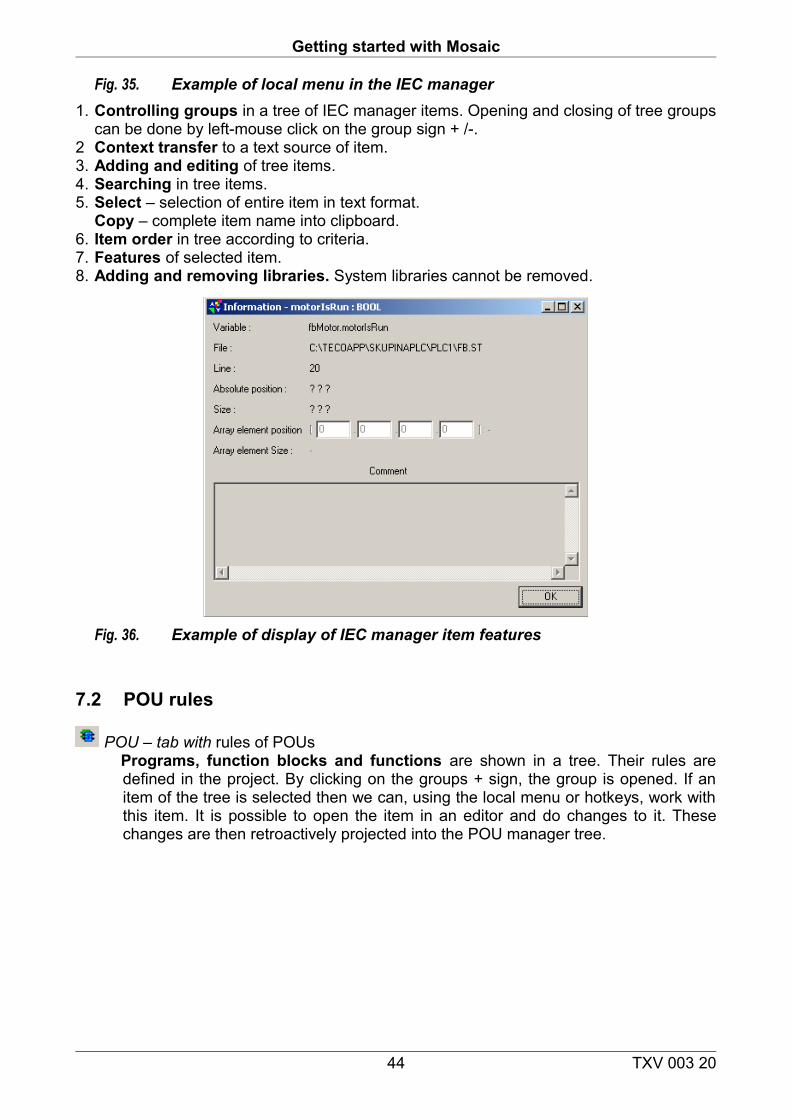
Fig. 36. Example of display of IEC manager item features
7.2 POU rules
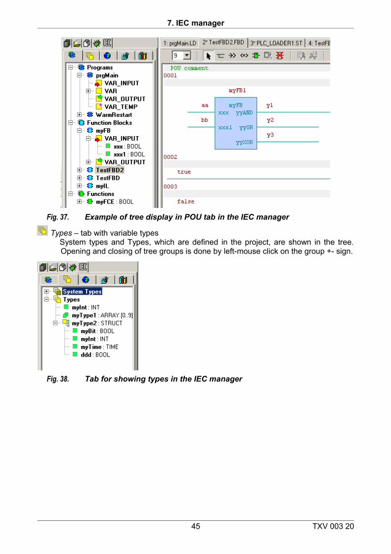
POU – tab with rules of POUs Programs, function blocks and functions are shown in a tree. Their rules are defined in the project. By clicking on the groups + sign, the group is opened. If an item of the tree is selected then we can, using the local menu or hotkeys, work with this item. It is possible to open the item in an editor and do changes to it. These changes are then retroactively projected into the POU manager tree.
44 TXV 003 20
7. IEC manager
Fig. 37. Example of tree display in POU tab in the IEC manager
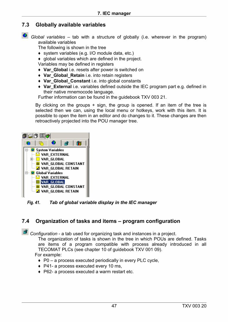
Types – tab with variable typesSystem types and Types, which are defined in the project, are shown in the tree. Opening and closing of tree groups is done by left-mouse click on the group +- sign.
Fig. 38. Tab for showing types in the IEC manager
45 TXV 003 20

Getting started with Mosaic
Fig. 39. Type declaration in the IEC manager1. Variable name – pink colour indicates unapproved name. A different one must be
chosen.2 Variable types – a variable type is determined by selecting it from the list. 3. Add following - ads following declaration with predefined settings or the OK button
closes the dialog.
Fig. 40. Structure type declaration in IEC manager1. Variable name – pink colour indicates unapproved name. A different one must be
chosen.2 Variable types – a variable type is determined by selecting it from the list. It is possible
to add items via a button (3.) if it is a structure3. Add item - adds items into the structure or the OK button closes the dialog.
46 TXV 003 20
7. IEC manager
7.3 Globally available variables
Global variables – tab with a structure of globally (i.e. wherever in the program) available variablesThe following is shown in the tree ♦ system variables (e.g. I/O module data, etc.)♦ global variables which are defined in the project.Variables may be defined in registers ♦ Var_Global i.e. resets after power is switched on♦ Var_Global_Retain i.e. into retain registers ♦ Var_Global_Constant i.e. into global constants ♦ Var_External i.e. variables defined outside the IEC program part e.g. defined in
their native mnemocode language.Further information can be found in the guidebook TXV 003 21.
By clicking on the groups + sign, the group is opened. If an item of the tree is selected then we can, using the local menu or hotkeys, work with this item. It is possible to open the item in an editor and do changes to it. These changes are then retroactively projected into the POU manager tree.
Fig. 41. Tab of global variable display in the IEC manager
7.4 Organization of tasks and items – program configuration
Configuration - a tab used for organizing task and instances in a project.The organization of tasks is shown in the tree in which POUs are defined. Tasks are items of a program compatible with process already introduced in all TECOMAT PLCs (see chapter 10 of guidebook TXV 001 09).
For example: ♦ P0 – a process executed periodically in every PLC cycle, ♦ P41- a process executed every 10 ms, ♦ P62- a process executed a warm restart etc.
47 TXV 003 20
Getting started with Mosaic
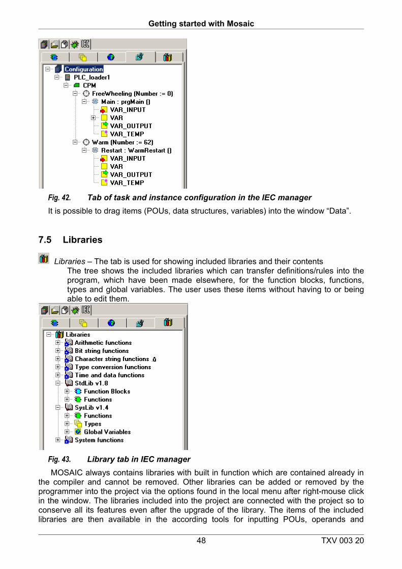
Fig. 42. Tab of task and instance configuration in the IEC managerIt is possible to drag items (POUs, data structures, variables) into the window “Data”.
7.5 Libraries
Libraries – The tab is used for showing included libraries and their contentsThe tree shows the included libraries which can transfer definitions/rules into the program, which have been made elsewhere, for the function blocks, functions, types and global variables. The user uses these items without having to or being able to edit them.
Fig. 43. Library tab in IEC manager MOSAIC always contains libraries with built in function which are contained already in
the compiler and cannot be removed. Other libraries can be added or removed by the programmer into the project via the options found in the local menu after right-mouse click in the window. The libraries included into the project are connected with the project so to conserve all its features even after the upgrade of the library. The items of the included libraries are then available in the according tools for inputting POUs, operands and
48 TXV 003 20
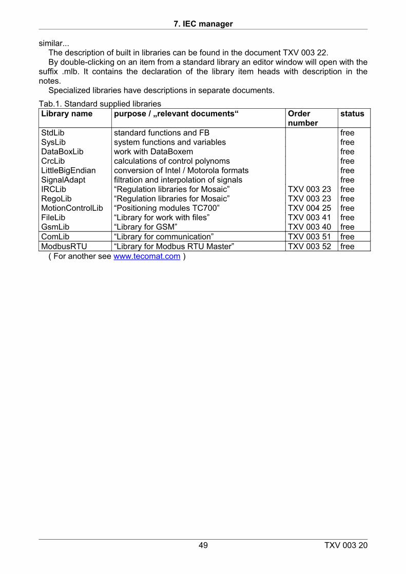
7. IEC manager
similar...The description of built in libraries can be found in the document TXV 003 22.By double-clicking on an item from a standard library an editor window will open with the
suffix .mlb. It contains the declaration of the library item heads with description in the notes.
Specialized libraries have descriptions in separate documents.Tab.1. Standard supplied libraries Library name purpose / „relevant documents“ Order
numberstatus
StdLib standard functions and FB freeSysLib system functions and variables freeDataBoxLib work with DataBoxem freeCrcLib calculations of control polynoms freeLittleBigEndian conversion of Intel / Motorola formats freeSignalAdapt filtration and interpolation of signals freeIRCLib “Regulation libraries for Mosaic” TXV 003 23 freeRegoLib “Regulation libraries for Mosaic” TXV 003 23 freeMotionControlLib “Positioning modules TC700” TXV 004 25 freeFileLib “Library for work with files” TXV 003 41 freeGsmLib “Library for GSM” TXV 003 40 freeComLib “Library for communication” TXV 003 51 freeModbusRTU “Library for Modbus RTU Master” TXV 003 52 free
( For another see www.tecomat.com )
49 TXV 003 20
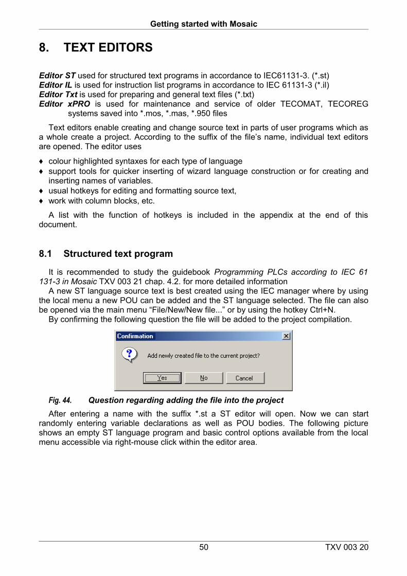
Getting started with Mosaic
8. TEXT EDITORS
Editor ST used for structured text programs in accordance to IEC61131-3. (*.st)Editor IL is used for instruction list programs in accordance to IEC 61131-3 (*.il)Editor Txt is used for preparing and general text files (*.txt)Editor xPRO is used for maintenance and service of older TECOMAT, TECOREG
systems saved into *.mos, *.mas, *.950 files
Text editors enable creating and change source text in parts of user programs which as a whole create a project. According to the suffix of the file’s name, individual text editors are opened. The editor uses
♦ colour highlighted syntaxes for each type of language ♦ support tools for quicker inserting of wizard language construction or for creating and
inserting names of variables. ♦ usual hotkeys for editing and formatting source text, ♦ work with column blocks, etc.
A list with the function of hotkeys is included in the appendix at the end of this document.
8.1 Structured text program
It is recommended to study the guidebook Programming PLCs according to IEC 61 131-3 in Mosaic TXV 003 21 chap. 4.2. for more detailed information
A new ST language source text is best created using the IEC manager where by using the local menu a new POU can be added and the ST language selected. The file can also be opened via the main menu “File/New/New file...” or by using the hotkey Ctrl+N.
By confirming the following question the file will be added to the project compilation.
Fig. 44. Question regarding adding the file into the projectAfter entering a name with the suffix *.st a ST editor will open. Now we can start
randomly entering variable declarations as well as POU bodies. The following picture shows an empty ST language program and basic control options available from the local menu accessible via right-mouse click within the editor area.
50 TXV 003 20
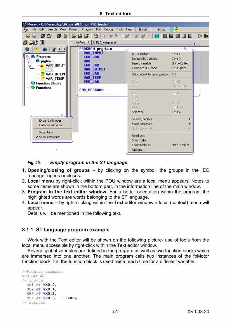
8. Text editors
Fig. 45. Empty program in the ST language. 1. Opening/closing of groups – by clicking on the symbol, the groups in the IEC
manager opens or closes.2. Local menu by right-click within the POU window are a local menu appears. Notes to
some items are shown in the bottom part, in the information line of the main window.3. Program in the text editor window. For a better orientation within the program the
highlighted words are words belonging to the ST language. 4. Local menu – by right-clicking within the Text editor window a local (context) menu will
appear.Details will be mentioned in the following text.
8.1.1 ST language program example
Work with the Text editor will be shown on the following picture- use of tools from the local menu accessible by right-click within the Text editor window.
Several global variables are defined in the program as well as two function blocks which are immersed into one another. The main program calls two instances of the fbMotor function block. I.e. the function block is used twice, each time for a different variable.
//Program example:VAR_GLOBAL// inputs SB1 AT %X0.0, SB2 AT %X0.1, SB3 AT %X0.2, SB4 AT %X0.3 : BOOL;// outputs
51 TXV 003 20
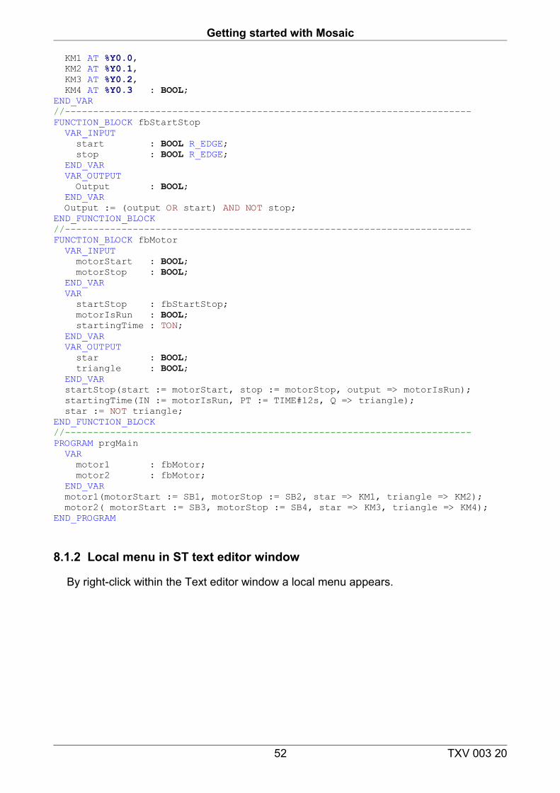
Getting started with Mosaic
KM1 AT %Y0.0, KM2 AT %Y0.1, KM3 AT %Y0.2, KM4 AT %Y0.3 : BOOL;END_VAR//------------------------------------------------------------------------FUNCTION_BLOCK fbStartStop VAR_INPUT start : BOOL R_EDGE; stop : BOOL R_EDGE; END_VAR VAR_OUTPUT Output : BOOL; END_VAR Output := (output OR start) AND NOT stop;END_FUNCTION_BLOCK//------------------------------------------------------------------------FUNCTION_BLOCK fbMotor VAR_INPUT motorStart : BOOL; motorStop : BOOL; END_VAR VAR startStop : fbStartStop; motorIsRun : BOOL; startingTime : TON; END_VAR VAR_OUTPUT star : BOOL; triangle : BOOL; END_VAR startStop(start := motorStart, stop := motorStop, output => motorIsRun); startingTime(IN := motorIsRun, PT := TIME#12s, Q => triangle); star := NOT triangle;END_FUNCTION_BLOCK//------------------------------------------------------------------------PROGRAM prgMain VAR motor1 : fbMotor; motor2 : fbMotor; END_VAR motor1(motorStart := SB1, motorStop := SB2, star => KM1, triangle => KM2); motor2( motorStart := SB3, motorStop := SB4, star => KM3, triangle => KM4);END_PROGRAM
8.1.2 Local menu in ST text editor window
By right-click within the Text editor window a local menu appears.
52 TXV 003 20
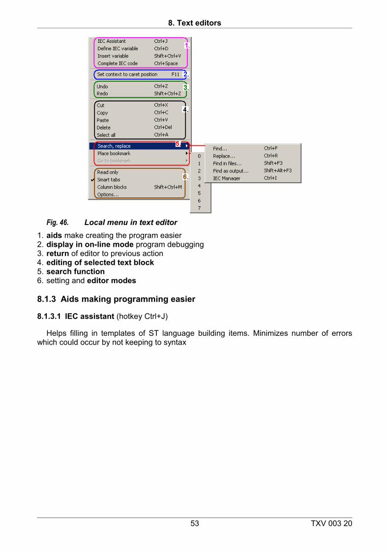
8. Text editors
Fig. 46. Local menu in text editor1. aids make creating the program easier2. display in on-line mode program debugging3. return of editor to previous action4. editing of selected text block5. search function6. setting and editor modes
8.1.3 Aids making programming easier
8.1.3.1 IEC assistant (hotkey Ctrl+J)
Helps filling in templates of ST language building items. Minimizes number of errors which could occur by not keeping to syntax
53 TXV 003 20
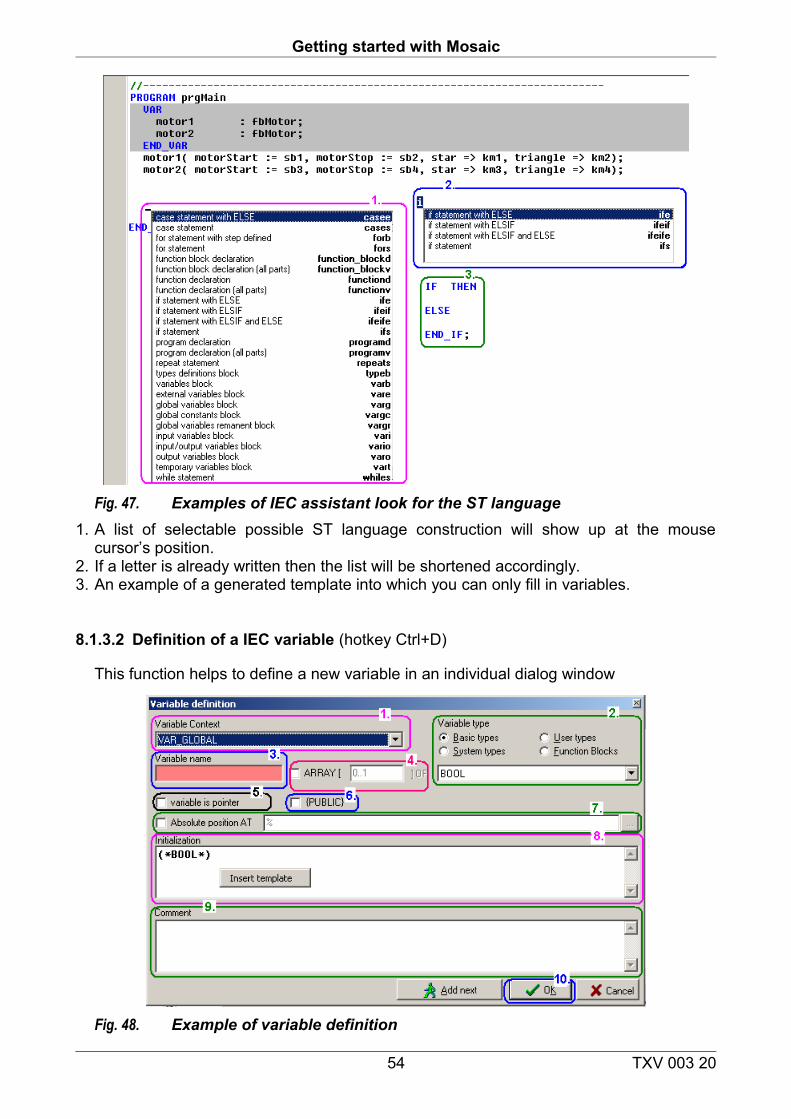
Getting started with Mosaic
Fig. 47. Examples of IEC assistant look for the ST language1. A list of selectable possible ST language construction will show up at the mouse
cursor’s position.2. If a letter is already written then the list will be shortened accordingly.3. An example of a generated template into which you can only fill in variables.
8.1.3.2 Definition of a IEC variable (hotkey Ctrl+D)
This function helps to define a new variable in an individual dialog window
Fig. 48. Example of variable definition
54 TXV 003 20
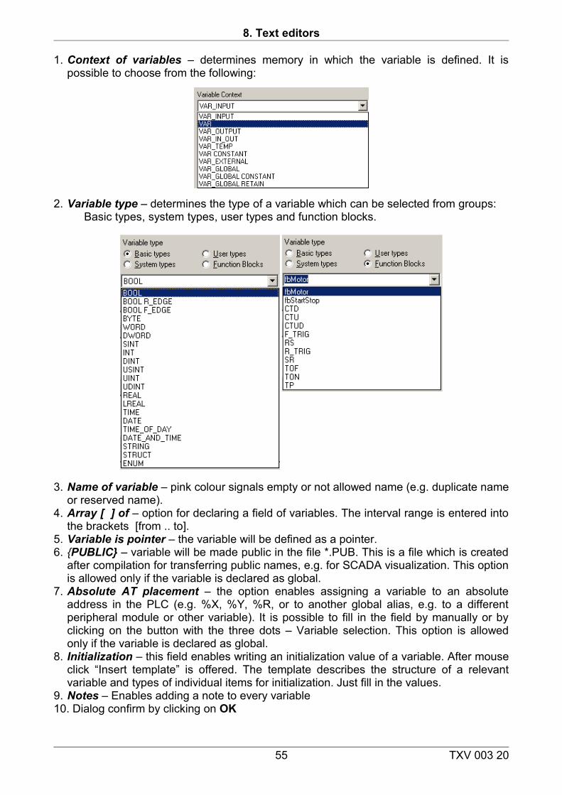
8. Text editors
1. Context of variables – determines memory in which the variable is defined. It is possible to choose from the following:
2. Variable type – determines the type of a variable which can be selected from groups:Basic types, system types, user types and function blocks.
3. Name of variable – pink colour signals empty or not allowed name (e.g. duplicate name or reserved name).
4. Array [ ] of – option for declaring a field of variables. The interval range is entered into the brackets [from .. to].
5. Variable is pointer – the variable will be defined as a pointer.6. {PUBLIC} – variable will be made public in the file *.PUB. This is a file which is created
after compilation for transferring public names, e.g. for SCADA visualization. This option is allowed only if the variable is declared as global.
7. Absolute AT placement – the option enables assigning a variable to an absolute address in the PLC (e.g. %X, %Y, %R, or to another global alias, e.g. to a different peripheral module or other variable). It is possible to fill in the field by manually or by clicking on the button with the three dots – Variable selection. This option is allowed only if the variable is declared as global.
8. Initialization – this field enables writing an initialization value of a variable. After mouse click “Insert template” is offered. The template describes the structure of a relevant variable and types of individual items for initialization. Just fill in the values.
9. Notes – Enables adding a note to every variable10. Dialog confirm by clicking on OK
55 TXV 003 20
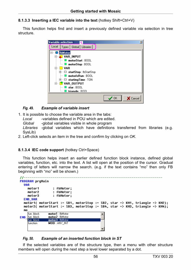
Getting started with Mosaic
8.1.3.3 Inserting a IEC variable into the text (hotkey Shift+Ctrl+V)
This function helps find and insert a previously defined variable via selection in tree structure.
Fig. 49. Example of variable insert1. It is possible to choose the variable area in the tabs:
Local -variables defined in POU which are edited.Global -global variables visible in whole programLibraries -global variables which have definitions transferred from libraries (e.g. SysLib)
2. Left-click selects an item in the tree and confirm by clicking on OK.
8.1.3.4 IEC code support (hotkey Ctrl+Space)
This function helps insert an earlier defined function block instance, defined global variables, function, etc. into the text. A list will open at the position of the cursor. Gradual entering of letters will narrow the search. (e.g. if the text contains “mo” then only FB beginning with “mo” will be shown.)
Fig. 50. Example of an inserted function block in STIf the selected variables are of the structure type, then a menu with other structure
members will open during the next step a level lower separated by a dot.
56 TXV 003 20
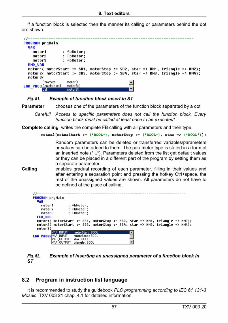
8. Text editors
If a function block is selected then the manner its calling or parameters behind the dot are shown.
Fig. 51. Example of function block insert in STParameter chooses one of the parameters of the function block separated by a dot
Careful! Access to specific parameters does not call the function block. Every function block must be called at least once to be executed!
Complete calling writes the complete FB calling with all parameters and their type.motor2(motorStart := (*BOOL*), motorStop := (*BOOL*), star => (*BOOL*));
Random parameters can be deleted or transferred variables/parameters or values can be added to them. The parameter type is stated in a form of an inserted note (*...*). Parameters deleted from the list get default values or they can be placed in a different part of the program by setting them as a separate parameter.
Calling enables gradual recording of each parameter, filling in their values and after entering a separation point and pressing the hotkey Ctrl+space, the rest of the unassigned values are shown. All parameters do not have to be defined at the place of calling.
Fig. 52. Example of inserting an unassigned parameter of a function block in ST
8.2 Program in instruction list language
It is recommended to study the guidebook PLC programming according to IEC 61 131-3 Mosaic TXV 003 21 chap. 4.1 for detailed information.
57 TXV 003 20
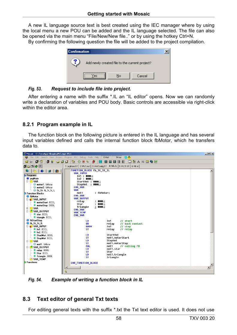
Getting started with Mosaic
A new IL language source text is best created using the IEC manager where by using the local menu a new POU can be added and the IL language selected. The file can also be opened via the main menu “File/New/New file..” or by using the hotkey Ctrl+N.
By confirming the following question the file will be added to the project compilation.
Fig. 53. Request to include file into project. After entering a name with the suffix *.IL an “IL editor” opens. Now we can randomly
write a declaration of variables and POU body. Basic controls are accessible via right-click within the editor area.
8.2.1 Program example in IL
The function block on the following picture is entered in the IL language and has several input variables defined and calls the internal function block fbMotor, which he transfers data to.
Fig. 54. Example of writing a function block in IL
8.3 Text editor of general Txt texts
For editing general texts with the suffix *.txt the Txt text editor is used. It does not use
58 TXV 003 20
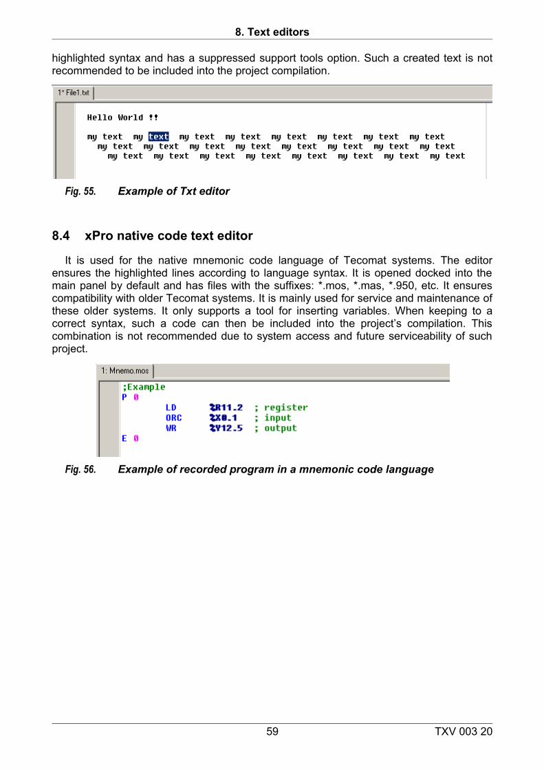
8. Text editors
highlighted syntax and has a suppressed support tools option. Such a created text is not recommended to be included into the project compilation.
Fig. 55. Example of Txt editor
8.4 xPro native code text editor
It is used for the native mnemonic code language of Tecomat systems. The editor ensures the highlighted lines according to language syntax. It is opened docked into the main panel by default and has files with the suffixes: *.mos, *.mas, *.950, etc. It ensures compatibility with older Tecomat systems. It is mainly used for service and maintenance of these older systems. It only supports a tool for inserting variables. When keeping to a correct syntax, such a code can then be included into the project’s compilation. This combination is not recommended due to system access and future serviceability of such project.
Fig. 56. Example of recorded program in a mnemonic code language
59 TXV 003 20
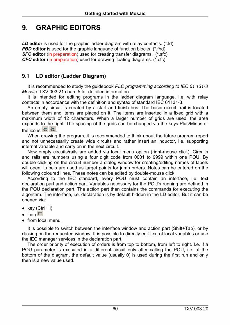
Getting started with Mosaic
9. GRAPHIC EDITORS
LD editor is used for the graphic ladder diagram with relay contacts. (*.ld)FBD editor is used for the graphic language of function blocks. (*.fbd)SFC editor (in preparation) used for creating transfer diagrams. (*.sfc)CFC editor (in preparation) used for drawing floating diagrams. (*.cfc)
9.1 LD editor (Ladder Diagram)
It is recommended to study the guidebook PLC programming according to IEC 61 131-3 Mosaic TXV 003 21 chap. 5 for detailed information.
It is intended for editing programs in the ladder diagram language, i.e. with relay contacts in accordance with the definition and syntax of standard IEC 61131-3.
An empty circuit is created by a start and finish bus. The basic circuit rail is located between them and items are placed on it. The items are inserted in a fixed grid with a maximum width of 12 characters. When a larger number of grids are used, the area expands to the right. The spacing of the grids can be changed via the keys Plus/Minus or the icons .
When drawing the program, it is recommended to think about the future program report and not unnecessarily create wide circuits and rather insert an inductor, i.e. supporting internal variable and carry on in the next circuit.
New empty circuits/rails are added via local menu option (right-mouse click). Circuits and rails are numbers using a four digit code from 0001 to 9999 within one POU. By double-clicking on the circuit number a dialog window for creating/editing names of labels will open. Labels are used as target points for jump orders. Notes can be entered on the following coloured lines. These notes can be edited by double-mouse click.
According to the IEC standard, every POU must contain an interface, i.e. text declaration part and action part. Variables necessary for the POU’s running are defined in the POU declaration part. The action part then contains the commands for executing the algorithm. The interface, i.e. declaration is by default hidden in the LD editor. But it can be opened via:
♦ key (Ctrl+H) ♦ icon ,♦ from local menu.
It is possible to switch between the interface window and action part (Shift+Tab), or by clicking on the requested window. It is possible to directly edit text of local variables or use the IEC manager services in the declaration part.
The order priority of execution of orders is from top to bottom, from left to right. I.e. if a POU parameter is executed in a different circuit only after calling the POU, i.e. at the bottom of the diagram, the default value (usually 0) is used during the first run and only then is a new value used.
60 TXV 003 20
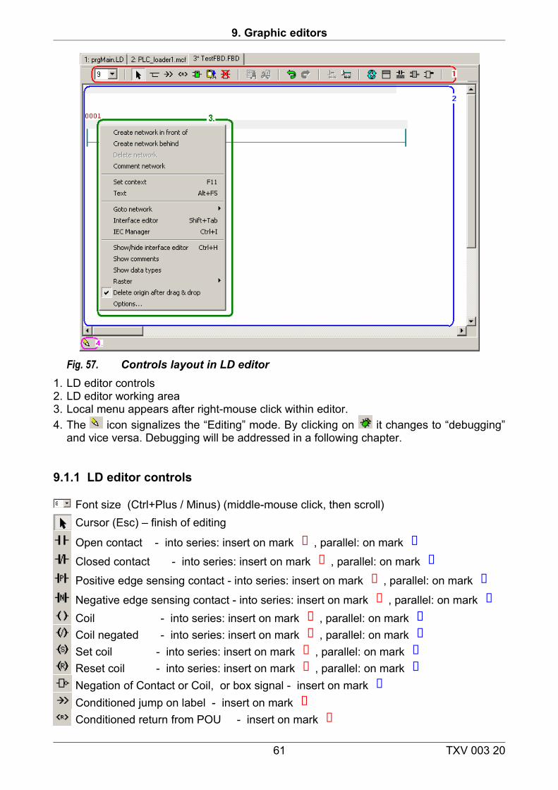
9. Graphic editors
Fig. 57. Controls layout in LD editor1. LD editor controls2. LD editor working area3. Local menu appears after right-mouse click within editor.4. The icon signalizes the “Editing” mode. By clicking on it changes to “debugging”
and vice versa. Debugging will be addressed in a following chapter.
9.1.1 LD editor controls
Font size (Ctrl+Plus / Minus) (middle-mouse click, then scroll)Cursor (Esc) – finish of editing
Open contact - into series: insert on mark , parallel: on mark
Closed contact - into series: insert on mark , parallel: on mark
Positive edge sensing contact - into series: insert on mark , parallel: on mark
Negative edge sensing contact - into series: insert on mark , parallel: on mark Coil - into series: insert on mark , parallel: on mark Coil negated - into series: insert on mark , parallel: on mark Set coil - into series: insert on mark , parallel: on mark Reset coil - into series: insert on mark , parallel: on mark Negation of Contact or Coil, or box signal - insert on mark Conditioned jump on label - insert on mark Conditioned return from POU - insert on mark
61 TXV 003 20
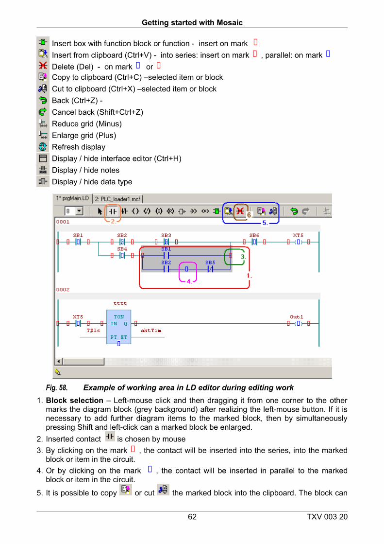
Getting started with Mosaic
Insert box with function block or function - insert on mark Insert from clipboard (Ctrl+V) - into series: insert on mark , parallel: on markDelete (Del) - on mark orCopy to clipboard (Ctrl+C) –selected item or blockCut to clipboard (Ctrl+X) –selected item or block Back (Ctrl+Z) - Cancel back (Shift+Ctrl+Z)Reduce grid (Minus)Enlarge grid (Plus)Refresh displayDisplay / hide interface editor (Ctrl+H) Display / hide notesDisplay / hide data type
Fig. 58. Example of working area in LD editor during editing work1. Block selection – Left-mouse click and then dragging it from one corner to the other
marks the diagram block (grey background) after realizing the left-mouse button. If it is necessary to add further diagram items to the marked block, then by simultaneously pressing Shift and left-click can a marked block be enlarged.
2. Inserted contact is chosen by mouse3. By clicking on the mark , the contact will be inserted into the series, into the marked
block or item in the circuit.4. Or by clicking on the mark , the contact will be inserted in parallel to the marked
block or item in the circuit.
5. It is possible to copy or cut the marked block into the clipboard. The block can
62 TXV 003 20
9. Graphic editors
then by inserted from the clipboard into a random coloured mark.
6. Using the Del icon , the items marked with the marks , or can be deleted.7. Left-click and dragging and dropping the marked block to a random position marked by
the marks , or are possible. A block can be dragged and dropped into a different circuit. It is possible to setup in the local menu whether the dragged block will be relocated or copied.
9.1.2 Editing contact name - operand
Fig. 59. Example of dialog window for editing operands1. If a new contact is inserted a dialog window will open for entering the name of the
operand. This dialog is also opened upon double-click on an already existing operand.2. It is possible to directly write in the name. If this name is not yet defined then another
dialog window opens for defining the new variable.
3. By pressing the button a dialog window will open for selecting an already defined name.
9.1.3 Inserting or editing a box in LD
A box is a graphic item of a diagram visualizing the POU. Generally every box with a function or function block has signals with input variables or constants attached to its input parameters.
A box can also have output variables or input parameters of another box connected to its output parameters.
A box with a function block has a light blue colour a block with a function has a light green colour.
63 TXV 003 20
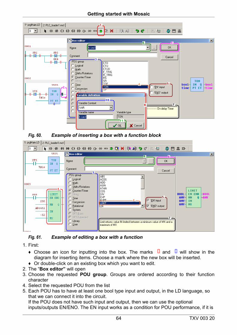
Getting started with Mosaic
Fig. 60. Example of inserting a box with a function block
Fig. 61. Example of editing a box with a function1. First:
♦ Choose an icon for inputting into the box. The marks and will show in the diagram for inserting items. Choose a mark where the new box will be inserted.
♦ Or double-click on an existing box which you want to edit. 2. The “Box editor” will open3. Choose the requested POU group. Groups are ordered according to their function
character4. Select the requested POU from the list5. Each POU has to have at least one bool type input and output, in the LD language, so
that we can connect it into the circuit.If the POU does not have such input and output, then we can use the optional inputs/outputs EN/ENO. The EN input works as a condition for POU performance, if it is
64 TXV 003 20
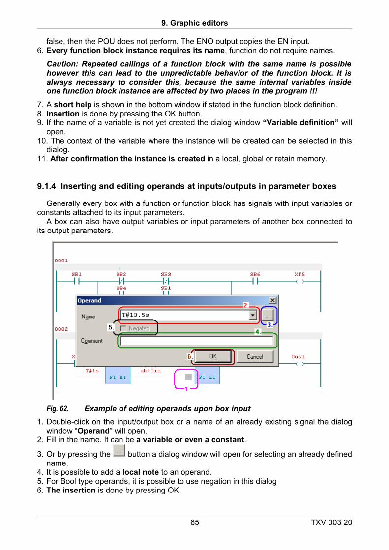
9. Graphic editors
false, then the POU does not perform. The ENO output copies the EN input.6. Every function block instance requires its name, function do not require names.
Caution: Repeated callings of a function block with the same name is possible however this can lead to the unpredictable behavior of the function block. It is always necessary to consider this, because the same internal variables inside one function block instance are affected by two places in the program !!!
7. A short help is shown in the bottom window if stated in the function block definition.8. Insertion is done by pressing the OK button.9. If the name of a variable is not yet created the dialog window “Variable definition” will
open.10. The context of the variable where the instance will be created can be selected in this
dialog.11. After confirmation the instance is created in a local, global or retain memory.
9.1.4 Inserting and editing operands at inputs/outputs in parameter boxes
Generally every box with a function or function block has signals with input variables or constants attached to its input parameters.
A box can also have output variables or input parameters of another box connected to its output parameters.
Fig. 62. Example of editing operands upon box input1. Double-click on the input/output box or a name of an already existing signal the dialog
window “Operand” will open.2. Fill in the name. It can be a variable or even a constant.
3. Or by pressing the button a dialog window will open for selecting an already defined name.
4. It is possible to add a local note to an operand.5. For Bool type operands, it is possible to use negation in this dialog6. The insertion is done by pressing OK.
65 TXV 003 20
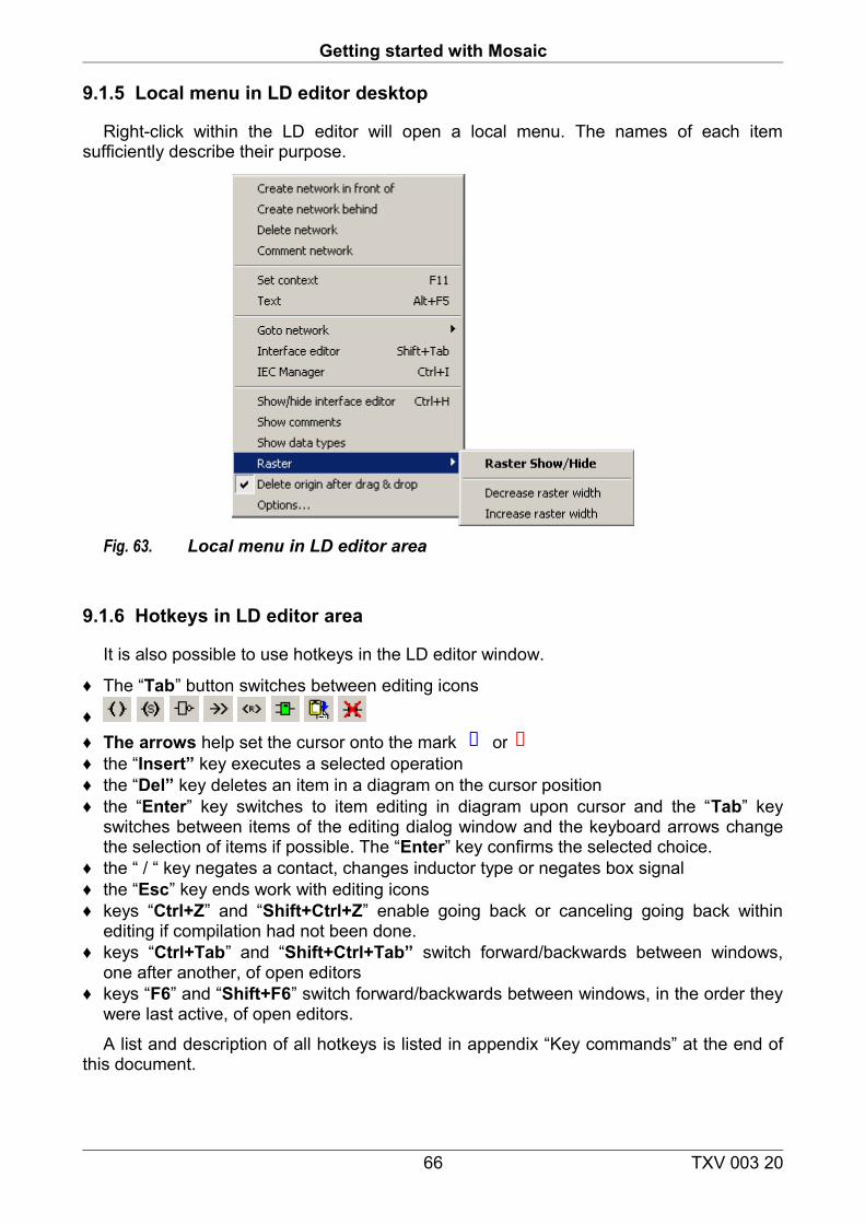
Getting started with Mosaic
9.1.5 Local menu in LD editor desktop
Right-click within the LD editor will open a local menu. The names of each item sufficiently describe their purpose.
Fig. 63. Local menu in LD editor area
9.1.6 Hotkeys in LD editor area
It is also possible to use hotkeys in the LD editor window.
♦ The “Tab” button switches between editing icons
♦ ♦ The arrows help set the cursor onto the mark or ♦ the “Insert” key executes a selected operation♦ the “Del” key deletes an item in a diagram on the cursor position♦ the “Enter” key switches to item editing in diagram upon cursor and the “Tab” key
switches between items of the editing dialog window and the keyboard arrows change the selection of items if possible. The “Enter” key confirms the selected choice.
♦ the “ / “ key negates a contact, changes inductor type or negates box signal♦ the “Esc” key ends work with editing icons♦ keys “Ctrl+Z” and “Shift+Ctrl+Z” enable going back or canceling going back within
editing if compilation had not been done.♦ keys “Ctrl+Tab” and “Shift+Ctrl+Tab” switch forward/backwards between windows,
one after another, of open editors♦ keys “F6” and “Shift+F6” switch forward/backwards between windows, in the order they
were last active, of open editors.
A list and description of all hotkeys is listed in appendix “Key commands” at the end of this document.
66 TXV 003 20
9. Graphic editors
9.2 FBD editor (Function Block Diagram)
It is recommended to study the guidebook PLC programming according to IEC 61 131-3 Mosaic TXV 003 21 chap. 5 for detailed information.
It is intended for editing programs in the function block language, in accordance with the definition and syntax of standard IEC 61131-3.
An empty circuit is created by a start line on which circuit items are gradually placed, i.e. names of signals and function blocks (FB).
The items are inserted in a fixed grid with a maximum width of 12 characters. When a larger number of grids is used, the area expands to the right. The spacing of the grids can be changed via the keys Plus/Minus or the icons .
When drawing the program, it is recommended to think about the future program report and not unnecessarily create wide circuits and rather insert a supporting internal variable and carry on in the next circuit.
New empty circuits are added via local menu option. Circuits and rails are numbered using a four digit code from 0001 to 9999 within one POU. By double-clicking on the circuit number a dialog window for editing names of labels will open. Labels are used as target points for jump orders. Notes can be entered on the following coloured lines. These notes can be edited by double-mouse click.
According to the IEC standard, every POU must contain an interface, i.e. text declaration part and action part. The interface in the LD editor is by default hidden and can be opened using the hotkey (Ctrl+H) or the icon , or via the local menu. It is possible to directly edit text of local variables in the declaration part using the benefits of the IEC manager services.
The action part then contains own commands for the execution of the requested algorithm. It is possible to switch between the interface window and action part (Shift+Tab), or by clicking on the requested window. The order priority of execution of orders is from top to bottom, from left to right. I.e. if a POU parameter is executed in a different circuit only after calling the POU, i.e. at the bottom of the diagram, the default value (usually 0) is used during the first run and only then is a new value used.
67 TXV 003 20
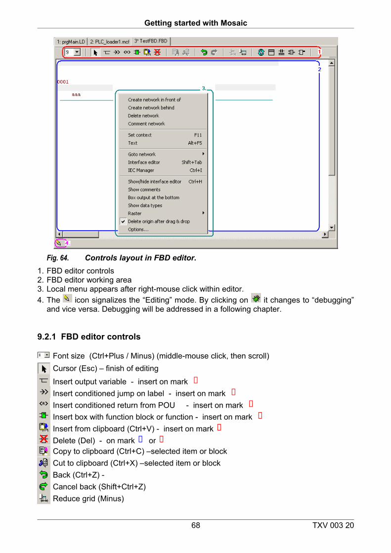
Getting started with Mosaic
Fig. 64. Controls layout in FBD editor.1. FBD editor controls2. FBD editor working area3. Local menu appears after right-mouse click within editor.4. The icon signalizes the “Editing” mode. By clicking on it changes to “debugging”
and vice versa. Debugging will be addressed in a following chapter.
9.2.1 FBD editor controls
Font size (Ctrl+Plus / Minus) (middle-mouse click, then scroll)Cursor (Esc) – finish of editing
Insert output variable - insert on mark Insert conditioned jump on label - insert on mark Insert conditioned return from POU - insert on mark Insert box with function block or function - insert on mark Insert from clipboard (Ctrl+V) - insert on markDelete (Del) - on mark orCopy to clipboard (Ctrl+C) –selected item or blockCut to clipboard (Ctrl+X) –selected item or block Back (Ctrl+Z) - Cancel back (Shift+Ctrl+Z)Reduce grid (Minus)
68 TXV 003 20
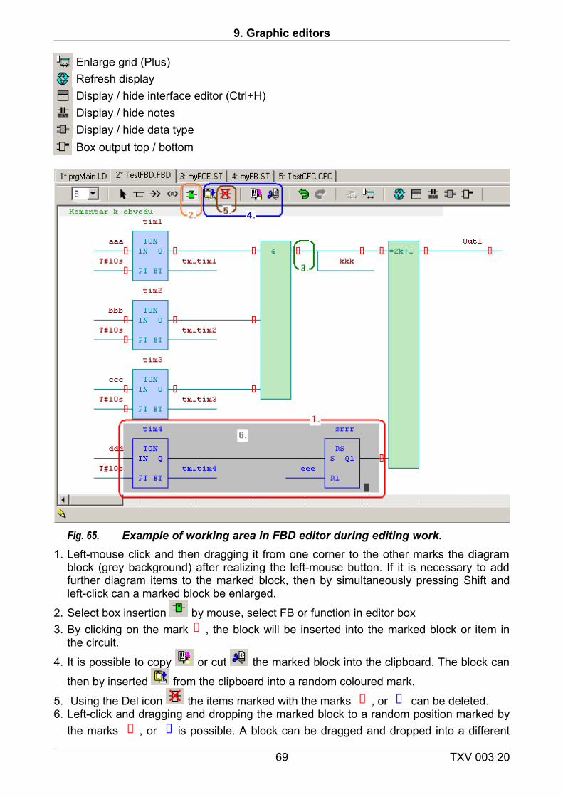
9. Graphic editors
Enlarge grid (Plus)Refresh displayDisplay / hide interface editor (Ctrl+H) Display / hide notesDisplay / hide data typeBox output top / bottom
Fig. 65. Example of working area in FBD editor during editing work. 1. Left-mouse click and then dragging it from one corner to the other marks the diagram
block (grey background) after realizing the left-mouse button. If it is necessary to add further diagram items to the marked block, then by simultaneously pressing Shift and left-click can a marked block be enlarged.
2. Select box insertion by mouse, select FB or function in editor box3. By clicking on the mark , the block will be inserted into the marked block or item in
the circuit.
4. It is possible to copy or cut the marked block into the clipboard. The block can
then by inserted from the clipboard into a random coloured mark.
5. Using the Del icon the items marked with the marks , or can be deleted.6. Left-click and dragging and dropping the marked block to a random position marked by
the marks , or is possible. A block can be dragged and dropped into a different
69 TXV 003 20
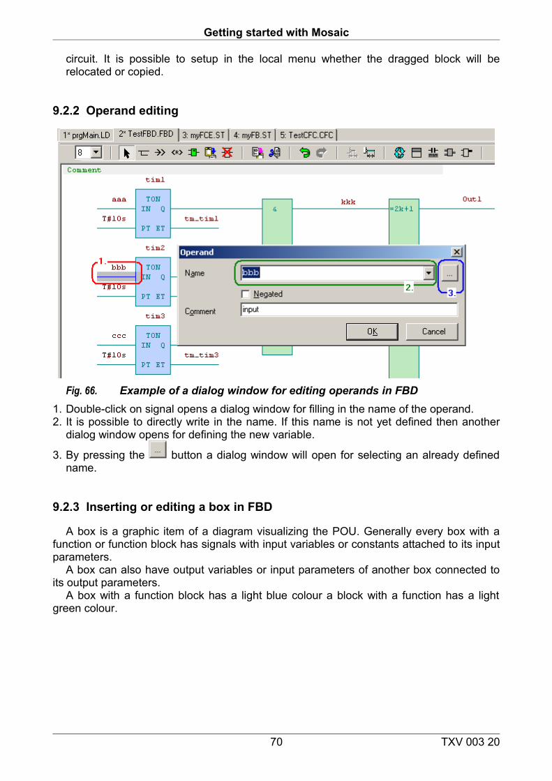
Getting started with Mosaic
circuit. It is possible to setup in the local menu whether the dragged block will be relocated or copied.
9.2.2 Operand editing
Fig. 66. Example of a dialog window for editing operands in FBD1. Double-click on signal opens a dialog window for filling in the name of the operand.2. It is possible to directly write in the name. If this name is not yet defined then another
dialog window opens for defining the new variable.
3. By pressing the button a dialog window will open for selecting an already defined name.
9.2.3 Inserting or editing a box in FBD
A box is a graphic item of a diagram visualizing the POU. Generally every box with a function or function block has signals with input variables or constants attached to its input parameters.
A box can also have output variables or input parameters of another box connected to its output parameters.
A box with a function block has a light blue colour a block with a function has a light green colour.
70 TXV 003 20
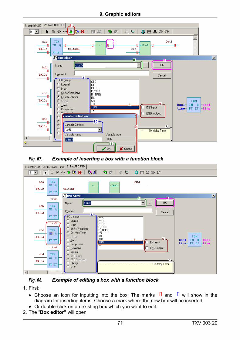
9. Graphic editors
Fig. 67. Example of inserting a box with a function block
Fig. 68. Example of editing a box with a function block1. First:
♦ Choose an icon for inputting into the box. The marks and will show in the diagram for inserting items. Choose a mark where the new box will be inserted.
♦ Or double-click on an existing box which you want to edit. 2. The “Box editor” will open
71 TXV 003 20
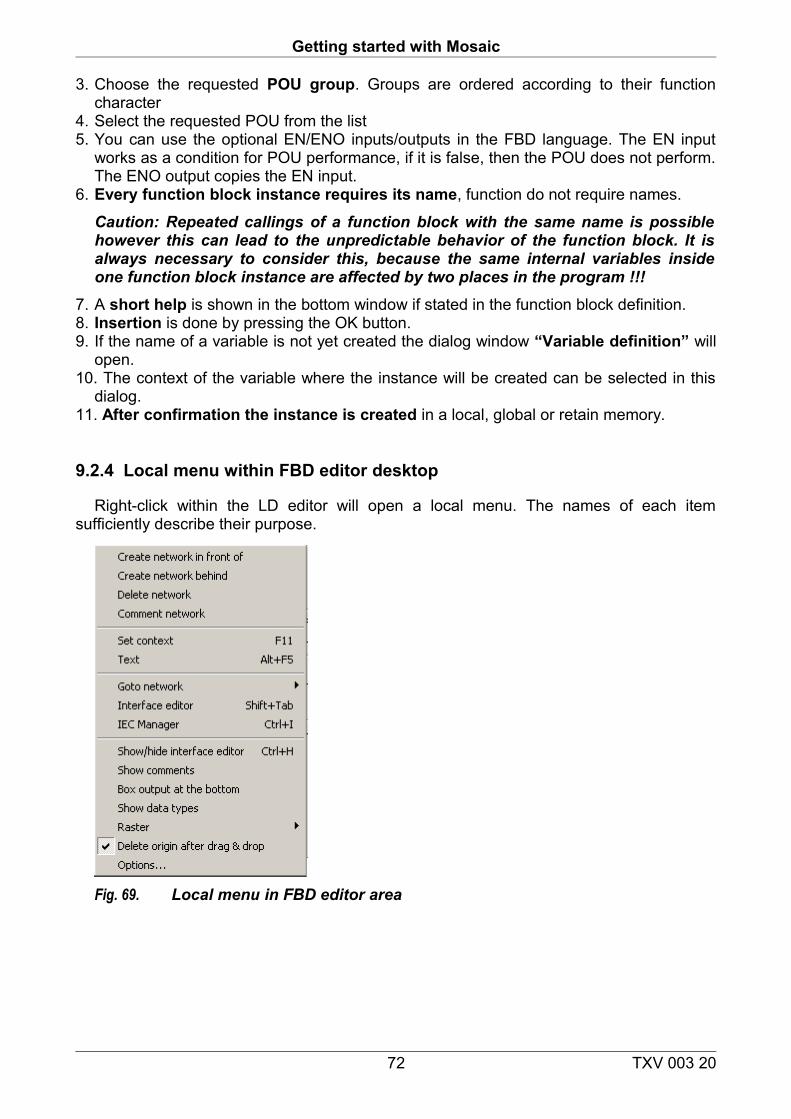
Getting started with Mosaic
3. Choose the requested POU group. Groups are ordered according to their function character
4. Select the requested POU from the list5. You can use the optional EN/ENO inputs/outputs in the FBD language. The EN input
works as a condition for POU performance, if it is false, then the POU does not perform. The ENO output copies the EN input.
6. Every function block instance requires its name, function do not require names.
Caution: Repeated callings of a function block with the same name is possible however this can lead to the unpredictable behavior of the function block. It is always necessary to consider this, because the same internal variables inside one function block instance are affected by two places in the program !!!
7. A short help is shown in the bottom window if stated in the function block definition.8. Insertion is done by pressing the OK button.9. If the name of a variable is not yet created the dialog window “Variable definition” will
open.10. The context of the variable where the instance will be created can be selected in this
dialog.11. After confirmation the instance is created in a local, global or retain memory.
9.2.4 Local menu within FBD editor desktop
Right-click within the LD editor will open a local menu. The names of each item sufficiently describe their purpose.
Fig. 69. Local menu in FBD editor area
72 TXV 003 20
9. Graphic editors
9.2.5 Hotkeys in FBD editor area
It is also possible to use hotkeys in the FBD editor window.
♦ The “Tab” button switches between editing icons
♦ ♦ The arrows help set the cursor onto the mark ♦ the “Insert” key executes a selected operation♦ the “Del” key deletes an item in a diagram on the cursor position♦ the “Enter” key switches to item editing in diagram upon cursor and the “Tab” key
switches between items of the editing dialog window and the keyboard arrows change the selection of items if possible. The “Enter” key confirms the selected choice.
♦ the “ / “ key negates a contact, changes inductor type or negates box signal♦ the “Esc” key ends work with editing icons♦ keys “Ctrl+Z” and “Shift+Ctrl+Z” enable going back or canceling going back within
editing if compilation had not been done.♦ keys “Ctrl+Tab” and “Shift+Ctrl+Tab” switch forward/backwards between windows,
one after another, of open editors♦ keys “F6” and “Shift+F6” switch forward/backwards between windows, in the order they
were last active, of open editors.
A list and description of all hotkeys is listed in appendix “Key commands” at the end of this document.
9.3 SFC editor (in preparation) (Sequential Function Chart)
Creating Sequential Function Charts.
9.4 Editor CFC (in preparation) (Continuous Flow Chart)
Graphic visualization of Continuous Flow Charts.
73 TXV 003 20
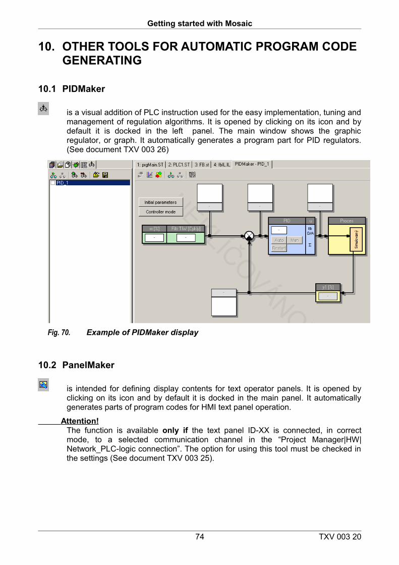
Getting started with Mosaic
10. OTHER TOOLS FOR AUTOMATIC PROGRAM CODE GENERATING
10.1 PIDMaker
is a visual addition of PLC instruction used for the easy implementation, tuning and management of regulation algorithms. It is opened by clicking on its icon and by default it is docked in the left panel. The main window shows the graphic regulator, or graph. It automatically generates a program part for PID regulators. (See document TXV 003 26)
Fig. 70. Example of PIDMaker display
10.2 PanelMaker
is intended for defining display contents for text operator panels. It is opened by clicking on its icon and by default it is docked in the main panel. It automatically generates parts of program codes for HMI text panel operation.
Attention! The function is available only if the text panel ID-XX is connected, in correct mode, to a selected communication channel in the “Project Manager|HW|Network_PLC-logic connection”. The option for using this tool must be checked in the settings (See document TXV 003 25).
74 TXV 003 20
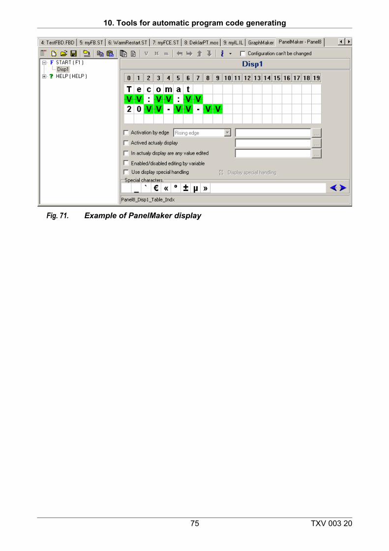
10. Tools for automatic program code generating
Fig. 71. Example of PanelMaker display
75 TXV 003 20
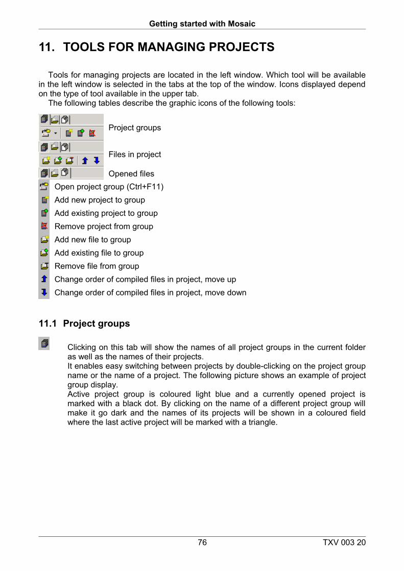
Getting started with Mosaic
11. TOOLS FOR MANAGING PROJECTS
Tools for managing projects are located in the left window. Which tool will be available in the left window is selected in the tabs at the top of the window. Icons displayed depend on the type of tool available in the upper tab.
The following tables describe the graphic icons of the following tools:
Project groups
Files in project
Opened filesOpen project group (Ctrl+F11)Add new project to groupAdd existing project to groupRemove project from groupAdd new file to groupAdd existing file to groupRemove file from groupChange order of compiled files in project, move upChange order of compiled files in project, move down
11.1 Project groups
Clicking on this tab will show the names of all project groups in the current folder as well as the names of their projects. It enables easy switching between projects by double-clicking on the project group name or the name of a project. The following picture shows an example of project group display. Active project group is coloured light blue and a currently opened project is marked with a black dot. By clicking on the name of a different project group will make it go dark and the names of its projects will be shown in a coloured field where the last active project will be marked with a triangle.
76 TXV 003 20
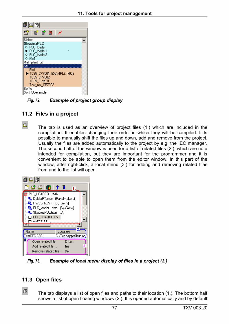
11. Tools for project management
Fig. 72. Example of project group display
11.2 Files in a project
The tab is used as an overview of project files (1.) which are included in the compilation. It enables changing their order in which they will be compiled. It Is possible to manually shift the files up and down, add and remove from the project. Usually the files are added automatically to the project by e.g. the IEC manager. The second half of the window is used for a list of related files (2.), which are note intended for compilation, but they are important for the programmer and it is convenient to be able to open them from the editor window. In this part of the window, after right-click, a local menu (3.) for adding and removing related files from and to the list will open.
Fig. 73. Example of local menu display of files in a project (3.)
11.3 Open files
The tab displays a list of open files and paths to their location (1.). The bottom half shows a list of open floating windows (2.). It is opened automatically and by default
77 TXV 003 20
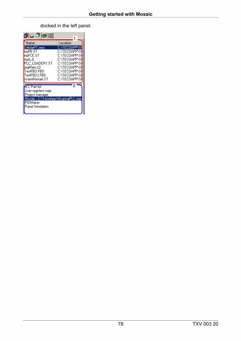
Getting started with Mosaic
docked in the left panel.
78 TXV 003 20
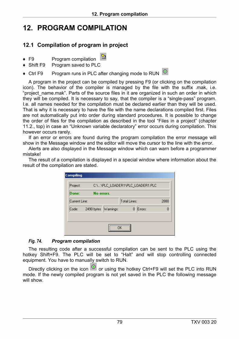
12. Program compilation
12. PROGRAM COMPILATION
12.1 Compilation of program in project
♦ F9 Program compilation ♦ Shift F9 Program saved to PLC
♦ Ctrl F9 Program runs in PLC after changing mode to RUN
A program in the project can be compiled by pressing F9 (or clicking on the compilation icon). The behavior of the compiler is managed by the file with the suffix .mak, i.e. “project_name.mak”. Parts of the source files in it are organized in such an order in which they will be compiled. It is necessary to say, that the compiler is a “single-pass” program. I.e. all names needed for the compilation must be declared earlier than they will be used. That is why it is necessary to have the file with the name declarations compiled first. Files are not automatically put into order during standard procedures. It is possible to change the order of files for the compilation as described in the tool “Files in a project” (chapter 11.2., top) in case an “Unknown variable declaratory” error occurs during compilation. This however occurs rarely.
If an error or errors are found during the program compilation the error message will show in the Message window and the editor will move the cursor to the line with the error.
Alerts are also displayed in the Message window which can warn before a programmer mistake!
The result of a compilation is displayed in a special window where information about the result of the compilation are stated.
Fig. 74. Program compilationThe resulting code after a successful compilation can be sent to the PLC using the
hotkey Shift+F9. The PLC will be set to “Halt” and will stop controlling connected equipment. You have to manually switch to RUN.
Directly clicking on the icon or using the hotkey Ctrl+F9 will set the PLC into RUN mode. If the newly compiled program is not yet saved in the PLC the following message will show.
79 TXV 003 20
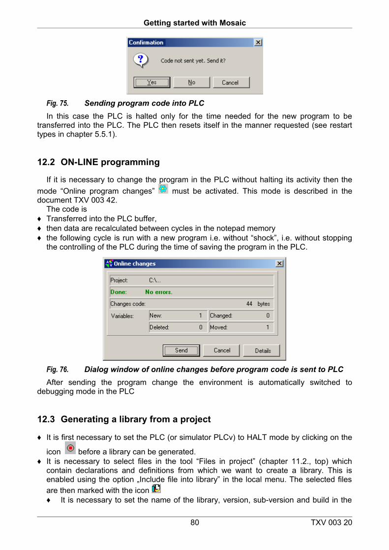
Getting started with Mosaic
Fig. 75. Sending program code into PLCIn this case the PLC is halted only for the time needed for the new program to be
transferred into the PLC. The PLC then resets itself in the manner requested (see restart types in chapter 5.5.1).
12.2 ON-LINE programming
If it is necessary to change the program in the PLC without halting its activity then the mode “Online program changes” must be activated. This mode is described in the document TXV 003 42.
The code is♦ Transferred into the PLC buffer,♦ then data are recalculated between cycles in the notepad memory♦ the following cycle is run with a new program i.e. without “shock”, i.e. without stopping
the controlling of the PLC during the time of saving the program in the PLC.
Fig. 76. Dialog window of online changes before program code is sent to PLCAfter sending the program change the environment is automatically switched to
debugging mode in the PLC
12.3 Generating a library from a project
♦ It is first necessary to set the PLC (or simulator PLCv) to HALT mode by clicking on the
icon before a library can be generated. ♦ It is necessary to select files in the tool “Files in project” (chapter 11.2., top) which
contain declarations and definitions from which we want to create a library. This is enabled using the option „Include file into library” in the local menu. The selected files are then marked with the icon ♦ It is necessary to set the name of the library, version, sub-version and build in the
80 TXV 003 20
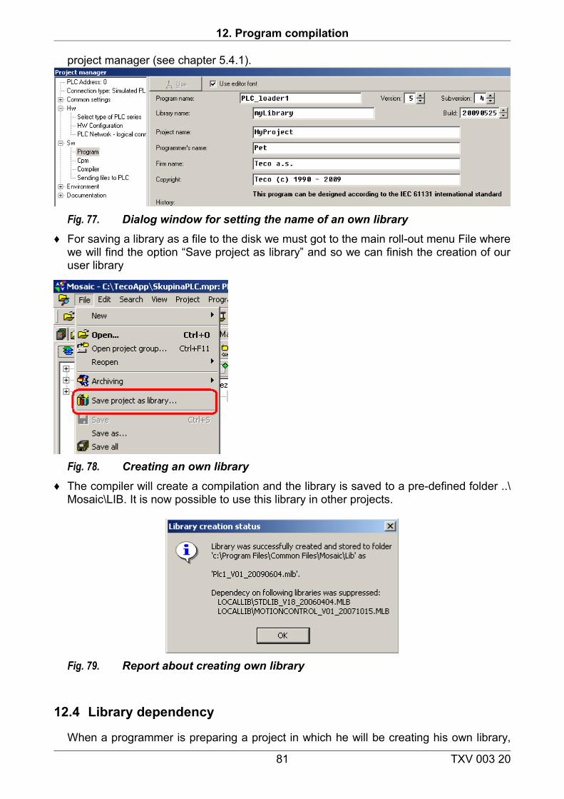
12. Program compilation
project manager (see chapter 5.4.1).
Fig. 77. Dialog window for setting the name of an own library♦ For saving a library as a file to the disk we must got to the main roll-out menu File where
we will find the option “Save project as library” and so we can finish the creation of our user library
Fig. 78. Creating an own library♦ The compiler will create a compilation and the library is saved to a pre-defined folder ..\
Mosaic\LIB. It is now possible to use this library in other projects.
Fig. 79. Report about creating own library
12.4 Library dependency
When a programmer is preparing a project in which he will be creating his own library,
81 TXV 003 20
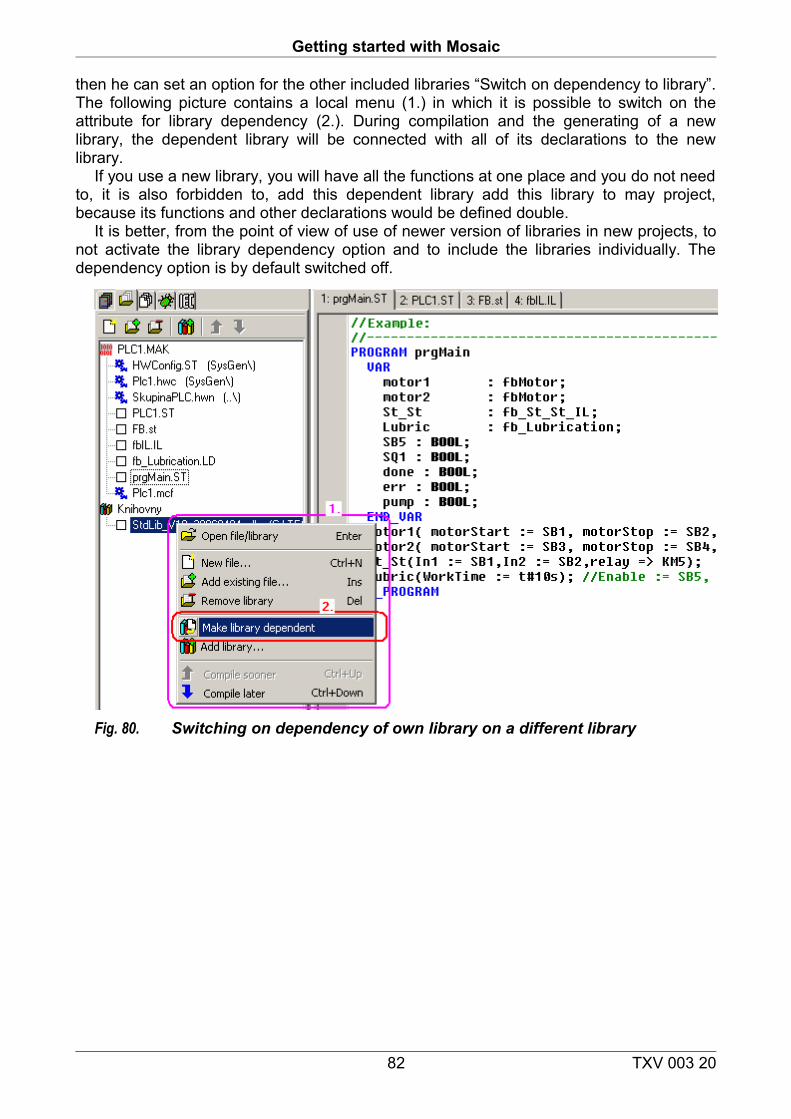
Getting started with Mosaic
then he can set an option for the other included libraries “Switch on dependency to library”. The following picture contains a local menu (1.) in which it is possible to switch on the attribute for library dependency (2.). During compilation and the generating of a new library, the dependent library will be connected with all of its declarations to the new library.
If you use a new library, you will have all the functions at one place and you do not need to, it is also forbidden to, add this dependent library add this library to may project, because its functions and other declarations would be defined double.
It is better, from the point of view of use of newer version of libraries in new projects, to not activate the library dependency option and to include the libraries individually. The dependency option is by default switched off.
Fig. 80. Switching on dependency of own library on a different library
82 TXV 003 20
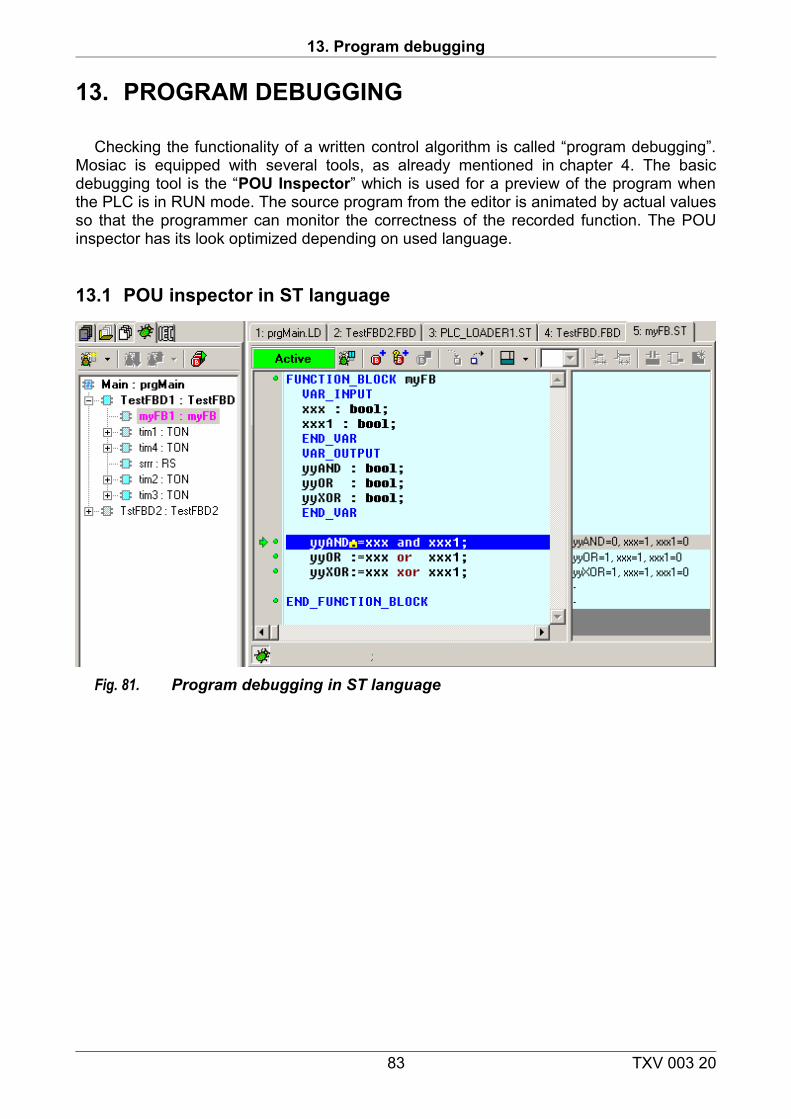
13. Program debugging
13. PROGRAM DEBUGGING
Checking the functionality of a written control algorithm is called “program debugging”. Mosiac is equipped with several tools, as already mentioned in chapter 4. The basic debugging tool is the “POU Inspector” which is used for a preview of the program when the PLC is in RUN mode. The source program from the editor is animated by actual values so that the programmer can monitor the correctness of the recorded function. The POU inspector has its look optimized depending on used language.
13.1 POU inspector in ST language
Fig. 81. Program debugging in ST language
83 TXV 003 20
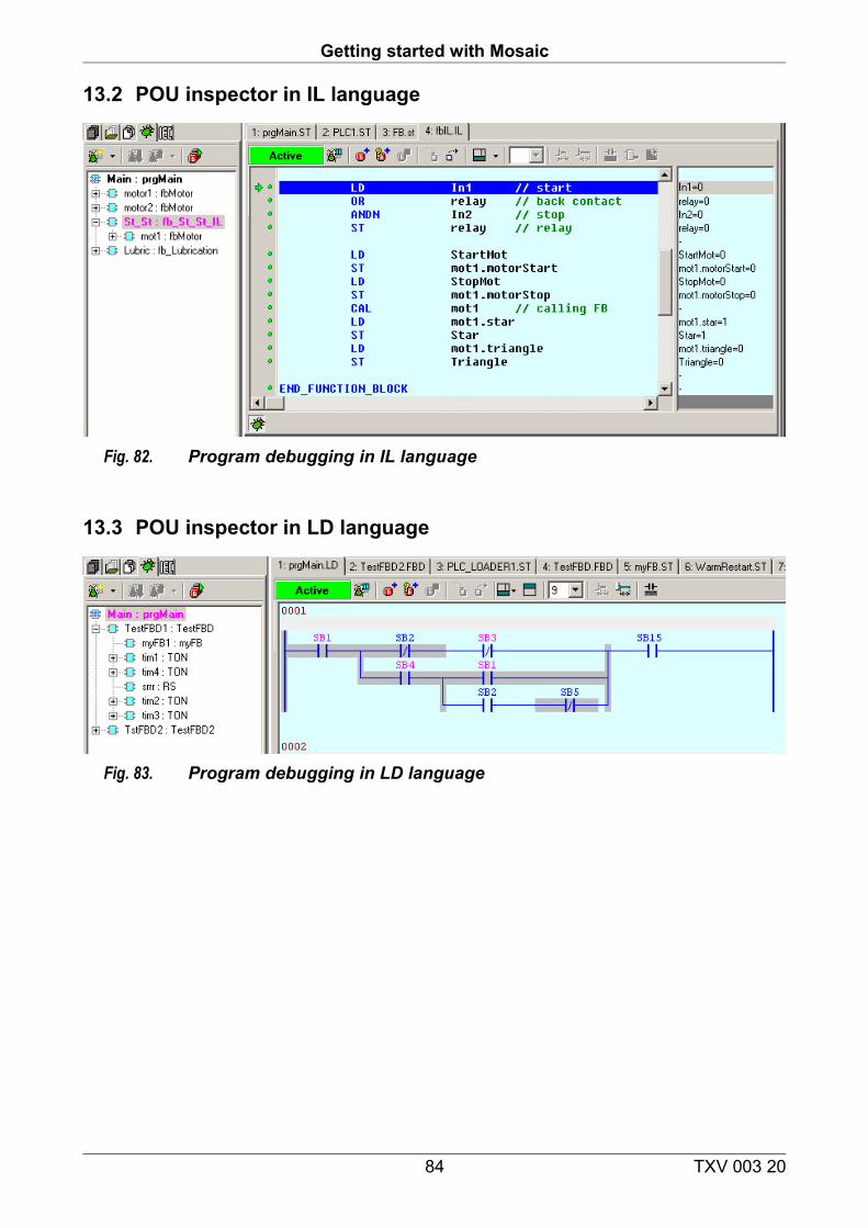
Getting started with Mosaic
13.2 POU inspector in IL language
Fig. 82. Program debugging in IL language
13.3 POU inspector in LD language
Fig. 83. Program debugging in LD language
84 TXV 003 20
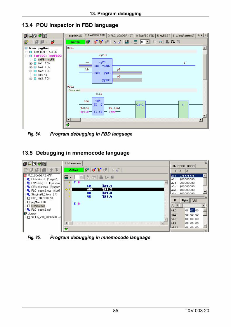
13. Program debugging
13.4 POU inspector in FBD language
Fig. 84. Program debugging in FBD language
13.5 Debugging in mnemocode language
Fig. 85. Program debugging in mnemocode language
85 TXV 003 20
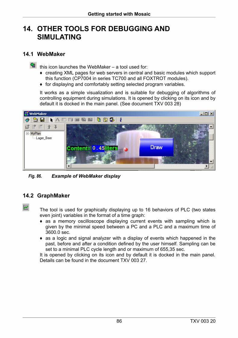
Getting started with Mosaic
14. OTHER TOOLS FOR DEBUGGING AND SIMULATING
14.1 WebMaker
this icon launches the WebMaker – a tool used for: ♦ creating XML pages for web servers in central and basic modules which support
this function (CP7004 in series TC700 and all FOXTROT modules). ♦ for displaying and comfortably setting selected program variables.
It works as a simple visualization and is suitable for debugging of algorithms of controlling equipment during simulations. It is opened by clicking on its icon and by default it is docked in the main panel. (See document TXV 003 28)
Fig. 86. Example of WebMaker display
14.2 GraphMaker
The tool is used for graphically displaying up to 16 behaviors of PLC (two states even joint) variables in the format of a time graph:♦ as a memory oscilloscope displaying current events with sampling which is
given by the minimal speed between a PC and a PLC and a maximum time of 3600.0 sec.
♦ as a logic and signal analyzer with a display of events which happened in the past, before and after a condition defined by the user himself. Sampling can be set to a minimal PLC cycle length and or maximum of 655,35 sec.
It is opened by clicking on its icon and by default it is docked in the main panel. Details can be found in the document TXV 003 27.
86 TXV 003 20
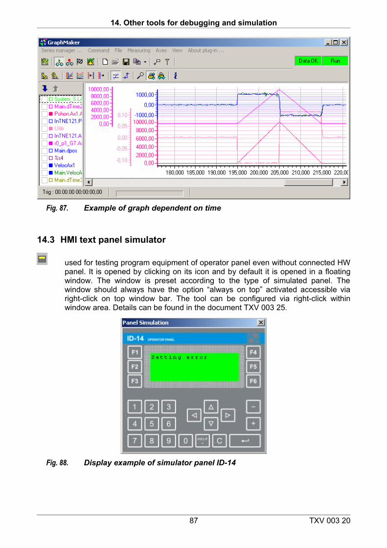
14. Other tools for debugging and simulation
Fig. 87. Example of graph dependent on time
14.3 HMI text panel simulator
used for testing program equipment of operator panel even without connected HW panel. It is opened by clicking on its icon and by default it is opened in a floating window. The window is preset according to the type of simulated panel. The window should always have the option “always on top” activated accessible via right-click on top window bar. The tool can be configured via right-click within window area. Details can be found in the document TXV 003 25.
Fig. 88. Display example of simulator panel ID-14
87 TXV 003 20
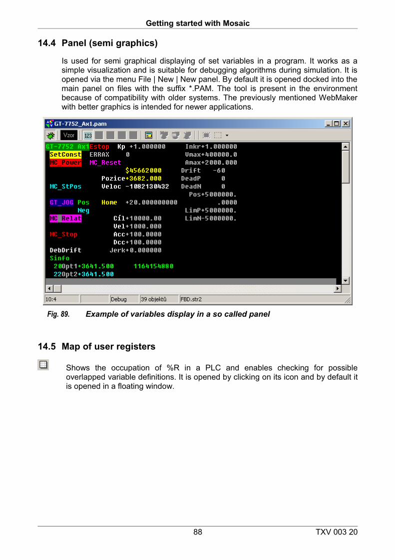
Getting started with Mosaic
14.4 Panel (semi graphics)
Is used for semi graphical displaying of set variables in a program. It works as a simple visualization and is suitable for debugging algorithms during simulation. It is opened via the menu File | New | New panel. By default it is opened docked into the main panel on files with the suffix *.PAM. The tool is present in the environment because of compatibility with older systems. The previously mentioned WebMaker with better graphics is intended for newer applications.
Fig. 89. Example of variables display in a so called panel
14.5 Map of user registers
Shows the occupation of %R in a PLC and enables checking for possible overlapped variable definitions. It is opened by clicking on its icon and by default it is opened in a floating window.
88 TXV 003 20
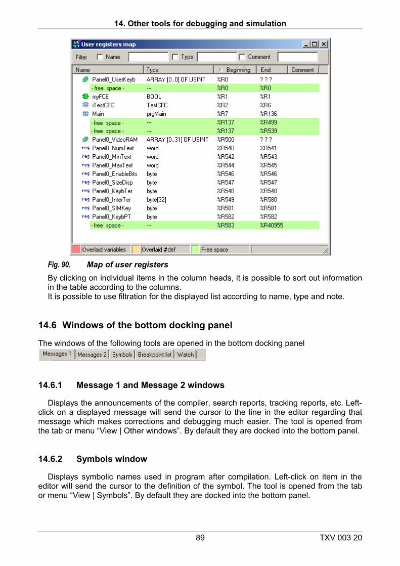
14. Other tools for debugging and simulation
Fig. 90. Map of user registersBy clicking on individual items in the column heads, it is possible to sort out information in the table according to the columns.It is possible to use filtration for the displayed list according to name, type and note.
14.6 Windows of the bottom docking panel
The windows of the following tools are opened in the bottom docking panel
14.6.1 Message 1 and Message 2 windows
Displays the announcements of the compiler, search reports, tracking reports, etc. Left-click on a displayed message will send the cursor to the line in the editor regarding that message which makes corrections and debugging much easier. The tool is opened from the tab or menu “View | Other windows”. By default they are docked into the bottom panel.
14.6.2 Symbols window
Displays symbolic names used in program after compilation. Left-click on item in the editor will send the cursor to the definition of the symbol. The tool is opened from the tab or menu “View | Symbols”. By default they are docked into the bottom panel.
89 TXV 003 20
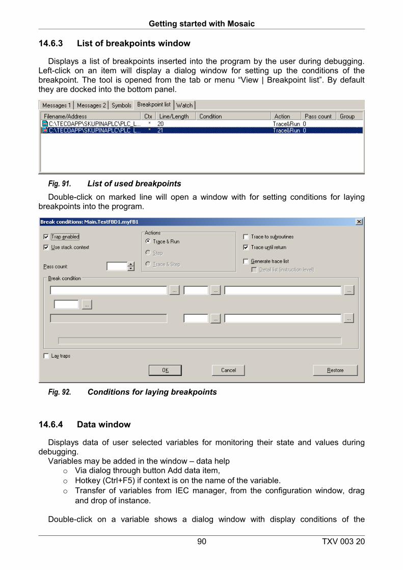
Getting started with Mosaic
14.6.3 List of breakpoints window
Displays a list of breakpoints inserted into the program by the user during debugging. Left-click on an item will display a dialog window for setting up the conditions of the breakpoint. The tool is opened from the tab or menu “View | Breakpoint list”. By default they are docked into the bottom panel.
Fig. 91. List of used breakpointsDouble-click on marked line will open a window with for setting conditions for laying
breakpoints into the program.
Fig. 92. Conditions for laying breakpoints
14.6.4 Data window
Displays data of user selected variables for monitoring their state and values during debugging.
Variables may be added in the window – data help o Via dialog through button Add data item, o Hotkey (Ctrl+F5) if context is on the name of the variable. o Transfer of variables from IEC manager, from the configuration window, drag
and drop of instance.
Double-click on a variable shows a dialog window with display conditions of the
90 TXV 003 20
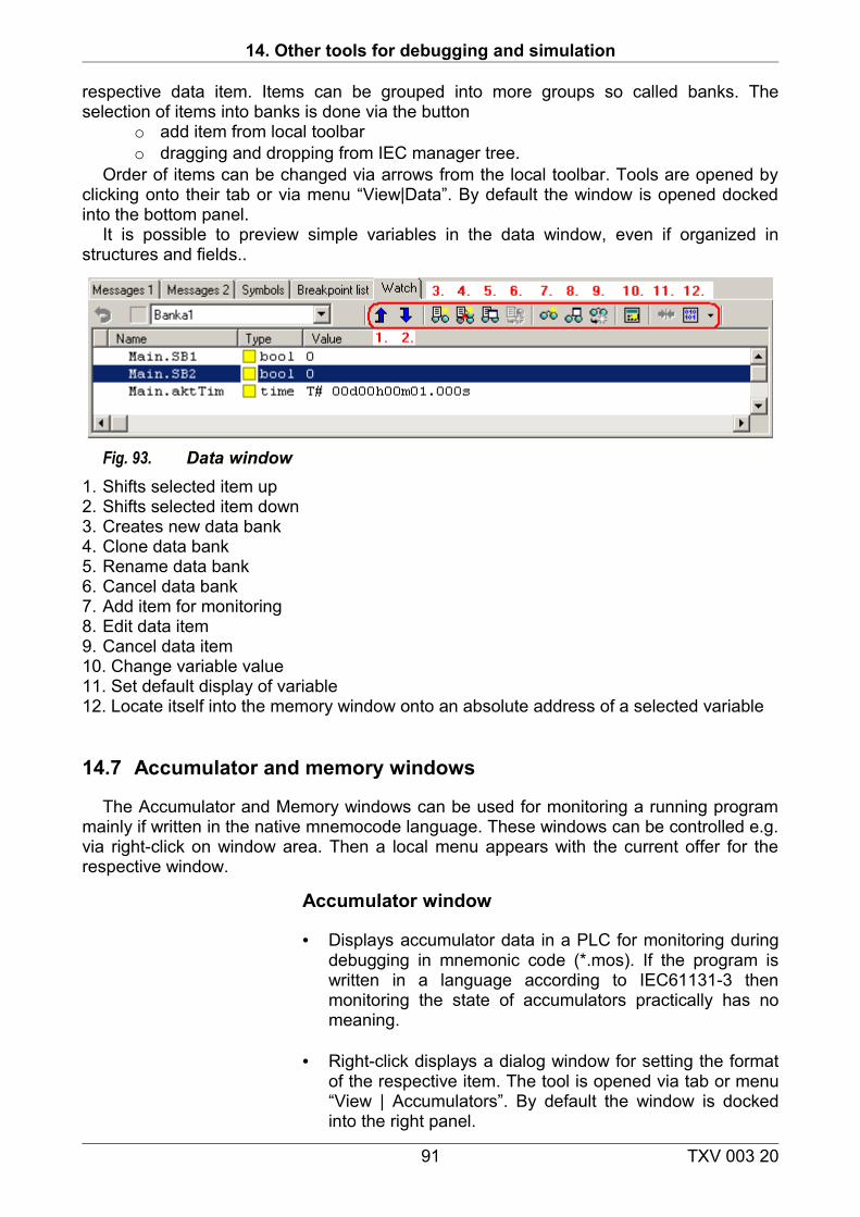
14. Other tools for debugging and simulation
respective data item. Items can be grouped into more groups so called banks. The selection of items into banks is done via the button
o add item from local toolbar o dragging and dropping from IEC manager tree.
Order of items can be changed via arrows from the local toolbar. Tools are opened by clicking onto their tab or via menu “View|Data”. By default the window is opened docked into the bottom panel.
It is possible to preview simple variables in the data window, even if organized in structures and fields..
Fig. 93. Data window1. Shifts selected item up2. Shifts selected item down3. Creates new data bank4. Clone data bank5. Rename data bank6. Cancel data bank7. Add item for monitoring8. Edit data item9. Cancel data item10. Change variable value11. Set default display of variable12. Locate itself into the memory window onto an absolute address of a selected variable
14.7 Accumulator and memory windows
The Accumulator and Memory windows can be used for monitoring a running program mainly if written in the native mnemocode language. These windows can be controlled e.g. via right-click on window area. Then a local menu appears with the current offer for the respective window.
Accumulator window
• Displays accumulator data in a PLC for monitoring during debugging in mnemonic code (*.mos). If the program is written in a language according to IEC61131-3 then monitoring the state of accumulators practically has no meaning.
• Right-click displays a dialog window for setting the format of the respective item. The tool is opened via tab or menu “View | Accumulators”. By default the window is docked into the right panel.
91 TXV 003 20
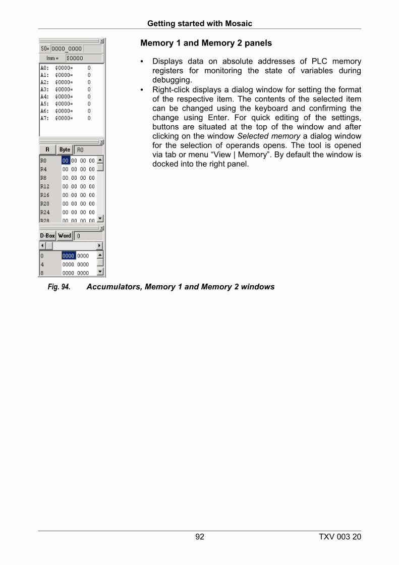
Getting started with Mosaic
Memory 1 and Memory 2 panels
• Displays data on absolute addresses of PLC memory registers for monitoring the state of variables during debugging.
• Right-click displays a dialog window for setting the format of the respective item. The contents of the selected item can be changed using the keyboard and confirming the change using Enter. For quick editing of the settings, buttons are situated at the top of the window and after clicking on the window Selected memory a dialog window for the selection of operands opens. The tool is opened via tab or menu “View | Memory”. By default the window is docked into the right panel.
Fig. 94. Accumulators, Memory 1 and Memory 2 windows
92 TXV 003 20
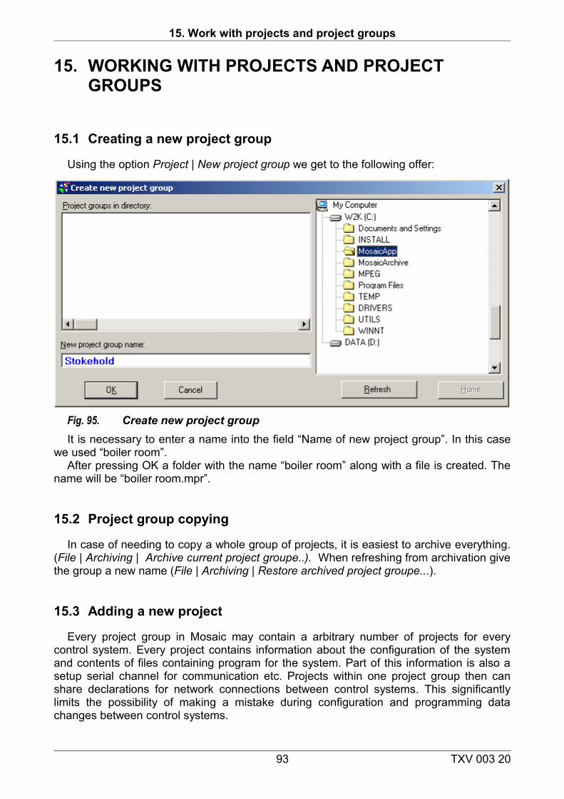
15. Work with projects and project groups
15. WORKING WITH PROJECTS AND PROJECT GROUPS
15.1 Creating a new project group
Using the option Project | New project group we get to the following offer:
Fig. 95. Create new project groupIt is necessary to enter a name into the field “Name of new project group”. In this case
we used “boiler room”.After pressing OK a folder with the name “boiler room” along with a file is created. The
name will be “boiler room.mpr”.
15.2 Project group copying
In case of needing to copy a whole group of projects, it is easiest to archive everything. (File | Archiving | Archive current project groupe..). When refreshing from archivation give the group a new name (File | Archiving | Restore archived project groupe...).
15.3 Adding a new project
Every project group in Mosaic may contain a arbitrary number of projects for every control system. Every project contains information about the configuration of the system and contents of files containing program for the system. Part of this information is also a setup serial channel for communication etc. Projects within one project group then can share declarations for network connections between control systems. This significantly limits the possibility of making a mistake during configuration and programming data changes between control systems.
93 TXV 003 20
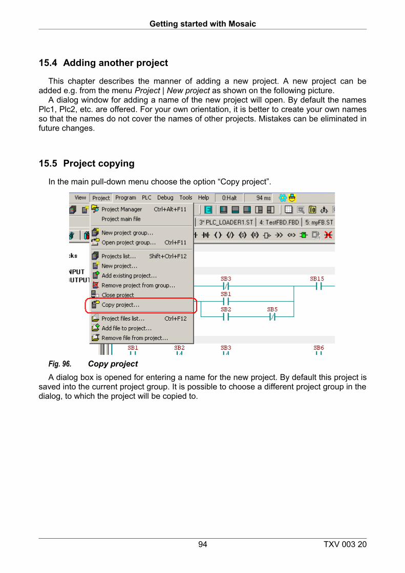
Getting started with Mosaic
15.4 Adding another project
This chapter describes the manner of adding a new project. A new project can be added e.g. from the menu Project | New project as shown on the following picture.
A dialog window for adding a name of the new project will open. By default the names Plc1, Plc2, etc. are offered. For your own orientation, it is better to create your own names so that the names do not cover the names of other projects. Mistakes can be eliminated in future changes.
15.5 Project copying
In the main pull-down menu choose the option “Copy project”.
Fig. 96. Copy projectA dialog box is opened for entering a name for the new project. By default this project is
saved into the current project group. It is possible to choose a different project group in the dialog, to which the project will be copied to.
94 TXV 003 20
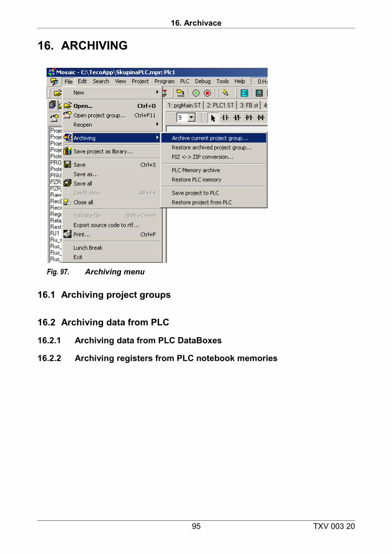
16. Archivace
16. ARCHIVING
Fig. 97. Archiving menu
16.1 Archiving project groups
16.2 Archiving data from PLC
16.2.1 Archiving data from PLC DataBoxes
16.2.2 Archiving registers from PLC notebook memories
95 TXV 003 20
Getting started with Mosaic
17. Documentation printing
Currently, only text parts of source codes from projects can be printed.
96 TXV 003 20
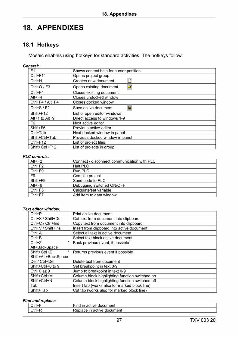
18. Appendixes
18. APPENDIXES
18.1 Hotkeys
Mosaic enables using hotkeys for standard activities. The hotkeys follow:
General:F1 Shows context help for cursor positionCtrl+F11 Opens project groupCtrl+N Creates new documentCtrl+O / F3 Opens existing documentCtrl+F4 Closes existing documentAlt+F4 Closes undocked windowCtrl+F4 / Alt+F4 Closes docked windowCtrl+S / F2 Save active documentShift+F12 List of open editor windowsAlt+1 to Alt+9 Direct access to windows 1-9F6 Next active editorShift+F6 Previous active editorCtrl+Tab Next docked window in panelShift+Ctrl+Tab Previous docked window in panelCtrl+F12 List of project filesShift+Ctrl+F12 List of projects in group
PLC controls:Alt+F2 Connect / disconnect communication with PLCCtrl+F2 Halt PLCCtrl+F9 Run PLCF9 Compile projectShift+F9 Send code to PLCAlt+F6 Debugging switched ON/OFFCtrl+F5 Calculate/set variableCtrl+F7 Add item to data window
Text editor window:Ctrl+P Print active documentCtrl+X / Shift+Del Cut text from document into clipboardCtrl+C / Ctrl+Ins Copy text from document into clipboardCtrl+V / Shift+Ins Insert from clipboard into active documentCtrl+A Select all text in active documentCtrl+B Select text block active documentCtrl+Z / Alt+BackSpace
Back previous event, if possible
Shift+Ctrl+Z / Shift+Alt+BackSpace
Returns previous event if possible
Del / Ctrl+Del Delete text from documentShift+Ctrl+0 to 9 Set breakpoint in text 0-9Ctrl+0 az 9 Jump to breakpoint in text 0-9Shift+Ctrl+M Column block highlighting function switched onShift+Ctrl+N Column block highlighting function switched offTab Insert tab (works also for marked block line)Shift+Tab Cut tab (works also for marked block line)
Find and replace:Ctrl+F Find in active documentCtrl+R Replace in active document
97 TXV 003 20
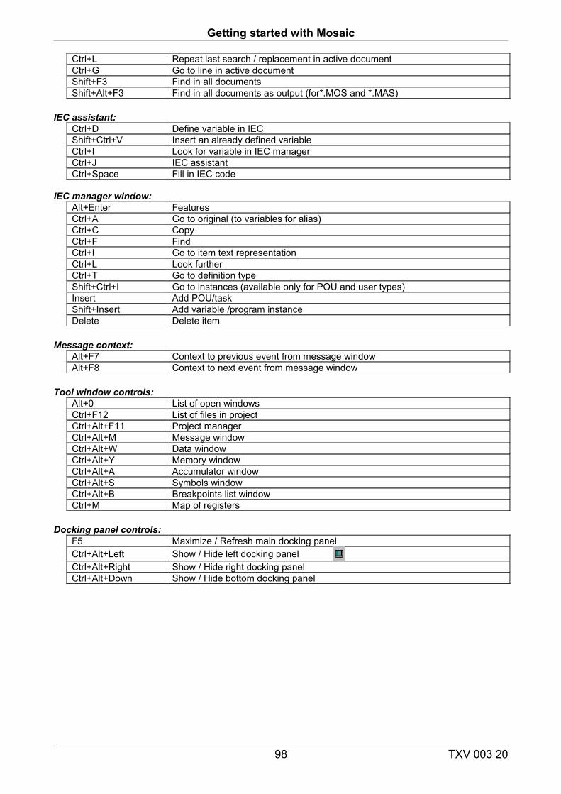
Getting started with Mosaic
Ctrl+L Repeat last search / replacement in active documentCtrl+G Go to line in active documentShift+F3 Find in all documentsShift+Alt+F3 Find in all documents as output (for*.MOS and *.MAS)
IEC assistant:Ctrl+D Define variable in IEC Shift+Ctrl+V Insert an already defined variableCtrl+I Look for variable in IEC managerCtrl+J IEC assistantCtrl+Space Fill in IEC code
IEC manager window:Alt+Enter FeaturesCtrl+A Go to original (to variables for alias)Ctrl+C CopyCtrl+F FindCtrl+I Go to item text representationCtrl+L Look furtherCtrl+T Go to definition typeShift+Ctrl+I Go to instances (available only for POU and user types)Insert Add POU/taskShift+Insert Add variable /program instanceDelete Delete item
Message context:Alt+F7 Context to previous event from message window Alt+F8 Context to next event from message window
Tool window controls:Alt+0 List of open windowsCtrl+F12 List of files in projectCtrl+Alt+F11 Project managerCtrl+Alt+M Message windowCtrl+Alt+W Data windowCtrl+Alt+Y Memory windowCtrl+Alt+A Accumulator windowCtrl+Alt+S Symbols windowCtrl+Alt+B Breakpoints list windowCtrl+M Map of registers
Docking panel controls:F5 Maximize / Refresh main docking panel Ctrl+Alt+Left Show / Hide left docking panel Ctrl+Alt+Right Show / Hide right docking panelCtrl+Alt+Down Show / Hide bottom docking panel
98 TXV 003 20