getting to know your - cad/cam solutions module. if you are new to cad/cam, the plug-and-play...
TRANSCRIPT

GETTING TO KNOW YOUR
Watch the included DVD, as many times as
you want!
Read and share this PlanScan Guide with
your team.
Go to www.e4d.com for more valuable
information.
Ask questions! Email our team at

GETTING TO KNOW YOUR PLANSCANFour helpful ways to be informed!
Watch the included DVD, as many times as you want!
Read and share this PlanScan Guide with your team.
Go to www.e4d.com for more valuable information.
Ask questions! Email our team at [email protected]
www.e4d.comCopyright 2014. All rights reserved.
Questions? Call E4D Customer Support 800.537.6070 or e-mail [email protected]
Welcome to the PlanScan CAD/CAM system and a new era in digital dentistry!
E4D’s recent partnership with Planmeca opens the door to unparalleled communication and coordination within the offi ce and among dental and laboratory professionals and specialists. Integrated digital 2D and 3D solutions for specialized treatment planning of implants, endo, and orthodontics are now possible with the powerful Romexis image management software.
PlanScan, PlanCAD, and PlanMill – all powered by E4D Technologies – comprise the Romexis CAD/CAM module.
If you are new to CAD/CAM, the plug-and-play convenience, portability, and fast video-rate data capture combined with easy design customization and micron-accurate milling, provide effi cient in-offi ce restorative capabilities without compromise.
If you are upgrading from a previous E4D or NEVO version, then the options for importing and superimposing soft tissue images with crown design and CBCT data as well as 3D tools for orthodontic and dental labs off er exciting new possibilities.
Regardless of your starting point, I am confi dent that the PlanScan CAD/CAM system will be an outstanding addition to your practice and bring a whole new level of satisfaction to you, your team, and your patients. Enjoy your E4D PlanScan experience!
Gary Severance, DDSChief Marketing Offi cerE4D Technologies

Table of Contents
Quick view tabs, pick the sections that best fi t you! ..............................................................................................................................................5PlanScan System ........................................................................................................................................................................... 6
New Hardware: ............................................................................................................................................................................. 7
Chemical Disinfection: ......................................................................................................................................................................................................7Removable Components .............................................................................................................................................................. 9
Connecting the Thunderbolt™ Adapter .....................................................................................................................................................................9Connecting the Scanning Tip .........................................................................................................................................................................................10Disconnecting the Scanning Tip ...................................................................................................................................................................................10Scanner Cradle (for Laptop Systems) ..........................................................................................................................................................................11
Windows 8.1 .................................................................................................................................................................................. 12
Romexis ......................................................................................................................................................................................... 13
Starting Romexis .................................................................................................................................................................................................................13Managing Patients in Planmeca Romexis ..................................................................................................................................................................13Searching Patients ..............................................................................................................................................................................................................14Sorting patients ...................................................................................................................................................................................................................14Selecting and opening patients ....................................................................................................................................................................................15 Starting a New Restoration ............................................................................................................................................................................................16
Button/Icon Changes .................................................................................................................................................................... 17
Patient Data Management ........................................................................................................................................................... 17
Importing CAD/CAM cases .............................................................................................................................................................................................17Importing 3D models ................................................................................................................................................................... 18
3D model import ................................................................................................................................................................................................................18Exporting 3D models ................................................................................................................................................................... 19
3D model export .................................................................................................................................................................................................................19Cloud export.........................................................................................................................................................................................................................19Send to iRomexis ................................................................................................................................................................................................................19DDX Export ...........................................................................................................................................................................................................................19Export CAD/CAM Case ......................................................................................................................................................................................................19
Retract ........................................................................................................................................................................................... 20
PlanCAD ........................................................................................................................................................................................ 21
Buccal/Opposing is the New Default ..........................................................................................................................................................................21Scan Type ...............................................................................................................................................................................................................................22
Scanning with PlanScan ............................................................................................................................................................... 22
Adjust Live View Window Size ..................................................................................................................................................... 26
Adjust the Scanning Field of View ............................................................................................................................................... 26
Evaluating the model ................................................................................................................................................................... 27
Highlight Low Data Areas is now Data Density View.............................................................................................................................................27New ICE View ........................................................................................................................................................................................................................27
Editing the Model ......................................................................................................................................................................... 28
Eraser Tool Replaces Trim Model ...................................................................................................................................................................................28Time Saver Tools ........................................................................................................................................................................... 29
Time Saver: Pre-op .............................................................................................................................................................................................................29Time Saver: Bite Registration ..........................................................................................................................................................................................31
Selecting the Bite Registration ................................................................................................................................................... 33
Model Alignment .......................................................................................................................................................................... 34
Orientation .................................................................................................................................................................................... 35
Bridges .......................................................................................................................................................................................... 35
Bridge Preparation .............................................................................................................................................................................................................35Updated Block Recommendation Chart ....................................................................................................................................................................36Bridge Setup Tab .................................................................................................................................................................................................................37Unlinking a Bridge ..............................................................................................................................................................................................................37Bridge Scanning ..................................................................................................................................................................................................................38Bridge Orientation..............................................................................................................................................................................................................38Drawing Pontic Margins ...................................................................................................................................................................................................39Designing the Bridge ........................................................................................................................................................................................................40Spacer Tool Settings on Bridges ....................................................................................................................................................................................41

WHAT YOU SHOULD KNOWQuick view tabs, pick the sections that best fi t you!
An in-depth look at the system hardware, the components, and Windows 8.1 basics.
New to Romexis? Learn about the changed icons in PlanScan and PlanCAD.
Video-like scanning and the bridge functionality. (These features were available in versions 4.6 and 5.0)
A group of essential documents that can make your life easier. Copy them, tear them off , or download new ones from www.e4d.com today!
Or pick them all! You’ll learn valuable information throughout the whole guide!
Parked Jobs option and details for milling Zirlux. (These features were available in versions 4.6 and 5.0)
Rotating Slice Plane ...........................................................................................................................................................................................................41Evaluating the Bridge ........................................................................................................................................................................................................42
Milling Center Changes ................................................................................................................................................................ 43
New Icon for a Parked Job ...............................................................................................................................................................................................43Zirlux FC2 Mill Maintenance ...........................................................................................................................................................................................44Zirlux FC2 Scale Factor ......................................................................................................................................................................................................44
Appendix ....................................................................................................................................................................................... 45
Scanning Buccal/Opposing ............................................................................................................................................................................................45New Documentation Available .................................................................................................................................................... 47

6 Getting to Know Your PlanScan 10822802.B
Pla
nSc
an &
Com
pon
ents PlanScan System
The PlanScan system includes a plug-and-play scanner and a laptop.
What’s New With PlanScan:
• Romexis software interface with optional access to full range of 2D and 3D imaging.
• Patient management in Romexis with search and sorting functions
• Additional import and export options for STL fi les
• Retract tool for virtual ditching of the 3D model (used in exporting STL cases)
Features Introduced with NEVO:
• Plug-and-play technology - You can now have multiple design stations and move the scanner from one station to another without shutting down the computer.
• The standoff and disposable sleeves have been replaced with solid removable tips. The system comes with three tips which means no down time between patients. Tips require eff ective high-level disinfection.
• The mirror in the tip is heated to prevent intraoral fogging.
• Convenient ON/OFF button on the wand to start and stop the scanning process.
• Scanning is faster and easier with video-like capture of data. You can watch your model build and move accordingly. Capture full arches and buccal bite cases faster and easier than before.
• New Time Saver functionality - You can copy your pre-op model to create your prep model or you can copy your prep model to create your bite registration model. After the model is copied, you can erase the pre-op or prep and just re-scan that area.
• Full ICE View - The scans are turned into clinically realistic images of the entire model
• New Erase Tool enables you to remove part of the scans. Did you spot a tissue tag or retraction cord covering the margin that needs to be removed? You can fi x the problem, erase that spot on the model, and re-scan that area. No need to start over.
• Improved automatic alignment of models
• Bridge capability (also available in version 4.6)

Customer Support 800.537.6070 7
Plan
Scan &
Compon
ents
New Hardware:
PlanScan requires a Windows 8.1 laptop and a scanner.
New Scanner
The new scanner has a removable tip. Press the green release button (below the scanning window) to separate the tip from the wand. Do NOT just pull on the tip.
Tips are consumable products (approximately 100 high level disinfections) and can be ordered in refi lls of 3. Tip can be removed and disinfected while the next tip is being used. See below for cleaning instructions on the tip and the system itself.
Icons in the lower-left corner of the screen indicate the status of the scanner.
Disconnected Connected - Cold Tip Disconnected
Heating - Stage 1 Heating - Stage 2 Ready
Cleaning the Scanner Tip
For intraoral scanning systems only.
The following instructions are for the removable tip of the scanner only and not for the entire scanner. See instructions below for cleaning the base of the scanner.
Chemical Disinfection:Note: These instructions were validated using MaxiCide Plus w/ Activator (3.4% Gluteraldehyde) disinfectant available from Henry Schein Dental (#102-2865).
DO NOT Autoclave. DO NOT place in Ultrasonic Cleaner.
1. Clean the tip for 2 minutes under running tap water at 22 - 25°C (4 liters/minute) to remove debris.
2. Test the potency of your activated MaxiCide Plus prior to disinfection. (Recommend MetriTest Strips by Metrex (HSD #602-3437)
3. Immerse the tip in activated MaxiCide Plus for 120 minutes (2 hours).
Note: Do not leave the tips soaking overnight.
8 Getting to Know Your PlanScan 10822802.B
Pla
nSc
an &
Com
pon
ents 4. Remove tip from the disinfectant.
5. Rinse disinfected part in three separate copious amounts of distilled water (1000 ml volume of water; minimum of 2” head height while part is immersed).
6. Agitate the tip in the water for 30 seconds and then let it stand in the water for another 30 seconds.
7. Repeat the agitation and soak in each of the other two containers with fresh distilled water.
Storage
1. Wipe water off mirror using non-woven optical wipes (recommend Kimwipes Lens Cleaning #101-7070).
2. Optional: Insert tip into a sterilization pouch. (recommend Self Seal Sterilization Pouch 5 ¼” x 10” [200/box] #112-4854)
3. Store for later use.
Note: Ensure the tip is dry before connecting it to the base.
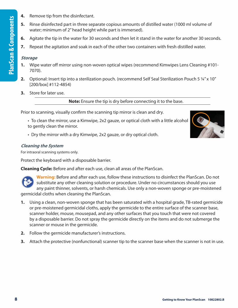
Prior to scanning, visually confi rm the scanning tip mirror is clean and dry.
• To clean the mirror, use a Kimwipe, 2x2 gauze, or optical cloth with a little alcohol to gently clean the mirror.
• Dry the mirror with a dry Kimwipe, 2x2 gauze, or dry optical cloth.
Cleaning the System
For intraoral scanning systems only.
Protect the keyboard with a disposable barrier.
Cleaning Cycle: Before and after each use, clean all areas of the PlanScan.
Warning: Before and after each use, follow these instructions to disinfect the PlanScan. Do not substitute any other cleaning solution or procedure. Under no circumstances should you use any paint thinner, solvents, or harsh chemicals. Use only a non-woven sponge or pre-moistened
germicidal cloths when cleaning the PlanScan.
1. Using a clean, non-woven sponge that has been saturated with a hospital grade, TB-rated germicide or pre-moistened germicidal cloths, apply the germicide to the entire surface of the scanner base, scanner holder, mouse, mousepad, and any other surfaces that you touch that were not covered by a disposable barrier. Do not spray the germicide directly on the items and do not submerge the scanner or mouse in the germicide.
2. Follow the germicide manufacturer’s instructions.
3. Attach the protective (nonfunctional) scanner tip to the scanner base when the scanner is not in use.

Customer Support 800.537.6070 9
Plan
Scan &
Compon
ents
Removable Components
The PlanScan system has a set of removable components.
Connecting the Thunderbolt™ Adapter
Properly connecting and disconnecting the scanner prevents damage to your devices.
1. Insert the Thunderbolt adapter into the adapter slot on the side of the laptop. (The adapter should remain attached, even when not in use.)
2. After opening the PlanCAD software, connect the red FireWire connector of the scanner into the white Thunderbolt™ adapter.
The laptop gives an audible signal to confi rm that the connection is fully seated.
To remove the scanner, hold the red end with one hand and with the other hand grasp the Thunderbolt adapter. Gently pull apart to disconnect. Leave the white Thunderbolt adapter attached to the computer.
Disconnecting the Thunderbolt™ Adapter
If you wish to remove the adapter from the laptop:
1. Disconnect the scanner and exit Romexis to the Windows desktop.
2. Navigate to the Eject Media icon in the lower left corner of the desktop.
3. Click the icon and choose Eject IEEE 1394 Controller.
4. Remove the Thunderbolt adapter from the laptop.
Note: Failure to follow this procedure may result in an inoperable scanner. For additional questions or concerns please contact Customer Support at 800.537.6700.
10 Getting to Know Your PlanScan 10822802.B
Pla
nSc
an &
Com
pon
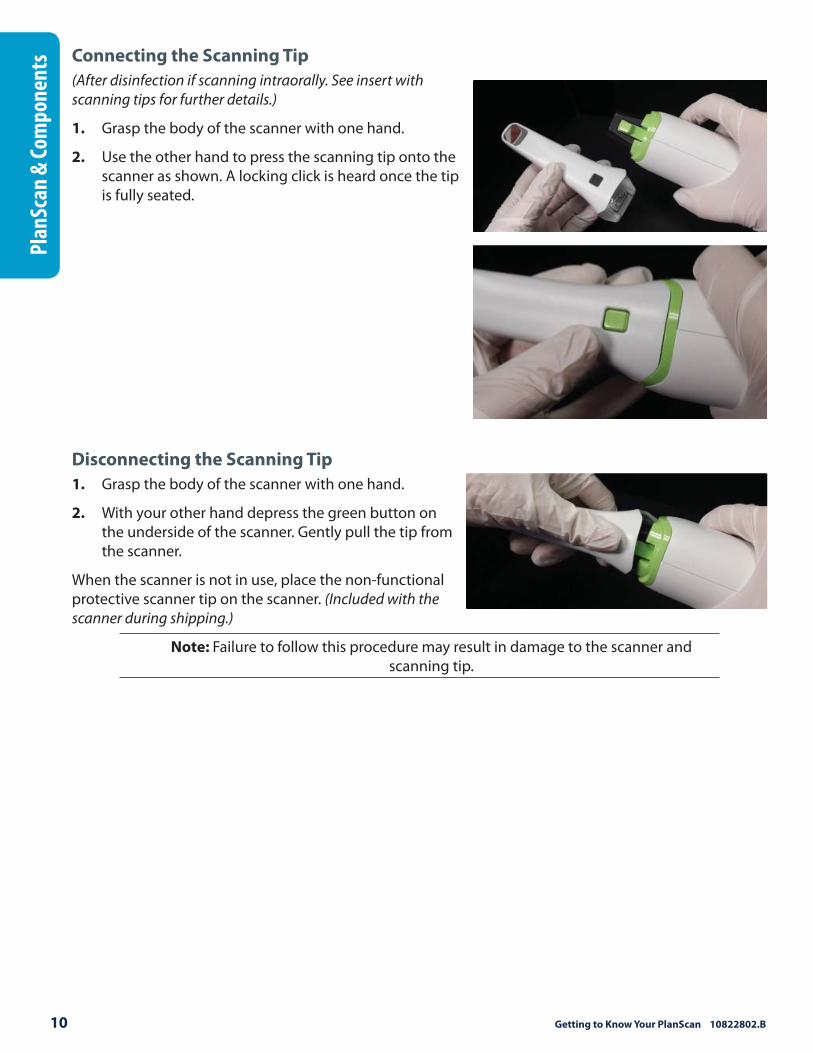
ents Connecting the Scanning Tip
(After disinfection if scanning intraorally. See insert with scanning tips for further details.)
1. Grasp the body of the scanner with one hand.
2. Use the other hand to press the scanning tip onto the scanner as shown. A locking click is heard once the tip is fully seated.
Disconnecting the Scanning Tip
1. Grasp the body of the scanner with one hand.
2. With your other hand depress the green button on the underside of the scanner. Gently pull the tip from the scanner.
When the scanner is not in use, place the non-functional protective scanner tip on the scanner. (Included with the scanner during shipping.)
Note: Failure to follow this procedure may result in damage to the scanner and scanning tip.
Customer Support 800.537.6070 11
Plan
Scan &
Compon
ents
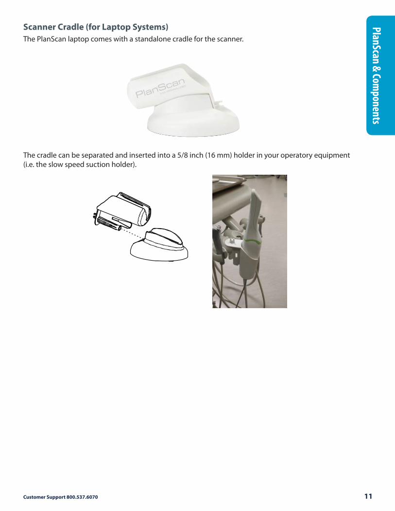
Scanner Cradle (for Laptop Systems)
The PlanScan laptop comes with a standalone cradle for the scanner.
The cradle can be separated and inserted into a 5/8 inch (16 mm) holder in your operatory equipment (i.e. the slow speed suction holder).

12 Getting to Know Your PlanScan 10822802.B
Pla
nSc
an &
Com
pon
ents Windows 8.1
The PlanScan system uses the Windows 8.1 operating system. This section is for those who may be unfamiliar with Windows 8.1.
Start Screen
When the laptop starts up, a Start screen appears with several tiles. Click the Romexis tile to open the Romexis software. The Desktop is also a tile on the Start screen. Your tiles may diff er from those shown.
If you click on another tile and don’t know how to exit, press the Windows key to return to the Start screen.
Screenshots
You may wish to save an image of the screen for communicating with associates or E4D Customer Support.
To take and save a screenshot:
1. On your keyboard, press the key and Prt Sc key.
2. The computer takes a screenshot and saves it in Libraries - Pictures - Screenshots.
3. The screenshots are automatically numbered. You can rename them if desired.
Shutting Down in Windows 8.1
The Start button is no longer on the desktop taskbar in Windows 8.1.
1. Move the mouse to the top-right corner or the bottom-right corner of the monitor to bring up the slide-out menu.
2. Click Settings.
3. Click Power.
4. Click Shut Down.
Note: Windows 8.1 should be updated regularly.
Desktop
Romexis

Customer Support 800.537.6070 13
Rom
exis & P
lanCA
DRomexis
Romexis is an all-in-one digital solution provided by Planmeca. It can store, capture, and manipulate 2D, and 3D images as well as allowing for treatment planning and exporting data.
Note: For more information, see the Romexis manual.
Starting Romexis
Click the Romexis icon on the Start Screen or double click the desktop icon. Refer to the Windows 8 section of this workbook for more information regarding this process.
OR double click the
desktop icon
Click to launch
Romexis
Managing Patients in Planmeca Romexis
Creating new patients
1. In the File menu click the Add Patient button.
The Files module opens.
2. Enter the necessary information and add a face photo if desired.
Note: The obligatory fi elds are Person ID, First name, and Last name.

14 Getting to Know Your PlanScan 10822802.B
Rom
exis
& P
lan
CAD
3. To save the patient into the database click the Save Patient button at the bottom of the screen.
Note: The changes are not saved unless Save Patient button is used.
Note: To view the newly created patient on the list, perform new patient search.
Searching Patients
Patients can be searched by ID or by name.
Search patients by ID
1. Select the option Find by Person ID from the drop-down menu.
2. Enter the patient ID in the text fi eld and click the Find button.
Search patients by name
1. Select Find by Name from the drop-down (see image above).
2. Enter the patient’s name in Last name, First name format into the search fi eld and touch the Enter key or click Find to make matching patients appear in the patient list.
To view all patients saved in the database use the * sign as the search term.
If a partial name is entered all patients whose last name begins with that partial string are shown. To search patients by their fi rst name replace the last name with the wild card *.
Examples:
• Doe, John: all patients whose last name is Doe and fi rst name John
• S: all patients whose last name starts with the letter S
• Smi : all patients whose last name starts with ‘Smi’, e.g. Smith and Smiley
• Van Gogh: all patients with the last name Van Gogh
• *, Paul: all patients whose fi rst name is Paul
Sorting patients
Patients in the patient list can be sorted by ID, last name, fi rst name, birth date, age, gender, phone number, the number of assigned providers and type (for virtual and template patients) as well as by assignments.
To sort patients click the respective column title.

Customer Support 800.537.6070 15
Rom
exis & P
lanCA
DSelecting and opening patients
1. Click the patient name in the patient list.
2. Click the Select button (or double-click the patient name).
3. In the opening dialogue select the reason for accessing the patient record and click OK.
Note: This request can be set as optional in the Planmeca Romexis Confi guration application. See the Romexis manual for more details.
Planmeca Romexis automatically opens the Files module.

16 Getting to Know Your PlanScan 10822802.B
Rom
exis
& P
lan
CAD
The reason for accessing a patient record is saved and displayed in the dental record under the patient case history.
The name of the active patient is always visible in the upper right corner of the screen. Several patient records can be open at a time but only one of the open records is active at a time.
To close the active patient click the Close Patient button.
To view all open patients click the arrow of the drop-down menu.
To select and modify another open patient select the name from the drop-down menu.
Starting a New Restoration
1. Open the desired patient fi le.
2. Click CAD/CAM.
3. To start a new scan click New Scan and Design.
Note: Click New Scan Only if you do not have a design license.
4. To open an existing scan or restoration (crown, inlay, onlay etc.) double-click a case on the list or click the Open Restoration button.
Note: Click Open for Design Only if you do not have a scanning license.
The case opens in the Planmeca PlanScan Full System Setup tab.
From here, the majority of the screens are similar to what you are used to in previous DentaLogic versions. Click Home at the top of the screen to exit the PlanScan and PlanCAD software and return to the Romexis screens.

Customer Support 800.537.6070 17
Rom
exis & P
lanCA
DButton/Icon Changes
The functionality has remained the same, but there are some new icons in the PlanScan and PlanCAD software.
Icon Previous Version PlanScan/PlanCAD
Data Density View
View ICE
Impression Mode
Return HomeExit CAD/CAM
Patient Data Management
The open architecture of Romexis gives you the freedom to Import scan data from our previous versions of software into PlanCAD. It also allows the export of data to DDX, Planmeca Romexis Cloud, and to your local machine.
Importing CAD/CAM cases
You can import cases from another Planmeca or E4D system into Romexis. Cases from previous versions can be opened in PlanScan, but the Scan tab is disabled. Older models cannot be trimmed or aligned.
1. In Romexis, click File - Import - Import CAD/CAM Case.
2. A new screen appears. Click Browse to fi nd the fi le with the time and date stamp as the folder name, ex. [3-25-2014 10:37:42 AM].
• If you have exported the fi les from another Planmeca system, a .zip fi le is created with the restoration number(s) as the name. Extract the fi les and open the folder to fi nd the time and date stamped folder.
• E4D patient fi les are stored under the customer name or whatever naming convention was used in the E4D system. c:\d4d\DesignCenter\patients\Joe Smith\restorations\

18 Getting to Know Your PlanScan 10822802.B
Rom
exis
& P
lan
CAD
3. Select how you want to import it:
• Import to current patient
• Create new patient (available when there is not a patient fi le currently open)
• Select an existing patient (available when there is not a patient fi le currently open)
Importing 3D models
3D model import
To import models click 3D model import.
The following window opens.
You may import models either from an external source or from Planmeca Romexis 3D module’s Volumes tab.
To import models from an external source:
1. Click Browse.
2. Browse to the folder from which you want to import the models.
3. Select the fi les and click Open.
The imported fi les appear in the Patient’s case fi les window.

Customer Support 800.537.6070 19
Rom
exis & P
lanCA
DTo import models from the Planmeca Romexis 3D module’s Volumes list:
1. Click Select.
2. In the following window select the fi le to import and click OK.
3. Select the model(s) to import and click OK.
The imported fi les appear in the Volumes tab.
Exporting 3D models
3D model export
To export 3D models in STL format click 3D model export.
Note: For equigingival or subgingival margins, ensure you have used the Retract margin tool to defi ne your margin. The drawn margin is not converted to STL and the recipient will not be able to use ICE View to fi nd the margin. See the “Retract” section
below for more information.
Cloud export
To export scans and restorations via Planmeca Romexis Cloud click Cloud export. For more information on how to use the Cloud service, see the User Manual.
Send to iRomexis
To send the model to iOS click Send to iRomexis. For more information on how to use the Planmeca iRomexis see Planmeca Romexis User’s Manual APPENDIX C: “PLANMECA iROMEXIS”.
DDX Export
To send STL models via the DDX website, click DDX Export. For more information on how to use the DDX Export, see the User Manual
Export CAD/CAM Case
To export a fi le to share with another Planmeca system, click File - Export - Export CAD/CAM Case.
Select the destination folder and enter a fi le name

20 Getting to Know Your PlanScan 10822802.B
Rom
exis
& P
lan
CAD
Retract
Use the Retract tool on STL export cases with a subgingival or equigingival margin. This tool ditches the 3D model since the margin line does not convert to STL.
Note: ICE View is not converted to STL format and cannot be used as a visual aid by the recipient of your case.
Without virtual ditching, the margin may be diffi cult for your recipient to see.
1. After the margin has been drawn and edited, click Retract.
The system virtually removes part of the model outside of the drawn margin.
Margin drawn
No ditching
Margin drawn
With ditching
Note: Any changes to the margin will require the ditching to be redone. If you are doing a multiple restoration case, fi nish all of the margin edits before using the
Retract tool.
2. Click Toggle Margin to view the ditched area without the margin. This is similar to what your STL recipient will see.
3. Click Toggle Retraction to show/hide the virtual ditching.

Customer Support 800.537.6070 21
Scann
ing &
Bridges
PlanCAD
PlanCAD includes the scanning capabilities that and the bridge software that were introduced with the NEVO (5.0) version. For complete instructions, see the User Manual.
Buccal/Opposing is the New Default
With the faster scanning, more clinical operators prefer the Buccal/Opposing option for capturing the occlusion data.
Many clinical operators scan the Opposing while the patient is being anesthetized. Scan the Buccal Bite after the tooth has been prepped.
If you are unfamiliar with scanning the Buccal Bite and Opposing, see the back of this booklet.
Scan Tab Layout
The Scan tab has a diff erent look and a lot of new functionality.
1
2
3
4
1. Scan Type
2. Model Editing Tools
3. Evaluation Tools
4. Alignment Tools
22 Getting to Know Your PlanScan 10822802.B
Scan
nin
g &
Bri
dges
Scan Type
The default selection is always Pre-op (formerly Clone). The other available options depend on whether Bite Registration or Buccal/Opposing was selected on the Setup tab.
Click the desired icon to select it.
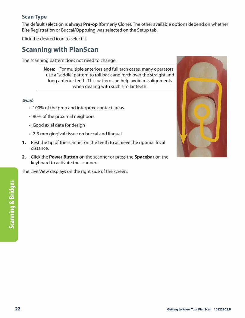
Scanning with PlanScan
The scanning pattern does not need to change.
Note: For multiple anteriors and full arch cases, many operators use a “saddle” pattern to roll back and forth over the straight and
long anterior teeth. This pattern can help avoid misalignments when dealing with such similar teeth.
Goal:
• 100% of the prep and interprox. contact areas
• 90% of the proximal neighbors
• Good axial data for design
• 2-3 mm gingival tissue on buccal and lingual
1. Rest the tip of the scanner on the teeth to achieve the optimal focal distance.
2. Click the Power Button on the scanner or press the Spacebar on the keyboard to activate the scanner.
The Live View displays on the right side of the screen.

Customer Support 800.537.6070 23
Scann
ing &
Bridges
3. Start scanning with an occlusal view of the preparation or proximals. The fi rst scan still determines the orientation of the model.
The system starts scanning as you get into place and stop moving. Once the fi rst scan is taken and the model starts to build, move slowly in the scan pattern. You do not have to stop to take individual pictures. The scanner picks up the data as you move. You can watch as the model builds on the left to see what data has been captured and what is still needed.
4. Watch the model building on the left as you scan. The Focal Distance Gradient (see following section for more information) shows you the most recently applied information and helps you visualize where you need to go.
In previous software versions, the operator’s attention was usually on the Live View to watch the shrinking target indicator and to move the scanner in half-tooth increments for the next scan. Most operators kept the building model on the left in their periphery vision to see where the scans were added. With PlanScan, most operators watch the building model and use the Live View only when they need to alter their positioning. With the new video-like rate of capture, the scanner is almost always moving and the building model shows the operator what they have and what is still needed. Watch the focal gradient to see where you are and the blue raw data model shows what is still needed.
24 Getting to Know Your PlanScan 10822802.B
Scan
nin
g &
Bri
dges
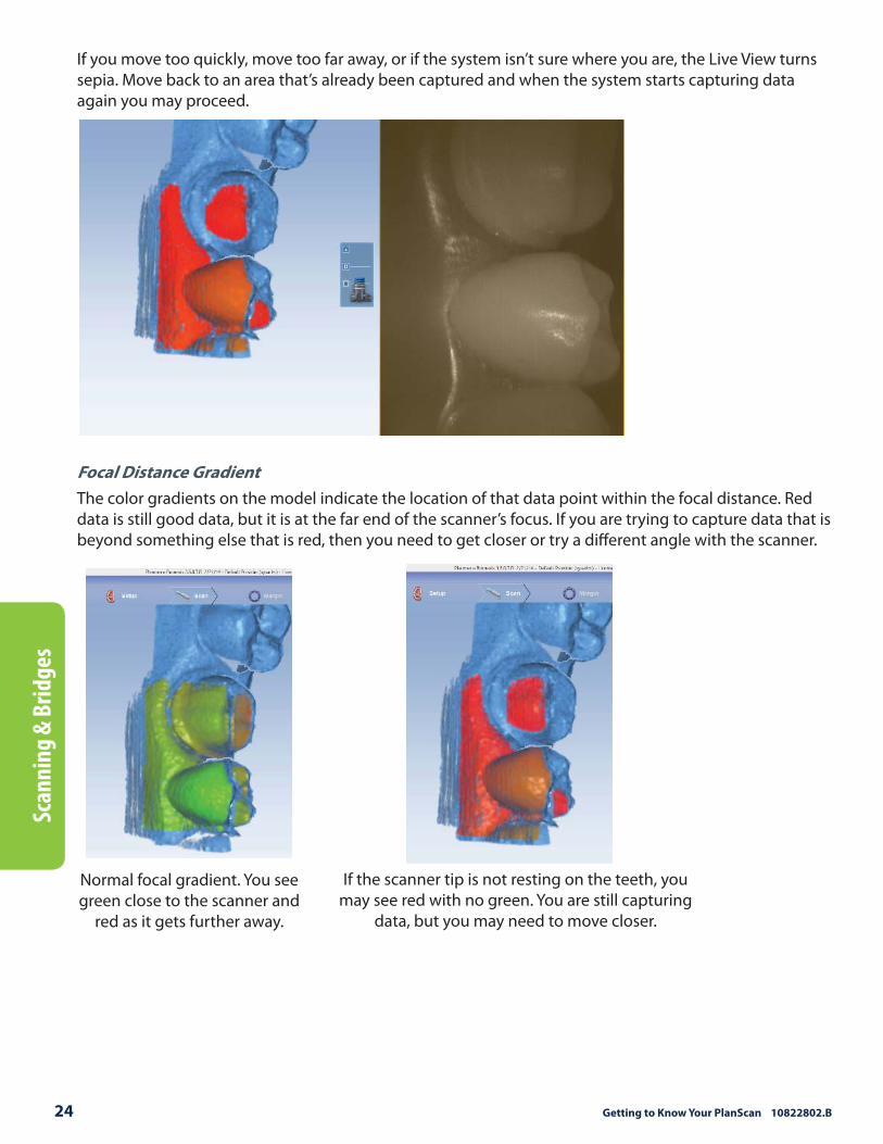
If you move too quickly, move too far away, or if the system isn’t sure where you are, the Live View turns sepia. Move back to an area that’s already been captured and when the system starts capturing data again you may proceed.
Focal Distance Gradient
The color gradients on the model indicate the location of that data point within the focal distance. Red data is still good data, but it is at the far end of the scanner’s focus. If you are trying to capture data that is beyond something else that is red, then you need to get closer or try a diff erent angle with the scanner.
Normal focal gradient. You see green close to the scanner and
red as it gets further away.
If the scanner tip is not resting on the teeth, you may see red with no green. You are still capturing
data, but you may need to move closer.
Customer Support 800.537.6070 25
Scann
ing &
Bridges
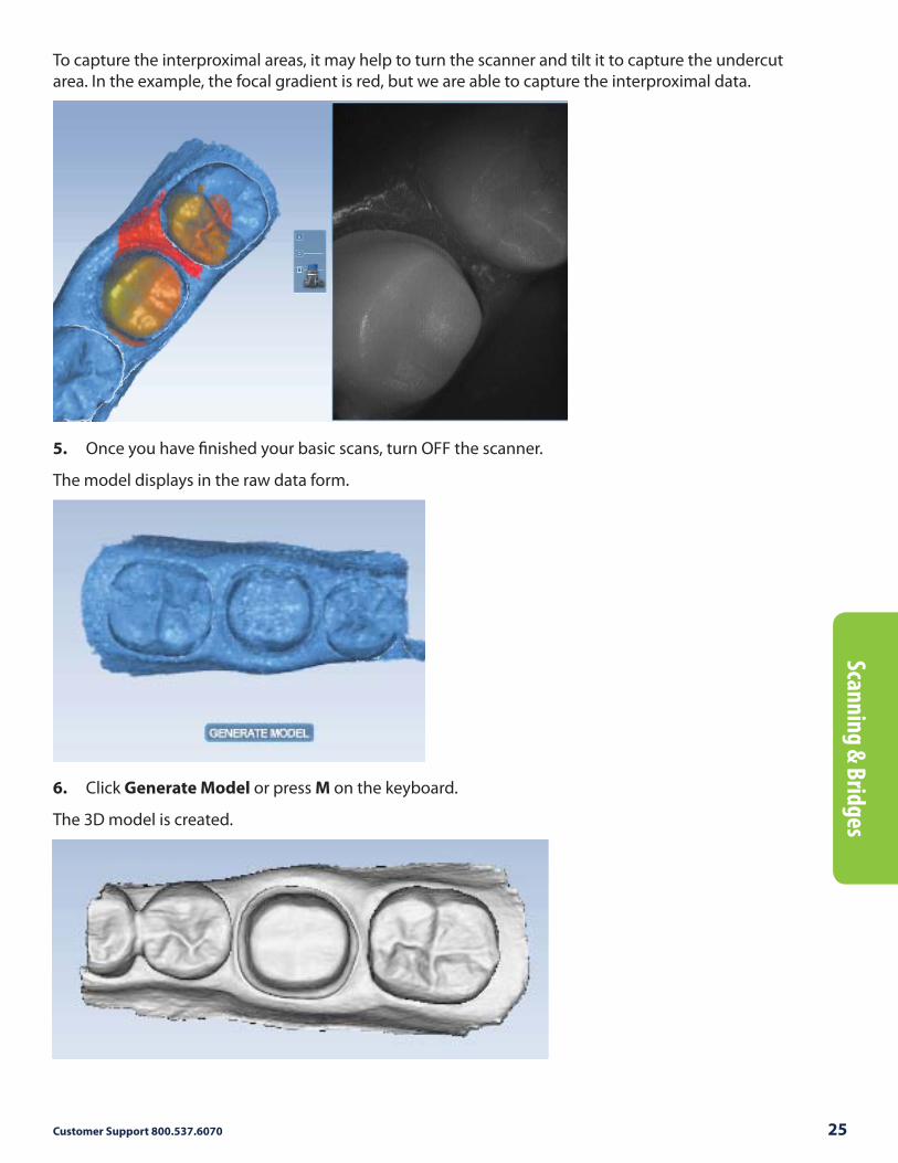
To capture the interproximal areas, it may help to turn the scanner and tilt it to capture the undercut area. In the example, the focal gradient is red, but we are able to capture the interproximal data.
5. Once you have fi nished your basic scans, turn OFF the scanner.
The model displays in the raw data form.
6. Click Generate Model or press M on the keyboard.
The 3D model is created.

26 Getting to Know Your PlanScan 10822802.B
Scan
nin
g &
Bri
dges
Adjust Live View Window Size
While the Live View is active, The window size can be adjusted. By default, the Live View is large enough to fi ll the height of the scanning window. To make it smaller, place the mouse cursor on the left edge of the Live View. Right-click and drag the window to the desired size.
The Live View returns to the default size the next time it is activated.
Adjust the Scanning Field of View
The Field of View or scanning area can be reduced if the movement of tongue, cheek, instruments, etc., is interfering with your scans.
Click and drag the Field of View indicator to the desired setting. In the examples, the change in the Live View has been outlined in yellow for emphasis.

Customer Support 800.537.6070 27
Scann
ing &
Bridges
Evaluating the model
Highlight Low Data Areas is now Data Density View
The button has been renamed, but the functionality is the same. Click Data Density View to evaluate the model and fi nd any areas that need to be rescanned.
New ICE View
The ICE View now covers the entire model. This view is mainly utilized on the Margin tab, but is also available on the Scan tab. The example below shows an intraoral scan of an implant with a metal crown at the edge of the scans. No treatment of the metals was needed before scanning.
To the left of the ICE View button is the ICE Contrast slider. Click and drag within the square (up and down, left and right) to change the brightness and contrast of the ICE View if needed to see part of the model better. This is currently only available on the Scan tab. To reset the ICE Contrast to the default, activate and deactivate the Erase button to regenerate the model.

28 Getting to Know Your PlanScan 10822802.B
Scan
nin
g &
Bri
dges
Editing the Model
Eraser Tool Replaces Trim Model
Trim Model has been replaced with the Eraser Brush.
With the new Eraser, click and drag to remove extra data (i.e. tongue, cheeks, etc.).
In previous versions, if you told the system to trim a part of the model, then subsequent scans of the same area would be ignored. With this new tool, you can erase an area that needs to be rescanned. If you spot a problem (i.e. the margin is partially hidden by cord or tissue), you can erase that area, correct the problem on your model or intraorally, then rescan just that area! You do not have to start over. Be sure to erase and rescan ALL areas that were changed.
The Eraser is also used in the new Time Saver tools (see following sections).
Click the Eraser tool to deactivate it and regenerate the model.
Note: You can zoom in and out to make the model larger or smaller in relation to the Eraser tool. You can also select a diff erent circle size above the Eraser icon.

Customer Support 800.537.6070 29
Scann
ing &
Bridges
Time Saver Tools
These Time Saver Tools are recommended for single unit cases. For multiple unit cases and bridges, you would usually delete more of the model than you would keep. Large gaps in the model are not optimal. If 50% or more of the model would be removed, it is suggested that you rescan instead of using the Time Saver feature.
Time Saver: Pre-op
1. Scan the Pre-op with the normal scan pattern. Remember that you can do this while the patient is being anesthetized.
Note: Time Saver is not recommended for impression scans.
2. Use all of the evaluation and editing tools mentioned above.
Note: ICE and Data Density are available for all scan types.
3. Prepare the tooth.
4. On the Scan tab, click Scan Prep.
A Time Saver message appears. This message appears when the pre-op is scanned fi rst. The Time Saver option allows you to duplicate the pre-op model and use the same data for the preparation model.
5. Click OK to use the Time Saver. If you do not wish to use the Time Saver option, the preparation and proximals can be scanned on their own. The following instructions assume the use of the Time Saver option.
A copy of the pre-op model is created in the preparation model color.
p.p.p

30 Getting to Know Your PlanScan 10822802.B
Scan
nin
g &
Bri
dges
6. Click the Eraser Tool.
7. Erase the tooth that has been prepared and the marginal ridges of the proximal teeth.
Note: If you erase the buccal and lingual gingival data, most of your model disappears. If this happens, the other side of your model reappears as you scan the connection.
8. Click the Eraser Tool to deactivate it. The model is smooth where the data has been erased.
9. Activate the wand and scan begin the scans with the occlusal of one of the proximal teeth. Once you have established your position, you can begin scanning the preparation. DO NOT start your scans over the missing data.
10. Scan the entire preparation and any of the proximal tooth data that was removed.
11. Click Generate Model or press M on the keyboard.

Customer Support 800.537.6070 31
Scann
ing &
Bridges
The Align Pre-op icon displays a green light if the models are aligned. A red light means that alignment must be done manually.
12. Click the Align Pre-op button to verify the alignment. See below for how to manually align the models if needed. Click the button again to deactivate it and return to the main scan screen.
Time Saver: Bite Registration
1. On the Setup tab, select Bite Registration.
2. On the Scan tab, click Scan Prep and scan the preparation model fi rst.
3. Click Scan Bite.
A Time Saver message appears. This message appears when the preparation is scanned fi rst. The Time Saver option allows you to duplicate the preparation model and use the same data for the bite registration model.
4. Click OK to use the Time Saver. If you do not wish to use the Time Saver option, the bite registration and proximals can be scanned on their own. The following instructions assume the use of the Time Saver option.
A copy of the preparation model is created in the bite registration model color.

32 Getting to Know Your PlanScan 10822802.B
Scan
nin
g &
Bri
dges
5. Click the Eraser Tool.
6. Erase the preparation and the marginal ridges of the proximal teeth.
Note: If you erase the buccal and lingual gingival data, most of your model disappears. If this happens, the other side of your model will reappear as you scan the connection.
7. Click the Eraser Tool to deactivate it. The model is smooth where the data has been erased.
8. Activate the wand and begin the scans with the occlusal of one of the proximal teeth. Once you have established where you are, you can begin scanning the bite registration data.
Customer Support 800.537.6070 33
Scann
ing &
Bridges
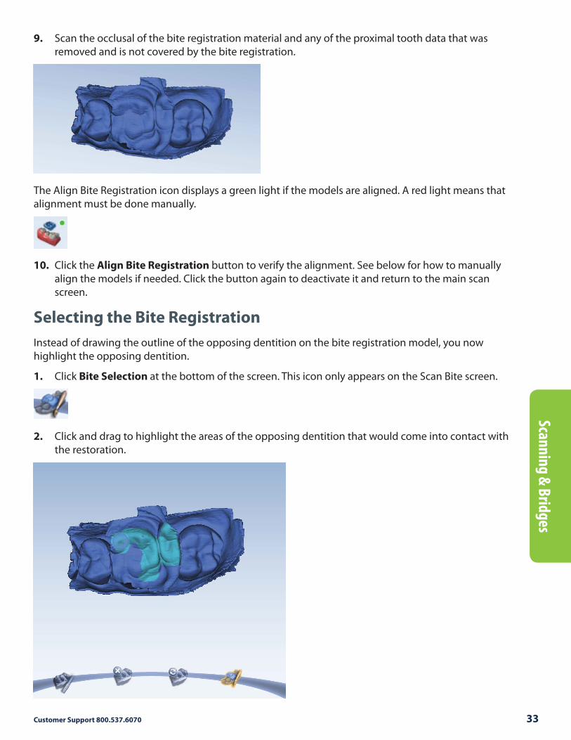
9. Scan the occlusal of the bite registration material and any of the proximal tooth data that was removed and is not covered by the bite registration.
The Align Bite Registration icon displays a green light if the models are aligned. A red light means that alignment must be done manually.
10. Click the Align Bite Registration button to verify the alignment. See below for how to manually align the models if needed. Click the button again to deactivate it and return to the main scan screen.
Selecting the Bite Registration
Instead of drawing the outline of the opposing dentition on the bite registration model, you now highlight the opposing dentition.
1. Click Bite Selection at the bottom of the screen. This icon only appears on the Scan Bite screen.
2. Click and drag to highlight the areas of the opposing dentition that would come into contact with the restoration.
34 Getting to Know Your PlanScan 10822802.B
Scan
nin
g &
Bri
dges
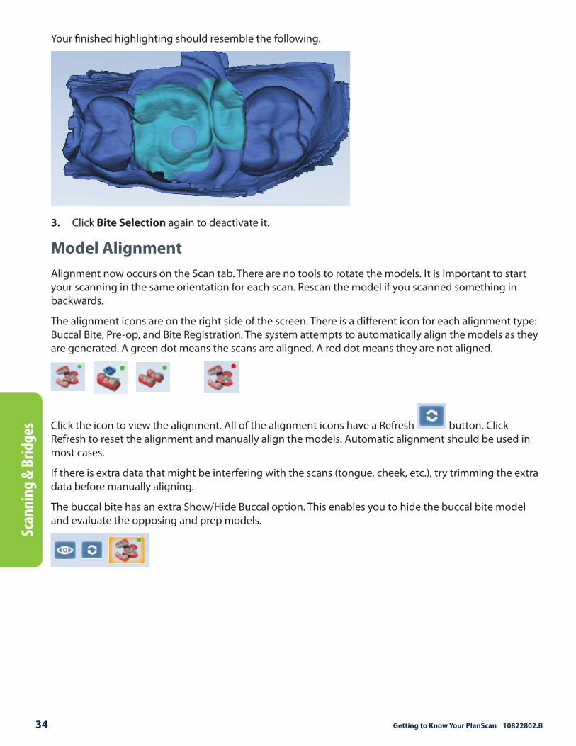
Your fi nished highlighting should resemble the following.
3. Click Bite Selection again to deactivate it.
Model Alignment
Alignment now occurs on the Scan tab. There are no tools to rotate the models. It is important to start your scanning in the same orientation for each scan. Rescan the model if you scanned something in backwards.
The alignment icons are on the right side of the screen. There is a diff erent icon for each alignment type: Buccal Bite, Pre-op, and Bite Registration. The system attempts to automatically align the models as they are generated. A green dot means the scans are aligned. A red dot means they are not aligned.
Click the icon to view the alignment. All of the alignment icons have a Refresh button. Click Refresh to reset the alignment and manually align the models. Automatic alignment should be used in most cases.
If there is extra data that might be interfering with the scans (tongue, cheek, etc.), try trimming the extra data before manually aligning.
The buccal bite has an extra Show/Hide Buccal option. This enables you to hide the buccal bite model and evaluate the opposing and prep models.

Customer Support 800.537.6070 35
Scann
ing &
Bridges
To align models, drag and drop the buccal bite, pre-op, or bite registration over the prep model.
The models snap into place.
To access the menu options at the top or to return to scanning, deactivate the selected Alignment icon. You cannot proceed if the Alignment icon is active (orange).
Orientation
The pink shading for undercuts has been removed from Orientation.
Bridges
Bridge cases are unique in that they are designed as individual teeth and milled as one unit.
This document assumes familiarity with multiple restoration cases and other intermediate to advanced topics. Refer to your User Manual for more information.
Bridge Preparation
Ensure the preparations for the abutment teeth are not angled in diff erent directions. If one is pointed towards the lingual and one towards the buccal, there may be issues with path of insertion and overmilling. Cantilever and Maryland bridges are not recommended by the material
manufacturers.
36 Getting to Know Your PlanScan 10822802.B
Scan
nin
g &
Bri
dges
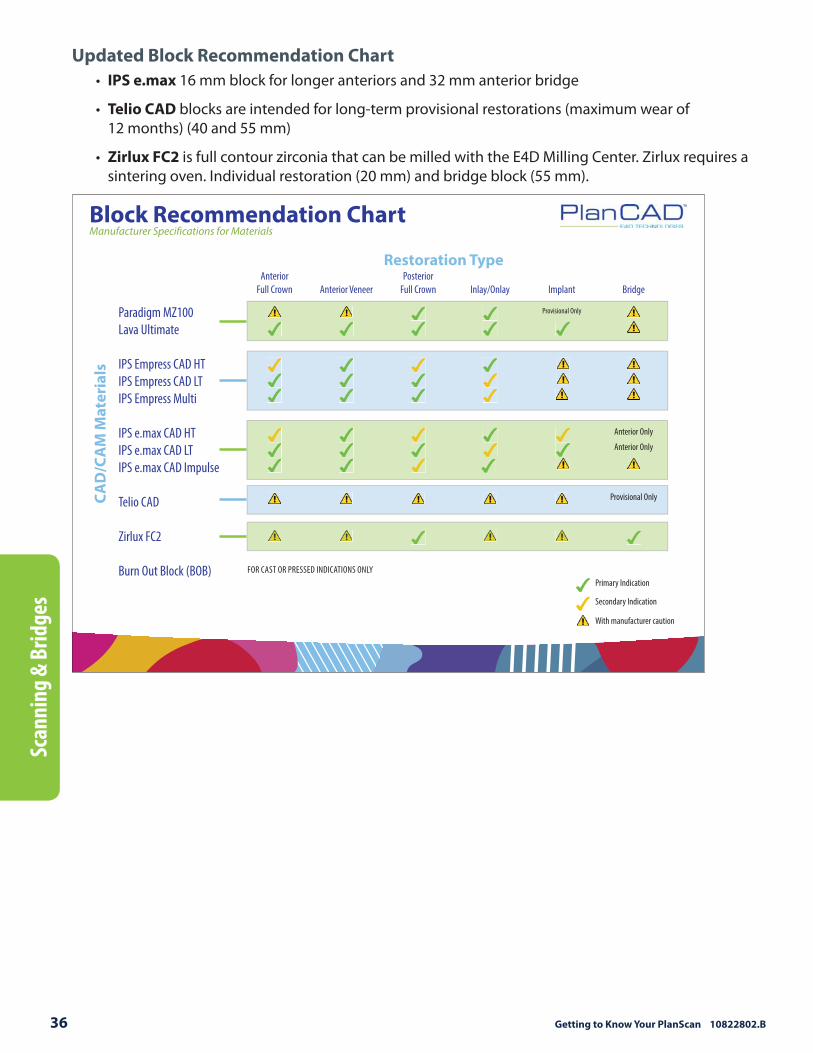
Updated Block Recommendation Chart
• IPS e.max 16 mm block for longer anteriors and 32 mm anterior bridge
• Telio CAD blocks are intended for long-term provisional restorations (maximum wear of 12 months) (40 and 55 mm)
• Zirlux FC2 is full contour zirconia that can be milled with the E4D Milling Center. Zirlux requires a sintering oven. Individual restoration (20 mm) and bridge block (55 mm).
FOR CAST OR PRESSED INDICATIONS ONLY
Paradigm MZ100
Lava Ultimate
IPS Empress CAD HT
IPS Empress CAD LT
IPS Empress Multi
IPS e.max CAD HT
IPS e.max CAD LT
IPS e.max CAD Impulse
Telio CAD
Zirlux FC2
Burn Out Block (BOB)
Restoration Type
CAD
/CA
M M
ater
ials
Anterior
Full Crown Anterior Veneer
Posterior
Full Crown Inlay/Onlay Implant Bridge
Provisional Only
Anterior Only
Anterior Only
Provisional Only
Primary Indication
Secondary Indication
With manufacturer caution
Block Recommendation ChartManufacturer Specifi cations for Materials
Customer Support 800.537.6070 37
Scann
ing &
Bridges
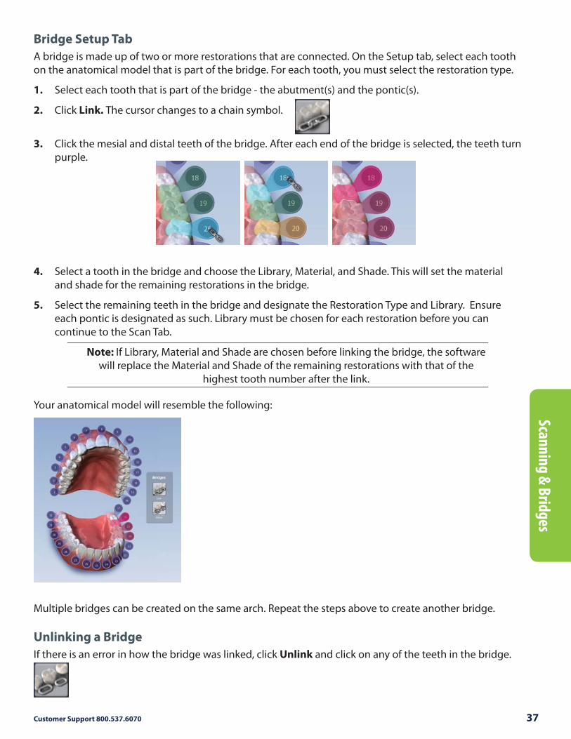
Bridge Setup Tab
A bridge is made up of two or more restorations that are connected. On the Setup tab, select each tooth on the anatomical model that is part of the bridge. For each tooth, you must select the restoration type.
1. Select each tooth that is part of the bridge - the abutment(s) and the pontic(s).
2. Click Link. The cursor changes to a chain symbol.
3. Click the mesial and distal teeth of the bridge. After each end of the bridge is selected, the teeth turn purple.
4. Select a tooth in the bridge and choose the Library, Material, and Shade. This will set the material and shade for the remaining restorations in the bridge.
5. Select the remaining teeth in the bridge and designate the Restoration Type and Library. Ensure each pontic is designated as such. Library must be chosen for each restoration before you can continue to the Scan Tab.
Note: If Library, Material and Shade are chosen before linking the bridge, the software will replace the Material and Shade of the remaining restorations with that of the
highest tooth number after the link.
Your anatomical model will resemble the following:
Multiple bridges can be created on the same arch. Repeat the steps above to create another bridge.
Unlinking a Bridge
If there is an error in how the bridge was linked, click Unlink and click on any of the teeth in the bridge.

38 Getting to Know Your PlanScan 10822802.B
Scan
nin
g &
Bri
dges
Bridge Scanning
The scanning procedure for a bridge is the same as that for a multiple restoration case. Scan the prepped teeth, the edentulous area, and two or more unprepped neighbors to aid in design and alignment.
Note that scanning more teeth on anterior bridges will aid in the smile design.
Bridge Orientation
Set the Orientation for each tooth tab. Good model alignment will aid Autogenesis with the design and is important for the bridge’s Path of Insertion.

Customer Support 800.537.6070 39
Scann
ing &
Bridges
Drawing Pontic Margins
A margin is drawn for each tooth in the bridge.
1. Click the tooth number tab for each abutment and draw the margin on the selected tooth.
An edentulous space does not technically have a margin. The margin is drawn on the gingival tissue to aid the design process.
2. Click Trace and designate the position and extension of the base of the pontic on the gingival tissue to fi t the appropriate contour.
Note: Do not go too far down the curve of the gingival tissue or you
may not be able to fi t the bridge in the block.
40 Getting to Know Your PlanScan 10822802.B
Scan
nin
g &
Bri
dges
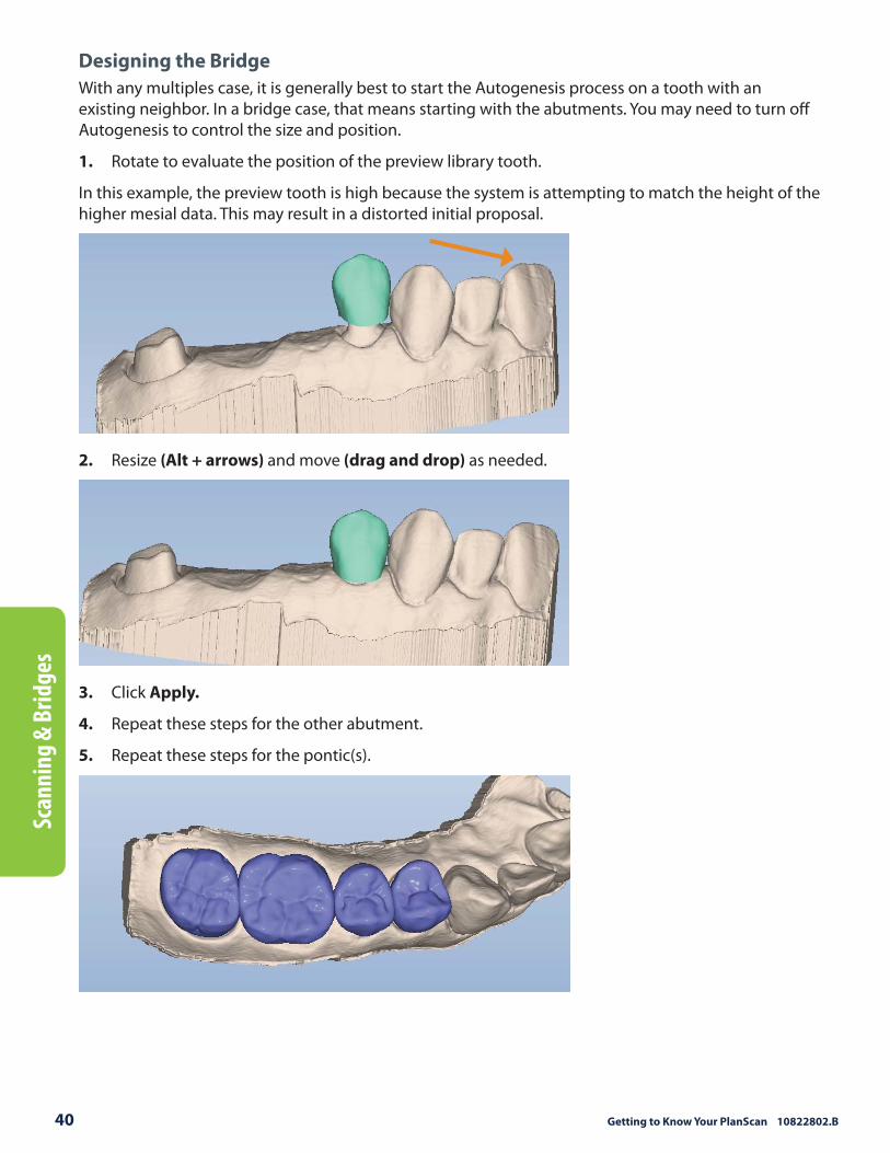
Designing the Bridge
With any multiples case, it is generally best to start the Autogenesis process on a tooth with an existing neighbor. In a bridge case, that means starting with the abutments. You may need to turn off Autogenesis to control the size and position.
1. Rotate to evaluate the position of the preview library tooth.
In this example, the preview tooth is high because the system is attempting to match the height of the higher mesial data. This may result in a distorted initial proposal.
2. Resize (Alt + arrows) and move (drag and drop) as needed.
3. Click Apply.
4. Repeat these steps for the other abutment.
5. Repeat these steps for the pontic(s).

Customer Support 800.537.6070 41
Scann
ing &
Bridges
When you rotate the model, you will notice that the pontics have a solid base and are raised above the gumline (0.75 mm). The gingival aspect of the pontic follows the contours of the edentulous tissue and can be adjusted utilizing the design tools.
Note: If you are unsure whether the bridge will fi t in the desired material block, skip ahead to the Mill tab and verify that it does not say “Please reorient the restoration to fi t or try a diff erent material.” Verify and/or change your material selection in Settings. If the material is correct, try moving the sprue position. Once you are satisfi ed that the
bridge fi ts in the block, return to the Design tab to fi nish designing your bridge.
6. Follow the normal design workfl ow with interproximal contacts being the only diff erence.
7. Adjust the interproximal contacts that touch unprepped teeth to the same contact strength that you normally use.
The contacts of the bridge teeth will be fused together to form the bridge, so the actual contact strength is not a concern, but the contact should be heavy enough to ensure a proper connection.
8. When you are satisfi ed with your designs, click the Mill tab.
Spacer Tool Settings on Bridges
The default Spacer Tool settings are diff erent on bridges to account for the larger Path of Insertion.
The normal maximum for the spacer is 0.20 mm. On bridge cases, the spacer defaults to 0.20 mm and can be increased to 0.30 mm.
A larger default margin ramp of 1 mm is used to aid in stability.
Rotating Slice Plane
The Slice Plane can now be rotated. Place the center of the Slice Plane approximately where you want it and then hold down the Ctrl key while moving the mouse to rotate.

42 Getting to Know Your PlanScan 10822802.B
Scan
nin
g &
Bri
dges
Evaluating the Bridge
It is important to evaluate the connections on the bridge and look for possible hangups.
The sprue will be on the mesial or distal side of the bridge.
1. Click View Model to hide the model.
2. Click Sim.
When the Simulation is run, the connections between the teeth are displayed.
3. Click Slice Plane twice.
When Slice Plane is activated on a bridge mill simulation, the system measures the slice width. If the slice is thinner than the material guidelines, the slice displays as red. It is important to slice the simulation through the thinnest part of the connectors (yellow lines in the examples).
Posterior cases tend to have wider contacts with smaller embrasures and are unlikely to be thin. Anterior cases have smaller contacts and larger embrasures. Any thin area should be evaluated.
4. Move the Slice Plane to a connector. If the Slice Plane needs to be rotated to slice through the thinnest part, hold down the Ctrl key while moving the mouse to rotate.
5. Rotate the model to view the slice.
6. If the slice is red, adjust your embrasures and/or contacts and try the simulation again. Note that when the model is hidden, the Slice Plane icon displays the mm2 area.
Minimum required thickness:
• Zirlux FC2 - 9 mm2
• Telio CAD - 12 mm2
• IPS e.max - 16 mm2
7. Click View Model to activate it.
8. Click the Gingival View Control arrow to view the model from underneath.
9. Look for internal hangups (blue seen through the stone model on the axial walls or occlusal surface). Blue around the margin is expected due to the margin ramp. If there are any hangups, adjustments need to be made to the Spacer on the Design tab. Call Customer Support for help on your fi rst few cases if there are hangups on Bridges.

Customer Support 800.537.6070 43
Plan
Mill 40
Milling Center Changes
New Icon for a Parked Job
The Parked Job feature was introduced in Version 4.5. In this update, a new icon has been added to indicate that a job has been saved.
When a job is interrupted by an error message or a manual cancellation of the job, it is saved in Parked Job. Only the most recent job is available in Parked Job.
When a job has been saved, an icon will appear in the corner to notify you.
1. To restart the interrupted job, touch Parked Job...
2. Touch Select.
3. Reinsert the partially milled block if it had been removed.
4. Follow the on-screen instructions.
The milling restarts from where it was cancelled.
Note: Jobs interrupted by a power failure are not parked. Do NOT insert a new block for a Parked Job. A new block will
result in broken tools. To restart the job with a new block, use
Pending Jobs.

44 Getting to Know Your PlanScan 10822802.B
Pla
nM
ill 4
0Zirlux FC2 Mill Maintenance
It is necessary to clean the mill and change the water before milling Zirlux FC2. If the zirconia is contaminated with other materials, it will turn green when sintered. Cleaning after milling is recommended because the zirconia acts as a thickening agent with the water.
Zirlux FC2 Scale Factor
See the manufacturer’s Instructions for Use provided with the Zirlux FC2 blocks for processing instructions.
Zirconia shrinks in the sintering oven. There are numbers on the side of the box that the blocks come in. You must keep this box with the blocks. Do not mix blocks from diff erent boxes. Each box can have a diff erent amount of shrinking. The Milling Center asks for the Scale Factor before a Zirlux FC2 is milled. The system will increase the size of the restoration according to this number. This means you cannot test the fi t of the restoration before sintering.

Customer Support 800.537.6070 45
Appen
dix & D
ocum
ents
Appendix
This section is for people that have not previously been using Buccal/Opposing scanning. The instructions for scanning have not changed in PlanScan.
Scanning Buccal/Opposing
The opposing teeth are scanned to acquire bite information for the proposal. The buccal bite is scanned to align the preparation model with the opposing model.
Scan Opposing
Note: Many clinical operators scan the Opposing while the patient is being anesthetized.
1. On the Setup tab, Buccal/Opposing is the default.
2. On the Scan tab, select Scan Opposing.
3. Starting with an occlusal view, scan the occlusal surfaces of the opposing dentition. Include the same number of teeth as the preparation model. Ensure there is good cusp tip data on both the lingual and buccal sides.
Roll to the buccal and scan the buccal side of the opposing dentition. Include gingival data, do not stop halfway down the tooth.
46 Getting to Know Your PlanScan 10822802.B
App
endi
x &
Doc
um
ents
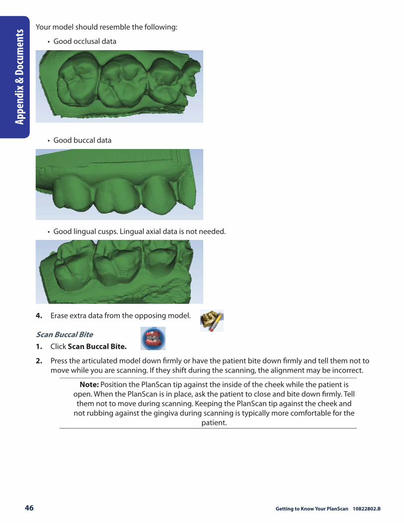
Your model should resemble the following:
• Good occlusal data
• Good buccal data
• Good lingual cusps. Lingual axial data is not needed.
4. Erase extra data from the opposing model.
Scan Buccal Bite
1. Click Scan Buccal Bite.
2. Press the articulated model down fi rmly or have the patient bite down fi rmly and tell them not to move while you are scanning. If they shift during the scanning, the alignment may be incorrect.
Note: Position the PlanScan tip against the inside of the cheek while the patient is open. When the PlanScan is in place, ask the patient to close and bite down fi rmly. Tell them not to move during scanning. Keeping the PlanScan tip against the cheek and
not rubbing against the gingiva during scanning is typically more comfortable for the patient.

Customer Support 800.537.6070 47
Appen
dix & D
ocum
ents
3. Scan at a 90° angle to the teeth. Scan the sides of the teeth that were captured in the preparation and opposing models. Ensure some gingival data is captured.
4. Click Generate Model or press M on the keyboard. The system generates the model and attempts to align to the other scanned models. The software should automatically align the models. If Align Buccal is red, see previous for instructions on manually “Model Alignment.”
Your model should resemble the following. Ensure there is good data on the buccal sides of the teeth. Intraoral scans will most likely have the tongue in the background. Model scans will have space fi ller in the gaps.
5. Erase any excess data from the model.
New Documentation Available
PlanScan documentation and videos available at the Learning Tools
on www.e4d.com home page (lower right corner).
W
eek 1 W
eek 2 W
eek 3 W
eek 4 W
eek 5
Water
Strainer
Collets
MO
NTH
1
MO
NTH
3
MO
NTH
2
MO
NTH
4
HSD
Q
uarterly
W
eek 1 W
eek 2 W
eek 3 W
eek 4 W
eek 5
Water
Strainer
Collets
W
eek 1 W
eek 2 W
eek 3 W
eek 4 W
eek 5
Water
Strainer
Collets
W
eek 1 W
eek 2 W
eek 3 W
eek 4 W
eek 5
Water
Strainer
Collets
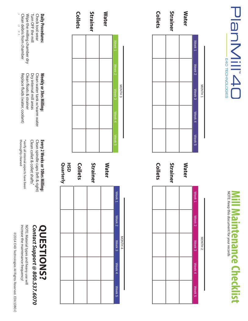
Daily Procedures:Check tool w
earTurn O
FF the mill
Wipe the m
illing chamber dry
Clean debris from cham
berL
thlid
QU
ESTION
S?Contact Support @
800.537.6070N
OTE: M
aterial types and heavy use will
increase the maintenance frequency!
Weekly or 3hrs M
illing:Clean w
ater tank w/w
arm w
aterD
ry internal mill areas
Clean fl oats & strainer
Replace fl uids (water, coolant)
Every 2 Weeks or 10hrs M
illing:Clean spindle caps (left &
right)Clean collet &
collet shafts *
*verify all internal aspects have been thoroughly cleaned
Mill M
aintenance ChecklistN
OTE: Keep this docum
ent for your records
©2
014 E4
D Technologies All R
ights Reserved. ED
U10
80
.C

© 2
014
E4D
Tech
nolo
gies
All
Righ
ts R
eser
ved
EDU
1113
.A
• St
art o
n th
e sa
me
side
as
the
initi
al s
egm
ent
• A
full
arch
bite
is n
ot
nece
ssar
y
Bucc
al B
ite
Qu
ad
ran
t &
Fu
ll A
rch
Sc
an
nin
g T
ec
hn
iqu
es
Tips &
Patte
rns
Quad
rant
Scan
ning
• U
se o
f an
intr
aora
l ret
ract
ion
devi
ce
is a
dvis
ed fo
r sca
nnin
g. It
is c
ritic
al
in th
e an
terio
r seg
men
t.
• Th
e st
artin
g po
int s
houl
d be
dire
ctly
ov
er th
e oc
clus
al s
urfa
ce. T
his
sets
th
e or
ient
atio
n of
the
mod
el.
• A
fter
pas
sing
the
mid
line
on
ante
rior s
egm
ents
, you
may
wan
t to
cha
nge
the
wan
d’s
orie
ntat
ion
or
“fl ip
” to
cont
inue
sca
nnin
g.
Post
erio
r Seg
men
tsAn
terio
r Seg
men
ts
Begi
n sc
anni
ng th
e po
ster
ior s
egm
ent
usin
g th
e sc
an p
atte
rn s
how
n ab
ove.
U
se fu
ll ro
tatio
ns a
nd li
mit
exce
ss d
ata;
su
ch a
s th
e ch
eek
or to
ngue
.
The
sadd
le te
chni
que
is u
sed
in th
e an
terio
r reg
ion.
Rol
l fro
m th
e fa
cial
to th
e lin
gual
in s
mal
l, gr
adua
l mov
emen
ts. A
fter
pas
sing
the
mid
line,
you
can
fl ip
the
scan
ner p
ositi
on to
con
tinue
. Sev
eral
pas
ses
from
faci
al to
ling
ual,
lingu
al to
fa
cial
will
be
need
ed to
com
plet
e th
e sc
an. R
emem
ber t
o st
art d
irect
ly o
ver t
he
inci
sal e
dge.
NO
TE: W
hen
fl ipp
ing,
be
sure
to o
verla
p th
e da
ta st
artin
g fro
m th
e lin
gual
asp
ect.
Begi
n sc
anni
ng o
n th
e m
ost d
ista
l too
th
in th
e ar
ch. M
ove
in a
ser
pent
ine
scan
pa
tter
n as
sho
wn
tow
ard
the
ante
rior
regi
on. B
e su
re to
sta
rt s
cann
ing
in th
e sa
me
area
as
the
initi
al s
can.
Use
thes
e st
ep fo
r all
quad
rant
scan
ning
: pre
-op,
pr
ep, a
nd o
ppos
ing.

Qu
ad
ran
t & F
ull A
rch
Sc
an
nin
g T
ec
hn
iqu
eTips & Patterns
Full Arch Scanning•
Begin scanning over the occlusal surface of the m
ost distal tooth. The fi rst scan sets the orientation of the entire m
odel.
• Rotate to the lingual and then to the facial for each tooth. This w
ill give you the best accuracy w
hile scanning.
• For Full A
rch scanning, fl ipping the scanner after passing the m
idline w
ill be crucial. The data must
overlap in the “fl ip zone”.
Start directly over the occlusal surface, rotate to the lingual
From the lingual rotate to the
buccalRotate to the lingual of the neighbor and continue scanning from
lingual to buccal for each tooth
Using the saddle technique throughout
the arch will ensure an accurate m
odel. After passing the m
idline, fl ip the scanner. Be sure to overlap the data.
Flip Zone
© 2014 E4D
Technologies A
ll Rights Reserved EDU
1113.A
Repeat these steps for the opposing arch. Rem
ember to
capture the bite.
See the other page of this document for
the buccal bite scanning technique.

© 2
014
E4
D T
echn
olog
ies
All
Rig
hts
Res
erve
d ED
U11
07.A
Impr
essio
ns
Not
e: In
form
atio
n on
sca
nnin
g Bi
te R
egis
trat
ion
mat
eria
l can
be
foun
d in
the
Use
r Man
ual
Capt
ure
the
bucc
al s
urfa
ce o
f th
e de
ntiti
on in
the
prep
and
op
posi
ng
2-3
mm
gin
giva
l tis
sue
No
rota
tions
nec
essa
ry
Bucc
al B
iteOp
posin
g10
0% o
f the
cus
ps
2-3
mm
gin
giva
l tis
sue
on th
e bu
ccal
sid
e
Ling
ual a
nd g
ingi
val d
ata
not
nece
ssar
y
100%
of t
he p
rep
and
inte
rpro
xim
al c
onta
ct a
reas
90%
of t
he a
djac
ent t
eeth
Goo
d ax
ial d
ata
for d
esig
n
2-3
mm
gin
giva
l tis
sue
on
bucc
al a
nd li
ngua
l
Sca
nnin
g Te
chni
que
Go
als
& P
atte
rns
Prep
arat
ion
100%
of t
he p
rep
and
inte
rpro
xim
al c
onta
ct a
reas
90%
of t
he a
djac
ent t
eeth
Goo
d ax
ial d
ata
for d
esig
n
2-3
mm
gin
giva
l tis
sue
on
bucc
al a
nd li
ngua
l
Inte
rpro
xim
alTo
ach
ieve
100
% o
f the
in
terp
roxi
mal
con
tact
are
a, a
sl
ight
rota
tion
of th
e sc
anne
r w
ill b
e ne
eded
Rest
the
scan
ner o
n th
e pr
oxim
al d
entit
ion
and
perp
endi
cula
r to
the
arch

SCAN
MAR
GIN
DESI
GNM
ILL
Bucc
al B
ite S
cann
ing
Scan
Pre
p10
0%
of P
rep
and
cont
acts
Verif
ying
the
appr
opria
te a
mou
nt
of s
can
data
will
ens
ure
a be
tter
fit
ting
rest
orat
ion.
!
Ori
enta
tion
Auto
mat
ical
ly a
ctiv
e; u
se th
e Vi
ew C
ircle
to p
ositi
on m
odel
Trac
e M
argi
nFr
om th
e oc
clus
al v
iew
, mar
k th
e m
argi
n on
the
shou
lder
Toot
h Li
brar
ies
Aut
ogen
esis
™ O
N -
Clic
k A
PPLY
Aut
ogen
esis
OFF
- Re
size
, Rep
ositi
on, R
e-A
pply
Incr
emen
tal T
ools
Larg
e ad
just
men
ts to
toot
h po
sitio
n - F
ittin
g th
e pr
opos
al in
its
spac
e
Free
form
Cha
nge
Tool
sSm
all a
djus
tmen
ts to
con
tour
- Fi
ne tu
ning
the
desi
gn
Mat
eria
l Thi
ckne
ssO
cclu
sal t
able
- 1.
5 to
2 m
m (D
ark
Gre
en/B
lue)
Axi
al w
alls
- 1.
0 to
1.5
mm
(Gre
en)
Mar
gins
- Ye
llow
Rubb
er T
ooth
1st -
Axi
al W
alls
2nd
- Mar
gina
l Rid
ges
(Occ
lusa
l Tab
le if
nee
ded)
3rd
- Em
bras
ures
Adju
stin
g th
e Bi
teAc
tivat
e Vi
ew B
ite
Regi
stra
tion
(clic
k tw
ice)
th
en a
ctiv
ate
View
Con
tact
s to
eva
luat
e.
Use
Con
tact
Ref
inem
ent (
smal
l circ
les)
to
adju
st to
Whi
te, B
row
n, B
lack
.
Adju
stin
g In
terp
roxi
mal
Con
tact
s
Rech
eck
Mat
eria
l Thi
ckne
ss &
Che
ck M
argi
nsVe
rify
that
des
ign
chan
ges
have
not
affe
cted
the
appr
opria
te
mat
eria
l thi
ckne
ss fo
r mill
ing.
Turn
OFF
Vie
w B
ite
Regi
stra
tion
and
act
ivat
e H
ide
Mod
el. R
otat
e to
the
mes
ial a
nd d
ista
l to
eval
uate
in
terp
roxi
mal
con
tact
s. Re
turn
to F
reef
orm
Cha
nge
Tool
s, u
se S
moo
th S
urfa
ce to
adj
ust t
o Li
ght G
reen
/Aq
ua s
urro
unde
d by
Dar
k Bl
ue.
Mar
gins
sho
uld
be Y
ello
w. I
f Red
/Ora
nge,
ver
ify
mar
gin
plac
emen
t with
Mov
e M
argi
n. U
se
Dro
pper
as
need
ed to
add
mat
eria
l.
Spru
e Po
sitio
nAw
ay fr
om m
argi
ns,
cont
acts
, and
occ
lusi
on.
Initi
al p
ositi
on is
the
fast
est
mill
ing
time.
Ver
ify th
e en
d of
the
spru
e is
roun
d.
Mill
Sim
Chec
k th
e in
tern
al fi
t of y
our
rest
orat
ion
befo
re m
illin
g.
Bloc
k Si
ze S
elec
tion
Avai
labl
e bl
ock
size
s de
pend
on
spru
e po
sitio
n an
d th
e m
ater
ial s
elec
ted.
Cong
ratu
latio
ns!
Brig
ht Y
ello
w o
n th
e oc
clus
al o
r ax
ial s
urfa
ces
indi
cate
s lo
w m
ater
ial
thic
knes
s an
d sh
ould
be
adju
sted
in
the
Des
ign
tab.
!U
se th
e Er
aser
tool
to
rem
ove
exce
ss s
can
data
Scan
Buc
cal
Capt
ure
all t
eeth
ass
ocia
ted
in P
rep
& O
ppos
ing
scan
s
Verif
y bu
ccal
alig
nmen
t, an
d re
-alig
n if
need
ed
Scan
Opp
osin
g10
0% O
cclu
sal a
nd 2
mm
of
bucc
al g
ingi
val d
ata
Clic
k D
ata
Den
sity
Vie
w
to e
valu
ate
for l
ow d
ata
Clic
k S
how
Fea
ture
s as
an
aid
to h
ighl
ight
hig
h co
ntou
r are
as
Use
Mov
e M
argi
n to
ad
just
pla
cem
ent
Use
Add
Seg
men
ts to
re
draw
a p
ortio
n
©20
14 E
4D Te
chno
logi
es
All
Righ
ts R
eser
ved.
ED
U11
03.A
Aft
er d
eact
ivat
ing
all t
ools
, us
e th
e gr
een
Prev
iew
Toot
h to
ver
ify o
rient
atio
n.
CAD/
CAM
Wor
kfl o
wQU
ESTI
ONS
ABOU
T DE
SIGN
? Con
tact
Sup
port
@ 8
00.5
37.6
070
ICE
mod
e ca
n be
use
d in
m
argi
n de
tect
ion;
rem
embe
r st
one
mod
e is
prio
rity
Ori
enta
tion
Gui
de
Mar
gin
Mar
king
Gui
de
Occ
lusa
l - B
ucca
l/Lin
gual
tip
Dis
tal -
Alig
n bu
ccal
cus
psBu
ccal
- M
argi
nal r
idge
s