gevers aircraft, inc. genesis aircraft, inc. genesis ... the added water & snow capabilities...
TRANSCRIPT
GEVERS AIRCRAFT, INC.GENESIS
Gevers Aircraft, Inc.PO Box 430
Brownsburg, Indiana 46112 USA317-852-2735
INTRODUCTIONThe only high performance aircraft that can takeoff and land on snow, water, and hard
surface! Unique designs of Multipurpose Landing Gear, Telescopic Wing, and InterconnectedPropeller system provide increased utility, performance, and safety.
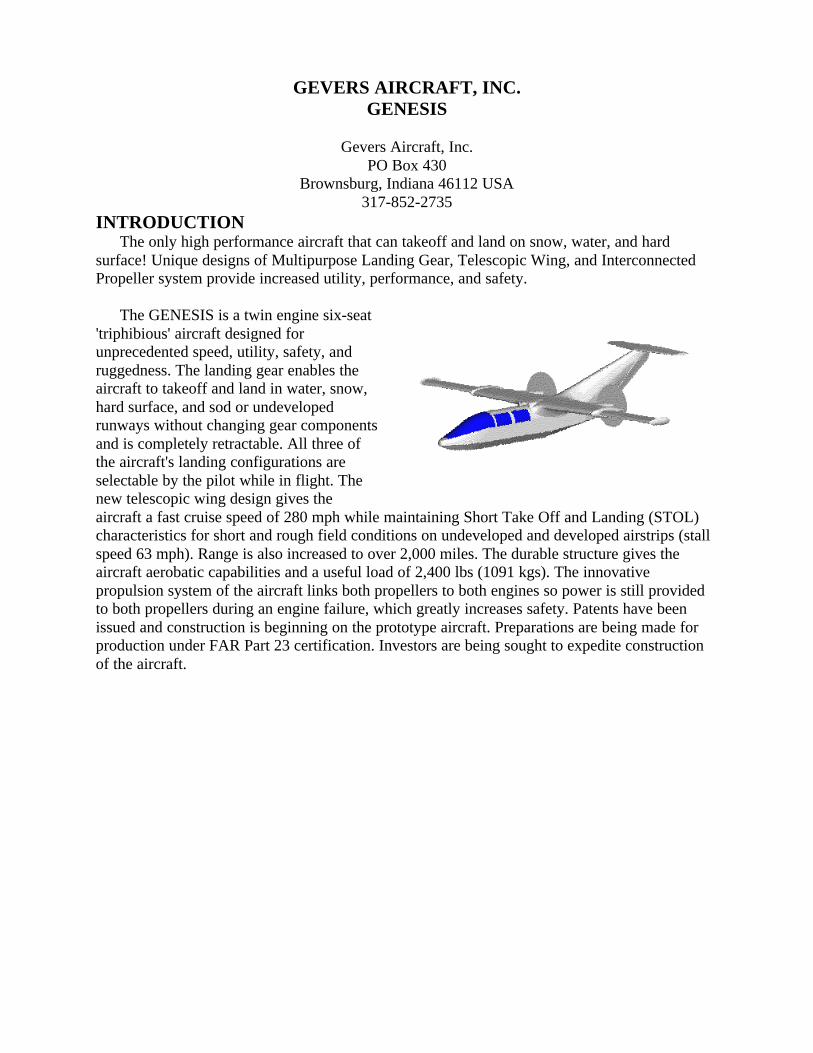
The GENESIS is a twin engine six-seat'triphibious' aircraft designed forunprecedented speed, utility, safety, andruggedness. The landing gear enables theaircraft to takeoff and land in water, snow,hard surface, and sod or undevelopedrunways without changing gear componentsand is completely retractable. All three ofthe aircraft's landing configurations areselectable by the pilot while in flight. Thenew telescopic wing design gives theaircraft a fast cruise speed of 280 mph while maintaining Short Take Off and Landing (STOL)characteristics for short and rough field conditions on undeveloped and developed airstrips (stallspeed 63 mph). Range is also increased to over 2,000 miles. The durable structure gives theaircraft aerobatic capabilities and a useful load of 2,400 lbs (1091 kgs). The innovativepropulsion system of the aircraft links both propellers to both engines so power is still providedto both propellers during an engine failure, which greatly increases safety. Patents have beenissued and construction is beginning on the prototype aircraft. Preparations are being made forproduction under FAR Part 23 certification. Investors are being sought to expedite constructionof the aircraft.
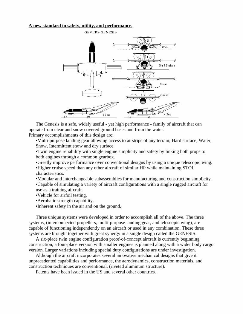
A new standard in safety, utility, and performance.
The Genesis is a safe, widely useful - yet high performance - family of aircraft that canoperate from clear and snow covered ground bases and from the water.Primary accomplishments of this design are:
•Multi-purpose landing gear allowing access to airstrips of any terrain; Hard surface, Water,Snow, Intermittent snow and dry surface.•Twin engine reliability with single engine simplicity and safety by linking both props toboth engines through a common gearbox.•Greatly improve performance over conventional designs by using a unique telescopic wing.•Higher cruise speed than any other aircraft of similar HP while maintaining STOLcharacteristics.•Modular and interchangeable subassemblies for manufacturing and construction simplicity.•Capable of simulating a variety of aircraft configurations with a single rugged aircraft foruse as a training aircraft.•Vehicle for airfoil testing.•Aerobatic strength capability.•Inherent safety in the air and on the ground.
Three unique systems were developed in order to accomplish all of the above. The threesystems, (interconnected propellers, multi-purpose landing gear, and telescopic wing), arecapable of functioning independently on an aircraft or used in any combination. These threesystems are brought together with great synergy in a single design called the GENESIS.
A six-place twin engine configuration proof-of-concept aircraft is currently beginningconstruction, a four-place version with smaller engines is planned along with a wider body cargoversion. Larger variations including special duty configurations are under investigation.
Although the aircraft incorporates several innovative mechanical designs that give itunprecedented capabilities and performance, the aerodynamics, construction materials, andconstruction techniques are conventional, (riveted aluminum structure).
Patents have been issued in the US and several other countries.
MULTI-CONFIGURATION LANDING GEAR (TRIPHIBIOUS)Convertible in flight between wheels, skis, and amphibious hull.
The ability to takeoff & land on hard surface, water, snow, and intermittent snow coveredrunways gives the Genesis high utility capabilities. All landing configurations are selectablefrom the cockpit in flight without the need to change gear components on the ground.
Description:
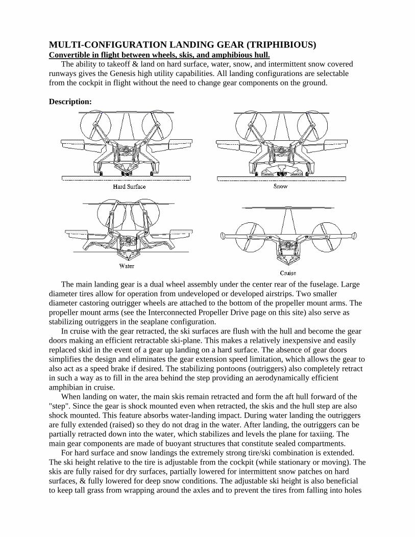
The main landing gear is a dual wheel assembly under the center rear of the fuselage. Largediameter tires allow for operation from undeveloped or developed airstrips. Two smallerdiameter castoring outrigger wheels are attached to the bottom of the propeller mount arms. Thepropeller mount arms (see the Interconnected Propeller Drive page on this site) also serve asstabilizing outriggers in the seaplane configuration.
In cruise with the gear retracted, the ski surfaces are flush with the hull and become the geardoors making an efficient retractable ski-plane. This makes a relatively inexpensive and easilyreplaced skid in the event of a gear up landing on a hard surface. The absence of gear doorssimplifies the design and eliminates the gear extension speed limitation, which allows the gear toalso act as a speed brake if desired. The stabilizing pontoons (outriggers) also completely retractin such a way as to fill in the area behind the step providing an aerodynamically efficientamphibian in cruise.
When landing on water, the main skis remain retracted and form the aft hull forward of the"step". Since the gear is shock mounted even when retracted, the skis and the hull step are alsoshock mounted. This feature absorbs water-landing impact. During water landing the outriggersare fully extended (raised) so they do not drag in the water. After landing, the outriggers can bepartially retracted down into the water, which stabilizes and levels the plane for taxiing. Themain gear components are made of buoyant structures that constitute sealed compartments.
For hard surface and snow landings the extremely strong tire/ski combination is extended.The ski height relative to the tire is adjustable from the cockpit (while stationary or moving). Theskis are fully raised for dry surfaces, partially lowered for intermittent snow patches on hardsurfaces, & fully lowered for deep snow conditions. The adjustable ski height is also beneficialto keep tall grass from wrapping around the axles and to prevent the tires from falling into holes
or deep ruts. Both the nose and main gear have the same basic mechanism forextension/retraction, support, and energy absorption and are completely retractable in flight.
For those pilots operating strictly from developed land bases there is no penalty for havingthe added water & snow capabilities since the entire gear assembly is a simple rugged designwhich completely retracts into the aerodynamic hull.
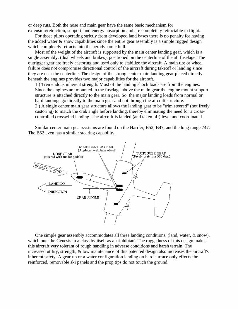
Most of the weight of the aircraft is supported by the main center landing gear, which is asingle assembly, (dual wheels and brakes), positioned on the centerline of the aft fuselage. Theoutrigger gear are freely castoring and used only to stabilize the aircraft. A main tire or wheelfailure does not compromise directional control of the aircraft during takeoff or landing sincethey are near the centerline. The design of the strong center main landing gear placed directlybeneath the engines provides two major capabilities for the aircraft.
1.) Tremendous inherent strength. Most of the landing shock loads are from the engines.Since the engines are mounted in the fuselage above the main gear the engine mount supportstructure is attached directly to the main gear. So, the major landing loads from normal orhard landings go directly to the main gear and not through the aircraft structure.2.) A single center main gear structure allows the landing gear to be "trim steered" (not freelycastoring) to match the crab angle before landing, thereby eliminating the need for a cross-controlled crosswind landing. The aircraft is landed (and taken off) level and coordinated.
Similar center main gear systems are found on the Harrier, B52, B47, and the long range 747.The B52 even has a similar steering capability.
One simple gear assembly accommodates all three landing conditions, (land, water, & snow),which puts the Genesis in a class by itself as a 'triphibian'. The ruggedness of this design makesthis aircraft very tolerant of rough handling in adverse conditions and harsh terrain. Theincreased utility, strength, & low maintenance of this patented design also increases the aircraft'sinherent safety. A gear-up or a water configuration landing on hard surface only effects thereinforced, removable ski panels and the prop tips do not touch the ground.
Cockpit Controls:Although the landing gear has several configurations - dry land, snow, intermittent snow/dry
land, water, and retracted, the control is simple. A single multi-position lever is used to select thedesired configuration. The configuration must be selected each time the gear is extended. Thiseliminates the complexity of having separate selectors for extend/retract and configuration. Thepilot can visually check the position of all configurations by looking out the window over hisshoulder and also by conventional position lights on the instrument panel. There is no maximumgear extend or retract speed so the gear can be used as speed brakes.
Both the nose and main gear are steerable. The nose wheel is steerable by using the rudderpedals and the main is steerable from a trim switch.
Advantages:•The landing gear is reconfigurable in flight between water, snow, and hard surfaces - nomodifications required.•The amphibious hull is strong and absorbs energy during hard landings.•The gear can be converted from wheels to skis and vice-versa while stationary or moving onboth snow and dry surface.•The skis can be partially lowered around the wheels to lift the wheels over intermittent snowpatches, to keep tall grass from wrapping around the axles and to prevent the tires fromfalling into holes.•The outrigger arms can be partially lowered to provide a stable water taxi configuration.•The entire landing gear is extremely rugged and easily maintained.•Landing shock loads from engine weight do not stress the wing or fuselage structure.•A main tire, wheel, or brake failure does not compromise directional control of the aircraftduring takeoff or landing.•The steerable center gear virtually eliminates crosswind landing limitations.•Landing and takeoff in crosswind conditions is done with coordinated controls.
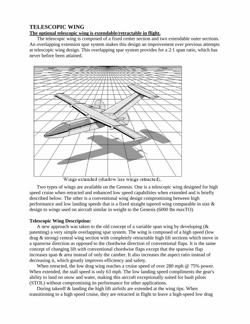
TELESCOPIC WINGThe optional telescopic wing is extendable/retractable in flight.
The telescopic wing is composed of a fixed center section and two extendable outer sections.An overlapping extension spar system makes this design an improvement over previous attemptsat telescopic wing design. This overlapping spar system provides for a 2:1 span ratio, which hasnever before been attained.
Two types of wings are available on the Genesis. One is a telescopic wing designed for highspeed cruise when retracted and enhanced low speed capabilities when extended and is brieflydescribed below. The other is a conventional wing design compromising between highperformance and low landing speeds that is a fixed straight tapered wing comparable in size &design to wings used on aircraft similar in weight to the Genesis (6000 lbs maxTO).
Telescopic Wing Description:A new approach was taken to the old concept of a variable span wing by developing (&
patenting) a very simple overlapping spar system. The wing is composed of a high speed (lowdrag & strong) central wing section with completely retractable high lift sections which move ina spanwise direction as opposed to the chordwise direction of conventional flaps. It is the sameconcept of changing lift with conventional chordwise flaps except that the spanwise flapincreases span & area instead of only the camber. It also increases the aspect ratio instead ofdecreasing it, which greatly improves efficiency and safety.
When retracted, the low drag wing reaches a cruise speed of over 280 mph @ 75% power.When extended, the stall speed is only 63 mph. The low landing speed compliments the gear'sability to land on snow and water, making this aircraft exceptionally suited for bush pilots(STOL) without compromising its performance for other applications.
During takeoff & landing the high lift airfoils are extended at the wing tips. Whentransitioning to a high speed cruise, they are retracted in flight to leave a high-speed low drag

wing capable of withstanding high 'g' loads. This system is simple, rugged, and fail-safe. Theaircraft can also maneuver in flight and land safely with the wings in any position from fullyextended through fully retracted. The extension/retraction mechanism is a simple system ofcables that prevents asymmetric extension. Redundancy is built in so that failure of any cabledoes not hinder safe operation. Ailerons are on both the center section and extendable sectionsand are fully functional at all times during the extension/retraction process. The airfoils areconventional NACA sections.
The mechanism is simple and reliable. The extendable section spars interlock and are guidedon rollers to increase the span. Binding under load during transition is prevented by the details ofthe roller system. This design is actually simpler than conventional high lift devices.
The overall weight of this wing is comparable to that of a conventional compromise wing fora similar size aircraft that is required to produce the same speed range, however, it is strongerand more efficient than the conventional wing. When retracted, this wing's strength puts it in anAerobatic category (6.0 g's), and when extended, it is in the Normal category (3.8 g's).
Comparison of conventional and telescopic wings:This is a simplified comparison of conventional and telescopic wings to show the concepts
involved. Conventional flaps and other high lift devices can be applied to both wing types withequal effects.
Weight: In order for the conventional wing to match the low stall speed of the telescopic wing, itwould need a planform area and span similar to the extended telescopic wing (which is relativelylarge). As speed is increased, less wing area is needed to produce the required lift. So, for thisconventional wing, at high speeds there is a lot more wing exposed to the high aerodynamicloads than is required. For this large conventional wing to be strong enough to reach the highcruise speeds that the retracted telescopic wing can achieve, it must be exceptionally strong,which means a heavy structure. The telescopic wing, on the other hand, has only the inboardwing section (1/2 of the span) exposed to the high aerodynamic forces in cruise, which reducesstructural weight. Since retractable high lift devices such as flaps and the extendable wingsections are only used at low speeds, they do not need to withstand the high aerodynamic forcesthat exist at cruise speeds and they can be made lighter. Because a conventional wing is acompromise between the large low speed wing and the short high-speed wing its performance isalso compromised. The telescopic wing does not compromise its performance and can reachlower stall speeds and higher cruise speeds than the conventional compromise wing. Thetelescopic wing, including the telescoping mechanism (rollers, cables, etc.), is actually lighterthan a conventional wing that reaches the same stall and cruise speeds. A conventionalcompromise wing can be built slightly lighter than the telescopic wing but it would not have thelow stall speed or the tremendous strength at high speeds that the telescopic wing has.
Complexity: A conventional compromise wing uses flaps and sometimes movable slats to reducethe stall speed to that of the telescopic wing. The Gevers telescopic wing actually has fewercritical moving parts than a complex fowler flap does. A component failure is less likely to occurin the telescopic wing and if it does, components are redundant and the design is also fail-safe.Redundancy means that a single component failure such as an extension cable breaking does notaffect the actuation of the wing. Fail-safe means that if multiple components fail the wings willsimply stop in the current position. If this occurs, the aircraft can still fly, land, and maneuverwith the wings in any position. Asymmetric extension is prevented by the design more so thanwith some conventional flaps. So the Gevers telescopic design is simple and safe.
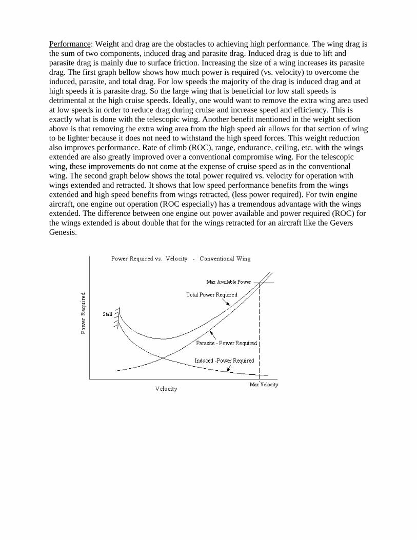
Performance: Weight and drag are the obstacles to achieving high performance. The wing drag isthe sum of two components, induced drag and parasite drag. Induced drag is due to lift andparasite drag is mainly due to surface friction. Increasing the size of a wing increases its parasitedrag. The first graph bellow shows how much power is required (vs. velocity) to overcome theinduced, parasite, and total drag. For low speeds the majority of the drag is induced drag and athigh speeds it is parasite drag. So the large wing that is beneficial for low stall speeds isdetrimental at the high cruise speeds. Ideally, one would want to remove the extra wing area usedat low speeds in order to reduce drag during cruise and increase speed and efficiency. This isexactly what is done with the telescopic wing. Another benefit mentioned in the weight sectionabove is that removing the extra wing area from the high speed air allows for that section of wingto be lighter because it does not need to withstand the high speed forces. This weight reductionalso improves performance. Rate of climb (ROC), range, endurance, ceiling, etc. with the wingsextended are also greatly improved over a conventional compromise wing. For the telescopicwing, these improvements do not come at the expense of cruise speed as in the conventionalwing. The second graph below shows the total power required vs. velocity for operation withwings extended and retracted. It shows that low speed performance benefits from the wingsextended and high speed benefits from wings retracted, (less power required). For twin engineaircraft, one engine out operation (ROC especially) has a tremendous advantage with the wingsextended. The difference between one engine out power available and power required (ROC) forthe wings extended is about double that for the wings retracted for an aircraft like the GeversGenesis.
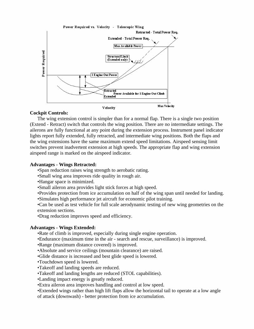
Cockpit Controls:The wing extension control is simpler than for a normal flap. There is a single two position
(Extend - Retract) switch that controls the wing position. There are no intermediate settings. Theailerons are fully functional at any point during the extension process. Instrument panel indicatorlights report fully extended, fully retracted, and intermediate wing positions. Both the flaps andthe wing extensions have the same maximum extend speed limitations. Airspeed sensing limitswitches prevent inadvertent extension at high speeds. The appropriate flap and wing extensionairspeed range is marked on the airspeed indicator.
Advantages - Wings Retracted:•Span reduction raises wing strength to aerobatic rating.•Small wing area improves ride quality in rough air.•Hangar space is minimized.•Small aileron area provides light stick forces at high speed.•Provides protection from ice accumulation on half of the wing span until needed for landing.•Simulates high performance jet aircraft for economic pilot training.•Can be used as test vehicle for full scale aerodynamic testing of new wing geometries on theextension sections.•Drag reduction improves speed and efficiency.
Advantages - Wings Extended:•Rate of climb is improved, especially during single engine operation.•Endurance (maximum time in the air - search and rescue, surveillance) is improved.•Range (maximum distance covered) is improved.•Absolute and service ceilings (mountain clearance) are raised.•Glide distance is increased and best glide speed is lowered.•Touchdown speed is lowered.•Takeoff and landing speeds are reduced.•Takeoff and landing lengths are reduced (STOL capabilities).•Landing impact energy is greatly reduced.•Extra aileron area improves handling and control at low speed.•Extended wings rather than high lift flaps allow the horizontal tail to operate at a low angleof attack (downwash) - better protection from ice accumulation.
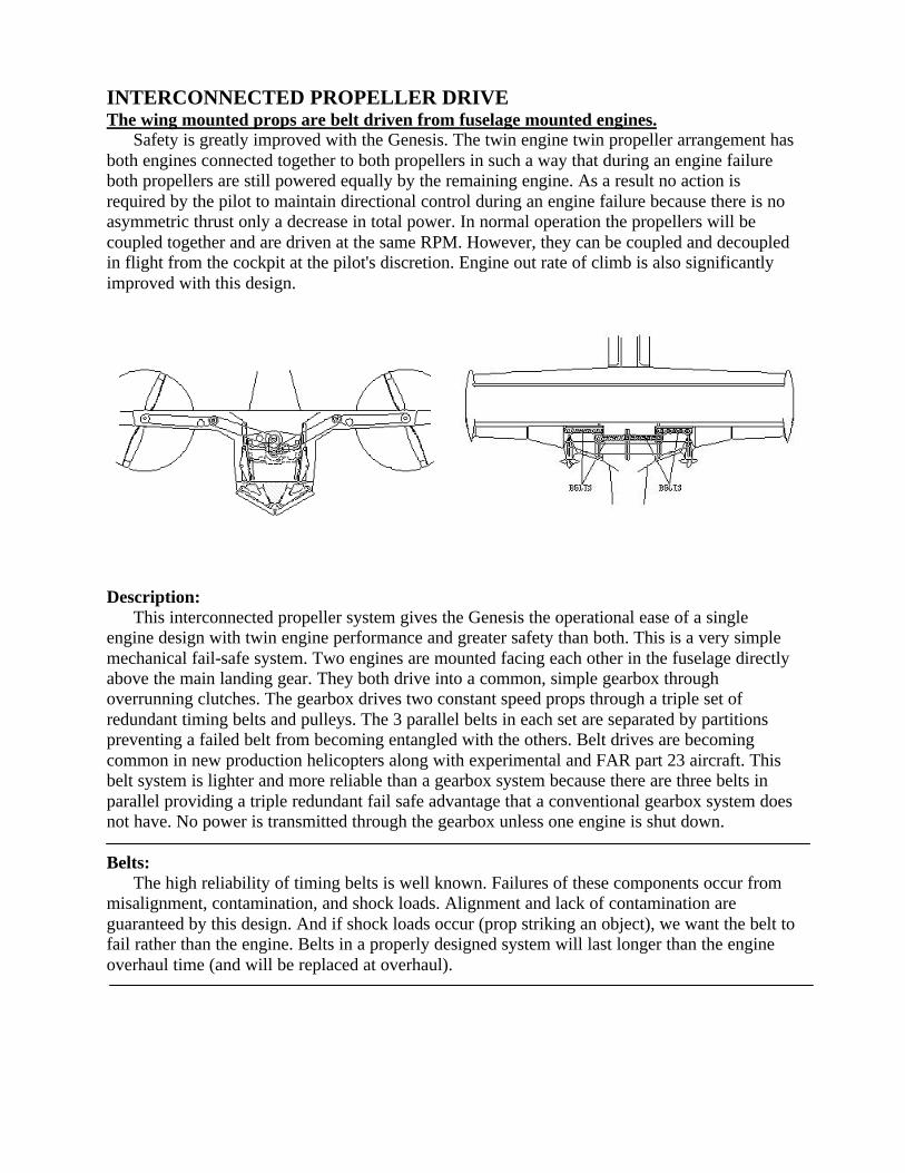
INTERCONNECTED PROPELLER DRIVEThe wing mounted props are belt driven from fuselage mounted engines.
Safety is greatly improved with the Genesis. The twin engine twin propeller arrangement hasboth engines connected together to both propellers in such a way that during an engine failureboth propellers are still powered equally by the remaining engine. As a result no action isrequired by the pilot to maintain directional control during an engine failure because there is noasymmetric thrust only a decrease in total power. In normal operation the propellers will becoupled together and are driven at the same RPM. However, they can be coupled and decoupledin flight from the cockpit at the pilot's discretion. Engine out rate of climb is also significantlyimproved with this design.
Description:This interconnected propeller system gives the Genesis the operational ease of a single
engine design with twin engine performance and greater safety than both. This is a very simplemechanical fail-safe system. Two engines are mounted facing each other in the fuselage directlyabove the main landing gear. They both drive into a common, simple gearbox throughoverrunning clutches. The gearbox drives two constant speed props through a triple set ofredundant timing belts and pulleys. The 3 parallel belts in each set are separated by partitionspreventing a failed belt from becoming entangled with the others. Belt drives are becomingcommon in new production helicopters along with experimental and FAR part 23 aircraft. Thisbelt system is lighter and more reliable than a gearbox system because there are three belts inparallel providing a triple redundant fail safe advantage that a conventional gearbox system doesnot have. No power is transmitted through the gearbox unless one engine is shut down.
Belts:The high reliability of timing belts is well known. Failures of these components occur from
misalignment, contamination, and shock loads. Alignment and lack of contamination areguaranteed by this design. And if shock loads occur (prop striking an object), we want the belt tofail rather than the engine. Belts in a properly designed system will last longer than the engineoverhaul time (and will be replaced at overhaul).
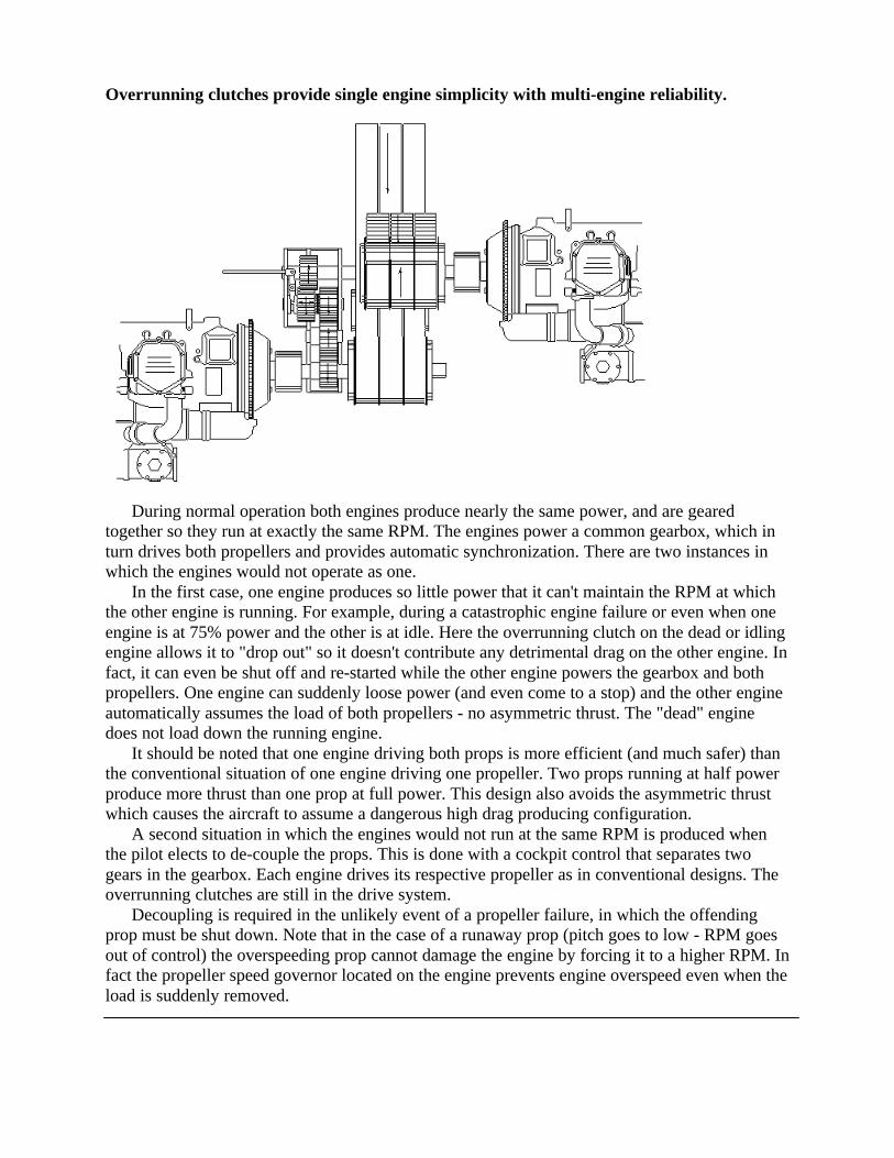
Overrunning clutches provide single engine simplicity with multi-engine reliability.
During normal operation both engines produce nearly the same power, and are gearedtogether so they run at exactly the same RPM. The engines power a common gearbox, which inturn drives both propellers and provides automatic synchronization. There are two instances inwhich the engines would not operate as one.
In the first case, one engine produces so little power that it can't maintain the RPM at whichthe other engine is running. For example, during a catastrophic engine failure or even when oneengine is at 75% power and the other is at idle. Here the overrunning clutch on the dead or idlingengine allows it to "drop out" so it doesn't contribute any detrimental drag on the other engine. Infact, it can even be shut off and re-started while the other engine powers the gearbox and bothpropellers. One engine can suddenly loose power (and even come to a stop) and the other engineautomatically assumes the load of both propellers - no asymmetric thrust. The "dead" enginedoes not load down the running engine.
It should be noted that one engine driving both props is more efficient (and much safer) thanthe conventional situation of one engine driving one propeller. Two props running at half powerproduce more thrust than one prop at full power. This design also avoids the asymmetric thrustwhich causes the aircraft to assume a dangerous high drag producing configuration.
A second situation in which the engines would not run at the same RPM is produced whenthe pilot elects to de-couple the props. This is done with a cockpit control that separates twogears in the gearbox. Each engine drives its respective propeller as in conventional designs. Theoverrunning clutches are still in the drive system.
Decoupling is required in the unlikely event of a propeller failure, in which the offendingprop must be shut down. Note that in the case of a runaway prop (pitch goes to low - RPM goesout of control) the overspeeding prop cannot damage the engine by forcing it to a higher RPM. Infact the propeller speed governor located on the engine prevents engine overspeed even when theload is suddenly removed.
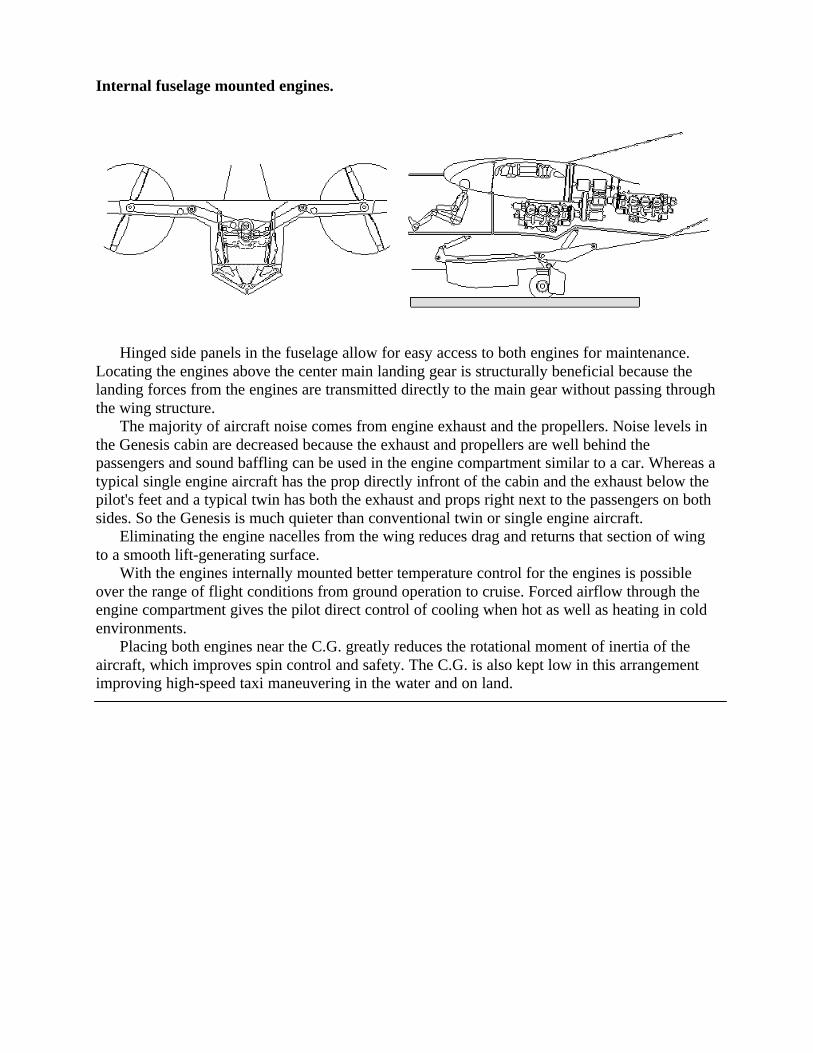
Internal fuselage mounted engines.
Hinged side panels in the fuselage allow for easy access to both engines for maintenance.Locating the engines above the center main landing gear is structurally beneficial because thelanding forces from the engines are transmitted directly to the main gear without passing throughthe wing structure.
The majority of aircraft noise comes from engine exhaust and the propellers. Noise levels inthe Genesis cabin are decreased because the exhaust and propellers are well behind thepassengers and sound baffling can be used in the engine compartment similar to a car. Whereas atypical single engine aircraft has the prop directly infront of the cabin and the exhaust below thepilot's feet and a typical twin has both the exhaust and props right next to the passengers on bothsides. So the Genesis is much quieter than conventional twin or single engine aircraft.
Eliminating the engine nacelles from the wing reduces drag and returns that section of wingto a smooth lift-generating surface.
With the engines internally mounted better temperature control for the engines is possibleover the range of flight conditions from ground operation to cruise. Forced airflow through theengine compartment gives the pilot direct control of cooling when hot as well as heating in coldenvironments.
Placing both engines near the C.G. greatly reduces the rotational moment of inertia of theaircraft, which improves spin control and safety. The C.G. is also kept low in this arrangementimproving high-speed taxi maneuvering in the water and on land.
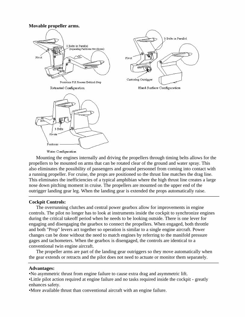
Movable propeller arms.
Mounting the engines internally and driving the propellers through timing belts allows for thepropellers to be mounted on arms that can be rotated clear of the ground and water spray. Thisalso eliminates the possibility of passengers and ground personnel from coming into contact witha running propeller. For cruise, the props are positioned so the thrust line matches the drag line.This eliminates the inefficiencies of a typical amphibian where the high thrust line creates a largenose down pitching moment in cruise. The propellers are mounted on the upper end of theoutrigger landing gear leg. When the landing gear is extended the props automatically raise.
Cockpit Controls:The overrunning clutches and central power gearbox allow for improvements in engine
controls. The pilot no longer has to look at instruments inside the cockpit to synchronize enginesduring the critical takeoff period when he needs to be looking outside. There is one lever forengaging and disengaging the gearbox to connect the propellers. When engaged, both throttleand both "Prop" levers act together so operation is similar to a single engine aircraft. Powerchanges can be done without the need to match engines by referring to the manifold pressuregages and tachometers. When the gearbox is disengaged, the controls are identical to aconventional twin engine aircraft.
The propeller arms are part of the landing gear outriggers so they move automatically whenthe gear extends or retracts and the pilot does not need to actuate or monitor them separately.
Advantages:•No asymmetric thrust from engine failure to cause extra drag and asymmetric lift.•Little pilot action required at engine failure and no tasks required inside the cockpit - greatlyenhances safety.•More available thrust than conventional aircraft with an engine failure.
•An overspeeding propeller will not damage an engine.•Greatly improved engine out rate of climb.•The pilot has a greatly reduced workload during normal takeoff. He is not required to look inthe cockpit for power reductions or to synchronize engines.•Identical engines facing each other allow for counter rotating props which minimizes enginecosts.•Mounting the engines internally also provides better temperature control (cooling & heating).Forced airflow through the engine compartment can be directly controlled by the pilot in flightand on the ground. This is especially advantageous for preflight heating and post flight cooling inboth hot and cold environments.•The location of the propellers and engine exhaust behind the passengers reduces noise levels inthe cabin.•The use of timing belts and the central gear box ensure that both propellers remain at exactly thesame RPM - no pilot action required to synchronize the props which allows more time forscanning of instruments or traffic.•Pulley diameter ratios give speed reduction without using much more expensive geared engines(reduces overhaul cost).•The engines and mounts are protected from propeller imbalance forces, which reduces wear andimproves reliability.•The propellers are protected from engine power pulses, which reduces blade fatigue & improvesreliability of the props.•The engine crankshaft is not stressed from propeller gyroscopic forces.•Forces from a propeller striking an object do not damage the engine crankshaft.•The sudden loss of a prop blade will not try to tear the engine off of the airframe or compromisethe structure.•Hard landings are more tolerable because landing forces due to engine weight are transferred tothe main landing gear directly beneath the engines without passing through the wing structure.•Drag reduction from absence of engine nacelles improves speed and efficiency.•The low center of gravity due to engine location makes high speed taxiing safer on water andland. •Since the engines are not attached to the wing, engine vibrations and landing shocks donot compromise the strength of the wing structure.•Placing both engines near the C.G. greatly reduces the rotational moment of inertia of theaircraft, which improves spin control and safety.•During a takeoff or landing on water, the props are fully shielded from water spray (anddamage) by the wing.•Retracting the landing gear lowers the props to the center of drag eliminating the nose downtrim drag of a high thrust line.•On the ground, passengers and ground personnel are afforded greater safety since the props areabove the wing.•In the unlikely event of a prop failure simply extending the gear puts the prop thrust lines closeto the centerline of the aircraft, minimizing yaw from asymmetric thrust.•In the unlikely event of a prop blade separation, the resulting damage from vibrations will belimited to the prop arm above the wing pivot and not affect the engines, landing gear, or C.G.•With the landing gear retracted, the outriggers fill in the hull aft of the step, forming anaerodynamically clean fuselage.•This patented system allows the C.G. of the engines to remain low while the propellers aremounted in a manner to give protection from water spray and are clear of passengers whileoperating on the ground.
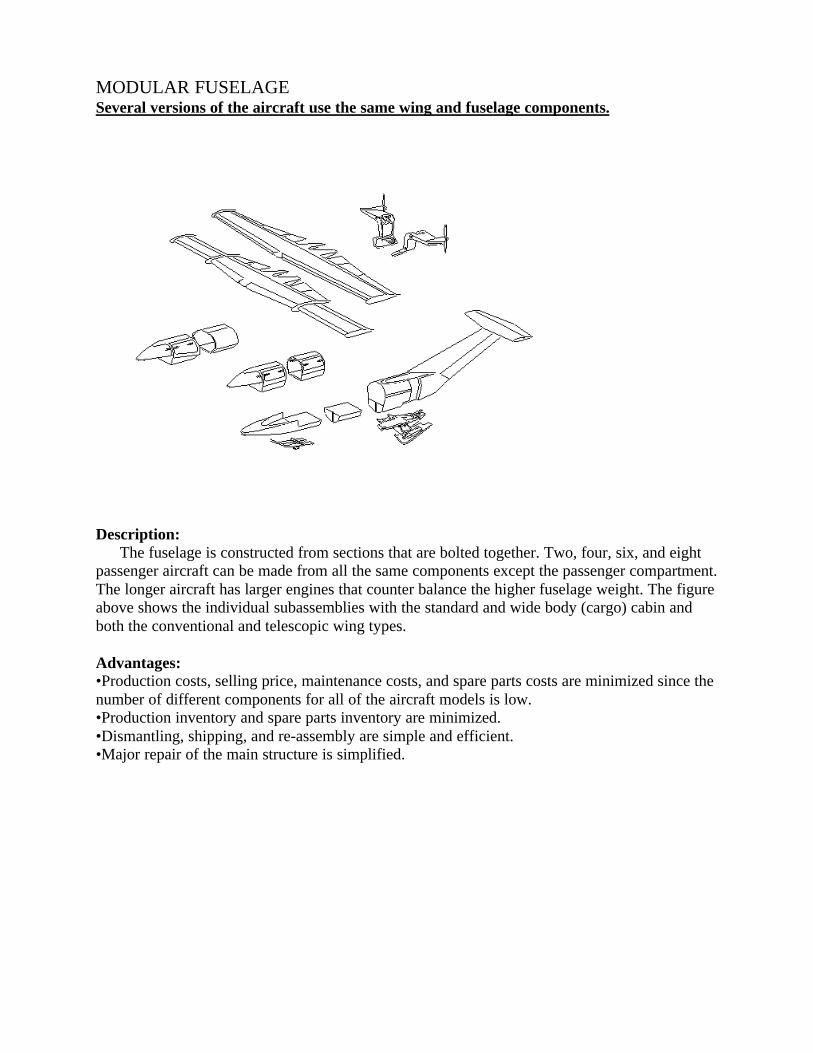
MODULAR FUSELAGESeveral versions of the aircraft use the same wing and fuselage components.
Description:The fuselage is constructed from sections that are bolted together. Two, four, six, and eight
passenger aircraft can be made from all the same components except the passenger compartment.The longer aircraft has larger engines that counter balance the higher fuselage weight. The figureabove shows the individual subassemblies with the standard and wide body (cargo) cabin andboth the conventional and telescopic wing types.
Advantages:•Production costs, selling price, maintenance costs, and spare parts costs are minimized since thenumber of different components for all of the aircraft models is low.•Production inventory and spare parts inventory are minimized.•Dismantling, shipping, and re-assembly are simple and efficient.•Major repair of the main structure is simplified.
SIMPLICITY OF OPERATIONDesigned to be as simple as a single engine airplane to operate.
Control system design innovations in the Genesis aircraft make the pilot duties simple andstraightforward even though the aircraft performs functions never before possible.Wing Extension Control:
The wing extension is simpler than normal flap operation. There is a two position (Extend -Retract) switch that controls the wing position. There are no intermediate positions, although theailerons are fully functional at any point during the wing extension. Fully extended, fullyretracted, and intermediate positions are reported by instrument panel indicator lights. Both theflaps and the wing extensions have the same maximum extend speed limitations. Airspeedsensing limit switches prevent inadvertent extension at high speeds. The appropriate flap andwing extension airspeed range is marked on the airspeed indicator.Landing Gear Position Control:
Although the landing gear has several configurations - dry land, snow, intermittent snow anddry land, water, and retracted, the control is simple. A single multi-position lever is used to selectthe desired configuration. The desired configuration must be selected each time the gear isextended. This eliminates the complexity of having separate selectors for extend/retract andconfiguration.
All configurations can be visually checked by the pilot by looking out the window over hisshoulder. Additionally, there are the conventional position lights. There is no maximum gearextend or retract speed so the gear can be used as speed brakes.Engine and Propeller Controls:
The overrunning clutches and central power gearbox allow for great improvements in enginecontrols. The pilot no longer has to look inside the cockpit to synchronize engines during thecritical takeoff period when he needs to be looking outside.
Power reductions during takeoff are made by first pulling both power levers back to a preset(but adjustable) stop. "Prop" levers are then likewise pulled back together to a stop. These powerreductions can be done without referring to the manifold pressure gages and tachometers.Main Gear Steering Control:
In a conventional aircraft, during crosswind conditions, the pilot has to make a dangerous lastminute cross controlled maneuver immediately before touch down at or near stall speed. In highwinds this maneuver requires considerable pilot skill.
In the same situation the Genesis pilot simply trims the center gear steering at some pointduring the landing approach, then lands in a level and coordinated condition. No cross controlledmaneuvers are ever required. The rudder is used only for taxiing.
The control is a conventional electric trim switch similar to pitch and rudder trim, with amanual trim wheel for backup. There is a position indicator that shows the degree of center geartrim in effect that can be visually compared to the angle of crab of the aircraft during finalapproach.
The trimable center gear can also be used during takeoff. The position returns to center whenthe gear is retracted so it cannot be inadvertently left at the wrong angle for the next landing.Advantages:•Greatly enhanced takeoff safety by not requiring the pilot to synchronize engines or take hisvisual attention from outside the aircraft.•Unparalleled improvement in safety during engine failure, requiring very little pilot attention orability.•Elimination of the need for conventional crosswind landing technique.•Gear position can be verified visually
AERODYNAMICSThe mechanical innovations lead to aerodynamic advantages.Description:Telescopic Wing:
The telescopic wing is an alternative to sophisticated high lift devices (e.g. slotted fowlerflaps). In operation, it is treated like a "span flap" rather a conventional "chord flap". It isused at only low speeds and has a maximum speed limit just as a convention flap.
Swept Tail:The swept tail is a result of connecting the horizontal stabilizer to the back of the fuselage
using the straightest, most direct, structure. This is done rather than extending the fuselagehorizontally and attaching the tail on top of it.
The vertical tail volume (area times moment arm) is generous, although visuallydeceiving. The height of the rudder is typical of "T" tail configurations so that the roll coupleis reasonable.
Inboard Engines:Since the engines are mounted inboard and the propellers are driven by belts, there are no
engine nacelles. The only disturbance to the airflow is the small bump on the trailing edge ofthe wing required to house the belt pulley.
Advantages:•Telescopic Wing
•High lift at low speeds without the drag penalty of flaps.•Increased aspect ratio at low speeds which improves efficiency - unlike conventional flaps.•The retracted configuration has much higher stiffness and resistance to bending and twist(i.e. flutter resistant) than a conventional wing.•The retractable wing is lighter than a conventional wing with the same stall speed, andmaximum speed, and strength requirements
•Swept Tail•The straight line from the fuselage to the tail provides the most rigid structure possible, tocombat high speed flutter.•The tail design is structurally most efficient by attaching directly to the strongest part of theaircraft.•The sweep of the tail provides generous ground clearance for high angle of attack takeoffsand landings.•The lower part of the rudder contributes to yaw control force which lowers the verticalrudder volume (area times moment) minimizing roll resulting from rudder application ("rollcoupling").•The aft swept rudder hinge line provides beneficial pitch up moment from rudderapplication to counteract the usual pitch down tendency.
•Inboard Engines•There are no engine nacelles to detract from maximum lift by disrupting the airflow acrossthe wing.•There are no engine nacelles to create drag.•The airflow through the propellers is not disturbed by large engine nacelles.
DESIGN VERIFICATIONLatest technology analysis and verification.
Stability Verification:The static and dynamic
stability of the design has beenverified using a computersimulation based on an extensivewind tunnel study done by theUnited States Air Force andMcDonnell Douglas Corp. Thisstudy, called the USAF Stabilityand Control Datcom (DATaCOMpendium), is a four volume(3,000 pages) summary of windtunnel tests performed for thepurpose of providing stabilityderivatives and aerodynamicforces for analytical modeling ofaircraft.
Over a period of three years aunique computer program was written which uses the DATCOM results for the sole purpose ofverifying and optimizing the stability of the Genesis design. Other aircraft were modeled as acheck of the accuracy of the program.
This study shows that the Genesis design has desirable characteristics in all measures ofstability and control in both the wings retracted, and extended configurations, and with the gearin all positions. The controllability with an engine inoperative is a particularly significantimprovement over conventional designs. The structurally efficient swept "T" tail shows excellentrudder control down through stall speed - no VMC speed. Rudder induced roll coupling isminimal.
Performance Verification:The performance figures were verified using computer programs based on standard analytical
methods found in widely used design texts. The accuracy of these programs were checked bymodelling common production aircraft and verifying the performance data.
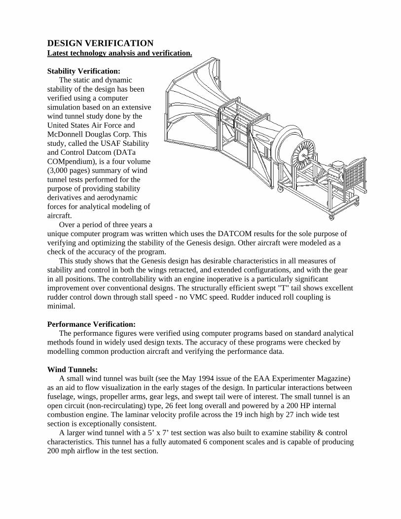
Wind Tunnels:A small wind tunnel was built (see the May 1994 issue of the EAA Experimenter Magazine)
as an aid to flow visualization in the early stages of the design. In particular interactions betweenfuselage, wings, propeller arms, gear legs, and swept tail were of interest. The small tunnel is anopen circuit (non-recirculating) type, 26 feet long overall and powered by a 200 HP internalcombustion engine. The laminar velocity profile across the 19 inch high by 27 inch wide testsection is exceptionally consistent.
A larger wind tunnel with a 5’ x 7’ test section was also built to examine stability & controlcharacteristics. This tunnel has a fully automated 6 component scales and is capable of producing200 mph airflow in the test section.
Finite Element Model:Many aspects of the design are being simulated using a finite element analysis computer
program. This analysis is more sophisticated and complete than was used on the current generalaviation light aircraft at the time they were designed.
Flying Model:A 1/5th scale flying model was built and flown to verify specific aerodynamic considerations
(primarily low speed rudder effectiveness) and to visualize component interactions.
The flying model, wind tunnel tests, and various computer programs are in agreement and arethe basis for the preliminary performance figures.
SPECIFICATIONSUnprecedented safety, utility, and performance.•DIMENSIONS EXTERNAL:
•Wing span extended.............15.24 m (50 ft 0 in)•Wing span retracted...............7.87 m (26 ft 0 in)•Wing chord at fixed root........3.25 m (10 ft 8 in)
•at fixed tip..................…..2.03 m (6 ft 8 in)•at extension root....…...….1.12 m (3 ft 8 in)•at extension tip..........…..1.12 m (3 ft 8 in)
•Wing aspect ratio extended.....8.33•Wing aspect ratio retracted.....3.1•Length overall.......................11.58 m (38 ft 0 in)•Height overall.........................3.75 m (12 ft 4 in)•Tailplane span.........................4.44 m (14 ft 7 in)•Wheel track.............................3.2 m (10 ft 6 in)•Wheelbase...............................6.35 m (18 ft 6 in)•Propeller diameter..................1.98 m (6 ft 6 in)•Passenger door:
•Height.............................0.97 m (3 ft 2 in)•Width..............................2.24 m (7 ft 4 in)
•DIMENSIONS INTERNAL:•Cabin:
•Length.............................3.05 m (10 ft 0 in)•Max width.......................1.21 m (3 ft 11-1/2 in)•Max height......................1.07 m (3 ft 6 in)•Volume...........................3.74 cu.m (132 cuft)
•Nose baggage.....................0.283 cu.m (10 cuft)•Rear baggage......................0.425 cu.m (15 cuft)
•AREAS:•Wing extended, gross...........................28.60 sqm (308 sqft)•Wing retracted, gross...........................20.40 sqm (220 sqft)•Ailerons ret. (total)................................1.16 sqm (12.5 sqft)•Ailerons ext. (total)...............................2.79 sqm (30 sqft)•Trailing edge flaps (tot.)........................0.71 sqm (7.67 sqft)•Vertical stabilizer (not incl. rudder)......4.16 sqm (44.8 sqft)•Rudder, incl. tab.....................................1.39 sqm (15 sqft)•Horizontal stabilizer...............................3.81 sqm (41 sqft)•Elevator incl. tab....................................1.90 sqm (20.5 sqft)
•WEIGHTS:•Empty weight.........................................1540 kg (3600 lb)•Max T O weight.....................................2720 kg (6000 lb)•Max wing loading ext..............................95.1 kg/sqm (19.5 lb/sqft)•Max wing loading ret..............................133. kg/sqm (27.3 lb/sqft)•Max power loading.................................5.61 kg/kW (9.23 lb/hp)
•PERFORMANCE:•Max level speed at max weight of 2720 kg (6000 lb)......... 267 kt (496 km/h; 308 mph)•Cruise speed at max weight of 2720 kg (6000 lb) at S/L, wings retracted
•75% power..................................................................225 kt (450 km/h; 280 mph)•65% power..................................................................214 kt (435 km/h; 270 mph)•one engine inop...........................................................192 kt (386 km/h; 240 mph)
•Stall speed:•flaps, gear, wings retracted...........................................95 kt (175 km/h; 109 mph)•flaps, gear, wings extended...........................................55 kt (101 km/h; 63 mph)
•Rotation speed.....................................................................66 kt (122 km/h; 76 mph)•Approach speed...................................................................71 kt (132 km/h; 82 mph)•T O run:
•on hard surface............................................................220 m (720 ft)•on water.......................................................................305 m (1000 ft)
•T O to 50 ft:•on hard surface............................................................495 m (1625 ft)•on water.......................................................................581 m (1905 ft)
•Landing from 50 ft:•on hard surface............................................................600 m (1970 ft)•on water.......................................................................683 m (2240 ft)
•Landing run:•on hard surface..............................................................70 m (230 ft)•on water.......................................................................152 m (500 ft)
•Range with max fuel (200 gal).......................................1,910 nm(3540 km; 2,200 miles)
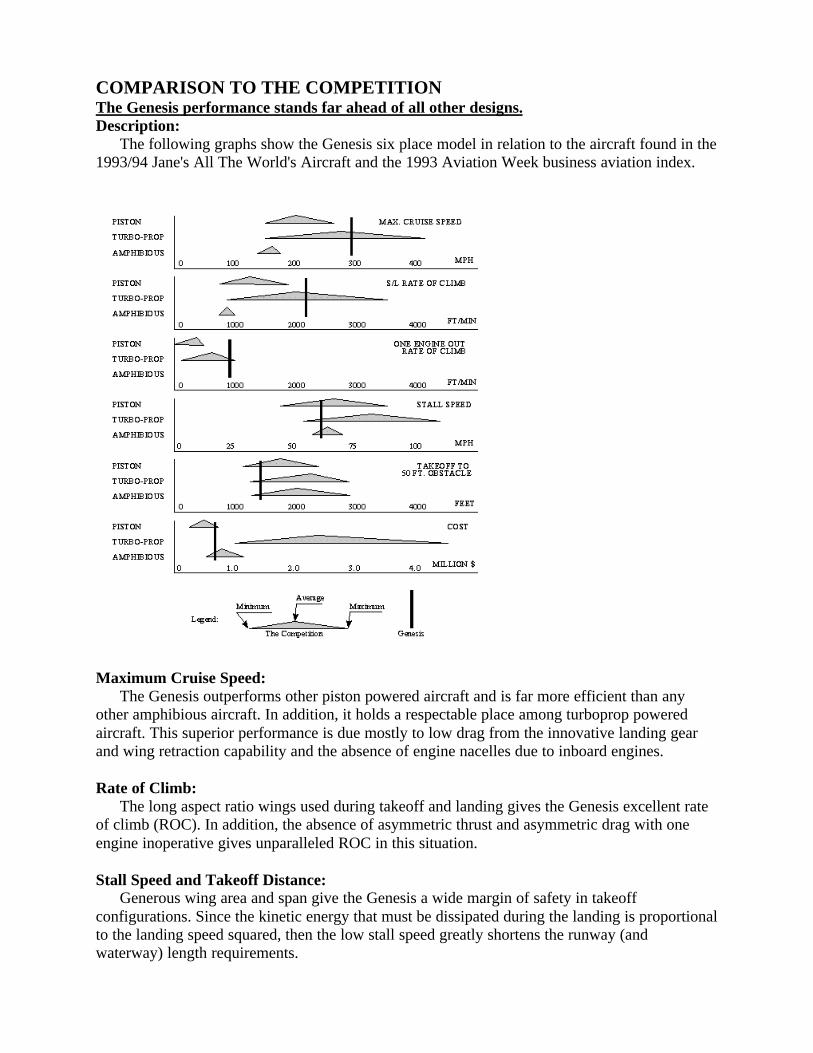
COMPARISON TO THE COMPETITIONThe Genesis performance stands far ahead of all other designs.Description:
The following graphs show the Genesis six place model in relation to the aircraft found in the1993/94 Jane's All The World's Aircraft and the 1993 Aviation Week business aviation index.
Maximum Cruise Speed:The Genesis outperforms other piston powered aircraft and is far more efficient than any
other amphibious aircraft. In addition, it holds a respectable place among turboprop poweredaircraft. This superior performance is due mostly to low drag from the innovative landing gearand wing retraction capability and the absence of engine nacelles due to inboard engines.
Rate of Climb:The long aspect ratio wings used during takeoff and landing gives the Genesis excellent rate
of climb (ROC). In addition, the absence of asymmetric thrust and asymmetric drag with oneengine inoperative gives unparalleled ROC in this situation.
Stall Speed and Takeoff Distance:Generous wing area and span give the Genesis a wide margin of safety in takeoff
configurations. Since the kinetic energy that must be dissipated during the landing is proportionalto the landing speed squared, then the low stall speed greatly shortens the runway (andwaterway) length requirements.
Cost:The projected cost of the Genesis is attractively low. Without the need for turboprop or
geared engines, the major contributor to the selling price (the engines) can be kept low. And inthe case of twin engine aircraft this can save up to half of the cost of the airplane.
The internal mounting of the engines helps raise the strength and lower the cost of this designover the typical amphibious aircraft.
The greatest cost savings come from the modular fuselage design. Different engine sizes andweights offset different fuselage lengths, so all versions of the airplane use nearly all the samecomponents. The manufacturing cost "learning curve" should level off early and at a low level.

SAFETYNumerous innovations make this the safest aircraft ever built.Telescopic Wings:
•The extended wing lowers the stall speed, takeoff distance, landing distance, landing energy,glide angle, and increases the climb rate, climb angle, ceiling, glide distance, range, andendurance.•The retracted wing (in cruise) is much stronger than conventional designs.•Short wing and high wing loading improves tolerance to gust loads and improves ridequality.•In cruise, the outer half of the wing is protected from ice accumulation and is exposed onlyfor landing.
Landing Gear:•Takeoff and landing crosswind limitations are nearly eliminated.•There is no maximum gear extend or retract speed.•The main gear is on the aircraft centerline so that any component failure does not causedirectional control problems.•The pilot can see the gear and determine configuration and condition from his seat.•A gear-up or a water configuration landing on hard surface only effects the reinforced,removable ski panels. Prop tips do not touch the ground.•A water configuration landing on snow does no damage.•A gear-up landing on water or snow does no damage.•A ski-down landing attempt on hard surface or water gives the pilot a warning in time toabort. And if he continues, the damage is minimal.•The landing gear is attached to the engine mounts, so the main landing shock loads do nottransfer through wing spars or fuselage.
Engine and Prop. Mounts, and Drive System:•Both props automatically provide equal thrust in the event of an engine failure.•The pilot has a greatly reduced work load during takeoff. He is not required to look in thecockpit for power reductions.•The rotational inertia is lower than conventional twin engine aircraft.•The engines are easily temperature controlled on the ground and in the air.•The engines are isolated from out of balance forces, gyroscopic forces, and object strikeforces of the props.•The props are isolated from power pulses of the engines.•An overspeeding prop does not overspeed the engine.•Bystanders and passengers are protected from the props during ground operations.•In the event of a prop failure, the prop thrust lines can be brought close together to minimizeasymmetric thrust.•The low CG due to the internal fuselage mounted engines improves the safety of high speedtaxi turns - on land, snow, and water.•More available thrust than conventional aircraft during engine failure.•Little pilot action is required after an engine failure, and no tasks inside the cockpit.
RELIABILITYRedundancy has been designed in so that critical components are minimized.
The most common critical failure modes in light general aviation aircraft have beeneliminated in this design. In some systems, the Genesis has slightly more total components thanthe conventional design, but in all cases the number of critical components has been drasticallyreduced if not totally eliminated. The most common critical components are discussed below:
Landing Gear:•Landing gear components on the Genesis are not considered critical since the main gear ison the centerline of the aircraft. Failure of these components do not cause immediate andviolent loss of directional control as does either of the two main gear on a conventionalaircraft. The outriggers are only for maintaining the aircraft in a level attitude (side to side) attaxi speeds. Failure of either outrigger does not constitute a directional stability hazard.
Drive Train:•Engine components are not considered critical in the Genesis design since the overrunningclutches and gearbox allow the "good" engine to automatically power both propellers.•The clutches are not critical since their failure modes are to either lock in the engagedcondition or to slip, neither of which constitute a directional stability problem.•The gearbox components are not critical since they are not in use during normal operation.No power is transmitted through the gearbox gears unless an engine is shut down.•Engine mounts are not critical in the Genesis design since the engines are in the fuselageand do not support the propellers. The drive pulleys are supported by their own bearings. TheGenesis engine mounts are not likely to fail since prop imbalance does not fatigue the mountsas in conventional designs.•The propeller blades are not critical since a serious imbalance (loss of a blade) wouldseparate the propeller mount arm at a design break point, thereby allowing the damaged propto be thrown free and not take an engine with it.•The drive belts are not critical since there are three belts in parallel between each set ofpulleys. Any drive belt can fail and the other two in the set are capable of handling the load.The three belts in any set are separated by partitions which prevent a failed belt frombecoming entangled with any other belt.•The high reliability of drive belts is well known. Failures of these components occur frommisalignment, contamination, and shock loads. Alignment and lack of contamination areguaranteed by our design. And if shock loads occur (prop striking an object), we want thebelt to fail rather than the engine. Belts in a properly designed system will last longer than theengine overhaul time (and will be replaced at overhaul).
Wings:•The wing extension system is redundantly actuated and has no critical components otherthan the structure itself, which in cruise, is much stronger than conventional designs . Theextension/retraction mechanism is a simple system of cables. Redundancy is built in so thatfailure of any cable does not hinder safe operation.•The extension ailerons are always actuated in unison with the fixed wing ailerons, whetherextended, retracted, or in transition. The actuation is also a simple cable system. The aircraftcan be taken off and landed with the wings extended, retracted, or partially extended.

THE MARKETThe high utility nature of the Genesis allows for a broad market.
The Gevers Genesis will be the only aircraft ever produced in which a single plane can fulfillthe requirements of all of the following categories simultaneously without modification. Inaddition, it will perform exceptionally well in each. For this aircraft, unlike the competition,gaining versatility in one area does not limit its performance in the other areas. In fact, the designfeatures which give the Genesis its versatility also increase its performance above thecompetition's.
Bush planeShort take offs and landings to unimproved runways on sod, water, and snow covered areas.
Obviously requires STOL performance, but also requires ruggedness with maintenance materialsand techniques which can be performed in the "bush". In addition, long range and high cruisespeeds are desirable to travel great distances into undeveloped areas and return quickly withoutthe need to refuel.
SeaplaneAmphibious with good water handling abilities. Stable in the water for recreational activities
such as fishing. Highly economical to operate for recreational purposes. Also not restricted towater bases, able to commute between water, dry land, and snow covered airstrips withoutmodification to the landing gear.
Personal / PleasureRecreational flying, travel to distances too far to drive, and sight seeing. Requires an aircraft
which is simple and economical to operate and is perceived safe. Ability to personalize theaircraft in unique ways such as tail art. High resale value due to versatility and durability.
Executive / BusinessShort and long trips taken at unscheduled times by company pilots generally to areas not
serviced by the airlines. Requires comfortable aircraft with high cruise speed.
Flight TrainingFor beginners, many short training flights, sometimes handled roughly. Requires durable,
simple to operate, stable, easily maintained aircraft with good visibility for collision avoidance,and low landing speeds.
For advanced training, single or multi-engine operation, retractable gear, high performance,instrument cross country training, and is safe in the most adverse training conditions (e.g. oneengine inoperative and cross wind takeoffs and landings). Amphibious & ski landing gear allowfor seaplane & snow landing training.
Search and RescueHigh speed cruise to the site then maximized loiter time until return or Short Take Off and
Landing (STOL) performance to drop off supplies or return with passengers. Requires highcruise performance with short take off and landing capabilities. Also requires fuel efficient loitermode with good downward visibility. The ability to land in a variety of terrain (water, land, &snow) is highly beneficial.
Air CargoTransport of bagged and/or palletized material. Requires maximum cabin volume and
durable floor and walls. The aircraft should have a comfortable performance safety margin atgross weight. Long range and efficiency are also desirable. Occasionally carrying cargo toremote areas with a variety of terrain for landing.
AerobaticRequires a high degree of maneuverability, strength capable of achieving high 'g' loads, and
high speeds.
Aerial PhotographyHigh speed cruise to the site then mild maneuvers and high speed cruise return. Requires
good downward visibility from cabin, good performance, stable flight when pilot is distracted,and high wing loading for smooth camera platform.
FREQUENTLY ASKED QUESTIONSWe welcome and encourage responses, (comments and questions), concerning the
information presented here. Contact Gevers Aircraft by e-mail at <[email protected]>Or write to:
Gevers Aircraft, Inc.PO Box 430Brownsburg, Indiana 46112 USA
Some of the most commonly asked questions are:
Q: What is the reliability of the belts in the propeller drive?A: Belts of this type have been used for many years in machinery having much harsherenvironments, (i.e. higher loads, dirtier surroundings, little or no maintenance, etc.), and havebeen proven to be very effective and reliable. In addition, this is a redundant system consisting of3 sets of belts in each segment, any 2 of which can carry the maximum power required.
Q: Can the aircraft be landed safely with the wings retracted?A: Yes. Not only can the aircraft be safely landed in the fully retracted wing configuration, but itis intended to be taken off and landed in the wings retracted configuration in flight training tosimulate high performance aircraft. Think of the extended wing as nothing more than span-wiseflaps as opposed to conventional chord-wise flaps. Normal landings are intended to be conductedwith wings extended, however, as with other aircraft, safe landings can be performed with flapsretracted. With the wings retracted stall speed is just over 100 MPH, the retracted configurationlanding will be typical of a conventional high performance twin. In addition, the aircraft canmaneuver and land safely with the wings in any position including transition between extendedand retracted.
Q: Is there enough aileron power to handle a failed prop in "short-wing" configuration?A: The short wing has a large aileron-to-wing area ratio, and therefore, sufficient aileron control.Although there is sufficient aileron control in the short wing configuration it would beappropriate to detail the further aerodynamic benefits resulting from our design elements in theevent of a prop failure.* Simply lowering the landing gear brings the prop centerlines close to the center of the aircraft.* Counter-rotating props reduces asymmetric thrust.* With the gear/prop arm retracted the props are nearly centered on the wing trailing edge. Theangle of attack of the prop remains nearly constant, therefore the thrust line does not shift towardthe down going blade (P-factor) because the wing forces the airflow through the prop at aconstant angle.
Q: Does the aft engine & forward passenger design pose a C.G. problem?A: No. The passenger loading is typical of conventional aft-engine designs. The center of gravityenvelope will accommodate occupancy by either a single pilot or the full compliment ofpassengers and baggage.
Q: How do you accommodate the very high propeller shaft bending moments due to changes inangle of attack and sideslip, created by the large gyroscopic forces in maneuvers?A: The prop arm is designed as a rigid box structure. It is relatively short (spanwise) and deep(chordwise) and is quite strong in torsion due to the triangular cross-section (taken in a plane
parallel to the wing ribs). The arms are stronger than typical engine mounts on aerobatic aircraft,which have to resist not only gyroscopic forces but also landing impact loads of the engines.
Q: The pictures don't show a step in the hull bottom for water operations.A: The aircraft does have a conventional step for water operation even though the pictures do notshow its details. With the gear retracted, the outriggers are stowed in the recess in the aft bottomof the fuselage behind the step filling it in to provide an aerodynamically clean hull in cruise.When the outriggers are extended, that recess becomes the ventilated area behind the step. Thestep is the heel of the main center gear skis when they are retracted and as such provide a shockabsorbing nature to the step. Note that in the water configuration the outriggers are fullyextended while the main center gear and skis remain retracted.
Q: Doesn't the thick vertical fin produce extra drag?A: The significant strength and stiffness improvement of this tail boom design allows for aweight reduction over conventional tail booms which more than compensates for the few poundsof added drag which have been calculated.
Q: Does the propeller drive system require specialized pilot training?A: No. In fact, pilot training will be easier in the Genesis. All seaplanes have the propellersmounted high to keep them clear of the water spray. When increasing from idle to full power theconventional high engine mounting produces a change in pitching moment that is greater andmore sudden than that for the Genesis when moving the propellers from low to high positions.So no more pilot training is needed than for any other amphibian. We should have less pitchchange than a typical amphibious aircraft since the prop wash downloads the "T" tail. The pitchdown tendency due to a high thrust line is offset by the added down wash across the horizontaltail. One of the most difficult and dangerous situations for a twin engine pilot is when one enginefails on takeoff. In this situation the Genesis' interconnected engines vastly reduces the workloadon the pilot in the emergency situation. Props are only de-coupled for taxi operation.
Q: Is a computer controlled system required to provide gain/trim changes for stability and controlin each configuration?A: No.The Landing gear drag is approximately balanced above and below the wing - thus little pitchchange.The wing pitching moments are approximately balanced (inboard vs. outboard wing) - thus littlepitch change.The prop wash downloads the tail - thus approximately balancing nose down thrust with taildown inverse lift.
CONCLUSIONOnly innovation can revitalize General Aviation.
Mission Statement:Gevers Aircraft, Inc. is committed to rejuvenating General Aviation through a new series of
aircraft which are ingeniously innovative in design, and boldly aggressive in performance andutility goals. All aspects of these designs will provide the most inherently safe aircraft ever built.
Design Goals:•Safety - Eliminate the current major contributors to aircraft accidents.•User Friendly - Simple to operate.•Modular - 2 place to 8 place with mostly interchangeable assemblies.•Utility -Hard surface, water, and snow take off and landing capability.•Performance - Competitive with conventional light twins.•Cost - Affordable for the customer and profitable for the manufacturer.•Maintenance - Easy, cheap, and "low tech." repairability and maintenance.•Certification - Manufacturing processes to be stable, accurate, traceable, easily monitored, andcontinuously evaluated.
Design Philosophy:The design was undertaken with the attitude that, initially, all goals were to be completely
met., regardless of the cost and complexity. After a design took shape, the various capabilitieswere to be evaluated against the disadvantages. The worth while aspects were to be kept and lessworthy aspects were to be discarded for the final version.
Design Synergy:What emerged from the design, guided by the above philosophy, was a surprise. All of these,
apparently conflicting goals were accomplished through an incredible synergy that existsbetween various aspects of the aircraft. This design is the result of a lengthy refinement of thatsynergy. The various systems and components of the aircraft, not only work smoothly together,but actually enhance each other. Furthermore, this synergy extends past the operation of theaircraft into the manufacturing, maintenance, and repair of the aircraft. We have thus reacheddesign goals never before attempted with surprisingly few compromises.
The Future:Gevers Aircraft Inc. will build a proof-of-concept aircraft, followed by a refined prototype.
The ultimate goal is for production certification under Federal Aviation Regulation Part 23. Theschedule for the plan is dependant upon the level of investor participation.
"IF WE ARE TO ACHIEVE RESULTS NEVER BEFORE ACCOMPLISHED... WEMUST EXPECT TO EMPLOY METHODS NEVER BEFORE ATTEMPTED." -FRANCIS BACON -