g/gh - gpm
TRANSCRIPT
G/GHMultistage high pressure pumps

G
2
33
MULTISTAGE CENTRIFUGAL PUMPS
APPLICATIONSG series multistage centrifugal pumps are designed for trou-ble-free pumping for clear or slightly dirty liquids and used in:
Heating plants •Waterworks and water supply plants •Pressure raising plants •Water and condensate circulation •Fire fighting system •Boiler feeding plants •High pressure washing •Reverse osmosis•
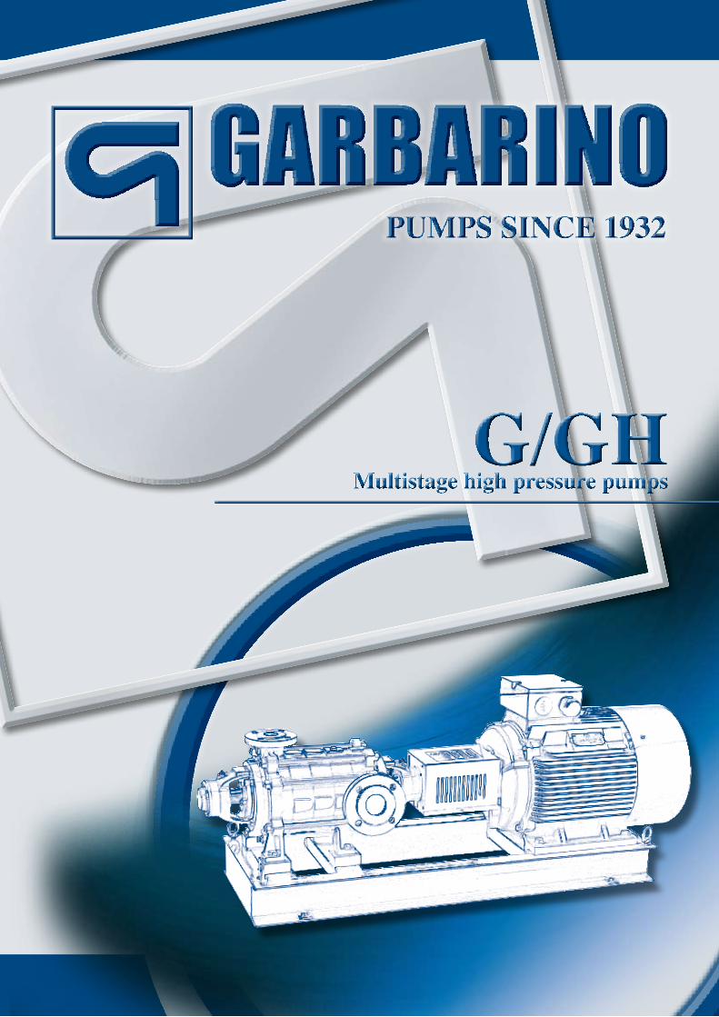
CONSTRUCTION The pumps are multistaged centrifugal with radial split casings. In all versions the supporting feet on pressure side are placed under the discharge body. For sizes up to 3’’ the base feet, on suction side, are placed under the first stage casing, to allow the rotation of the suction casing in any direction. For bigger sizes the base feet are placed under the suction body, the ro-tation of which is possible only upon request. The impellers are provided with balancing holes to reduce the axial thrust. The shaft is supported by grease or oil lubricated bearings.
MAXIMUM OPERATING TEMPERATURE Standard version: up to 248°FWith cooling chamber: up to 320 °FNOTE: for temperatures exceeding 320°F please contact our Technical Department.
MAXIMUM OPERATING PRESSUREOn suction side: up to 362 PSI•On discharge side: up to 928 PSI•NOTE: for higher operating pressures, please contact our •Technical Department
TECHNICAL FEATURESCapacity up to 3150 GPM•Heads to 1312 feet•Revolutions up to 3600 RPM•Pressures to 928 PSI•Flanges: suction side: ANSI B16.1 CL125, ANSI B16.5 •CL150discharge side: ANSI B16.1 CL 250, ANSI B16.5 CL 300, •ANSI B16.5 CL 400 (option)
VERTICAL MULTISTAGE CENTRIFUGAL PUMPS“GV” SERIESVertical multistage centrifugal pumps “GV” series, standard configuration, with upper ball bearings support and lower bushing support. Besides the usual applications where high pressure is required, the vertical configuration is largely used in the marine field. For sizes not shown in tables please con-tact our Technical Department.
2

bare shaft version (G)
section of closed impeller
vertical version (GV)
oil lubricated version (125 G)
MATERIALS MAX. wORkING PRESSURE
CAST IRON 580 PSI
STAINLESS STEEL, BRONzE, SPECIAL ALLOy 925 PSI
note: special executions exceeding the above limits available on request
MOdELS 10
INTERCHANGEABILITy
CASINGS 10
IMPELLERS 12
SHAFTS 10
BEARING BRACkETS 6
MECHANICAL SEALS 6
2
332

GHMAXIMUM OPERATING TEMPERATUREStandard version: up to 248°FWith cooling chamber: up to 320 °FNOTE: for temperatures exceeding 320°F please contact our Technical Department.
TECHNICAL FEATURESMaximum capacity 2200 GPM•Maximum head 1100 PSI•Maximum speed 3600 RPM, lowest critical speed over •5000 RPM Single or double mechanical seal (balanced type)•Optional seal cooling•
GH pumps can be supplied in a range of materials to offer custom compatibility with pumped liquid, another appealing feature of the pumps. The base version has a nodular cast iron body (GS 600) and G25 cast iron impellers, but special stainless steel pumps are available, such as AISI 316, Du-plex, Superduplex, Hastelloy B and C, Monel, Alloy 20 and others.
MULTISTAGE HIGH PRESSURECENTRIFUGAL PUMPS Garbarino’s multistage pump family has been widely tested over the years in applications with pressures up to 580 PSI. Now, with the newly developed GH pumps, we can achieve pressures to 1100 PSI and capacities to 2200 GPM.
APPLICATIONSThese pumps are suitable for applications mainly in po-wer and desalination plants, for boiler feeding and reverse osmosis respectively. Moreover they can be used in other fields such as snowmaking equipment, marine and off-shore industries for water mist fire fighting services and others.
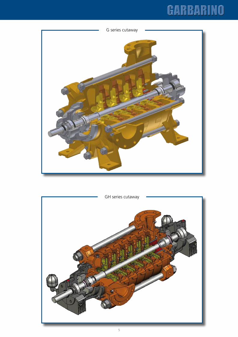
CONSTRUCTIONThe GH design is the newest in the industry, we have used an entirely new approach to hydraulics and mechanics for high pressure pumps. The range of GH pumps includes 4 sizes (2, 3, 4 and 6 inch) with 8 different hydraulic systems to insure that every client demand can be met. The pumps are multi-stage, horizontal pumps radially split with impellers assembled between external bearings. The main features are:
feet cast with suction unit and delivery for greater rigidity •and strength ANSI flanges are standard with all metric options available •suction flange rotating to three positions •high efficiency enclosed type impellers with low NPSH •suction impeller replaceable wear rings •oil-sealed external bearings with constant level olier •drum-type balancing device for axial thrust •oversized shaft to reduce deflection.•
55
4
4
G series cutaway
GH series cutaway
554

76
G SERIES GREASE LUBRICATEd PARTS CROSS-SECTION
GH SERIES PARTS CROSS-SECTION
6586.12510
6542.13851
6510.11510
32002110
6571 30166700.4
6577.22460.2
6474
11306542.2
220014101150 1521
1413 6586.2
2410
1660 4200
6510.1 1140 4610.3 68553012
6577.2 6576.24213
2450.26580 6700.1 6700.2
32634300.12460.1
32002450.16577.14610.1
4300.14300.26576.16700.3 3261
4610.2
6576.1
42004610.24610.86586.1
2510 6510.44610.4
3200 6571 21106510.165806855
22101510 1150
6700.11521 1660
6577.34210 4610.54610.7
42136700.4
4300.1 6542.26586.26700.3
32663856
6510.34300.16542.13854 3012
4610.62460.1 2450.1 4610.1
14106579.1 1130 2200
6700.2 626211401413
6210 6474.16230
6220 6576.2 3016 38556577.26576.1 2460.24610.10
6577.14300.2
6700.5 4260 2450.24610.9
6510.2
6474.22531 6579.2
2450.3 4610.3
24913270

7
VERTICAL VERSION (GV)
Pos description
1130 Suction casing
1140 Discharge casing
1150 Stage casing
1410 Diffuser
1413 Diffuser, last stage
1510 Casing wear ring
1521 Wear ring
1660 Delivery casing bush
2110 Pump shaft
2200 Impeller
2210 Impeller suction stage
2410 Interstage sleeve
2450.1 Shaft sleeve
2450.2 Shaft sleeve
2450.3 Shaft sleeve
2460.1 Spacer sleeve
2460.2 Spacer sleeve
2491 Locating bearing collar
2510 Spacer ring
2531 Retaining ring
3012 Roller bearing
3016 Ball bearing
3160
4300.2
2460.1
4200
1660
6571
6700.1
6700.3
2110
3016
3851
6510.1
6474
1140
1410
1150
6594
3311
6700.2
4213
6576.2
6577.2
1521
1130
6855
6576.5
6576.3
3266
3170
4610.4
6580
2450.1
1510
4610.2
2200 2410
6700.4
6577.1
1413
2450.2
4610.4
6576.1
6576.4
3200
4610.1
4300.1
6542.1
6586.1
3261
Pos description
3160 Motor stool
3170 Pump stool
3200 Bearing housing
3261 Bearing cover
3263 Bearing cover
3266 Bearing end cover
3270 Oil lubrication cover
3311 Bearing bush
3851 Grease cup
3854 Oil filler plug
3855 Constant level oiler
3856 Oil level
4200 Mechanical seal
4210 Seal housing
4213 Mechanical seal cover
4260 Spring
4300.1 Radial shaft seal
4300.2 Radial shaft seal
4610.1 O-ring
4610.2 O-ring
4610.3 O-ring
4610.4 O-ring
4610.5 O-ring
4610.6 O-ring
4610.7 O-ring
4610.8 O-ring
4610.9 O-ring
4610.10 O-ring
6210 Balance drum
6220 Static ring
6230 Rotating ring
6262 Balance piping
6474._ Cylindrical setting pin
6510.1 Screw plug
6510.2 Screw plug
6510.3 Screw plug
6510.4 Screw plug
6542.1 Lockwasher
6542.2 Lockwasher
6571 Housing tie bolt
6576._ Screw
6577._ Screw
6579._ Screw
6580 Nut
6586.1 Locknut
6586.2 Locknut
6594 Set screw
6700._ key
6855 Plain washer

PERFORMANCES (G)
HEA
D
1750 RPM
CAPACITY Q m3/h
H feet
H mt
GPM
5678
10
20
30
40
50
100
200
300
400
2 3 4 5 10 20 30 40 50 100 200 300 700
20
30
40
50
100
200
300
400
500
1000
500
1500
7
10 11
12
8
9
6
5
4
3
2
1314
7
10
12
8
9
6
5
4
3
14
11
13
2
7
10
8
9
3
2
5
4
6
3
2
5
4
6
11
1213
7
8 9
1011
3
2
4
5
6
7
89
10
3
2
4
5
6
7
8
9
3
4
5
6
7
2
3
4
5
6
7
2
8
3
4
5
6
7
2
8
3
4
5
6
7
2
3
4
5
6
23
4
5
2
6
8
10 20 30 40 50 100 200 300 400 500 1000 2000 3000
25G
32G 40G
50G 65G80G
100G125Gr
125Gn150G
200Gr
200Gn
3500 RPMPERFORMANCES (G)
HEA
D
CAPACITY Q m3/h
GPM
H feetH mt
20 30 40 50 100 200 300 400 500 1000
70
8090100
200
300
400
500
1000
2
3
4
5
6
7
8
9
10
111213
2
4
5
6
7
8
9
10
3
2
4
5
6
7
8
3
2
4
5
6
7
3
2
4
5
6
3
2
4
5
3 2
3
1300
1500
20
30
40
50
100
200
300
400
4 5 10 20 30 40 50 100 200
150
300
500
25G
32G 40G 50G
65G
80G
100G
8

1750 RPM
2
3
4
5
6
7
8
9
10
100050030015050 1500400200100
100
200
300
400
500
600
800900
150
50
250
350
450
700
14
56
28
42
70
84
112
140
280
210
3612 24 36012048 60 72 96 2407.2 9.6
3
4
5
6
7
8
9
10
1112
13
1514
2
2
3
4
5
6
7
8
9
1011
12
13
1415
2
3
4
5
6
7
8
910
2
3
5
6
7
8
4
2
3
4
5
6
7
8
2
3
4
5
2
3
4
5
50A50B
65A
65B
100A100B
150A150B
PERFORMANCES (GH)
HEA
D
H mt H feet
CAPACITY Q m3/h
GPM
3500 RPM
50A 50B
65A65B
100A100B
150A150B
2
3
4
5
6
7
8
9
10
11
1213
15
2
3
4
5
6
7
8
9
10111213
1415
2
3
4
5
6
7
8
910
2
3
4
5
6
7
8
910
2
3
5
6
7
8
2
3
4 4
5
6
7
8
2
3
4
5
2
3
4
5
14
PERFORMANCES (GH)
HEA
D
36
1120
56
42
70
84
112
140
12 24
420
280
700
560
840
36012048 60 72 96 240 600480 720
1400
7.2 9.6
CAPACITY Q m3/h
2000100050030015050 25001500400200100 3000
200
300
400
500
600
8009001000
1500
2000
2500
3000
150
250
350
450
700
35004000
4500
H mt
H feet
GPM
9

SUCTION FLANGEPUMP SHAFT
SECTIONDISCHARGE FLANGE
t
d1
u
b'
n2n1
m3
g2
b Øs
m2 v c
d1
g g'
DN
s
K D
DN
d
K'
D'
D2D2
D1
PM2
PM1
g1f
a
h1h2
m1
lbb'
vm1
m3m2
g2
d1
g1f
PM1PM2
D2D2
l
SUCTION FLANGEPUMP SHAFT
SECTIONDISCHARGE FLANGE
t
d1
u
b'
n2n1
m3
g2
b Øs
m2 v c
d1
g g'
DN
s
K D
DN
d
K'
D'
D2D2
D1
PM2
PM1
g1f
a
h1h2
m1
lbb'
vm1
m3m2
g2
d1
g1f
PM1PM2
D2D2
l
PUMP TYPENUMBER
OF STAGES25 G 32 G 40 G 50 G 65 G 80 G 100 G 125 G 150 G 200 G
f m1 m2 f m1 m2 f m1 m2 f m1 m2 f m1 m2 f m1 m2 f m1 m2 f m1 m2 f m1 m2 f m1 m22 4.37 5.59 3.86 4.80 5.59 3.86 5.43 5.71 3.98 6.18 6.02 4.29 6.77 7.52 5.55 6.77 11.89 9.92 8.70 15.00 12.64 10.75 20.59 16.65 12.99 24.80 20.47 16.54 29.13 24.023 6.61 7.83 6.10 7.05 7.83 6.10 7.87 8.15 6.42 8.74 8.58 6.85 9.92 10.67 8.70 9.92 15.04 13.07 12.44 18.74 16.38 15.79 25.63 21.69 18.50 30.31 25.98 23.23 35.43 30.314 8.86 10.08 8.35 9.29 10.08 8.35 10.31 10.59 8.86 11.30 11.14 9.41 13.07 13.82 11.85 13.07 18.19 16.22 16.18 22.48 20.12 20.83 30.67 26.73 24.02 35.83 31.50 29.92 41.73 36.615 11.10 12.32 10.59 11.54 12.32 10.59 12.76 13.03 11.30 13.86 13.70 11.97 16.22 16.97 15.00 16.22 21.34 19.37 19.92 26.22 23.86 25.87 35.71 31.77 29.53 41.34 37.01 36.61 48.03 42.916 13.35 14.57 12.83 13.78 14.57 12.83 15.20 15.47 13.74 16.42 16.26 14.53 19.37 20.12 18.15 19.37 24.49 22.52 23.66 30.75 28.39 30.91 40.75 36.81 35.04 46.85 42.52 43.31 54.33 49.217 15.59 16.81 15.08 16.02 16.81 15.08 17.64 17.91 16.18 18.98 18.82 17.09 22.52 23.27 21.30 22.52 27.64 25.67 27.40 33.70 31.34 35.94 45.79 41.85 40.55 52.36 48.038 17.83 19.06 17.32 18.27 19.06 17.32 20.08 20.35 18.62 21.54 21.38 19.65 25.67 26.42 24.45 25.67 30.79 28.82 31.14 37.44 35.08 40.98 50.83 46.899 20.08 21.30 19.57 20.51 21.30 19.57 22.52 22.80 21.06 24.09 23.94 22.20 28.82 29.57 27.60 28.82 33.94 31.97
10 22.32 23.54 21.81 22.76 23.54 21.81 24.96 25.24 23.50 26.65 26.50 24.76 31.97 32.72 30.7511 24.57 25.79 24.06 25.00 25.79 24.06 27.40 27.68 25.94 29.21 29.06 27.3212 26.81 28.03 26.30 27.24 28.03 26.30 29.84 30.12 28.3913 29.06 30.28 28.54 29.49 30.28 28.54 32.28 32.56 30.8314 31.30 32.52 30.79 31.73 32.52 30.7915 33.54 34.37 32.64
kEy ACCORDING TO uNI 6604
pump type 25 G ÷ 65 G pump type 80 G ÷ 200 G
SUCTION FLANGE POSITION
DRIVE END VIEW STANDARD ON REquEST
OVERALL dIMENSIONS (G)
1111
PUMP DIMENSIONS(inches )
wEIGhT(lbs)
PUMP TyPE
SUcT
ION
FlAN
GE
DElIv
ERy
FlAN
GE
FlANGES DRIllED AccORDING TO
ANSI B16.1 - B16.5
BEAR
ING
BRAc
kET
DRAI
NcA
SING
PUM
P DR
AIN
vAcU
UM G
AUGE
PRES
SURE
GAU
GE
a g1 h1 h2 g2 b c m3 n1 n2 s v d1 l t u2 stagespump
+1stage
DNs150
DNd300
D D’ b b’ K K1 g g’n° holesn° fori D2 D1 PM1 PM2
DNs DNd6.30 10.79 5.20 6.30 8.19 1.77 0.55 2.17 9.84 8.46 0.59 12.60 1.10 2.36 1.22 0.31 154 26 25 G 1 1/2'' 1 1/4'' 6.14 5.5 0.81 0.75 3.88 3.88 0.62 0.75 4 4 3/8’’G 1/4’’G 1/4’’G 1/4’’G7.09 10.55 6.30 7.09 8.11 1.77 0.55 2.17 11.02 9.65 0.59 12.80 1.10 2.36 1.22 0.31 187 35 32 G 2'' 1 1/4'' 6.5 5.5 0.71 0.75 4.75 3.88 0.75 0.75 4 4 3/8’’G 1/4’’G 1/4’’G 1/4’’G7.09 11.46 6.30 7.09 8.39 1.77 0.55 2.17 11.02 9.65 0.59 14.21 1.26 3.15 1.39 0.39 220 40 40 G 2 1/2'' 1 1/2'' 7.28 5.9 0.71 0.8 5.5 4.5 0.75 0.88 4 4 3/8’’G 1/4’’G 1/4’’G 1/4’’G7.87 11.69 6.30 7.87 8.62 1.77 0.55 2.17 11.02 9.65 0.59 14.88 1.26 3.15 1.39 0.39 276 49 50 G 3'' 2'' 7.87 6.5 0.79 0.71 6 5 0.75 0.75 4 8 3/8’’G 1/4’’G 1/4’’G 1/4’’G9.45 12.20 7.09 9.45 8.90 2.36 0.63 2.56 12.6011.02 0.59 14.96 1.26 3.15 1.39 0.39 342 64 65 G 4'' 2 1/2'' 9 7.28 0.94 0.71 7.5 5.88 0.75 0.88 8 8 3/8’’G 1/4’’G 1/4’’G 1/4’’G9.45 12.20 7.09 9.45 8.90 2.36 0.63 2.56 12.6011.02 0.59 10.63 1.26 3.15 1.39 0.39 287 66 80 G 4'' 3'' 9 7.87 0.94 0.79 7.5 6.62 0.75 0.88 8 8 3/8’’G 1/4’’G 1/4’’G 1/4’’G12.0114.21 8.46 12.01 9.96 3.15 0.87 3.15 16.7313.78 0.87 12.24 1.57 4.33 1.70 0.47 441 99 100 G 5'' 4'' 10 9.25 0.94 0.94 8.5 7.88 0.88 0.88 8 8 3/8’’G 3/8’’G 3/8’’G 3/8’’G15.7516.5412.4015.7512.76 4.13 0.98 4.92 22.0517.91 0.98 13.58 1.77 4.33 1.92 0.55 1,135 231 125 G 6'' 5'' 11.22 11 1 0.94 9.5 9.25 0.88 0.88 8 8 3/8’’G 1/2’’G 1/2’’G 1/2’’G17.7219.2914.7617.7215.24 5.51 1.18 5.91 27.5622.05 1.30 15.55 1.97 4.33 2.14 0.63 1,764 342 150 G 8'' 6'' 13.5 12.5 1.13 1 11.7510.62 0.88 0.88 8 12 3/8’’G 3/8’’G 3/8’’G 3/8’’G19.6922.8316.3419.6917.09 5.91 1.38 6.50 29.5324.41 1.54 18.90 2.36 5.51 2.54 0.71 220 441 200 G 10'' 8'' 15.9816.33 1.26 1.13 14.25 13 1 1 12 12 3/8’’G 3/8’’G 3/8’’G 3/8’’G
10

SUCTION FLANGEPUMP SHAFT
SECTIONDISCHARGE FLANGE
t
d1
u
b'
n2n1
m3
g2
b Øs
m2 v c
d1
g g'
DN
s
K D
DN
d
K'
D'
D2D2
D1
PM2
PM1
g1f
a
h1h2
m1
lbb'
vm1
m3m2
g2
d1
g1f
PM1PM2
D2D2
l
m2m1
f
t
d
u
l
DN
s
h1
Mandata: PN64 - PN100Aspirazione: PN 16Flange:
m1 n2
n1
ea h2
h2
DN d
c
m2 s
PM2
PM1
D1
OVERALL dIMENSIONS (GH)
PUMP dIMENSIONS
PUMP TyPE g3 p r e i t q
25 GV 10.63 6.54 13.78 11.81 0.16 0.71 0.94
32 GV 10.55 6.30 13.78 11.81 0.16 0.71 0.94
40 GV 11.61 6.81 15.75 13.78 0.16 0.71 0.94
50 GV 11.85 7.05 15.75 13.78 0.16 0.71 0.94
65 GV 12.13 7.56 19.69 16.93 0.16 0.71 0.94
80 GV 12.13 7.56 15.75 13.78 0.16 0.71 0.94
100 GV 14.37 8.27 19.69 16.93 0.31 0.71 1.18
125 GV 17.28 9.45 21.65x21.65 17.72x17.72 0.16 0.71 3.35
200 GV 23.23 12.60 27.56x27.56 23.62x23.62 0.16 0.87 3.15+0.39r
e
pg3
f h1
q
n. iøt
h2
OVERALL dIMENSIONS (GV)
SUCTION AND DELIVERY FLANGES VIEW
DN s dDN
STANDARD ON REQUESTON REQUESTSTANDARD
1111
SuCTION FLANGE:ANSI B16.1 CL125, ANSI B16.5 CL150DISCHARGE FLANGE:ANSI B16.1 CL 250, ANSI B16.5 CL 300ANSI B16.5 CL 600 (option)
PUMPTYPE dNs dNd N°
STAGES a e f h1 h2 c m1 m2 n1 n2 s d1 l t u d1 PM1 PM2 wEIGHT (lbs)
50 3.15 1.97
2 5.91
11.85 14.80 6.30 8.46 0.98 3.15 1.57 13.98 12.40 0.87 ø 1.50 3.15 1.61 0.39 1/2” 3/8” 3/8”
2433 8.46 2734 11.02 3045 13.58 3356 16.14 3667 18.70 3978 21.26 4289 23.82 45910 26.38 48911 28.94 52012 31.50 55113 34.06 58214 36.61 61315 39.17 64416 41.73 67517 44.29 705
65 3.94 2.56
2 7.09
12.48 15.94 7.09 9.84 1.18 3.54 1.77 17.72 14.17 0.94 ø 1.65 4.33 1.77 0.47 1/2” 3/8” 3/8”
3753 10.04 4194 12.99 4635 15.94 5076 18.90 5517 21.85 5958 24.80 6399 27.76 68310 30.71 72811 33.66 77212 36.61 816
100 5.91 3.94
2 9.13
14.06 17.91 8.86 11.81 1.18 4.72 2.36 19.69 16.54 0.94 ø 1.89 4.33 20.28 0.55 3/4” 1/2” 1/2”
4303 12.76 5004 16.38 5715 20.00 6426 23.62 7127 27.24 7838 30.87 8539 34.49 924
150 7.87 5.91
2 12.01
15.87 20.83 10.63 14.96 1.38 5.91 2.95 23.62 19.29 1.10 ø 2.36 5.51 2.52 0.71 3/4” 1/2” 1/2”
5953 16.54 7104 21.06 8255 25.59 9396 30.12 1,054

ww
w.li
zea.
com
www.pompegarbarino.com
POMPE GARBARINO S.p.A.
Headquarters:Via Marenco, 44 - 15011 Acqui Terme (AL) - Italy - Tel. +39 0144.388671 - Fax +39 0144.55260
E-mail: [email protected]
Milan Branch:Viale Andrea Doria, 31 - 20124 Milano - Italy - Tel. +39 02.67070037 - Fax +39 02.67070097
E-mail: [email protected]
Distributed in North America by:
Global Pump MarketingNorth American Sales Headquarters
2810 Hampton Glen Ct. - Matthews, NC 28105Phone: 704-845-0847 - Fax: 704-844-0137 - E-mail: [email protected]
Global Pump MarketingDistribution Center
6256 N. Telegraph Rd. - Dearborn Heights, MI 48127Phone: 313-278-7867 - Fax: 313-278-6812 - E-mail: [email protected]
ATEX on request