ggu transient man e
TRANSCRIPT
7/29/2019 Ggu Transient Man e
http://slidepdf.com/reader/full/ggu-transient-man-e 1/42
Modelling of transient groundwater flow
GGU-TRANSIENT
VERSION 6
Last revision: May 2012
Copyright: Prof. Dr. Johann Buß
Technical implementation and sales: Civilserve GmbH, Steinfeld
7/29/2019 Ggu Transient Man e
http://slidepdf.com/reader/full/ggu-transient-man-e 2/42
Contents:
1 Preface .......................................................... ................................................................ ........ 5
2 Licence protection and installation ...................................................... .............................. 6
3 Language selection....... ............................................................... ......................................... 6
4 Program concept............................................................... ................................................... 7
5 Starting the program........................................................ ................................................... 8
6 Short description.......................................... ................................................................ ........ 9
7 Description of menu items........................... ............................................................... ....... 10
7.1 File menu.................................................. ............................................................... ....... 10
7.1.1 "Load GW data" menu item............................................................................ ....... 10
7.1.2 "Save as" menu item........................................................ ...................................... 10
7.1.3 "System info" menu item........................................................... ............................ 10
7.1.4 "Load boundary values" menu item............................................ ........................... 10
7.1.5 "Save boundary values" menu item ...................................................... ................. 10 7.1.6 "Printer preferences" menu item........................................................... ................. 10
7.1.7 "Print and export" menu item ............................................................... ................. 11
7.1.8 "Exit" menu item................................................................................... ................. 12
7.1.9 "1, 2, 3, 4" menu items............................................................... ............................ 12
7.2 Time BC menu .............................................................. ................................................. 13
7.2.1 General notes on time-dependent boundary conditions...................... ................... 13
7.2.2 "Preferences" menu item............................................................ ............................ 13
7.2.3 "Soil properties" menu item....................... ............................................................ 13
7.2.4 "Edit polygon courses" menu item........................................................ ................. 15
7.2.5 "Delete all" menu item..................... ............................................................... ....... 16 7.2.6 "Point potential or source" menu item............................................................. ...... 16
7.2.7 "(Potential or source) In section" menu item......................................................... 17
7.2.8 "Linear (potential or source)" menu item ........................................................ ...... 17
7.2.9 "Linear sources" menu item....................... ............................................................ 17
7.2.10 "Diffuse sources" menu item ................................................................ ................. 18
7.2.11 "Diffuse sources for soils" menu item ............................................................. ...... 18
7.2.12 "Check" menu item.......................................................... ...................................... 18
7.2.13 "Display all polygon courses" menu item............................................. ................. 18
7.2.14 "Special 1" menu item (for vertical-plane or axis-symmetrical systems only) ...... 19
7.2.15 "Special 2" menu item (for vertical-plane or axis-symmetrical systems only) ...... 19 7.2.16 "Special 3" menu item (for vertical-plane or axis-symmetrical systems only) ...... 20
7.2.17 "Blanket layer water level in section" menu item (for leaky aquifer only)............ 21
7.2.18 "Linear (blanket layer water level)" menu item (for leaky aquifer only)...............21
7.2.19 "Show (blanket layer water level)" menu item (for leaky aquifer only)........ ........ 21
7.3 Fixed BC menu ............................................................. ................................................. 22
7.3.1 General notes on "fixed" boundary conditions ...................................................... 22
7.3.2 "Preferences" menu item............................................................ ............................ 22
7.3.3 "Check" menu item.......................................................... ...................................... 22
GGU-TRANSIENT User Manual Page 2 of 42 May 2012
7/29/2019 Ggu Transient Man e
http://slidepdf.com/reader/full/ggu-transient-man-e 3/42
7.3.4 "Point potential or source" menu item ................................................................... 22
7.3.5 "In section" menu item.......................................................................... ................. 22
7.3.6 "Linear sources" menu item....................... ............................................................ 22
7.3.7 "Diffuse sources" menu item ................................................................ ................. 23
7.3.8 "Diffuse sources for soils" menu item ............................................................. ...... 23
7.3.9 "Blanket layer water level" menu item (for leaky aquifer only)............................ 23 7.4 Check menu.............................................. ............................................................... ....... 24
7.4.1 General note............... ................................................................ ............................ 24
7.4.2 "Preferences" menu item............................................................ ............................ 24
7.4.3 "Mesh" menu item .......................................................... ....................................... 24
7.4.4 "Outline" menu item ........................................................ ...................................... 24
7.4.5 "Outline (coloured)" menu item............................................................................. 24
7.4.6 "Contours" menu item........................................................................... ................. 24
7.4.7 "Contours (coloured)" menu item.................................................................... ...... 25
7.5 Modelling menu ............................................................ ................................................. 26
7.5.1 "Start" menu item.................................................. ................................................. 26 7.6 Graphics preferences menu...................................................... ...................................... 28
7.6.1 "Refresh and zoom" menu item ............................................................ ................. 28
7.6.2 "Zoom info" menu item ............................................................. ............................ 28
7.6.3 "Pen colour and width" menu item....................................................... ................. 28
7.6.4 "Legend font selection" menu item........................................................................ 28
7.6.5 "Mini-CAD toolbar" and "Header toolbar" menu items........................................ 29
7.6.6 "Toolbar preferences" menu item ......................................................... ................. 29
7.6.7 "General legend" menu item................................................................. ................. 30
7.6.8 "Soil properties legend" menu item ...................................................... ................. 31
7.6.9 "kr = f(u) function legend" menu item................................................................... 32 7.6.10 "nw = f(u) function legend" menu item........................................................... ...... 33
7.6.11 "k = f(t) function legend" menu item............................................................... ...... 34
7.6.12 "Move objects" menu item.................................................................... ................. 34
7.6.13 "Save graphics preferences" menu item................................................................. 35
7.6.14 "Load graphics preferences" menu item.......................................................... ...... 35
7.7 Page size + margins menu.................................................................. ............................ 35
7.7.1 "Auto-resize" menu item....................................................................... ................. 35
7.7.2 "Manual resize (mouse)" menu item................................................................ ...... 35
7.7.3 "Manual resize (editor)" menu item....................................................................... 35
7.7.4 "Font size selection" menu item............................................................................. 36 7.7.5 "Page size and margins" menu item....................................................................... 36
7.8 ? menu...................................................... ............................................................... ....... 37
7.8.1 "Copyright" menu item.............................................................. ............................ 37
7.8.2 "Maxima" menu item...................................................... ....................................... 37
7.8.3 "Help" menu item ............................................................ ...................................... 37
7.8.4 "GGU on the web" menu item......... ............................................................... ....... 37
7.8.5 "GGU support" menu item.............................................................................. ....... 37
7.8.6 "What's new?" menu item................ ................................................................ ...... 37
7.8.7 "Language preferences" menu item...................................................... ................. 37
GGU-TRANSIENT User Manual Page 3 of 42 May 2012
7/29/2019 Ggu Transient Man e
http://slidepdf.com/reader/full/ggu-transient-man-e 4/42
8 Tips and tricks......................................................... ........................................................... 38
8.1 Keyboard and mouse..................... ................................................................ ................. 38
8.2 Function keys ...................................................... ........................................................... 39
8.3 "Copy/print area" icon.............................. ............................................................... ....... 40
9 Index................................................................................... ................................................. 41
GGU-TRANSIENT User Manual Page 4 of 42 May 2012
7/29/2019 Ggu Transient Man e
http://slidepdf.com/reader/full/ggu-transient-man-e 5/42
1 Preface
The GGU-TRANSIENT program allows modelling of transient groundwater flow in horizontal-
plane, vertical-plane and axis-symmetrical groundwater systems using the finite element method.
Data input is in accordance with conventional WINDOWS operations and can therefore be learned almost entirely without the use of a manual. In order to avoid unnecessarily inflating the program,
no evaluation routines have been included in GGU-TRANSIENT. For evaluation and presenta-
tion of transient groundwater flow, please see the GGU-PLGW program. Using GGU-PLGW
you can, for instance, generate a coloured animation, reflecting the flow development in specified
time intervals. Furthermore, GGU-PLGW allows presentation of the various flow quantities along
sections through the modelled system, as well as the temporal changes in these values (hydro-
graphs) at specified points in the system.
It is not the aim of this manual to offer an introduction to the finite-element method. For details of
the finite-element method, please see O. C. Zienkiewicz, " Methode der Finiten Elemente" ("Finite-
Element Methods"), Carl Hanser Verlag Munich Vienna, 1984. The hydraulic basics used in the
FEM program can be taken from, e.g., J. Buß "Unterströmung von Deichen" (Announcement 92,Leichtweiß-Institut, TU Braunschweig).
The program system has been used in a large number of projects and has been thoroughly tested
(using analytical solutions and in comparison with other FEM applications). No faults have been
found. Nevertheless, liability for completeness and correctness of the program and the manual,
and for any damage resulting from incompleteness or incorrectness, cannot be accepted.
The following general notes are important:
The data basis is represented by steady-state systems imported from the
GGU-SS-FLOW2D program.
Triangular elements are used.
Darcy's Law applies.
The piezometric heads are calculated in a linear manner for each element.
GGU-TRANSIENT User Manual Page 5 of 42 May 2012
7/29/2019 Ggu Transient Man e
http://slidepdf.com/reader/full/ggu-transient-man-e 6/42
2 Licence protection and installation
In order to guarantee a high degree of quality, a hardware-based copy protection system is used
for the GGU-TRANSIENT program.
The GGU software protected by the CodeMeter copy protection system is only available inconjunction with the CodeMeter stick copy protection component (hardware for connection to the
PC, "CM stick"). Because of the way the system is configured, the protected software can only be
operated with the corresponding CM stick. This creates a fixed link between the software licence
and the CM stick copy protection hardware; the licence as such is thus represented by the CM
stick. The correct Runtime Kit for the CodeMeter stick must be installed on your PC.
Upon start-up and during running, the GGU-TRANSIENT program checks that a CM stick is
connected. If it has been removed, the program can no longer be executed.
For installation of GGU software and the CodeMeter software please refer to the information in
the Installation notes for GGU Software International , which are supplied with the program.
3 Language selection
GGU-TRANSIENT is a bilingual program. The program always starts with the language setting
applicable when it was last ended.
The language preferences can be changed at any time in the "?" menu, using the menu item
"Spracheinstellung" (for German) or "Language preferences" (for English).
GGU-TRANSIENT User Manual Page 6 of 42 May 2012
7/29/2019 Ggu Transient Man e
http://slidepdf.com/reader/full/ggu-transient-man-e 7/42
4 Program concept
An initial steady-state condition is required for time-dependent modelling of groundwater flow.
GGU-TRANSIENT acquires this initial condition from a record (e.g. "Gwh1.da1" or
"Gwv1.da1") generated during a previous analysis using the GGU-SS FLOW2D application. It is
therefore necessary to load this file first after opening the program. Beside the results, this file alsocontains the soil properties upon which the steady-state modelling is based. These steady-state soil
properties (k, neff , etc.) cannot be altered from within the GGU-TRANSIENT program. If amend-
ment of these values were allowed, the soil properties would no longer correlate to the calculated
potentials and discharges and the transient modelling would produce nonsensical results. How-
ever, additional soil properties, which are required for transient modelling, must be provided as a
function of the type of groundwater system (vertical-plane, horizontal-plane, etc.).
Further to these additional soil properties, time-dependent boundary conditions can also be
defined with GGU-TRANSIENT. You must define boundary values (potential or discharge) as a
function of time, by means of polygon courses. These polygon courses can then be assigned sys-
tem nodes, either individually or in groups. Soil properties (transient) and polygon courses, as well
as their allocations to system nodes, can be saved in a separate file as so-called boundary data, in
order to make them available again for later modelling.
Boundary conditions defined in the course of steady-state modelling (GGU-SS-FLOW2D) are
also contained in the file (e.g. "Gwh1.da1"). They are assumed by the program to be constant for
the whole modelling duration, unless the so-called fixed boundary conditions are deleted in GGU-
TRANSIENT.
The GGU-TRANSIENT program allows presentation of the steady-state file results (e.g.
"Gwh1.da1") on the screen, facilitating quick and easy control. Transient data cannot be evaluated
using the GGU-TRANSIENT program. The GGU-PLGW program is available for this purpose;
it is described in a separate user manual.
Generally, when modelling transient groundwater systems, a flood of result values is generated.
Modelling results are saved by the GGU-TRANSIENT program in a file "_t.plw". The file con-
taining the base data (polygon courses, etc.) has the name "_ t.dat ". When modelling is complete,
this file is automatically saved and then automatically reloaded when the GGU-SS-FLOW2D file
(".da1") is reloaded.
The GGU-TRANSIENT program is started using conventional WINDOWS operations. The
program is equipped with a large number of error queries. Nonsensical input will usually be
caught by the program and an error message displayed on the screen. Independently of this you
should, for security reasons, intermittently save longer input.
GGU-TRANSIENT User Manual Page 7 of 42 May 2012
7/29/2019 Ggu Transient Man e
http://slidepdf.com/reader/full/ggu-transient-man-e 8/42
5 Starting the program
After starting the program, you will see two menus at the top of the window:
File
?
After clicking on the "File" menu, a system processed with the GGU-SS-FLOW2D program can
be loaded by means of the "Load GW data" menu item.
The processed system record is saved in GGU-SS FLOW2D using the ".da1" extension, in
order to make it available for GGU-TRANSIENT. The program function to be activated
for this purpose can be found in GGU-SS-FLOW2D in the "System/Analyse" menu item.
Then, the menu bar will show eight menus:
File
Time BC
Fixed BC
Check
Modelling
Graphics preferences
Page size + margins
?
After clicking one of these menus, the so-called menu items roll down, allowing access to all
program functions.
The program works on the principle of What you see is what you get. This means that the screen
presentation represents, overall, what you will see on your printer. In the last consequence, this
would mean that the screen presentation would have to be refreshed after every alteration you
make. For reasons of efficiency and as this can take several seconds for complex screen contents,
the GGU-TRANSIENT screen is not refreshed after every alteration.
If you would like to refresh the screen contents, press either [F2] or [Esc]. The [Esc] key addi-
tionally sets the screen presentation back to your current zoom, which has the default value 1.0.
GGU-TRANSIENT User Manual Page 8 of 42 May 2012
7/29/2019 Ggu Transient Man e
http://slidepdf.com/reader/full/ggu-transient-man-e 9/42
6 Short description
Since I know from personal experience that reading user-manuals is quite a chore, there will now
follow a short description of the main program functions. After studying this section you will be in
a position to model transient groundwater flow. You can learn about the details of the program in
the later chapters.
In order to be able to use the system entered in your GGU-SS-FLOW2D groundwater
flow program for transient modelling using the GGU-TRANSIENT program, you must
create a file in the GGU-SS-FLOW2D program with the file extension ".da1". You can
create this file by going to "System/Analyse" and activating the check box "Generate re-
cord for transient modelling".
Start the GGU-TRANSIENT program and, using the menu item "File/Load GW data",
select the system from which you would like to analyse transient groundwater flow.
Then, using the "File/Load boundary values" menu item, either load boundary values
defined in a previous sitting into the system or specify new boundary conditions using the
menu "Time BC" or "Fixed BC".
Using the "Time BC/Soil properties" menu item, you can query the soil properties which
you defined in GGU-SS-FLOW2D. This list is supplemented by information on the
specific storage coefficient. In the case of a vertical-plane system, you can define your
specific soil curves, using modelling points and according to soil type, by clicking on the
"nw = f(u)" field (cf . Figure 1 in Section 7.2.3).
Using the menu item "Time BC/Edit polygon courses" you specify the temporal change
in, e.g., a potential boundary condition. This is initially independent of location. By
clicking on the menu item you will see a dialog box within which, by clicking on the
"New" button and then "Change polygon course", you can specify the number of polygon
points, i.e. the number of temporal changes in your potentials.
Assign system nodes a boundary condition polygon using "Time BC/Point potential or
source".
With the help of the "Modelling/Start" menu item the program analyse the transient
groundwater flow with the user-defined boundary conditions. You can specify the final
time and the temporal increment in the dialog box.
Use the GGU-PLGW program for evaluation and visualisation of the modelling results; it
also provides a means of printing an impressive graphic of the results. To do this, load the
file generated by GGU-TRANSIENT ("_t.plw") into GGU-PLGW. An initial evaluation
can also be carried out parallel to modelling.
GGU-TRANSIENT User Manual Page 9 of 42 May 2012
7/29/2019 Ggu Transient Man e
http://slidepdf.com/reader/full/ggu-transient-man-e 10/42
7 Description of menu items
7.1 File menu
7.1.1 "Load GW data" menu item
Existing steady-state groundwater modelling data generated with the GGU-SS-FLOW2D pro-
gram can be loaded into GGU-TRANSIENT. This file has the default name of ".da1". In order to
enable generation of this record by the GGU-SS-FLOW2D program, you must activate the "Gen-
erate record for transient modelling" check box in the "System/Analyse" menu item. If you are
not sure which system is in the ".da1" file, go to the "Check" menu.
7.1.2 "Save as" menu item
For parameter studies - e.g. when adopting various polygon courses - it is advisable to generate
individual ".da1" initial records, because you cannot influence the naming of your transient analy-
sis result files. The program stores the base data automatically in a ".dat" file under the name of
the initial file and extended by a "_t". The results required for subsequent evaluation in GGU-
PLGW are automatically saved in a "_t.plw" file. It is therefore possible that different transient
systems are mistakenly exported to the same result files if the same initial record is used.
Using this menu item the data are saved in an existing or a new file with the file extension ".da1".
If you do not enter an extension when saving ".da1" will be used automatically.
7.1.3 "System info" menu item
Upon opening this menu item you will be presented with information on the currently loaded
system, the number of triangular elements and on the nodes.
7.1.4 "Load boundary values" menu item
Using this menu item you can reload a ".dat" file containing boundary values which was previ-
ously defined and saved with the "File/Save boundary values" menu item, in order to further
process this or to use it as the basis for transient modelling. The file contains the transient soil
properties and the polygon courses, as well as the allocations of the polygon courses to the system
nodes.
7.1.5 "Save boundary values" menu item
After selecting this function you can save the defined boundary values in order to have the dataavailable again at a later date. The file contains the transient soil properties and the polygon
courses, as well as the allocations of the polygon courses to the system nodes.
7.1.6 "Printer preferences" menu item
You can edit printer preferences (e.g. swap between portrait and landscape) or change the printer
in accordance with WINDOWS conventions.
GGU-TRANSIENT User Manual Page 10 of 42 May 2012
7/29/2019 Ggu Transient Man e
http://slidepdf.com/reader/full/ggu-transient-man-e 11/42
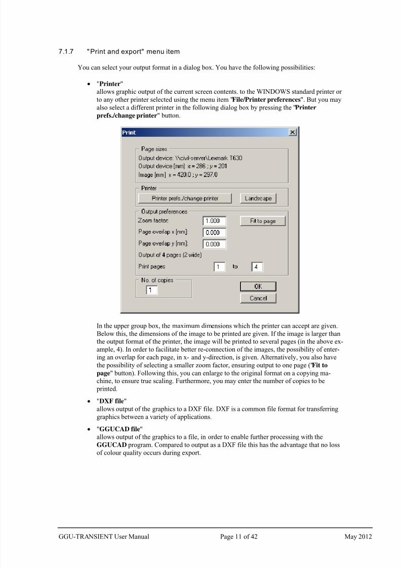
7.1.7 "Print and export" menu item
You can select your output format in a dialog box. You have the following possibilities:
"Printer"
allows graphic output of the current screen contents. to the WINDOWS standard printer or
to any other printer selected using the menu item "File/Printer preferences". But you mayalso select a different printer in the following dialog box by pressing the "Printer
prefs./change printer" button.
In the upper group box, the maximum dimensions which the printer can accept are given.
Below this, the dimensions of the image to be printed are given. If the image is larger than
the output format of the printer, the image will be printed to several pages (in the above ex-
ample, 4). In order to facilitate better re-connection of the images, the possibility of enter-
ing an overlap for each page, in x- and y-direction, is given. Alternatively, you also have
the possibility of selecting a smaller zoom factor, ensuring output to one page ("Fit to
page" button). Following this, you can enlarge to the original format on a copying ma-
chine, to ensure true scaling. Furthermore, you may enter the number of copies to be
printed.
"DXF file"
allows output of the graphics to a DXF file. DXF is a common file format for transferring
graphics between a variety of applications.
"GGUCAD file"
allows output of the graphics to a file, in order to enable further processing with the
GGUCAD program. Compared to output as a DXF file this has the advantage that no loss
of colour quality occurs during export.
GGU-TRANSIENT User Manual Page 11 of 42 May 2012
7/29/2019 Ggu Transient Man e
http://slidepdf.com/reader/full/ggu-transient-man-e 12/42
"Clipboard"
The graphics are copied to the WINDOWS clipboard. From there, they can be imported
into other WINDOWS programs for further processing, e.g. into a word processor. In order
to import into any other WINDOWS program you must generally use the " Edit/Paste"
function of the respective application.
"Metafile"
allows output of the graphics to a file in order to be further processed with third party soft-
ware. Output is in the standardised EMF format (Enhanced Metafile format). Use of the
Metafile format guarantees the best possible quality when transferring graphics.
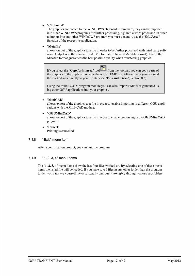
If you select the "Copy/print area" tool from the toolbar, you can copy parts of
the graphics to the clipboard or save them to an EMF file. Alternatively you can send
the marked area directly to your printer (see "Tips and tricks", Section 8.3).
Using the "Mini-CAD" program module you can also import EMF files generated us-
ing other GGU applications into your graphics.
"MiniCAD"
allows export of the graphics to a file in order to enable importing to different GGU appli-
cations with the Mini-CAD module.
"GGUMiniCAD"
allows export of the graphics to a file in order to enable processing in the GGUMiniCAD
program.
"Cancel"
Printing is cancelled.
7.1.8 "Exit" menu item
After a confirmation prompt, you can quit the program.
7.1.9 "1, 2, 3, 4" menu items
The "1, 2, 3, 4" menu items show the last four files worked on. By selecting one of these menu
items the listed file will be loaded. If you have saved files in any other folder than the program
folder, you can save yourself the occasionally onerous rummaging through various sub-folders.
GGU-TRANSIENT User Manual Page 12 of 42 May 2012
7/29/2019 Ggu Transient Man e
http://slidepdf.com/reader/full/ggu-transient-man-e 13/42
7.2 Time BC menu
7.2.1 General notes on time-dependent boundary conditions
Using this menu item you can define the time-dependent boundary conditions for the system and
specify soil properties if this has not already been carried out in GGU-SS-FLOW2D.
7.2.2 "Preferences" menu item
This menu item allows the font sizes for node and polygon course labelling to be edited. In addi-
tion, you may specify whether the user-defined polygon courses are to be labelled and define the
formatting.
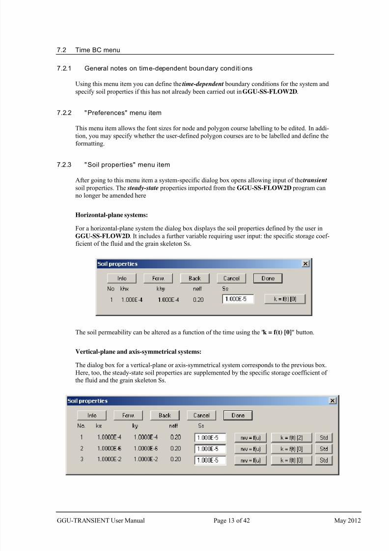
7.2.3 "Soil properties" menu item
After going to this menu item a system-specific dialog box opens allowing input of the transient
soil properties. The steady-state properties imported from the GGU-SS-FLOW2D program can
no longer be amended here
Horizontal-plane systems:
For a horizontal-plane system the dialog box displays the soil properties defined by the user in
GGU-SS-FLOW2D. It includes a further variable requiring user input: the specific storage coef-
ficient of the fluid and the grain skeleton Ss.
The soil permeability can be altered as a function of the time using the "k = f(t) [0]" button.
Vertical-plane and axis-symmetrical systems:
The dialog box for a vertical-plane or axis-symmetrical system corresponds to the previous box.
Here, too, the steady-state soil properties are supplemented by the specific storage coefficient of
the fluid and the grain skeleton Ss.
GGU-TRANSIENT User Manual Page 13 of 42 May 2012
7/29/2019 Ggu Transient Man e
http://slidepdf.com/reader/full/ggu-transient-man-e 14/42
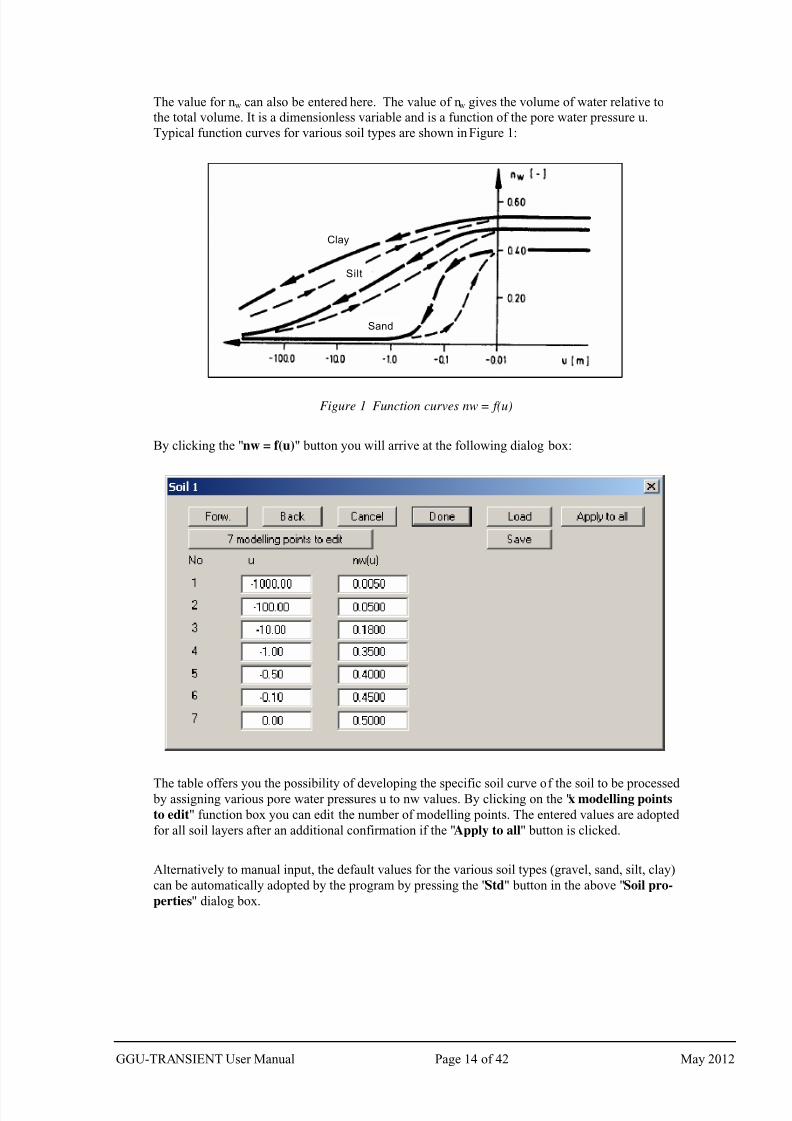
The value for nw can also be entered here. The value of nw gives the volume of water relative to
the total volume. It is a dimensionless variable and is a function of the pore water pressure u.
Typical function curves for various soil types are shown in Figure 1:
Figure 1 Function curves nw = f(u)
By clicking the "nw = f(u)" button you will arrive at the following dialog box:
The table offers you the possibility of developing the specific soil curve of the soil to be processed by assigning various pore water pressures u to nw values. By clicking on the "x modelling points
to edit" function box you can edit the number of modelling points. The entered values are adopted
for all soil layers after an additional confirmation if the "Apply to all" button is clicked.
Alternatively to manual input, the default values for the various soil types (gravel, sand, silt, clay)
can be automatically adopted by the program by pressing the "Std" button in the above "Soil pro-
perties" dialog box.
Clay
Silt
Sand
GGU-TRANSIENT User Manual Page 14 of 42 May 2012
7/29/2019 Ggu Transient Man e
http://slidepdf.com/reader/full/ggu-transient-man-e 15/42
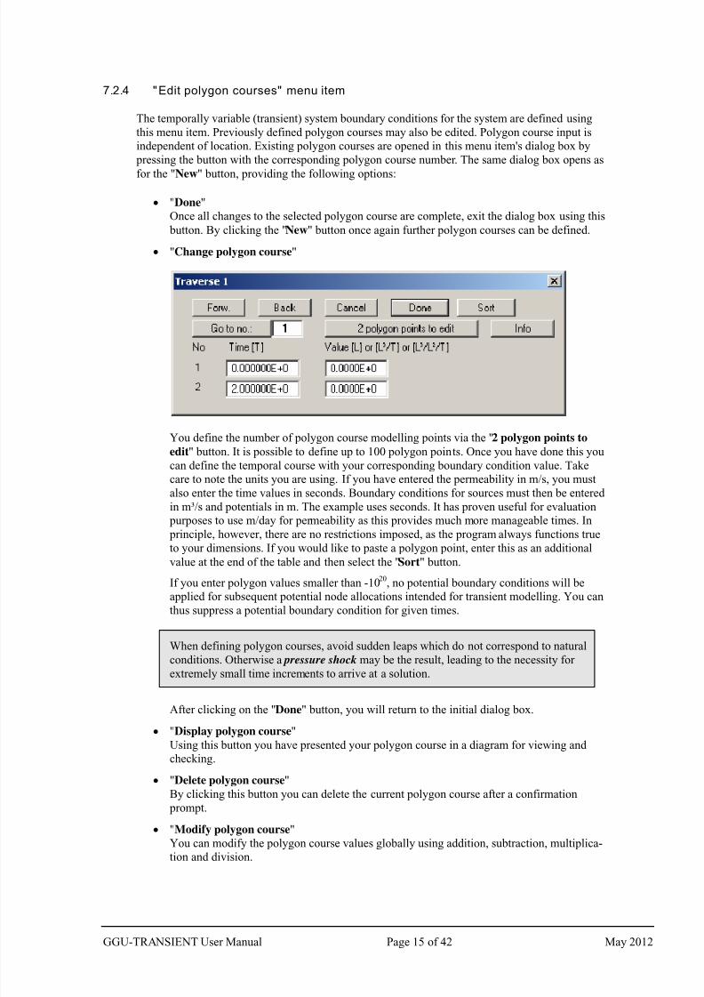
7.2.4 "Edit polygon courses" menu item
The temporally variable (transient) system boundary conditions for the system are defined using
this menu item. Previously defined polygon courses may also be edited. Polygon course input is
independent of location. Existing polygon courses are opened in this menu item's dialog box by
pressing the button with the corresponding polygon course number. The same dialog box opens as
for the "New" button, providing the following options:
"Done"
Once all changes to the selected polygon course are complete, exit the dialog box using this
button. By clicking the "New" button once again further polygon courses can be defined.
"Change polygon course"
You define the number of polygon course modelling points via the "2 polygon points to
edit" button. It is possible to define up to 100 polygon points. Once you have done this you
can define the temporal course with your corresponding boundary condition value. Take
care to note the units you are using. If you have entered the permeability in m/s, you must
also enter the time values in seconds. Boundary conditions for sources must then be entered
in m³/s and potentials in m. The example uses seconds. It has proven useful for evaluation
purposes to use m/day for permeability as this provides much more manageable times. In principle, however, there are no restrictions imposed, as the program always functions true
to your dimensions. If you would like to paste a polygon point, enter this as an additional
value at the end of the table and then select the "Sort" button.
If you enter polygon values smaller than -1020
, no potential boundary conditions will be
applied for subsequent potential node allocations intended for transient modelling. You can
thus suppress a potential boundary condition for given times.
When defining polygon courses, avoid sudden leaps which do not correspond to natural
conditions. Otherwise a pressure shock may be the result, leading to the necessity for
extremely small time increments to arrive at a solution.
After clicking on the "Done" button, you will return to the initial dialog box.
"Display polygon course"
Using this button you have presented your polygon course in a diagram for viewing and
checking.
"Delete polygon course"
By clicking this button you can delete the current polygon course after a confirmation
prompt.
"Modify polygon course"
You can modify the polygon course values globally using addition, subtraction, multiplica-
tion and division.
GGU-TRANSIENT User Manual Page 15 of 42 May 2012
7/29/2019 Ggu Transient Man e
http://slidepdf.com/reader/full/ggu-transient-man-e 16/42
"Load polygon course"
The data from a previously saved file can be loaded (e.g. from a previous project or a dif-
ferent system).
"Save polygon course"
The data entered can be saved to a file in order to have them available for different sys-
tems, for example.
"Import ASCII data"
If you have polygon course data available as an ASCII file, they can be imported into the
program.
"Export ASCII data"
The current polygon course can be exported to an ASCII file.
"Duplicate polygon course"
The data for the current polygon course are duplicated and allocated to a new polygon
course. You are then moved directly to the dialog box for the new polygon course and are
able to view, edit or delete the data by means of the corresponding buttons there (e.g. "x
polygon points to edit", see above).
"Polygon course via sinus function"This allows you to generate a polygon course via a sinus function. This can be useful for
areas under tidal influence for example.
"Copy polygon course to rear"
Existing polygon course points can be copied and appended to the end. This shortens input,
for example if two waves follow each other.
7.2.5 "Delete all" menu item
You can delete all polygon courses.
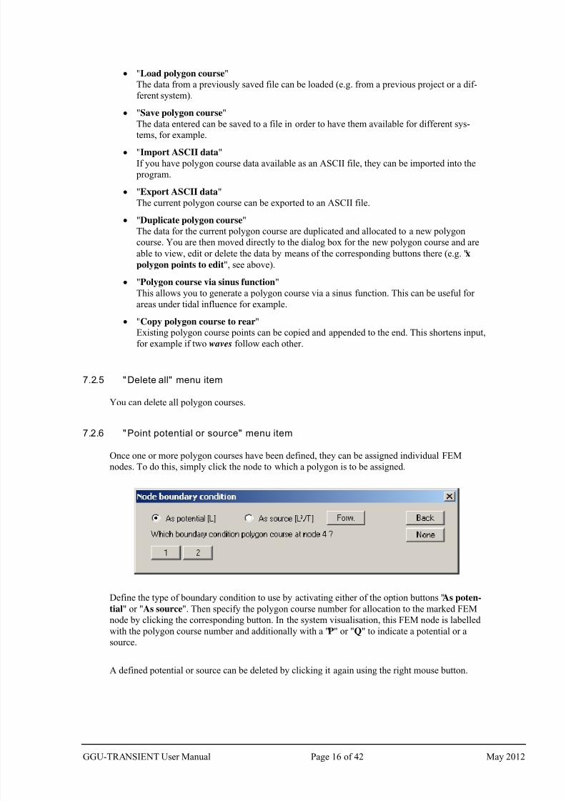
7.2.6 "Point potential or source" menu item
Once one or more polygon courses have been defined, they can be assigned individual FEM
nodes. To do this, simply click the node to which a polygon is to be assigned.
Define the type of boundary condition to use by activating either of the option buttons "As poten-
tial" or "As source". Then specify the polygon course number for allocation to the marked FEM
node by clicking the corresponding button. In the system visualisation, this FEM node is labelled
with the polygon course number and additionally with a "P" or "Q" to indicate a potential or a
source.
A defined potential or source can be deleted by clicking it again using the right mouse button.
GGU-TRANSIENT User Manual Page 16 of 42 May 2012
7/29/2019 Ggu Transient Man e
http://slidepdf.com/reader/full/ggu-transient-man-e 17/42
7.2.7 " (Potential or source) In section" menu item
After going to this menu item, time-dependent potentials or sources can be defined or deleted for
several FEM nodes simultaneously by assigning them a polygon course. Define the section by
clicking four points in an anti-clockwise direction. Use the right mouse button to undo. The defini-
tion refers to all nodes within the quadrilateral. If the "Define" button is pressed the same dialog
box opens as for "Time BC/Point potential or source" (see Section 7.2.6).
7.2.8 "Linear (potential or source)" menu item
After going to this menu item click the nodes of the FEM mesh to which time-dependent, linearly
variable potentials or sources are to be assigned by means of a polygon course. Press the [Return]
key and enter a start and an end polygon course. The program subsequently generates new poly-
gon courses by linear interpolation of the spacing of the system nodes and assigns these to the
corresponding nodes. This menu item can be helpful for defining a receiving watercourse (hori-
zontal-plane system) if its water level is linearly variable within the system.
7.2.9 "Linear sources" menu item
The procedure for defining time-dependent linear sources is explained in a dialog box. After click-
ing system nodes and confirming the selection using the [Return] key, a dialog opens for select-
ing a polygon course.
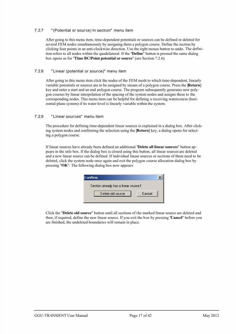
If linear sources have already been defined an additional "Delete all linear sources" button ap-
pears in the info box. If the dialog box is closed using this button, all linear sources are deleted
and a new linear source can be defined. If individual linear sources or sections of them need to be
deleted, click the system node once again and exit the polygon course allocation dialog box by
pressing "OK". The following dialog box now appears:
Click the "Delete old source" button until all sections of the marked linear source are deleted and
then, if required, define the new linear source. If you exit the box by pressing "Cancel" before you
are finished, the undeleted boundaries will remain in place.
GGU-TRANSIENT User Manual Page 17 of 42 May 2012
7/29/2019 Ggu Transient Man e
http://slidepdf.com/reader/full/ggu-transient-man-e 18/42
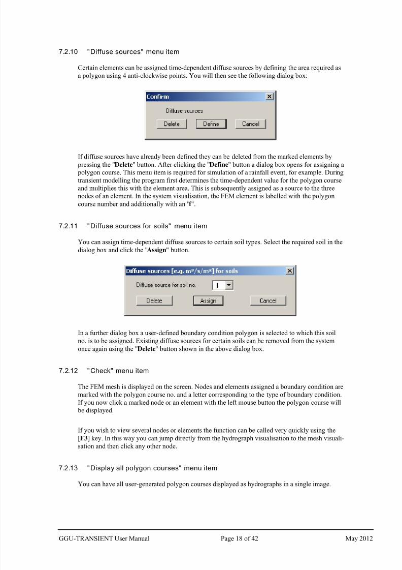
7.2.10 "Diffuse sources" menu item
Certain elements can be assigned time-dependent diffuse sources by defining the area required as
a polygon using 4 anti-clockwise points. You will then see the following dialog box:
If diffuse sources have already been defined they can be deleted from the marked elements by
pressing the "Delete" button. After clicking the "Define" button a dialog box opens for assigning a
polygon course. This menu item is required for simulation of a rainfall event, for example. During
transient modelling the program first determines the time-dependent value for the polygon course
and multiplies this with the element area. This is subsequently assigned as a source to the three
nodes of an element. In the system visualisation, the FEM element is labelled with the polygon
course number and additionally with an "f ".
7.2.11 "Diffuse sources for soils" menu item
You can assign time-dependent diffuse sources to certain soil types. Select the required soil in the
dialog box and click the "Assign" button.
In a further dialog box a user-defined boundary condition polygon is selected to which this soil
no. is to be assigned. Existing diffuse sources for certain soils can be removed from the system
once again using the "Delete" button shown in the above dialog box.
7.2.12 "Check" menu item
The FEM mesh is displayed on the screen. Nodes and elements assigned a boundary condition are
marked with the polygon course no. and a letter corresponding to the type of boundary condition.
If you now click a marked node or an element with the left mouse button the polygon course will
be displayed.
If you wish to view several nodes or elements the function can be called very quickly using the
[F3] key. In this way you can jump directly from the hydrograph visualisation to the mesh visuali-
sation and then click any other node.
7.2.13 "Display all polygon courses" menu item
You can have all user-generated polygon courses displayed as hydrographs in a single image.
GGU-TRANSIENT User Manual Page 18 of 42 May 2012
7/29/2019 Ggu Transient Man e
http://slidepdf.com/reader/full/ggu-transient-man-e 19/42
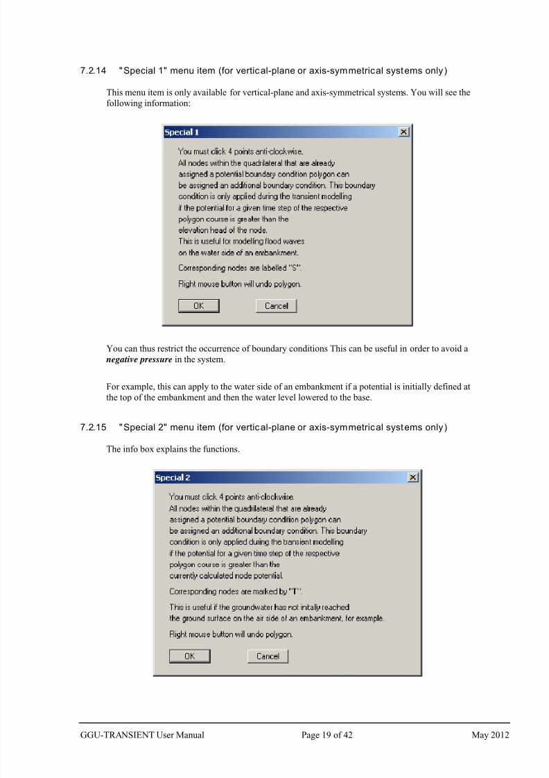
7.2.14 "Special 1" menu item (for vertical-plane or axis-symmetrical systems only)
This menu item is only available for vertical-plane and axis-symmetrical systems. You will see the
following information:
You can thus restrict the occurrence of boundary conditions This can be useful in order to avoid a
negative pressure in the system.
For example, this can apply to the water side of an embankment if a potential is initially defined at
the top of the embankment and then the water level lowered to the base.
7.2.15 "Special 2" menu item (for vertical-plane or axis-symmetrical systems only)
The info box explains the functions.
GGU-TRANSIENT User Manual Page 19 of 42 May 2012
7/29/2019 Ggu Transient Man e
http://slidepdf.com/reader/full/ggu-transient-man-e 20/42
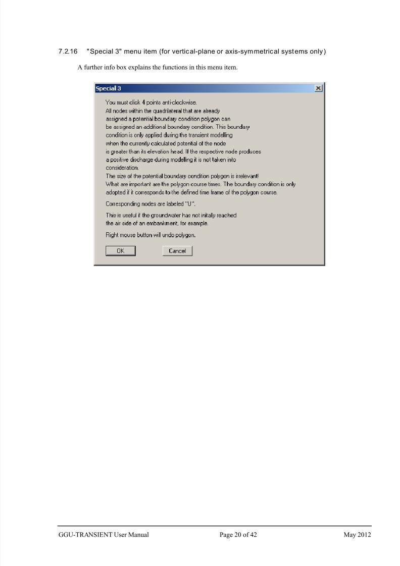
7.2.16 "Special 3" menu item (for vertical-plane or axis-symmetrical systems only)
A further info box explains the functions in this menu item.
GGU-TRANSIENT User Manual Page 20 of 42 May 2012
7/29/2019 Ggu Transient Man e
http://slidepdf.com/reader/full/ggu-transient-man-e 21/42
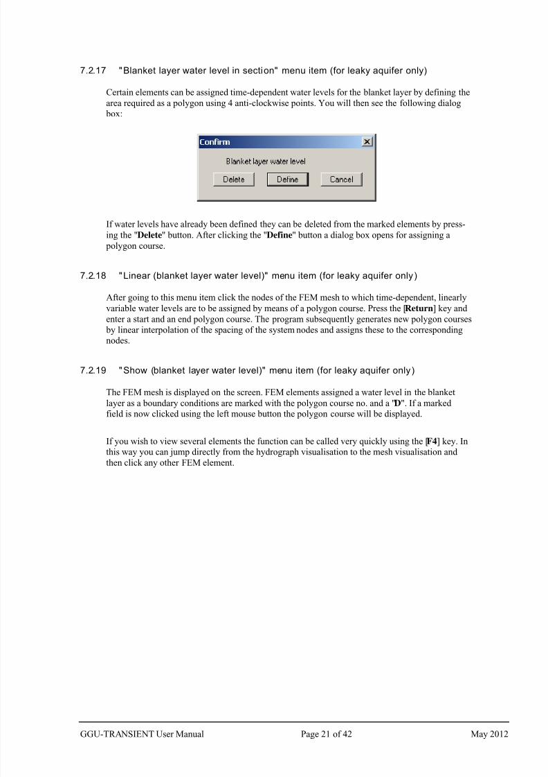
7.2.17 "Blanket layer water level in section" menu item (for leaky aquifer only)
Certain elements can be assigned time-dependent water levels for the blanket layer by defining the
area required as a polygon using 4 anti-clockwise points. You will then see the following dialog
box:
If water levels have already been defined they can be deleted from the marked elements by press-
ing the "Delete" button. After clicking the "Define" button a dialog box opens for assigning a
polygon course.
7.2.18 "Linear (blanket layer water level)" menu item (for leaky aquifer only)
After going to this menu item click the nodes of the FEM mesh to which time-dependent, linearly
variable water levels are to be assigned by means of a polygon course. Press the [Return] key and
enter a start and an end polygon course. The program subsequently generates new polygon courses
by linear interpolation of the spacing of the system nodes and assigns these to the corresponding
nodes.
7.2.19 "Show (blanket layer water level)" menu item (for leaky aquifer only)
The FEM mesh is displayed on the screen. FEM elements assigned a water level in the blanket
layer as a boundary conditions are marked with the polygon course no. and a "D". If a marked
field is now clicked using the left mouse button the polygon course will be displayed.
If you wish to view several elements the function can be called very quickly using the [F4] key. In
this way you can jump directly from the hydrograph visualisation to the mesh visualisation and
then click any other FEM element.
GGU-TRANSIENT User Manual Page 21 of 42 May 2012
7/29/2019 Ggu Transient Man e
http://slidepdf.com/reader/full/ggu-transient-man-e 22/42
7.3 Fixed BC menu
7.3.1 General notes on " fixed" boundary conditions
The GGU-TRANSIENT program also imports the steady-state boundary conditions from the
steady-state modelling record (henceforth also known as fixed boundary conditions). When
analysing transient systems it is almost always the case that at least parts of these boundary
conditions remain constant for the complete investigation duration. In principle, you could define
the appropriate boundary condition polygons and assign nodes to these. However, this is onerous
and superfluous. For this reason the program initially assumes all steady-state boundary conditions
as being temporally constant. Naturally, if nodes are then assigned a boundary condition polygon,
the temporal constancy at this node is deleted. If a node boundary condition is not to be applied
during transient modelling, you must delete the fixed boundary condition (see below).
Do not misuse the fixed boundary conditions to assign a substantially different boundary
condition value than that which applied in the steady-state condition. Otherwise a pressure
shock may be the result, leading to the necessity for extremely small time increments to
arrive at a solution. It is better to define a boundary condition polygon for the appropriatenodes with smooth transitions, which correspond better to the naturally occurring
conditions.
7.3.2 "Preferences" menu item
Here you can specify preferences for the type of presentation for fixed boundary potentials or
fixed sources at the node points. This includes the font size selection and the type of numerical
presentation (decimal places).
7.3.3 "Check" menu item
Here you can check the type of temporally fixed boundary condition defined at each node.
7.3.4 "Point potential or source" menu item
After selecting this menu item a descriptive dialog box opens, followed by the screen presentation
of the system mesh with the previously defined fixed boundary conditions. By clicking with the
right mouse button you can delete fixed boundary conditions, similarly to the time boundary con-
ditions. By clicking with the left mouse button you can define potentials or sources, similarly to
the time boundary conditions, which remain constant for the analysis duration. In the subsequent
dialog box you define the value and type of boundary condition. However, please observe the
remark above (see Section 7.3.1).
7.3.5 " In section" menu item
Using this menu item you can define or delete potentials or sources in section. As described in the
dialog box, click on a section with four points in an anti-clockwise direction using the left mouse
button and then enter the type and value of the boundary condition. The definition then applies to
the nodes within the section.
7.3.6 "Linear sources" menu item
The procedure for defining linear sources is explained in a dialog box. Further information can befound in the menu item "Time BC/Linear sources" (see Section 7.2.9).
GGU-TRANSIENT User Manual Page 22 of 42 May 2012
7/29/2019 Ggu Transient Man e
http://slidepdf.com/reader/full/ggu-transient-man-e 23/42
7.3.7 "Diffuse sources" menu item
Certain elements can be assigned fixed diffuse sources by defining the area required as a polygon
using 4 counter-clockwise points. You will then see a dialog box in which existing diffuse sources
can be deleted from the marked elements by pressing the "Delete" button. After clicking the "De-
fine" button a dialog box opens for entering the value for the diffuse source.
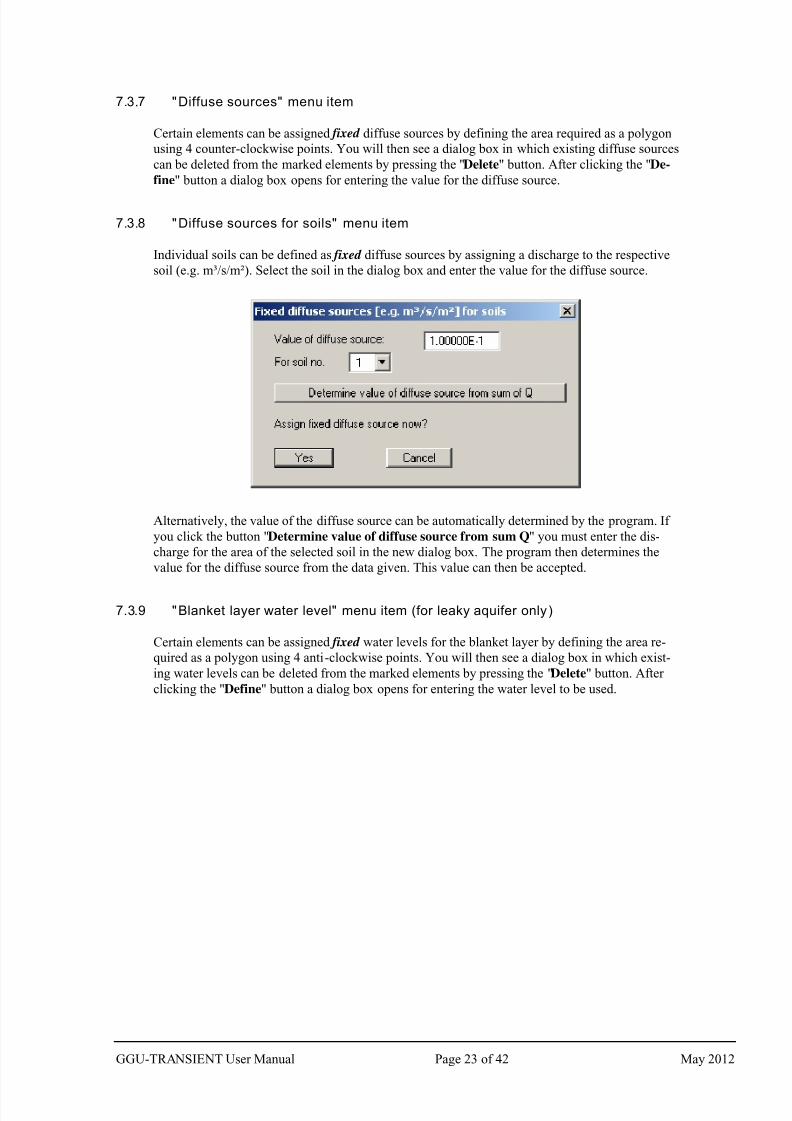
7.3.8 "Diffuse sources for soils" menu item
Individual soils can be defined as fixed diffuse sources by assigning a discharge to the respective
soil (e.g. m³/s/m²). Select the soil in the dialog box and enter the value for the diffuse source.
Alternatively, the value of the diffuse source can be automatically determined by the program. If
you click the button "Determine value of diffuse source from sum Q" you must enter the dis-
charge for the area of the selected soil in the new dialog box. The program then determines the
value for the diffuse source from the data given. This value can then be accepted.
7.3.9 "Blanket layer water level" menu item (for leaky aquifer only)
Certain elements can be assigned fixed water levels for the blanket layer by defining the area re-
quired as a polygon using 4 anti-clockwise points. You will then see a dialog box in which exist-
ing water levels can be deleted from the marked elements by pressing the "Delete" button. After
clicking the "Define" button a dialog box opens for entering the water level to be used.
GGU-TRANSIENT User Manual Page 23 of 42 May 2012
7/29/2019 Ggu Transient Man e
http://slidepdf.com/reader/full/ggu-transient-man-e 24/42
7.4 Check menu
7.4.1 General note
The menu items in this menu serve to check the transient data and to aid your memory. You can
have the mesh presented on the screen together with the desired parameters. With the following
menu items you cannot edit any of the mesh analysis parameters.
7.4.2 "Preferences" menu item
In this dialog box you can specify preferences for the FEM mesh presentation.
7.4.3 "Mesh" menu item
When you select this menu item the FEM mesh is displayed.
7.4.4 "Outline" menu item
When you select this menu item the system outline is displayed.
7.4.5 "Outline (coloured)" menu item
After going to this menu item the system is outlined and the soil colours displayed.
7.4.6 "Contours" menu item
After going to this menu item the contours of the potentials for the initial steady-state are dis-
played. A dialog box opens, in which the type of visualisation can be specified.
The program shows you the existing smallest and largest values and the spacing of the contour
lines. If you want the visualisation to begin at a different value, the initial value can be entered
here. You can also vary the spacing, for example, in order to reduce the number of contour lines
drawn.
When you select this menu item the settings displayed here are always those automatically se-
lected by the program. Using the "Old values" button, the preferences used for the previous con-
tour line diagram are adopted. This information is saved with the record.
You can also select from three smoothing out procedures:
"Do not smooth"
As a linear method is implemented within the triangle elements, this will provide modelling
results without smoothing performed by the program.
"Method 1" and "Method 2"
these smoothing out procedures employ two different Bezier splines. Smoothing out inten-
sities can be given for both in order to acquire smooth contour lines. Method 2 creates very
"round" contours, with the danger that the true results may be falsified.
The "Further preferences" button can be used to specify the type of visualisation of the contour
lines and labelling.
GGU-TRANSIENT User Manual Page 24 of 42 May 2012
7/29/2019 Ggu Transient Man e
http://slidepdf.com/reader/full/ggu-transient-man-e 25/42
7.4.7 "Contours (coloured)" menu item
After going to this menu item the contours of the potentials for the initial steady-state are dis-
played in colour. The following preferences can be defined in the dialog:
"Contour data" group box
Press the "Determine extreme values…" button. The program then determines the mini-mum and maximum values for the corresponding layer base. You can then edit these val-
ues, for example in order achieve a defined start value.
"Colour fill" group box
You can control the colour subdivisions of the contour diagram using "No. of colours". In
the example above, 16 colours will be displayed between "Colour 1" and "Colour 2". The
default setting is a colour course from red to blue. These colours can be edited as required
after selecting the "Colour 1" and "Colour 2" buttons, or simply reverse the choice by se-
lecting the "Change colour series" check box.
"Further preferences" group box
In addition to the colour presentation you can also have the triangle mesh and/or the outline
displayed. Additional contour lines can also be drawn. Line labelling preferences can be
defined by means of the "Labelling preferences" button.
"OK"
The colours will be drawn after confirmation.
A colour bar at the right edge of the sheet allows correlation between the colour and the corre-
sponding value. If this colour bar is drawn in the right page margin, specify a larger value for the
right plotting margin (e.g. 25 mm) in the "Page size + margins/Page size and margins" menu
item (see Section 7.7.5).
GGU-TRANSIENT User Manual Page 25 of 42 May 2012
7/29/2019 Ggu Transient Man e
http://slidepdf.com/reader/full/ggu-transient-man-e 26/42
7.5 Modelling menu
7.5.1 "Start" menu item
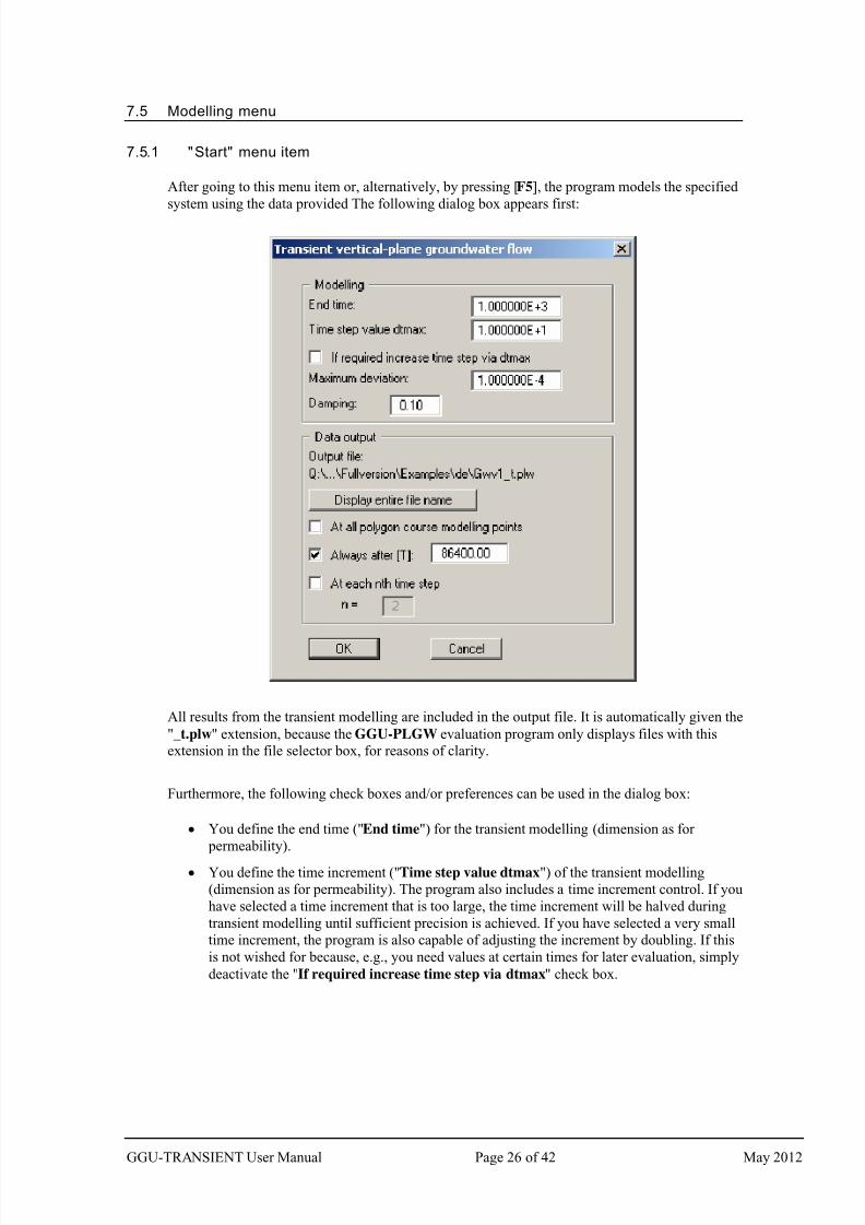
After going to this menu item or, alternatively, by pressing [F5], the program models the specified
system using the data provided The following dialog box appears first:
All results from the transient modelling are included in the output file. It is automatically given the
"_t.plw" extension, because the GGU-PLGW evaluation program only displays files with this
extension in the file selector box, for reasons of clarity.
Furthermore, the following check boxes and/or preferences can be used in the dialog box:
You define the end time ("End time") for the transient modelling (dimension as for
permeability).
You define the time increment ("Time step value dtmax") of the transient modelling
(dimension as for permeability). The program also includes a time increment control. If you
have selected a time increment that is too large, the time increment will be halved during
transient modelling until sufficient precision is achieved. If you have selected a very small
time increment, the program is also capable of adjusting the increment by doubling. If this
is not wished for because, e.g., you need values at certain times for later evaluation, simply
deactivate the "If required increase time step via dtmax" check box.
GGU-TRANSIENT User Manual Page 26 of 42 May 2012
7/29/2019 Ggu Transient Man e
http://slidepdf.com/reader/full/ggu-transient-man-e 27/42
Iteration is necessary for every time increment. If the deviation of the potentials between
the iteration steps (i) and (i - 1) is smaller than the "Maximum deviation", the program
will jump to the next time increment. Maximum deviation values of 0.0001 are generally
sufficient.
You have the option of specifying a "Damping" value. During phreatic line modelling in
complicated groundwater systems, oscillation around the actual solution can occur. This
oscillation is damped by the damping factor. Values between 0.0 and 0.95 make the most
sense. A value of 1.0 (complete damping) is nonsense and will therefore not be accepted by
the program.
A flood of results is usually the consequence of transient modelling, with correspondingly
large result files. Often, a small time increment must be selected in order to achieve
sufficiently precise results. You can therefore specify in the "Data output" group box the
times at which data output should follow.
During modelling, the program automatically proceeds to all times associated with bound-
ary polygons, regardless of the selected time step. If you activate the "At all polygon
course modelling points" check box, the results for all times will be given additionally to
the usual input. So data output can either be at all polygon course output points, at a user-
definable time [T], or at each desired (nth
) time increment. These three options can also becombined with one another. It is conceivable, for example, to enter a very large value for
data output "At each nth time step" and to temporally subdivide a boundary condition
polygon such that output only occurs at the user-defined times.
Because long paths are shown shortened in the dialog box, the "Display entire file name"
button can be clicked before commencing modelling. The name of the file containing the
transient modelling data will then be displayed showing the complete path.
Once all data has been entered, start modelling by clicking "OK". During modelling, a dialog box
appears with information on modelling progress. It is also provided with a "Cancel" button. If you
press this button, modelling will not cease immediately, but instead you can edit specific program
data such as maximum deviation, time step, etc. and then carry on modelling.
A record with the extension "_t.plw" is generated for the evaluation application during modelling.
If, after commencing modelling, you open the GGU-PLGW program, you can check and evaluate
the current results while modelling is still in progress. The "Animation" function is particularly
impressive here; it can be executed parallel to the running modelling process.
GGU-TRANSIENT User Manual Page 27 of 42 May 2012
7/29/2019 Ggu Transient Man e
http://slidepdf.com/reader/full/ggu-transient-man-e 28/42
7.6 Graphics preferences menu
7.6.1 "Refresh and zoom" menu item
The program works on the principle of What you see is what you get. This means that the screen
presentation represents, overall, what you will see on your printer. In the last consequence, this
would mean that the screen presentation would have to be refreshed after every alteration you
make. For reasons of efficiency and as this can take several seconds for complex screen contents,
the screen is not refreshed after every alteration.
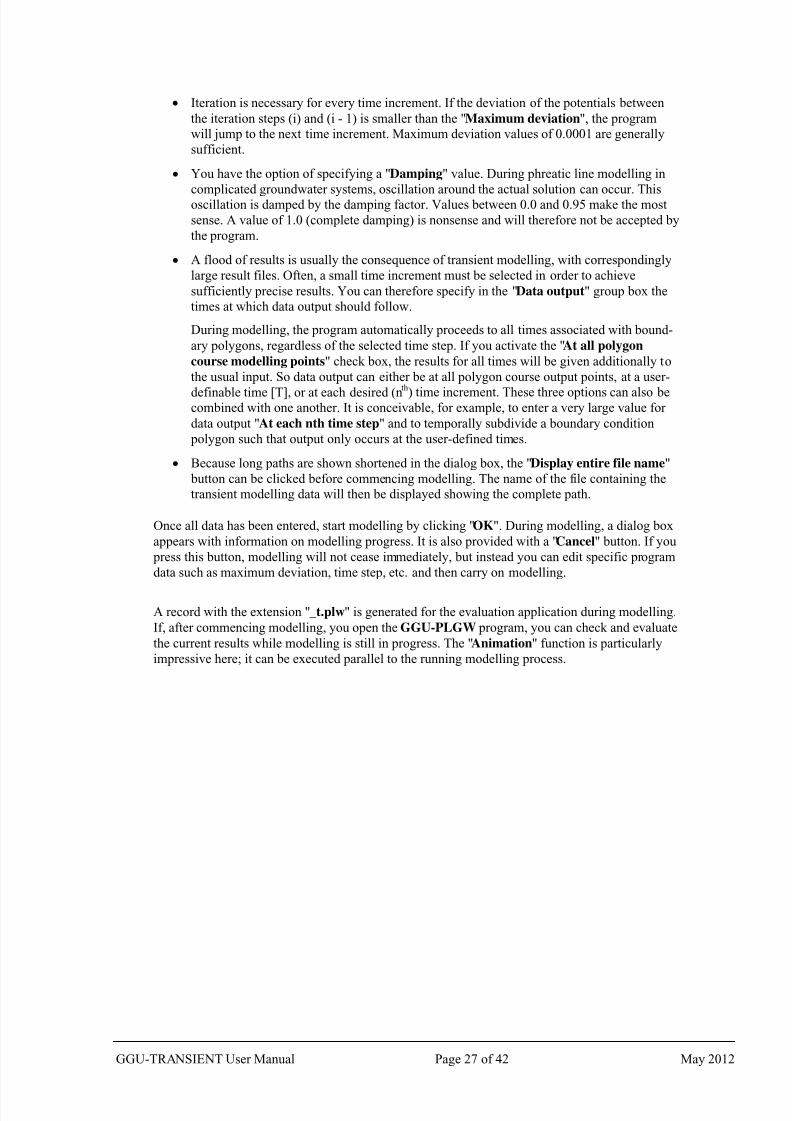
If, e.g., after using the zoom function (see below), only part of the image is visible, you can
achieve a complete view using this menu item.
A zoom factor between 0.4 and 8.0 can be entered in the input box. By then clicking on "Use" to
exit the box the current factor is accepted. By clicking on the "0.4", "0.6", etc. buttons, the se-
lected factor is used directly and the dialog box closed.
It is much simpler, however, to get a complete overview using [Esc]. Pressing [Esc] allows a com-
plete screen presentation using the zoom factor specified in this menu item. The [F2] key allows
screen refreshing without altering the coordinates and zoom factor.
7.6.2 "Zoom info" menu item
By clicking two diametrically opposed points you can enlarge a section of the screen in order to
view details better. An information box provides information on activating the zoom function and
on available options.
7.6.3 "Pen colour and width" menu item
In order to enhance the clarity of the graphics you can edit the pen settings for various graphic
elements (e.g. potential, sources, etc.). You can edit the pen widths for the elements shown in the
dialog box; by clicking on the button with the element designation you can also edit the pen or fillcolours.
On monochrome printers (e.g. laser printers), colours are shown in a corresponding grey scale.
Graphic elements employing very light colours may be difficult to see. In such cases it makes
sense to edit the colour preferences.
7.6.4 "Legend font selection" menu item
With this menu item you can switch to a different true-type font. All available true-type fonts are
displayed in the dialog box.
GGU-TRANSIENT User Manual Page 28 of 42 May 2012
7/29/2019 Ggu Transient Man e
http://slidepdf.com/reader/full/ggu-transient-man-e 29/42
7.6.5 "Mini-CAD toolbar" and "Header toolbar" menu items
Using these two menu items you can add free text to the graphics and add lines, circles, polygons
and images (e.g. files in formats BMP, JPG, PSP, TIF, etc.). The same pop-up menu opens for
both menu items, the icons and functions used are described in more detail in the Mini-CAD
manual provided. The differences between the Mini-CAD and Header CAD are as follows:
Objects created with Mini-CAD are based on the coordinate system (generally in metres),
in which the drawing is produced, and are shown accordingly. You should use the "Mini-
CAD toolbar" when you wish to add information to the system (for example, labelling of
slope inclinations or the location of any foundations).
Objects created with the Header CAD are based on the page format (in mm). This makes
you independent of the coordinate system and keeps you in the same position on the page.
You should select the "Header toolbar" if you wish to place general information on the
drawing (company logo, report numbers, plan numbers, stamp etc.). Once you have saved
the header information to disk (see Mini-CAD user manual), you can load it into com-
pletely different systems (with different system coordinates). The saved header information
will appear in exactly the same position on the page, which greatly simplifies the creation
of general page information.
7.6.6 "Toolbar preferences" menu item
After starting the program a horizontal toolbar for menu items appears below the program menu
bar. If you would rather work with a popup window with several columns, you can specify your
preferences using this menu item. The smart icons can also be switched off.
At the bottom of the program window you find a status bar with further information. You can also
activate or switch off the status bar here. The preferences will be saved in the "GGU-
TRANSIENT.alg" file (see menu item "Graphics preferences/Save graphics preferences") and
will be active at the next time the program is started.
By clicking on the tools (smart icons) for the menu items you can directly reach most of the pro-
gram functions. The meaning of the smart icons appears as a text box if you hover with the mouse
pointer over the tools. Some of the tool functions cannot be activated from the normal menu items.
"Copy/print area"
Use this tool to copy only parts of the graphics in order to paste them, e.g. to a report. You will see
information on this function and can then mark an area, which is copied to the clipboard or can be
saved in a file. Alternatively you can send the marked area directly to your printer (see "Tips and
tricks", Section 8.3).
GGU-TRANSIENT User Manual Page 29 of 42 May 2012
7/29/2019 Ggu Transient Man e
http://slidepdf.com/reader/full/ggu-transient-man-e 30/42
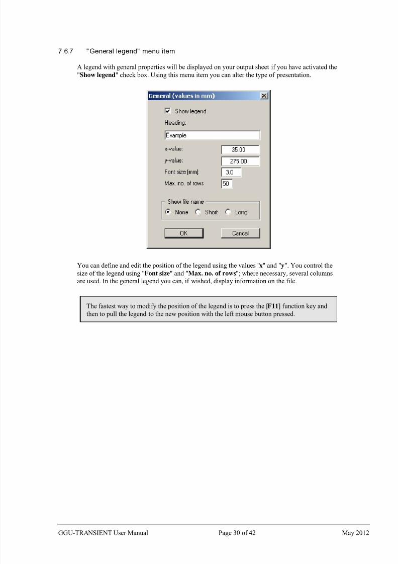
7.6.7 "General legend" menu item
A legend with general properties will be displayed on your output sheet if you have activated the
"Show legend" check box. Using this menu item you can alter the type of presentation.
You can define and edit the position of the legend using the values "x" and "y". You control the
size of the legend using "Font size" and "Max. no. of rows"; where necessary, several columns
are used. In the general legend you can, if wished, display information on the file.
The fastest way to modify the position of the legend is to press the [F11] function key and
then to pull the legend to the new position with the left mouse button pressed.
GGU-TRANSIENT User Manual Page 30 of 42 May 2012
7/29/2019 Ggu Transient Man e
http://slidepdf.com/reader/full/ggu-transient-man-e 31/42
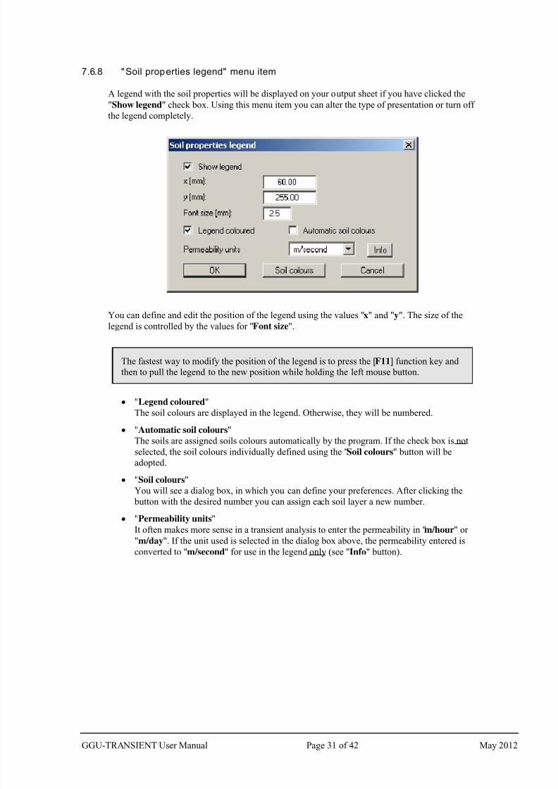
7.6.8 "Soil properties legend" menu item
A legend with the soil properties will be displayed on your output sheet if you have clicked the
"Show legend" check box. Using this menu item you can alter the type of presentation or turn off
the legend completely.
You can define and edit the position of the legend using the values "x" and "y". The size of the
legend is controlled by the values for "Font size".
The fastest way to modify the position of the legend is to press the [F11] function key and
then to pull the legend to the new position while holding the left mouse button.
"Legend coloured"
The soil colours are displayed in the legend. Otherwise, they will be numbered.
"Automatic soil colours"
The soils are assigned soils colours automatically by the program. If the check box is not
selected, the soil colours individually defined using the "Soil colours" button will be
adopted.
"Soil colours"
You will see a dialog box, in which you can define your preferences. After clicking the
button with the desired number you can assign each soil layer a new number.
"Permeability units"
It often makes more sense in a transient analysis to enter the permeability in "m/hour" or
"m/day". If the unit used is selected in the dialog box above, the permeability entered is
converted to "m/second" for use in the legend only (see "Info" button).
GGU-TRANSIENT User Manual Page 31 of 42 May 2012
7/29/2019 Ggu Transient Man e
http://slidepdf.com/reader/full/ggu-transient-man-e 32/42
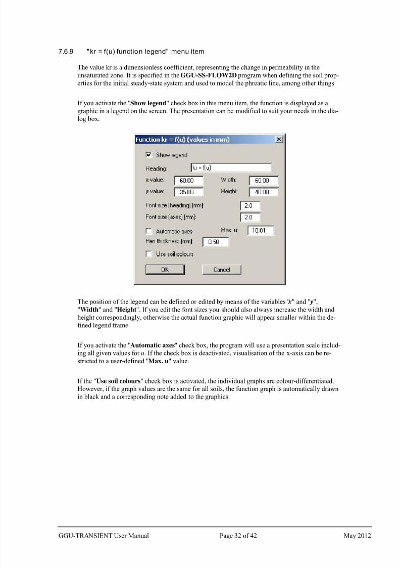
7.6.9 "kr = f(u) function legend" menu item
The value kr is a dimensionless coefficient, representing the change in permeability in the
unsaturated zone. It is specified in the GGU-SS-FLOW2D program when defining the soil prop-
erties for the initial steady-state system and used to model the phreatic line, among other things.
If you activate the "Show legend" check box in this menu item, the function is displayed as a
graphic in a legend on the screen. The presentation can be modified to suit your needs in the dia-
log box.
The position of the legend can be defined or edited by means of the variables " x" and " y",
"Width" and "Height". If you edit the font sizes you should also always increase the width and
height correspondingly, otherwise the actual function graphic will appear smaller within the de-
fined legend frame.
If you activate the "Automatic axes" check box, the program will use a presentation scale includ-
ing all given values for u. If the check box is deactivated, visualisation of the x-axis can be re-
stricted to a user-defined "Max. u" value.
If the "Use soil colours" check box is activated, the individual graphs are colour-differentiated.
However, if the graph values are the same for all soils, the function graph is automatically drawn
in black and a corresponding note added to the graphics.
GGU-TRANSIENT User Manual Page 32 of 42 May 2012
7/29/2019 Ggu Transient Man e
http://slidepdf.com/reader/full/ggu-transient-man-e 33/42
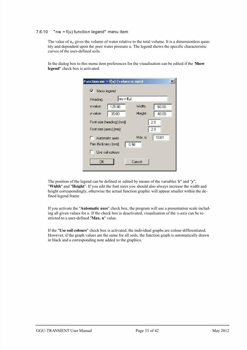
7.6.10 "nw = f(u) function legend" menu item
The value of nw gives the volume of water relative to the total volume. It is a dimensionless quan-
tity and dependent upon the pore water pressure u. The legend shows the specific characteristic
curves of the user-defined soils.
In the dialog box to this menu item preferences for the visualisation can be edited if the "Show
legend" check box is activated.
The position of the legend can be defined or edited by means of the variables " x" and " y",
"Width" and "Height". If you edit the font sizes you should also always increase the width and
height correspondingly, otherwise the actual function graphic will appear smaller within the de-
fined legend frame.
If you activate the "Automatic axes" check box, the program will use a presentation scale includ-
ing all given values for u. If the check box is deactivated, visualisation of the x-axis can be re-
stricted to a user-defined "Max. u" value.
If the "Use soil colours" check box is activated, the individual graphs are colour-differentiated.
However, if the graph values are the same for all soils, the function graph is automatically drawn
in black and a corresponding note added to the graphics.
GGU-TRANSIENT User Manual Page 33 of 42 May 2012
7/29/2019 Ggu Transient Man e
http://slidepdf.com/reader/full/ggu-transient-man-e 34/42
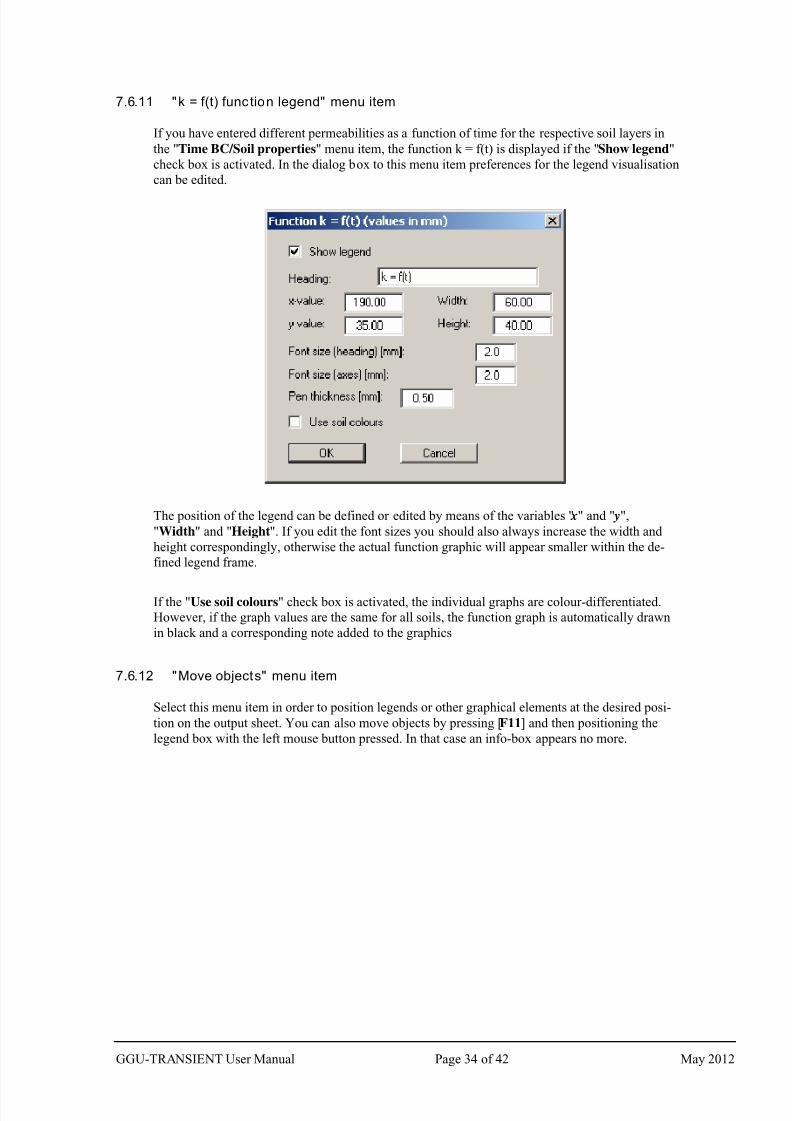
7.6.11 "k = f(t) function legend" menu item
If you have entered different permeabilities as a function of time for the respective soil layers in
the "Time BC/Soil properties" menu item, the function k = f(t) is displayed if the "Show legend"
check box is activated. In the dialog box to this menu item preferences for the legend visualisation
can be edited.
The position of the legend can be defined or edited by means of the variables " x" and " y",
"Width" and "Height". If you edit the font sizes you should also always increase the width and
height correspondingly, otherwise the actual function graphic will appear smaller within the de-
fined legend frame.
If the "Use soil colours" check box is activated, the individual graphs are colour-differentiated.
However, if the graph values are the same for all soils, the function graph is automatically drawn
in black and a corresponding note added to the graphics
7.6.12 "Move objects" menu item
Select this menu item in order to position legends or other graphical elements at the desired posi-
tion on the output sheet. You can also move objects by pressing [F11] and then positioning the
legend box with the left mouse button pressed. In that case an info-box appears no more.
GGU-TRANSIENT User Manual Page 34 of 42 May 2012
7/29/2019 Ggu Transient Man e
http://slidepdf.com/reader/full/ggu-transient-man-e 35/42
7.6.13 "Save graphics preferences" menu item
Some of the preferences you made with the menu items of the "Graphics preferences" menu can
be saved to a file. If you select "GGU-TRANSIENT.alg" as file name, and save the file on the
same level as the program, the data will be automatically loaded the next time the program is star-
ted and need not be entered again.
If you do not go to "File/New" upon starting the program, but open a previously saved file
instead, the preferences used at the time of saving are shown. If subsequent changes in the
general preferences are to be used for existing files, these preferences must be imported us-
ing the menu item "Graphics preferences/Load graphics preferences".
7.6.14 "Load graphics preferences" menu item
You can reload a graphics preferences file into the program, which was saved using the "Graph-
ics preferences/Save graphics preferences" menu item. Only the corresponding data will be
refreshed.
7.7 Page size + margins menu
7.7.1 "Auto-resize" menu item
This menu item provides a to-scale visualisation, in both x- and y-coordinates, of the system and
result graphics. If you have previously altered the image coordinates graphically or via editor, you
can quickly achieve a complete view using this menu item. This function can also be accessed
using the [F9] function key.
7.7.2 "Manual resize (mouse)" menu item
You can use the coordinates of a section of the visualisation as the new image coordinates by
marking the desired area with the mouse, pressing the left mouse button and holding the [Ctrl]
and [Shift] keys. The scales of the x- and y-axes are adjusted accordingly. If the previous propor-
tions (scale x-direction/scale y-direction) need to be retained, the "Proportional section" check
box must be activated.
Alternatively, you can simply "Redefine origin" of the visualisation. The previous scale prefer-
ences are not affected by this.
7.7.3 "Manual resize (editor)" menu item
You can alter the image coordinates by direct numerical input in a dialog box. This allows precise
scale input. The coordinates refer to the drawing area. This can be defined in the "Page size +
margins/Page size and margins" menu item by means of the plot margins (see Section 7.7.5).
GGU-TRANSIENT User Manual Page 35 of 42 May 2012
7/29/2019 Ggu Transient Man e
http://slidepdf.com/reader/full/ggu-transient-man-e 36/42
7.7.4 "Font size selection" menu item
You can edit font sizes for labelling the various drawing elements.
The font sizes of text within legends are edited in the respective legend editor. Just double-click in
a legend to do this.
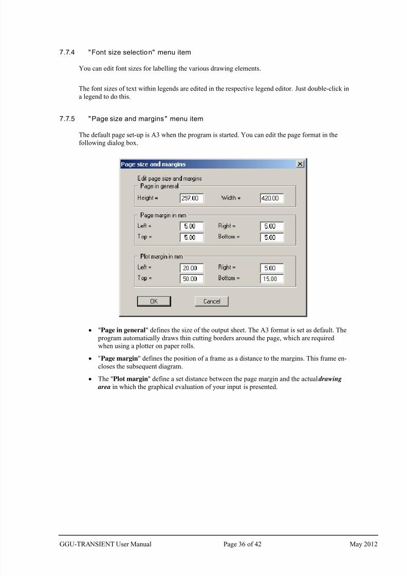
7.7.5 "Page size and margins" menu item
The default page set-up is A3 when the program is started. You can edit the page format in the
following dialog box.
"Page in general" defines the size of the output sheet. The A3 format is set as default. The
program automatically draws thin cutting borders around the page, which are required
when using a plotter on paper rolls.
"Page margin" defines the position of a frame as a distance to the margins. This frame en-
closes the subsequent diagram.
The "Plot margin" define a set distance between the page margin and the actual drawing
area in which the graphical evaluation of your input is presented.
GGU-TRANSIENT User Manual Page 36 of 42 May 2012
7/29/2019 Ggu Transient Man e
http://slidepdf.com/reader/full/ggu-transient-man-e 37/42
7.8 ? menu
7.8.1 "Copyright" menu item
You will see a copyright message and information on the program version number.
The "System" button shows information on your computer configuration and the folders used by
GGU-TRANSIENT. 7.8.2 "Maxima" menu item
A message box displays the program's default maximum number of nodes and the elements for the
FEM mesh, polygon courses and the times within the polygon courses.
7.8.3 "Help" menu item
The GGU-TRANSIENT manual is opened as a PDF document. The help function can also beaccessed using the [F1] function key.
7.8.4 "GGU on the web" menu item
Using this menu item you can access the GGU Software website: www.ggu-software.com.
Keep in touch with new program versions and the regular download offers.
If you would like to be automatically notified about program innovations, please register for the
Newsletter in our Knowledge Base. Go to the following website: http://kbase.civilserve.com.
7.8.5 "GGU support" menu item
This menu item takes to the GGU-Software Support area at www.ggu-software.com.
7.8.6 "What's new?" menu item
You will see information on program improvements in comparison to older versions.
7.8.7 "Language preferences" menu item
This menu item allows you to switch the menus and the graphics from German to English and vice
versa. To work in German, deactivate the two check boxes "Dialoge + Menüs übersetzen (trans-
late dialogs, menus)" und "Graphiktexte übersetzen (translate graphics)".
Alternatively, you can work bilingually, e.g. with German dialog boxes but with graphic output in
English. The program always starts with the language setting applicable when it was last ended.
GGU-TRANSIENT User Manual Page 37 of 42 May 2012
7/29/2019 Ggu Transient Man e
http://slidepdf.com/reader/full/ggu-transient-man-e 38/42
8 Tips and tricks
8.1 Keyboard and mouse
You can scroll the screen with the keyboard using the cursor keys and the [Page up] and [Page
down] keys. By clicking and pulling with the mouse, with [Ctrl] pressed, you activate the zoomfunction, i.e. the selected section will fill the screen. Use the mouse wheel to zoom in or out of the
screen view or to pan.
In addition, scale and coordinates of the system graphics (drawing area within the plotting mar-
gins) can be altered directly using the mouse wheel. The following mouse wheel functions are
available
Change system graphics (new values can be checked in "Page size + margins/Manual resize
(editor)"):
[Ctrl] + mouse wheel up = enlarge system graphics (change of scale)
[Ctrl] + mouse wheel down = shrink system graphics (change of scale)
[Shift] + mouse wheel up = move system graphics up
(change in system coordinates)
[Shift] + mouse wheel down = move system graphics down
(change in system coordinates)
[Shift] + [Ctrl] + mouse wheel up = move system graphics right
(change in system coordinates)
[Shift] + [Ctrl] + mouse wheel down = move system graphics left
(change in system coordinates)
Change screen coordinates:
Mouse wheel up = move screen image up
Mouse wheel down = move screen image down
[Alt] + [Ctrl] + mouse wheel up = enlarge screen image (zoom in)
[Alt] + [Ctrl] + mouse wheel down = shrink screen image (zoom out)
[Alt] + [Shift] + mouse wheel up = move screen image right
[Alt] + [Shift] + mouse wheel down = move screen image left
GGU-TRANSIENT User Manual Page 38 of 42 May 2012
7/29/2019 Ggu Transient Man e
http://slidepdf.com/reader/full/ggu-transient-man-e 39/42
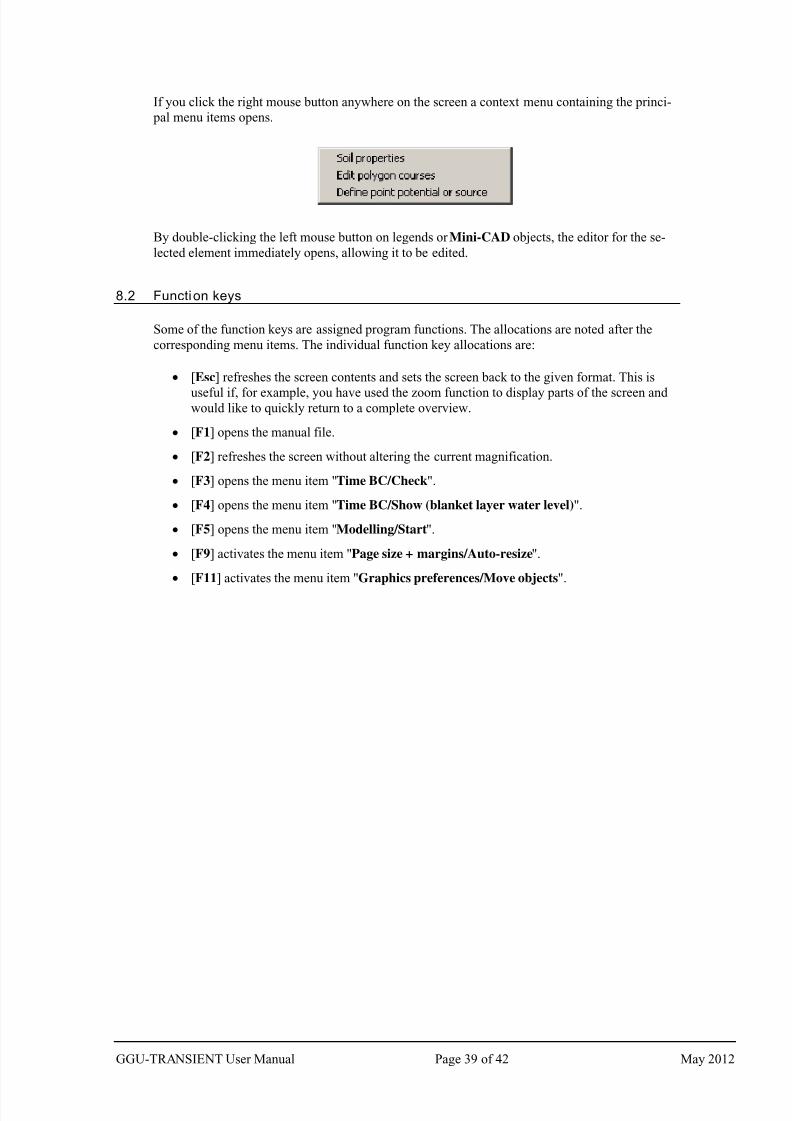
If you click the right mouse button anywhere on the screen a context menu containing the princi-
pal menu items opens.
By double-clicking the left mouse button on legends or Mini-CAD objects, the editor for the se-
lected element immediately opens, allowing it to be edited.
8.2 Function keys
Some of the function keys are assigned program functions. The allocations are noted after the
corresponding menu items. The individual function key allocations are:
[Esc] refreshes the screen contents and sets the screen back to the given format. This is
useful if, for example, you have used the zoom function to display parts of the screen and would like to quickly return to a complete overview.
[F1] opens the manual file.
[F2] refreshes the screen without altering the current magnification.
[F3] opens the menu item "Time BC/Check".
[F4] opens the menu item "Time BC/Show (blanket layer water level)".
[F5] opens the menu item "Modelling/Start".
[F9] activates the menu item "Page size + margins/Auto-resize".
[F11] activates the menu item "Graphics preferences/Move objects".
GGU-TRANSIENT User Manual Page 39 of 42 May 2012
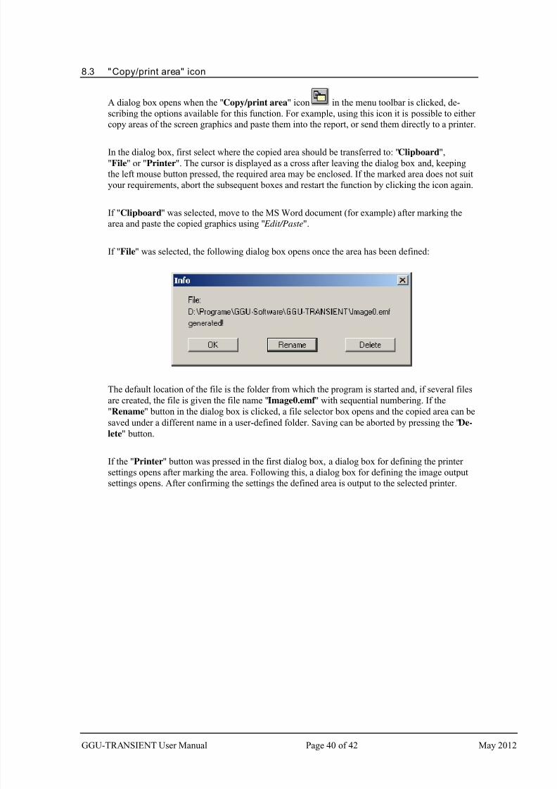
7/29/2019 Ggu Transient Man e
http://slidepdf.com/reader/full/ggu-transient-man-e 40/42
8.3 "Copy/print area" icon
A dialog box opens when the "Copy/print area" icon in the menu toolbar is clicked, de-
scribing the options available for this function. For example, using this icon it is possible to either
copy areas of the screen graphics and paste them into the report, or send them directly to a printer.
In the dialog box, first select where the copied area should be transferred to: "Clipboard",
"File" or "Printer". The cursor is displayed as a cross after leaving the dialog box and, keeping
the left mouse button pressed, the required area may be enclosed. If the marked area does not suit
your requirements, abort the subsequent boxes and restart the function by clicking the icon again.
If "Clipboard" was selected, move to the MS Word document (for example) after marking the
area and paste the copied graphics using " Edit/Paste".
If "File" was selected, the following dialog box opens once the area has been defined:
The default location of the file is the folder from which the program is started and, if several files
are created, the file is given the file name "Image0.emf " with sequential numbering. If the
"Rename" button in the dialog box is clicked, a file selector box opens and the copied area can besaved under a different name in a user-defined folder. Saving can be aborted by pressing the "De-
lete" button.
If the "Printer" button was pressed in the first dialog box, a dialog box for defining the printer
settings opens after marking the area. Following this, a dialog box for defining the image output
settings opens. After confirming the settings the defined area is output to the selected printer.
GGU-TRANSIENT User Manual Page 40 of 42 May 2012
7/29/2019 Ggu Transient Man e
http://slidepdf.com/reader/full/ggu-transient-man-e 41/42
9 Index
B
Base data, save ................................................. 10Boundary conditions, steady-state........ ............ 22
Boundary conditions, time-dependent ................ 7
C
Clipboard........... ........................ ....................... 12
CodeMeter stick.......................... ....................... . 6
Colour bar, define for contours......................... 25
Coloured contours, potentials initial
steady-state condition.............................. ..... 25
Colours, activate display in
soil properties legend ...................... ............. 31
Colours, define for soils.................................... 31
Colours/pens, define for graphical elements..... 28Company letterhead, add via Mini-CAD..... ..... 29
Context menu, open............ ........................ ...... 39
Contour lines, potentials initial steady-state
condition ...................................................... 24
Coordinates of graphics, alter via editor.... ....... 35
Coordinates of graphics, alter with mouse........ 35
Coordinates of graphics, optimise/reset..... ....... 35
Copy/print area....................... .............. 12, 29, 40
D
Damping, define ..................... ......................... . 27
Darcy's Law.......... ....................... ....................... 5
Data basis, for transient modelling..................... 5Delete, all polygon courses...................... ......... 16
Delete, fixed diffuse sources ......................... ... 23
Delete, fixed potentials/sources ........................ 22
Delete, individual polygon courses................... 15
Delete, linear sources....................................... . 23
Delete, time-dependent diffuse sources...... ...... 18
Delete, time-dependent linear sources..... ......... 17
Delete, time-dependent potentials/sources ....... 16
Diffuse sources, define/delete for certain soils. 18
Diffuse sources, define/delete time-dependent . 18
Drawing area, define ...................... .................. 36
DXF file, export.................................. .............. 11
E EMF format ...................... ....................... ......... 12
F
FEM mesh, show maximum number of
elements/nodes ........................ ..................... 37
File, display name in legend....................... ...... 30
File, save........................... ........................ ........ 10
Fixed BC, visualisation preferences ................. 22
Fixed diffuse sources, define for certain soils .. 23
Fixed diffuse sources, define/delete for
certain FEM elements .................................. 23
Fixed linear sources, define/delete ................... 23
Fixed potentials/sources, define/delete for
individual FEM nodes........................ .......... 22
Fixed potentials/sources, define/delete for
several FEM nodes.......... ....................... ...... 22
Fixed water level for blanket layer, define/
delete........................ ........................ ............ 23
Font selection.................................. .................. 28
Font size, define for drawing elements............. 36
Font size, define for general legend.................. 30
Font size, define for k = f(t) legend.................. 34
Font size, define for kr = f(u) legend................ 32
Font size, define for nw = f(u) legend .............. 33
Font size, define for soil properties legend....... 31
Function k = f(t), define.................................... 13
Function k = f(t), display in legend .................. 34
Function keys ................................................... 39
Function kr = f(u), display in legend................ 32
Function nw = f(u), define......................... ....... 14
Function nw = f(u), display in legend............... 33
G
General page information, add via
Mini-CAD........................ ....................... ..... 29
GGUCAD file, export............................ ........... 11
GGUMiniCAD file, export....... ........................ 12
Graphics, add via Mini-CAD................. ........... 29
H
Header CAD, use......... ........................ ............. 29
I
Initial steady-state condition, display
potential as colour-filled contours... ............. 25
Initial steady-state condition, display
potential as normal contours ........................ 24
Initial steady-state condition, load as record ...... 7
Installation......................... ........................ ......... 6
K
Knowledge Base, access.............. ..................... 37
L Language preferences............. ...................... 6, 37
Legends, move with mouse ....................... ....... 34
Licence protection ..................... ....................... .. 6
Linear sources, define time-dependent ............. 17
M
Manual, open as PDF file ....................... .......... 37
Metafile, export ..................... ........................ ... 12
Mini-CAD file, export ....................... ............... 12
Mini-CAD, use .................... ........................ ..... 29
Mouse click functions............................. .......... 39
Mouse wheel functions........... ......................... . 38
GGU-TRANSIENT User Manual Page 41 of 42 May 2012
7/29/2019 Ggu Transient Man e
http://slidepdf.com/reader/full/ggu-transient-man-e 42/42
N
Negative pressure in system, avoiding ............. 19
nw value, define ...............................................14
O
Objects, move with mouse.......................... ...... 34
P
Page format, define...................... ..................... 36
Page margins, define ...................... .................. 36
Page section, copy/print.............................. 29, 40
Pen preferences.................................... ............. 28
Permeabilities, define as function of time ........ 13
Permeability, specify unit used......................... 31
Phreatic line modelling, define damping.......... 27
Piezometric heads, analysis ...................... .......... 5
Plot margins, define.............. ........................ .... 36
Polygon courses, assign/delete as
blanket layer water level ......................... ..... 21
Polygon courses, assign/delete as
diffuse source...................... ........................ . 18
Polygon courses, assign/delete as
linear source........................ ........................ . 17
Polygon courses, assign/delete as
potential/source ...................... ...................... 16
Polygon courses, assign/delete certain soils
as diffuse source................. ......................... . 18
Polygon courses, define/delete individual ........ 15
Polygon courses, delete all ........................ ....... 16
Polygon courses, display all as hydrographs .... 18
Polygon courses, export to ASCII file .............. 16
Polygon courses, import from ASCII file......... 16
Potential boundary condition, suppress ............ 15
Print, graphics......................... ........................ .. 11
Print, section.......... ......................... ...... 12, 29, 40
Printer preferences............................ .......... 10, 11
Program, save/load preferences........ ................ 35
Program, show improvements ........................ .. 37
Program, show information ........................ ...... 37
Program, show maximum values.............. ........ 37
Project data, add via Mini-CAD....................... 29
R
Rainfall event, consider.......................... .......... 18
Receiving watercourse, consider ...................... 17
Results, save ..................... ........................ ........ 10
S
Scale, alter with mouse.................. ................... 35
Scale, define via editor ....................... .............. 35
Scale, determine automatically...................... ... 35
Scroll the screen ...............................................38
Smart icons, for menu items ........................ ..... 29
Smoothing out procedures, select for contours. 24
Soil colours/numbers, activate display ............. 31
Soil properties, display in legend ..................... 31
Soil properties, steady-state........... ..................... 7
Soil properties, transient........................ ........... 13
Soils, define colours ....................... .................. 31
Specific storage coefficient, define................... 13
Status bar main program, activate..................... 29
System coordinates, alter via editor........ .......... 35
System coordinates, alter with mouse............... 35
System coordinates, optimise/reset................... 35System properties, display in legend................ 30
System, avoiding negative pressure.................. 19
System, show information...................... .......... 37
T
Tidal influence, consider ........................ .......... 16
Time-dependent potentials, define/delete
for individual FEM nodes ...................... ...... 16
Time-dependent potentials, define/delete
for several FEM nodes ........................ ......... 17
Time-dependent potentials, define/delete
linearly variable................................... ......... 17
Time-dependent sources, define/delete for individual FEM nodes......................... ......... 16
Time-dependent sources, define/delete for
several FEM nodes.......... ....................... ...... 17
Time-dependent sources, define/delete
linearly variable................................... ......... 17
Toolbar, edit for menu items ........................... . 29
Transient boundary values, load/save............... 10
Transient modelling, data basis ......................... . 5
Transient modelling, define end time............... 26
Transient modelling, define time increment ..... 26
Transient modelling, evaluation ........................ . 7
Transient modelling, interrupting ..................... 27
Transient soil properties, define ....................... 13
Translation, activate ......................................... 37True-type font............ ....................... ................ 28
U
Units, note for polygon courses..... ................... 15
V
Version number, display in a message box....... 37
W
Water level for blanket layer, define/delete
linearly variable.................................. .......... 21
Water level for blanket layer, define/delete
time-dependent...... ......................... .............. 21
Water level for blanket layer, mark
time-dependent...... ......................... .............. 21
What you see is what you get ......................... .. 28
Z
Zienkiewicz ........................................................5
Zoom factor, define for full-screen display ...... 28
Zoom function, activate...... ........................ 28, 38