gib noise control systems - tropex noise control systems.pdfgib ® noise control systems 2 gib®...
TRANSCRIPT

GIB® Noise Control Systems
www.gib.co.nz
CBI 5113
March 2006.

Code ComplianceNot Good Enough
Customised Design SolutionsThe systems detailed in this
book should cover most common
situations where noise control is
required. However, for projects
where specific performance is
necessary, GIB® Technical Services
can assist you to develop customised
noise control solutions. Simply
contact us through the GIB® Helpline
on 0800 100 442.
Beware of SubstitutionThe performance of noise control
systems is very sensitive to design
detailing and construction practices. All
GIB® Noise Control Systems have been
developed specifically for New Zealand
conditions and independently tested or
assessed to ensure the required level of
performance is achieved. Therefore, it is
important to use only GIB® branded
components where specified and closely
follow the specified design details and
construction practices, to ensure the required
level of noise control is achieved on site.
For further information, please don’t hesitate to
call our GIB® Helpline 0800 100 442.
This publication supersedes the
following publication:GIB® Noise Control
Systems, 2000.
The New Zealand Building Code requirements for noise
control represent the minimum allowable standard, and in
many cases may fall far short of what people find acceptable
in today’s modern urban environment.
People now rate noise as one of their biggest concerns
in homes, schools, the workplace and especially in high
density and mixed land use areas.
Research shows that many apartment and townhouse
owners can be dissatisfied with the level of noise control
in their units, provided by the code.
Effective (above the code) noise control in a quality
development should have a significant positive effect
on value, rental fees, return on investment and
resale potential.
BRANZ Appraisal Certificate394, 2006.
GIB® Noise Control Systems,March 2006.
GIB
® N
OIS
E C
ON
TRO
L S
YS
TEM
S
2
GIB® NOISE CONTROL SYSTEMS – INTERTENANCY
Systems Summary Table – STC 55 and Higher MARCH 2006
FOR FURTHER INFORMATION VISIT WWW.GIB.CO.NZ
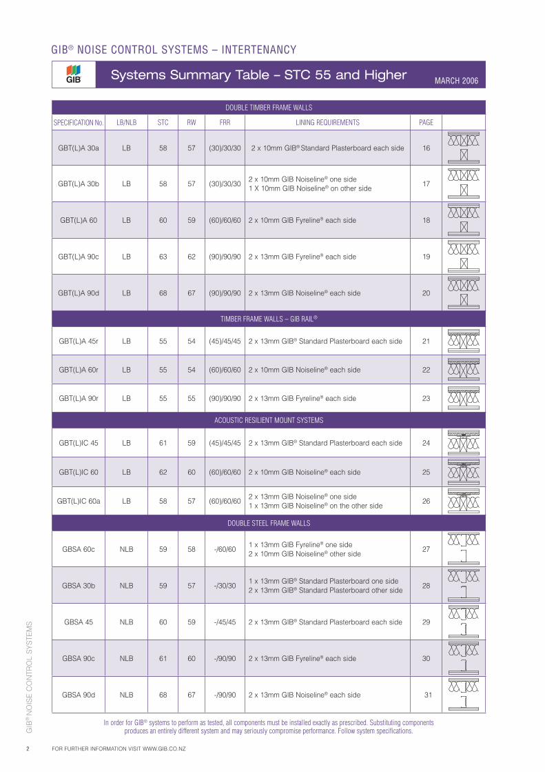
DOUBLE TIMBER FRAME WALLS
SPECIFICATION No. LB/NLB STC RW FRR LINING REQUIREMENTS PAGE
GBT(L)A 30a LB 58 57 (30)/30/30 2 x 10mm GIB® Standard Plasterboard each side 16
GBT(L)A 30b LB 58 57 (30)/30/302 x 10mm GIB Noiseline® one side1 X 10mm GIB Noiseline® on other side
17
GBT(L)A 60 LB 60 59 (60)/60/60 2 x 10mm GIB Fyreline® each side 18
GBT(L)A 90c LB 63 62 (90)/90/90 2 x 13mm GIB Fyreline® each side 19
GBT(L)A 90d LB 68 67 (90)/90/90 2 x 13mm GIB Noiseline® each side 20
TIMBER FRAME WALLS – GIB RAIL®
GBT(L)A 45r LB 55 54 (45)/45/45 2 x 13mm GIB® Standard Plasterboard each side 21
GBT(L)A 60r LB 55 54 (60)/60/60 2 x 10mm GIB Noiseline® each side 22
GBT(L)A 90r LB 55 55 (90)/90/90 2 x 13mm GIB Fyreline® each side 23
ACOUSTIC RESILIENT MOUNT SYSTEMS
GBT(L)IC 45 LB 61 59 (45)/45/45 2 x 13mm GIB® Standard Plasterboard each side 24
GBT(L)IC 60 LB 62 60 (60)/60/60 2 x 10mm GIB Noiseline® each side 25
GBT(L)IC 60a LB 58 57 (60)/60/602 x 13mm GIB Noiseline® one side1 x 13mm GIB Noiseline® on the other side
26
DOUBLE STEEL FRAME WALLS
GBSA 60c NLB 59 58 -/60/601 x 13mm GIB Fyreline® one side2 x 10mm GIB Noiseline® other side
27
GBSA 30b NLB 59 57 -/30/301 x 13mm GIB® Standard Plasterboard one side2 x 13mm GIB® Standard Plasterboard other side
28
GBSA 45 NLB 60 59 -/45/45 2 x 13mm GIB® Standard Plasterboard each side 29
GBSA 90c NLB 61 60 -/90/90 2 x 13mm GIB Fyreline® each side 30
GBSA 90d NLB 68 67 -/90/90 2 x 13mm GIB Noiseline® each side 31
In order for GIB® systems to perform as tested, all components must be installed exactly as prescribed. Substituting components
produces an entirely different system and may seriously compromise performance. Follow system specifications.
GIB
® N
OIS
E C
ON
TRO
L S
YS
TEM
S
3FOR FURTHER INFORMATION VISIT WWW.GIB.CO.NZ
GIB® NOISE CONTROL SYSTEMS – INTERTENANCY
Systems Summary Table – STC 55 and Higher MARCH 2006
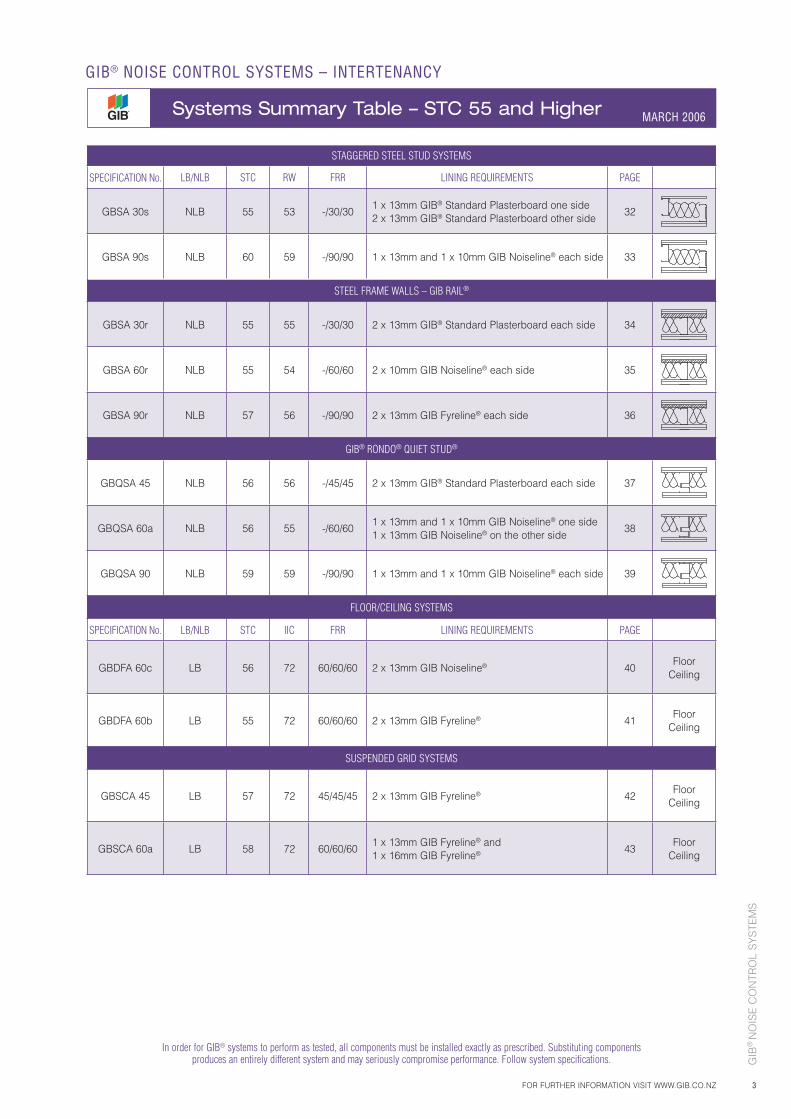
STAGGERED STEEL STUD SYSTEMS
SPECIFICATION No. LB/NLB STC RW FRR LINING REQUIREMENTS PAGE
GBSA 30s NLB 55 53 -/30/301 x 13mm GIB® Standard Plasterboard one side2 x 13mm GIB® Standard Plasterboard other side
32
GBSA 90s NLB 60 59 -/90/90 1 x 13mm and 1 x 10mm GIB Noiseline® each side 33
STEEL FRAME WALLS – GIB RAIL®
GBSA 30r NLB 55 55 -/30/30 2 x 13mm GIB® Standard Plasterboard each side 34
GBSA 60r NLB 55 54 -/60/60 2 x 10mm GIB Noiseline® each side 35
GBSA 90r NLB 57 56 -/90/90 2 x 13mm GIB Fyreline® each side 36
GIB® RONDO® QUIET STUD®
GBQSA 45 NLB 56 56 -/45/45 2 x 13mm GIB® Standard Plasterboard each side 37
GBQSA 60a NLB 56 55 -/60/601 x 13mm and 1 x 10mm GIB Noiseline® one side1 x 13mm GIB Noiseline® on the other side
38
GBQSA 90 NLB 59 59 -/90/90 1 x 13mm and 1 x 10mm GIB Noiseline® each side 39
FLOOR/CEILING SYSTEMS
SPECIFICATION No. LB/NLB STC IIC FRR LINING REQUIREMENTS PAGE
GBDFA 60c LB 56 72 60/60/60 2 x 13mm GIB Noiseline® 40Floor
Ceiling
GBDFA 60b LB 55 72 60/60/60 2 x 13mm GIB Fyreline® 41Floor
Ceiling
SUSPENDED GRID SYSTEMS
GBSCA 45 LB 57 72 45/45/45 2 x 13mm GIB Fyreline® 42Floor
Ceiling
GBSCA 60a LB 58 72 60/60/601 x 13mm GIB Fyreline® and 1 x 16mm GIB Fyreline® 43
FloorCeiling
In order for GIB® systems to perform as tested, all components must be installed exactly as prescribed. Substituting components produces an entirely different system and may seriously compromise performance. Follow system specifications.
GIB
® N
OIS
E C
ON
TRO
L S
YS
TEM
S
4
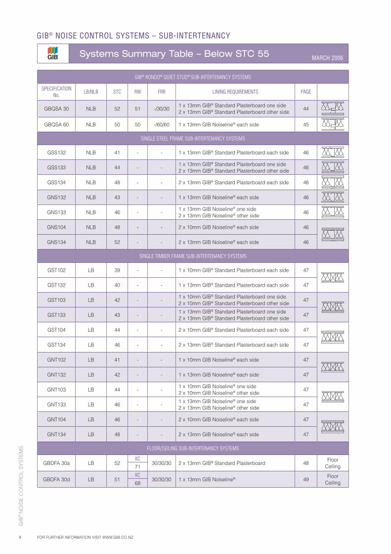
GIB® NOISE CONTROL SYSTEMS – SUB-INTERTENANCY
Systems Summary Table – Below STC 55 MARCH 2006
FOR FURTHER INFORMATION VISIT WWW.GIB.CO.NZ
GIB® RONDO® QUIET STUD® SUB-INTERTENANCY SYSTEMS
SPECIFICATIONNo.
LB/NLB STC RW FRR LINING REQUIREMENTS PAGE
GBQSA 30 NLB 52 51 -/30/301 x 13mm GIB® Standard Plasterboard one side2 x 13mm GIB® Standard Plasterboard other side
44
GBQSA 60 NLB 50 50 -/60/60 1 x 13mm GIB Noiseline® each side 45
SINGLE STEEL FRAME SUB-INTERTENANCY SYSTEMS
GSS132 NLB 41 - - 1 x 13mm GIB® Standard Plasterboard each side 46
GSS133 NLB 44 - -1 x 13mm GIB® Standard Plasterboard one side2 x 13mm GIB® Standard Plasterboard other side
46
GSS134 NLB 48 - - 2 x 13mm GIB® Standard Plasterboard each side 46
GNS132 NLB 43 - - 1 x 13mm GIB Noiseline® each side 46
GNS133 NLB 46 - -1 x 13mm GIB Noiseline® one side2 x 13mm GIB Noiseline® other side
46
GNS104 NLB 48 - - 2 x 10mm GIB Noiseline® each side 46
GNS134 NLB 52 - - 2 x 13mm GIB Noiseline® each side 46
SINGLE TIMBER FRAME SUB-INTERTENANCY SYSTEMS
GST102 LB 39 - - 1 x 10mm GIB® Standard Plasterboard each side 47
GST132 LB 40 - - 1 x 13mm GIB® Standard Plasterboard each side 47
GST103 LB 42 - -1 x 10mm GIB® Standard Plasterboard one side2 x 10mm GIB® Standard Plasterboard other side
47
GST133 LB 43 - -1 x 13mm GIB® Standard Plasterboard one side2 x 13mm GIB® Standard Plasterboard other side
47
GST104 LB 44 - - 2 x 10mm GIB® Standard Plasterboard each side 47
GST134 LB 46 - - 2 x 13mm GIB® Standard Plasterboard each side 47
GNT102 LB 41 - - 1 x 10mm GIB Noiseline® each side 47
GNT132 LB 42 - - 1 x 13mm GIB Noiseline® each side 47
GNT103 LB 44 - -1 x 10mm GIB Noiseline® one side2 x 10mm GIB Noiseline® other side
47
GNT133 LB 46 - -1 x 13mm GIB Noiseline® one side2 x 13mm GIB Noiseline® other side
47
GNT104 LB 46 - - 2 x 10mm GIB Noiseline® each side 47
GNT134 LB 48 - - 2 x 13mm GIB Noiseline® each side 47
FLOOR/CEILING SUB-INTERTENANCY SYSTEMS
GBDFA 30a LB 52IIC
30/30/30 2 x 13mm GIB® Standard Plasterboard 48Floor
Ceiling71
GBDFA 30d LB 51IIC
30/30/30 1 x 13mm GIB Noiseline® 49Floor
Ceiling68
GIB
® N
OIS
E C
ON
TRO
L S
YS
TEM
S
5
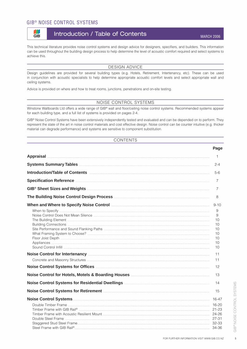
CONTENTS
Page
Appraisal ......................................................................................................................................................................................................................................................................................... 1
Systems Summary Tables .................................................................................................................................................................................................................................. 2-4
Introduction/Table of Contents ................................................................................................................................................................................................................ 5-6
Specifi cation Reference ........................................................................................................................................................................................................................................ 7
GIB® Sheet Sizes and Weights ..................................................................................................................................................................................................................... 7
The Building Noise Control Design Process ..................................................................................................................................................................... 8
When and Where to Specify Noise Control .......................................................................................................................................................................... 9-10
When to Specify .................................................................................................................................................................................................................................................................... 9 Noise Control Does Not Mean Silence ......................................................................................................................................................................................................... 9 The Building Element ...................................................................................................................................................................................................................................................... 10 Building Connections ...................................................................................................................................................................................................................................................... 10 Site Performance and Sound Flanking Paths ....................................................................................................................................................................................... 10 What Framing System to Choose? ................................................................................................................................................................................................................... 10 Floor Joist Depth .................................................................................................................................................................................................................................................................. 10 Appliances .................................................................................................................................................................................................................................................................................. 10 Sound Control Infill ............................................................................................................................................................................................................................................................. 10
Noise Control for Intertenancy .................................................................................................................................................................................................................. 11
Concrete and Masonry Structures .................................................................................................................................................................................................................... 11
Noise Control Systems for Offi ces ..................................................................................................................................................................................................... 12
Noise Control for Hotels, Motels & Boarding Houses ........................................................................................................................................ 13
Noise Control Systems for Residential Dwellings ................................................................................................................................................... 14
Noise Control Systems for Retirement ........................................................................................................................................................................................ 15
Noise Control Systems ............................................................................................................................................................................................................................................. 16-47
Double Timber Frame ..................................................................................................................................................................................................................................................... 16-20 Timber Frame with GIB Rail® .................................................................................................................................................................................................................................. 21-23 Timber Frame with Acoustic Resilient Mount ........................................................................................................................................................................................ 24-26 Double Steel Frame .......................................................................................................................................................................................................................................................... 27-31 Staggered Stud Steel Frame..................................................................................................................................................................................................................................... 32-33 Steel Frame with GIB Rail®.......................................................................................................................................................................................................................................... 34-36
This technical literature provides noise control systems and design advice for designers, specifiers, and builders. This information can be used throughout the building design process to help determine the level of acoustic comfort required and select systems to achieve this.
DESIGN ADVICEDesign guidelines are provided for several building types (e.g. Hotels, Retirement, Intertenancy, etc). These can be usedin conjunction with acoustic specialists to help determine appropriate acoustic comfort levels and select appropriate wall and ceiling systems.
Advice is provided on where and how to treat rooms, junctions, penetrations and on-site testing.
NOISE CONTROL SYSTEMSWinstone Wallboards Ltd offers a wide range of GIB® wall and floor/ceiling noise control systems. Recommended systems appear for each building type, and a full list of systems is provided on pages 2-4.
GIB® Noise Control Systems have been extensively independently tested and evaluated and can be depended on to perform. They represent the state of the art in noise control materials and cost effective design. Noise control can be counter intuitive (e.g. thicker material can degrade performance) and systems are sensitive to component substitution.
FOR FURTHER INFORMATION VISIT WWW.GIB.CO.NZ
GIB® NOISE CONTROL SYSTEMS
Introduction / Table of Contents MARCH 2006
GIB
® N
OIS
E C
ON
TRO
L S
YS
TEM
S
6
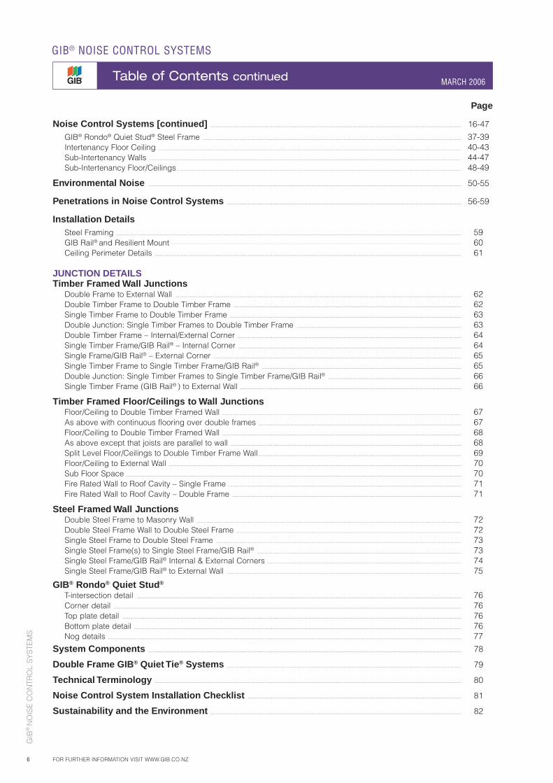
Page
Noise Control Systems [continued] .................................................................................................................................................................................................. 16-47
GIB® Rondo® Quiet Stud® Steel Frame ........................................................................................................................................................................................................ 37-39 Intertenancy Floor Ceiling .......................................................................................................................................................................................................................................... 40-43 Sub-Intertenancy Walls ................................................................................................................................................................................................................................................. 44-47 Sub-Intertenancy Floor/Ceilings ............................................................................................................................................................................................................................ 48-49
Environmental Noise .................................................................................................................................................................................................................................................. 50-55
Penetrations in Noise Control Systems ..................................................................................................................................................................................... 56-59
Installation Details Steel Framing ........................................................................................................................................................................................................................................................................... 59 GIB Rail® and Resilient Mount ................................................................................................................................................................................................................................................................................................................................................................................................... 60 Ceiling Perimeter Details ............................................................................................................................................................................................................................................. 61
JUNCTION DETAILSTimber Framed Wall Junctions Double Frame to External Wall ............................................................................................................................................................................................................................. 62 Double Timber Frame to Double Timber Frame ................................................................................................................................................................................ 62 Single Timber Frame to Double Timber Frame ................................................................................................................................................................................... 63 Double Junction: Single Timber Frames to Double Timber Frame ............................................................................................................................... 63 Double Timber Frame – Internal/External Corner ............................................................................................................................................................................. 64 Single Timber Frame/GIB Rail® – Internal Corner ............................................................................................................................................................................ 64 Single Frame/GIB Rail® – External Corner ................................................................................................................................................................................................ 65 Single Timber Frame to Single Timber Frame/GIB Rail® .......................................................................................................................................................... 65 Double Junction: Single Timber Frames to Single Timber Frame/GIB Rail® ....................................................................................................... 66 Single Timber Frame (GIB Rail® ) to External Wall ........................................................................................................................................................................... 66
Timber Framed Floor/Ceilings to Wall Junctions Floor/Ceiling to Double Timber Framed Wall ......................................................................................................................................................................................... 67 As above with continuous flooring over double frames ............................................................................................................................................................. 67 Floor/Ceiling to Double Timber Framed Wall ......................................................................................................................................................................................... 68 As above except that joists are parallel to wall .................................................................................................................................................................................. 68 Split Level Floor/Ceilings to Double Timber Frame Wall ............................................................................................................................................................. 69 Floor/Ceiling to External Wall .................................................................................................................................................................................................................................. 70 Sub Floor Space ................................................................................................................................................................................................................................................................... 70 Fire Rated Wall to Roof Cavity – Single Frame .................................................................................................................................................................................... 71 Fire Rated Wall to Roof Cavity – Double Frame ................................................................................................................................................................................. 71
Steel Framed Wall Junctions Double Steel Frame to Masonry Wall ............................................................................................................................................................................................................. 72 Double Steel Frame Wall to Double Steel Frame .............................................................................................................................................................................. 72 Single Steel Frame to Double Steel Frame .............................................................................................................................................................................................. 73 Single Steel Frame(s) to Single Steel Frame/GIB Rail® .............................................................................................................................................................. 73 Single Steel Frame/GIB Rail® Internal & External Corners ...................................................................................................................................................... 74 Single Steel Frame/GIB Rail® to External Wall ..................................................................................................................................................................................... 75
GIB® Rondo® Quiet Stud®
T-intersection detail ........................................................................................................................................................................................................................................................... 76 Corner detail ............................................................................................................................................................................................................................................................................. 76 Top plate detail ...................................................................................................................................................................................................................................................................... 76 Bottom plate detail ............................................................................................................................................................................................................................................................. 76 Nog details ................................................................................................................................................................................................................................................................................. 77
System Components .................................................................................................................................................................................................................................................. 78
Double Frame GIB® Quiet Tie® Systems ..................................................................................................................................................................................... 79
Technical Terminology ............................................................................................................................................................................................................................................. 80
Noise Control System Installation Checklist ..................................................................................................................................................................... 81
Sustainability and the Environment .................................................................................................................................................................................................. 82
GIB® NOISE CONTROL SYSTEMS
Table of Contents continued MARCH 2006
FOR FURTHER INFORMATION VISIT WWW.GIB.CO.NZ
GIB
® N
OIS
E C
ON
TRO
L S
YS
TEM
S
7
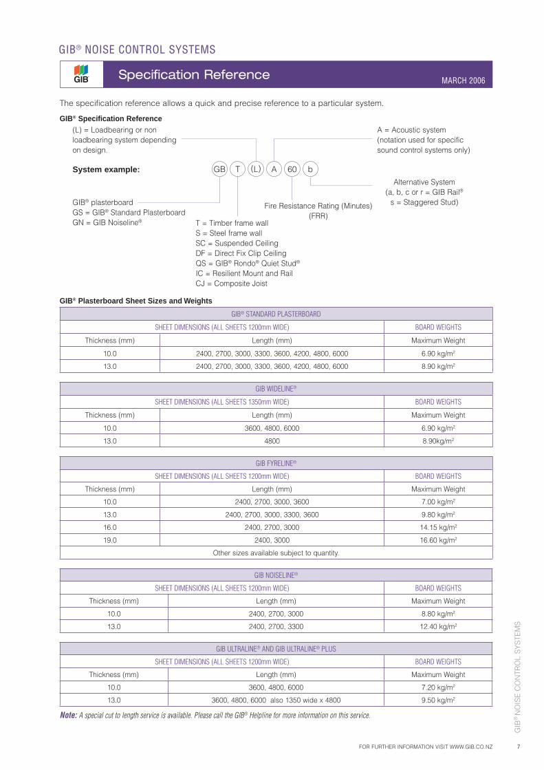
GIB® Plasterboard Sheet Sizes and Weights
GIB® STANDARD PLASTERBOARD
SHEET DIMENSIONS (ALL SHEETS 1200mm WIDE) BOARD WEIGHTS
Thickness (mm) Length (mm) Maximum Weight
10.0 2400, 2700, 3000, 3300, 3600, 4200, 4800, 6000 6.90 kg/m2
13.0 2400, 2700, 3000, 3300, 3600, 4200, 4800, 6000 8.90 kg/m2
GIB WIDELINE®
SHEET DIMENSIONS (ALL SHEETS 1350mm WIDE) BOARD WEIGHTS
Thickness (mm) Length (mm) Maximum Weight
10.0 3600, 4800, 6000 6.90 kg/m2
13.0 4800 8.90kg/m2
GIB FYRELINE®
SHEET DIMENSIONS (ALL SHEETS 1200mm WIDE) BOARD WEIGHTS
Thickness (mm) Length (mm) Maximum Weight
10.0 2400, 2700, 3000, 3600 7.00 kg/m2
13.0 2400, 2700, 3000, 3300, 3600 9.80 kg/m2
16.0 2400, 2700, 3000 14.15 kg/m2
19.0 2400, 3000 16.60 kg/m2
Other sizes available subject to quantity.
GIB NOISELINE®
SHEET DIMENSIONS (ALL SHEETS 1200mm WIDE) BOARD WEIGHTS
Thickness (mm) Length (mm) Maximum Weight
10.0 2400, 2700, 3000 8.80 kg/m2
13.0 2400, 2700, 3300 12.40 kg/m2
GIB ULTRALINE® AND GIB ULTRALINE® PLUS
SHEET DIMENSIONS (ALL SHEETS 1200mm WIDE) BOARD WEIGHTS
Thickness (mm) Length (mm) Maximum Weight
10.0 3600, 4800, 6000 7.20 kg/m2
13.0 3600, 4800, 6000 also 1350 wide x 4800 9.50 kg/m2
Note: A special cut to length service is available. Please call the GIB® Helpline for more information on this service.
(L) = Loadbearing or non loadbearing system depending on design.
System example:
GIB® plasterboardGS = GIB® Standard PlasterboardGN = GIB Noiseline®
Fire Resistance Rating (Minutes)(FRR)
Alternative System(a, b, c or r = GIB Rail®
s = Staggered Stud)
T = Timber frame wallS = Steel frame wallSC = Suspended CeilingDF = Direct Fix Clip CeilingQS = GIB® Rondo® Quiet Stud®
IC = Resilient Mount and RailCJ = Composite Joist
A = Acoustic system (notation used for specific sound control systems only)
GB T (L) A 60 b
FOR FURTHER INFORMATION VISIT WWW.GIB.CO.NZ
GIB® NOISE CONTROL SYSTEMS
Specification Reference MARCH 2006
The specification reference allows a quick and precise reference to a particular system.
GIB® Specification Reference
GIB
® N
OIS
E C
ON
TRO
L S
YS
TEM
S
8
GIB® NOISE CONTROL SYSTEMS
The Building Noise Control Design Process MARCH 2006
FOR FURTHER INFORMATION VISIT WWW.GIB.CO.NZ
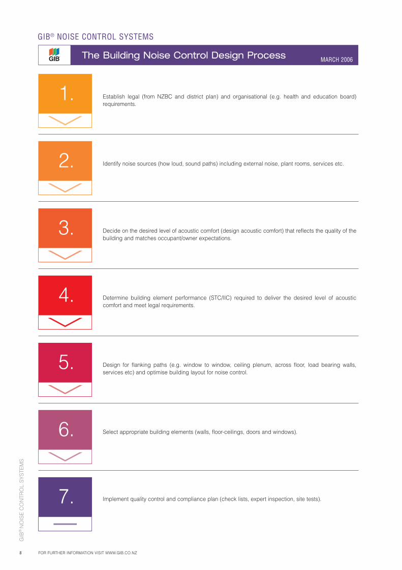
Establish legal (from NZBC and district plan) and organisational (e.g. health and education board) requirements.
Identify noise sources (how loud, sound paths) including external noise, plant rooms, services etc.
Decide on the desired level of acoustic comfort (design acoustic comfort) that reflects the quality of the building and matches occupant/owner expectations.
Determine building element performance (STC/IIC) required to deliver the desired level of acoustic comfort and meet legal requirements.
Design for flanking paths (e.g. window to window, ceiling plenum, across floor, load bearing walls, services etc) and optimise building layout for noise control.
Select appropriate building elements (walls, floor-ceilings, doors and windows).
Implement quality control and compliance plan (check lists, expert inspection, site tests).
1.
2.
3.
4.
5.
6.
7.
GIB
® N
OIS
E C
ON
TRO
L S
YS
TEM
S
9FOR FURTHER INFORMATION VISIT WWW.GIB.CO.NZ
GIB® NOISE CONTROL SYSTEMS
When and Where to Specify Noise Control MARCH 2006
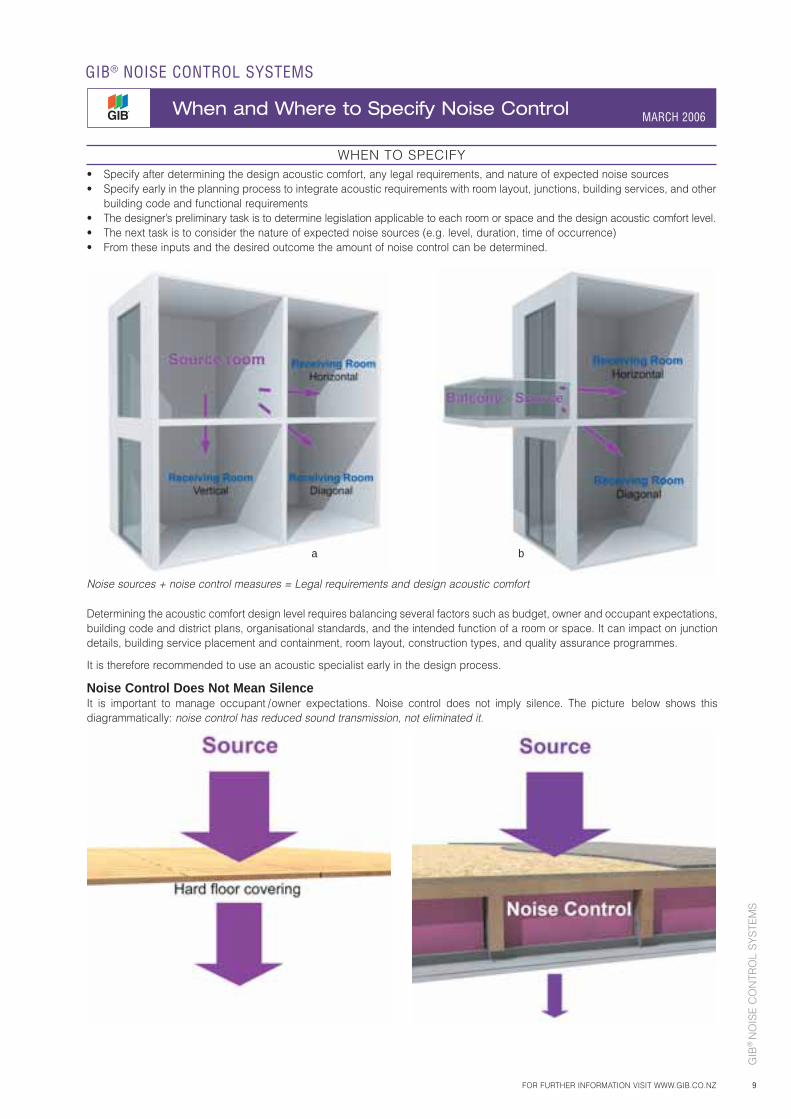
WHEN TO SPECIFY• Specify after determining the design acoustic comfort, any legal requirements, and nature of expected noise sources• Specify early in the planning process to integrate acoustic requirements with room layout, junctions, building services, and other
building code and functional requirements• The designer’s preliminary task is to determine legislation applicable to each room or space and the design acoustic comfort level.• The next task is to consider the nature of expected noise sources (e.g. level, duration, time of occurrence)• From these inputs and the desired outcome the amount of noise control can be determined.
Noise sources + noise control measures = Legal requirements and design acoustic comfort
Determining the acoustic comfort design level requires balancing several factors such as budget, owner and occupant expectations, building code and district plans, organisational standards, and the intended function of a room or space. It can impact on junction details, building service placement and containment, room layout, construction types, and quality assurance programmes.
It is therefore recommended to use an acoustic specialist early in the design process.
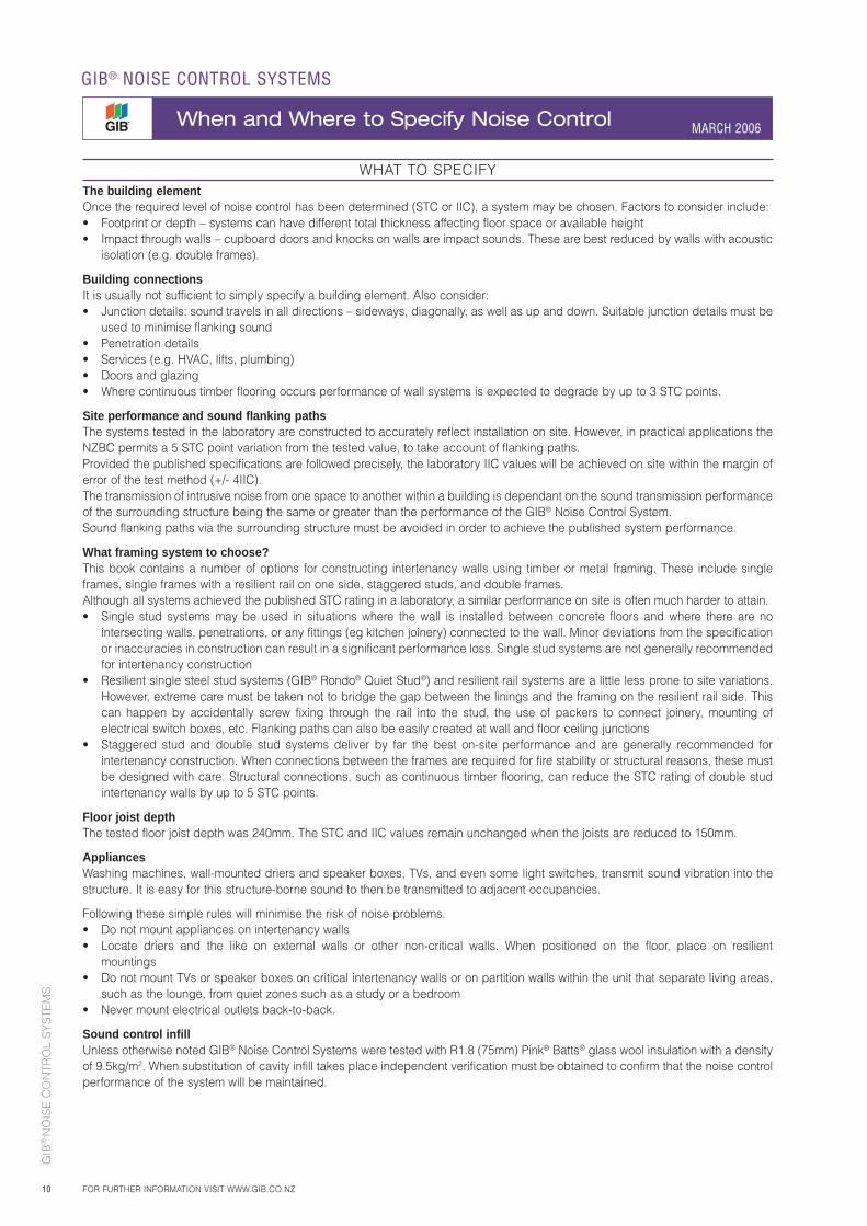
Noise Control Does Not Mean SilenceIt is important to manage occupant / owner expectations. Noise control does not imply silence. The picture below shows this diagrammatically: noise control has reduced sound transmission, not eliminated it.
a b
GIB
® N
OIS
E C
ON
TRO
L S
YS
TEM
S
10
GIB® NOISE CONTROL SYSTEMS
When and Where to Specify Noise Control MARCH 2006
FOR FURTHER INFORMATION VISIT WWW.GIB.CO.NZ
WHAT TO SPECIFYThe building elementOnce the required level of noise control has been determined (STC or IIC), a system may be chosen. Factors to consider include:• Footprint or depth – systems can have different total thickness affecting floor space or available height• Impact through walls – cupboard doors and knocks on walls are impact sounds. These are best reduced by walls with acoustic
isolation (e.g. double frames).
Building connectionsIt is usually not sufficient to simply specify a building element. Also consider:• Junction details: sound travels in all directions – sideways, diagonally, as well as up and down. Suitable junction details must be
used to minimise flanking sound• Penetration details• Services (e.g. HVAC, lifts, plumbing)• Doors and glazing• Where continuous timber flooring occurs performance of wall systems is expected to degrade by up to 3 STC points.
Site performance and sound flanking pathsThe systems tested in the laboratory are constructed to accurately reflect installation on site. However, in practical applications the NZBC permits a 5 STC point variation from the tested value, to take account of flanking paths.Provided the published specifications are followed precisely, the laboratory IIC values will be achieved on site within the margin of error of the test method (+/- 4IIC).The transmission of intrusive noise from one space to another within a building is dependant on the sound transmission performance of the surrounding structure being the same or greater than the performance of the GIB® Noise Control System.Sound flanking paths via the surrounding structure must be avoided in order to achieve the published system performance.
What framing system to choose?This book contains a number of options for constructing intertenancy walls using timber or metal framing. These include single frames, single frames with a resilient rail on one side, staggered studs, and double frames.Although all systems achieved the published STC rating in a laboratory, a similar performance on site is often much harder to attain.• Single stud systems may be used in situations where the wall is installed between concrete floors and where there are no
intersecting walls, penetrations, or any fittings (eg kitchen joinery) connected to the wall. Minor deviations from the specification or inaccuracies in construction can result in a significant performance loss. Single stud systems are not generally recommended for intertenancy construction
• Resilient single steel stud systems (GIB® Rondo® Quiet Stud®) and resilient rail systems are a little less prone to site variations. However, extreme care must be taken not to bridge the gap between the linings and the framing on the resilient rail side. This can happen by accidentally screw fixing through the rail into the stud, the use of packers to connect joinery, mounting of electrical switch boxes, etc. Flanking paths can also be easily created at wall and floor ceiling junctions
• Staggered stud and double stud systems deliver by far the best on-site performance and are generally recommended for intertenancy construction. When connections between the frames are required for fire stability or structural reasons, these must be designed with care. Structural connections, such as continuous timber flooring, can reduce the STC rating of double stud intertenancy walls by up to 5 STC points.
Floor joist depthThe tested floor joist depth was 240mm. The STC and IIC values remain unchanged when the joists are reduced to 150mm.
AppliancesWashing machines, wall-mounted driers and speaker boxes, TVs, and even some light switches, transmit sound vibration into the structure. It is easy for this structure-borne sound to then be transmitted to adjacent occupancies.
Following these simple rules will minimise the risk of noise problems.• Do not mount appliances on intertenancy walls• Locate driers and the like on external walls or other non-critical walls. When positioned on the floor, place on resilient
mountings• Do not mount TVs or speaker boxes on critical intertenancy walls or on partition walls within the unit that separate living areas,
such as the lounge, from quiet zones such as a study or a bedroom• Never mount electrical outlets back-to-back.
Sound control infillUnless otherwise noted GIB® Noise Control Systems were tested with R1.8 (75mm) Pink® Batts® glass wool insulation with a density of 9.5kg/m2. When substitution of cavity infill takes place independent verification must be obtained to confirm that the noise control performance of the system will be maintained.
GIB
® N
OIS
E C
ON
TRO
L S
YS
TEM
S
11
MARCH 2006
FOR FURTHER INFORMATION VISIT WWW.GIB.CO.NZ
GIB® NOISE CONTROL SYSTEMS
Noise Control for Intertenancy MARCH 2006
INTRODUCTIONWhere separate occupancies adjoin, noise is a fundamental consideration. Designers need to select an acoustic comfort level aligned with occupant expectations. Besides impacting the sense of quality, noise control reduces annoyance from neighbours and improves the sense of privacy.Hence, while the New Zealand Building Code (NZBC) sets a legal minimum, it is common to set higher standards as a point of differentiation and to align with the quality of the building.
REGULATIONSThe NZBC (Clause G6) sets a legal minimum noise control performance between adjoining occupancies. The code provides a minimum level of noise protection for occupants. Occupants often have higher expectations. While guaranteed silence between adjoining units is not possible, it is possible to considerably improve on the provisions of the NZBC.
SETTING THE DESIGN ACOUSTIC COMFORT LEVELAn important design question is which level of acoustic comfort should be considered. The table below links comfort to STC and IIC ratings. The table provides a guide to choose GIB® Noise Control Systems that best meet your needs for that level of comfort.The information is derived from European studies and standards and is provided for general guidance.
ACOUSTIC COMFORT RATING COMMENT
Minimum:50% of occupants satisfied
STC 55 / FSTC 50 IIC 55 / FIIC 50 This is the NZBC minimum requirement.
Satisfaction:About 80% of occupants satisfied
STC 60 / FSTC 55IIC 60 / FIIC 55 dB(A) 30 in living areas
It is necessary to identify and consider all potential sound sources e.g. services and external noise. Typically these are designed for in terms of the sound level in living areas, in dB(A).
Superior performance: sometimes disturbed by noise
STC 65 / FSTC 60IIC 65 / FIIC 60
At higher comfort levels the ability of a construction to reduce low frequency sounds, for example home theatre and loud music is particularly important.
Excellent:Seldom disturbed by noise
STC 65+/ FSTC 65IIC 65+ / FIIC 65 dB(A) 20 in living areas Consideration of low frequency performance
FLOOR/CEILING SYSTEMSGIB® Noise Control floor-ceiling systems offer excellent performance for both airborne and impact sound. However, although code compliance can be easily achieved with good quality underlay beneath carpet, code compliance for impact sound is much more difficult to achieve on hard floor surfaces.
GIB® Noise Control systems for hard floor surfaces such as timber strip flooring, vinyl and ceramic tiles are available with the inclusion of GIB Sound Barrier® floor overlay. These systems are published in the technical brochure entitled “GIB Sound Barrier®”.
Although there appears little difference in performance between some floor-ceiling systems published in this book, the use of GIB Quiet Clip® in systems GBDFA 60c, GBDFA 30a and GBDFA 30d offers superior low frequency performance of up to 8 dB improved attenuation in the frequency range 50Hz to 125Hz. As footfall, and other common domestic sound is often in this range the GIB Quiet Clip® offers significant advantage over direct fix systems.
MINIMISE RISKA quality control programme is recommended to help minimise risk from variations, and to indicate noise control performance early on. Liaise with local authorities to determine the requirements for compliance (e.g. acoustic engineers approval, lab test certificate, or a specific set of onsite tests). The NZBC Clause G6 requires that habitable spaces in household units are protected from other occupancies using wall and floor/ceiling elements with a laboratory tested performance of STC 55 (walls and floors) and IIC 55 (floors only).
CONCRETE AND MASONRY STRUCTURESThe performance of pre-cast concrete walls more than 150mm thick and solid filled masonry 200mm thick is very sensitive to construction practices, detailing and concrete density. Although these walls can achieve STC 55, the sound attenuation is greatly enhanced when resilient mounts and/or battens are installed on at least one side. These additions can be counter intuitive unless a minimum cavity of 45mm is created and filled with sound control infill prior to lining. Polystyrene is not a suitable infill. For further assistance with noise control ratings for concrete and masonry structures please call the GIB® Helpline 0800 100 442.
GIB
® N
OIS
E C
ON
TRO
L S
YS
TEM
S
12
GIB® NOISE CONTROL SYSTEMS
Noise Control Systems for Offices MARCH 2006
FOR FURTHER INFORMATION VISIT WWW.GIB.CO.NZ
INTRODUCTIONNoise control plays an important role in office comfort, productivity and privacy/confidentiality. Studies show that a positive environment has a positive effect on business. Attention needs to be given to noise control, room acoustics, and services.
Open plan offices require a degree of privacy which is achieved to some extent by masking sounds.
Senior managers expect more noise control and require it for confidentiality. Seminar and meeting rooms, and walls between tenants need to protect the amenity value of users. Wall penetrating ceilings will provide a higher level of performance.
The table below summarises general noise control recommendations for offices.
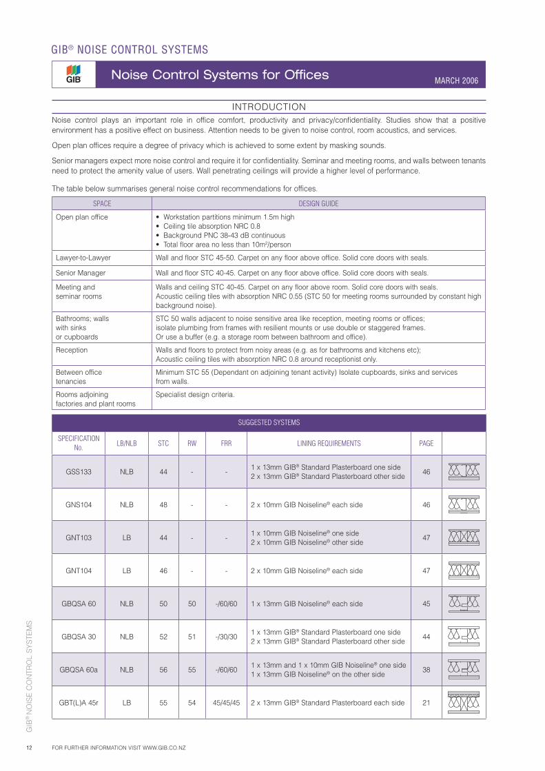
SPACE DESIGN GUIDE
Open plan office • Workstation partitions minimum 1.5m high• Ceiling tile absorption NRC 0.8• Background PNC 38-43 dB continuous• Total floor area no less than 10m2/person
Lawyer-to-Lawyer Wall and floor STC 45-50. Carpet on any floor above office. Solid core doors with seals.
Senior Manager Wall and floor STC 40-45. Carpet on any floor above office. Solid core doors with seals.
Meeting and seminar rooms
Walls and ceiling STC 40-45. Carpet on any floor above room. Solid core doors with seals. Acoustic ceiling tiles with absorption NRC 0.55 (STC 50 for meeting rooms surrounded by constant high background noise).
Bathrooms; walls with sinks or cupboards
STC 50 walls adjacent to noise sensitive area like reception, meeting rooms or offices; isolate plumbing from frames with resilient mounts or use double or staggered frames. Or use a buffer (e.g. a storage room between bathroom and office).
Reception Walls and floors to protect from noisy areas (e.g. as for bathrooms and kitchens etc); Acoustic ceiling tiles with absorption NRC 0.8 around receptionist only.
Between office tenancies
Minimum STC 55 (Dependant on adjoining tenant activity) Isolate cupboards, sinks and services from walls.
Rooms adjoining factories and plant rooms
Specialist design criteria.
SUGGESTED SYSTEMS
SPECIFICATIONNo. LB/NLB STC RW FRR LINING REQUIREMENTS PAGE
GSS133 NLB 44 - -1 x 13mm GIB® Standard Plasterboard one side2 x 13mm GIB® Standard Plasterboard other side
46
GNS104 NLB 48 - - 2 x 10mm GIB Noiseline® each side 46
GNT103 LB 44 - -1 x 10mm GIB Noiseline® one side2 x 10mm GIB Noiseline® other side
47
GNT104 LB 46 - - 2 x 10mm GIB Noiseline® each side 47
GBQSA 60 NLB 50 50 -/60/60 1 x 13mm GIB Noiseline® each side 45
GBQSA 30 NLB 52 51 -/30/301 x 13mm GIB® Standard Plasterboard one side2 x 13mm GIB® Standard Plasterboard other side
44
GBQSA 60a NLB 56 55 -/60/601 x 13mm and 1 x 10mm GIB Noiseline® one side1 x 13mm GIB Noiseline® on the other side
38
GBT(L)A 45r LB 55 54 45/45/45 2 x 13mm GIB® Standard Plasterboard each side 21
GIB
® N
OIS
E C
ON
TRO
L S
YS
TEM
S
13FOR FURTHER INFORMATION VISIT WWW.GIB.CO.NZ
GIB® NOISE CONTROL SYSTEMS
Noise Control for Hotels, Motels & Boarding Houses MARCH 2006
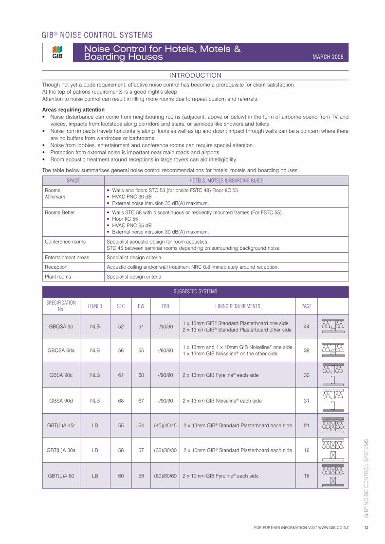
INTRODUCTIONThough not yet a code requirement, effective noise control has become a prerequisite for client satisfaction.At the top of patrons requirements is a good night’s sleep. Attention to noise control can result in filling more rooms due to repeat custom and referrals.
Areas requiring attention• Noise disturbance can come from neighbouring rooms (adjacent, above or below) in the form of airborne sound from TV and
voices, impacts from footsteps along corridors and stairs, or services like showers and toilets• Noise from impacts travels horizontally along floors as well as up and down; impact through walls can be a concern where there
are no buffers from wardrobes or bathrooms• Noise from lobbies, entertainment and conference rooms can require special attention• Protection from external noise is important near main roads and airports• Room acoustic treatment around receptions in large foyers can aid intelligibility.
The table below summarises general noise control recommendations for hotels, motels and boarding houses.
SPACE HOTELS, MOTELS & BOARDING GUIDE
Rooms Minimum
• Walls and floors STC 53 (for onsite FSTC 48) Floor IIC 55• HVAC PNC 30 dB• External noise intrusion 35 dB(A) maximum.
Rooms Better • Walls STC 58 with discontinuous or resiliently mounted frames (For FSTC 55)• Floor IIC 55• HVAC PNC 25 dB• External noise intrusion 30 dB(A) maximum.
Conference rooms Specialist acoustic design for room acoustics.STC 45 between seminar rooms depending on surrounding background noise.
Entertainment areas Specialist design criteria.
Reception Acoustic ceiling and/or wall treatment NRC 0.8 immediately around reception.
Plant rooms Specialist design criteria.
SUGGESTED SYSTEMS
SPECIFICATIONNo. LB/NLB STC RW FRR LINING REQUIREMENTS PAGE
GBQSA 30 NLB 52 51 -/30/301 x 13mm GIB® Standard Plasterboard one side2 x 13mm GIB® Standard Plasterboard other side
44
GBQSA 60a NLB 56 55 -/60/601 x 13mm and 1 x 10mm GIB Noiseline® one side1 x 13mm GIB Noiseline® on the other side
38
GBSA 90c NLB 61 60 -/90/90 2 x 13mm GIB Fyreline® each side 30
GBSA 90d NLB 68 67 -/90/90 2 x 13mm GIB Noiseline® each side 31
GBT(L)A 45r LB 55 54 (45)/45/45 2 x 13mm GIB® Standard Plasterboard each side 21
GBT(L)A 30a LB 58 57 (30)/30/30 2 x 10mm GIB® Standard Plasterboard each side 16
GBT(L)A 60 LB 60 59 (60)/60/60 2 x 10mm GIB Fyreline® each side 18
GIB
® N
OIS
E C
ON
TRO
L S
YS
TEM
S
14
GIB® NOISE CONTROL SYSTEMS
Noise Control Systems for Residential Dwellings MARCH 2006
FOR FURTHER INFORMATION VISIT WWW.GIB.CO.NZ
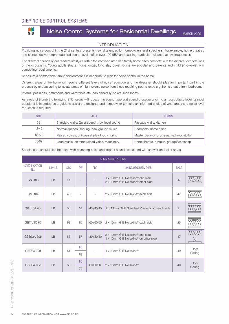
INTRODUCTIONProviding noise control in the 21st century presents new challenges for homeowners and specifiers. For example, home theatres and stereos deliver unprecedented sound levels, often over 100 dBA and causing particular nuisance at low frequencies.
The different sounds of our modern lifestyles within the confined area of a family home often compete with the different expectations of the occupants. Young adults stay at home longer, long stay guest rooms are popular and parents and children co-exist with competing requirements.
To ensure a comfortable family environment it is important to plan for noise control in the home.
Different areas of the home will require different levels of noise reduction and the designer should play an important part in the process by endeavouring to isolate areas of high volume noise from those requiring near silence e.g. home theatre from bedrooms.
Internal passages, bathrooms and wardrobes etc, can generally isolate such rooms.
As a rule of thumb the following STC values will reduce the sound type and sound pressure given to an acceptable level for most people. It is intended as a guide to assist the designer and homeowner to make an informed choice of what areas and noise level reduction is required.
STC NOISE ROOMS
35 Standard walls: Quiet speech, low level sound Passage walls, kitchen
42-45 Normal speech, snoring, background music Bedrooms, home offi ce
48-52 Raised voices, children at play, loud snoring Master bedroom, rumpus, bathroom/toilet
55-62 Loud music, extreme raised voice, machinery Home theatre, rumpus, garage/workshop
Special care should also be taken with plumbing noise and impact sound associated with shower and toilet areas.
SUGGESTED SYSTEMS
SPECIFICATION No. LB/NLB STC RW FRR LINING REQUIREMENTS PAGE
GNT103 LB 44 - -1 x 10mm GIB Noiseline® one side2 x 10mm GIB Noiseline® other side
47
GNT104 LB 46 - - 2 x 10mm GIB Noiseline® each side 47
GBT(L)A 45r LB 55 54 (45)/45/45 2 x 13mm GIB® Standard Plasterboard each side 21
GBT(L)IC 60 LB 62 60 (60)/60/60 2 x 10mm GIB Noiseline® each side 25
GBT(L)A 30b LB 58 57 (30)/30/302 x 10mm GIB Noiseline® one side1 x 10mm GIB Noiseline® on other side
17
GBDFA 30d LB 51IIC
- 1 x 13mm GIB Noiseline® 49Floor
Ceiling68
GBDFA 60c LB 56IIC
60/60/60 2 x 13mm GIB Noiseline® 40Floor
Ceiling72
GIB
® N
OIS
E C
ON
TRO
L S
YS
TEM
S
15
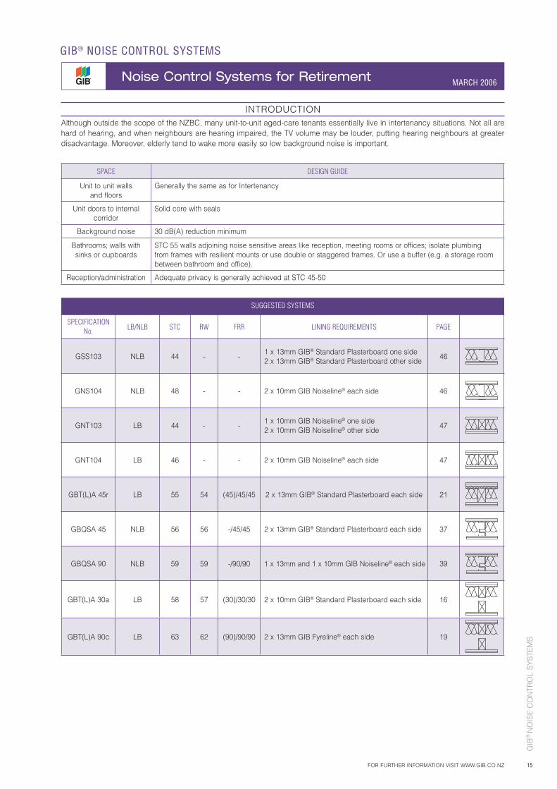
INTRODUCTIONAlthough outside the scope of the NZBC, many unit-to-unit aged-care tenants essentially live in intertenancy situations. Not all are hard of hearing, and when neighbours are hearing impaired, the TV volume may be louder, putting hearing neighbours at greater disadvantage. Moreover, elderly tend to wake more easily so low background noise is important.
SPACE DESIGN GUIDE
Unit to unit walls and floors
Generally the same as for Intertenancy
Unit doors to internal corridor
Solid core with seals
Background noise 30 dB(A) reduction minimum
Bathrooms; walls with sinks or cupboards
STC 55 walls adjoining noise sensitive areas like reception, meeting rooms or offices; isolate plumbing from frames with resilient mounts or use double or staggered frames. Or use a buffer (e.g. a storage room between bathroom and office).
Reception/administration Adequate privacy is generally achieved at STC 45-50
SUGGESTED SYSTEMS
SPECIFICATIONNo. LB/NLB STC RW FRR LINING REQUIREMENTS PAGE
GSS103 NLB 44 - -1 x 13mm GIB® Standard Plasterboard one side2 x 13mm GIB® Standard Plasterboard other side
46
GNS104 NLB 48 - - 2 x 10mm GIB Noiseline® each side 46
GNT103 LB 44 - -1 x 10mm GIB Noiseline® one side2 x 10mm GIB Noiseline® other side
47
GNT104 LB 46 - - 2 x 10mm GIB Noiseline® each side 47
GBT(L)A 45r LB 55 54 (45)/45/45 2 x 13mm GIB® Standard Plasterboard each side 21
GBQSA 45 NLB 56 56 -/45/45 2 x 13mm GIB® Standard Plasterboard each side 37
GBQSA 90 NLB 59 59 -/90/90 1 x 13mm and 1 x 10mm GIB Noiseline® each side 39
GBT(L)A 30a LB 58 57 (30)/30/30 2 x 10mm GIB® Standard Plasterboard each side 16
GBT(L)A 90c LB 63 62 (90)/90/90 2 x 13mm GIB Fyreline® each side 19
FOR FURTHER INFORMATION VISIT WWW.GIB.CO.NZ
GIB® NOISE CONTROL SYSTEMS
Noise Control Systems for Retirement MARCH 2006
GIB
® N
OIS
E C
ON
TRO
L S
YS
TEM
S
16
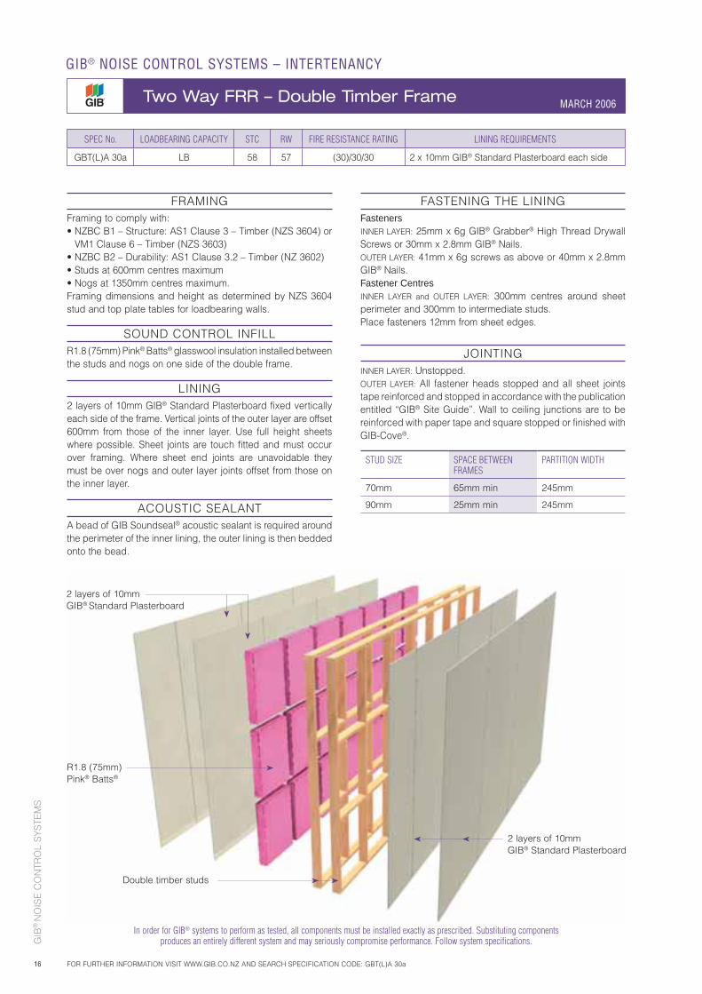
2 layers of 10mm GIB® Standard Plasterboard
R1.8 (75mm) Pink® Batts®
Double timber studs
SPEC No. LOADBEARING CAPACITY STC RW FIRE RESISTANCE RATING LINING REQUIREMENTS
GBT(L)A 30a LB 58 57 (30)/30/30 2 x 10mm GIB® Standard Plasterboard each side
FRAMINGFraming to comply with:• NZBC B1 – Structure: AS1 Clause 3 – Timber (NZS 3604) or
VM1 Clause 6 – Timber (NZS 3603)• NZBC B2 – Durability: AS1 Clause 3.2 – Timber (NZ 3602) • Studs at 600mm centres maximum• Nogs at 1350mm centres maximum.Framing dimensions and height as determined by NZS 3604 stud and top plate tables for loadbearing walls.
SOUND CONTROL INFILLR1.8 (75mm) Pink® Batts® glasswool insulation installed between the studs and nogs on one side of the double frame.
LINING2 layers of 10mm GIB® Standard Plasterboard fixed vertically each side of the frame. Vertical joints of the outer layer are offset 600mm from those of the inner layer. Use full height sheets where possible. Sheet joints are touch fitted and must occur over framing. Where sheet end joints are unavoidable they must be over nogs and outer layer joints offset from those on the inner layer.
ACOUSTIC SEALANTA bead of GIB Soundseal® acoustic sealant is required around the perimeter of the inner lining, the outer lining is then bedded onto the bead.
FASTENING THE LININGFastenersINNER LAYER: 25mm x 6g GIB® Grabber® High Thread Drywall Screws or 30mm x 2.8mm GIB® Nails.OUTER LAYER: 41mm x 6g screws as above or 40mm x 2.8mm GIB® Nails.Fastener CentresINNER LAYER and OUTER LAYER: 300mm centres around sheet perimeter and 300mm to intermediate studs. Place fasteners 12mm from sheet edges.
JOINTINGINNER LAYER: Unstopped.OUTER LAYER: All fastener heads stopped and all sheet joints tape reinforced and stopped in accordance with the publication entitled “GIB® Site Guide”. Wall to ceiling junctions are to be reinforced with paper tape and square stopped or finished with GIB-Cove®.
STUD SIZE SPACE BETWEEN FRAMES
PARTITION WIDTH
70mm 65mm min 245mm
90mm 25mm min 245mm
2 layers of 10mm GIB® Standard Plasterboard
GIB® NOISE CONTROL SYSTEMS – INTERTENANCY
Two Way FRR – Double Timber Frame MARCH 2006
FOR FURTHER INFORMATION VISIT WWW.GIB.CO.NZ AND SEARCH SPECIFICATION CODE: GBT(L)A 30a
In order for GIB® systems to perform as tested, all components must be installed exactly as prescribed. Substituting components produces an entirely different system and may seriously compromise performance. Follow system specifications.
GIB
® N
OIS
E C
ON
TRO
L S
YS
TEM
S
17
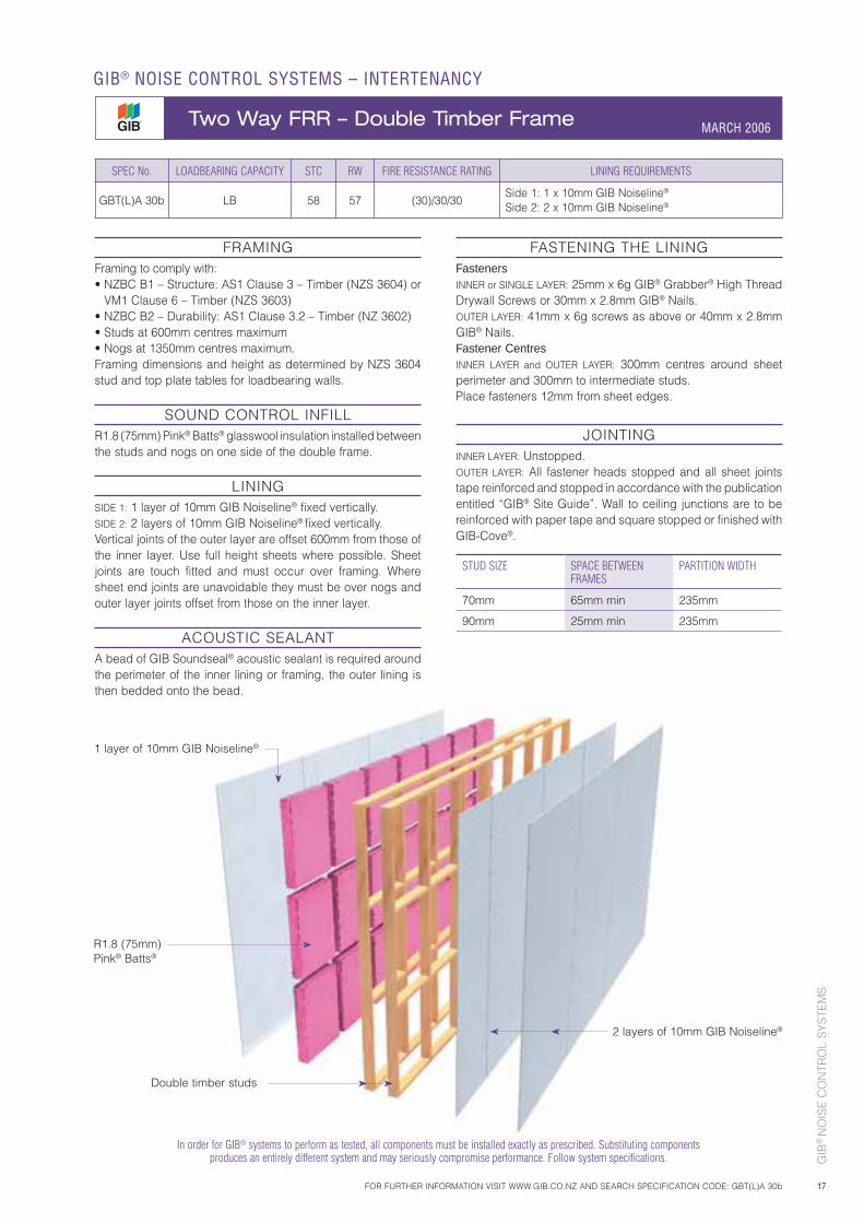
1 layer of 10mm GIB Noiseline®
R1.8 (75mm) Pink® Batts®
2 layers of 10mm GIB Noiseline®
Double timber studs
SPEC No. LOADBEARING CAPACITY STC RW FIRE RESISTANCE RATING LINING REQUIREMENTS
GBT(L)A 30b LB 58 57 (30)/30/30Side 1: 1 x 10mm GIB Noiseline®
Side 2: 2 x 10mm GIB Noiseline®
FRAMINGFraming to comply with: • NZBC B1 – Structure: AS1 Clause 3 – Timber (NZS 3604) or
VM1 Clause 6 – Timber (NZS 3603)• NZBC B2 – Durability: AS1 Clause 3.2 – Timber (NZ 3602) • Studs at 600mm centres maximum• Nogs at 1350mm centres maximum.Framing dimensions and height as determined by NZS 3604 stud and top plate tables for loadbearing walls.
SOUND CONTROL INFILLR1.8 (75mm) Pink® Batts® glasswool insulation installed between the studs and nogs on one side of the double frame.
LININGSIDE 1: 1 layer of 10mm GIB Noiseline® fixed vertically. SIDE 2: 2 layers of 10mm GIB Noiseline® fixed vertically.Vertical joints of the outer layer are offset 600mm from those of the inner layer. Use full height sheets where possible. Sheet joints are touch fitted and must occur over framing. Where sheet end joints are unavoidable they must be over nogs and outer layer joints offset from those on the inner layer.
ACOUSTIC SEALANTA bead of GIB Soundseal® acoustic sealant is required around the perimeter of the inner lining or framing, the outer lining is then bedded onto the bead.
FASTENING THE LININGFastenersINNER or SINGLE LAYER: 25mm x 6g GIB® Grabber® High Thread Drywall Screws or 30mm x 2.8mm GIB® Nails.OUTER LAYER: 41mm x 6g screws as above or 40mm x 2.8mm GIB® Nails.Fastener CentresINNER LAYER and OUTER LAYER: 300mm centres around sheet perimeter and 300mm to intermediate studs. Place fasteners 12mm from sheet edges.
JOINTINGINNER LAYER: Unstopped.OUTER LAYER: All fastener heads stopped and all sheet joints tape reinforced and stopped in accordance with the publication entitled “GIB® Site Guide”. Wall to ceiling junctions are to be reinforced with paper tape and square stopped or finished with GIB-Cove®.
STUD SIZE SPACE BETWEEN FRAMES
PARTITION WIDTH
70mm 65mm min 235mm
90mm 25mm min 235mm
MARCH 2006
FOR FURTHER INFORMATION VISIT WWW.GIB.CO.NZ AND SEARCH SPECIFICATION CODE: GBT(L)A 30b
GIB® NOISE CONTROL SYSTEMS – INTERTENANCY
Two Way FRR – Double Timber Frame MARCH 2006
In order for GIB® systems to perform as tested, all components must be installed exactly as prescribed. Substituting components produces an entirely different system and may seriously compromise performance. Follow system specifications.
GIB
® N
OIS
E C
ON
TRO
L S
YS
TEM
S
18
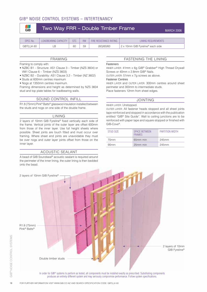
2 layers of 10mm GIB Fyreline®
R1.8 (75mm) Pink® Batts®
2 layers of 10mm GIB Fyreline®
SPEC No. LOADBEARING CAPACITY STC RW FIRE RESISTANCE RATING LINING REQUIREMENTS
GBT(L)A 60 LB 60 59 (60)/60/60 2 x 10mm GIB Fyreline® each side
FRAMINGFraming to comply with:• NZBC B1 – Structure: AS1 Clause 3 – Timber (NZS 3604) or
VM1 Clause 6 – Timber (NZS 3603)• NZBC B2 – Durability: AS1 Clause 3.2 – Timber (NZ 3602) • Studs at 600mm centres maximum• Nogs at 1350mm centres maximum.Framing dimensions and height as determined by NZS 3604 stud and top plate tables for loadbearing walls.
SOUND CONTROL INFILLR1.8 (75mm) Pink® Batts® glasswool insulation installed between the studs and nogs on one side of the double frame.
LINING2 layers of 10mm GIB Fyreline® fixed vertically each side of the frame. Vertical joints of the outer layer are offset 600mm from those of the inner layer. Use full height sheets where possible. Sheet joints are touch fitted and must occur over framing. Where sheet end joints are unavoidable they must be over nogs and outer layer joints offset from those on the inner layer.
ACOUSTIC SEALANTA bead of GIB Soundseal® acoustic sealant is required around the perimeter of the inner lining, the outer lining is then bedded onto the bead.
FASTENING THE LININGFastenersINNER LAYER: 41mm x 6g GIB® Grabber® High Thread Drywall Screws or 40mm x 2.8mm GIB® Nails.OUTER LAYER: 51mm x 7g screws as above.Fastener CentresINNER LAYER and OUTER LAYER: 300mm centres around sheet perimeter and 300mm to intermediate studs. Place fasteners 12mm from sheet edges.
JOINTINGINNER LAYER: Unstopped.OUTER LAYER: All fastener heads stopped and all sheet joints tape reinforced and stopped in accordance with the publication entitled “GIB® Site Guide”. Wall to ceiling junctions are to be reinforced with paper tape and square stopped or finished with GIB-Cove®.
STUD SIZE SPACE BETWEEN FRAMES
PARTITION WIDTH
70mm 65mm min 245mm
90mm 25mm min 245mm
Double timber studs
GIB® NOISE CONTROL SYSTEMS – INTERTENANCY
Two Way FRR – Double Timber Frame MARCH 2006
FOR FURTHER INFORMATION VISIT WWW.GIB.CO.NZ AND SEARCH SPECIFICATION CODE: GBT(L)A 60
In order for GIB® systems to perform as tested, all components must be installed exactly as prescribed. Substituting components produces an entirely different system and may seriously compromise performance. Follow system specifications.
GIB
® N
OIS
E C
ON
TRO
L S
YS
TEM
S
19
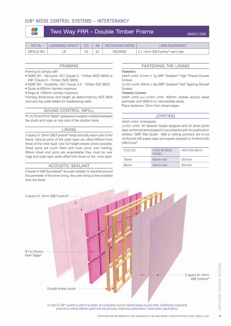
2 layers of 13mm GIB Fyreline®
R1.8 (75mm) Pink® Batts®
2 layers of 13mm GIB Fyreline®
Double timber studs
SPEC No. LOADBEARING CAPACITY STC RW FIRE RESISTANCE RATING LINING REQUIREMENTS
GBT(L)A 90c LB 63 62 (90)/90/90 2 x 13mm GIB Fyreline® each side
FRAMINGFraming to comply with:• NZBC B1 – Structure: AS1 Clause 3 – Timber (NZS 3604) or
VM1 Clause 6 – Timber (NZS 3603)• NZBC B2 – Durability: AS1 Clause 3.2 – Timber (NZ 3602)• Studs at 600mm centres maximum• Nogs at 1350mm centres maximum.Framing dimensions and height as determined by NZS 3604 stud and top plate tables for loadbearing walls.
SOUND CONTROL INFILLR1.8 (75mm) Pink® Batts® glasswool insulation installed between the studs and nogs on one side of the double frame.
LINING2 layers of 13mm GIB Fyreline® fixed vertically each side of the frame. Vertical joints of the outer layer are offset 600mm from those of the inner layer. Use full height sheets where possible. Sheet joints are touch fitted and must occur over framing. Where sheet end joints are unavoidable they must be over nogs and outer layer joints offset from those on the inner layer.
ACOUSTIC SEALANTA bead of GIB Soundseal® acoustic sealant is required around the perimeter of the inner lining, the outer lining is then bedded onto the bead.
FASTENING THE LININGFastenersINNER LAYER: 51mm x 7g GIB® Grabber® High Thread Drywall Screws.OUTER LAYER: 63mm x 8g GIB® Grabber® Self Tapping Drywall Screws.Fastener CentresINNER LAYER and OUTER LAYER: 300mm centres around sheet perimeter and 300mm to intermediate studs.Place fasteners 12mm from sheet edges.
JOINTINGINNER LAYER: Unstopped.OUTER LAYER: All fastener heads stopped and all sheet joints tape reinforced and stopped in accordance with the publication entitled “GIB® Site Guide”. Wall to ceiling junctions are to be reinforced with paper tape and square stopped or finished with GIB-Cove®.
STUD SIZE SPACE BETWEEN FRAMES
PARTITION WIDTH
70mm 65mm min 257mm
90mm 25mm min 257mm
MARCH 2006
FOR FURTHER INFORMATION VISIT WWW.GIB.CO.NZ AND SEARCH SPECIFICATION CODE: GBT(L)A 90c
GIB® NOISE CONTROL SYSTEMS – INTERTENANCY
Two Way FRR – Double Timber Frame MARCH 2006
In order for GIB® systems to perform as tested, all components must be installed exactly as prescribed. Substituting components produces an entirely different system and may seriously compromise performance. Follow system specifications.
GIB
® N
OIS
E C
ON
TRO
L S
YS
TEM
S
20
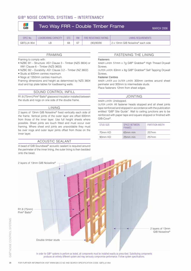
2 layers of 13mm GIB Noiseline®
R1.8 (75mm) Pink® Batts®
2 layers of 13mm GIB Noiseline®
Double timber studs
MARCH 2006
SPEC No. LOADBEARING CAPACITY STC RW FIRE RESISTANCE RATING LINING REQUIREMENTS
GBT(L)A 90d LB 68 67 (90)/90/90 2 x 13mm GIB Noiseline® each side
FRAMINGFraming to comply with:• NZBC B1 – Structure: AS1 Clause 3 – Timber (NZS 3604) or
VM1 Clause 6 – Timber (NZS 3603)• NZBC B2 – Durability: AS1 Clause 3.2 – Timber (NZ 3602)• Studs at 600mm centres maximum• Nogs at 1350mm centres maximum.Framing dimensions and height as determined by NZS 3604 stud and top plate tables for loadbearing walls.
SOUND CONTROL INFILLR1.8 (75mm) Pink® Batts® glasswool insulation installed between the studs and nogs on one side of the double frame.
LINING2 layers of 13mm GIB Noiseline® fixed vertically each side of the frame. Vertical joints of the outer layer are offset 600mm from those of the inner layer. Use full height sheets where possible. Sheet joints are touch fitted and must occur over framing. Where sheet end joints are unavoidable they must be over nogs and outer layer joints offset from those on the inner layer.
ACOUSTIC SEALANTA bead of GIB Soundseal® acoustic sealant is required around the perimeter of the inner lining, the outer lining is then bedded onto the bead.
FASTENING THE LININGFastenersINNER LAYER: 51mm x 7g GIB® Grabber® High Thread Drywall Screws.OUTER LAYER: 63mm x 8g GIB® Grabber® Self Tapping Drywall Screws.Fastener CentresINNER LAYER and OUTER LAYER: 300mm centres around sheet perimeter and 300mm to intermediate studs.Place fasteners 12mm from sheet edges.
JOINTINGINNER LAYER: Unstopped.OUTER LAYER: All fastener heads stopped and all sheet joints tape reinforced and stopped in accordance with the publication entitled “GIB® Site Guide”. Wall to ceiling junctions are to be reinforced with paper tape and square stopped or finished with GIB-Cove®.
STUD SIZE SPACE BETWEEN FRAMES
PARTITION WIDTH
70mm KD 65mm min 257mm
90mm KD 25mm min 257mm
GIB® NOISE CONTROL SYSTEMS – INTERTENANCY
Two Way FRR – Double Timber Frame MARCH 2006
FOR FURTHER INFORMATION VISIT WWW.GIB.CO.NZ AND SEARCH SPECIFICATION CODE: GBT(L)A 90d
In order for GIB® systems to perform as tested, all components must be installed exactly as prescribed. Substituting components produces an entirely different system and may seriously compromise performance. Follow system specifications.
GIB
® N
OIS
E C
ON
TRO
L S
YS
TEM
S
21
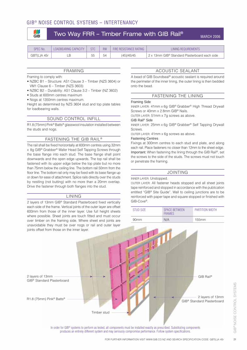
2 layers of 13mm GIB® Standard Plasterboard
R1.8 (75mm) Pink® Batts®
Timber stud
2 layers of 13mm GIB® Standard Plasterboard
GIB Rail®
In order for GIB® systems to perform as tested, all components must be installed exactly as prescribed. Substituting components produces an entirely different system and may seriously compromise performance. Follow system specifications.
SPEC No. LOADBEARING CAPACITY STC RW FIRE RESISTANCE RATING LINING REQUIREMENTS
GBT(L)A 45r LB 55 54 (45)/45/45 2 x 13mm GIB® Standard Plasterboard each side
FRAMINGFraming to comply with:• NZBC B1 – Structure: AS1 Clause 3 – Timber (NZS 3604) or
VM1 Clause 6 – Timber (NZS 3603)• NZBC B2 – Durability: AS1 Clause 3.2 – Timber (NZ 3602)• Studs at 600mm centres maximum• Nogs at 1350mm centres maximum.Height as determined by NZS 3604 stud and top plate tables for loadbearing walls.
SOUND CONTROL INFILLR1.8 (75mm) Pink® Batts® glasswool insulation installed between the studs and nogs.
FASTENING THE GIB RAIL®
The rail shall be fixed horizontally at 600mm centres using 32mm x 8g GIB® Grabber® Wafer Head Self Tapping Screws through the base flange into each stud. The base flange shall point downwards and the open edge upwards. The top rail shall be fastened with its upper edge below the top plate but no more than 75mm below the ceiling line. The bottom rail 50mm from the floor line. The bottom rail only may be fixed with its base flange up or down for ease of attachment. Splice rails directly over the studs by nestling (not butting) with no more than a 20mm overlap. Drive the fastener through both flanges into the stud.
LINING2 layers of 13mm GIB® Standard Plasterboard fixed vertically each side of the frame. Vertical joints of the outer layer are offset 600mm from those of the inner layer. Use full height sheets where possible. Sheet joints are touch fitted and must occur over timber on the framing side. Where sheet end joints are unavoidable they must be over nogs or rail and outer layer joints offset from those on the inner layer.
ACOUSTIC SEALANTA bead of GIB Soundseal® acoustic sealant is required around the perimeter of the inner lining, the outer lining is then bedded onto the bead.
FASTENING THE LININGFraming SideINNER LAYER: 41mm x 6g GIB® Grabber® High Thread Drywall Screws or 40mm x 2.8mm GIB® Nails.OUTER LAYER: 51mm x 7g screws as above.GIB Rail® SideINNER LAYER: 25mm x 6g GIB® Grabber® Self Tapping Drywall Screws.OUTER LAYER: 41mm x 6g screws as above.Fastening CentresFixings at 300mm centres to each stud and plate, and along each rail. Place fasteners no closer than 12mm to the sheet edge.Important: When fastening the lining through the GIB Rail®, set the screws to the side of the studs. The screws must not touch or penetrate the framing.
JOINTINGINNER LAYER: Unstopped.OUTER LAYER: All fastener heads stopped and all sheet joints tape reinforced and stopped in accordance with the publication entitled “GIB® Site Guide”. Wall to ceiling junctions are to be reinforced with paper tape and square stopped or finished with GIB-Cove®.
STUD SIZE SPACE BETWEEN FRAMES
PARTITION WIDTH
90mm N/A 155mm
MARCH 2006
FOR FURTHER INFORMATION VISIT WWW.GIB.CO.NZ AND SEARCH SPECIFICATION CODE: GBT(L)A 45r
GIB® NOISE CONTROL SYSTEMS – INTERTENANCY
Two Way FRR – Timber Frame with GIB Rail® MARCH 2006
GIB
® N
OIS
E C
ON
TRO
L S
YS
TEM
S
22
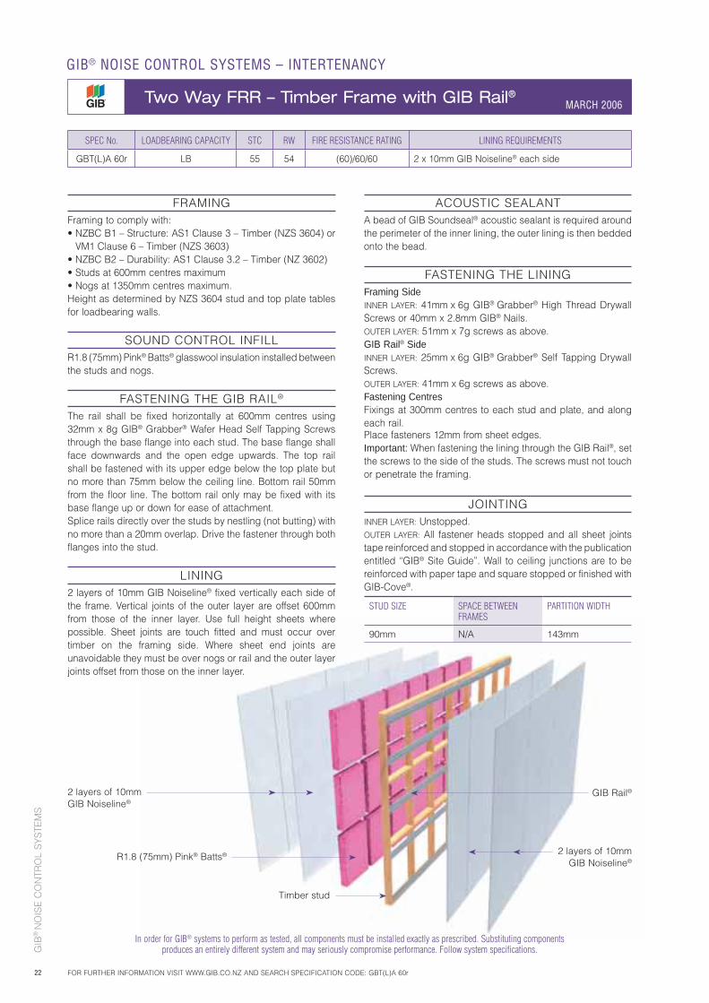
2 layers of 10mm GIB Noiseline®
R1.8 (75mm) Pink® Batts®
Timber stud
2 layers of 10mm GIB Noiseline®
GIB Rail®
In order for GIB® systems to perform as tested, all components must be installed exactly as prescribed. Substituting components produces an entirely different system and may seriously compromise performance. Follow system specifications.
SPEC No. LOADBEARING CAPACITY STC RW FIRE RESISTANCE RATING LINING REQUIREMENTS
GBT(L)A 60r LB 55 54 (60)/60/60 2 x 10mm GIB Noiseline® each side
FRAMINGFraming to comply with:• NZBC B1 – Structure: AS1 Clause 3 – Timber (NZS 3604) or
VM1 Clause 6 – Timber (NZS 3603)• NZBC B2 – Durability: AS1 Clause 3.2 – Timber (NZ 3602)• Studs at 600mm centres maximum• Nogs at 1350mm centres maximum.Height as determined by NZS 3604 stud and top plate tables for loadbearing walls.
SOUND CONTROL INFILLR1.8 (75mm) Pink® Batts® glasswool insulation installed between the studs and nogs.
FASTENING THE GIB RAIL®
The rail shall be fixed horizontally at 600mm centres using 32mm x 8g GIB® Grabber® Wafer Head Self Tapping Screws through the base flange into each stud. The base flange shall face downwards and the open edge upwards. The top rail shall be fastened with its upper edge below the top plate but no more than 75mm below the ceiling line. Bottom rail 50mm from the floor line. The bottom rail only may be fixed with its base flange up or down for ease of attachment.Splice rails directly over the studs by nestling (not butting) with no more than a 20mm overlap. Drive the fastener through both flanges into the stud.
LINING2 layers of 10mm GIB Noiseline® fixed vertically each side of the frame. Vertical joints of the outer layer are offset 600mm from those of the inner layer. Use full height sheets where possible. Sheet joints are touch fitted and must occur over timber on the framing side. Where sheet end joints are unavoidable they must be over nogs or rail and the outer layer joints offset from those on the inner layer.
ACOUSTIC SEALANTA bead of GIB Soundseal® acoustic sealant is required around the perimeter of the inner lining, the outer lining is then bedded onto the bead.
FASTENING THE LININGFraming SideINNER LAYER: 41mm x 6g GIB® Grabber® High Thread Drywall Screws or 40mm x 2.8mm GIB® Nails.OUTER LAYER: 51mm x 7g screws as above.GIB Rail® SideINNER LAYER: 25mm x 6g GIB® Grabber® Self Tapping Drywall Screws.OUTER LAYER: 41mm x 6g screws as above.Fastening CentresFixings at 300mm centres to each stud and plate, and along each rail. Place fasteners 12mm from sheet edges.Important: When fastening the lining through the GIB Rail®, set the screws to the side of the studs. The screws must not touch or penetrate the framing.
JOINTINGINNER LAYER: Unstopped.OUTER LAYER: All fastener heads stopped and all sheet joints tape reinforced and stopped in accordance with the publication entitled “GIB® Site Guide”. Wall to ceiling junctions are to be reinforced with paper tape and square stopped or finished with GIB-Cove®.
STUD SIZE SPACE BETWEEN FRAMES
PARTITION WIDTH
90mm N/A 143mm
MARCH 2006
GIB® NOISE CONTROL SYSTEMS – INTERTENANCY
Two Way FRR – Timber Frame with GIB Rail® MARCH 2006
FOR FURTHER INFORMATION VISIT WWW.GIB.CO.NZ AND SEARCH SPECIFICATION CODE: GBT(L)A 60r
GIB
® N
OIS
E C
ON
TRO
L S
YS
TEM
S
23
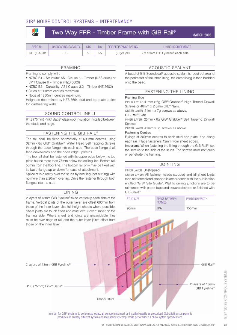
2 layers of 13mm GIB Fyreline®
R1.8 (75mm) Pink® Batts®
Timber stud
2 layers of 13mm GIB Fyreline®
GIB Rail®
In order for GIB® systems to perform as tested, all components must be installed exactly as prescribed. Substituting components produces an entirely different system and may seriously compromise performance. Follow system specifications.
SPEC No. LOADBEARING CAPACITY STC RW FIRE RESISTANCE RATING LINING REQUIREMENTS
GBT(L)A 90r LB 55 55 (90)/90/90 2 x 13mm GIB Fyreline® each side
FRAMINGFraming to comply with:• NZBC B1 – Structure: AS1 Clause 3 – Timber (NZS 3604) or
VM1 Clause 6 – Timber (NZS 3603)• NZBC B2 – Durability: AS1 Clause 3.2 – Timber (NZ 3602)• Studs at 600mm centres maximum• Nogs at 1350mm centres maximum.Height as determined by NZS 3604 stud and top plate tables for loadbearing walls.
SOUND CONTROL INFILLR1.8 (75mm) Pink® Batts® glasswool insulation installed between the studs and nogs.
FASTENING THE GIB RAIL®
The rail shall be fixed horizontally at 600mm centres using 32mm x 8g GIB® Grabber® Wafer Head Self Tapping Screws through the base flange into each stud. The base flange shall face downwards and the open edge upwards.The top rail shall be fastened with its upper edge below the top plate but no more than 75mm below the ceiling line. Bottom rail 50mm from the floor line. The bottom rail only may be fixed with its base flange up or down for ease of attachment.Splice rails directly over the studs by nestling (not butting) with no more than a 20mm overlap. Drive the fastener through both flanges into the stud.
LINING2 layers of 13mm GIB Fyreline® fixed vertically each side of the frame. Vertical joints of the outer layer are offset 600mm from those of the inner layer. Use full height sheets where possible. Sheet joints are touch fitted and must occur over timber on the framing side. Where sheet end joints are unavoidable they must be over nogs or rail and the outer layer joints offset from those on the inner layer.
ACOUSTIC SEALANTA bead of GIB Soundseal® acoustic sealant is required around the perimeter of the inner lining, the outer lining is then bedded onto the bead.
FASTENING THE LININGFraming SideINNER LAYER: 41mm x 6g GIB® Grabber® High Thread Drywall Screws or 40mm x 2.8mm GIB® Nails.OUTER LAYER: 51mm x 7g screws as above.GIB Rail® SideINNER LAYER: 25mm x 6g GIB® Grabber® Self Tapping Drywall Screws.OUTER LAYER: 41mm x 6g screws as above.Fastening CentresFixings at 300mm centres to each stud and plate, and along each rail. Place fasteners 12mm from sheet edges.Important: When fastening the lining through the GIB Rail®, set the screws to the side of the studs. The screws must not touch or penetrate the framing.
JOINTINGINNER LAYER: Unstopped.OUTER LAYER: All fastener heads stopped and all sheet joints tape reinforced and stopped in accordance with the publication entitled “GIB® Site Guide”. Wall to ceiling junctions are to be reinforced with paper tape and square stopped or finished with GIB-Cove®.
STUD SIZE SPACE BETWEEN FRAMES
PARTITION WIDTH
90mm N/A 155mm
FOR FURTHER INFORMATION VISIT WWW.GIB.CO.NZ AND SEARCH SPECIFICATION CODE: GBT(L)A 90r
GIB® NOISE CONTROL SYSTEMS – INTERTENANCY
Two Way FRR – Timber Frame with GIB Rail® MARCH 2006
GIB
® N
OIS
E C
ON
TRO
L S
YS
TEM
S
24
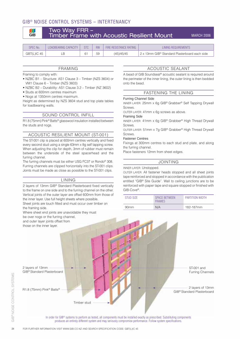
2 layers of 13mm GIB® Standard Plasterboard
R1.8 (75mm) Pink® Batts®
Timber stud
2 layers of 13mm GIB® Standard Plasterboard
ST-001 and Furring Channels
In order for GIB® systems to perform as tested, all components must be installed exactly as prescribed. Substituting components produces an entirely different system and may seriously compromise performance. Follow system specifications.
SPEC No. LOADBEARING CAPACITY STC RW FIRE RESISTANCE RATING LINING REQUIREMENTS
GBT(L)IC 45 LB 61 59 (45)/45/45 2 x 13mm GIB® Standard Plasterboard each side
FRAMINGFraming to comply with:• NZBC B1 – Structure: AS1 Clause 3 – Timber (NZS 3604) or
VM1 Clause 6 – Timber (NZS 3603)• NZBC B2 – Durability: AS1 Clause 3.2 – Timber (NZ 3602)• Studs at 600mm centres maximum• Nogs at 1350mm centres maximum.Height as determined by NZS 3604 stud and top plate tables for loadbearing walls.
SOUND CONTROL INFILLR1.8 (75mm) Pink® Batts® glasswool insulation installed between the studs and nogs.
ACOUSTIC RESILIENT MOUNT (ST-001)The ST-001 clip is placed at 600mm centres vertically and fixed every second stud using a single 63mm x 8g self tapping screw. When adjusting the clip for depth, 3mm of rubber must remain between the underside of the steel spacerhead and the furring channel.The furring channels must be either USG FC37 or Rondo® 308.Furring channels are clipped horizontally into the ST-001 clips. Joints must be made as close as possible to the ST-001 clips.
LINING2 layers of 13mm GIB® Standard Plasterboard fixed vertically to the frame on one side and to the furring channel on the other. Vertical joints of the outer layer are offset 600mm from those of the inner layer. Use full height sheets where possible. Sheet joints are touch fitted and must occur over timber on the framing side. Where sheet end joints are unavoidable they must be over nogs or the furring channel, and outer layer joints offset from those on the inner layer.
ACOUSTIC SEALANTA bead of GIB Soundseal® acoustic sealant is required around the perimeter of the inner lining, the outer lining is then bedded onto the bead.
FASTENING THE LININGFurring Channel SideINNER LAYER: 25mm x 6g GIB® Grabber® Self Tapping Drywall Screws.OUTER LAYER: 41mm x 6g screws as above.Framing Side INNER LAYER: 41mm x 6g GIB® Grabber® High Thread Drywall Screws. OUTER LAYER: 51mm x 7g GIB® Grabber® High Thread Drywall Screws.Fastener CentresFixings at 300mm centres to each stud and plate, and along the furring channel. Place fasteners 12mm from sheet edges.
JOINTINGINNER LAYER: Unstopped.OUTER LAYER: All fastener heads stopped and all sheet joints tape reinforced and stopped in accordance with the publication entitled “GIB® Site Guide”. Wall to ceiling junctions are to be reinforced with paper tape and square stopped or finished with GIB-Cove®.
STUD SIZE SPACE BETWEEN FRAMES
PARTITION WIDTH
90mm N/A 182-187mm
GIB® NOISE CONTROL SYSTEMS – INTERTENANCY
Two Way FRR – Timber Frame with Acoustic Resilient Mount MARCH 2006
FOR FURTHER INFORMATION VISIT WWW.GIB.CO.NZ AND SEARCH SPECIFICATION CODE: GBT(L)IC 45
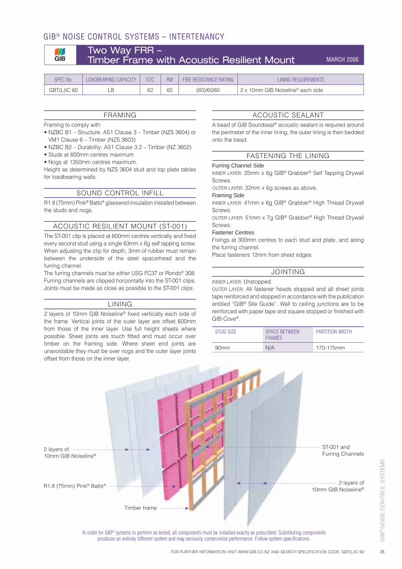
GIB
® N
OIS
E C
ON
TRO
L S
YS
TEM
S
25
2 layers of 10mm GIB Noiseline®
R1.8 (75mm) Pink® Batts® 2 layers of 10mm GIB Noiseline®
In order for GIB® systems to perform as tested, all components must be installed exactly as prescribed. Substituting components produces an entirely different system and may seriously compromise performance. Follow system specifications.
FRAMINGFraming to comply with:• NZBC B1 – Structure: AS1 Clause 3 – Timber (NZS 3604) or
VM1 Clause 6 – Timber (NZS 3603)• NZBC B2 – Durability: AS1 Clause 3.2 – Timber (NZ 3602)• Studs at 600mm centres maximum• Nogs at 1350mm centres maximum.Height as determined by NZS 3604 stud and top plate tables for loadbearing walls.
SOUND CONTROL INFILLR1.8 (75mm) Pink® Batts® glasswool insulation installed between the studs and nogs.
ACOUSTIC RESILIENT MOUNT (ST-001)The ST-001 clip is placed at 600mm centres vertically and fixed every second stud using a single 63mm x 8g self tapping screw. When adjusting the clip for depth, 3mm of rubber must remain between the underside of the steel spacerhead and the furring channel.The furring channels must be either USG FC37 or Rondo® 308.Furring channels are clipped horizontally into the ST-001 clips. Joints must be made as close as possible to the ST-001 clips.
LINING2 layers of 10mm GIB Noiseline® fixed vertically each side of the frame. Vertical joints of the outer layer are offset 600mm from those of the inner layer. Use full height sheets where possible. Sheet joints are touch fitted and must occur over timber on the framing side. Where sheet end joints are unavoidable they must be over nogs and the outer layer joints offset from those on the inner layer.
ACOUSTIC SEALANTA bead of GIB Soundseal® acoustic sealant is required around the perimeter of the inner lining, the outer lining is then bedded onto the bead.
FASTENING THE LININGFurring Channel SideINNER LAYER: 25mm x 6g GIB® Grabber® Self Tapping Drywall Screws.OUTER LAYER: 32mm x 6g screws as above.Framing Side INNER LAYER: 41mm x 6g GIB® Grabber® High Thread Drywall Screws.OUTER LAYER: 51mm x 7g GIB® Grabber® High Thread Drywall Screws.Fastener Centres Fixings at 300mm centres to each stud and plate, and along the furring channel.Place fasteners 12mm from sheet edges.
JOINTINGINNER LAYER: Unstopped.OUTER LAYER: All fastener heads stopped and all sheet joints tape reinforced and stopped in accordance with the publication entitled “GIB® Site Guide”. Wall to ceiling junctions are to be reinforced with paper tape and square stopped or finished with GIB-Cove®.
STUD SIZE SPACE BETWEEN FRAMES
PARTITION WIDTH
90mm N/A 170-175mm
SPEC No. LOADBEARING CAPACITY STC RW FIRE RESISTANCE RATING LINING REQUIREMENTS
GBT(L)IC 60 LB 62 60 (60)/60/60 2 x 10mm GIB Noiseline® each side
ST-001 and Furring Channels
Timber frame
FOR FURTHER INFORMATION VISIT WWW.GIB.CO.NZ AND SEARCH SPECIFICATION CODE: GBT(L)IC 60
GIB® NOISE CONTROL SYSTEMS – INTERTENANCY
Two Way FRR – Timber Frame with Acoustic Resilient Mount MARCH 2006
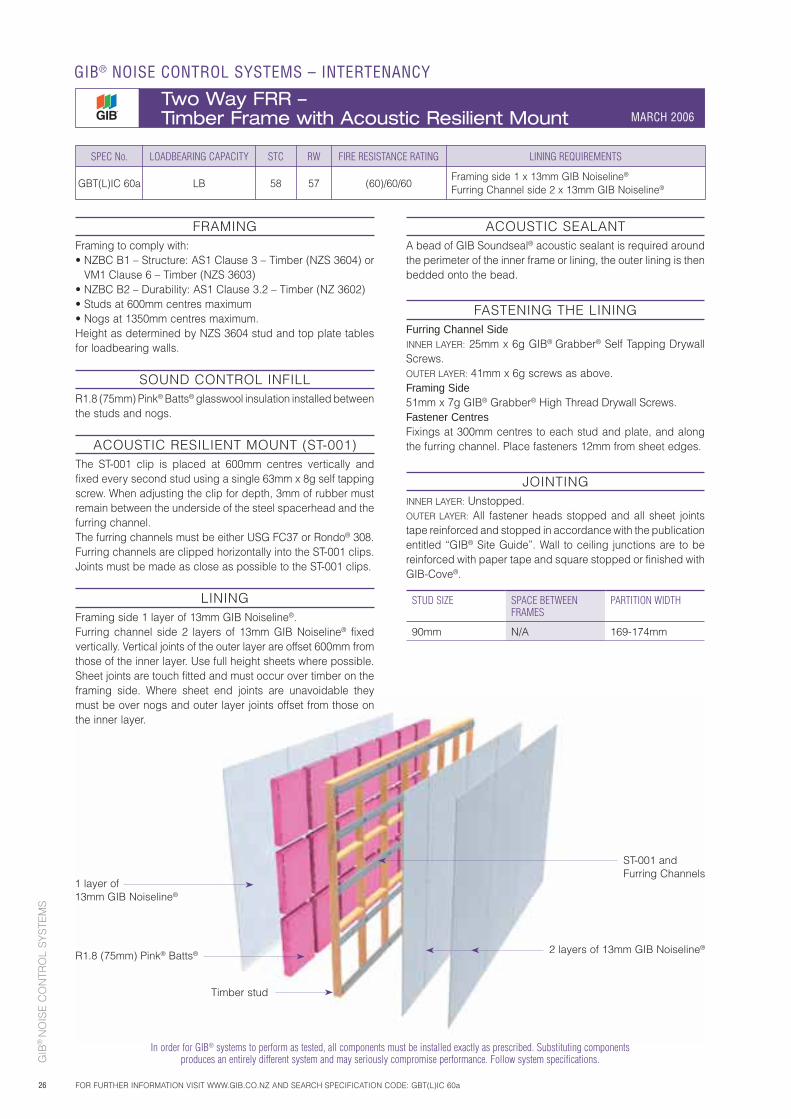
GIB
® N
OIS
E C
ON
TRO
L S
YS
TEM
S
26
1 layer of 13mm GIB Noiseline®
2 layers of 13mm GIB Noiseline®
Timber stud
In order for GIB® systems to perform as tested, all components must be installed exactly as prescribed. Substituting components produces an entirely different system and may seriously compromise performance. Follow system specifications.
FRAMINGFraming to comply with:• NZBC B1 – Structure: AS1 Clause 3 – Timber (NZS 3604) or
VM1 Clause 6 – Timber (NZS 3603)• NZBC B2 – Durability: AS1 Clause 3.2 – Timber (NZ 3602)• Studs at 600mm centres maximum• Nogs at 1350mm centres maximum.Height as determined by NZS 3604 stud and top plate tables for loadbearing walls.
SOUND CONTROL INFILLR1.8 (75mm) Pink® Batts® glasswool insulation installed between the studs and nogs.
ACOUSTIC RESILIENT MOUNT (ST-001)The ST-001 clip is placed at 600mm centres vertically and fixed every second stud using a single 63mm x 8g self tapping screw. When adjusting the clip for depth, 3mm of rubber must remain between the underside of the steel spacerhead and the furring channel.The furring channels must be either USG FC37 or Rondo® 308.Furring channels are clipped horizontally into the ST-001 clips. Joints must be made as close as possible to the ST-001 clips.
LININGFraming side 1 layer of 13mm GIB Noiseline®. Furring channel side 2 layers of 13mm GIB Noiseline® fixed vertically. Vertical joints of the outer layer are offset 600mm from those of the inner layer. Use full height sheets where possible. Sheet joints are touch fitted and must occur over timber on the framing side. Where sheet end joints are unavoidable they must be over nogs and outer layer joints offset from those on the inner layer.
ACOUSTIC SEALANTA bead of GIB Soundseal® acoustic sealant is required around the perimeter of the inner frame or lining, the outer lining is then bedded onto the bead.
FASTENING THE LININGFurring Channel SideINNER LAYER: 25mm x 6g GIB® Grabber® Self Tapping Drywall Screws.OUTER LAYER: 41mm x 6g screws as above.Framing Side 51mm x 7g GIB® Grabber® High Thread Drywall Screws.Fastener Centres Fixings at 300mm centres to each stud and plate, and along the furring channel. Place fasteners 12mm from sheet edges.
JOINTINGINNER LAYER: Unstopped.OUTER LAYER: All fastener heads stopped and all sheet joints tape reinforced and stopped in accordance with the publication entitled “GIB® Site Guide”. Wall to ceiling junctions are to be reinforced with paper tape and square stopped or finished with GIB-Cove®.
SPEC No. LOADBEARING CAPACITY STC RW FIRE RESISTANCE RATING LINING REQUIREMENTS
GBT(L)IC 60a LB 58 57 (60)/60/60Framing side 1 x 13mm GIB Noiseline®
Furring Channel side 2 x 13mm GIB Noiseline®
STUD SIZE SPACE BETWEEN FRAMES
PARTITION WIDTH
90mm N/A 169-174mm
R1.8 (75mm) Pink® Batts®
ST-001 and Furring Channels
GIB® NOISE CONTROL SYSTEMS – INTERTENANCY
Two Way FRR – Timber Frame with Acoustic Resilient Mount MARCH 2006
FOR FURTHER INFORMATION VISIT WWW.GIB.CO.NZ AND SEARCH SPECIFICATION CODE: GBT(L)IC 60a
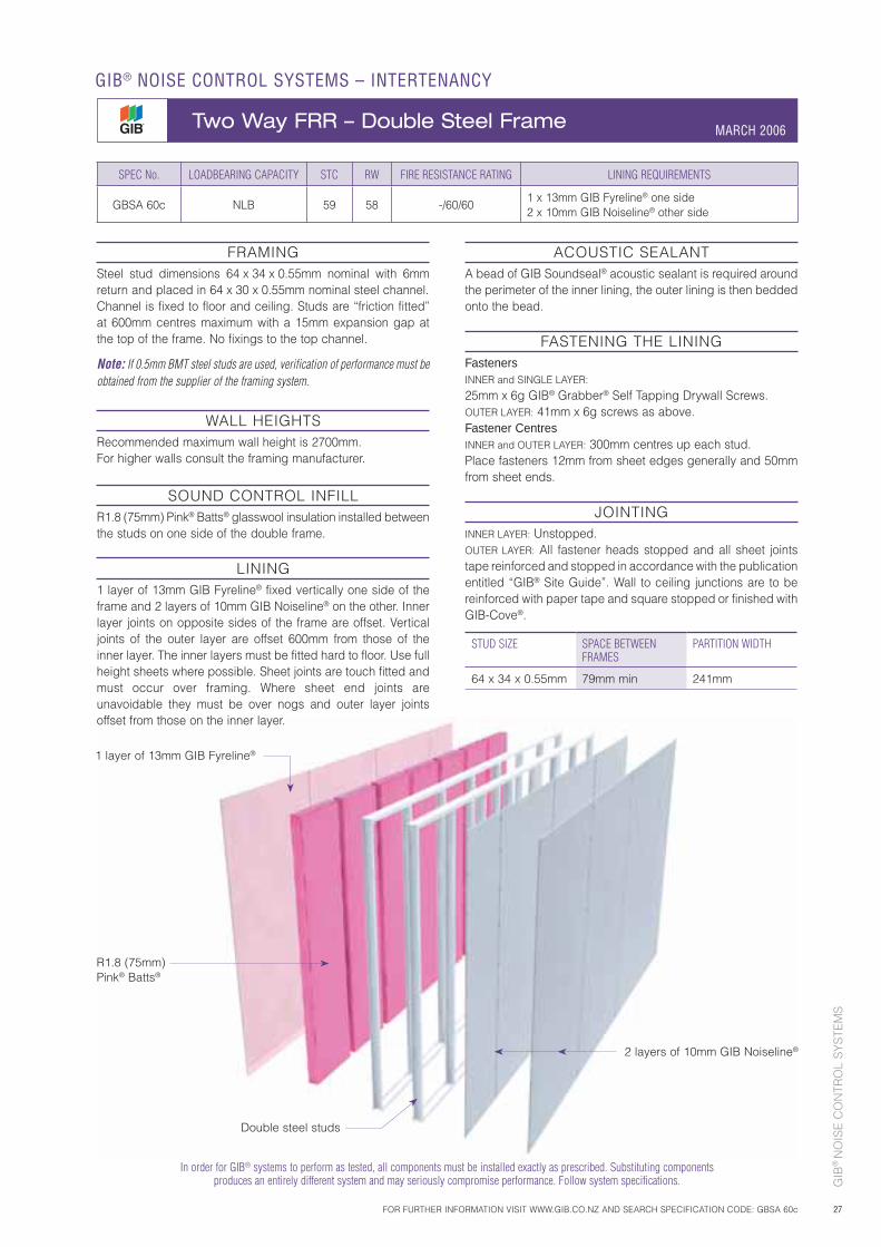
GIB
® N
OIS
E C
ON
TRO
L S
YS
TEM
S
27
ACOUSTIC SEALANTA bead of GIB Soundseal® acoustic sealant is required around the perimeter of the inner lining, the outer lining is then bedded onto the bead.
FASTENING THE LININGFastenersINNER and SINGLE LAYER:
25mm x 6g GIB® Grabber® Self Tapping Drywall Screws. OUTER LAYER: 41mm x 6g screws as above.Fastener CentresINNER and OUTER LAYER: 300mm centres up each stud.Place fasteners 12mm from sheet edges generally and 50mm from sheet ends.
JOINTINGINNER LAYER: Unstopped.OUTER LAYER: All fastener heads stopped and all sheet joints tape reinforced and stopped in accordance with the publication entitled “GIB® Site Guide”. Wall to ceiling junctions are to be reinforced with paper tape and square stopped or finished with GIB-Cove®.
SPEC No. LOADBEARING CAPACITY STC RW FIRE RESISTANCE RATING LINING REQUIREMENTS
GBSA 60c NLB 59 58 -/60/601 x 13mm GIB Fyreline® one side2 x 10mm GIB Noiseline® other side
STUD SIZE SPACE BETWEEN FRAMES
PARTITION WIDTH
64 x 34 x 0.55mm 79mm min 241mm
FOR FURTHER INFORMATION VISIT WWW.GIB.CO.NZ AND SEARCH SPECIFICATION CODE: GBSA 60c
GIB® NOISE CONTROL SYSTEMS – INTERTENANCY
Two Way FRR – Double Steel Frame MARCH 2006
R1.8 (75mm) Pink® Batts®
2 layers of 10mm GIB Noiseline®
Double steel studs
In order for GIB® systems to perform as tested, all components must be installed exactly as prescribed. Substituting components produces an entirely different system and may seriously compromise performance. Follow system specifications.
FRAMINGSteel stud dimensions 64 x 34 x 0.55mm nominal with 6mm return and placed in 64 x 30 x 0.55mm nominal steel channel.Channel is fixed to floor and ceiling. Studs are “friction fitted” at 600mm centres maximum with a 15mm expansion gap at the top of the frame. No fixings to the top channel.
Note: If 0.5mm BMT steel studs are used, verification of performance must be obtained from the supplier of the framing system.
WALL HEIGHTSRecommended maximum wall height is 2700mm. For higher walls consult the framing manufacturer.
SOUND CONTROL INFILLR1.8 (75mm) Pink® Batts® glasswool insulation installed between the studs on one side of the double frame.
LINING1 layer of 13mm GIB Fyreline® fixed vertically one side of the frame and 2 layers of 10mm GIB Noiseline® on the other. Inner layer joints on opposite sides of the frame are offset. Vertical joints of the outer layer are offset 600mm from those of the inner layer. The inner layers must be fitted hard to floor. Use full height sheets where possible. Sheet joints are touch fitted and must occur over framing. Where sheet end joints are unavoidable they must be over nogs and outer layer joints offset from those on the inner layer.
1 layer of 13mm GIB Fyreline®
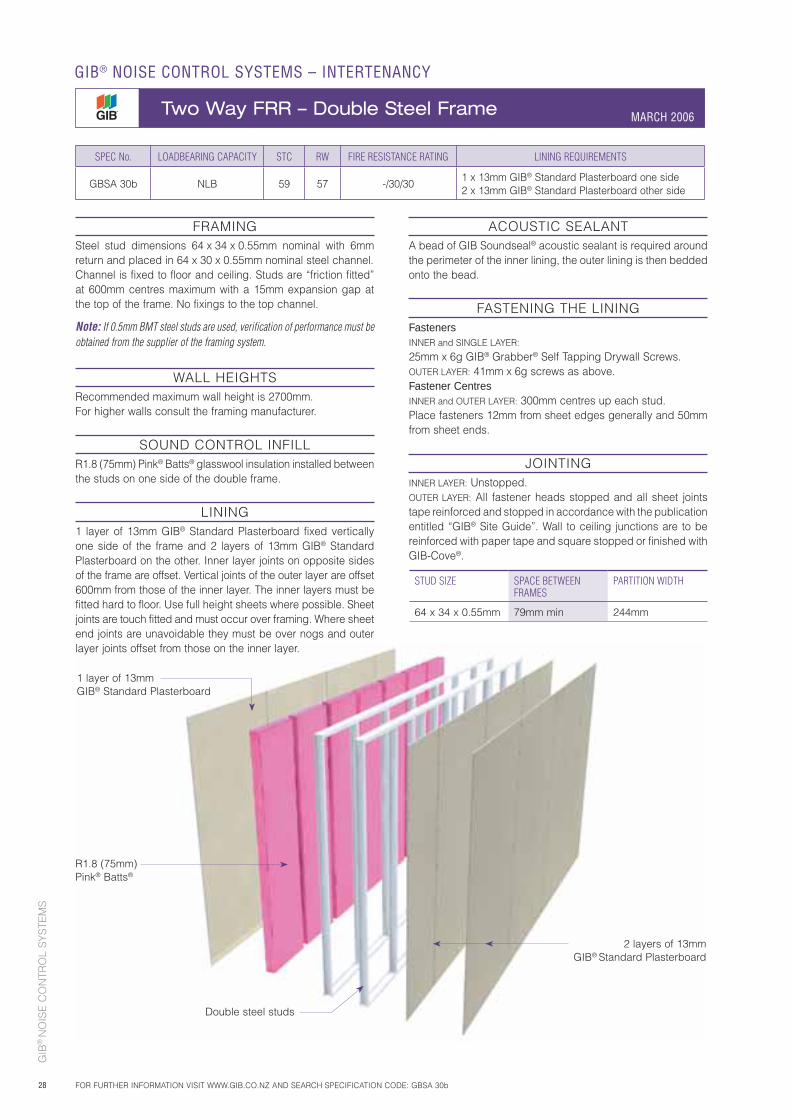
GIB
® N
OIS
E C
ON
TRO
L S
YS
TEM
S
28
ACOUSTIC SEALANTA bead of GIB Soundseal® acoustic sealant is required around the perimeter of the inner lining, the outer lining is then bedded onto the bead.
FASTENING THE LININGFastenersINNER and SINGLE LAYER: 25mm x 6g GIB® Grabber® Self Tapping Drywall Screws. OUTER LAYER: 41mm x 6g screws as above.Fastener CentresINNER and OUTER LAYER: 300mm centres up each stud.Place fasteners 12mm from sheet edges generally and 50mm from sheet ends.
JOINTINGINNER LAYER: Unstopped.OUTER LAYER: All fastener heads stopped and all sheet joints tape reinforced and stopped in accordance with the publication entitled “GIB® Site Guide”. Wall to ceiling junctions are to be reinforced with paper tape and square stopped or finished with GIB-Cove®.
R1.8 (75mm) Pink® Batts®
2 layers of 13mm GIB® Standard Plasterboard
Double steel studs
FRAMINGSteel stud dimensions 64 x 34 x 0.55mm nominal with 6mm return and placed in 64 x 30 x 0.55mm nominal steel channel.Channel is fixed to floor and ceiling. Studs are “friction fitted” at 600mm centres maximum with a 15mm expansion gap at the top of the frame. No fixings to the top channel.
Note: If 0.5mm BMT steel studs are used, verification of performance must be obtained from the supplier of the framing system.
WALL HEIGHTSRecommended maximum wall height is 2700mm. For higher walls consult the framing manufacturer.
SOUND CONTROL INFILLR1.8 (75mm) Pink® Batts® glasswool insulation installed between the studs on one side of the double frame.
LINING1 layer of 13mm GIB® Standard Plasterboard fixed vertically one side of the frame and 2 layers of 13mm GIB® Standard Plasterboard on the other. Inner layer joints on opposite sides of the frame are offset. Vertical joints of the outer layer are offset 600mm from those of the inner layer. The inner layers must be fitted hard to floor. Use full height sheets where possible. Sheet joints are touch fitted and must occur over framing. Where sheet end joints are unavoidable they must be over nogs and outer layer joints offset from those on the inner layer.
1 layer of 13mm GIB® Standard Plasterboard
STUD SIZE SPACE BETWEEN FRAMES
PARTITION WIDTH
64 x 34 x 0.55mm 79mm min 244mm
GIB® NOISE CONTROL SYSTEMS – INTERTENANCY
Two Way FRR – Double Steel Frame MARCH 2006
FOR FURTHER INFORMATION VISIT WWW.GIB.CO.NZ AND SEARCH SPECIFICATION CODE: GBSA 30b
SPEC No. LOADBEARING CAPACITY STC RW FIRE RESISTANCE RATING LINING REQUIREMENTS
GBSA 30b NLB 59 57 -/30/301 x 13mm GIB® Standard Plasterboard one side2 x 13mm GIB® Standard Plasterboard other side
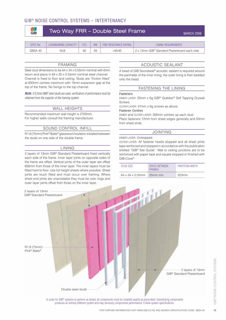
GIB
® N
OIS
E C
ON
TRO
L S
YS
TEM
S
29
SPEC No. LOADBEARING CAPACITY STC RW FIRE RESISTANCE RATING LINING REQUIREMENTS
GBSA 45 NLB 60 59 -/45/45 2 x 13mm GIB® Standard Plasterboard each side
FRAMINGSteel stud dimensions to be 64 x 34 x 0.55mm nominal with 6mm return and place in 64 x 30 x 0.55mm nominal steel channel.Channel is fixed to floor and ceiling. Studs are “friction fitted” at 600mm centres maximum with 15mm expansion gap at the top of the frame. No fixings to the top channel.
Note: If 0.5mm BMT steel studs are used, verification of performance must be obtained from the supplier of the framing system.
WALL HEIGHTS Recommended maximum wall height is 2700mm. For higher walls consult the framing manufacturer.
SOUND CONTROL INFILLR1.8 (75mm) Pink® Batts® glasswool insulation installed between the studs on one side of the double frame.
LINING2 layers of 13mm GIB® Standard Plasterboard fixed vertically each side of the frame. Inner layer joints on opposite sides of the frame are offset. Vertical joints of the outer layer are offset 600mm from those of the inner layer. The inner layers must be fitted hard to floor. Use full height sheets where possible. Sheet joints are touch fitted and must occur over framing. Where sheet end joints are unavoidable they must be over nogs and outer layer joints offset from those on the inner layer.
ACOUSTIC SEALANTA bead of GIB Soundseal® acoustic sealant is required around the perimeter of the inner lining, the outer lining is then bedded onto the bead.
FASTENING THE LININGFastenersINNER LAYER: 25mm x 6g GIB® Grabber® Self Tapping Drywall Screws.OUTER LAYER: 41mm x 6g screws as above.Fastener CentresINNER and OUTER LAYER: 300mm centres up each stud.Place fasteners 12mm from sheet edges generally and 50mm from sheet ends.
JOINTINGINNER LAYER: Unstopped.OUTER LAYER: All fastener heads stopped and all sheet joints tape reinforced and stopped in accordance with the publication entitled “GIB® Site Guide”. Wall to ceiling junctions are to be reinforced with paper tape and square stopped or finished with GIB-Cove®.
STUD SIZE SPACE BETWEEN FRAMES
PARTITION WIDTH
64 x 34 x 0.55mm 25mm min 203mm
In order for GIB® systems to perform as tested, all components must be installed exactly as prescribed. Substituting components produces an entirely different system and may seriously compromise performance. Follow system specifications.
2 layers of 13mm GIB® Standard Plasterboard
R1.8 (75mm) Pink® Batts®
2 layers of 13mm GIB® Standard Plasterboard
Double steel studs
FOR FURTHER INFORMATION VISIT WWW.GIB.CO.NZ AND SEARCH SPECIFICATION CODE: GBSA 45
GIB® NOISE CONTROL SYSTEMS – INTERTENANCY
Two Way FRR – Double Steel Frame MARCH 2006
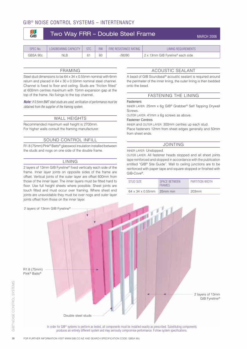
GIB
® N
OIS
E C
ON
TRO
L S
YS
TEM
S
30
2 layers of 13mm GIB Fyreline®
R1.8 (75mm) Pink® Batts®
2 layers of 13mm GIB Fyreline®
SPEC No. LOADBEARING CAPACITY STC RW FIRE RESISTANCE RATING LINING REQUIREMENTS
GBSA 90c NLB 61 60 -/90/90 2 x 13mm GIB Fyreline® each side
FRAMINGSteel stud dimensions to be 64 x 34 x 0.55mm nominal with 6mm return and placed in 64 x 30 x 0.55mm nominal steel channel.Channel is fixed to floor and ceiling. Studs are “friction fitted” at 600mm centres maximum with 15mm expansion gap at the top of the frame. No fixings to the top channel.
Note: If 0.5mm BMT steel studs are used, verification of performance must be obtained from the supplier of the framing system.
WALL HEIGHTS Recommended maximum wall height is 2700mm. For higher walls consult the framing manufacturer.
SOUND CONTROL INFILLR1.8 (75mm) Pink® Batts® glasswool insulation installed between the studs and nogs on one side of the double frame.
LINING2 layers of 13mm GIB Fyreline® fixed vertically each side of the frame. Inner layer joints on opposite sides of the frame are offset. Vertical joints of the outer layer are offset 600mm from those of the inner layer. The inner layers must be fitted hard to floor. Use full height sheets where possible. Sheet joints are touch fitted and must occur over framing. Where sheet end joints are unavoidable they must be over nogs and outer layer joints offset from those on the inner layer.
ACOUSTIC SEALANTA bead of GIB Soundseal® acoustic sealant is required around the perimeter of the inner lining, the outer lining is then bedded onto the bead.
FASTENING THE LININGFastenersINNER LAYER: 25mm x 6g GIB® Grabber® Self Tapping Drywall Screws.OUTER LAYER: 41mm x 6g screws as above.Fastener CentresINNER and OUTER LAYER: 300mm centres up each stud.Place fasteners 12mm from sheet edges generally and 50mm from sheet ends.
JOINTINGINNER LAYER: Unstopped.OUTER LAYER: All fastener heads stopped and all sheet joints tape reinforced and stopped in accordance with the publication entitled “GIB® Site Guide”. Wall to ceiling junctions are to be reinforced with paper tape and square stopped or finished with GIB-Cove®.
STUD SIZE SPACE BETWEEN FRAMES
PARTITION WIDTH
64 x 34 x 0.55mm 25mm min 203mm
In order for GIB® systems to perform as tested, all components must be installed exactly as prescribed. Substituting components produces an entirely different system and may seriously compromise performance. Follow system specifications.
Double steel studs
GIB® NOISE CONTROL SYSTEMS – INTERTENANCY
Two Way FRR – Double Steel Frame MARCH 2006
FOR FURTHER INFORMATION VISIT WWW.GIB.CO.NZ AND SEARCH SPECIFICATION CODE: GBSA 90c
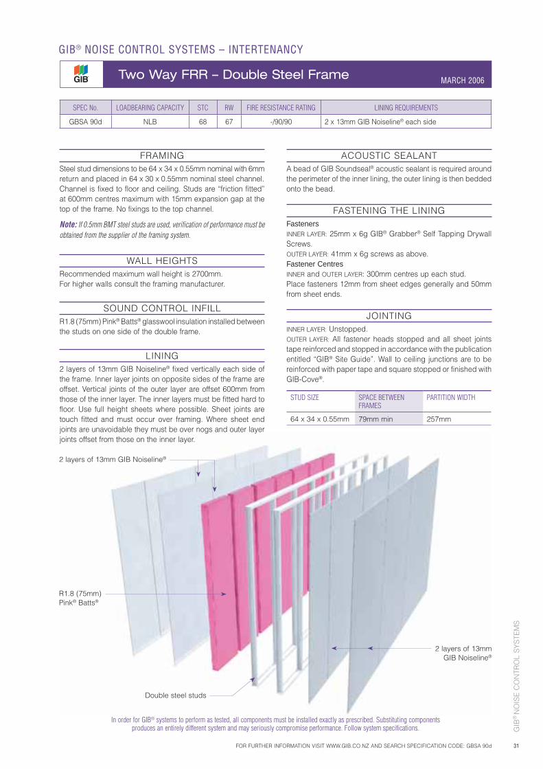
GIB
® N
OIS
E C
ON
TRO
L S
YS
TEM
S
31
2 layers of 13mm GIB Noiseline®
R1.8 (75mm) Pink® Batts®
In order for GIB® systems to perform as tested, all components must be installed exactly as prescribed. Substituting components produces an entirely different system and may seriously compromise performance. Follow system specifications.
SPEC No. LOADBEARING CAPACITY STC RW FIRE RESISTANCE RATING LINING REQUIREMENTS
GBSA 90d NLB 68 67 -/90/90 2 x 13mm GIB Noiseline® each side
FRAMINGSteel stud dimensions to be 64 x 34 x 0.55mm nominal with 6mm return and placed in 64 x 30 x 0.55mm nominal steel channel.Channel is fixed to floor and ceiling. Studs are “friction fitted” at 600mm centres maximum with 15mm expansion gap at the top of the frame. No fixings to the top channel.
Note: If 0.5mm BMT steel studs are used, verification of performance must be obtained from the supplier of the framing system.
WALL HEIGHTS Recommended maximum wall height is 2700mm. For higher walls consult the framing manufacturer.
SOUND CONTROL INFILLR1.8 (75mm) Pink® Batts® glasswool insulation installed between the studs on one side of the double frame.
LINING2 layers of 13mm GIB Noiseline® fixed vertically each side of the frame. Inner layer joints on opposite sides of the frame are offset. Vertical joints of the outer layer are offset 600mm from those of the inner layer. The inner layers must be fitted hard to floor. Use full height sheets where possible. Sheet joints are touch fitted and must occur over framing. Where sheet end joints are unavoidable they must be over nogs and outer layer joints offset from those on the inner layer.
ACOUSTIC SEALANTA bead of GIB Soundseal® acoustic sealant is required around the perimeter of the inner lining, the outer lining is then bedded onto the bead.
FASTENING THE LININGFastenersINNER LAYER: 25mm x 6g GIB® Grabber® Self Tapping Drywall Screws.OUTER LAYER: 41mm x 6g screws as above.Fastener CentresINNER and OUTER LAYER: 300mm centres up each stud.Place fasteners 12mm from sheet edges generally and 50mm from sheet ends.
JOINTINGINNER LAYER: Unstopped.OUTER LAYER: All fastener heads stopped and all sheet joints tape reinforced and stopped in accordance with the publication entitled “GIB® Site Guide”. Wall to ceiling junctions are to be reinforced with paper tape and square stopped or finished with GIB-Cove®.
STUD SIZE SPACE BETWEEN FRAMES
PARTITION WIDTH
64 x 34 x 0.55mm 79mm min 257mm
2 layers of 13mm GIB Noiseline®
Double steel studs
FOR FURTHER INFORMATION VISIT WWW.GIB.CO.NZ AND SEARCH SPECIFICATION CODE: GBSA 90d
GIB® NOISE CONTROL SYSTEMS – INTERTENANCY
Two Way FRR – Double Steel Frame MARCH 2006
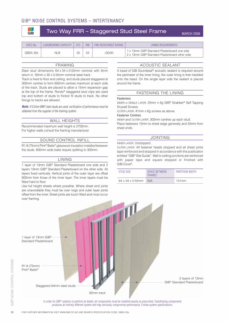
GIB
® N
OIS
E C
ON
TRO
L S
YS
TEM
S
32
1 layer of 13mm GIB® Standard Plasterboard
R1.8 (75mm) Pink® Batts®
Staggered 64mm steel studs
2 layers of 13mm GIB® Standard Plasterboard
92mm track
ACOUSTIC SEALANTA bead of GIB Soundseal® acoustic sealant is required around the perimeter of the inner lining, the outer lining is then bedded onto the bead. On the single layer side the sealant is placed around the frame.
FASTENING THE LININGFastenersINNER or SINGLE LAYER: 25mm x 6g GIB® Grabber® Self Tapping Drywall Screws.OUTER LAYER: 41mm x 6g screws as above.Fastener CentresINNER and OUTER LAYER: 300mm centres up each stud.Place fasteners 12mm to sheet edge generally and 50mm from sheet ends.
JOINTINGINNER LAYER: Unstopped.OUTER LAYER: All fastener heads stopped and all sheet joints tape reinforced and stopped in accordance with the publication entitled “GIB® Site Guide”. Wall to ceiling junctions are reinforced with paper tape and square stopped or finished with GIB-Cove®.
FRAMINGSteel stud dimensions 64 x 34 x 0.55mm nominal with 6mm return in 92mm x 30 x 0.55mm nominal steel track .Track is fixed to floor and ceiling, and studs placed staggered at 300mm centres to form 600mm centres maximum at each side of the track. Studs are placed to allow a 15mm expansion gap at the top of the frame. Rondo® staggered stud clips are used top and bottom of studs to friction fit studs to track. No other fixings to tracks are allowed.
Note: If 0.5mm BMT steel studs are used, verification of performance must be obtained from the supplier of the framing system.
WALL HEIGHTS Recommended maximum wall height is 2700mm. For higher walls consult the framing manufacturer.
SOUND CONTROL INFILLR1.8 (75mm) Pink® Batts® glasswool insulation installed between the studs. 600mm wide batts require splitting to 300mm.
LINING1 layer of 13mm GIB® Standard Plasterboard one side and 2 layers 13mm GIB® Standard Plasterboard on the other side. All layers fixed vertically. Vertical joints of the outer layer are offset 600mm from those of the inner layer. The inner layers must be fitted hard to floor.Use full height sheets where possible. Where sheet end joints are unavoidable they must be over nogs and outer layer joints offset from the inner. Sheet joints are touch fitted and must occur over framing.
SPEC No. LOADBEARING CAPACITY STC RW FIRE RESISTANCE RATING LINING REQUIREMENTS
GBSA 30s NLB 55 53 -/30/301 x 13mm GIB® Standard Plasterboard one side2 x 13mm GIB® Standard Plasterboard other side
STUD SIZE SPACE BETWEEN FRAMES
PARTITION WIDTH
64 x 34 x 0.55mm N/A 131mm
In order for GIB® systems to perform as tested, all components must be installed exactly as prescribed. Substituting components produces an entirely different system and may seriously compromise performance. Follow system specifications.
GIB® NOISE CONTROL SYSTEMS – INTERTENANCY
Two Way FRR – Staggered Stud Steel Frame MARCH 2006
FOR FURTHER INFORMATION VISIT WWW.GIB.CO.NZ AND SEARCH SPECIFICATION CODE: GBSA 30s
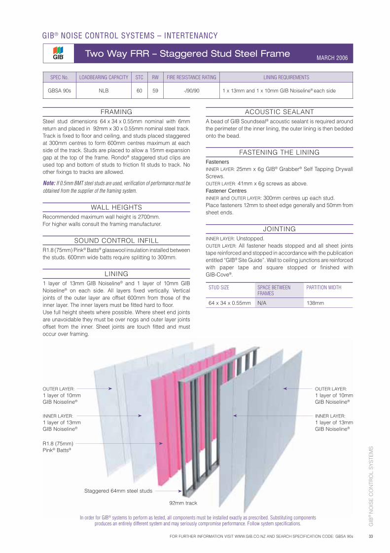
GIB
® N
OIS
E C
ON
TRO
L S
YS
TEM
S
33
In order for GIB® systems to perform as tested, all components must be installed exactly as prescribed. Substituting components produces an entirely different system and may seriously compromise performance. Follow system specifications.
SPEC No. LOADBEARING CAPACITY STC RW FIRE RESISTANCE RATING LINING REQUIREMENTS
GBSA 90s NLB 60 59 -/90/90 1 x 13mm and 1 x 10mm GIB Noiseline® each side
OUTER LAYER:1 layer of 10mm GIB Noiseline®
R1.8 (75mm) Pink® Batts®
Staggered 64mm steel studs
92mm track
ACOUSTIC SEALANTA bead of GIB Soundseal® acoustic sealant is required around the perimeter of the inner lining, the outer lining is then bedded onto the bead.
FASTENING THE LININGFastenersINNER LAYER: 25mm x 6g GIB® Grabber® Self Tapping Drywall Screws.OUTER LAYER: 41mm x 6g screws as above.Fastener CentresINNER and OUTER LAYER: 300mm centres up each stud.Place fasteners 12mm to sheet edge generally and 50mm from sheet ends.
JOINTINGINNER LAYER: Unstopped.OUTER LAYER: All fastener heads stopped and all sheet joints tape reinforced and stopped in accordance with the publication entitled “GIB® Site Guide”. Wall to ceiling junctions are reinforced with paper tape and square stopped or finished with GIB-Cove®.
FRAMINGSteel stud dimensions 64 x 34 x 0.55mm nominal with 6mm return and placed in 92mm x 30 x 0.55mm nominal steel track.Track is fixed to floor and ceiling, and studs placed staggered at 300mm centres to form 600mm centres maximum at each side of the track. Studs are placed to allow a 15mm expansion gap at the top of the frame. Rondo® staggered stud clips are used top and bottom of studs to friction fit studs to track. No other fixings to tracks are allowed.
Note: If 0.5mm BMT steel studs are used, verification of performance must be obtained from the supplier of the framing system.
WALL HEIGHTS Recommended maximum wall height is 2700mm. For higher walls consult the framing manufacturer.
SOUND CONTROL INFILLR1.8 (75mm) Pink® Batts® glasswool insulation installed between the studs. 600mm wide batts require splitting to 300mm.
LINING1 layer of 13mm GIB Noiseline® and 1 layer of 10mm GIB Noiseline® on each side. All layers fixed vertically. Vertical joints of the outer layer are offset 600mm from those of the inner layer. The inner layers must be fitted hard to floor.Use full height sheets where possible. Where sheet end joints are unavoidable they must be over nogs and outer layer joints offset from the inner. Sheet joints are touch fitted and must occur over framing.
STUD SIZE SPACE BETWEEN FRAMES
PARTITION WIDTH
64 x 34 x 0.55mm N/A 138mm
INNER LAYER:1 layer of 13mm GIB Noiseline®
OUTER LAYER:1 layer of 10mm GIB Noiseline®
INNER LAYER:1 layer of 13mm GIB Noiseline®
FOR FURTHER INFORMATION VISIT WWW.GIB.CO.NZ AND SEARCH SPECIFICATION CODE: GBSA 90s
GIB® NOISE CONTROL SYSTEMS – INTERTENANCY
Two Way FRR – Staggered Stud Steel Frame MARCH 2006
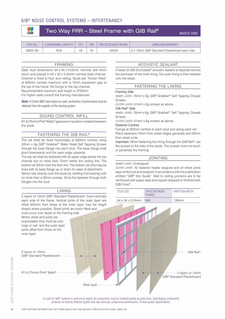
GIB
® N
OIS
E C
ON
TRO
L S
YS
TEM
S
34
FRAMINGSteel stud dimensions 64 x 34 x 0.55mm nominal with 6mm return and placed in 64 x 30 x 0.55mm nominal steel channel.Channel is fixed to floor and ceiling. Studs are “friction fitted” at 600mm centres maximum with a 15mm expansion gap at the top of the frame. No fixings to the top channel. Recommended maximum wall height is 2700mm. For higher walls consult the framing manufacturer.
Note: If 0.5mm BMT steel studs are used, verification of performance must be obtained from the supplier of the framing system.
SOUND CONTROL INFILLR1.8 (75mm) Pink® Batts® glasswool insulation installed between the studs.
FASTENING THE GIB RAIL®
The rail shall be fixed horizontally at 600mm centres using 32mm x 8g GIB® Grabber® Wafer Head Self Tapping Screws through the base flange into each stud. The base flange shall point downwards and the open edge upwards.The top rail shall be fastened with its upper edge below the top channel but no more than 75mm below the ceiling line. The bottom rail 50mm from the floor line. The bottom rail only may be fixed with its base flange up or down for ease of attachment.Splice rails directly over the studs by nestling (not butting) with no more than a 20mm overlap. Drive the fastener through both flanges into the stud.
LINING2 layers of 13mm GIB® Standard Plasterboard fixed vertically each side of the frame. Vertical joints of the outer layer are offset 600mm from those of the inner layer. Use full height sheets where possible. Sheet joints are touch fitted and must occur over studs on the framing side. Where sheet end joints are unavoidable they must be over nogs or nail and the outer layer joints offset from those on the inner layer.
ACOUSTIC SEALANTA bead of GIB Soundseal® acoustic sealant is required around the perimeter of the inner lining, the outer lining is then bedded onto the bead.
FASTENING THE LININGFraming SideINNER LAYER: 25mm x 6g GIB® Grabber® Self Tapping Drywall Screws. OUTER LAYER: 41mm x 6g screws as above.GIB Rail® SideINNER LAYER: 25mm x 6g GIB® Grabber® Self Tapping Drywall Screws.OUTER LAYER: 41mm x 6g screws as above.Fastener CentresFixings at 300mm centres to each stud and along each rail.Place fasteners 12mm from sheet edges generally and 50mm from sheet ends.Important: When fastening the lining through the GIB Rail®, set the screws to the side of the studs. The screws must not touch or penetrate the framing.
JOINTINGINNER LAYER: Unstopped.OUTER LAYER: All fastener heads stopped and all sheet joints tape reinforced and stopped in accordance with the publication entitled “GIB® Site Guide”. Wall to ceiling junctions are to be reinforced with paper tape and square stopped or finished with GIB-Cove®.
SPEC No. LOADBEARING CAPACITY STC RW FIRE RESISTANCE RATING LINING REQUIREMENTS
GBSA 30r NLB 55 55 -/30/30 2 x 13mm GIB® Standard Plasterboard each side
2 layers of 13mm GIB® Standard Plasterboard
2 layers of 13mm GIB® Standard Plasterboard
Steel stud
GIB Rail®
STUD SIZE SPACE BETWEEN FRAMES
PARTITION WIDTH
64 x 34 x 0.55mm N/A 128mm
R1.8 (75mm) Pink® Batts®
In order for GIB® systems to perform as tested, all components must be installed exactly as prescribed. Substituting components produces an entirely different system and may seriously compromise performance. Follow system specifications.
GIB® NOISE CONTROL SYSTEMS – INTERTENANCY
Two Way FRR – Steel Frame with GIB Rail® MARCH 2006
FOR FURTHER INFORMATION VISIT WWW.GIB.CO.NZ AND SEARCH SPECIFICATION CODE: GBSA 45r
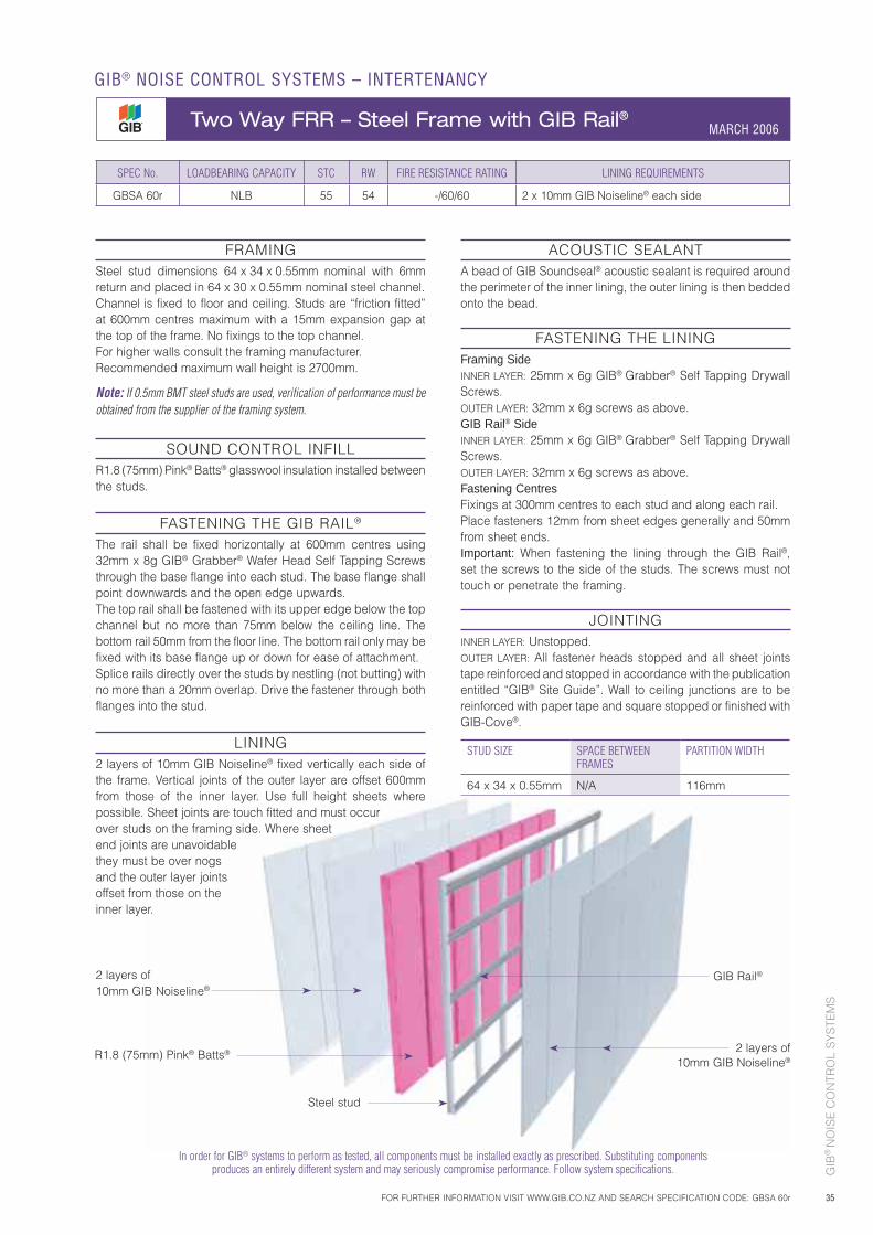
GIB
® N
OIS
E C
ON
TRO
L S
YS
TEM
S
35
FRAMINGSteel stud dimensions 64 x 34 x 0.55mm nominal with 6mm return and placed in 64 x 30 x 0.55mm nominal steel channel.Channel is fixed to floor and ceiling. Studs are “friction fitted” at 600mm centres maximum with a 15mm expansion gap at the top of the frame. No fixings to the top channel.For higher walls consult the framing manufacturer.Recommended maximum wall height is 2700mm.
Note: If 0.5mm BMT steel studs are used, verification of performance must be obtained from the supplier of the framing system.
SOUND CONTROL INFILLR1.8 (75mm) Pink® Batts® glasswool insulation installed between the studs.
FASTENING THE GIB RAIL®
The rail shall be fixed horizontally at 600mm centres using 32mm x 8g GIB® Grabber® Wafer Head Self Tapping Screws through the base flange into each stud. The base flange shall point downwards and the open edge upwards.The top rail shall be fastened with its upper edge below the top channel but no more than 75mm below the ceiling line. The bottom rail 50mm from the floor line. The bottom rail only may be fixed with its base flange up or down for ease of attachment.Splice rails directly over the studs by nestling (not butting) with no more than a 20mm overlap. Drive the fastener through both flanges into the stud.
LINING2 layers of 10mm GIB Noiseline® fixed vertically each side of the frame. Vertical joints of the outer layer are offset 600mm from those of the inner layer. Use full height sheets where possible. Sheet joints are touch fitted and must occur over studs on the framing side. Where sheet end joints are unavoidable they must be over nogs and the outer layer joints offset from those on the inner layer.
ACOUSTIC SEALANTA bead of GIB Soundseal® acoustic sealant is required around the perimeter of the inner lining, the outer lining is then bedded onto the bead.
FASTENING THE LININGFraming SideINNER LAYER: 25mm x 6g GIB® Grabber® Self Tapping Drywall Screws. OUTER LAYER: 32mm x 6g screws as above.GIB Rail® SideINNER LAYER: 25mm x 6g GIB® Grabber® Self Tapping Drywall Screws.OUTER LAYER: 32mm x 6g screws as above.Fastening CentresFixings at 300mm centres to each stud and along each rail.Place fasteners 12mm from sheet edges generally and 50mm from sheet ends.Important: When fastening the lining through the GIB Rail®, set the screws to the side of the studs. The screws must not touch or penetrate the framing.
JOINTINGINNER LAYER: Unstopped.OUTER LAYER: All fastener heads stopped and all sheet joints tape reinforced and stopped in accordance with the publication entitled “GIB® Site Guide”. Wall to ceiling junctions are to be reinforced with paper tape and square stopped or finished with GIB-Cove®.
STUD SIZE SPACE BETWEEN FRAMES
PARTITION WIDTH
64 x 34 x 0.55mm N/A 116mm
SPEC No. LOADBEARING CAPACITY STC RW FIRE RESISTANCE RATING LINING REQUIREMENTS
GBSA 60r NLB 55 54 -/60/60 2 x 10mm GIB Noiseline® each side
2 layers of 10mm GIB Noiseline®
2 layers of 10mm GIB Noiseline®
Steel stud
GIB Rail®
R1.8 (75mm) Pink® Batts®
In order for GIB® systems to perform as tested, all components must be installed exactly as prescribed. Substituting components produces an entirely different system and may seriously compromise performance. Follow system specifications.
FOR FURTHER INFORMATION VISIT WWW.GIB.CO.NZ AND SEARCH SPECIFICATION CODE: GBSA 60r
GIB® NOISE CONTROL SYSTEMS – INTERTENANCY
Two Way FRR – Steel Frame with GIB Rail® MARCH 2006
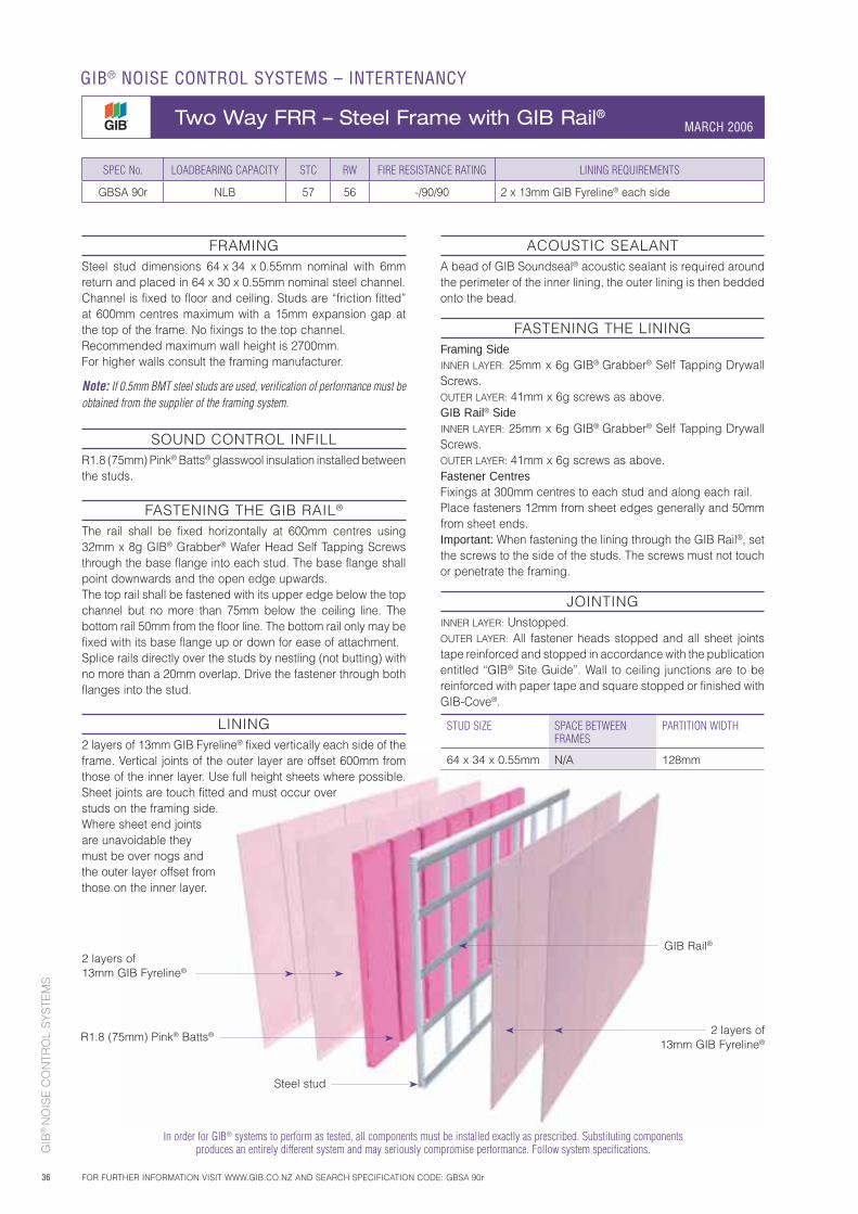
GIB
® N
OIS
E C
ON
TRO
L S
YS
TEM
S
36
FRAMINGSteel stud dimensions 64 x 34 x 0.55mm nominal with 6mm return and placed in 64 x 30 x 0.55mm nominal steel channel.Channel is fixed to floor and ceiling. Studs are “friction fitted” at 600mm centres maximum with a 15mm expansion gap at the top of the frame. No fixings to the top channel.Recommended maximum wall height is 2700mm. For higher walls consult the framing manufacturer.
Note: If 0.5mm BMT steel studs are used, verification of performance must be obtained from the supplier of the framing system.
SOUND CONTROL INFILLR1.8 (75mm) Pink® Batts® glasswool insulation installed between the studs.
FASTENING THE GIB RAIL®
The rail shall be fixed horizontally at 600mm centres using 32mm x 8g GIB® Grabber® Wafer Head Self Tapping Screws through the base flange into each stud. The base flange shall point downwards and the open edge upwards.The top rail shall be fastened with its upper edge below the top channel but no more than 75mm below the ceiling line. The bottom rail 50mm from the floor line. The bottom rail only may be fixed with its base flange up or down for ease of attachment.Splice rails directly over the studs by nestling (not butting) with no more than a 20mm overlap. Drive the fastener through both flanges into the stud.
LINING2 layers of 13mm GIB Fyreline® fixed vertically each side of the frame. Vertical joints of the outer layer are offset 600mm from those of the inner layer. Use full height sheets where possible. Sheet joints are touch fitted and must occur over studs on the framing side. Where sheet end joints are unavoidable they must be over nogs and the outer layer offset from those on the inner layer.
ACOUSTIC SEALANTA bead of GIB Soundseal® acoustic sealant is required around the perimeter of the inner lining, the outer lining is then bedded onto the bead.
FASTENING THE LININGFraming SideINNER LAYER: 25mm x 6g GIB® Grabber® Self Tapping Drywall Screws. OUTER LAYER: 41mm x 6g screws as above.GIB Rail® SideINNER LAYER: 25mm x 6g GIB® Grabber® Self Tapping Drywall Screws.OUTER LAYER: 41mm x 6g screws as above.Fastener CentresFixings at 300mm centres to each stud and along each rail.Place fasteners 12mm from sheet edges generally and 50mm from sheet ends.Important: When fastening the lining through the GIB Rail®, set the screws to the side of the studs. The screws must not touch or penetrate the framing.
JOINTINGINNER LAYER: Unstopped.OUTER LAYER: All fastener heads stopped and all sheet joints tape reinforced and stopped in accordance with the publication entitled “GIB® Site Guide”. Wall to ceiling junctions are to be reinforced with paper tape and square stopped or finished with GIB-Cove®.
STUD SIZE SPACE BETWEEN FRAMES
PARTITION WIDTH
64 x 34 x 0.55mm N/A 128mm
SPEC No. LOADBEARING CAPACITY STC RW FIRE RESISTANCE RATING LINING REQUIREMENTS
GBSA 90r NLB 57 56 -/90/90 2 x 13mm GIB Fyreline® each side
In order for GIB® systems to perform as tested, all components must be installed exactly as prescribed. Substituting components produces an entirely different system and may seriously compromise performance. Follow system specifications.
2 layers of 13mm GIB Fyreline®
2 layers of 13mm GIB Fyreline®
Steel stud
GIB Rail®
R1.8 (75mm) Pink® Batts®
GIB® NOISE CONTROL SYSTEMS – INTERTENANCY
Two Way FRR – Steel Frame with GIB Rail® MARCH 2006
FOR FURTHER INFORMATION VISIT WWW.GIB.CO.NZ AND SEARCH SPECIFICATION CODE: GBSA 90r
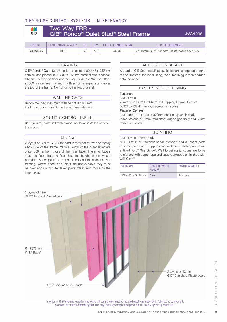
GIB
® N
OIS
E C
ON
TRO
L S
YS
TEM
S
37
SPEC No. LOADBEARING CAPACITY STC RW FIRE RESISTANCE RATING LINING REQUIREMENTS
GBQSA 45 NLB 56 56 -/45/45 2 x 13mm GIB® Standard Plasterboard each side
In order for GIB® systems to perform as tested, all components must be installed exactly as prescribed. Substituting components produces an entirely different system and may seriously compromise performance. Follow system specifications.
FRAMINGGIB® Rondo® Quiet Stud® resilient steel stud 92 x 45 x 0.55mm nominal and placed in 92 x 30 x 0.55mm nominal steel channel.Channel is fixed to floor and ceiling. Studs are “friction fitted” at 600mm centres maximum with a 15mm expansion gap at the top of the frame. No fixings to the top channel.
WALL HEIGHTS Recommended maximum wall height is 3600mm. For higher walls consult the framing manufacturer.
SOUND CONTROL INFILLR1.8 (75mm) Pink® Batts® glasswool insulation installed between the studs.
LINING2 layers of 13mm GIB® Standard Plasterboard fixed vertically each side of the frame. Vertical joints of the outer layer are offset 600mm from those of the inner layer. The inner layers must be fitted hard to floor. Use full height sheets where possible. Sheet joints are touch fitted and must occur over framing. Where sheet end joints are unavoidable they must be over nogs and outer layer joints offset from those on the inner layer.
ACOUSTIC SEALANTA bead of GIB Soundseal® acoustic sealant is required around the perimeter of the inner lining, the outer lining is then bedded onto the bead.
FASTENING THE LININGFastenersINNER LAYER: 25mm x 6g GIB® Grabber® Self Tapping Drywall Screws.OUTER LAYER: 41mm x 6g screws as above.Fastener CentresINNER and OUTER LAYER: 300mm centres up each stud.Place fasteners 12mm from sheet edges generally and 50mm from sheet ends.
JOINTINGINNER LAYER: Unstopped.OUTER LAYER: All fastener heads stopped and all sheet joints tape reinforced and stopped in accordance with the publication entitled “GIB® Site Guide”. Wall to ceiling junctions are to be reinforced with paper tape and square stopped or finished with GIB-Cove®.
STUD SIZE SPACE BETWEEN FRAMES
PARTITION WIDTH
92 x 45 x 0.55mm N/A 144mm
2 layers of 13mm GIB® Standard Plasterboard
2 layers of 13mm GIB® Standard Plasterboard
GIB® Rondo® Quiet Stud®
R1.8 (75mm) Pink® Batts®
FOR FURTHER INFORMATION VISIT WWW.GIB.CO.NZ AND SEARCH SPECIFICATION CODE: GBQSA 45
GIB® NOISE CONTROL SYSTEMS – INTERTENANCY
Two Way FRR – GIB® Rondo® Quiet Stud® Steel Frame MARCH 2006
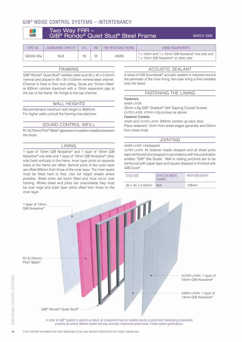
GIB
® N
OIS
E C
ON
TRO
L S
YS
TEM
S
38
1 layer of 13mm GIB Noiseline®
OUTER LAYER: 1 layer of 10mm GIB Noiseline®
R1.8 (75mm) Pink® Batts®
SPEC No. LOADBEARING CAPACITY STC RW FIRE RESISTANCE RATING LINING REQUIREMENTS
GBQSA 60a NLB 56 55 -/60/601 x 13mm and 1 x 10mm GIB Noiseline® one side and1 x 13mm GIB Noiseline® on other side
In order for GIB® systems to perform as tested, all components must be installed exactly as prescribed. Substituting components produces an entirely different system and may seriously compromise performance. Follow system specifications.
FRAMINGGIB® Rondo® Quiet Stud® resilient steel stud 92 x 45 x 0.55mm nominal and placed in 92 x 30 x 0.55mm nominal steel channel.Channel is fixed to floor and ceiling. Studs are “friction fitted” at 600mm centres maximum with a 15mm expansion gap at the top of the frame. No fixings to the top channel.
WALL HEIGHTS Recommended maximum wall height is 3600mm. For higher walls consult the framing manufacturer.
SOUND CONTROL INFILLR1.8 (75mm) Pink® Batts® glasswool insulation installed between the studs.
LINING1 layer of 13mm GIB Noiseline® and 1 layer of 10mm GIB Noiseline® one side and 1 layer of 13mm GIB Noiseline® other side fixed vertically to the frame. Inner layer joints on opposite sides of the frame are offset. Vertical joints of the outer layer are offset 600mm from those of the inner layer. The inner layers must be fitted hard to floor. Use full height sheets where possible. Sheet joints are touch fitted and must occur over framing. Where sheet end joints are unavoidable they must be over nogs and outer layer joints offset from those on the inner layer.
ACOUSTIC SEALANTA bead of GIB Soundseal® acoustic sealant is required around the perimeter of the inner lining, the outer lining is then bedded onto the bead.
FASTENING THE LININGFastenersINNER LAYER: 25mm x 6g GIB® Grabber® Self Tapping Drywall Screws.OUTER LAYER: 41mm x 6g screws as above.Fastener CentresINNER and OUTER LAYER: 300mm centres up each stud.Place fasteners 12mm from sheet edges generally and 50mm from sheet ends.
JOINTINGINNER LAYER: Unstopped.OUTER LAYER: All fastener heads stopped and all sheet joints tape reinforced and stopped in accordance with the publication entitled “GIB® Site Guide”. Wall to ceiling junctions are to be reinforced with paper tape and square stopped or finished with GIB-Cove®.
STUD SIZE SPACE BETWEEN FRAMES
PARTITION WIDTH
92 x 45 x 0.55mm N/A 128mm
GIB® Rondo® Quiet Stud®
INNER LAYER: 1 layer of 13mm GIB Noiseline®
GIB® NOISE CONTROL SYSTEMS – INTERTENANCY
Two Way FRR – GIB® Rondo® Quiet Stud® Steel Frame MARCH 2006
FOR FURTHER INFORMATION VISIT WWW.GIB.CO.NZ AND SEARCH SPECIFICATION CODE: GBQSA 60a
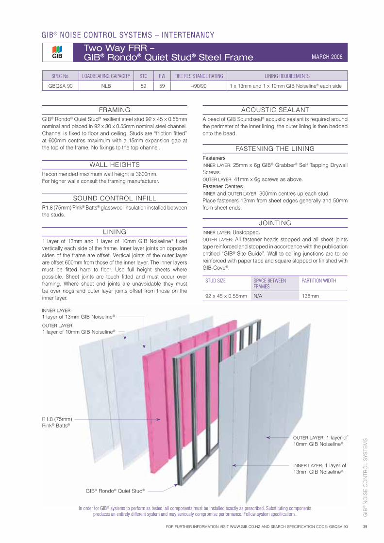
GIB
® N
OIS
E C
ON
TRO
L S
YS
TEM
S
39
INNER LAYER:1 layer of 13mm GIB Noiseline®
R1.8 (75mm) Pink® Batts®
SPEC No. LOADBEARING CAPACITY STC RW FIRE RESISTANCE RATING LINING REQUIREMENTS
GBQSA 90 NLB 59 59 -/90/90 1 x 13mm and 1 x 10mm GIB Noiseline® each side
FRAMINGGIB® Rondo® Quiet Stud® resilient steel stud 92 x 45 x 0.55mm nominal and placed in 92 x 30 x 0.55mm nominal steel channel.Channel is fixed to floor and ceiling. Studs are “friction fitted” at 600mm centres maximum with a 15mm expansion gap at the top of the frame. No fixings to the top channel.
WALL HEIGHTS Recommended maximum wall height is 3600mm. For higher walls consult the framing manufacturer.
SOUND CONTROL INFILLR1.8 (75mm) Pink® Batts® glasswool insulation installed between the studs.
LINING1 layer of 13mm and 1 layer of 10mm GIB Noiseline® fixed vertically each side of the frame. Inner layer joints on opposite sides of the frame are offset. Vertical joints of the outer layer are offset 600mm from those of the inner layer. The inner layers must be fitted hard to floor. Use full height sheets where possible. Sheet joints are touch fitted and must occur over framing. Where sheet end joints are unavoidable they must be over nogs and outer layer joints offset from those on the inner layer.
ACOUSTIC SEALANTA bead of GIB Soundseal® acoustic sealant is required around the perimeter of the inner lining, the outer lining is then bedded onto the bead.
FASTENING THE LININGFastenersINNER LAYER: 25mm x 6g GIB® Grabber® Self Tapping Drywall Screws.OUTER LAYER: 41mm x 6g screws as above.Fastener CentresINNER and OUTER LAYER: 300mm centres up each stud.Place fasteners 12mm from sheet edges generally and 50mm from sheet ends.
JOINTINGINNER LAYER: Unstopped.OUTER LAYER: All fastener heads stopped and all sheet joints tape reinforced and stopped in accordance with the publication entitled “GIB® Site Guide”. Wall to ceiling junctions are to be reinforced with paper tape and square stopped or finished with GIB-Cove®.
STUD SIZE SPACE BETWEEN FRAMES
PARTITION WIDTH
92 x 45 x 0.55mm N/A 138mm
In order for GIB® systems to perform as tested, all components must be installed exactly as prescribed. Substituting components produces an entirely different system and may seriously compromise performance. Follow system specifications.
GIB® Rondo® Quiet Stud®
OUTER LAYER: 1 layer of 10mm GIB Noiseline®
INNER LAYER: 1 layer of 13mm GIB Noiseline®
OUTER LAYER:1 layer of 10mm GIB Noiseline®
FOR FURTHER INFORMATION VISIT WWW.GIB.CO.NZ AND SEARCH SPECIFICATION CODE: GBQSA 90
GIB® NOISE CONTROL SYSTEMS – INTERTENANCY
Two Way FRR – GIB® Rondo® Quiet Stud® Steel Frame MARCH 2006
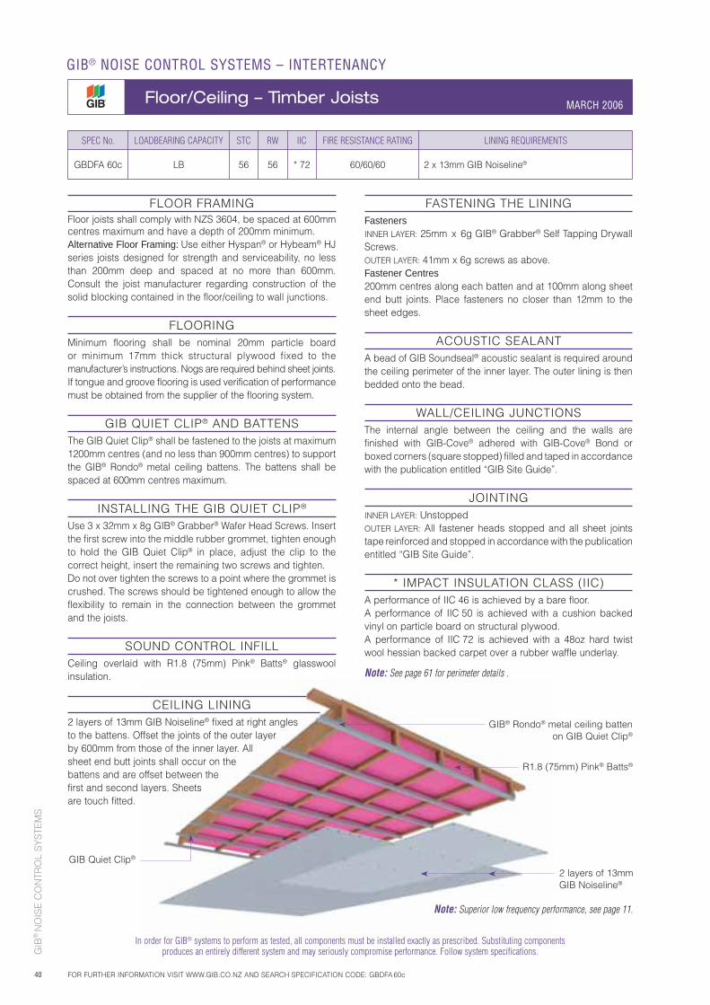
GIB
® N
OIS
E C
ON
TRO
L S
YS
TEM
S
40
In order for GIB® systems to perform as tested, all components must be installed exactly as prescribed. Substituting components produces an entirely different system and may seriously compromise performance. Follow system specifications.
FLOOR FRAMINGFloor joists shall comply with NZS 3604, be spaced at 600mm centres maximum and have a depth of 200mm minimum.Alternative Floor Framing: Use either Hyspan® or Hybeam® HJ series joists designed for strength and serviceability, no less than 200mm deep and spaced at no more than 600mm. Consult the joist manufacturer regarding construction of the solid blocking contained in the floor/ceiling to wall junctions.
FLOORINGMinimum flooring shall be nominal 20mm particle board or minimum 17mm thick structural plywood fixed to the manufacturer’s instructions. Nogs are required behind sheet joints. If tongue and groove flooring is used verification of performance must be obtained from the supplier of the flooring system.
GIB QUIET CLIP® AND BATTENSThe GIB Quiet Clip® shall be fastened to the joists at maximum 1200mm centres (and no less than 900mm centres) to support the GIB® Rondo® metal ceiling battens. The battens shall be spaced at 600mm centres maximum.
INSTALLING THE GIB QUIET CLIP®
Use 3 x 32mm x 8g GIB® Grabber® Wafer Head Screws. Insert the first screw into the middle rubber grommet, tighten enough to hold the GIB Quiet Clip® in place, adjust the clip to the correct height, insert the remaining two screws and tighten.Do not over tighten the screws to a point where the grommet is crushed. The screws should be tightened enough to allow the flexibility to remain in the connection between the grommet and the joists.
SOUND CONTROL INFILLCeiling overlaid with R1.8 (75mm) Pink® Batts® glasswool insulation.
CEILING LINING2 layers of 13mm GIB Noiseline® fixed at right angles to the battens. Offset the joints of the outer layer by 600mm from those of the inner layer. All sheet end butt joints shall occur on the battens and are offset between the first and second layers. Sheets are touch fitted.
FASTENING THE LININGFastenersINNER LAYER: 25mm x 6g GIB® Grabber® Self Tapping Drywall Screws.OUTER LAYER: 41mm x 6g screws as above.Fastener Centres200mm centres along each batten and at 100mm along sheet end butt joints. Place fasteners no closer than 12mm to the sheet edges.
ACOUSTIC SEALANTA bead of GIB Soundseal® acoustic sealant is required around the ceiling perimeter of the inner layer. The outer lining is then bedded onto the bead.
WALL/CEILING JUNCTIONSThe internal angle between the ceiling and the walls are finished with GIB-Cove® adhered with GIB-Cove® Bond or boxed corners (square stopped) filled and taped in accordance with the publication entitled “GIB Site Guide”.
JOINTINGINNER LAYER: UnstoppedOUTER LAYER: All fastener heads stopped and all sheet joints tape reinforced and stopped in accordance with the publication entitled “GIB Site Guide”.
* IMPACT INSULATION CLASS (IIC)A performance of IIC 46 is achieved by a bare floor.A performance of IIC 50 is achieved with a cushion backed vinyl on particle board on structural plywood.A performance of IIC 72 is achieved with a 48oz hard twist wool hessian backed carpet over a rubber waffle underlay.
Note: See page 61 for perimeter details .
SPEC No. LOADBEARING CAPACITY STC RW IIC FIRE RESISTANCE RATING LINING REQUIREMENTS
GBDFA 60c LB 56 56 * 72 60/60/60 2 x 13mm GIB Noiseline®
GIB Quiet Clip®
R1.8 (75mm) Pink® Batts®
2 layers of 13mm GIB Noiseline®
GIB® NOISE CONTROL SYSTEMS – INTERTENANCY
Floor/Ceiling – Timber Joists MARCH 2006
FOR FURTHER INFORMATION VISIT WWW.GIB.CO.NZ AND SEARCH SPECIFICATION CODE: GBDFA 60c
GIB® Rondo® metal ceiling batten on GIB Quiet Clip®
Note: Superior low frequency performance, see page 11.
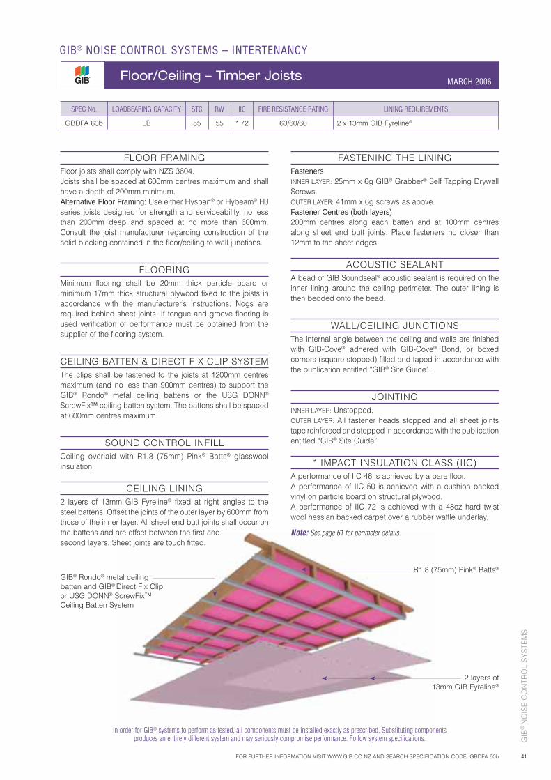
GIB
® N
OIS
E C
ON
TRO
L S
YS
TEM
S
41
FLOOR FRAMINGFloor joists shall comply with NZS 3604.Joists shall be spaced at 600mm centres maximum and shall have a depth of 200mm minimum.Alternative Floor Framing: Use either Hyspan® or Hybeam® HJ series joists designed for strength and serviceability, no less than 200mm deep and spaced at no more than 600mm. Consult the joist manufacturer regarding construction of the solid blocking contained in the floor/ceiling to wall junctions.
FLOORINGMinimum flooring shall be 20mm thick particle board or minimum 17mm thick structural plywood fixed to the joists in accordance with the manufacturer’s instructions. Nogs are required behind sheet joints. If tongue and groove flooring is used verification of performance must be obtained from the supplier of the flooring system.
CEILING BATTEN & DIRECT FIX CLIP SYSTEMThe clips shall be fastened to the joists at 1200mm centres maximum (and no less than 900mm centres) to support the GIB® Rondo® metal ceiling battens or the USG DONN® ScrewFix™ ceiling batten system. The battens shall be spaced at 600mm centres maximum.
SOUND CONTROL INFILLCeiling overlaid with R1.8 (75mm) Pink® Batts® glasswool insulation.
CEILING LINING2 layers of 13mm GIB Fyreline® fixed at right angles to the steel battens. Offset the joints of the outer layer by 600mm from those of the inner layer. All sheet end butt joints shall occur on the battens and are offset between the first and second layers. Sheet joints are touch fitted.
FASTENING THE LININGFastenersINNER LAYER: 25mm x 6g GIB® Grabber® Self Tapping Drywall Screws.OUTER LAYER: 41mm x 6g screws as above.Fastener Centres (both layers)200mm centres along each batten and at 100mm centres along sheet end butt joints. Place fasteners no closer than 12mm to the sheet edges.
ACOUSTIC SEALANTA bead of GIB Soundseal® acoustic sealant is required on the inner lining around the ceiling perimeter. The outer lining is then bedded onto the bead.
WALL/CEILING JUNCTIONSThe internal angle between the ceiling and walls are finished with GIB-Cove® adhered with GIB-Cove® Bond, or boxed corners (square stopped) filled and taped in accordance with the publication entitled “GIB® Site Guide”.
JOINTINGINNER LAYER: Unstopped.OUTER LAYER: All fastener heads stopped and all sheet joints tape reinforced and stopped in accordance with the publication entitled “GIB® Site Guide”.
* IMPACT INSULATION CLASS (IIC)A performance of IIC 46 is achieved by a bare floor.A performance of IIC 50 is achieved with a cushion backed vinyl on particle board on structural plywood.A performance of IIC 72 is achieved with a 48oz hard twist wool hessian backed carpet over a rubber waffle underlay.
Note: See page 61 for perimeter details.
SPEC No. LOADBEARING CAPACITY STC RW IIC FIRE RESISTANCE RATING LINING REQUIREMENTS
GBDFA 60b LB 55 55 * 72 60/60/60 2 x 13mm GIB Fyreline®
R1.8 (75mm) Pink® Batts®
2 layers of 13mm GIB Fyreline®
GIB® Rondo® metal ceiling batten and GIB® Direct Fix Clip or USG DONN® ScrewFix™ Ceiling Batten System
In order for GIB® systems to perform as tested, all components must be installed exactly as prescribed. Substituting components produces an entirely different system and may seriously compromise performance. Follow system specifications.
FOR FURTHER INFORMATION VISIT WWW.GIB.CO.NZ AND SEARCH SPECIFICATION CODE: GBDFA 60b
GIB® NOISE CONTROL SYSTEMS – INTERTENANCY
Floor/Ceiling – Timber Joists MARCH 2006
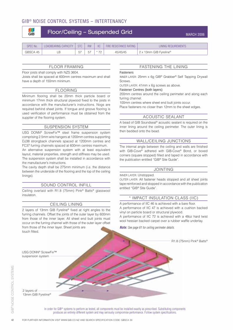
GIB
® N
OIS
E C
ON
TRO
L S
YS
TEM
S
42
FLOOR FRAMINGFloor joists shall comply with NZS 3604.Joists shall be spaced at 600mm centres maximum and shall have a depth of 150mm minimum.
FLOORINGMinimum flooring shall be 20mm thick particle board or minimum 17mm thick structural plywood fixed to the joists in accordance with the manufacturer’s instructions. Nogs are required behind sheet joints. If tongue and groove flooring is used verification of performance must be obtained from the supplier of the flooring system.
SUSPENSION SYSTEMUSG DONN® ScrewFix™ steel frame suspension system comprising 2.5mm wire hangers at 1200mm centres supporting DJ38 strongback channels spaced at 1200mm centres and FC37 furring channels spaced at 600mm centres maximum.An alternative suspension system with at least equivalent layout, material properties, strength and stiffness may be used.The suspension system shall be installed in accordance with the manufacturer’s instructions.The cavity depth shall be 275mm minimum (i.e. the distance between the underside of the flooring and the top of the ceiling linings).
SOUND CONTROL INFILLCeiling overlaid with R1.8 (75mm) Pink® Batts® glasswool insulation.
CEILING LINING2 layers of 13mm GIB Fyreline® fixed at right angles to the furring channels. Offset the joints of the outer layer by 600mm from those of the inner layer. All sheet end butt joints must occur on the furring channel with those of the outer layer offset from those of the inner layer. Sheet joints are touch fitted.
FASTENING THE LININGFastenersINNER LAYER: 25mm x 6g GIB® Grabber® Self Tapping Drywall Screws.OUTER LAYER: 41mm x 6g screws as above.Fastener Centres (both layers)200mm centres around the ceiling perimeter and along each furring channel.100mm centres where sheet end butt joints occur.Place fasteners no closer than 12mm to the sheet edges.
ACOUSTIC SEALANTA bead of GIB Soundseal® acoustic sealant is required on the inner lining around the ceiling perimeter. The outer lining is then bedded onto the bead.
WALL/CEILING JUNCTIONSThe internal angle between the ceiling and walls are finished with GIB-Cove® adhered with GIB-Cove® Bond, or boxed corners (square stopped) filled and taped in accordance with the publication entitled “GIB® Site Guide”.
JOINTINGINNER LAYER: Unstopped.OUTER LAYER: All fastener heads stopped and all sheet joints tape reinforced and stopped in accordance with the publication entitled “GIB® Site Guide”.
* IMPACT INSULATION CLASS (IIC)A performance of IIC 46 is achieved with a bare floor.A performance of IIC 47 is achieved with a cushion backed vinyl on particle board or structural plywood.A performance of IIC 72 is achieved with a 48oz hard twist wool hessian backed carpet over a rubber waffle underlay.
Note: See page 61 for ceiling perimeter details.
SPEC No. LOADBEARING CAPACITY STC RW IIC FIRE RESISTANCE RATING LINING REQUIREMENTS
GBSCA 45 LB 57 57 * 72 45/45/45 2 x 13mm GIB Fyreline®
USG DONN® ScrewFix™suspension system
R1.8 (75mm) Pink® Batts®
2 layers of 13mm GIB Fyreline®
In order for GIB® systems to perform as tested, all components must be installed exactly as prescribed. Substituting components produces an entirely different system and may seriously compromise performance. Follow system specifications.
GIB® NOISE CONTROL SYSTEMS – INTERTENANCY
Floor/Ceiling – Suspended Grid MARCH 2006
FOR FURTHER INFORMATION VISIT WWW.GIB.CO.NZ AND SEARCH SPECIFICATION CODE: GBSCA 30
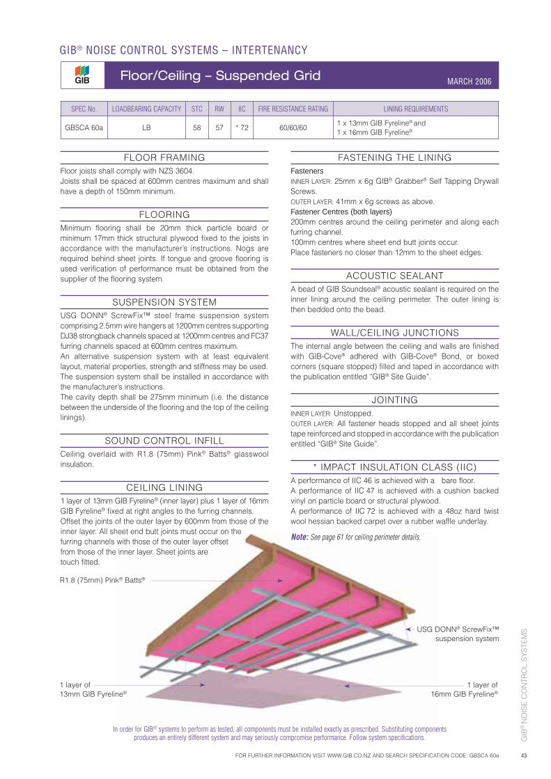
GIB
® N
OIS
E C
ON
TRO
L S
YS
TEM
S
43
FLOOR FRAMINGFloor joists shall comply with NZS 3604.Joists shall be spaced at 600mm centres maximum and shall have a depth of 150mm minimum.
FLOORINGMinimum flooring shall be 20mm thick particle board or minimum 17mm thick structural plywood fixed to the joists in accordance with the manufacturer’s instructions. Nogs are required behind sheet joints. If tongue and groove flooring is used verification of performance must be obtained from the supplier of the flooring system.
SUSPENSION SYSTEMUSG DONN® ScrewFix™ steel frame suspension system comprising 2.5mm wire hangers at 1200mm centres supporting DJ38 strongback channels spaced at 1200mm centres and FC37 furring channels spaced at 600mm centres maximum.An alternative suspension system with at least equivalent layout, material properties, strength and stiffness may be used.The suspension system shall be installed in accordance with the manufacturer’s instructions.The cavity depth shall be 275mm minimum (i.e. the distance between the underside of the flooring and the top of the ceiling linings).
SOUND CONTROL INFILLCeiling overlaid with R1.8 (75mm) Pink® Batts® glasswool insulation.
CEILING LINING1 layer of 13mm GIB Fyreline® (inner layer) plus 1 layer of 16mm GIB Fyreline® fixed at right angles to the furring channels.Offset the joints of the outer layer by 600mm from those of the inner layer. All sheet end butt joints must occur on the furring channels with those of the outer layer offset from those of the inner layer. Sheet joints are touch fitted.
FASTENING THE LININGFastenersINNER LAYER: 25mm x 6g GIB® Grabber® Self Tapping Drywall Screws.OUTER LAYER: 41mm x 6g screws as above.Fastener Centres (both layers)200mm centres around the ceiling perimeter and along each furring channel.100mm centres where sheet end butt joints occur.Place fasteners no closer than 12mm to the sheet edges.
ACOUSTIC SEALANTA bead of GIB Soundseal® acoustic sealant is required on the inner lining around the ceiling perimeter. The outer lining is then bedded onto the bead.
WALL/CEILING JUNCTIONSThe internal angle between the ceiling and walls are finished with GIB-Cove® adhered with GIB-Cove® Bond, or boxed corners (square stopped) filled and taped in accordance with the publication entitled “GIB® Site Guide”.
JOINTINGINNER LAYER: Unstopped.OUTER LAYER: All fastener heads stopped and all sheet joints tape reinforced and stopped in accordance with the publication entitled “GIB® Site Guide”.
* IMPACT INSULATION CLASS (IIC)A performance of IIC 46 is achieved with a bare floor.A performance of IIC 47 is achieved with a cushion backed vinyl on particle board or structural plywood.A performance of IIC 72 is achieved with a 48oz hard twist wool hessian backed carpet over a rubber waffle underlay.
Note: See page 61 for ceiling perimeter details.
SPEC No. LOADBEARING CAPACITY STC RW IIC FIRE RESISTANCE RATING LINING REQUIREMENTS
GBSCA 60a LB 58 57 * 72 60/60/601 x 13mm GIB Fyreline® and1 x 16mm GIB Fyreline®
R1.8 (75mm) Pink® Batts®
1 layer of 16mm GIB Fyreline®
In order for GIB® systems to perform as tested, all components must be installed exactly as prescribed. Substituting components produces an entirely different system and may seriously compromise performance. Follow system specifications.
1 layer of 13mm GIB Fyreline®
FOR FURTHER INFORMATION VISIT WWW.GIB.CO.NZ AND SEARCH SPECIFICATION CODE: GBSCA 60a
GIB® NOISE CONTROL SYSTEMS – INTERTENANCY
Floor/Ceiling – Suspended Grid MARCH 2006
USG DONN® ScrewFix™ suspension system
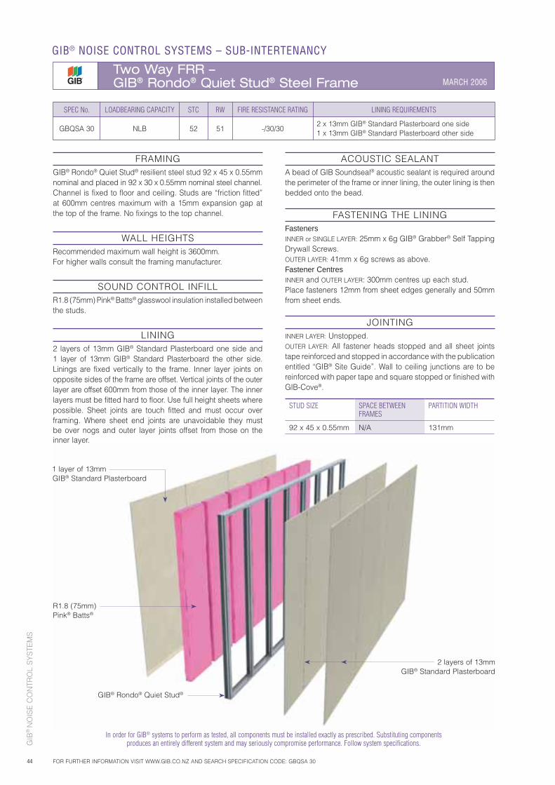
GIB
® N
OIS
E C
ON
TRO
L S
YS
TEM
S
44
In order for GIB® systems to perform as tested, all components must be installed exactly as prescribed. Substituting components produces an entirely different system and may seriously compromise performance. Follow system specifications.
SPEC No. LOADBEARING CAPACITY STC RW FIRE RESISTANCE RATING LINING REQUIREMENTS
GBQSA 30 NLB 52 51 -/30/302 x 13mm GIB® Standard Plasterboard one side1 x 13mm GIB® Standard Plasterboard other side
FRAMINGGIB® Rondo® Quiet Stud® resilient steel stud 92 x 45 x 0.55mm nominal and placed in 92 x 30 x 0.55mm nominal steel channel.Channel is fixed to floor and ceiling. Studs are “friction fitted” at 600mm centres maximum with a 15mm expansion gap at the top of the frame. No fixings to the top channel.
WALL HEIGHTS Recommended maximum wall height is 3600mm. For higher walls consult the framing manufacturer.
SOUND CONTROL INFILLR1.8 (75mm) Pink® Batts® glasswool insulation installed between the studs.
LINING2 layers of 13mm GIB® Standard Plasterboard one side and 1 layer of 13mm GIB® Standard Plasterboard the other side. Linings are fixed vertically to the frame. Inner layer joints on opposite sides of the frame are offset. Vertical joints of the outer layer are offset 600mm from those of the inner layer. The inner layers must be fitted hard to floor. Use full height sheets where possible. Sheet joints are touch fitted and must occur over framing. Where sheet end joints are unavoidable they must be over nogs and outer layer joints offset from those on the inner layer.
ACOUSTIC SEALANTA bead of GIB Soundseal® acoustic sealant is required around the perimeter of the frame or inner lining, the outer lining is then bedded onto the bead.
FASTENING THE LININGFastenersINNER or SINGLE LAYER: 25mm x 6g GIB® Grabber® Self Tapping Drywall Screws.OUTER LAYER: 41mm x 6g screws as above.Fastener CentresINNER and OUTER LAYER: 300mm centres up each stud.Place fasteners 12mm from sheet edges generally and 50mm from sheet ends.
JOINTINGINNER LAYER: Unstopped.OUTER LAYER: All fastener heads stopped and all sheet joints tape reinforced and stopped in accordance with the publication entitled “GIB® Site Guide”. Wall to ceiling junctions are to be reinforced with paper tape and square stopped or finished with GIB-Cove®.
STUD SIZE SPACE BETWEEN FRAMES
PARTITION WIDTH
92 x 45 x 0.55mm N/A 131mm
1 layer of 13mm GIB® Standard Plasterboard
R1.8 (75mm) Pink® Batts®
2 layers of 13mm GIB® Standard Plasterboard
GIB® Rondo® Quiet Stud®
GIB® NOISE CONTROL SYSTEMS – SUB-INTERTENANCY
Two Way FRR – GIB® Rondo® Quiet Stud® Steel Frame MARCH 2006
FOR FURTHER INFORMATION VISIT WWW.GIB.CO.NZ AND SEARCH SPECIFICATION CODE: GBQSA 30
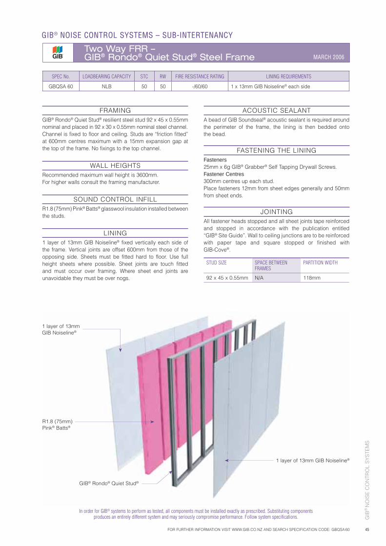
GIB
® N
OIS
E C
ON
TRO
L S
YS
TEM
S
45
SPEC No. LOADBEARING CAPACITY STC RW FIRE RESISTANCE RATING LINING REQUIREMENTS
GBQSA 60 NLB 50 50 -/60/60 1 x 13mm GIB Noiseline® each side
ACOUSTIC SEALANTA bead of GIB Soundseal® acoustic sealant is required around the perimeter of the frame, the lining is then bedded onto the bead.
FASTENING THE LININGFasteners25mm x 6g GIB® Grabber® Self Tapping Drywall Screws.Fastener Centres300mm centres up each stud.Place fasteners 12mm from sheet edges generally and 50mm from sheet ends.
JOINTINGAll fastener heads stopped and all sheet joints tape reinforced and stopped in accordance with the publication entitled “GIB® Site Guide”. Wall to ceiling junctions are to be reinforced with paper tape and square stopped or finished with GIB-Cove®.
In order for GIB® systems to perform as tested, all components must be installed exactly as prescribed. Substituting components produces an entirely different system and may seriously compromise performance. Follow system specifications.
1 layer of 13mm GIB Noiseline®
R1.8 (75mm) Pink® Batts®
1 layer of 13mm GIB Noiseline®
GIB® Rondo® Quiet Stud®
FRAMINGGIB® Rondo® Quiet Stud® resilient steel stud 92 x 45 x 0.55mm nominal and placed in 92 x 30 x 0.55mm nominal steel channel.Channel is fixed to floor and ceiling. Studs are “friction fitted” at 600mm centres maximum with a 15mm expansion gap at the top of the frame. No fixings to the top channel.
WALL HEIGHTS Recommended maximum wall height is 3600mm. For higher walls consult the framing manufacturer.
SOUND CONTROL INFILLR1.8 (75mm) Pink® Batts® glasswool insulation installed between the studs.
LINING1 layer of 13mm GIB Noiseline® fixed vertically each side of the frame. Vertical joints are offset 600mm from those of the opposing side. Sheets must be fitted hard to floor. Use full height sheets where possible. Sheet joints are touch fitted and must occur over framing. Where sheet end joints are unavoidable they must be over nogs.
STUD SIZE SPACE BETWEEN FRAMES
PARTITION WIDTH
92 x 45 x 0.55mm N/A 118mm
FOR FURTHER INFORMATION VISIT WWW.GIB.CO.NZ AND SEARCH SPECIFICATION CODE: GBQSA 60
GIB® NOISE CONTROL SYSTEMS – SUB-INTERTENANCY
Two Way FRR – GIB® Rondo® Quiet Stud® Steel Frame MARCH 2006
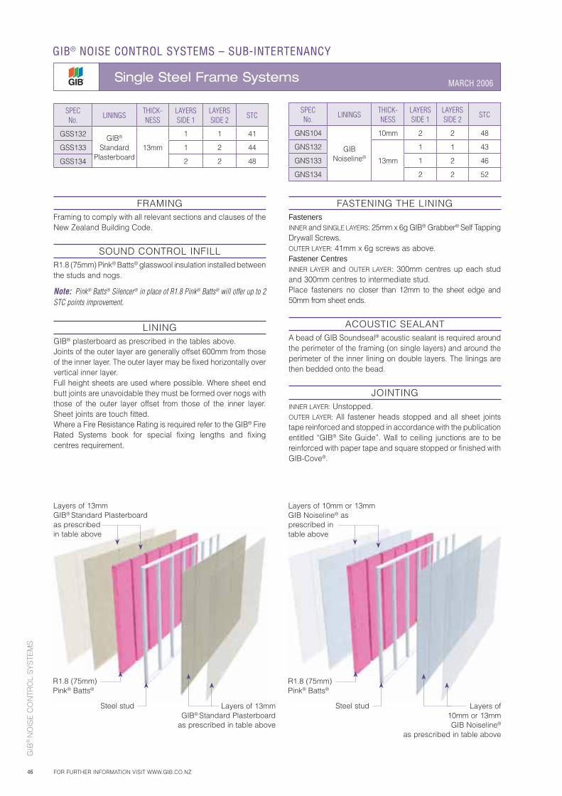
GIB
® N
OIS
E C
ON
TRO
L S
YS
TEM
S
46
FASTENING THE LININGFastenersINNER and SINGLE LAYERS: 25mm x 6g GIB® Grabber® Self Tapping Drywall Screws.OUTER LAYER: 41mm x 6g screws as above.Fastener CentresINNER LAYER and OUTER LAYER: 300mm centres up each stud and 300mm centres to intermediate stud. Place fasteners no closer than 12mm to the sheet edge and 50mm from sheet ends.
ACOUSTIC SEALANTA bead of GIB Soundseal® acoustic sealant is required around the perimeter of the framing (on single layers) and around the perimeter of the inner lining on double layers. The linings are then bedded onto the bead.
JOINTINGINNER LAYER: Unstopped.OUTER LAYER: All fastener heads stopped and all sheet joints tape reinforced and stopped in accordance with the publication entitled “GIB® Site Guide”. Wall to ceiling junctions are to be reinforced with paper tape and square stopped or finished with GIB-Cove®.
FRAMINGFraming to comply with all relevant sections and clauses of the New Zealand Building Code.
SOUND CONTROL INFILLR1.8 (75mm) Pink® Batts® glasswool insulation installed between the studs and nogs.
Note: Pink® Batts® Silencer® in place of R1.8 Pink® Batts® will offer up to 2 STC points improvement.
LININGGIB® plasterboard as prescribed in the tables above.Joints of the outer layer are generally offset 600mm from those of the inner layer. The outer layer may be fixed horizontally over vertical inner layer.Full height sheets are used where possible. Where sheet end butt joints are unavoidable they must be formed over nogs with those of the outer layer offset from those of the inner layer. Sheet joints are touch fitted.Where a Fire Resistance Rating is required refer to the GIB® Fire Rated Systems book for special fixing lengths and fixing centres requirement.
SPECNo.
LININGSTHICK-NESS
LAYERSSIDE 1
LAYERSSIDE 2
STC
GSS132 GIB® Standard
Plasterboard13mm
1 1 41
GSS133 1 2 44
GSS134 2 2 48
SPECNo.
LININGSTHICK-NESS
LAYERSSIDE 1
LAYERSSIDE 2
STC
GNS104
GIBNoiseline®
10mm 2 2 48
GNS132
13mm
1 1 43
GNS133 1 2 46
GNS134 2 2 52
GIB® NOISE CONTROL SYSTEMS – SUB-INTERTENANCY
Single Steel Frame Systems MARCH 2006
FOR FURTHER INFORMATION VISIT WWW.GIB.CO.NZ
Layers of 13mm GIB® Standard Plasterboard as prescribed in table above
R1.8 (75mm) Pink® Batts®
Steel stud
Layers of 10mm or 13mm GIB Noiseline® asprescribed intable above
Layers of 13mm GIB® Standard Plasterboard
as prescribed in table above
Layers of 10mm or 13mm GIB Noiseline®
as prescribed in table above
R1.8 (75mm) Pink® Batts®
Steel stud
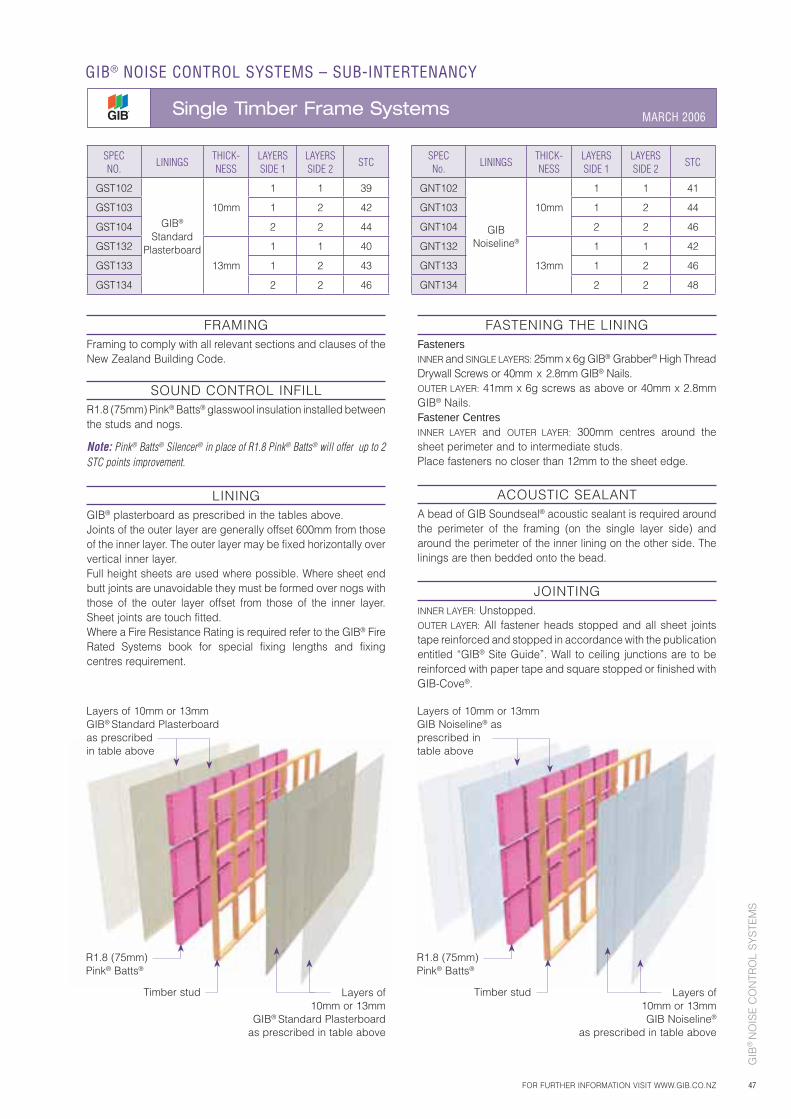
GIB
® N
OIS
E C
ON
TRO
L S
YS
TEM
S
47
FASTENING THE LININGFastenersINNER and SINGLE LAYERS: 25mm x 6g GIB® Grabber® High Thread Drywall Screws or 40mm x 2.8mm GIB® Nails.OUTER LAYER: 41mm x 6g screws as above or 40mm x 2.8mm GIB® Nails.Fastener CentresINNER LAYER and OUTER LAYER: 300mm centres around the sheet perimeter and to intermediate studs.Place fasteners no closer than 12mm to the sheet edge.
ACOUSTIC SEALANTA bead of GIB Soundseal® acoustic sealant is required around the perimeter of the framing (on the single layer side) and around the perimeter of the inner lining on the other side. The linings are then bedded onto the bead.
JOINTINGINNER LAYER: Unstopped.OUTER LAYER: All fastener heads stopped and all sheet joints tape reinforced and stopped in accordance with the publication entitled “GIB® Site Guide”. Wall to ceiling junctions are to be reinforced with paper tape and square stopped or finished with GIB-Cove®.
FRAMINGFraming to comply with all relevant sections and clauses of the New Zealand Building Code.
SOUND CONTROL INFILLR1.8 (75mm) Pink® Batts® glasswool insulation installed between the studs and nogs.
Note: Pink® Batts® Silencer® in place of R1.8 Pink® Batts® will offer up to 2 STC points improvement.
LININGGIB® plasterboard as prescribed in the tables above.Joints of the outer layer are generally offset 600mm from those of the inner layer. The outer layer may be fixed horizontally over vertical inner layer.Full height sheets are used where possible. Where sheet end butt joints are unavoidable they must be formed over nogs with those of the outer layer offset from those of the inner layer. Sheet joints are touch fitted.Where a Fire Resistance Rating is required refer to the GIB® Fire Rated Systems book for special fixing lengths and fixing centres requirement.
SPECNO.
LININGSTHICK-NESS
LAYERSSIDE 1
LAYERSSIDE 2
STC
GST102
GIB® Standard
Plasterboard
10mm
1 1 39
GST103 1 2 42
GST104 2 2 44
GST132
13mm
1 1 40
GST133 1 2 43
GST134 2 2 46
SPECNo.
LININGSTHICK-NESS
LAYERSSIDE 1
LAYERSSIDE 2
STC
GNT102
GIBNoiseline®
10mm
1 1 41
GNT103 1 2 44
GNT104 2 2 46
GNT132
13mm
1 1 42
GNT133 1 2 46
GNT134 2 2 48
FOR FURTHER INFORMATION VISIT WWW.GIB.CO.NZ
GIB® NOISE CONTROL SYSTEMS – SUB-INTERTENANCY
Single Timber Frame Systems MARCH 2006
R1.8 (75mm) Pink® Batts®
Timber stud Layers of 10mm or 13mm
GIB® Standard Plasterboardas prescribed in table above
Layers of 10mm or 13mm GIB Noiseline®
as prescribed in table above
R1.8 (75mm) Pink® Batts®
Timber stud
Layers of 10mm or 13mm GIB® Standard Plasterboardas prescribedin table above
Layers of 10mm or 13mm GIB Noiseline® asprescribed intable above
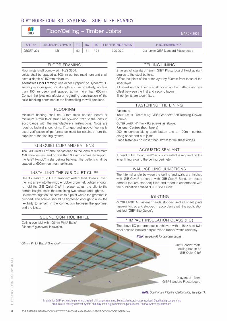
GIB
® N
OIS
E C
ON
TRO
L S
YS
TEM
S
48
FLOOR FRAMINGFloor joists shall comply with NZS 3604.Joists shall be spaced at 600mm centres maximum and shall have a depth of 150mm minimum.Alternative Floor Framing: Use either Hyspan® or Hybeam® HJ series joists designed for strength and serviceability, no less than 150mm deep and spaced at no more than 600mm. Consult the joist manufacturer regarding construction of the solid blocking contained in the floor/ceiling to wall junctions.
FLOORINGMinimum flooring shall be 20mm thick particle board or minimum 17mm thick structural plywood fixed to the joists in accordance with the manufacturer’s instructions. Nogs are required behind sheet joints. If tongue and groove flooring is used verification of performance must be obtained from the supplier of the flooring system.
GIB QUIET CLIP® AND BATTENSThe GIB Quiet Clip® shall be fastened to the joists at maximum 1200mm centres (and no less than 900mm centres) to support the GIB® Rondo® metal ceiling battens. The battens shall be spaced at 600mm centres maximum.
INSTALLING THE GIB QUIET CLIP®
Use 3 x 32mm x 8g GIB® Grabber® Wafer Head Screws. Insert the first screw into the middle rubber grommet, tighten enough to hold the GIB Quiet Clip® in place, adjust the clip to the correct height, insert the remaining two screws and tighten.Do not over tighten the screws to a point where the grommet is crushed. The screws should be tightened enough to allow the flexibility to remain in the connection between the grommet and the joists.
SOUND CONTROL INFILLCeiling overlaid with 100mm Pink® Batts® Silencer® glasswool insulation.
CEILING LINING2 layers of standard 13mm GIB® Plasterboard fixed at right angles to the steel battens.Offset the joints of the outer layer by 600mm from those of the inner layer.All sheet end butt joints shall occur on the battens and are offset between the first and second layers.Sheet joints are touch fitted.
FASTENING THE LININGFastenersINNER LAYER: 25mm x 6g GIB® Grabber® Self Tapping Drywall Screws.OUTER LAYER: 41mm x 6g screws as above.Fastener Centres (both layers)200mm centres along each batten and at 100mm centres along sheet end butt joints.Place fasteners no closer than 12mm to the sheet edges.
ACOUSTIC SEALANTA bead of GIB Soundseal® acoustic sealant is required on the inner lining around the ceiling perimeter.
WALL/CEILING JUNCTIONSThe internal angle between the ceiling and walls are finished with GIB-Cove® adhered with GIB-Cove® Bond, or boxed corners (square stopped) filled and taped in accordance with the publication entitled “GIB® Site Guide”.
JOINTINGOUTER LAYER: All fastener heads stopped and all sheet joints tape reinforced and stopped in accordance with the publication entitled “GIB® Site Guide”.
* IMPACT INSULATION CLASS (IIC)The above IIC performance is achieved with a 48oz hard twist wool hessian backed carpet over a rubber waffle underlay.
Note: See page 61 for perimeter details .
SPEC No. LOADBEARING CAPACITY STC RW IIC FIRE RESISTANCE RATING LINING REQUIREMENTS
GBDFA 30a LB 52 51 * 71 30/30/30 2 x 13mm GIB® Standard Plasterboard
100mm Pink® Batts® Silencer®
2 layers of 13mm GIB® Standard Plasterboard
GIB® Rondo® metal ceiling batten on GIB Quiet Clip®
In order for GIB® systems to perform as tested, all components must be installed exactly as prescribed. Substituting components produces an entirely different system and may seriously compromise performance. Follow system specifications.
GIB® NOISE CONTROL SYSTEMS – SUB-INTERTENANCY
MARCH 2006
FOR FURTHER INFORMATION VISIT WWW.GIB.CO.NZ AND SEARCH SPECIFICATION CODE: GBDFA 30a
Floor/Ceiling – Timber Joists
Note: Superior low frequency performance, see page 11.
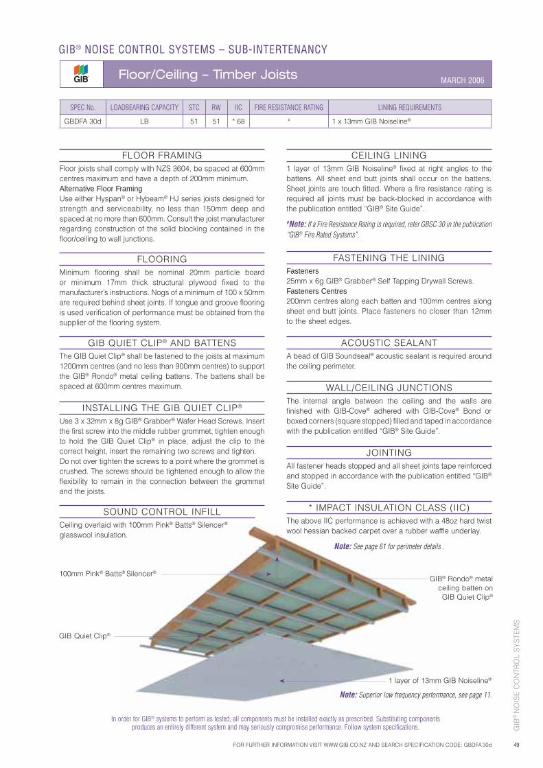
GIB
® N
OIS
E C
ON
TRO
L S
YS
TEM
S
49
In order for GIB® systems to perform as tested, all components must be installed exactly as prescribed. Substituting components produces an entirely different system and may seriously compromise performance. Follow system specifications.
FLOOR FRAMINGFloor joists shall comply with NZS 3604, be spaced at 600mm centres maximum and have a depth of 200mm minimum.Alternative Floor FramingUse either Hyspan® or Hybeam® HJ series joists designed for strength and serviceability, no less than 150mm deep and spaced at no more than 600mm. Consult the joist manufacturer regarding construction of the solid blocking contained in the floor/ceiling to wall junctions.
FLOORINGMinimum flooring shall be nominal 20mm particle board or minimum 17mm thick structural plywood fixed to the manufacturer’s instructions. Nogs of a minimum of 100 x 50mm are required behind sheet joints. If tongue and groove flooring is used verification of performance must be obtained from the supplier of the flooring system.
GIB QUIET CLIP® AND BATTENSThe GIB Quiet Clip® shall be fastened to the joists at maximum 1200mm centres (and no less than 900mm centres) to support the GIB® Rondo® metal ceiling battens. The battens shall be spaced at 600mm centres maximum.
INSTALLING THE GIB QUIET CLIP®
Use 3 x 32mm x 8g GIB® Grabber® Wafer Head Screws. Insert the first screw into the middle rubber grommet, tighten enough to hold the GIB Quiet Clip® in place, adjust the clip to the correct height, insert the remaining two screws and tighten.Do not over tighten the screws to a point where the grommet is crushed. The screws should be tightened enough to allow the flexibility to remain in the connection between the grommet and the joists.
SOUND CONTROL INFILLCeiling overlaid with 100mm Pink® Batts® Silencer® glasswool insulation.
CEILING LINING1 layer of 13mm GIB Noiseline® fixed at right angles to the battens. All sheet end butt joints shall occur on the battens. Sheet joints are touch fitted. Where a fire resistance rating is required all joints must be back-blocked in accordance with the publication entitled “GIB® Site Guide”.
#Note: If a Fire Resistance Rating is required, refer GBSC 30 in the publication “GIB® Fire Rated Systems”.
FASTENING THE LININGFasteners25mm x 6g GIB® Grabber® Self Tapping Drywall Screws.Fasteners Centres200mm centres along each batten and 100mm centres along sheet end butt joints. Place fasteners no closer than 12mm to the sheet edges.
ACOUSTIC SEALANTA bead of GIB Soundseal® acoustic sealant is required around the ceiling perimeter.
WALL/CEILING JUNCTIONSThe internal angle between the ceiling and the walls are finished with GIB-Cove® adhered with GIB-Cove® Bond or boxed corners (square stopped) filled and taped in accordance with the publication entitled “GIB® Site Guide”.
JOINTINGAll fastener heads stopped and all sheet joints tape reinforced and stopped in accordance with the publication entitled “GIB® Site Guide”.
* IMPACT INSULATION CLASS (IIC)The above IIC performance is achieved with a 48oz hard twist wool hessian backed carpet over a rubber waffle underlay.
Note: See page 61 for perimeter details .
SPEC No. LOADBEARING CAPACITY STC RW IIC FIRE RESISTANCE RATING LINING REQUIREMENTS
GBDFA 30d LB 51 51 * 68 # 1 x 13mm GIB Noiseline®
GIB Quiet Clip®
100mm Pink® Batts® Silencer®
1 layer of 13mm GIB Noiseline®
FOR FURTHER INFORMATION VISIT WWW.GIB.CO.NZ AND SEARCH SPECIFICATION CODE: GBDFA 30d
GIB® NOISE CONTROL SYSTEMS – SUB-INTERTENANCY
Floor/Ceiling – Timber Joists MARCH 2006
Note: Superior low frequency performance, see page 11.
GIB® Rondo® metal ceiling batten on GIB Quiet Clip®
GIB
® N
OIS
E C
ON
TRO
L S
YS
TEM
S
50
SPECIFIC DESIGNThe design information set out in this literature is necessarily generalised and only applicable to normal situations. Specific acoustic design advice should be sought from an experienced acoustical engineer in less common situations. For instance, inner city apartment developments of more than 5 storeys would usually benefit from specific design since even minor optimisation in construction can result in appreciable cost reductions. Specific design is also required where a residential development is located in a business or industrial zone and a specified internal noise level must be achieved for compliance with a building consent. The information given in this publication is based on normal free flowing traffic as the noise source and different types of noise could change the noise reduction values given. In particular this information should not be used where the noise source is loud or amplified music. Specific design is required in this case.
VARIATION IN SOUND RATINGSThe ability of building materials to resist the transmission of sound is dependent on their density, thickness and stiffness. Generally speaking light and stiff materials have poor sound insulation properties because they allow sound at certain frequencies (near the so-called critical frequency) to transmit easily. Materials of similar thickness and weight can have different sound reduction performance if they have different critical frequencies. For example, laminated glass has a better sound reduction because it reduces the effect of the critical frequency by damping vibration and reducing the stiffness of the window.
MULTI-STOREY BUILDINGSIn multi-storey buildings typical of apartment developments there are fewer transmission paths than traditional, single occupant, single level houses. For instance in the case of a bedroom on a mid level there will be no significant external noise transmission through the roof or the floor since these are shielded by the apartments above and below. Because there are fewer transmission paths the overall noise reduction is greater than a house with roof and floor paths. This factor can be included in the design by using the partial system performances detailed on pages 52, 53 and 54 (types A, B and C construction). Thus for the apartment with only a wall and window path the performance is about 3 dBA higher than the overall system performance. Multi-storey buildings do not often use weatherboards as an external cladding. However, 6mm fibre cement board can be used as an equivalent to 20mm weatherboards. It should be noted that the noise level does not reduce significantly with height in multi-storey buildings even up to 30 stories and so the same construction must be used on all levels.
WINDOW TO WALL RATIOThere is no optimum window to wall ratio. Generally speaking from an acoustic point of view the smaller the window the better since it is often the weakest path and thicker glazing or double glazing is more expensive in comparison to other building systems. The newer types of laminated glazing using a PMM interlayer (e.g. Pilkington HUSH Glass) provide about a 3 dBA improvement over similar thickness float glass. A 3 dBA reduction would otherwise require an increase from say 6mm to 10mm float glass.
ASSUMPTIONS IN DESIGNThe major assumption in design is that the noise spectrum is a traffic noise spectrum. The noise reduction may be a little more for industrial noise which generally has more mid to high frequency and less for low frequency dominated noises such as pubs or night-clubs etc. Another significant assumption is that windows are perfectly sealed. This is a reasonable assumption for aluminium joinery but a poor assumption for timber joinery. We would not recommend standard timber joinery for any noise reduction application above standard construction. Also all design assumes closed windows. Open windows will generally lower the noise reduction to between 10 and 15 dBA.
Fibre cement board (6mm) can be used as an equivalent to 20mm weatherboards. However, if a brick veneer is specified a slightly higher dBA loss can be expected.
Noise levels quoted are average levels. These are Leq for traffic noise, Ldn for aircraft noise and L10 for industrial noise.
GIB® NOISE CONTROL SYSTEMS
Environmental Noise MARCH 2006
FOR FURTHER INFORMATION VISIT WWW.GIB.CO.NZ
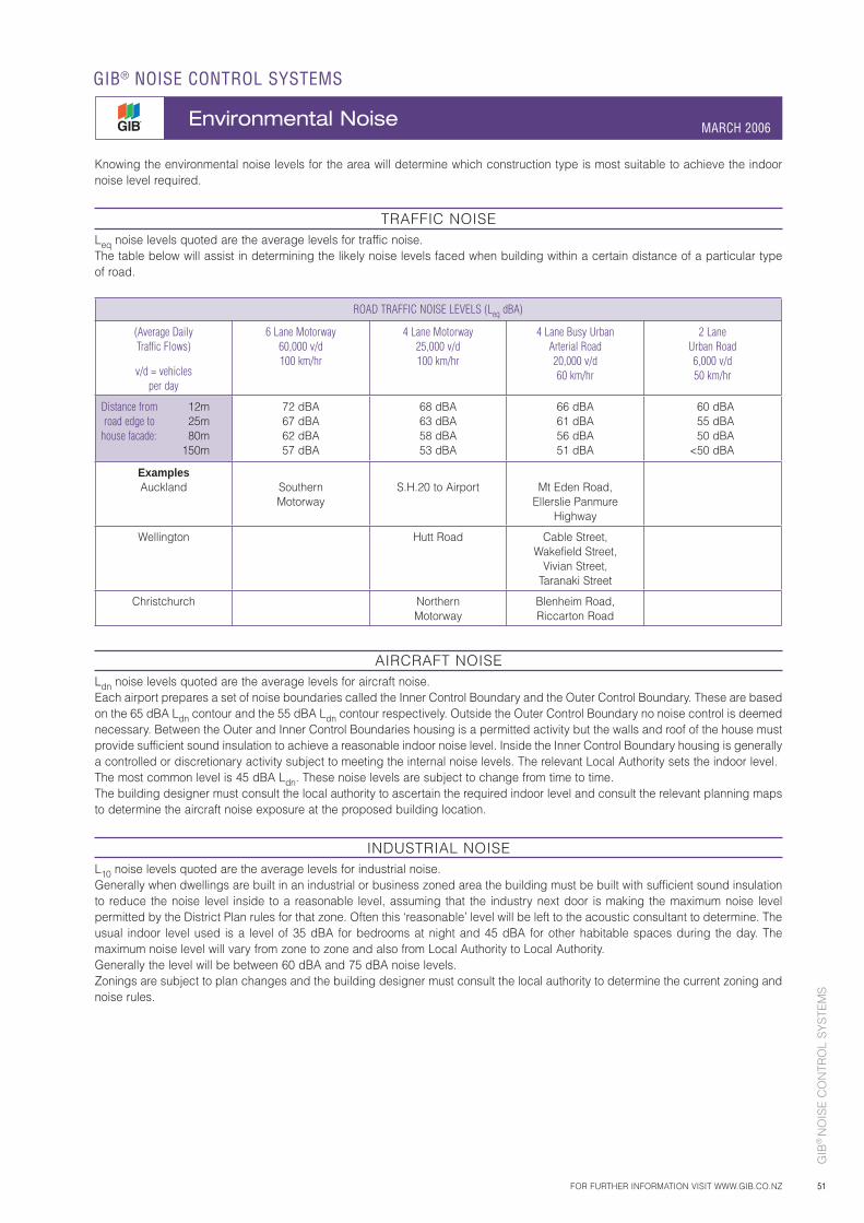
51
Knowing the environmental noise levels for the area will determine which construction type is most suitable to achieve the indoor noise level required.
TRAFFIC NOISELeq noise levels quoted are the average levels for traffic noise.The table below will assist in determining the likely noise levels faced when building within a certain distance of a particular type of road.
ROAD TRAFFIC NOISE LEVELS (Leq dBA)
(Average DailyTraffic Flows)
v/d = vehiclesper day
6 Lane Motorway60,000 v/d100 km/hr
4 Lane Motorway25,000 v/d100 km/hr
4 Lane Busy UrbanArterial Road20,000 v/d60 km/hr
2 LaneUrban Road6,000 v/d50 km/hr
Distance from road edge to
house facade:
12m25m80m
150m
72 dBA67 dBA62 dBA57 dBA
68 dBA63 dBA58 dBA53 dBA
66 dBA61 dBA56 dBA51 dBA
60 dBA 55 dBA 50 dBA <50 dBA
ExamplesAuckland Southern
MotorwayS.H.20 to Airport Mt Eden Road,
Ellerslie PanmureHighway
Wellington Hutt Road Cable Street,Wakefield Street,
Vivian Street,Taranaki Street
Christchurch NorthernMotorway
Blenheim Road,Riccarton Road
AIRCRAFT NOISELdn noise levels quoted are the average levels for aircraft noise.Each airport prepares a set of noise boundaries called the Inner Control Boundary and the Outer Control Boundary. These are based on the 65 dBA Ldn contour and the 55 dBA Ldn contour respectively. Outside the Outer Control Boundary no noise control is deemed necessary. Between the Outer and Inner Control Boundaries housing is a permitted activity but the walls and roof of the house must provide sufficient sound insulation to achieve a reasonable indoor noise level. Inside the Inner Control Boundary housing is generally a controlled or discretionary activity subject to meeting the internal noise levels. The relevant Local Authority sets the indoor level.The most common level is 45 dBA Ldn. These noise levels are subject to change from time to time.The building designer must consult the local authority to ascertain the required indoor level and consult the relevant planning maps to determine the aircraft noise exposure at the proposed building location.
INDUSTRIAL NOISEL10 noise levels quoted are the average levels for industrial noise.Generally when dwellings are built in an industrial or business zoned area the building must be built with sufficient sound insulation to reduce the noise level inside to a reasonable level, assuming that the industry next door is making the maximum noise level permitted by the District Plan rules for that zone. Often this ‘reasonable’ level will be left to the acoustic consultant to determine. The usual indoor level used is a level of 35 dBA for bedrooms at night and 45 dBA for other habitable spaces during the day. The maximum noise level will vary from zone to zone and also from Local Authority to Local Authority.Generally the level will be between 60 dBA and 75 dBA noise levels.Zonings are subject to plan changes and the building designer must consult the local authority to determine the current zoning and noise rules.
GIB
® N
OIS
E C
ON
TRO
L S
YS
TEM
S
FOR FURTHER INFORMATION VISIT WWW.GIB.CO.NZ
GIB® NOISE CONTROL SYSTEMS
Environmental Noise MARCH 2006
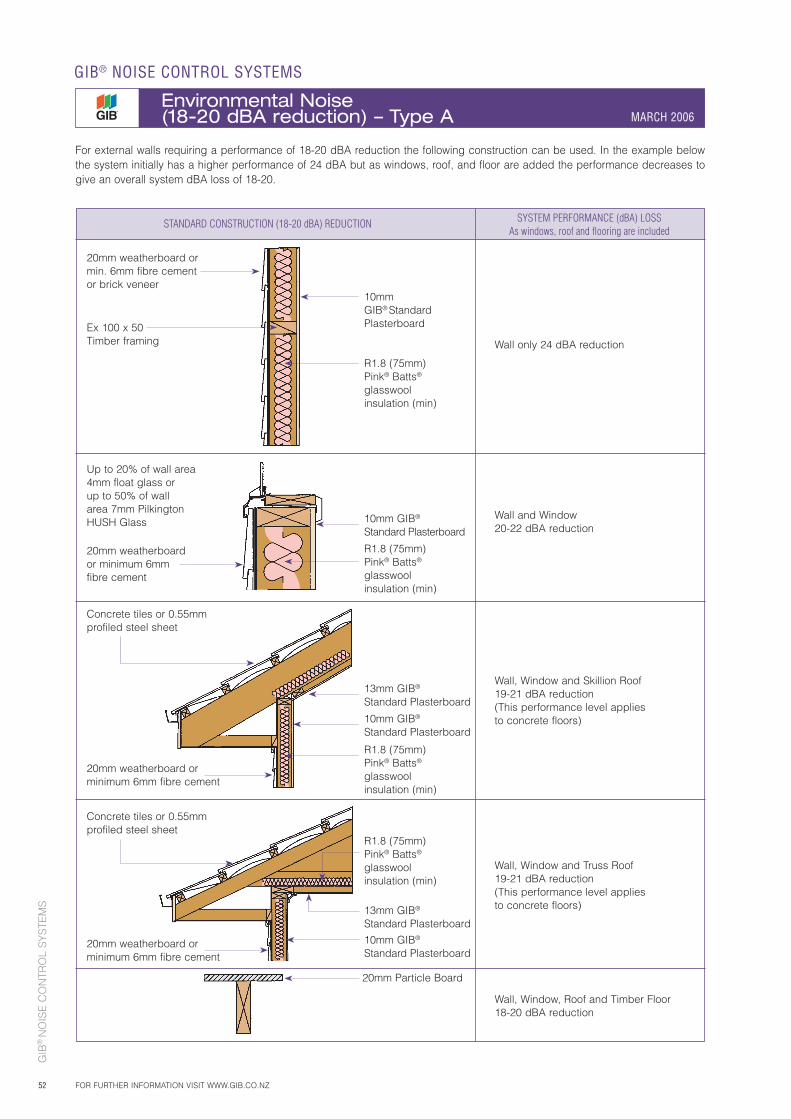
GIB
® N
OIS
E C
ON
TRO
L S
YS
TEM
S
52
GIB® NOISE CONTROL SYSTEMS
Environmental Noise (18-20 dBA reduction) – Type A MARCH 2006
FOR FURTHER INFORMATION VISIT WWW.GIB.CO.NZ
For external walls requiring a performance of 18-20 dBA reduction the following construction can be used. In the example below the system initially has a higher performance of 24 dBA but as windows, roof, and floor are added the performance decreases to give an overall system dBA loss of 18-20.
STANDARD CONSTRUCTION (18-20 dBA) REDUCTION SYSTEM PERFORMANCE (dBA) LOSS As windows, roof and flooring are included
20mm weatherboard or min. 6mm fibre cement or brick veneer
20mm weatherboard or minimum 6mm fibre cement
20mm weatherboard or minimum 6mm fibre cement
20mm weatherboard or minimum 6mm fibre cement
Ex 100 x 50 Timber framing
Up to 20% of wall area4mm float glass or up to 50% of wall area 7mm Pilkington HUSH Glass
10mm GIB® Standard Plasterboard
R1.8 (75mm) Pink® Batts® glasswool insulation (min)
10mm GIB®
Standard Plasterboard
R1.8 (75mm) Pink® Batts® glasswool insulation (min)
13mm GIB®
Standard Plasterboard
10mm GIB®
Standard Plasterboard
R1.8 (75mm) Pink® Batts® glasswool insulation (min)
R1.8 (75mm) Pink® Batts® glasswool insulation (min)
13mm GIB®
Standard Plasterboard
10mm GIB®
Standard Plasterboard
20mm Particle Board
Wall only 24 dBA reduction
Wall and Window20-22 dBA reduction
Wall, Window and Skillion Roof19-21 dBA reduction(This performance level applies to concrete floors)
Wall, Window, Roof and Timber Floor18-20 dBA reduction
Wall, Window and Truss Roof19-21 dBA reduction(This performance level applies to concrete floors)
Concrete tiles or 0.55mm profiled steel sheet
Concrete tiles or 0.55mm profiled steel sheet
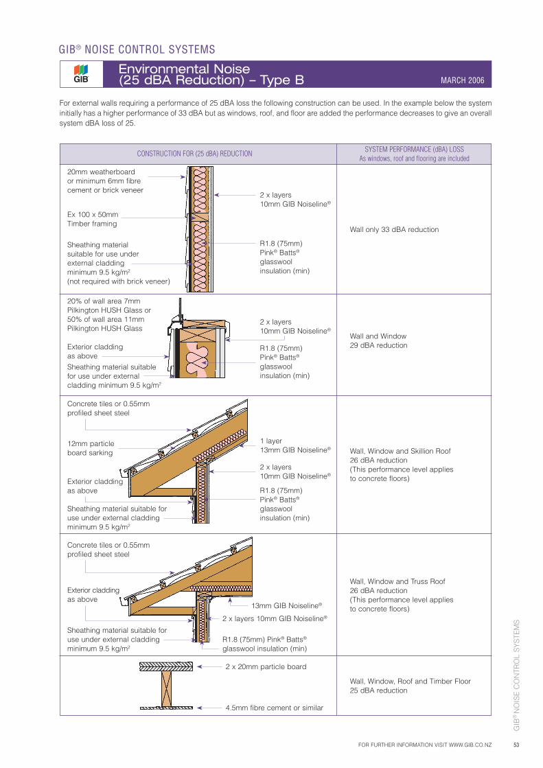
GIB
® N
OIS
E C
ON
TRO
L S
YS
TEM
S
53
For external walls requiring a performance of 25 dBA loss the following construction can be used. In the example below the system initially has a higher performance of 33 dBA but as windows, roof, and floor are added the performance decreases to give an overall system dBA loss of 25.
CONSTRUCTION FOR (25 dBA) REDUCTION SYSTEM PERFORMANCE (dBA) LOSS As windows, roof and flooring are included
20mm weatherboard or minimum 6mm fibre cement or brick veneer
12mm particle board sarking
Exterior cladding as above
Exterior cladding as above
Ex 100 x 50mm Timber framing
Sheathing material suitable for use under external cladding minimum 9.5 kg/m2 (not required with brick veneer)
Sheathing material suitable for use under external cladding minimum 9.5 kg/m2
Sheathing material suitable for use under external cladding minimum 9.5 kg/m2
Exterior cladding as above
Sheathing material suitable for use under external cladding minimum 9.5 kg/m2
20% of wall area 7mm Pilkington HUSH Glass or 50% of wall area 11mm Pilkington HUSH Glass
2 x layers 10mm GIB Noiseline®
2 x layers 10mm GIB Noiseline®
R1.8 (75mm) Pink® Batts® glasswool insulation (min)
2 x layers 10mm GIB Noiseline®
R1.8 (75mm) Pink® Batts® glasswool insulation (min)
1 layer 13mm GIB Noiseline®
R1.8 (75mm) Pink® Batts® glasswool insulation (min)
R1.8 (75mm) Pink® Batts®
glasswool insulation (min)
2 x layers 10mm GIB Noiseline®
13mm GIB Noiseline®
4.5mm fibre cement or similar
2 x 20mm particle board
Wall only 33 dBA reduction
Wall and Window29 dBA reduction
Wall, Window and Skillion Roof26 dBA reduction(This performance level applies to concrete floors)
Wall, Window, Roof and Timber Floor25 dBA reduction
Wall, Window and Truss Roof26 dBA reduction(This performance level applies to concrete floors)
Concrete tiles or 0.55mm profiled sheet steel
Concrete tiles or 0.55mm profiled sheet steel
FOR FURTHER INFORMATION VISIT WWW.GIB.CO.NZ
GIB® NOISE CONTROL SYSTEMS
Environmental Noise (25 dBA Reduction) – Type B MARCH 2006
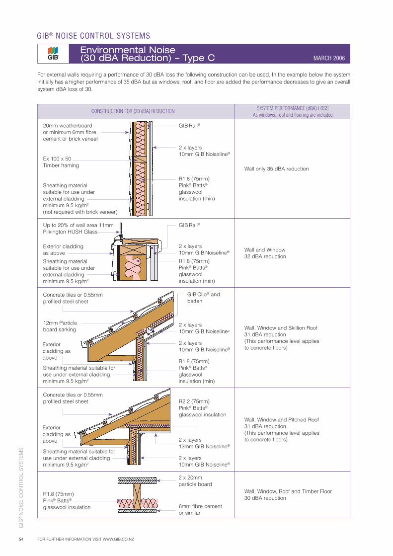
GIB
® N
OIS
E C
ON
TRO
L S
YS
TEM
S
54
For external walls requiring a performance of 30 dBA loss the following construction can be used. In the example below the system initially has a higher performance of 35 dBA but as windows, roof, and floor are added the performance decreases to give an overall system dBA loss of 30.
Sheathing material suitable for use under external cladding minimum 9.5 kg/m2
Ex 100 x 50 Timber framing
Sheathing material suitable for use under external cladding minimum 9.5 kg/m2
2 x layers 10mm GIB Noiseline®
2 x layers 10mm GIB Noiseline®
2 x layers 13mm GIB Noiseline®
2 x layers 10mm GIB Noiseline®
GIB Rail®
R1.8 (75mm) Pink® Batts® glasswool insulation (min)
GIB Rail®
R1.8 (75mm) Pink® Batts® glasswool insulation (min)
R2.2 (75mm) Pink® Batts® glasswool insulation
2 x 20mm particle board
Wall only 35 dBA reduction
Wall and Window32 dBA reduction
Wall, Window and Skillion Roof31 dBA reduction(This performance level applies to concrete floors)
Wall, Window, Roof and Timber Floor30 dBA reduction
Wall, Window and Pitched Roof31 dBA reduction(This performance level applies to concrete floors)
Concrete tiles or 0.55mm profiled steel sheet
12mm Particle board sarking
GIB Clip® and batten
R1.8 (75mm) Pink® Batts® glasswool insulation
GIB® NOISE CONTROL SYSTEMS
Environmental Noise (30 dBA Reduction) – Type C MARCH 2006
FOR FURTHER INFORMATION VISIT WWW.GIB.CO.NZ
CONSTRUCTION FOR (30 dBA) REDUCTION SYSTEM PERFORMANCE (dBA) LOSS As windows, roof and flooring are included
Concrete tiles or 0.55mm profiled steel sheet
Up to 20% of wall area 11mm Pilkington HUSH Glass
Sheathing material suitable for use under external cladding minimum 9.5 kg/m2 (not required with brick veneer)
20mm weatherboard or minimum 6mm fibre cement or brick veneer
2 x layers 10mm GIB Noiseline®
Exterior cladding as above
Sheathing material suitable for use under external cladding minimum 9.5 kg/m2
2 x layers 10mm GIB Noiseline®
R1.8 (75mm) Pink® Batts® glasswool insulation (min)
Exterior cladding as above
Exterior cladding as above
6mm fibre cementor similar
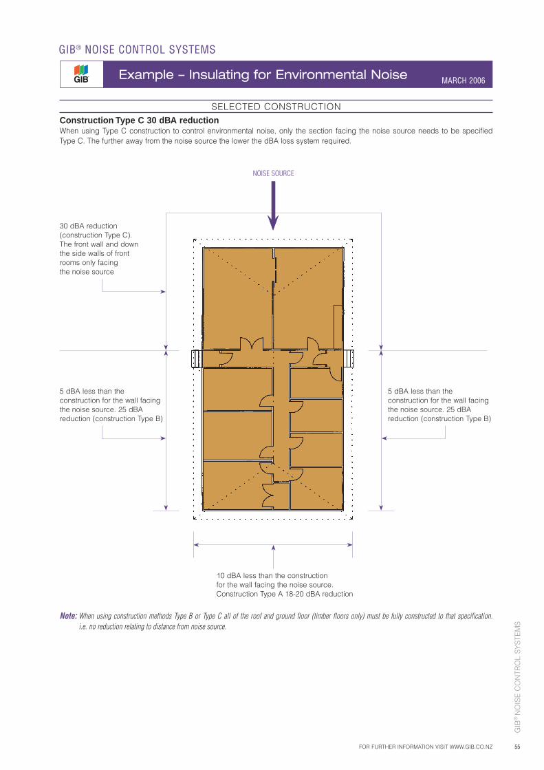
GIB
® N
OIS
E C
ON
TRO
L S
YS
TEM
S
55FOR FURTHER INFORMATION VISIT WWW.GIB.CO.NZ
GIB® NOISE CONTROL SYSTEMS
Example – Insulating for Environmental Noise MARCH 2006
SELECTED CONSTRUCTIONConstruction Type C 30 dBA reductionWhen using Type C construction to control environmental noise, only the section facing the noise source needs to be specified Type C. The further away from the noise source the lower the dBA loss system required.
NOISE SOURCE
5 dBA less than the construction for the wall facing the noise source. 25 dBA reduction (construction Type B)
5 dBA less than the construction for the wall facing the noise source. 25 dBA reduction (construction Type B)
10 dBA less than the construction for the wall facing the noise source. Construction Type A 18-20 dBA reduction
Note: When using construction methods Type B or Type C all of the roof and ground floor (timber floors only) must be fully constructed to that specification. i.e. no reduction relating to distance from noise source.
30 dBA reduction (construction Type C). The front wall and down the side walls of front rooms only facing the noise source
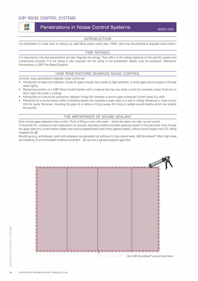
GIB
® N
OIS
E C
ON
TRO
L S
YS
TEM
S
56
INTRODUCTIONAny penetration in a wall, floor, or ceiling (e.g. light fitting, power outlet, pipe, HVAC, door) has the potential to degrade noise control.
FIRE RATINGSIt is important to note that penetrations can also degrade fire ratings. Their effect on fire ratings depends on the specific system and components involved. If a fire rating is also required, the fire rating of the penetration details must be assessed. Reference: Penetrations in GIB® Fire Rated Systems.
HOW PENETRATIONS DEGRADE NOISE CONTROLCommon ways penetrations degrade noise control are:• Introduction of leaks (for example, minute air gaps through door jambs or light switches, or small gaps around pipes or through
down lights)• Replacing a portion of a GIB® Noise Control System with a material that has less noise control (for example a door, flush box or
down light into a wall or ceiling)• Introduction of a structural connection between linings (for example a service pipe connected to both sides of a wall)• Placement of a sound source within a building system (for example a water pipe in a wall or ceiling introduces a noise source
into the cavity. Moreover, mounting the pipe on a frame or lining causes the lining to radiate sound directly which can amplify the sound).
THE IMPORTANCE OF SOUND SEALANTEven minute gaps degrade noise control. Think of filling a room with water – where the water can leak, so can sound.To illustrate this, compare a wall measured in an acoustic laboratory before and after applying sealant to the perimeter. Even though the gaps were tiny (under bottom plates and around plasterboard fixed firmly against plates), without sound sealant the STC rating dropped 20 dB! Mouldings (e.g. architraves), paint and wallpaper are generally not sufficient to stop sound leaks. GIB Soundseal® offers high mass and elasticity to accommodate building movement – do not use a general purpose gap filler.
GIB® NOISE CONTROL SYSTEMS
Penetrations in Noise Control Systems MARCH 2006
FOR FURTHER INFORMATION VISIT WWW.GIB.CO.NZ
Use GIB Soundseal® around perimeter
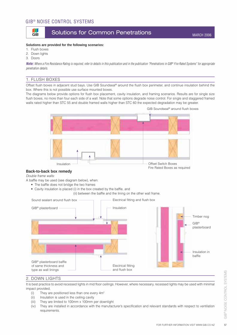
GIB
® N
OIS
E C
ON
TRO
L S
YS
TEM
S
57
Solutions are provided for the following scenarios:1. Flush boxes2. Down lights3. Doors
Note: Where a Fire Resistance Rating is required, refer to details in this publication and in the publication “Penetrations in GIB® Fire Rated Systems” for appropriate penetration details.
1. FLUSH BOXESOffset flush boxes in adjacent stud bays. Use GIB Soundseal® around the flush box perimeter, and continue insulation behind the box. Where this is not possible use surface mounted boxes.The diagrams below provide options for flush box placement, cavity insulation, and framing scenarios. Results are for single size flush boxes, no more than four each side of a wall. Note that some options degrade noise control. For single and staggered framed walls rated higher than STC 55 and double framed walls higher than STC 60 the expected degradation may be greater.
GIB Soundseal® around flush boxes
Offset Switch BoxesFire Rated Boxes as required
Insulation
Back-to-back box remedyDouble frame walls:A baffle may be used (see diagram below), when: • The baffle does not bridge the two frames • Cavity insulation is placed (i) in the box created by the baffle, and
(ii) between the baffle and the lining on the other wall frame.
GIB® plasterboard baffle of same thickness and type as wall linings
Electrical fitting and flush box
Sound sealant around flush box GIB® plasterboard
Electrical fitting and flush box
Insulation
Timber nog
GIB® plasterboard
Insulation inbaffle
FOR FURTHER INFORMATION VISIT WWW.GIB.CO.NZ
GIB® NOISE CONTROL SYSTEMS
Solutions for Common Penetrations MARCH 2006
2. DOWN LIGHTSIt is best practice to avoid recessed lights in mid floor ceilings. However, where necessary, recessed lights may be used with minimal impact provided, (i) They are positioned less than one every 4m2
(ii) Insulation is used in the ceiling cavity (iii) They are limited to 100mm x 100mm per downlight (iv) They are installed in accordance with the manufacturer’s specification and relevant standards with respect to ventilation
requirements.
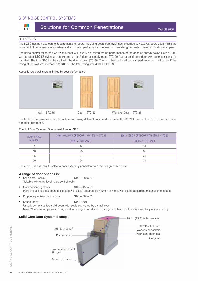
GIB
® N
OIS
E C
ON
TRO
L S
YS
TEM
S
58
GIB® NOISE CONTROL SYSTEMS
Solutions for Common Penetrations MARCH 2006
FOR FURTHER INFORMATION VISIT WWW.GIB.CO.NZ
3. DOORSThe NZBC has no noise control requirements for doors, including doors from dwellings to corridors. However, doors usually limit the noise control performance of a system and a minimum performance is required to meet design acoustic comfort and satisfy occupants.
The noise control rating of a wall with a door will usually be limited by the performance of the door, as shown below. Here a 10m2 wall is rated STC 55 (without a door) and a 1.8m2 door assembly rated STC 30 (e.g. a solid core door with perimeter seals) is installed. The total STC for the wall with the door is only STC 36. The door has reduced the wall performance significantly. If the rating of the wall was increased to STC 65, the total rating would still be STC 36.
Acoustic rated wall system limited by door performance
The table below provides examples of how combining different doors and walls affects STC. Wall size relative to door size can make a modest difference.
Effect of Door Type and Door + Wall Area on STC
DOOR + WALL AREA (m2)
36mm HOLLOW CORE DOOR – NO SEALS = STC 18 36mm SOLID CORE DOOR WITH SEALS = STC 30
DOOR + STC 55 WALL DOOR + STC 55 WALL
6 24 34
10 25 36
15 27 38
20 28 39
Therefore, it is essential to select a door assembly consistent with the design comfort level.
Wall = STC 55 Wall and Door = STC 36Door = STC 30
75mm (R1.8) bulk insulation
GIB® PlasterboardGIB Soundseal® Wedges or packers
Proprietary door seal
Bottom door seal
Planted stop
Solid core door leaf 19kg/m2
Door jamb
A range of door options is:• Solid core – seals STC ~ 28 to 32 Suitable with entry level noise control walls
• Communicating doors STC ~ 45 to 50 Pairs of back-to-back doors (solid core with seals) separated by 30mm or more, with sound absorbing material on one face
• Proprietary noise control doors STC ~ 36 to 50
• Sound lobby STC ~ 50+ Usually comprises two solid doors with seals separated by a small room.
Note: Where sound passes through a door, along a corridor, and through another door there is essentially a sound lobby.
Solid Core Door System Example
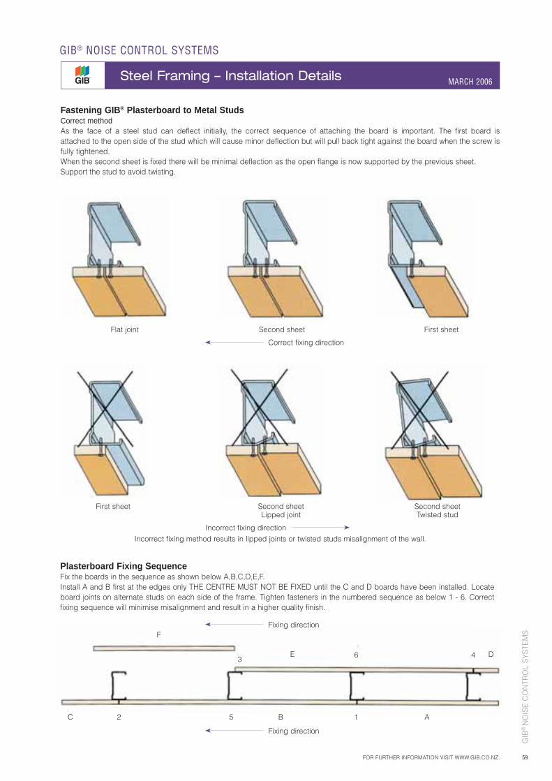
GIB
® N
OIS
E C
ON
TRO
L S
YS
TEM
S
59FOR FURTHER INFORMATION VISIT WWW.GIB.CO.NZ.
GIB® NOISE CONTROL SYSTEMS
Steel Framing – Installation Details MARCH 2006
Fastening GIB® Plasterboard to Metal StudsCorrect methodAs the face of a steel stud can deflect initially, the correct sequence of attaching the board is important. The first board is attached to the open side of the stud which will cause minor deflection but will pull back tight against the board when the screw is fully tightened.When the second sheet is fixed there will be minimal deflection as the open flange is now supported by the previous sheet.Support the stud to avoid twisting.
Flat joint Second sheet First sheet
Correct fixing direction
First sheet Second sheet Second sheet Lipped joint Twisted stud
Incorrect fixing direction
Incorrect fixing method results in lipped joints or twisted studs misalignment of the wall.
Plasterboard Fixing SequenceFix the boards in the sequence as shown below A,B,C,D,E,F.Install A and B first at the edges only THE CENTRE MUST NOT BE FIXED until the C and D boards have been installed. Locate board joints on alternate studs on each side of the frame. Tighten fasteners in the numbered sequence as below 1 - 6. Correct fixing sequence will minimise misalignment and result in a higher quality finish.
3 6 4
F
E
2C B5 1
Fixing direction
Fixing direction
D
A
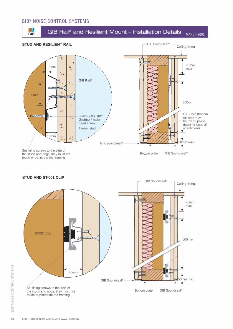
GIB
® N
OIS
E C
ON
TRO
L S
YS
TEM
S
60
600mm
75mm max
Ceiling lining
50mm maxGIB Soundseal®
Bottom plate
GIB Rail® (bottom rail only may be fixed upside down for ease of attachment)
GIB Rail®
32mm x 8g GIB® Grabber® wafer head screw
Set lining screws to the side of the studs and nogs, they must not touch or penetrate the framing
Timber stud
3mm
13mm
39mm
STUD AND RESILIENT RAIL
GIB Soundseal®
STUD AND ST-001 CLIP
GIB® NOISE CONTROL SYSTEMS
GIB Rail® and Resilient Mount – Installation Details MARCH 2006
FOR FURTHER INFORMATION VISIT WWW.GIB.CO.NZ
600mm
75mm max
Ceiling lining
50mm maxGIB Soundseal®
Bottom plate GIB Soundseal®
GIB Soundseal®
GIB Soundseal®
ST-001 Clip
40mm
Set lining screws to the side of the studs and nogs, they must not touch or penetrate the framing
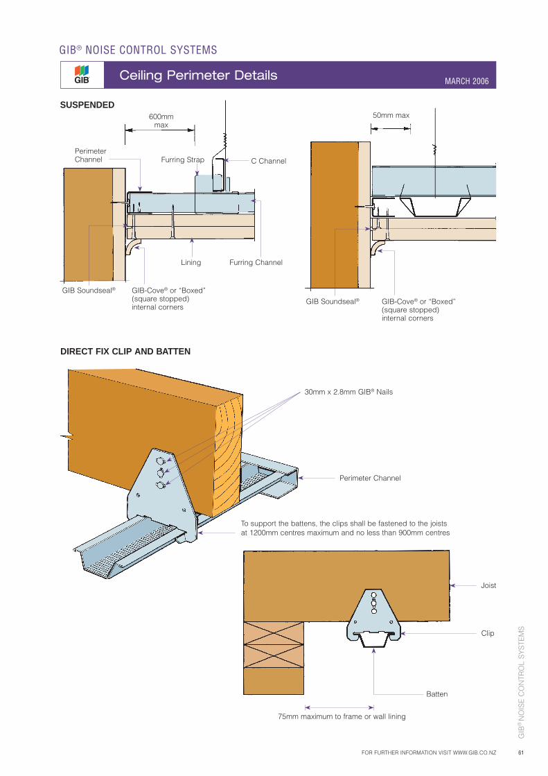
GIB
® N
OIS
E C
ON
TRO
L S
YS
TEM
S
61
GIB-Cove® or “Boxed” (square stopped) internal corners
GIB Soundseal®
Perimeter Channel Furring Strap
600mm max
C Channel
Lining Furring Channel
GIB-Cove® or “Boxed” (square stopped) internal corners
GIB Soundseal®
50mm max
FOR FURTHER INFORMATION VISIT WWW.GIB.CO.NZ
GIB® NOISE CONTROL SYSTEMS
Ceiling Perimeter Details MARCH 2006
SUSPENDED
DIRECT FIX CLIP AND BATTEN
30mm x 2.8mm GIB® Nails
Perimeter Channel
To support the battens, the clips shall be fastened to the joists at 1200mm centres maximum and no less than 900mm centres
Joist
Clip
Batten
75mm maximum to frame or wall lining
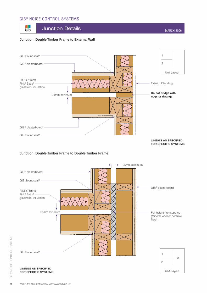
GIB
® N
OIS
E C
ON
TRO
L S
YS
TEM
S
62
GIB Soundseal®
LININGS AS SPECIFIED FOR SPECIFIC SYSTEMS
Do not bridge with nogs or dwangs
Exterior Cladding
GIB® plasterboard
GIB Soundseal®
GIB® plasterboard
R1.8 (75mm) Pink® Batts®
glasswool insulation
25mm minimum
GIB Soundseal®
LININGS AS SPECIFIED FOR SPECIFIC SYSTEMS
Full height fire stopping(Mineral wool or ceramic fibre)
GIB® plasterboard
GIB® plasterboard
GIB Soundseal®
25mm minimum
25mm minimum
Junction: Double Timber Frame to External Wall
Junction: Double Timber Frame to Double Timber Frame
1
2
Unit Layout
1
2
Unit Layout
3
R1.8 (75mm) Pink® Batts® glasswool insulation
GIB® NOISE CONTROL SYSTEMS
Junction Details MARCH 2006
FOR FURTHER INFORMATION VISIT WWW.GIB.CO.NZ
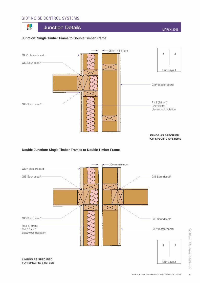
GIB
® N
OIS
E C
ON
TRO
L S
YS
TEM
S
63
Junction: Single Timber Frame to Double Timber Frame
Double Junction: Single Timber Frames to Double Timber Frame
25mm minimum
GIB Soundseal®
GIB Soundseal®
LININGS AS SPECIFIED FOR SPECIFIC SYSTEMS
GIB® plasterboard
GIB® plasterboard
GIB Soundseal® GIB Soundseal®
GIB Soundseal®GIB Soundseal®
LININGS AS SPECIFIED FOR SPECIFIC SYSTEMS
GIB® plasterboard
GIB® plasterboard
25mm minimum
1 2
Unit Layout
1 2
Unit Layout
R1.8 (75mm) Pink® Batts®
glasswool insulation
R1.8 (75mm) Pink® Batts® glasswool insulation
FOR FURTHER INFORMATION VISIT WWW.GIB.CO.NZ
GIB® NOISE CONTROL SYSTEMS
Junction Details MARCH 2006
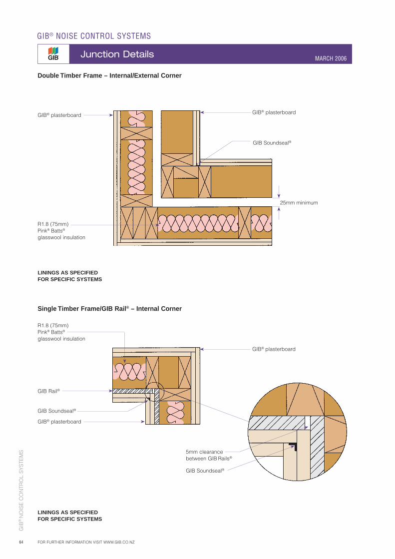
GIB
® N
OIS
E C
ON
TRO
L S
YS
TEM
S
64
LININGS AS SPECIFIED FOR SPECIFIC SYSTEMS
GIB® plasterboard GIB® plasterboard
25mm minimum
GIB Soundseal®
GIB Rail®
GIB Soundseal®
LININGS AS SPECIFIED FOR SPECIFIC SYSTEMS
5mm clearance between GIB Rails®
GIB® plasterboard
GIB® plasterboard
GIB Soundseal®
Double Timber Frame – Internal/External Corner
Single Timber Frame/GIB Rail® – Internal Corner
R1.8 (75mm) Pink® Batts®
glasswool insulation
R1.8 (75mm) Pink® Batts® glasswool insulation
GIB® NOISE CONTROL SYSTEMS
Junction Details MARCH 2006
FOR FURTHER INFORMATION VISIT WWW.GIB.CO.NZ
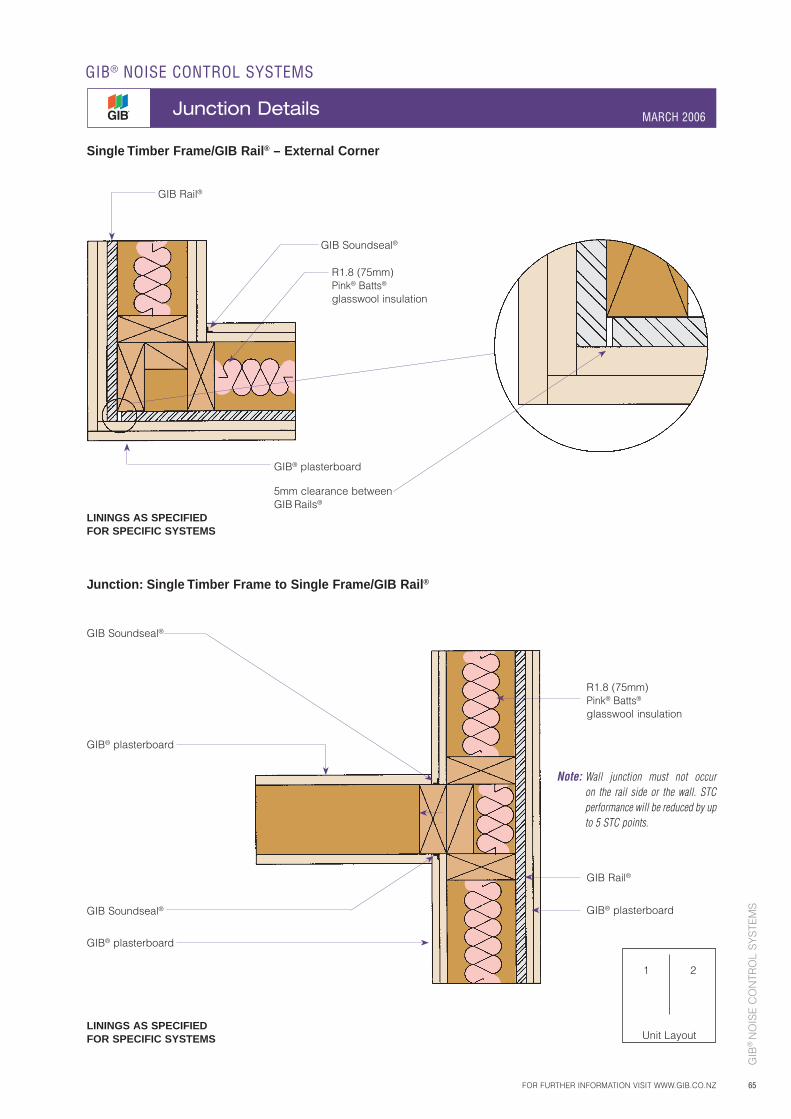
GIB
® N
OIS
E C
ON
TRO
L S
YS
TEM
S
65
Single Timber Frame/GIB Rail® – External Corner
Junction: Single Timber Frame to Single Frame/GIB Rail®
5mm clearance between GIB Rails®
GIB Rail®
GIB Rail®
GIB Soundseal®
LININGS AS SPECIFIED FOR SPECIFIC SYSTEMS
GIB® plasterboard
GIB Soundseal®
Note: Wall junction must not occur on the rail side or the wall. STC performance will be reduced by up to 5 STC points.
GIB® plasterboard
GIB Soundseal®
GIB® plasterboard
GIB® plasterboard
1 2
Unit Layout
R1.8 (75mm) Pink® Batts® glasswool insulation
R1.8 (75mm) Pink® Batts® glasswool insulation
LININGS AS SPECIFIED FOR SPECIFIC SYSTEMS
FOR FURTHER INFORMATION VISIT WWW.GIB.CO.NZ
GIB® NOISE CONTROL SYSTEMS
Junction Details MARCH 2006
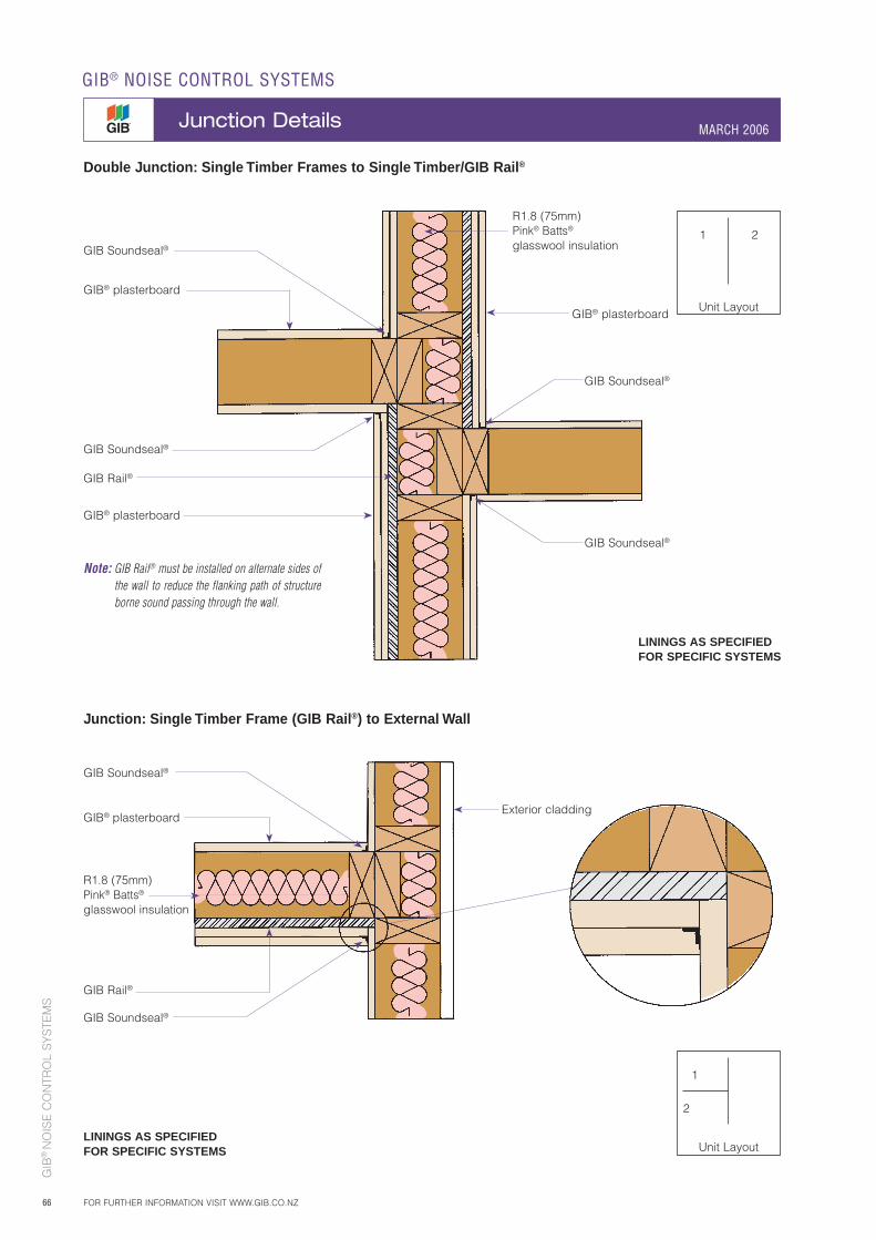
GIB
® N
OIS
E C
ON
TRO
L S
YS
TEM
S
66
LININGS AS SPECIFIED FOR SPECIFIC SYSTEMS
GIB® plasterboard
GIB® plasterboard
GIB® plasterboard
GIB Soundseal®
GIB Soundseal®
GIB Rail®
GIB Soundseal®
GIB Soundseal®
GIB Soundseal®
GIB Soundseal®
GIB Rail®
LININGS AS SPECIFIED FOR SPECIFIC SYSTEMS
Exterior claddingGIB® plasterboard
Note: GIB Rail® must be installed on alternate sides of the wall to reduce the flanking path of structure borne sound passing through the wall.
Double Junction: Single Timber Frames to Single Timber/GIB Rail®
Junction: Single Timber Frame (GIB Rail®) to External Wall
1 2
Unit Layout
1
2
Unit Layout
R1.8 (75mm) Pink® Batts® glasswool insulation
R1.8 (75mm) Pink® Batts® glasswool insulation
GIB® NOISE CONTROL SYSTEMS
Junction Details MARCH 2006
FOR FURTHER INFORMATION VISIT WWW.GIB.CO.NZ

GIB
® N
OIS
E C
ON
TRO
L S
YS
TEM
S
67
1
2
3
4
Unit Layout
GIB Clip®
GIB® Rondo® ceiling batten
GIB® Rondo® ceiling batten
GIB-Cove® or square stopped
GIB-Cove® or square stopped
GIB Soundseal®
GIB Soundseal®
GIB Soundseal®
GIB Soundseal®
Floor joists
Solid blocking
GIB Soundseal®
Floor joist offset to allow for the fastening of the flooring
LININGS AS SPECIFIED FOR SPECIFIC SYSTEMS
Carpet and underlay
GIB Soundseal®
GIB Clip®
Junction: Floor/Ceiling to Double Timber Framed Wall
• Floor/ceiling and wall are fire rated and sound rated• Joists at right angles to wall• Flooring non continuous over double frame
25mm minimum
25mm minimum
GIB Soundseal®1
2
3
4
Unit Layout
R1.8 (75mm) Pink® Batts® glasswool insulation
R1.8 (75mm) Pink® Batts® glasswool insulation
FOR FURTHER INFORMATION VISIT WWW.GIB.CO.NZ
GIB® NOISE CONTROL SYSTEMS
Junction Details MARCH 2006
Junction: As above but joists are parallel to wall over Double Frames
Fire stopping (Mineral wool or ceramic fibre)
Fire stopping (Mineral wool or ceramic fibre)
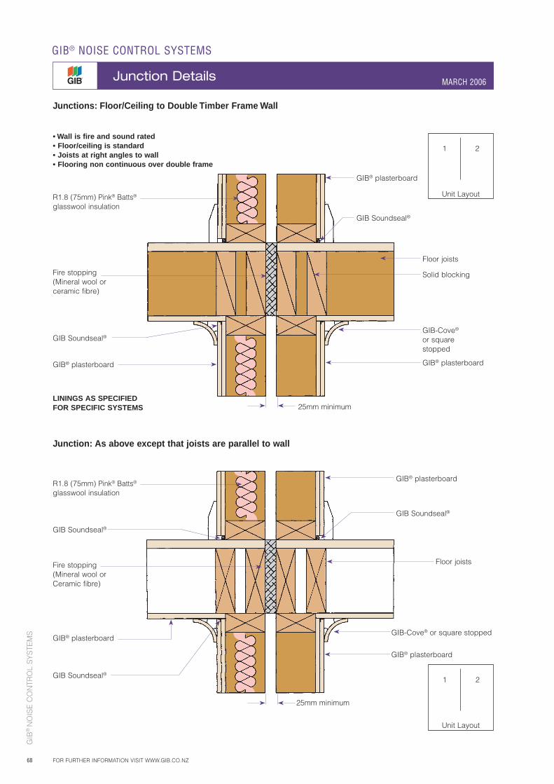
GIB
® N
OIS
E C
ON
TRO
L S
YS
TEM
S
68
1 2
Unit Layout
1 2
Unit Layout
Junction: As above except that joists are parallel to wall
GIB-Cove®
or square stopped
Fire stopping (Mineral wool or ceramic fibre)
Fire stopping (Mineral wool or Ceramic fibre)
GIB Soundseal®
GIB Soundseal®
Floor joists
Solid blocking
LININGS AS SPECIFIED FOR SPECIFIC SYSTEMS
GIB® plasterboard
GIB-Cove® or square stopped
Floor joists
GIB® plasterboard
GIB® plasterboard
GIB® plasterboard
GIB Soundseal®
GIB Soundseal®
GIB Soundseal®
• Wall is fire and sound rated• Floor/ceiling is standard• Joists at right angles to wall• Flooring non continuous over double frame
25mm minimum
25mm minimum
GIB® plasterboard
GIB® plasterboard
R1.8 (75mm) Pink® Batts® glasswool insulation
R1.8 (75mm) Pink® Batts® glasswool insulation
GIB® NOISE CONTROL SYSTEMS
Junction Details MARCH 2006
FOR FURTHER INFORMATION VISIT WWW.GIB.CO.NZ
Junctions: Floor/Ceiling to Double Timber Frame Wall
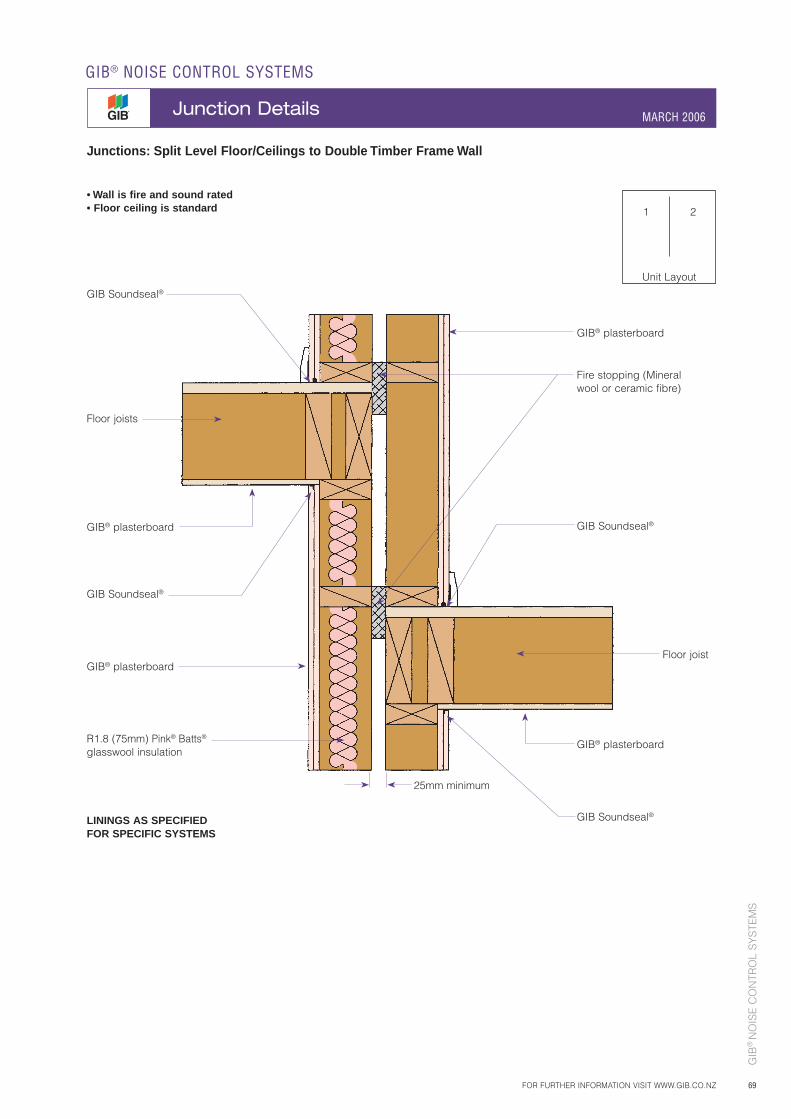
GIB
® N
OIS
E C
ON
TRO
L S
YS
TEM
S
69
Fire stopping (Mineral wool or ceramic fibre)
GIB Soundseal®
GIB Soundseal®
Floor joists
GIB Soundseal®
LININGS AS SPECIFIED FOR SPECIFIC SYSTEMS
GIB® plasterboard
GIB® plasterboard
Floor joist
GIB Soundseal®
GIB® plasterboard
GIB® plasterboard
Junctions: Split Level Floor/Ceilings to Double Timber Frame Wall
• Wall is fire and sound rated• Floor ceiling is standard
25mm minimum
1 2
Unit Layout
R1.8 (75mm) Pink® Batts® glasswool insulation
FOR FURTHER INFORMATION VISIT WWW.GIB.CO.NZ
GIB® NOISE CONTROL SYSTEMS
Junction Details MARCH 2006
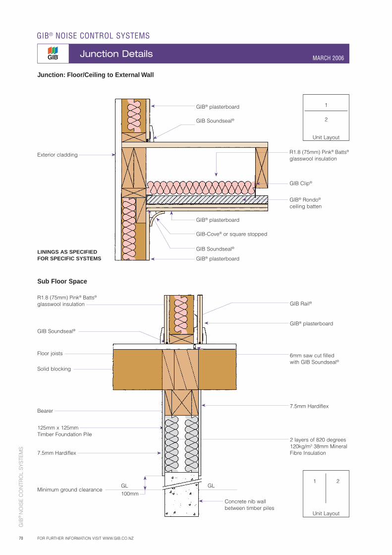
GIB
® N
OIS
E C
ON
TRO
L S
YS
TEM
S
70
Junction: Floor/Ceiling to External Wall
Sub Floor Space
GIB-Cove® or square stopped
Exterior cladding
GIB Soundseal®
GIB Soundseal®
LININGS AS SPECIFIED FOR SPECIFIC SYSTEMS
GIB® plasterboard
GIB® plasterboard
GIB® plasterboard
Floor joists
Solid blocking
Bearer
125mm x 125mmTimber Foundation Pile
6mm saw cut filled with GIB Soundseal®
7.5mm Hardiflex
7.5mm Hardiflex
Minimum ground clearanceGL
100mm
GL
GIB® plasterboard
GIB Rail®
2 layers of 820 degrees 120kg/m3 38mm Mineral Fibre Insulation
GIB Soundseal®
GIB Clip®
GIB® Rondo® ceiling batten
Concrete nib wall between timber piles
1 2
Unit Layout
1
2
Unit Layout
R1.8 (75mm) Pink® Batts® glasswool insulation
R1.8 (75mm) Pink® Batts® glasswool insulation
GIB® NOISE CONTROL SYSTEMS
Junction Details MARCH 2006
FOR FURTHER INFORMATION VISIT WWW.GIB.CO.NZ
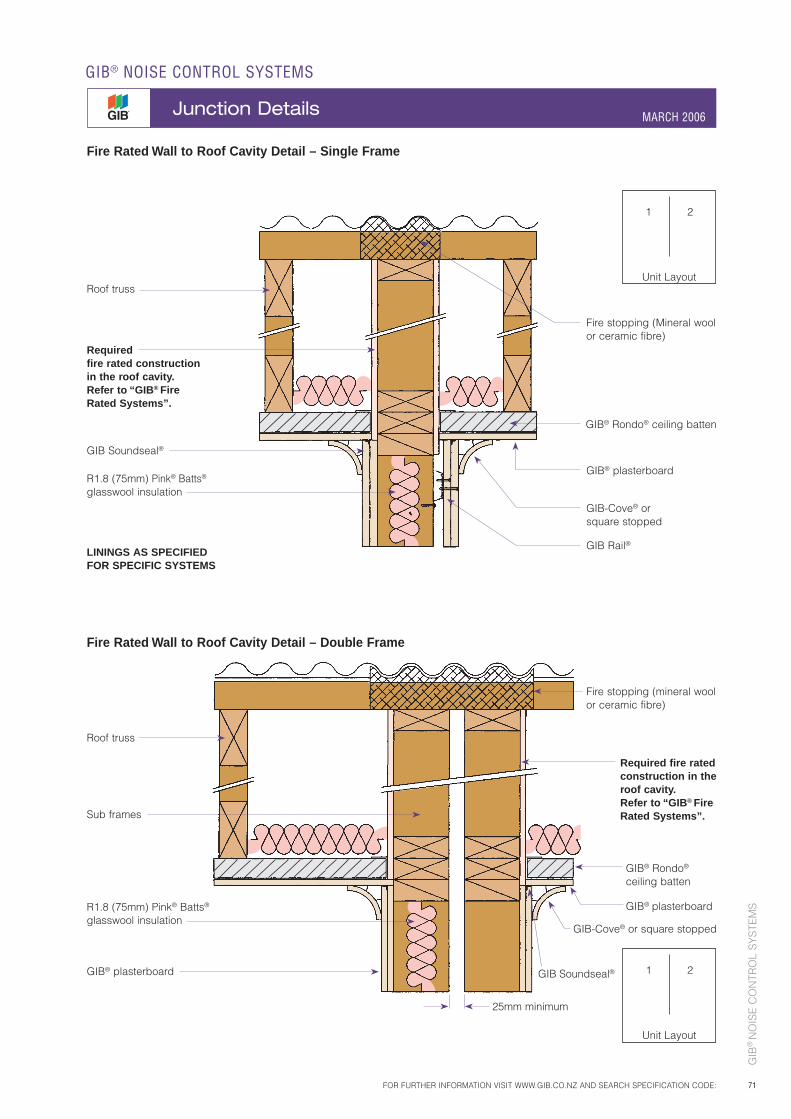
GIB
® N
OIS
E C
ON
TRO
L S
YS
TEM
S
71
GIB® Rondo® ceiling batten
GIB-Cove® or square stopped
Roof truss
GIB Rail®
Fire stopping (Mineral wool or ceramic fibre)
GIB Soundseal®
LININGS AS SPECIFIED FOR SPECIFIC SYSTEMS
Required fire rated construction in the roof cavity.Refer to “GIB® Fire Rated Systems”.
GIB® plasterboard
GIB® Rondo® ceiling batten
GIB-Cove® or square stopped
Fire stopping (mineral wool or ceramic fibre)
GIB® plasterboard
GIB® plasterboard GIB Soundseal®
Fire Rated Wall to Roof Cavity Detail – Single Frame
Fire Rated Wall to Roof Cavity Detail – Double Frame
25mm minimum
1 2
Unit Layout
1 2
Unit Layout
R1.8 (75mm) Pink® Batts®
glasswool insulation
R1.8 (75mm) Pink® Batts®
glasswool insulation
Roof truss
Sub frames
FOR FURTHER INFORMATION VISIT WWW.GIB.CO.NZ AND SEARCH SPECIFICATION CODE:
GIB® NOISE CONTROL SYSTEMS
Junction Details MARCH 2006
Required fire rated construction in the roof cavity.Refer to “GIB® Fire Rated Systems”.
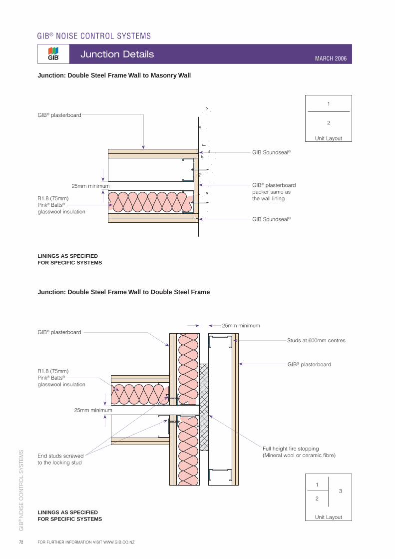
GIB
® N
OIS
E C
ON
TRO
L S
YS
TEM
S
72
Junction: Double Steel Frame Wall to Masonry Wall
Junction: Double Steel Frame Wall to Double Steel Frame
Full height fire stopping (Mineral wool or ceramic fibre)
GIB Soundseal®
GIB Soundseal®
GIB® plasterboard
GIB® plasterboard packer same as the wall lining
End studs screwed to the locking stud
GIB® plasterboard
GIB® plasterboard
25mm minimum
25mm minimum
25mm minimum
1
2
Unit Layout
1
2
Unit Layout
3
R1.8 (75mm) Pink® Batts®
glasswool insulation
R1.8 (75mm) Pink® Batts®
glasswool insulation
Studs at 600mm centres
LININGS AS SPECIFIED FOR SPECIFIC SYSTEMS
LININGS AS SPECIFIED FOR SPECIFIC SYSTEMS
GIB® NOISE CONTROL SYSTEMS
Junction Details MARCH 2006
FOR FURTHER INFORMATION VISIT WWW.GIB.CO.NZ
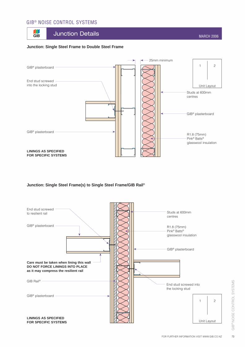
GIB
® N
OIS
E C
ON
TRO
L S
YS
TEM
S
73
1 2
Unit Layout
GIB® plasterboard
GIB® plasterboard
GIB® plasterboard
Studs at 600mm centres
End stud screwed into the locking stud
LININGS AS SPECIFIED FOR SPECIFIC SYSTEMS
Junction: Single Steel Frame to Double Steel Frame
25mm minimum
R1.8 (75mm) Pink® Batts® glasswool insulation
Junction: Single Steel Frame(s) to Single Steel Frame/GIB Rail®
1 2
Unit Layout
End stud screwed to resilient rail
Care must be taken when lining this wallDO NOT FORCE LININGS INTO PLACEas it may compress the resilient rail
LININGS AS SPECIFIED FOR SPECIFIC SYSTEMS
GIB® plasterboard
GIB® plasterboard
End stud screwed into the locking stud
GIB® plasterboard
GIB Rail®
R1.8 (75mm) Pink® Batts® glasswool insulation
Studs at 600mm centres
FOR FURTHER INFORMATION VISIT WWW.GIB.CO.NZ
GIB® NOISE CONTROL SYSTEMS
Junction Details MARCH 2006
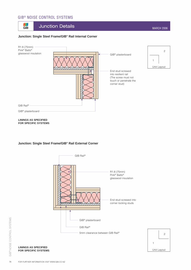
GIB
® N
OIS
E C
ON
TRO
L S
YS
TEM
S
74
Junction: Single Steel Frame/GIB® Rail External Corner
GIB Rail®
LININGS AS SPECIFIED FOR SPECIFIC SYSTEMS
GIB® plasterboard
GIB® plasterboard
End stud screwed into resilient rail(The screw must not touch or penetrate the corner stud)
GIB Rail®
LININGS AS SPECIFIED FOR SPECIFIC SYSTEMS
GIB® plasterboard
R1.8 (75mm)Pink® Batts® glasswool insulation
R1.8 (75mm) Pink® Batts® glasswool insulation
GIB Rail®
5mm clearance between GIB Rail®
End stud screwed into corner locking studs
1
2
Unit Layout
GIB® NOISE CONTROL SYSTEMS
Junction Details MARCH 2006
FOR FURTHER INFORMATION VISIT WWW.GIB.CO.NZ
Junction: Single Steel Frame/GIB® Rail Internal Corner
1
2
Unit Layout
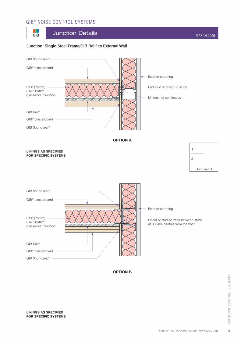
GIB
® N
OIS
E C
ON
TRO
L S
YS
TEM
S
75FOR FURTHER INFORMATION VISIT WWW.GIB.CO.NZ
GIB® NOISE CONTROL SYSTEMS
Junction Details MARCH 2006
Junction: Single Steel Frame/GIB Rail® to External Wall
OPTION A
LININGS AS SPECIFIED FOR SPECIFIC SYSTEMS
LININGS AS SPECIFIED FOR SPECIFIC SYSTEMS
OPTION B
1
2
Unit Layout
GIB Rail®
GIB® plasterboard
GIB Soundseal®
Exterior cladding
Offcut of stud or track between studs at 800mm centres from the floor
GIB Soundseal®
R1.8 (75mm) Pink® Batts® glasswool insulation
GIB® plasterboard
GIB Rail®
GIB® plasterboard
GIB Soundseal®
Exterior cladding
End stud screwed to studs
Linings not continuous
GIB Soundseal®
R1.8 (75mm) Pink® Batts®
glasswool insulation
GIB® plasterboard

GIB
® N
OIS
E C
ON
TRO
L S
YS
TEM
S
76
GIB® plasterboard
R1.8 (75mm) Pink® Batts® glasswool insulation
GIB Soundseal®GIB® Rondo® Quiet Stud®
R1.8 (75mm) Pink® Batts® glasswool insulation
GIB®
plasterboard
R1.8 (75mm) Pink® Batts® glasswool insulation
GIB Soundseal®
GIB Soundseal®
GIB® Rondo®
Quiet Stud®
GIB® Rondo® Quiet Stud® – T-intersection detail
GIB® Rondo® Quiet Stud® – Corner detail
GIB® Rondo® Quiet Stud® – Top track detail
GIB® Rondo® Quiet Stud® – Bottom track detail
R1.8 (75mm) Pink® Batts® glasswool insulation
R1.8 (75mm) Pink® Batts® glasswool insulation
R1.8 (75mm) Pink® Batts® glasswool insulation
GIB® plasterboard
Top track
GIB Soundseal®
GIB® Rondo®
Quiet Stud®
15mmexpansion gap
R1.8 (75mm) Pink® Batts® glasswool insulation
GIB® plasterboard
Bottom track
GIB Soundseal®
GIB® Rondo®
Quiet Stud®
1 2
Unit Layout
3
LININGS AS SPECIFIED FOR SPECIFIC SYSTEMS
LININGS AS SPECIFIED FOR SPECIFIC SYSTEMS
GIB® NOISE CONTROL SYSTEMS
Junction Details MARCH 2006
FOR FURTHER INFORMATION VISIT WWW.GIB.CO.NZ
Gap to outer lining
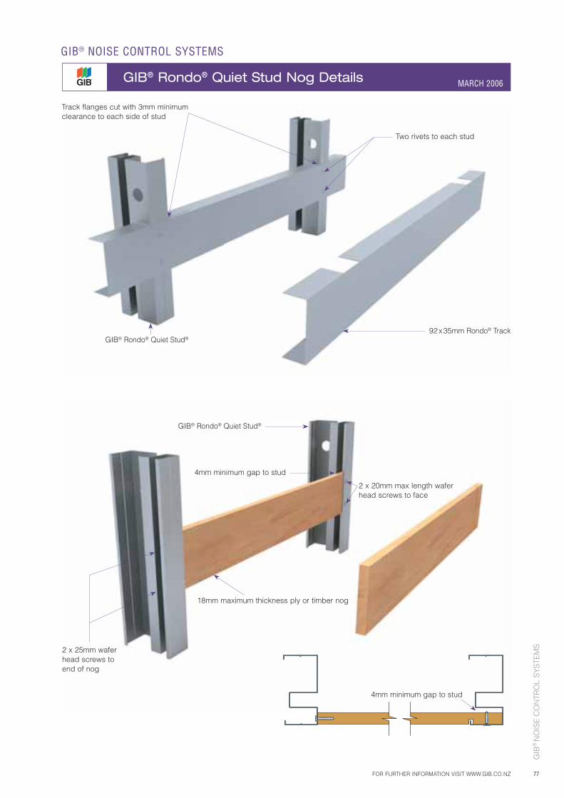
GIB
® N
OIS
E C
ON
TRO
L S
YS
TEM
S
77
Track flanges cut with 3mm minimum clearance to each side of stud
GIB® Rondo® Quiet Stud®92 x 35mm Rondo® Track
Two rivets to each stud
18mm maximum thickness ply or timber nog
GIB® Rondo® Quiet Stud®
4mm minimum gap to stud
2 x 20mm max length wafer head screws to face
2 x 25mm wafer head screws to end of nog
FOR FURTHER INFORMATION VISIT WWW.GIB.CO.NZ
GIB® NOISE CONTROL SYSTEMS
GIB® Rondo® Quiet Stud Nog Details MARCH 2006
4mm minimum gap to stud
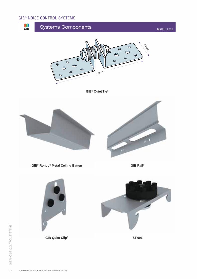
GIB
® N
OIS
E C
ON
TRO
L S
YS
TEM
S
78
GIB® Quiet Tie®
40mm
150mm
GIB® Rondo® Metal Ceiling Batten GIB Rail®
GIB Quiet Clip® ST-001
GIB® NOISE CONTROL SYSTEMS
Systems Components MARCH 2006
FOR FURTHER INFORMATION VISIT WWW.GIB.CO.NZ
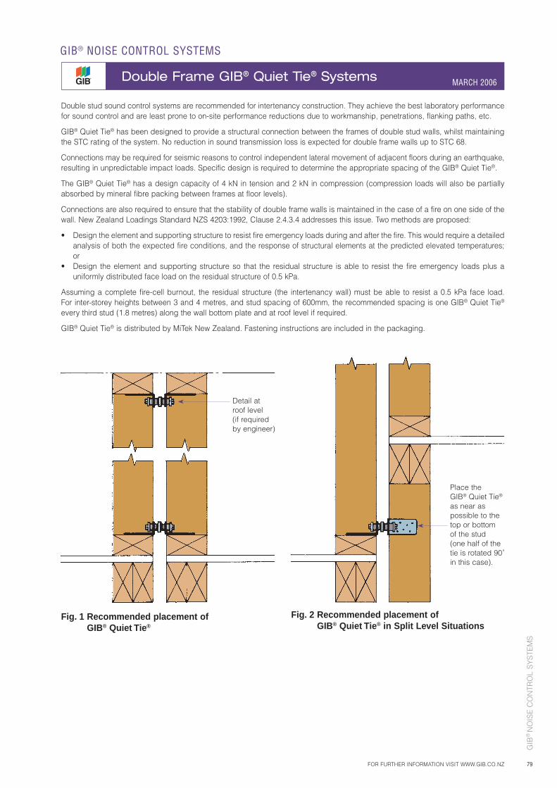
GIB
® N
OIS
E C
ON
TRO
L S
YS
TEM
S
79
Double stud sound control systems are recommended for intertenancy construction. They achieve the best laboratory performance for sound control and are least prone to on-site performance reductions due to workmanship, penetrations, flanking paths, etc.
GIB® Quiet Tie® has been designed to provide a structural connection between the frames of double stud walls, whilst maintaining the STC rating of the system. No reduction in sound transmission loss is expected for double frame walls up to STC 68.
Connections may be required for seismic reasons to control independent lateral movement of adjacent floors during an earthquake, resulting in unpredictable impact loads. Specific design is required to determine the appropriate spacing of the GIB® Quiet Tie®.
The GIB® Quiet Tie® has a design capacity of 4 kN in tension and 2 kN in compression (compression loads will also be partially absorbed by mineral fibre packing between frames at floor levels).
Connections are also required to ensure that the stability of double frame walls is maintained in the case of a fire on one side of the wall. New Zealand Loadings Standard NZS 4203:1992, Clause 2.4.3.4 addresses this issue. Two methods are proposed:
• Design the element and supporting structure to resist fire emergency loads during and after the fire. This would require a detailed analysis of both the expected fire conditions, and the response of structural elements at the predicted elevated temperatures; or
• Design the element and supporting structure so that the residual structure is able to resist the fire emergency loads plus a uniformly distributed face load on the residual structure of 0.5 kPa.
Assuming a complete fire-cell burnout, the residual structure (the intertenancy wall) must be able to resist a 0.5 kPa face load. For inter-storey heights between 3 and 4 metres, and stud spacing of 600mm, the recommended spacing is one GIB® Quiet Tie® every third stud (1.8 metres) along the wall bottom plate and at roof level if required.
GIB® Quiet Tie® is distributed by MiTek New Zealand. Fastening instructions are included in the packaging.
Detail at roof level (if required by engineer)
Place the GIB® Quiet Tie® as near as possible to the top or bottom of the stud(one half of the tie is rotated 90˚ in this case).
Fig. 1 Recommended placement of GIB® Quiet Tie®
Fig. 2 Recommended placement of GIB® Quiet Tie® in Split Level Situations
FOR FURTHER INFORMATION VISIT WWW.GIB.CO.NZ
GIB® NOISE CONTROL SYSTEMS
Double Frame GIB® Quiet Tie® Systems MARCH 2006
GIB
® N
OIS
E C
ON
TRO
L S
YS
TEM
S
80
AbsorptionThe conversion of sound energy into heat. Absorption coefficient is the fraction of incident sound energy not reflected.
AcousticConcerned with the sense of hearing and includes both reverberant and transmitted sound energy.
Airborne SoundSound energy transmitted through the air.
ASTMAmerican Society for Testing and Materials.
dBAn abbreviation for decibel. A logarithmic ratio to a reference level. A decibel is a tenth of a Bel.
dB(A)‘A’ weighted decibel. The (A) refers to a filter applied to make a measurement more sensitive to sounds the human hearing system is sensitive to at moderate sound levels.
FIICField Impact Insulation Class: In essence, an IIC measurement undertaken on a building site.
FlankingSound transmission to a receiving room by a path other than the building element of interest.
FSTCField Sound Transmission Class: In essence, a STC measurement undertaken on a building site.
IICImpact Insulation Class: A rating for the impact sound insulation capability of a floor/ceiling system in a laboratory. The measurement range is 100 to 3150Hz. Generally, the higher the rating the better the performance.
Impact SoundSound energy by striking a surface (e.g. footsteps, dropping an object).
ISOAbbreviation for “International Standards Organisation”.
L10The noise level, which is equal to or exceeded for 10% of the measurement period.
LeqThe measurement of the average sound level over a set period of time.
Ldn24 hour average sound pressure level. Sounds that occur between 10pm and 7am are given more weighting.
NoiseSound that is unwanted by the listener.
NRCNoise Reduction Coefficient: The average of a materials absorption coefficient at 250, 500, 100 and 2000Hz.
PNCPreferred Noise Criteria. The ambient sound level of a space, based on contours related to human response to noise.
ReverberationMultiple sound reflections so close in time that the human ear cannot distinguish them as separate sounds.
RwWeighted Sound Reduction Index: A rating of airborne sound reduction through a building element in a laboratory. Rw is an ISO rating and is derived from transmission loss measurements between 100 to 3150Hz. Generally, the higher the rating the better the performance.
SoundA travelling vibration through an elastic medium that may be detected by a hearing system.
STCSound Transmission Class: A rating of airborne sound reduction through a building element in a laboratory. STC is an ASTM rating and is derived from transmission loss measurements between 125 to 4000Hz. Generally, the higher the rating the better the performance.
Structure-borne SoundSound energy transmitted through a solid (e.g. along joists or service pipes).
Transmission LossThe difference in sound pressure levels between incident and transmitting sound.
GIB® NOISE CONTROL SYSTEMS
Technical Terminology MARCH 2006
FOR FURTHER INFORMATION VISIT WWW.GIB.CO.NZ
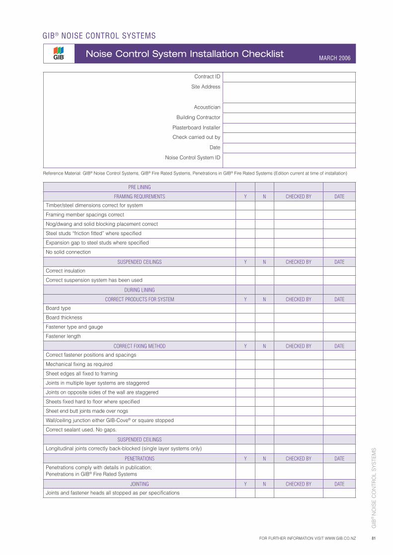
GIB
® N
OIS
E C
ON
TRO
L S
YS
TEM
S
81FOR FURTHER INFORMATION VISIT WWW.GIB.CO.NZ
GIB® NOISE CONTROL SYSTEMS
Noise Control System Installation Checklist MARCH 2006
Contract ID
Site Address
Acoustician
Building Contractor
Plasterboard Installer
Check carried out by
Date
Noise Control System ID
Reference Material: GIB® Noise Control Systems, GIB® Fire Rated Systems, Penetrations in GIB® Fire Rated Systems (Edition current at time of installation)
PRE LINING
FRAMING REQUIREMENTS Y N CHECKED BY DATE
Timber/steel dimensions correct for system
Framing member spacings correct
Nog/dwang and solid blocking placement correct
Steel studs “friction fitted” where specified
Expansion gap to steel studs where specified
No solid connection
SUSPENDED CEILINGS Y N CHECKED BY DATE
Correct insulation
Correct suspension system has been used
DURING LINING
CORRECT PRODUCTS FOR SYSTEM Y N CHECKED BY DATE
Board type
Board thickness
Fastener type and gauge
Fastener length
CORRECT FIXING METHOD Y N CHECKED BY DATE
Correct fastener positions and spacings
Mechanical fixing as required
Sheet edges all fixed to framing
Joints in multiple layer systems are staggered
Joints on opposite sides of the wall are staggered
Sheets fixed hard to floor where specified
Sheet end butt joints made over nogs
Wall/ceiling junction either GIB-Cove® or square stopped
Correct sealant used. No gaps.
SUSPENDED CEILINGS
Longitudinal joints correctly back-blocked (single layer systems only)
PENETRATIONS Y N CHECKED BY DATE
Penetrations comply with details in publication;Penetrations in GIB® Fire Rated Systems
JOINTING Y N CHECKED BY DATE
Joints and fastener heads all stopped as per specifications

GIB® NOISE CONTROL SYSTEMS
MARCH 2006
GIB
® N
OIS
E C
ON
TRO
L S
YS
TEM
S
82 FOR FURTHER INFORMATION VISIT WWW.GIB.CO.NZ AND SEARCH SPECIFICATION CODE:
Sustainability and the Environment
Environmental Choice
Waste Management
Winstone Wallboards is committed to protecting the environment. Environmental matters are integrated into all business activities:
• All operations of Winstone Wallboards will strive to meet all environmental regulatory requirements at all times.
• Protection of the environment is a day to day responsibility that we all must accept.
• We will treat the environment equally with all other operations and allocate appropriate management time and resources to address and continuously improve our activities.
• We will achieve our standards of performance through positive action, employee involvement and constant communication with our neighbours, local authorities and customers.
Winstone Wallboards is the first manufacturer of plasterboard to have products certified as environmentally preferable through Environmental Choice New Zealand. The Environmental Choice label acknowledges the product as meeting or exceeding the voluntary environmental declaration standard set by the NZ Eco-labelling Trust. The standard is a comprehensive life-cycle assessment which is scientifically and internationally recognised.
The Environmental Choice Label covers all GIB® plasterboard 13mm and greater in thickness.
Specify GIB® plasterboard with the Environmental Choice label as this ensures that the product selected minimises the impact on the environment. Consideration should be given to minimising on-site waste when designing and/or installing GIB® Plasterboard systems. For larger projects consideration should be given to the utilisation of Winstone Wallboards cut-to-length service to reduce the volume of waste produced.
GIB® plasterboard off cuts, if separated from other waste building materials, can be readily recycled. For larger projects the waste can be diverted to compost manufacturers who grind up the GIB® plasterboard and utilise it in compost. For smaller projects, the GIB® plasterboard can be ground up and spread around the building site.
GIB
® N
OIS
E C
ON
TRO
L S
YS
TEM
S
83FOR FURTHER INFORMATION VISIT WWW.GIB.CO.NZ AND SEARCH SPECIFICATION CODE:
GIB® NOISE CONTROL SYSTEMS
MARCH 2006Notes


GIB® Noise Control Systems, March 2006Winstone Wallboards Ltd accepts no liability if the GIB® Noise Control System is not designed and installed in strict accordance with instructions contained in this publication.
Use only the current specificationThis publication may be superseded by a new publication. Winstone Wallboards accepts no liability for reliance upon publications that have been superseded. You should check the current index of publications contained in your GIB® Technical Manual before using this publication. If you are unsure whether this is the current publication, simply call the GIB® Helpline on 0800 100 442.
SubstitutionGIB® Noise Control Systems are not generic. Where specified, GIB® branded components must be used when specifying and installing GIB® Noise Control Systems. Substitution is not in accordance with the instructions contained in this publication.
TrademarksThe names GIB®, GIB Fyreline®, GIB Ultraline®, GIB Braceline®, GIB Toughline®, GIB Noiseline®, GIB Aqualine®, GIB Tradeset®, GIB Plus 4®, GIB-Cove®, GIB Lite Blue®, GIBFix®, Quiet Stud®, GIB Rail®, GIB Sound Barrier®, GIB Soundseal®, GIB Clip®, the colour mauve for GIB Toughline®, the colour blue for GIB Braceline®, the colour pink for GIB Fyreline®, the colour green for GIB Aqualine®, and the ear device are registered trademarks of Fletcher Building Holdings Limited.
GIB® Help Line – Call Free
0800 100 442Free Facsimile
0800 229 222E-mail
[email protected] Website
http://www.gib.co.nzAucklandP O Box 12 256 Penrose. Telephone 0-9-633 0100. Facsimile 0-9-633 0101.
Copyright © Winstone Wallboards Ltd, 2006
Printed in New Zealand using mineral-oil-free inks on environmentally responsible Media Satin using PEFC pulp from a mill that is EMAS
accredited and ISO 14001 certified.

Winstone Wallboards Limited37 Felix Street, P O Box 12256
Penrose, Auckland, New Zealand
Phone 64-9-633 0100, Facsimile 64-9-633 0101
Internet website: http://www.gib.co.nz
E-mail: [email protected]
GIB® Helpline: 0800 100 442
Facsimile: 0800 229 222