gilair-3 & gilair-5 air sampling systems · 3 gilian® gilair-3 & gilair-5 air sampling...
TRANSCRIPT
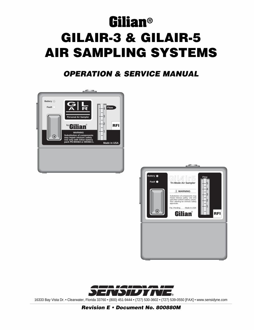
16333 Bay Vista Dr. • Clearwater, Florida 33760 • (800) 451-9444 • (727) 530-3602 • (727) 539-0550 [FAX] • www.sensidyne.com
Revision E • Document No. 800880M
Gilian®
GILAIR-3 & GILAIR-5AIR SAMPLING SYSTEMS
OPERATION & SERVICE MANUAL
Battery
Fault
Gilian®by
Substitution of componentsmay impair intrinsic safety.Use only with Gilian batterypack PN 800464 or 800464-1.
WARNING
Made in USA
4
3
2
1
Flow
Personal Air Sampler
GA
LR
RFI
AWARNING
Gilian®
Pat. Pending Made In USA
Substitution of components mayimpair intrinsic safety. Use onlyspecified GilAir5 battery packs.See Labeling for intrinsic safetyapprovals.
Tri-Mode Air SamplerAGil ir5
Battery
Fault 5
4
3
2
1
FlowA
RFI


3
Gilian® GILAIR-3 & GILAIR-5 AIR SAMPLING SYSTEMS
Sensidyne Document No. 800880M (Rev E)
The items listed below are shipped the Gilian GilAir-3/GilAir-5 Air Sampling System:
• GilAir-3 or GilAir-5 Air Sampling Pump
• Tool Kit
• Tubing
• Air Boss
• Restrictor
• Operation and Service Manual
• Registration Card/Warranty Card
PACKING LIST
ALWAYS check to make certainyou have received all of the items listed above.
If you have any questions or need assistance,contact your Gilian Sales Representative, or call
(800) 451-9444OR
(727) 530-3602
— PRELIMINARY —
Gilian® GILAIR-3 & GILAIR-5 AIR SAMPLING SYSTEMS
4 Sensidyne Document No. 800880M (Rev E)
DISCLAIMER
THE SELLER ASSUMES NO RESPONSIBILITY WHATSOEVER, TO ANY PARTY WHOSOEVER, FOR ANY
PROPERTY DAMAGE, PERSONAL INJURY, OR DEATH RECEIVED BY OR RESULTING FROM, IN
WHOLE, OR IN PART, THE IMPROPER USE, INSTALLATION, OR STORAGE OF THIS PRODUCT BY THE
USER, PERSON, FIRM, ENTITY, CORPORATION OR PARTY NOT ADHERING TO THE INSTRUCTIONS
AND WARNINGS IN THIS MANUAL, OR OTHERWISE PROVIDED BY THE SELLER OR FROM NOT AD-
HERING TO ALL FEDERAL, STATE, AND LOCAL ENVIRONMENTAL AND OCCUPATIONAL HEALTH AND
SAFETY LAWS AND REGULATIONS.
THE SELLER SHALL NOT BE LIABLE FOR DIRECT, INDIRECT, CONSEQUENTIAL, INCIDENTAL OR
OTHER DAMAGES RESULTING FROM THE SALE AND USE OF ANY GOODS AND SELLERS’ LIABILITY
HEREUNDER SHALL BE LIMITED TO REPAIR OR REPLACEMENT OF ANY GOODS FOUND DEFECTIVE.
THIS WARRANTY IS IN LIEU OF ALL OTHER WARRANTIES, EXPRESSED OR IMPLIED, INCLUDING BUT
NOT LIMITED TO THE IMPLIED WARRANTIES OF MERCHANTABILITY AND FITNESS FOR USE OR FOR
A PARTICULAR PURPOSE WHICH ARE EXPRESSLY DISCLAIMED.
PROPRIETARY NOTICE
This manual was prepared exclusively for the owner of the Sensidyne GilAir Air Sampling System. The material within this
manual is proprietary information and is to be used only to understand, operate, and service the instrument. By receiving
this document, the recipient agrees that neither this document nor the information disclosed within nor any part thereof
shall be reproduced or transferred, physically, electronically or in any other form, or used or disclosed to others for manu-
facturing or for any other purpose except as specifically authorized in writing by Sensidyne, Inc.
COPYRIGHT NOTICE
© 2001 Sensidyne, Inc. All Rights Reserved. No part of this document may be reproduced, transmitted, transcribed, stored
in a retrieval system, or translated into any language in any form by any means without the prior written permission of
Sensidyne, Inc..
TRADEMARK NOTICE
Sensidyne, the Sensidyne logo, Gilian, and the Gilian logo are registered trademarks. These trademarks are protected through
use and registration in the United States. The trademarks and servicemarks used in this document are the property of their
respective companies and are used only for informational and explanatory purposes.
5
Gilian® GILAIR-3 & GILAIR-5 AIR SAMPLING SYSTEMS
Sensidyne Document No. 800880M (Rev E)
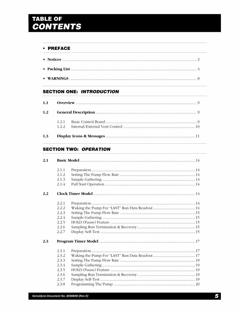
TABLE OFCONTENTS
• PREFACE
• Notices ...................................................................................................................................3
• Packing List .......................................................................................................................... 4
• WARNINGS ........................................................................................................................... 8
SECTION ONE: INTRODUCTION
1.1 Overview ..................................................................................................................... 9
1.2 General Description .................................................................................................. 9
1.2.1 Basic Control Board .........................................................................................91.2.2 Internal/External Vent Control ......................................................................10
1.3 Display Icons & Messages .......................................................................................11
SECTION TWO: OPERATION
2.1 Basic Model ................................................................................................................14
2.1.1 Preparation.....................................................................................................142.1.2 Setting The Pump Flow Rate .........................................................................142.1.3 Sample Gathering ..........................................................................................142.1.4 Pull Start Operation .......................................................................................14
2.2 Clock Timer Model ...................................................................................................14
2.2.1 Preparation.....................................................................................................142.2.2 Waking the Pump For “LAST” Run Data Readout ......................................... 142.2.3 Setting The Pump Flow Rate .........................................................................152.2.4 Sample Gathering ..........................................................................................152.2.5 HOLD (Pause) Feature ..................................................................................152.2.6 Sampling Run Termination & Recovery ........................................................152.2.7 Display Self-Test ............................................................................................15
2.3 Program Timer Model .............................................................................................17
2.3.1 Preparation.....................................................................................................172.3.2 Waking the Pump For “LAST” Run Data Readout ......................................... 172.3.3 Setting The Pump Flow Rate .........................................................................192.3.4 Sample Gathering ..........................................................................................192.3.5 HOLD (Pause) Feature ..................................................................................192.3.6 Sampling Run Termination & Recovery ........................................................192.3.7 Display Self-Test ............................................................................................192.3.8 Programming The Pump ...............................................................................20

— PRELIMINARY —
Gilian® GILAIR-3 & GILAIR-5 AIR SAMPLING SYSTEMS
6 Sensidyne Document No. 800880M (Rev E)
TABLE OFCONTENTS
SECTION THREE: FLOW OPERATION
3.1 Low Flow Operation ................................................................................................21
3.1.1 Description.....................................................................................................213.1.2 Constant Low Flow ........................................................................................213.1.3 Constant Low Flow Module...........................................................................213.1.4 Bag Sampling .................................................................................................21
3.2 Multi-Flow Operation ..............................................................................................22
3.2.1 Multi-Flow Module ........................................................................................223.2.2 Bag Sampling .................................................................................................22
SECTION FOUR: BATTERY SERVICE
4.1 Service Overview ......................................................................................................23
4.1.1 Battery Life .....................................................................................................234.1.2 Memory Effect ................................................................................................234.1.3 Leakage Current .............................................................................................23
4.2 Charging Systems .....................................................................................................24
4.2.1 Single Station Charger....................................................................................244.2.2 Universal Multi-Station Charger.....................................................................244.2.3 BMS Multi-Station charger .............................................................................24

7
Gilian® GILAIR-3 & GILAIR-5 AIR SAMPLING SYSTEMS
Sensidyne Document No. 800880M (Rev E)
SECTION FIVE: APPENDICES
• Appendix A: Parts List ............................................................................................25
• Appendix B: Specifications ...................................................................................26
• Appendix C: Troubleshooting Guide ...................................................................27
• Appendix D: Returned Material Authorization .................................................28
• Returned Material Authorization ...................................................................28• Service Options ..............................................................................................28
LIST OF FIGURES
1.1 GilAir-3 Air Sampler (Front View) ...........................................................................121.2 GilAir-5 Air Sampler (Front View) ...........................................................................132.1 Display: Clock Timer Model ...................................................................................162.2 Display: Program Timer Model ...............................................................................18
LIST OF TABLES
1.1 Available GilAir-3 & GilAir-5 Models ........................................................................ 91.2 Pneumatic System ....................................................................................................104.1 Estimated Battery Life ..............................................................................................23
TABLE OFCONTENTS

— PRELIMINARY —
Gilian® GILAIR-3 & GILAIR-5 AIR SAMPLING SYSTEMS
8 Sensidyne Document No. 800880M (Rev E)
READ AND UNDERSTAND ALL WARNINGS BEFORE USE
WARNING: Do not use the BMS-200 Battery Charger to charge SIRA approved battery packs.
Read and understand ALL warnings before using this product. Failure to read, understand, and comply with
ALL warnings could result in property damage, severe personal injury, or death.
Read and understand ALL applicable Federal, State, and Local environmental health and safety laws and
regulations, including OSHA. Ensure complete compliance with ALL applicable laws and regulations before
and during use of this product.
UNDER NO CIRCUMSTANCES should this product be used except by qualified, trained, technically
competent personnel and not until the warnings, Operation and Service Manual, labels, and other literature
accompanying this product have been read and understood.
The Operation and Service Manual must be read and understood by each user before operating this product
or using its accessories, in order to ensure proper and safe use and installation of this product and to ensure
familiarity with the proper treatment and safety procedures in the event of an accident.
DO NOT remove, cover, or alter any label or tag on this product, its accessories, or related products.
DO NOT operate this product should it malfunction or require repair. Operation of a malfunctioning product,
or a product requiring repair may result in serious personal injury or death. DO NOT attempt to repair or
modify the instrument, except as specified in the Operation and Service Manual. Contact the Gilian Service
Department to arrange for a Returned Material Authorization (RMA).
Use ONLY genuine Gilian® replacement parts when performing any maintenance procedures described in
this manual. Failure to do so may seriously impair instrument performance. Repair or alteration of the product
beyond the scope of these maintenance instructions, or by anyone other than a certified Gilian® serviceman,
could cause the product to fail to perform as designed and persons who rely on this product for their safety
could sustain severe personal injury or death.
DO NOT operate in excessive chemical or water vapor atmospheres. Failure to follow instructions may cause
permanent damage to the equipment.
The GilAir-3 and GilAir-5 Air Samplers employ rechargeable Nickel-Cadmium batteries. ALWAYS fully
charge the battery before starting the pump.
DO NOT operate the unit with improperly maintained batteries. This can cause pump failure or faulting.
DO NOT operate the unit with a dirty or blocked inlet filter. This can cause pump failure or faulting.
DO NOT drop, crush, or roughly handle the unit, and NEVER submerge the unit in water. This can cause
pump failure or faulting.
DO NOT run the pump beyond its recommended specifications.
WARNINGS !
9
Gilian® GILAIR-3 & GILAIR-5 AIR SAMPLING SYSTEMS
Sensidyne Document No. 800880M (Rev E)
SECTION ONEINTRODUCTION
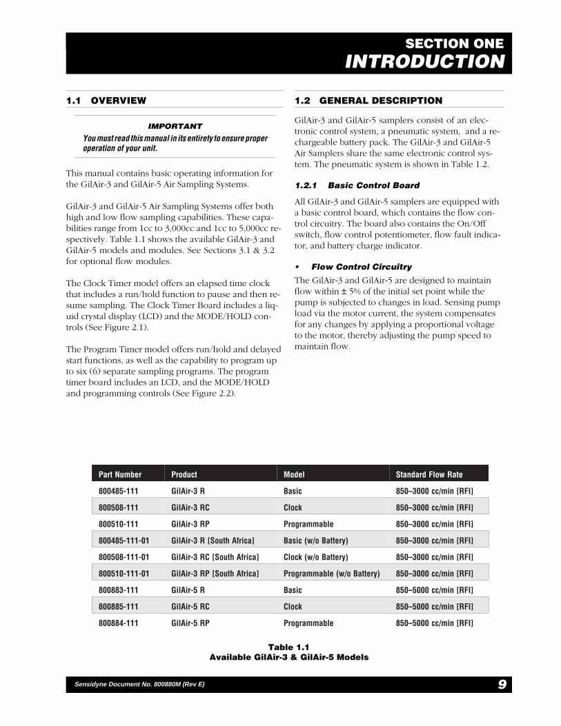
Table 1.1Available GilAir-3 & GilAir-5 Models
1.1 OVERVIEW
IMPORTANT
You must read this manual in its entirety to ensure properoperation of your unit.
This manual contains basic operating information forthe GilAir-3 and GilAir-5 Air Sampling Systems.
GilAir-3 and GilAir-5 Air Sampling Systems offer bothhigh and low flow sampling capabilities. These capa-bilities range from 1cc to 3,000cc and 1cc to 5,000cc re-spectively. Table 1.1 shows the available GilAir-3 andGilAir-5 models and modules. See Sections 3.1 & 3.2for optional flow modules.
The Clock Timer model offers an elapsed time clockthat includes a run/hold function to pause and then re-sume sampling. The Clock Timer Board includes a liq-uid crystal display (LCD) and the MODE/HOLD con-trols (See Figure 2.1).
The Program Timer model offers run/hold and delayedstart functions, as well as the capability to program upto six (6) separate sampling programs. The programtimer board includes an LCD, and the MODE/HOLDand programming controls (See Figure 2.2).
1.2 GENERAL DESCRIPTION
GilAir-3 and GilAir-5 samplers consist of an elec-tronic control system, a pneumatic system, and a re-chargeable battery pack. The GilAir-3 and GilAir-5Air Samplers share the same electronic control sys-tem. The pneumatic system is shown in Table 1.2.
1.2.1 Basic Control Board
All GilAir-3 and GilAir-5 samplers are equipped witha basic control board, which contains the flow con-trol circuitry. The board also contains the On/Offswitch, flow control potentiometer, flow fault indica-tor, and battery charge indicator.
• Flow Control Circuitry
The GilAir-3 and GilAir-5 are designed to maintainflow within ± 5% of the initial set point while thepump is subjected to changes in load. Sensing pumpload via the motor current, the system compensatesfor any changes by applying a proportional voltageto the motor, thereby adjusting the pump speed tomaintain flow.
rebmuNtraP tcudorP ledoM etaRwolFdradnatS
111-584008 R3-riAliG cisaB ]IFR[nim/cc0003–058
111-805008 CR3-riAliG kcolC ]IFR[nim/cc0003–058
111-015008 PR3-riAliG elbammargorP ]IFR[nim/cc0003–058
10-111-584008 ]acirfAhtuoS[R3-riAliG )yrettaBo/w(cisaB ]IFR[nim/cc0003–058
10-111-805008 ]acirfAhtuoS[CR3-riAliG )yrettaBo/w(kcolC ]IFR[nim/cc0003–058
10-111-015008 ]acirfAhtuoS[PR3-riAliG )yrettaBo/w(elbammargorP ]IFR[nim/cc0003–058
111-388008 R5-riAliG cisaB ]IFR[nim/cc0005–058
111-588008 CR5-riAliG kcolC ]IFR[nim/cc0005–058
111-488008 PR5-riAliG elbammargorP ]IFR[nim/cc0005–058

— PRELIMINARY —
Gilian® GILAIR-3 & GILAIR-5 AIR SAMPLING SYSTEMS
10 Sensidyne Document No. 800880M (Rev E)
• Flow Fault Indicator
The GilAir-3 and GilAir-5 Flow Fault Indicator lightsup if the pump is unable to maintain the flow ratewithin ± 5% of the set point. This can occur if thepump is operated outside its specified performanceranges, or when the battery pack has insufficientcharge. After 27–39 seconds of continuous operationunder fault conditions, the pump will stop. This delayis provided so that a momentary obstruction of flowwill not result in an unnecessary shutdown of the sys-tem. For units equipped with the optional timerboard, shutdown under fault conditions will preservethe run time in the display. This allows the user to sal-vage the sample data.
• Battery Charge Indicator
The battery charge indicator will illuminate when thesampler is turned on and the battery pack is fullycharged. Since the circuit is activated by the slight over-voltage condition common in a fully-charged battery,the indicator will normally turn off after the samplerruns for a short period of time.
1.2.2 Internal/External Vent Control
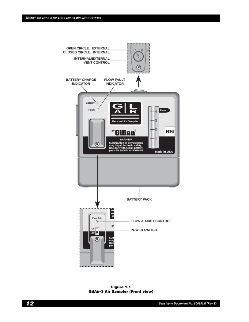
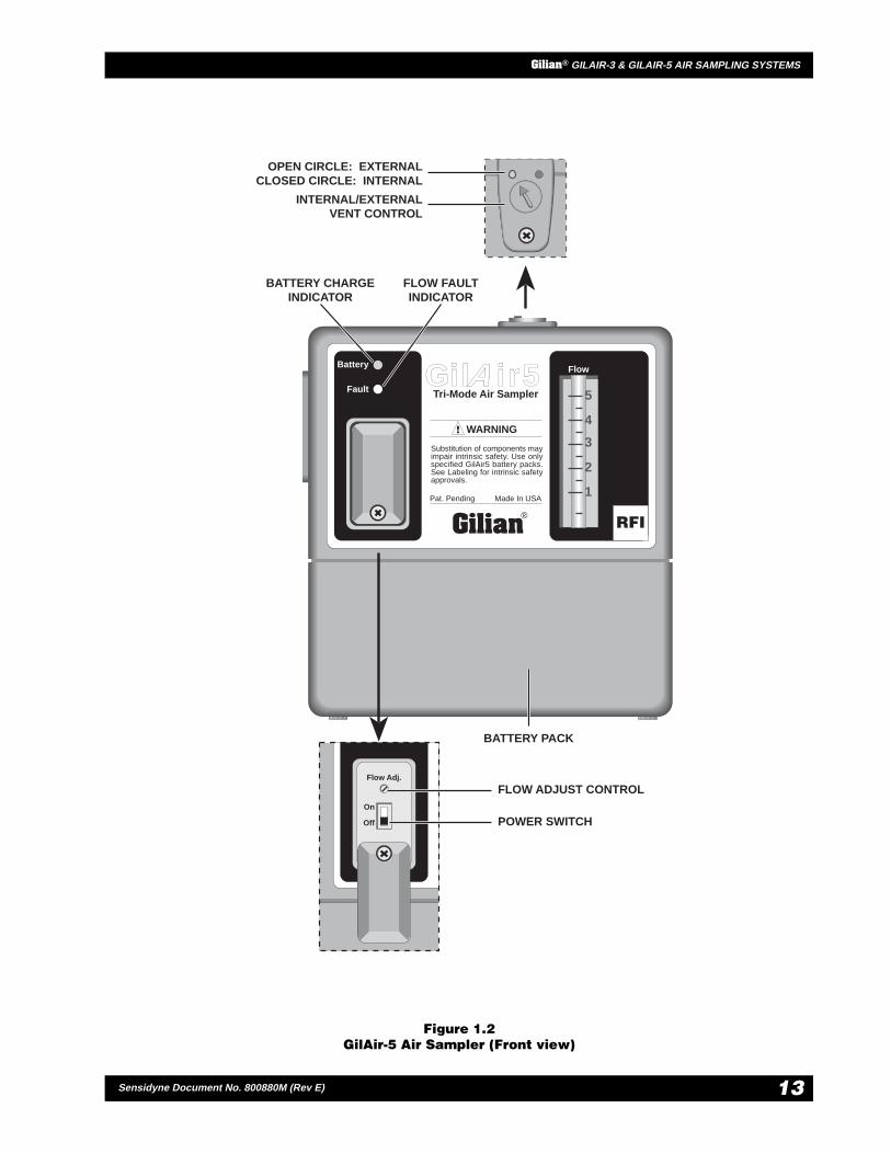
The internal/external vent control is located on thetop of the sampling pump. You may select the ventingcontrol as desired, using a screwdriver, provided withthe pump. Selecting the open circle position will bentthe pump’s discharge external to the sampler’s case(recommended for moist or corrosive sampling envi-ronments). Selecting the closed circle will vent thepump’s discharge internally (recommended for dustladen environments).
Table 1.2Pneumatic System
noitpircseD 3-riAliG 5-riAliG
pmupnotsipelgnis,nevirdrotomCD X
pmupnotsiplaud,nevirdrotomCD X
metsysgnivlavdedaol-erpdetnetaP X X
ylbmessarepmadlargetnI X X
ylbmessagnisuohretlifhguorht-eeS X X
)%02±:ycaruccA(rotacidniwolF/retematoR X X
wolFtnatsnoC:ytilibapaCwolFwoLlanoitpO X X
wolF-itluM:ytilibapaCwolFwoLlanoitpO X X
11
Gilian® GILAIR-3 & GILAIR-5 AIR SAMPLING SYSTEMS
Sensidyne Document No. 800880M (Rev E)
1.3 DISPLAY ICONS & MESSAGES
Available only on Clock Timer and Program TimerModels.
• Flashing Battery
A flashing battery icon indicates that the battery voltageis below its nominal value.
• Flashing Clock
A flashing clock icon indicates that the sampler is in theprogramming mode.
• Non-Flashing Clock
A non-flashing clock Icon indicates that the sampler isin the process of executing a sampling run.
• Display Letters
“D” Initial delay interval prior to starting thefirst sample interval.
“R” Run Time interval.
“D” + “R” Pause interval between Run Time inter-vals.
“C” Cycles. The number of times that the RunTime interval is performed.
“PC” Basic program which does the simpleTimer mode.
“P1” User-defined program.
“P2” User-defined program.
“P3” User-defined program.
“P4” User-defined program.
“P5” User-defined program.
“P6” User-defined program.“E” Programming error.
• Display Messages
“LAST” Flashes alternately with the data andicons of the last sampling run ex-ecuted.
“Old” Flashes alternately with the data andicons of the sampling run executedprior to the ”LAST” sampling run.
“SHUT”/”OFF” A reminder message to move the On/Off switch to the Off position to con-serve the battery charge. It indicatesthat 5 minutes have elapsed since: 1)a fault condition has terminated thesampling run, or 2) a programmedsampling run has reach completion(see Section 2.3.8).
“CAL” Flashes if the air sampler is preparedto run the pump without gatheringsampling data. Solid if the pump isrunning, to enable calibration of thesampler’s air flow rate.
• Fault Sampling Time
This number indicates the percentage of sampling timethat the pump ran while it was outside the 5% fault tol-erance envelope during the run. The number is locatedon the bottom right portion of the display.
— PRELIMINARY —
Gilian® GILAIR-3 & GILAIR-5 AIR SAMPLING SYSTEMS
12 Sensidyne Document No. 800880M (Rev E)
Figure 1.1GilAir-3 Air Sampler (Front view)
Battery
Fault
Gilian®by
Substitution of componentsmay impair intrinsic safety.Use only with Gilian batterypack PN 800464 or 800464-1.
WARNING
Made in USA
4
3
2
1
Flow
Personal Air Sampler
GA
LR
Pe
by
Subsmay Use pack
Flow Adj.
On
Off
RFI
INTERNAL/EXTERNALVENT CONTROL
OPEN CIRCLE: EXTERNALCLOSED CIRCLE: INTERNAL
BATTERY CHARGEINDICATOR
FLOW FAULTINDICATOR
FLOW ADJUST CONTROL
BATTERY PACK
POWER SWITCH
13
Gilian® GILAIR-3 & GILAIR-5 AIR SAMPLING SYSTEMS
Sensidyne Document No. 800880M (Rev E)
Figure 1.2GilAir-5 Air Sampler (Front view)
AWARNING
Gilian®
Pat. Pending Made In USA
Substitution of components mayimpair intrinsic safety. Use onlyspecified GilAir5 battery packs.See Labeling for intrinsic safetyapprovals.
Tri-Mode Air SamplerAGil ir5
Battery
Fault 5
4
3
2
1
FlowA
Flow Adj.
On
Off
INTERNAL/EXTERNALVENT CONTROL
OPEN CIRCLE: EXTERNALCLOSED CIRCLE: INTERNAL
BATTERY CHARGEINDICATOR
FLOW FAULTINDICATOR
FLOW ADJUST CONTROL
BATTERY PACK
POWER SWITCH
RFI
— PRELIMINARY —
Gilian® GILAIR-3 & GILAIR-5 AIR SAMPLING SYSTEMS
14 Sensidyne Document No. 800880M (Rev E)
SECTION TWOOPERATION
2.1 BASIC MODEL
2.1.1 Preparation
1. Charge the battery according to the Battery Main-tenance instructions in Section Four.
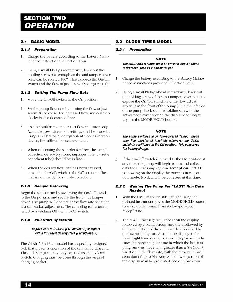
2. Using a small Phillips screwdriver, back out theholding screw just enough so the anti tamper coverplate can be rotated 180°. This exposes the On/Offswitch and the flow adjust screw (See Figure 1.1).
2.1.2 Setting The Pump Flow Rate
1. Move the On/Off switch to the On position.
2. Set the pump flow rate by turning the flow adjustscrew. (Clockwise for increased flow and counter-clockwise for decreased flow.
3. Use the built-in rotameter as a flow indicator only.Accurate flow adjustment settings shall be made byusing a Gilibrator 2, or equivalent flow calibrationdevice, for calibration measurements.
4. When calibrating the sampler for flow, the samplecollection device (cyclone, impinger, filter cassetteor sorbent tube) should be in-line.
5. When the desired flow rate has been attained,move the On/Off switch to the Off position. Theunit is now ready for sample collection.
2.1.3 Sample Gathering
Begin the sample run by switching the On/Off switchto the On position and secure the front anti-tampercover. The pump will operate at the flow rate set at thelast calibration adjustment. The sampling run is termi-nated by switching Off the On/Off switch.
2.1.4 Pull Start Operation
Applies only to GilAir-5 (PNº 800883-3) samplerswith a Pull Start Battery Pack (PNº 800869-7)
The GilAir-5 Pull Start model has a specially designedjack that prevents operation of the unit while charging.This Pull Start Jack may only be used as an ON/OFFswitch. Charging must be done through the originalcharging socket.
2.2 CLOCK TIMER MODEL
2.2.1 Preparation
NOTE
The MODE/HOLD button must be pressed with a pointedinstrument, such as a ball-point pen.
1. Charge the battery according to the Battery Mainte-nance instructions provided in Section Four.
2. Using a small Phillips-head screwdriver, back outthe holding screw of the anti-tamper cover plate toexpose the On/Off switch and the flow adjustscrew. (On the front of the pump.) On the left sideof the pump, back out the holding screw of theanti-tamper cover around the display opening toexpose the MODE/HOLD button.
NOTE
The pump switches to an low-powered “sleep” modeafter five minutes of inactivity whenever the On/Offswitch is positioned in the Off position. This conservesthe battery charge.
3. If the On/Off switch is moved to the On position atany time, the pump will begin to run and collectdata for a new sampling run. Exception: If “CAL”is showing on the display the pump is in calibra-tion mode. No data will be collected at this time.
2.2.2 Waking The Pump For “LAST” Run DataReadout
1. With the On/Off switch stiff Off, and using thepointed instrument, press the MODE/HOLD buttonto wake up the pump from its low-powered“sleep” state.
2. The “LAST” message will appear on the display,followed by a blank screen, and then followed bythe presentation of the run time data obtained bythe last sampling run. Also on the display in thelower right hand corner is a small digit which indi-cates the percentage of time in which the last sam-pling run was made with greater than ± 5% (fault)variation in the flow rate, with the maximum pre-sentation of up to 9%. Across the lower portion ofthe display may be presented one or more icons.

15
Gilian® GILAIR-3 & GILAIR-5 AIR SAMPLING SYSTEMS
Sensidyne Document No. 800880M (Rev E) 3.4
If the “CAL” display appears instead at this time,press the MODE/HOLD button twice more topresent the “LAST” run data.
Record the “LAST” run data at this time.
NOTE
If the On/Off switch is set to On at this point, the last rundata will be lost as a new sampling run is started.
3. After 5 minutes free of any button depression, thedisplay will blank as the sampler returns to the“sleep” mode. Return to Step 1 to reactivate theunit.
2.2.3 Setting The Pump Flow Rate
1. From the “LAST” presentation, pressing the MODE/HOLD button will change the display to a flashing“CAL” presentation.
2. Switch the On/Off switch to the On position. The“CAL” display will be steady.
3. Set the pump flow rate by turning the flow adjustscrew. (Clockwise for increased flow and counter-clockwise for decreased flow.
4. Use the built-in rotameter as a flow indicator only.Accurate flow adjustment settings shall be made byusing a Gilibrator 2, or equivalent flow calibrationdevice, for calibration measurements.
5. When calibrating the sampler for flow, the samplecollection device (cyclone, impinger, filter cassetteor sorbent tube) should be in-line.
6. When the desired flow rate has been attained,switch the On/Off switch to the Off position andreplace the left side anti-tamper cover if desired.The unit is now ready for sample collection.
2.2.4 Sample Gathering
Begin the sample run by switching the On/Off switchto the On position and secure the front anti-tampercover. The display will continuously show the elapsedsampling time for the sampling run, with the error per-centage and running icons also shown. The pump willoperate at the flow rate set at the last calibration adjust-ment.
2.2.5 HOLD (Pause) Feature
1. With the left side anti-tamper cover open (see Fig-ure 2.1), the sampling operation may be inter-rupted for breaks or lunches by pressing theMODE/HOLD button for at least 1 second. Thepump will stop and a “Hand” icon will appearflashing in the display window.
2. The sampling run can be resumed by pressing theMODE/HOLD button again. The “Hand” icon willbe removed from the display window.
2.2.6 Sampling Run Termination & Recovery
1. When the On/Off switch is moved to the Off posi-tion, the sampling run is terminated.
2. The accumulated run time minutes are displayedfor 5 more minutes, along with the icon (symbol)data. The unit then goes into “sleep” mode to con-serve the battery charge.
3. If you desire to exit the 5 minute run data displayto return to a blank display, perform a display self-test (Section 2.2.7). Then, follow the instructionsfor waking the pump (Section 2.2.2) to perform an-other action.
2.2.7 Display Self-Test
1. Whenever the On/Off switch is in the Off positionand the MODE/HOLD button is pressed continu-ously for at least three seconds, the sampler dis-play will show the unit’s program date code (e.g.,9644) for as long as the button is pressed.
2. Releasing the MODE/HOLD button will allow theself-test to begin, where all elements of the fivedigit positions will be individually displayed, fol-lowed by all five digits simultaneously countingfrom 1 through 9, then back down to 1.
3. Each display Icon will be individually displayedfrom right to left, followed by all the icons flash-ing twice before the display goes blank, terminat-ing the test.
4. The test runs for about 30 seconds, but can begreatly accelerated by pushing and holding theMODE/HOLD button depressed.
— PRELIMINARY —
Gilian® GILAIR-3 & GILAIR-5 AIR SAMPLING SYSTEMS
16 Sensidyne Document No. 800880M (Rev E)
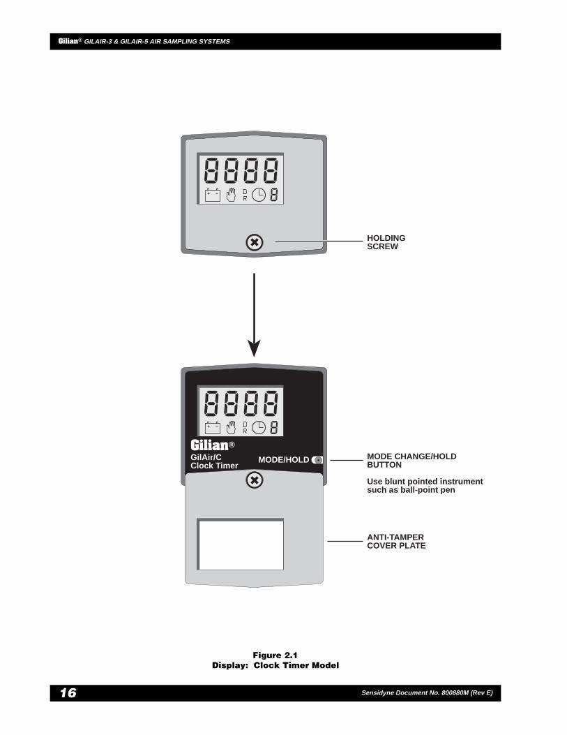
Figure 2.1Display: Clock Timer Model
MODE/HOLDGilAir/CClock Timer
Gilian®MODE CHANGE/HOLDBUTTON
Use blunt pointed instrumentsuch as ball-point pen
ANTI-TAMPERCOVER PLATE
HOLDINGSCREW
17
Gilian® GILAIR-3 & GILAIR-5 AIR SAMPLING SYSTEMS
Sensidyne Document No. 800880M (Rev E)
2.3 PROGRAM TIMER MODEL
NOTE
The Programming buttons should be pressed with a bluntpointed instrument, such as a ball-point pen.
Button Configuration (refer to Figure 2.2)
▲ Increase
▼ Decrease
PROG Program Select / Accept VariableValue Shown
MODE/HOLD Mode Change / Hold Operation
2.3.1 Preparation
1. Charge the battery according to Battery Mainte-nance Instructions provided in this Manual.
2. Using a small Phillips-head screwdriver, back outthe holding screw of the anti-tamper cover plate toexpose the On/Off switch and the flow adjustscrew. (On the front of the pump.) On the left sideof the pump, back out the holding screw of theanti-tamper cover around the display opening toexpose the MODE/HOLD, PROG, ▲, and ▼ but-tons.
NOTE
The pump switches to an low-powered “sleep” modeafter 5 minutes of inactivity whenever the On/Off switchis positioned in the Off position. This conserves thebattery charge.
3. If the On/Off switch is moved to the On position atany time, the pump will begin to run and collectdata for a new sampling run of the last-selectedprogram (see Section 2.3.8). Exception: If “CAL” isshowing on the display the pump is in calibrationmode and no data will be collected at this time.
2.3.2 Waking The Pump For “LAST” Run DataReadout
1. With the On/Off switch still Off, and using thepointed instrument, press the MODE/HOLD buttonto wake the pump up from its “sleep” state.
2. The “LAST” message will appear on the display,followed by a program number display, “Px” (“x”may be the letter C or 1 through 6), which is thenfollowed by the presentation of the run time dataobtained by the last sampling run. Also on the dis-play in the lower right hand corner is a small digitwhich indicates the percentage of time in whichthe last sampling run was made outside of the ± 5%(fault) variation in the flow rate, with the maximumpresentation of up to 9%. Across the lower portionof the display may be presented one or more icons.
If the “CAL” display appears instead at this time,press the MODE/HOLD button four more times topresent the “LAST” run data.
Record the “LAST” run data at this time.
NOTE
If the On/Off switch is set to On at this point to begin a newsampling run, the “LAST” run data will replace the “Old”run data, which will be lost at that time, as the last rundata is cleared for the new sampling run data. However,you may retrieve the “Old” run data later by pressing theMODE/HOLD button (with the On/Off switch in the Offposition) until the “Old” data are displayed.
3. After 5 minutes free of any button depression, thedisplay will blank as the sampler returns to the“sleep” mode. Return to Step 1 to reactivate theunit.
— PRELIMINARY —
Gilian® GILAIR-3 & GILAIR-5 AIR SAMPLING SYSTEMS
18 Sensidyne Document No. 800880M (Rev E)
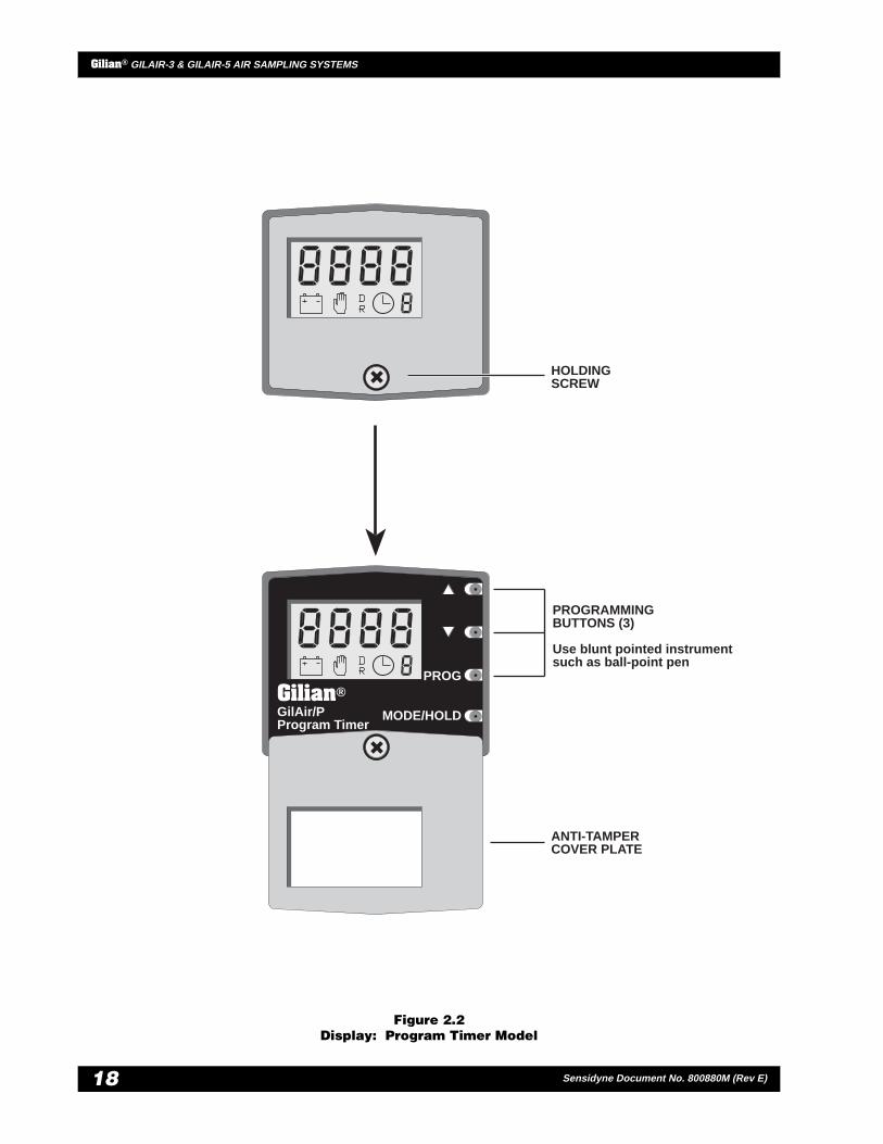
Figure 2.2Display: Program Timer Model
PROG
GilAir/PProgram Timer
Gilian®
MODE/HOLD
PROGRAMMINGBUTTONS (3)
Use blunt pointed instrumentsuch as ball-point pen
ANTI-TAMPERCOVER PLATE
HOLDINGSCREW
19
Gilian® GILAIR-3 & GILAIR-5 AIR SAMPLING SYSTEMS
Sensidyne Document No. 800880M (Rev E)
2.3.3 Setting The Pump Flow Rate
1. From the “LAST” presentation (which follows theblank display), press the MODE/HOLD button tochange the display to a flashing “CAL” presenta-tion.
2. Switch the On/Off switch to the On position. The“CAL” display will be steady.
3. Set the pump flow rate by turning the flow adjustscrew. (Clockwise for increased flow and counter-clockwise for decreased flow.
4. Use the built-in rotameter as a flow indicator only.Accurate flow adjustment settings shall be made byusing a Gilibrator 2, or equivalent flow calibrationdevice, for calibration measurements.
5. When calibrating the sampler for flow, the samplecollection device (cyclone, impinger, filter cassetteor sorbent tube) should be in-line.
6. When the desired flow rate has been attained,switch the On/Off switch to the Off position andreplace the left side anti-tamper cover if desired.The unit is now ready for sample collection.
2.3.4 Sample Gathering
From any pre-operation mode of the sampler, beginthe sampling run by switching the On/Off switch to theOn position and secure the front anti-tamper cover ifdesired. The pump will operate at the flow rate set atthe last calibration adjustment. For the first 20 secondsof the sampling run, the program number of the se-lected program will be shown as PC or P1 through P6.The display will thereafter continuously show theelapsed sampling time for the sampling run or the de-lay time until the next run time interval, with the errorpercentage and running icons also shown.
2.3.5 HOLD (Pause) Feature
1. With the left side anti-tamper cover open, the sam-pling operation may be interrupted for breaks orlunches by pressing the MODE/HOLD button for atleast 1 second. The pump will stop and a “Hand”symbol will appear flashing in the display window.
2. The sampling run can be resumed by pressing theMODE/HOLD button again. The “Hand” icon willbe removed from the display window.
2.3.6 Sampling Run Termination & Recovery
1. When the On/Off switch is moved to the Off posi-tion, the sampling run is manually terminated. Aprogrammed run (P1 through P6) will self-termi-nate upon completion if the On/Off Switch re-mains On.
2. The accumulated run time minutes are displayedfor 5 more minutes, along with the icon (symbol)data. The unit then goes into the “sleep” modewhen the On/Off switch is Off. If the switch is Onwhen a programmed run has been made, the“SHUT”/“OFF” display appears, and remains untilthe switch is turned Off.
3. If you desire to exit the 5 minute run data displayto return to a blank display, perform a display self-test (Section 2.3.7). Then, follow the instructionsfor waking the pump (Section 2.3.2) to perform an-other action.
2.3.7 Display Self-Test
1. Whenever the On/Off switch is in the Off positionand the MODE/HOLD button is pressed continu-ously for at least three seconds, the sampler dis-play will show the unit’s program date code (e.g.,9644) for as long as the button is pressed.
2. Releasing the MODE/HOLD button will allow theself-test to begin, where all elements of the fivedigit positions will be individually displayed, fol-lowed by all five digits simultaneously countingfrom 1 through 9, then back down to 1.
3. Each display Icon will be individually displayedfrom right to left, followed by all the icons flash-ing twice before the display goes blank, terminat-ing the test.
4. The test runs for about 30 seconds, but can begreatly accelerated by pushing and holding theMODE/HOLD button depressed.
— PRELIMINARY —
Gilian® GILAIR-3 & GILAIR-5 AIR SAMPLING SYSTEMS
20 Sensidyne Document No. 800880M (Rev E)
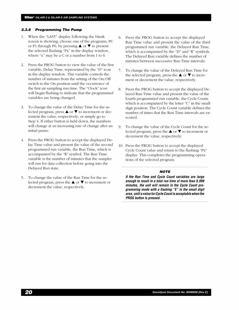
2.3.8 Programming The Pump
1. When the “LAST” display following the blankscreen is showing, choose one of the programs, PCor P1 through P6, by pressing ▲ or ▼ to presentthe selected flashing “Px” in the display window,where “x” may be a C or a number from 1 to 6.
2. Press the PROG button to view the value of the firstvariable, Delay Time, represented by the “D” iconin the display window. This variable controls thenumber of minutes from the setting of the On/Offswitch to the On position until the occurrence ofthe first air sampling run time. The “Clock” iconwill begin flashing to indicate that the programmedvariables are being changed.
3. To change the value of the Delay Time for the se-lected program, press ▲ or ▼ to increment or dec-rement the value, respectively, or simply go toStep␣ 4. If either button is held down, the numberswill change at an increasing rate of change after aninitial pause.
4. Press the PROG button to accept the displayed De-lay Time value and present the value of the secondprogrammed run variable, the Run Time, which isaccompanied by the “R” symbol. The Run Timevariable is the number of minutes that the samplerwill run for data collection before going into theDelayed Run state.
5. To change the value of the Run Time for the se-lected program, press the ▲ or ▼ to increment ordecrement the value, respectively.
6. Press the PROG button to accept the displayedRun Time value and present the value of the thirdprogrammed run variable, the Delayed Run Time,which is accompanied by the “D” and “R” symbols.The Delayed Run variable defines the number ofminutes between successive Run Time intervals.
7. To change the value of the Delayed Run Time forthe selected program, press the ▲ or ▼ to incre-ment or decrement the value, respectively.
8. Press the PROG button to accept the displayed De-layed Run Time value and present the value of thefourth programmed run variable, the Cycle Count,which is accompanied by the letter “C” in the smalldigit position. The Cycle Count variable defines thenumber of times that the Run Time intervals are ex-ecuted.
9. To change the value of the Cycle Count for the se-lected program, press the ▲ or ▼ to increment ordecrement the value, respectively.
10. Press the PROG button to accept the displayedCycle Count value and return to the flashing “Px”display. This completes the programming opera-tions of the selected program.
NOTE
If the Run Time and Cycle Count variables are largeenough to result in a total run time of more than 9,999minutes, the unit will remain in the Cycle Count pro-gramming mode with a flashing “E” in the small digitarea, until a value for Cycle Count is acceptable when thePROG button is pressed.
21
Gilian® GILAIR-3 & GILAIR-5 AIR SAMPLING SYSTEMS
Sensidyne Document No. 800880M (Rev E)
SECTION THREEFLOW OPERATION
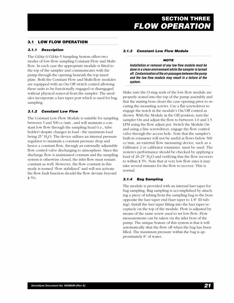
3.1 LOW FLOW OPERATION
3.1.1 Description
The GilAir-3/GilAir-5 Sampling System offers twomodes of low-flow sampling Constant Flow and Multi-flow. In each case the appropriate module is fitted tothe top of the sampler and communicates with thepump through the opening beneath the top insertplate. Both the Constant Flow and Multi-flow modulesare equipped with an On/Off switch control allowingthese units to be functionally engaged or disengagedwithout physical removal from the sampler. The mod-ules incorporate a luer taper port which is used for bagsampling.
3.1.2 Constant Low Flow
The Constant Low Flow Module is suitable for samplingbetween 5 and 500 cc/min , and will maintain a con-stant low flow through the sampling head (i.e., tubeholder) despite changes in load - the maximum loadbeing 25” H2O. The device utilizes an internal pressureregulator to maintain a constant pressure drop andhence a constant flow, through an externally adjustableflow control valve discharging to atmosphere. Since thedischarge flow is maintained constant and the samplingsystem is otherwise closed, the inlet flow must remainconstant as well. However, the flow constant in thismode is termed “flow stabilized” and will not activatethe flow fault function should the flow deviate beyond± 5%.
3.1.3 Constant Low Flow Module
NOTE
Installation or removal of any low flow module must bedone in a clean environment while the sampler is turnedoff. Contamination of the air passages between the pumpand the low flow module may result in a failure of thesystem.
Make sure the O-ring seals of the low flow module areproperly seated into the top of the pump assembly andthat the mating boss clears the case opening prior to se-curing the mounting screws. Use a flat screwdriver toengage the notch in the module’s On/Off control asshown. With the Module in the Off position, turn thesampler On and adjust the flow to between 1.0 and 1.5LPM using the flow adjust pot. Switch the Module Onand using a fine screwdriver, engage the flow controlvalve through the access hole. Note that the sampler’sbuilt-in rotameter will not be useful at flows below 500cc/min, an external flow measuring device, such as aGilibrator 2 or calibrator rotameter, must be used. Thesystem’s performance should be checked by applying aload of 20-25” H2O and verifying that the flow recoversto within ± 5%. Note that at very low flow rates it maytake several minutes for the flow to recover. This isnormal.
3.1.4 Bag Sampling
The module is provided with an internal luer taper forbag sampling. Bag sampling is accomplished by attach-ing a piece of tubing from the sampling bag to the bossopposite the luer taper end (luer taper to 1/8” ID tub-ing). Install the luer taper fitting into the luer taper re-ceptacle on the top of the module. Flow is adjusted bymeans of the same screw used to set low flow. Flowmeasurements can be taken via the inlet boss of thepump. The unique feature of this system is that it willautomatically shut the flow off when the bag has beenfilled. The maximum pressure within the bag is ap-proximately 8” of water.

— PRELIMINARY —
Gilian® GILAIR-3 & GILAIR-5 AIR SAMPLING SYSTEMS
22 Sensidyne Document No. 800880M (Rev E)
3.2 MULTI-FLOW OPERATION
3.2.1 Multi-Flow Module
The multi-flow module is suitable for multiple tubesampling between 1 and 750 cc/min and can be usedin conjunction with the Gilian Universal Tube HolderSystem to perform multiple tube sampling. Themodule’s internal regulator maintains a constant pres-sure of approximately 18” H2O at the sampler’s inletwhile allowing changes in total flow through the sys-tem. With a constant pressure in the tube holder mani-fold, the flow through each tube can be set indepen-dently without affecting the flow(s) through the adja-cent tube(s). Total sampling tube combined flows can-not exceed 750 cc/min.
The multi-flow module is installed in the same manneras the Constant Flow Module. Once installed, set themodule’s On/Off switch to the Off position and adjustthe sampler’s flow to between 1 and 1.5 LPM. Set themodule On/Off control to the On position. Perfor-mance should be checked in conjunction with the testset-up. With the load valve closed, the pressure shouldbe 18” ± 3” H2O. Open the load valve until the flow isapproximately 750 cc/min. The pressure should notvary more than ± 3” H2O.
Once the system’s performance has been checked, theTube Holder System can be connected. Fit each sor-bent tube to an appropriately sized Tube Holder andconnect the outlet of the Manifold to the inlet of thesample. Set the flow through each tube by adjusting thecorresponding flow control valve in the Manifold. Theflow through each tube should be measured with acalibrated device connected to the inlet of that tubeholder. A Gilibrator 2 or conventional bubble flowmeter is preferable since the pressure drop through thistype of device is negligible.
3.2.2 Bag Sampling
A unique multi-flow bag sampling capability is avail-able in the latest version of the multi-flow module. Ac-cess to the pressure port is by means of an internal luertaper on top of the module. One or more bags may befilled by installing the luer fitting into the luer taper re-ceptacle located on top of the module and connectinga 1/4” tubing from the opposite end of the luer fitting(luer taper from 1/8” ID tubing) to the flow manifold.
Flow is adjusted by means of the flow control valve inthe manifold. Connection to the bag is made by screw-ing the end fittings to the tubing housing such that theO-rings located on the shoulder of the fitting sealsagainst the tube housing. An additional piece of 1/8” IDtubing is secured to the special fitting on the manifoldwhich is then directed to the bag. Flow can be set viaa Gilibrator 2 or flow meter by adjusting the screwwithin the specific tube housing associated with theflow control valve so as to obtain the flow required.Remove the calibration equipment and connect thetubing to the bag to be filled.

23
Gilian® GILAIR-3 & GILAIR-5 AIR SAMPLING SYSTEMS
Sensidyne Document No. 800880M (Rev E)
SECTION FOURBATTERY MAINTENANCE
4.1 SERVICE OVERVIEW
Battery packs for Gilian air sampling pumps are re-chargeable Nickel Cadmium batteries. They must befully charged and maintained properly to achieve maxi-mum pump run time. It is incumbent upon the pumpuser to ensure that the battery has enough charge tocomplete the intended run time.
Rechargeable Batteries
• GilAir-3: 4.8 Volt, 1.8 Ampere-hours
• GilAir-5: 6.0 Volt, 1.8 Ampere-hours
The battery packs for the GilAir-3 and GilAir-5 arecharged through a built-in jack, on the side of the bat-tery pack. The batteries may be charged while in placeor while removed from the sampler. Note that thecharging plug is polarized to prevent improper inser-tion. Do not short the battery terminals or the chargingjack. Shorting will result in irreversible damage to thebattery pack.
NOTE
Battery packs for South African versions are customersupplied. These must be rated 4.8V, 1.8 ampere-hours.
Table 4.1Estimated Battery Life
egasUpmuP esUylkeeW *efiLyrettaB.tsE
hgiH sruoh06–04 sraey5.1–1
muideM sruoh93–02 sraey5.2–5.1
woL sruoh02< sraey5.2revo
.yrettabmuimdac-lekcinehtfoefilehtnetrohsyamsdoirepdednetxe*
4.1.1 Battery Life
Battery life is usually measured in charge/dischargecycles. Gilian battery packs are capable of providingbetween 300 and 500 charging cycles. Since this isvery difficult to track over the life of the battery, thefollowing guide will help you to anticipate how longthe battery should last.
The estimated battery life is based on proper batterymaintenance. The best way to ensure maximum bat-tery life is to track daily pump usage and only chargethe battery pack when necessary.
4.1.2 Memory Effect
Nickel-Cadmium batteries will develop reduced capac-ity when the user does not maintain the practice of dis-charging or charging fully during the sampling process.Memory effect takes time to develop and usually canbe eliminated with two discharge/charge cycles(Double Evaluation mode on the BMS charger).
4.1.3 Leakage Current
Nickel-Cadmium batteries always have a small internalleakage current. If the battery pack has been removedfrom the charger for more than two days without use, itwill require additional charging to restore it to full ca-pacity. This process can be repeated two or three timeswithout causing signs of memory effect.
— PRELIMINARY —
Gilian® GILAIR-3 & GILAIR-5 AIR SAMPLING SYSTEMS
24 Sensidyne Document No. 800880M (Rev E)
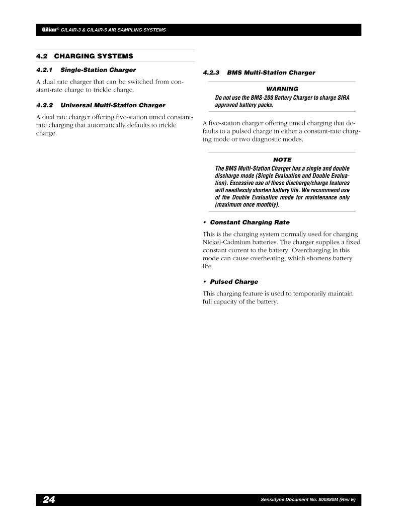
4.2 CHARGING SYSTEMS
4.2.1 Single-Station Charger
A dual rate charger that can be switched from con-stant-rate charge to trickle charge.
4.2.2 Universal Multi-Station Charger
A dual rate charger offering five-station timed constant-rate charging that automatically defaults to tricklecharge.
4.2.3 BMS Multi-Station Charger
WARNING
Do not use the BMS-200 Battery Charger to charge SIRAapproved battery packs.
A five-station charger offering timed charging that de-faults to a pulsed charge in either a constant-rate charg-ing mode or two diagnostic modes.
NOTE
The BMS Multi-Station Charger has a single and doubledischarge mode (Single Evaluation and Double Evalua-tion). Excessive use of these discharge/charge featureswill needlessly shorten battery life. We recommend useof the Double Evaluation mode for maintenance only(maximum once monthly).
• Constant Charging Rate
This is the charging system normally used for chargingNickel-Cadmium batteries. The charger supplies a fixedconstant current to the battery. Overcharging in thismode can cause overheating, which shortens batterylife.
• Pulsed Charge
This charging feature is used to temporarily maintainfull capacity of the battery.

25
Gilian® GILAIR-3 & GILAIR-5 AIR SAMPLING SYSTEMS
Sensidyne Document No. 800880M (Rev E)
APPENDIX APARTS LIST
.oNtraP noitpircseD
815008 )eulB(wolFtnatsnoC,eludoMwolFwoL,5-riAliG/3-riAliG
1-815008 )kcalB(wolFtnatsnoC,eludoMwolFwoL,5-riAliG/3-riAliG
915008 )eulB(wolF-itluM,eludoMwolFwoL,5-riAliG/3-riAliG
1-915008 )kcalB(wolF-itluM,eludoMwolFwoL,5-riAliG/3-riAliG
2-023008 tiKrotcirtseRdnassobriA,5-riAliG/3-riAliG
211008 tiKlooT,5-riAliG/3-riAliG
M088008 launaMecivreS&noitarepO5-riAliG/3-riAliG
464008 )eulB(kcaPyrettaB,3-riAliG
1-464008 )kcalB(kcaPyrettaB,3-riAliG
4-464008 )ailartsuA(kcaPyrettaB,3-riAliG
5-464008 )acirfAhtuoS(stnenopmoCllehSkcaPyrettaB,3-riAliG
968008 )eulB(kcaPyrettaB,5-riAliG
1-968008 )kcalB(kcaPyrettaB,5-riAliG
7-968008 )tratSlluP(kcaPyrettaB,5-riAliG
510004 M5.2,kcaJtratSlluP
941008 mm07x6)dlofinaMoN(yssAredloHebuTelgniS,tiKredloHebuT
841008 mm07x6)gnibuT/sdnE/sredloH(dlofinaMlauD,tiKredloHebuT
704108 mm011x01)gnibuT/sdnE/sredloH(dlofinaMlauD,tiKredloHebuT
484002 DI"4/1,"63,gnibuT
951008 )retpadADI"4/1htiw(DI"8/1,"63,gnibuT
505002 DI"8/1,"63,gnibuT
* For further information on Gilian spare parts, please contact yourSensidyne Customer Service Representative at 800-451-9444, ext782.
— PRELIMINARY —
Gilian® GILAIR-3 & GILAIR-5 AIR SAMPLING SYSTEMS
26 Sensidyne Document No. 800880M (Rev E)
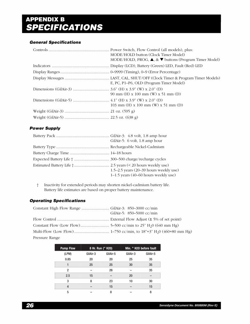
APPENDIX BSPECIFICATIONS
General Specifications
Controls ......................................................... Power Switch, Flow Control (all models), plus:MODE/HOLD button (Clock Timer Model)MODE/HOLD, PROG, ▲, & ▼ buttons (Program Timer Model)
Indicators ...................................................... Display (LCD), Battery (Green) LED, Fault (Red) LED
Display Ranges .............................................. 0–9999 (Timing), 0–9 (Error Percentage)
Display Messages .......................................... LAST, CAL, SHUT/OFF (Clock Timer & Program Timer Models)E, PC, P1–P6, OLD (Program Timer Model)
Dimensions (GilAir-3) .................................. 3.6” (H) x 3.9” (W) x 2.0” (D)90 mm (H) x 100 mm (W) x 51 mm (D)
Dimensions (GilAir-5) .................................. 4.1” (H) x 3.9” (W) x 2.0” (D)103 mm (H) x 100 mm (W) x 51 mm (D)
Weight (GilAir-3) .......................................... 21 oz. (595 g)
Weight (GilAir-5) .......................................... 22.5 oz. (638 g)
Power Supply
Battery Pack .................................................. GilAir-3: 4.8 volt, 1.8 amp hourGilAir-5: 6 volt, 1.8 amp hour
Battery Type .................................................. Rechargeable Nickel-Cadmium
Battery Charge Time ..................................... 14–18 hours
Expected Battery Life † ................................. 300–500 charge/recharge cycles
Estimated Battery Life † ................................. 2.5 years (< 20 hours weekly use)1.5–2.5 years (20–39 hours weekly use)1–1.5 years (40–60 hours weekly use)
† Inactivity for extended periods may shorten nickel-cadmium battery life.Battery life estimates are based on proper battery maintenance.
Operating Specifications
Constant High Flow Range .......................... GilAir-3: 850–3000 cc/minGilAir-5: 850–5000 cc/min
Flow Control ................................................. External Flow Adjust (± 5% of set point)
Constant Flow (Low Flow)........................... 5–500 cc/min to 25” H20 (640 mm Hg)
Multi-Flow (Low Flow) ................................. 1–750 cc/min, to 18”+3” H20 (460+80 mm Hg)
Pressure Range
wolFpmuP )02H”(nuR.rH8 tluaferofebO2H”.niM
)MPL( 3-riAliG 5-riAliG 3-riAliG 5-riAliG
58.0 02 02 52 53
1 52 52 03 53
2 – 62 – 53
5.2 51 – 02 –
3 8 32 01 03
4 – 51 – 51
5 – 8 – 8

27
Gilian® GILAIR-3 & GILAIR-5 AIR SAMPLING SYSTEMS
Sensidyne Document No. 800880M (Rev E)
APPENDIX CTROUBLESHOOTING GUIDE
esuaC ydemeR
".E"dnanocidnahswohsyalpsid,noitisopnOotdevomsihctiwsffO/nOnehW•
.melborperawtfoS nehtdnanoitisopffOothctiwsffO/nOevoM.noitisopnOotkcab
.dellatsnisikcapyrettabnehwyalpsiDlausunU•
.dellatsniylreporptonkcapyrettaB .ylreporptillatsni-erdnakcapyrettabtcennocsiD

— PRELIMINARY —
Gilian® GILAIR-3 & GILAIR-5 AIR SAMPLING SYSTEMS
28 Sensidyne Document No. 800880M (Rev E)
APPENDIX DRETURNED MATERIAL AUTHORIZATION
SERVICE OPTIONS
The Gilian Service Department offers you a variety of service options which will help increase youruser confidence while minimizing costly interruptions and maintenance costs. These options includeinitial training, on-site technical assistance, and full factory repairs. Gilian has developed severalprograms which will allow you to select just the right options best suited to your applications andneeds. For further information, contact the Gilian Service Department.
policy is to perform all needed repairs to restore theinstrument to its full operating condition.
Repairs are handled on a “first in - first out” basis. Yourorder may be expedited if you authorize an expeditingfee. This will place your order next in line behind or-ders currently in process.
Pack the instrument and its accessories (preferably intheir original packing) and enclose your return address,purchase order, shipping and billing information, RMAnumber, a description of the problem encounteredwith your instrument and any special instructions. Allprices are subject to change without notice.
If this is the first time you are dealing directly with thefactory, you will be asked to prepay or to authorize aCOD shipment.
Send the instrument, prepaid, to:
SENSIDYNE16333 BAY VISTA DRIVE
CLEARWATER, FL 33760 USA
ATTENTION: Service Department
RMA #:_______________________
Gilian maintains an instrument service facility at thefactory to provide its customers with both warranty andnon-warranty repair service. Gilian assumes no liabilityfor service performed by personnel other than Gilianpersonnel. To facilitate the repair process, please con-tact the Gilian Service Department in advance for assis-tance with a problem which cannot be remedied and/or requires the return of the product to the factory. Allreturned products require a Returned Material Authori-zation (RMA) number. Gilian Service Department per-sonnel may be reached at:
Sensidyne16333 Bay Vista Drive
Clearwater, FL 33760 USA727-530-3602
727-539-0550 [FAX]
All non-warranty repair orders will have a minimum feewhether the repair is authorized or not. This fee in-cludes handling, administration and technical expensesfor inspecting the instrument and providing an esti-mate. However, the estimate fee is waived if the repairis authorized.
If you wish to set a limit to the authorized repair cost,state a “not to exceed” figure on your purchase order.Please indicate if a price quotation is required beforeauthorization of the repair cost, understanding that thisinvokes extra cost and handling delay. Gilian’s repair


16333 Bay Vista Dr. • Clearwater, Florida 33760 • (800) 451-9444 • (727) 530-3602 • (727) 539-0550 [FAX] • www.sensidyne.com