gkn mim technology - gkngroup.com library/capabilities... · technology is particularly suitable...
TRANSCRIPT

MIM Technology
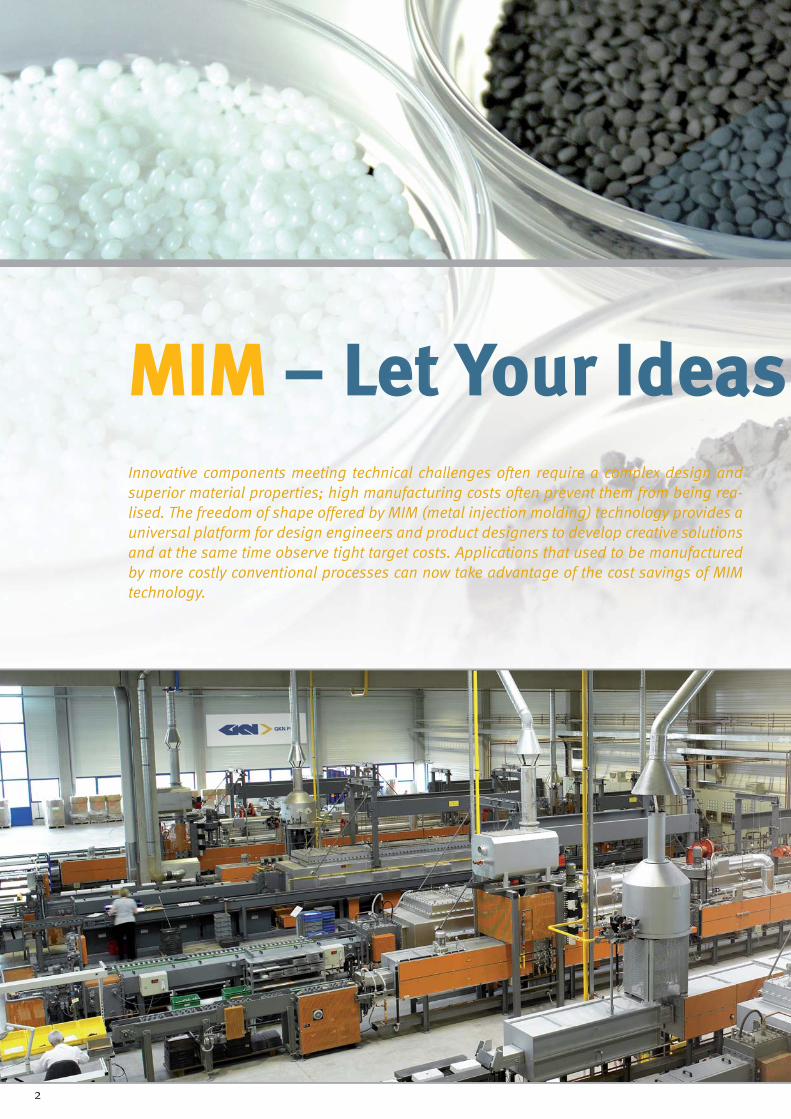
MIMMIM – Let Your Ideas Come True– Let Your Ideas Innovative components meeting technical challenges often require a complex design and superior material properties; high manufacturing costs often prevent them from being rea-lised. The freedom of shape offered by MIM (metal injection molding) technology provides a universal platform for design engineers and product designers to develop creative solutions and at the same time observe tight target costs. Applications that used to be manufactured by more costly conventional processes can now take advantage of the cost savings of MIM technology.
2

MIM – Let Your Ideas Come TrueCome TrueMIM components combine the outstanding material proper-ties of metal and the complex design options of plastic tech-nology. Shaping by the injection molding of metal powders (MIM) offers maximum freedom with respect to part geometry and material options far exceeding the design possibilities of machining and casting technologies.
Undercuts, bores and blind holes can be formed in any direc-tion. Wall thickness of 1 mm or less as well as bore diameters of just a few tenths of a millimetre can be realised.
Relief-like structures and engravings such as company logos or identifi cation marks can be produced in detail. Even the use of expensive high strength alloys, corrosion resistant and other premium steels is possible as no additional machining costs are incurred.
MIM components achieve an excellent surface fi nish (usually surface roughness values Ra < 1 µm) without any subsequent operations. The microstructure of the sintered components allows electroplating and electro-polishing without any pre-treatment.
The depth of penetration after case hardening is comparable to the values of forged steels. MIM materials are usually weld-able too.
3

MIMMIM – Enjoy the Benefi ts– Enjoy the Benefi ts
The benefi ts of MIM processing can best be exploi-ted if MIM design concepts are employed in the development phase. Entirely new possibilities for dimensional and shape design are opened to the design engineer.
High volume production of highly complex components is economical due to fully automatic MIM processing and yields process reliabilities conforming even to the strict re-quirements of the automotive industry
The fl exible geometric design can even be applied to high strength metals and premium steels
Applications of plastics, aluminium, or zinc die castings whose loading conditions are at the limit can be replaced by high strength MIM parts
Costly joining or assembling techniques can be avoided by designing complex MIM components that can replace two or even more assembled parts
Threads can be produced in the primary shaping process (ie injection molding)
Material and costs can be saved by optimising the part vo-lume. Weight reduction leads to further savings for dynami-cally loaded components in the form of a reduced moment of inertia
The most intricate geometries are exactly reproduced in de-tail
Even innovative alloy materials according to specifi c custo-mer requirements can be economically processed
Metal injection molding technology offers virtually unlimited design freedom to the design engineer – these are just a few examples of the possible variety of shapes.
4

MIMMIM – Its Strengths in Summary
3 dimensional complexity:
The forming process of MIM technology is closely related to traditional plastic injection molding and thus allows the same level of complexity in a regard to the design geometries.Parts with bore holes, blind holes, slots, notches, inner and outer threads, recesses, undercuts, structured surfaces, and cavities are made by MIM without problems. Similarly sophis-ticated design elements are not feasible with alternative chip-less shaping processes.
Weight reduction:
Optimum part design allows for weight reduction without lo-sing functionality. Weight reduction has a positive effect on the cost of the fi nished product.
High productivity:
When large numbers of identical parts are required, the cost advantage of MIM technology is particularly evident. Depen-ding on the application, even highly complex components can be made without costly fi nishing operations. This is why this technology is particularly suitable for high volume produc-tion.
sional complexity:3 dimens
5

MIM MIM – A Highly Technical Manu-– A Highly Technical Manu-facturing Processfacturing Process1.) Feedstock preparation
For the preparation of the feedstock, metal powders are fi rst blended according to the desired alloy composition. Then thermoplastic polymers and additives are kneaded with the powder mix and heated to obtain a viscous mass. The mass is then cooled down and processed into granular pellets (feed-stock).
The metal powder alloy determines the mechanical and che-mical properties achieved by the fi nished product. GKN engi-neers have excellent know-how for powder development as well as for controlling the feedstock properties achieved.
2.) Injection molding
Thermoplastics injection molding machines with special mo-difi cations are used in MIM technology, similar process as ap-plied in conventional plastics injection molding. After being dosed and fed into the injection unit the input ma-terial (feedstock) is molten and densifi ed in front of the screw-conveyor. By a forward movement of the screw the plasticized mass is injected with high pressure through a sprue and run-ner system into the individual cavities of the mold.
Subsequently the mass is 'frozen' inside the mold cavities with their geometric design ('green compact'). After cooling down to the ejection temperature the mold is opened along the parting plane. The solidifi ed parts, ie the green compacts, are ejected from their cavities by means of ejection pins and can then be removed by suitable handling systems.
6
MIM MIM – Metal Injection Molding– Metal Injection Molding
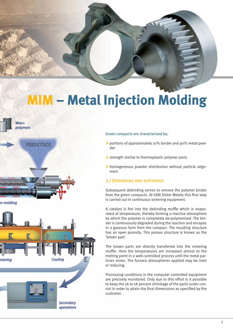
Green compacts are characterised by:
portions of approximately 10% binder and 90% metal pow-der
strength similar to thermoplastic polymer parts
homogeneous powder distribution without particle align-ment
3.) Debinding and sintering
Subsequent debinding serves to remove the polymer binder from the green compacts. At GKN Sinter Metals this fi rst step is carried out in continuous sintering equipment.
A catalyst is fed into the debinding muffl e which is evapo-rated at temperature, thereby forming a reactive atmosphere by which the polymer is completely de-polymerised. The bin-der is continuously degraded during the reaction and escapes in a gaseous form from the compact. The resulting structure has an open porosity. This porous structure is known as the 'brown part'.
The brown parts are directly transferred into the sintering muffl e. Here the temperatures are increased almost to the melting point in a well-controlled process until the metal par-ticles sinter. The furnace atmospheres applied may be inert or reducing.
Processing conditions in the computer controlled equipment are precisely monitored. Only due to this effort is it possible to keep the 16 to 18 percent shrinkage of the parts under con-trol in order to attain the fi nal dimensions as specifi ed by the customer.
7

Heat treatment Hardening, tempering, quenching and tempering, surface harde-ning, case hardening
Physicochemical surface treatment
Nitriding, carbonitriding, nitrocar-burizing, boriding, siliciding
Chemical surface treatment Pickling, chemical deburring, burnishing, etching
Mechanical surface treat-ment
Engraving, barrel fi nishing, grin-ding, polishing, deburring, shot peening
Applying nonmetallic anor-ganic coatings
Chromatising, phosphating, anodizing, enamelling
Applying metallic coatings Electroplating, chemical metal coating, melt dip coating, metal spraying, chromizing
Applying organic coatings Printing, adhesive bonding, varnishing
Applying wear resistant coatings
CVD coating, PVD coating
MIMMIM –– Secondary ProcessingSecondary Processing
MIM components can be further processed and en-hanced in many ways. Among others, the following processes may be applied:
8

MIM MIM - Dimensional - Dimensional TolerancesTolerances
Typical tolerances of sintered MIM components
The standard dimensional tolerances given in the adjoining table are generally achieved after sintering with considerati-on of the 16 to 18 percent shrinkage. These standard values are just guidelines since the real di-mensional tolerances depend on the geometry and material composition and therefore can easily vary.If even closer dimensional tolerances are required, these can sometimes be achieved by re-designing the MIM com-ponent.In addition to that, GKN offers a variety of chipless and chip-ping fi nishing operations in order to conform to the highest requirements.
MIM – compared to competing technologies
If the strengths and benefi ts of MIM technology are employed at the design stage, substantial advantages can be achieved over almost all conventional technologies. These are usually refl ected as improved function and enormous cost savings.MIM paves the way to simplify entire component assemblies by reducing the number of individual parts. This helps to re-duce the sources of error in the manufacturing process, en-hance process reliability and thus guarantee higher quality.
Résumé: MIM technology proves economical where complex shaped components with close dimensional tolerances, de-manding mechanical properties and excellent surface fi nish are required.
MIM dimensional tolerances*[mm]
Nominal dimension X[mm]
Standard tolerance[mm]
Up to 3 +/- 0,05
3 <x> 6 +/- 0,06
6 <x> 15 +/- 0,075
15 <x> 30 +/- 0,15
30 <x> 60 +/- 0,25
(* Given tolerances serve as guidelines)
press-sinter
die casting
machining investment casting
low average high
Part Complexity
Part
s /
Year
9

MIMMIM - Guidelines for Part - Guidelines for Part DesignDesignIn order to fully exploit the inherent potential of MIM technology, these guidelines for part design should be observed at the earliest possible design stage.We have compiled the most important design prin-ciples in the following graphics – for optimum MIM design from the beginning!
Example: fi xture
Flat bottom face
MIM components exhibit about 16 to 18 percent shrinkage du-ring the debinding and sintering process and therefore requi-re a sliding bottom surface.
Ideally a fl at bottom face should be designed for suffi cient part stablility. This can help to avoid distortion and resulting subsequent leveling costs.
Threads
Inner threads that are planned in the design stage can be shaped by MIM in the primary shaping process, provided they are designed adequately and can be realised by so-called „spinning cores“.
10

Example: linking block
Constant wall thickness
If possible, the wall thickness should be constant all over the part and abrupt wall changes should be avoided. This guaran-tees a uniform mold fi ll during injection molding.
Ribs and links
Ribs and links serve to stiffen the part and mainly improve the strength of the MIM component. These design elements can also be used to improve the dimensional accuracy.
Example: shaft guide
Radii
The use of radii on edges, for example, has several positive effects on the overall picture of the MIM component. Not only are handling and aesthetic appearance of the fi nished parts improved, but also the material costs can be reduced. Round-ed edges improve the strength, too, as the load is better dis-tributed.
Weight reduction
Weight reduction can best be realised by creating free space in the MIM component. Besides reducing the weight of the component, the reduction of material cost also leads to a lower sales price of the part.Further the dynamic properties of the component can also be improved.
11

About GKN Sinter Metals
GKN Sinter Metals – a wholly ownedsubsidiary of U.K.-based GKN plc,a global industrial company – is theworld’s largest producer of precisionpowder metal products. With a focuson superior delivery, quality and totalsolutions, the company offersextensive technical expertise indesign, testing and various processtechnologies. GKN Sinter Metalsoffers a full range of more than10,000 complex shape, highstrengthproducts for the automotive,commercial vehicle, homeappliance, lawn and garden, offi ceequipment, power tool, recreationalvehicle and process industry markets.The company’s global footprintspans more than 13 countriesacross fi ve continents. GKN SinterMetals is in close proximity to itscustomers with more than 30 globallocations and a workforce ofapproximately 5,500 employees.
For more information about GKN’sworld of solutions visit www.gknsintermetals.com
Production Plants
ArgentinaGKN Sinter Metals de Argentina S.A.Ruta Nac. 5 Km. 159,5(B6622GKA) Chivilcoy – Bs. As.Argentina
Phone: *54-11-5368-3700E-mail: [email protected]
BrazilGKN Sinter Metals Ltda.Av. Emancipacão, 4.500 - Santa EsmeraladaCEP 13186-542Hortolandia – SP – Brazil
Phone: *55-19-2118-9400E-Mail: [email protected]
CanadaGKN Sinter Metals – St. Thomas Ltd.7 Michigan BoulevardSt. Thomas, OntarioCanada N5P 1H1
Phone: *1-519-631-4880E-mail: [email protected]
ChinaGKN Sinter Metals – DanyangNumber 7 Mechanical Industry ParkDanyang Development ZoneDanyang, China
Phone: *86-511-86-885-556E-mail: [email protected]
GermanyGKN Sinter Metals Engineering GmbHKrebsöge 1042 477 RadevormwaldGermany
Phone : *49 2191-693-0E-mail : [email protected]
GKN Sinter Metals Filters GmbHDahlienstraße 43P.O.Box 152042 477 RadevormwaldGermany
Phone: *49 2195-609-27E-Mail: feedback@gkn-fi lters.com
IndiaGKN Sinter Metals Ltd.146, Mumbai Pune RoadPimpri, Pune 411 018 Maharashtra, India
Phone: *91-20-2742-6261, 6262, 6263E-mail: [email protected]
ItalyGKN Sinter Metals SpAFabrikstraße 539 031 Bruneck (BZ)Italy
Phone. *39-0474-570211E-mail: [email protected]
North AmericaGKN Sinter Metals3300 University DriveAuburn Hills, Michigan 48326-2362 USA
Phone: *1-248-371-0800E-mail: [email protected]
South AfricaGKN Sinter Metals – Cape TownP.O.Box 156Sacks CircleBellville, 7530South Africa
Phone: *27-21-950-6200E-mail: [email protected]
GKN Sinter Metals Sales Offi ces Worldwide
ChinaE-mail: [email protected]
FranceE-mail: [email protected]
JapanE-mail: [email protected]
KoreaE-mail: [email protected]
SpainE-mail: [email protected]
SwedenE-mail: [email protected]
United KingdomE-mail: [email protected]
© Copyright by GKN Sinter Metals - Rev. 1.0