global and local model combination for the structural
TRANSCRIPT

Proceedings of the International Association for Shell and Spatial Structures (IASS) Symposium 2009, Valencia Evolution and Trends in Design, Analysis and Construction of Shell and Spatial Structures
28 September – 2 October 2009, Universidad Politecnica de Valencia, Spain Alberto DOMINGO and Carlos LAZARO (eds.)
Global and local model combination for the structural analysis of the T2 line tram viaduct in
Valencia (Spain) Lucía MIGUEL*, Salvador MONLEÓNa
* PhD Student. Engineer, CMD Ingenieros C/Serpis 68, Bajo C; 46022 Valencia, Spain
a Full Professor. Universidad Politécnica de Valencia (UPV)
Abstract This paper presents a hybrid folded plate-space truss model and its application to the analysis of the structural behaviour of a steel tram viaduct in the city of Valencia (Spain). The first part of this work deals with the conception and development of this powerful structural analysis tool. In the second part, the proposed model is used for verifying that the structure fulfils the requirements of the current standards in Spain, IAPF-07 and Eurocode-1. Specifically, the procedure of the analysis and the obtained conclusions for the instability ultimate limit state (geometric nonlinear analysis) and the accidental impact action of a train against part of the structure (elastoplastic analysis) are presented. Keywords: finite element model, hybrid folded plate-space truss model, non linear geometric analysis, buckling, critical loads, initial imperfection, elastoplastic analysis, yielding, civil engineering structure, tram viaduct, bridge.
1. Introduction In the scope of civil engineering structures, such as bridges, the requirements of the standards related to security and comfort are very restrictive. They are an important part of the basic road network. Therefore, a failure during their life span could cause the lost of human lives and great disruptions in the normal operation of the affected road. Not only are these structures designed according to resistance criterion, but they must also be comfortable and safe because they are used by many people. Furthermore, these factors, together with the high public investment earmarked for these constructions, force the engineer to perform complex calculations in order to guarantee a proper response of the structure.
2848

Proceedings of the International Association for Shell and Spatial Structures (IASS) Symposium 2009, Valencia Evolution and Trends in Design, Analysis and Construction of Shell and Spatial Structures
The designed structure for the T2 line tram viaduct in Valencia (Spain) consists of two parallel variable depth steel webs (maximum depth in pier section and minimum in abutments and middle span), with organic shaped holes. These two webs, called “fins” because of their shape, provide the primary resistant system with the necessary stiffness. This structure allows for a 159m deck, divided in three spans (47+65+47m).
Figure 1: Virtual image of the structure
Because of the singular shape of the slender webs, very accurate analyses are required. With traditional space truss models, it is not possible to grasp phenomena such as distortion, shear lag, geometric non-linear behaviour of webs and flanges, or yielding in concentrated stress area. But modelling a 159m length viaduct with a refined folded plate structural model has an excessive computational cost which makes it unapproachable.
2. Selection of the proper model The most efficient finite element model, which leads us to solve the problem properly, is the hybrid folded plate-space truss model. To build this model, a selected part of the space truss is replaced by another one made of shell elements. This is more operative than isolating a single fin and analyzing it with a local model, because in this case it would be necessary to impose some boundary conditions and external forces in nodes, previously obtained from a space truss model. The finite element program used in the calculations is ANSYSTM.
Figure 2: Hybrid model
2849
Proceedings of the International Association for Shell and Spatial Structures (IASS) Symposium 2009, Valencia Evolution and Trends in Design, Analysis and Construction of Shell and Spatial Structures
3. Hybrid model creation
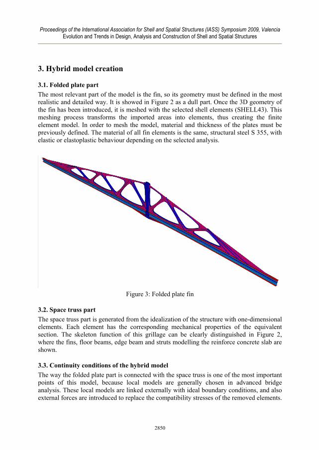
3.1. Folded plate part The most relevant part of the model is the fin, so its geometry must be defined in the most realistic and detailed way. It is showed in Figure 2 as a dull part. Once the 3D geometry of the fin has been introduced, it is meshed with the selected shell elements (SHELL43). This meshing process transforms the imported areas into elements, thus creating the finite element model. In order to mesh the model, material and thickness of the plates must be previously defined. The material of all fin elements is the same, structural steel S 355, with elastic or elastoplastic behaviour depending on the selected analysis.
Figure 3: Folded plate fin
3.2. Space truss part The space truss part is generated from the idealization of the structure with one-dimensional elements. Each element has the corresponding mechanical properties of the equivalent section. The skeleton function of this grillage can be clearly distinguished in Figure 2, where the fins, floor beams, edge beam and struts modelling the reinforce concrete slab are shown.
3.3. Continuity conditions of the hybrid model The way the folded plate part is connected with the space truss is one of the most important points of this model, because local models are generally chosen in advanced bridge analysis. These local models are linked externally with ideal boundary conditions, and also external forces are introduced to replace the compatibility stresses of the removed elements.
2850
Proceedings of the International Association for Shell and Spatial Structures (IASS) Symposium 2009, Valencia Evolution and Trends in Design, Analysis and Construction of Shell and Spatial Structures
Despite being common, this way of proceeding requires a previous modelling of the complete structure (with a space truss model for example) to obtain the external forces and the stiffness of the links. The result is finally ambiguous if a realistic, precise and reliable model is desired. Consequently, the idea of combining a folded plate model with a space truss emerges. In this hybrid model loads are applied in the usual way and boundary conditions only on piers and abutments. The grillage distributes the corresponding part of forces and displacements to each part of the structure. In order to guarantee a correct response of the whole model, it is necessary to connect the shell and beam elements through common nodes.
3.3.1. Fin web- upper fin cord connection In order to reduce the total number of shell elements, the upper fin cord is modelled with beam elements. It is possible to do so because this upper cord has a closed triangular compact section, which is distortion-free. These elements are directly connected to the upper nodes of the fin web shell mesh.
3.3.2. Fin web- transverse girder connection The lower fin cord is a I steel section, intersected each 2.5m by I section floor beams. Both webs must be rigidly connected in order to reproduce real constructive conditions. Lower fin cord web is modelled with shell elements, but transverse girders are beam elements, so the extreme node of the beam will be connected with the corresponding nodes of the fin web by constraints.
3.3.3. Fin web- lower fin cord in middle span connection In order to guarantee connection along the longitudinal resistant system in the middle span, where the fin modelled with shell elements ends, it is necessary to link the extreme node of the beam element to all the nodes that constitute the lower fin cord web. This must be a rigid connection, coherent with the plane deformation hypothesis of Navier’s Theory.
4. Basis of the analysis
4.1. Strategy The whole analysis is adapted to the specifications collected in the current standards (IAPF-07, RPM-95, EC-1, EC-3), concerning the magnitude of actions, their combination and the ultimate limit state (ULS) verifications. The hybrid model is especially useful for the instability ULS and tram impact verifications. Adapting the analysis to the current standards entails an inevitable simplification of it. The tram service load, for example, is not a real train but the one proposed by Eurocode-1, UIC 776-1 R, affected by a reduction coefficient α. This coefficient was obtained from a previous comparative analysis. Similarly, tram impact analysis against a structural element of the bridge is reduced to a strength verification of the element under a static equivalent force.
2851

Proceedings of the International Association for Shell and Spatial Structures (IASS) Symposium 2009, Valencia Evolution and Trends in Design, Analysis and Construction of Shell and Spatial Structures
4.2. Load combinations Following the idea of adapting the study to the current standards, the load combinations suggested will match the ULS proposed under the IAPF-07 standards. In the case of non linear geometric analysis, ULS combinations have to be adapted. To search of the critical load of the linearized buckling problem, ANSYSTM gives the solution in terms of a parameter λ, which means the proportion of variable load that causes the structure instability. Partial safety factor γQ is grouped with parameter λ, and finally the combination results as follows:
∑ ∑≥ >
⎟⎠
⎞⎜⎝
⎛ Ψ++1 1
,,01,,,i i
ikikikiG QQG λγ (1)
Non-linear buckling analysis is based on the step by step increase of the total load applied, as the deformed shape is updated. So in this case the load combination is:
⎟⎠
⎞⎜⎝
⎛ Ψ++⋅ ∑ ∑≥ >1 1
,,0,1,1,,,i i
ikiiQkQikiG QQG γγγλ (2)
4.3. Processed analysis
4.3.1. Non linear geometric analysis This analysis is divided in two parts. To approach the buckling phenomena, critical loads and shape modes are derived from the non-linear equilibrium equations, linearized in the perturbation. Were it an ideal structure, it would be possible to know the buckling safety factor of the structure from the critical load. But since it is a real structure, some load states could put its stability at risk, even without reaching the critical load. The previous linearized analysis does not take into account neither non-linear pre- and post-buckling behaviour nor initial imperfections of the real structure. It is well-known that plates and shells show a very different post-buckling response, which goes from an additional unexpected resistance to a sudden buckling before the critical load is reached. Therefore, in order to accurately predict the viaduct response, a P-δ analysis is carried out as follows. First, a fraction of the total load is applied and then increased until it reaches the critical load value. During this progressive load rise, displacements at some points of the structure are controlled, and graphically plotted. Buckling is observed when a sudden change in the slope of the load-displacement curve happens. This analysis lets us naturally add initial imperfections to the model, which are commonly introduced in the calculations as a scaled superposition of the first shape modes, derived from the initial buckling.
4.3.2. Elastoplastic analysis Due to yielding, the steel constitutive equation is actually non-linear. This fact is not usually considered in calculation models, because structures are designed and verified so
2852

Proceedings of the International Association for Shell and Spatial Structures (IASS) Symposium 2009, Valencia Evolution and Trends in Design, Analysis and Construction of Shell and Spatial Structures
that their behaviour is kept within the elastic range. With the purpose of guaranteeing the integrity of the structure in the case of tram impact against a structural element of the fins, an advanced elastoplastic analysis is run. The Spanish standard IAPF-07 makes it mandatory to consider this accidental event by means of the application of two punctual forces. In order to get realistic information about stress distribution, the yielded area and, if the ultimate strain is reached, the elastoplastic material must be considered in the model.
5. Application and results The following figures (4-13) are an example of the multiple results that the hybrid model, as a new and powerful analysis tool, offers to structural engineers. 5.1. Critical loads and buckling modes
Figure 4: First buckling mode shape for traffic load on lateral spans.
Figure 5: First buckling mode shape for traffic load on one lateral and central span.
5.2 Load-displacement analysis COMB1a
0
1000
2000
30004000
5000
6000
7000
8000
9000
10000
11000
12000
13000
14000
-0.025 0.005 0.035 0.065 0.095 0.125 0.155 0.185 0.215 0.245 0.275 0.305 0.335
d (m)
Fy (k
N)
Upper cord D2_a D2_b D2_c D1_a D1_b D1_c Ry
COMB1a with/without imperfection
01000
20003000
40005000
60007000
80009000
1000011000
12000130001400015000
0.000 0.025 0.050 0.075 0.100 0.125 0.150 0.175 0.200 0.225 0.250 0.275 0.300 0.325 0.350
d (m)
Fy (k
N)
Upper cord_imp 47mm Ry Upper cord_no imp Upper cord_imp 23.5mm
Figure 6: Controlled node displacement evolution. It shows the equilibrium path
of the structure.
Figure 7: Comparison between two controlled points with and without considering
imperfection
2853
Proceedings of the International Association for Shell and Spatial Structures (IASS) Symposium 2009, Valencia Evolution and Trends in Design, Analysis and Construction of Shell and Spatial Structures
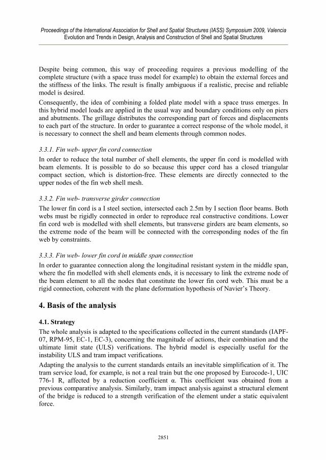
Figure 8: Deformed shape when instability occurs.
Figure 9: Stress distribution when instability occurs. Yielding limit is not exceeded.
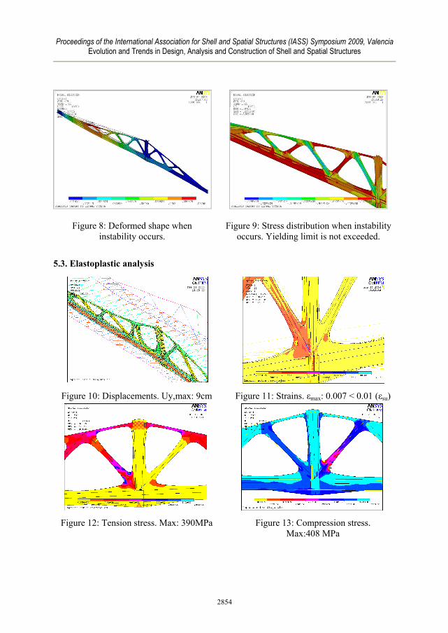
5.3. Elastoplastic analysis
Figure 10: Displacements. Uy,max: 9cm
Figure 11: Strains. εmax: 0.007 < 0.01 (εsu)
Figure 12: Tension stress. Max: 390MPa
Figure 13: Compression stress.
Max:408 MPa
2854

Proceedings of the International Association for Shell and Spatial Structures (IASS) Symposium 2009, Valencia Evolution and Trends in Design, Analysis and Construction of Shell and Spatial Structures
6. Conclusions The main conclusion about the use of hybrid models in the scope of civil structures is that they constitute a powerful design and checking tool at a reduced computational cost. This model can grasp physical phenomena such us web denting or post-buckling shell behaviour that are not considered with space truss models. Eigenvalue buckling checking is fast and matches the deformed shape at the moment it turns instable (analyzed with the geometric non linear process). Anyway, as the critical loads are obtained theoretically from a linearization of stability equations, information about the secondary equilibrium path is lost, and the results must be interpreted carefully. This fact is especially relevant with regards to shells, because their post-buckling response can vary from an additional unexpected resistance to a sudden buckling before the critical load is reached. The geometric non-linear analysis run lets us accurately know the whole equilibrium path of the controlled nodes, considering even initial imperfections. As we obtain load-displacement results and the ULS load level is known, it is easy to identify if the structure is near to an instability point. If yielding stress is surpassed, results of the geometric non-linear analysis must be read critically. In that case, stiffness of the affected sections is lower and the slope of the load-displacement curve is reduced, so the critical load could be minor. More complete calculations considering material non linearity, and of course geometric non linearity, would solve this uncertainty.
References [1] Argüelles Alvarez, R. et al., Estructuras de acero. Cálculo, Norma Básica y
Eurocódigo. Bellisco, 1999. [2] Brush, D.O and Almroth, B.O, Buckling of bars, plates, and shells. McGraw-Hill,
1975. [3] Eurocódigo 1: Acciones en estructuras. AENOR, 1996 [4] Eurocódigo 3: Proyecto de estructuras de acero. AENOR, 1996 [5] Instrucción de Acciones para Puentes de Ferrocarril (IAPF). MFOM, 2007 [6] Koiter, W.T., On the Stability of Elastic Equilibrium. Thesis, Delft, 1945. [7] Martinez Cutillas, A., Aplicación de los métodos generales de cálculo no lineal al
estudio de los puente mixtos, in: Martinez Calzón, J. Puentes Mixtos, estado actual de su tecnología y análisis. [Comunicaciones y Mesas Redondas de las III Jornadas Internacionales]. CICCP, Madrid, 2002.
[8] Monleón Cremades, S., Ingeniería de puentes, análisis estructural, SPUPV, 1997. [9] Zienkiewickz, O.C. and Taylor, R.L., El Método de los Elementos Finitos.
McGrawHill, 1994. [10] Recomendaciones para el proyecto de Puentes Metálicos (RPM). MFOM, 1995
2855