global frl air preparation system
TRANSCRIPT
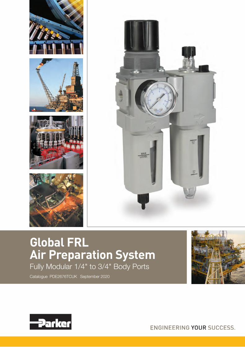
Global FRLAir Preparation SystemFully Modular 1/4" to 3/4" Body PortsCatalogue PDE2676TCUK September 2020

2
Parker Hannifin CorporationPneumatic Division - Europe
PDE2676TCUK
Parker Global Air Preparation System
WARNINGFAILURE OR IMPROPER SELECTION OR IMPROPER USE OF THE PRODUCTS AND/OR SYSTEMS DESCRIBED HEREIN OR RELATED ITEMS CAN CAUSE DEATH, PERSONAL INJURY AND PROPERTY DAMAGE.
This document and other information from Parker Hannifin Corporation, its subsidiaries and authorized distributors provide product and/or system options for further investigation by users having technical expertise. It is important that you analyze all aspects of your application including consequences of any failure, and review the information concerning the product or system in the current product catalog. Due to the variety of operating conditions and applications for these products or systems, the user, through its own analysis and testing, is solely responsible for making the final selection of the products and systems and assuring that all performance, safety and warning requirements of the application are met.
The products described herein, including without limitation, product features, specifications, designs, availability and pricing, are subject to change by Parker Hannifin Corporation and its subsidiaries at any time without notice.
Offer of SaleThe items described in this document are hereby offered for sale by Parker Hannifin Corporation, its subsidiaries or its authorized distributors. This offer and its acceptance are governed by the provisions stated on the separate page of this document entitled “Offer of Sale”.
© Copyright 2020, 2014, 2012, 2010 Parker Hannifin Corporation. All Rights Reserved
DECLARATION OF COMPLIANCE (ROHS)
European Directive 2011/65/EU – RoHS (Restriction us of certain Hazardous Substances in electrical and electronic equipment), restricts the use of the 6 substances in the manufacture of specified electrical equipment.
Lead: Product containing lead and its compound (except for applications of lead as an alloying element by weight in steel up to 0.35%, in aluminium up to 0.4% and in copper alloys up to 4% and in circuit board solder) must not exceed 0.1% by weight
Mercury: The concentration level must not exceed 0.1% by volume
Cadmium: The concentration level must not exceed 0.01% by volume
Hexavalent Chromiou:
This is a corrosive protective finish used on our product line. Where this finish is utilized the Chromate solution is Hexavalent (Chrome 6) free.
Polybrominated Biphenyls (PBB):
The concentration level must not exceed 0.1% by weight. This substance is not know to be in any of our products.
Polybrominated Diphenyl Esters (PBDE):
The concentration level must not exceed 0.1% by weight. This substance is not know to be in any of our products.
Following Ignition Hazard Assessments performed on the non-electrical Global Air Preparation products they are in accordance with the requirements of EN 13463-1:2009, it was considered that the equipment does not contain its own source of ignition, and therefore is not within the scope of directive 94/9/EC.
The products can be used in a Group II Category 2 environment assuming that the ATEX Directive and the following conditions are complied with:
• Installation and maintenance of the product must be undertaken by qualified personnel.
• Do not mount the products in an area where impact may occur.
• Filters must be used to limit the introduction of particles and to capture particles generated in service.
• Supply air quality must be within ISO 8573-1:2010 Class 6.4.4.
• Maximum working temperature to be as stated on product label.
• WARNING – pulsating pressure and/or a closed circuit can generate heat.
• Deposits of dust on the product must not exceed 5mm thickness. Refer to technical file for surface areas of plastics. The unit must be earthed via the compressed air supply line.
• The unit must not come into contact with liquid solvents, acids or alkalis Refer to technical file for chemicals known to be incompatible. Product cleaning must be undertaken using a method complying with the specifications of the ATEX zone, preferably by using mild soap and water or antistatic products.
• Regulators, Filter Regulators: Do not use Regulators or Filter Regulators within systems that can create vibration within the Regulator / Filter Regulator unit.
• Solenoid Operated Valves: Are suitable for use in an ATEX environment, (Group II Category 2) providing ATEX approved solenoids are fitted.
• Technical file available on request.
Global Air Preparation products supplied by Parker Hannifin have been designed and manufactured in accordance with “sound engineering practice”, as defined by Article 3 of Pressure Equipment Directive 97/23/EC.
Global Air Preparation product range has been designed and tested in accordance with ISO flow testing, envelope integrity, and catalog data presented.
• Filters – ISO 5782-1 & ISO 5782-2: 1997
• Regulators- ISO 6953-1 & ISO 6953-2: 2000
• Lubricators- ISO 6301-1 & ISO 6301-2: 2009
Global Air Preparation product range is in compliance with REACH to ensure continued compliance additions to the list of SVHC (Substance of Very High Concern) are reviewed periodically.
Global Air Preparation product range has been third party Shock & Vibration tested independently in accordance to EN 61373 : 1999, Category 2
COMPLIANT
ATEX

3
Parker Hannifin CorporationPneumatic Division - Europe
PDE2676TCUK
Parker Global Air Preparation System
Introduction ............................................................................................................................................................ 4-5
Together we can power your application with clean, dry air .................................................................................. 6-7
Specifying air quality in accordance with ISO8573-1:2010 .......................................................................................8
Application Guide .......................................................................................................................................................9
Comprehensive Offering Air Preparation ............................................................................................................ 10-11
Popular Combinations P31 Mini Series ..................................................................................................................................................12 P32 Compact Series ..........................................................................................................................................13 P33 Standard Series ..........................................................................................................................................14 Dimensions ........................................................................................................................................................15
Dust Filters P31 Mini Series ............................................................................................................................................ 16-17 P32 Compact Series .................................................................................................................................... 18-19 P33 Standard Series .................................................................................................................................... 20-21
Coalescing & Adsorber Filters P31 Mini Series ............................................................................................................................................ 22-23 P32 Compact Series .................................................................................................................................... 24-25 P33 Standard Series .................................................................................................................................... 26-27
Regulators P31 Mini Series ............................................................................................................................................ 28-29 P31 Mini Common Port Regulator Series .................................................................................................... 30-31 P32 Compact Series .................................................................................................................................... 32-33 P32 Compact Semi-Precision Regulator Series .......................................................................................... 34-35 P32 Compact Common Port Regulator Series ............................................................................................ 36-37 P33 Standard Series .................................................................................................................................... 38-39
Filter / Regulators P31 Mini Series ............................................................................................................................................ 40-41 P32 Compact Series .................................................................................................................................... 42-43 P32 Compact Semi-Precision Series ........................................................................................................... 44-45 P33 Standard Series .................................................................................................................................... 46-47Lubricators P31 Mini Series ............................................................................................................................................ 48-49 P32 Compact Series .................................................................................................................................... 50-51 P33 Standard Series .................................................................................................................................... 52-53
Proportional Regulators P31 Mini Series & P32/P33 Compact/Standard Series ............................................................................... 54-59
Dump Valve P31 Mini Series & P32/P33 Compact/Standard Series ............................................................................... 60-61
Soft Start Valve P31 Mini Series & P32/P33 Compact/Standard Series ............................................................................... 62-63
Combined Soft Start / Dump Valve P31 Mini Series & P32/P33 Compact/Standard .......................................................................................... 64-65
Solenoid Operators ............................................................................................................................................ 66-67
Dump, Combined Soft Start / Dump Valve Machine Directive - EN ISO 13849-1 ............................................. 68-71
Ball Valve / Lockout Valve ........................................................................................................................................72
Manifold and Branch Blocks ....................................................................................................................................73
Digital Pressure sensor .............................................................................................................................................74
Analog Pressure Sensors ................................................................................................................................... 75-76
Kits & Accessories P31 Mini Series ..................................................................................................................................................77 P32 Compact Series ..........................................................................................................................................78 P33 Standard Series ..........................................................................................................................................79
Safety Guide For Selecting And Using Pneumatic Division Products And Related Accessories ............................80

4
Parker Hannifin CorporationPneumatic Division - Europe
PDE2676TCUK
Parker Global Air Preparation System
Parker Global Air Preparation System
Global.Modular.Performance you need, wherever you need it.
Full featured particulate and coalescing filters, regulators, filter/regulators, and lubricators are available with a wide range of standard options to meet air preparation needs.
The comprehensive Global Air Preparation System is available in three body sizes with either BSPP or NPT to accommodate thread type requirements.
Individual units can easily be assembled into various combinations, utilizing patented modular lightweight body connectors.
Introduction

5
Parker Hannifin CorporationPneumatic Division - Europe
PDE2676TCUK
Parker Global Air Preparation System Introduction
A completely modular air preparation system
Easy to adjust non-rising knob with snap-lock, preventing accidental change of set pressure
Aluminumbody
NPT or BSPP porting available
2-piece Patented modular body connector US Patent number 5,383,689
Soft Start / Dump Valve
Coalescing Filter
Filter / Regulator
Ball Valve
Pressure gauge
Quick release bayonet-type integral bowl and bowl guard assembly
Padlock slide
Bowl guard with multiple viewing slots
Manual drain with pipe-away, auto drain available
• One facilitates the permanent tamperproofing of the Regulator and Filter/Regulator units
• Hinged black part clamps over control knob and is locked in place after sliding yellow cover over it
• Other allows for removable lockout/tagout tamperproofing - Four pad lock location holes tagout - Hinged locking clamp secures over existing knob via yellow cover which is slid over into place
• T-Handle (P32 only)
• Preset and Tamperproof
Additional Options (Consult factory for availability)
Optional Tamperproof Kits
• Preset
• Pressure Limiter

6
Parker Hannifin CorporationPneumatic Division - Europe
PDE2676TCUK
Parker Global Air Preparation System Introduction
Together we can power your application with clean, dry air
As air is compressedto 7 bar (100 psig)
and higher, the relative humidity quickly
reaches 100% RH and air temperatures can
reach between 110°C and 200°C (230°F and 392°F).
For every 11C (20F) that the air cools
after leaving the heat of the compressor,
50% of the moisture condenses into liquid
into the system.
The excess moisture condenses and
collects in the receiver tank and distribution
lines. This condensate must be removed.
Bulk liquid separators remove condensed
liquids after the aftercooler, receiver,
or anywhere within the distribution system.
Bulk liquid separators also help protect
downstream filters in the system where excess cooling takes
place.
Particulate filters are used for the removal
of solid particle contaminants down to
5 micron, as well as the removal of
condensed liquidsCoalescing filters are designed to remove
water and oil aerosols (not vapor) and
particulate from air streams down to 0.01
micron in size.
Note: Water and oil, in vapor form, pass
through general purpose particulate
filters.
This type of filter should be used as a prefilter for the coalescing (oil removal) filter.
Installed in pairs, Particulate and
Coalescing filters ensure a continuous supply of high quality
air.
Key
Particulate
Oil
Water
Oil Vapor
Water Vapor
1Stage 23
45
Fast cycle times, high product quality, and low downtime all require a clean, dry pneumatic system to function properly. Parker has what it takes to make sure pneumatic systems perform at their best.
Clean, dry pneumatic systems withParker Global Air Preparation

7
Parker Hannifin CorporationPneumatic Division - Europe
PDE2676TCUK
Parker Global Air Preparation System Introduction
Refrigeration, membrane and
desiccant dryers lower the air’s dew point by removing
water vapor, providing appropriately dry air for the downstream
application.
Hydrocarbon and oil vapors are removed using filters utilizing activated carbon.These airborne
hydrocarbons are often left over from the
compressor oils.
67
CleanDry Air
Stages
FunctionAir Compressor
Bulk Liquid Removal
Particulate Filtration
Coalescing Filtration
Air DryersHydrocarbon Removal
Application
All pneumatic systems
Basic pneumatic systems
Basic pneumatic systems
Systems requiring highest quality air.
Systems requiring air with reduced moisture content
Systems requiring highest quality air for critical applications
Description
Air leaving the compressor room at 93ºC (200ºF) releases 95% of its moisture into the piping system when it cools to 38ºC (100ºF)
Removes bulk liquid contamination and protects filters where excess cooling takes place in the distribution piping
Removes solid particulates down to 5 micron, and the separation of bulk contaminants.
Removes liquid aerosols and submicron particulates (not vapor) down to 0.01 micron.
Removes water vapor from air stream. Dew point reduced down to 4ºC (40ºF) (refrigeration) or -40ºC (-40ºF) (desiccant).
Removal of odors and trace vapors for critical applications.
Parker Global Air Preparation Solution
Customer supplied
P3TF Bulk Liquid Separator
P31, P32, P33 Particulate Filter
P31, P32, P33 Coalescing Filter
Refrigeration Dryer, TW Regenerative Desiccant Dryer
P31, P32, P33 Activated Carbon (Adsorber) Filter
431 2 5 76

8
Parker Hannifin CorporationPneumatic Division - Europe
PDE2676TCUK
Parker Global Air Preparation System Introduction
ISO8573-1:2010
CLASS
Solid Particulate Water Oil
Maximum number of particles per m3 Mass
Concentration
mg/m3
Vapour
Pressure
Dewpoint
Liquid
g/m3
Total Oil (aerosol liquid and vapour)
0,1 - 0,5 micron 0,5 - 1 micron 1 - 5 micron mg/m3
0 As specified by the equipment user or supplier and more stringent than Class 1
1 ≤ 20 000 ≤ 400 ≤ 10 - ≤ -70 °C - 0,01
2 ≤ 400 000 ≤ 6 000 ≤ 100 - ≤ -40 °C - 0,1
3 - ≤ 90 000 ≤ 1 000 - ≤ -20 °C - 1
4 - - ≤ 10 000 - ≤ +3 °C - 5
5 - - ≤ 100 000 - ≤ +7 °C - -
6 - - - ≤ 5 ≤ +10 °C - -
7 - - - 5 - 10 - ≤ 0,5 -
8 - - - - - 0,5 - 5 -
9 - - - - - 5 - 10 -
X - - - > 10 - > 10 > 10
Specifying air quality (purity) in accordance with ISO8573-1:2010, the international standard for compressed air quality
ISO8573-1 is the primary document used from the ISO8573 series as it is this document which specifies the amount of contamination allowed in each cubic metre of compressed air. ISO8573-1 lists the main contaminants as Solid Particulate, Water and Oil. The purity levels for each contaminant are shown separately in tabular form, however for ease of use, this document combines all three contaminants into one easy to use table.
Specifying air purity in accordance with ISO8573-1:2010When specifying the purity of air required, the standard must always be referenced, followed by the purity class selected for each contaminant (a different purity class can be selected for each contamination if required).An example of how to write an air quality specification is shown below:
ISO 8573-1:2010 Class 1.2.1ISO 8573-1:2010 refers to the standard document and its revision, the three digits refer to the purity classifications selected for solid particulate, water and total oil. Selecting an air purity class of 1.2.1 would specify the following air quality when operating at the standard’s reference conditions:
Class 1 - ParticulateIn each cubic metre of compressed air, the particulate count should not exceed 20,000 particles in the 0.1 - 0.5 micron size range, 400 particles in the 0.5 - 1 micron size range and 10 particles in the 1 - 5 micron size range.
Class 2 - WaterA pressure dewpoint (PDP) of -40°C or better is required and no liquid water is allowed.
Class 1 - OilIn each cubic metre of compressed air, not more than 0.01mg of oil is allowed. This is a total level for liquid oil, oil aerosol and oil vapour.
ISO8573-1:2010 Class zero • Class 0 does not mean zero contamination.• Class 0 requires the user and the equipment manufacturer to agree contamination levels as part of a written specification. • The agreed contamination levels for a Class 0 specification should be within the measurement capabilities of the test equipment and test methods shown in ISO8573 Pt 2 to Pt 9.• The agreed Class 0 specification must be written on all documentation to be in accordance with the standard.• Stating Class 0 without the agreed specification is meaningless and not in accordance with the standard.• A number of compressor manufacturers claim that the delivered air from their oil-free compressors is in compliance with Class 0.• If the compressor was tested in clean room conditions, the contamination detected at the outlet will be minimal. Should the same compressor now be installed in typical urban environment, the level of contamination will be dependent upon what is drawn into the compressor intake, rendering the Class 0 claim invalid. • A compressor delivering air to Class 0 will still require purification equipment in both the compressor room and at the point of use for the Class 0 purity to be maintained at the application.• Air for critical applications such as breathing, medical, food, etc typically only requires air quality to Class 2.2.1 or Class 2.1.1.• Purification of air to meet a Class 0 specification is only cost effective if carried out at the point of use.

9
Parker Hannifin CorporationPneumatic Division - Europe
PDE2676TCUK
Parker Global Air Preparation System Introduction
Application GuideFRL to Valve: The chart below contains recommendations for the correct selection of Global Air Preparation units to suit the number and size of valves in a typical application.
Actuator to FRL: The chart below contains recommendations for the correct selection of Global Air Preparation units suitable for each cylinder size. If you have a tube length over 2 m, choose one tube size larger than the chart. The table is based on a Maximum cylinder speed of 0.5m/s
P31 Mini Series P32 Compact Series P33 Standard Series
Number of valves that would actuate at once1 2 3 4 5 6 7 8 9 10 11 12 13 14 15 16
Moduflex 1
Isys Micro
HB / Viking Xtreme
Moduflex 2
HA / Global ISO
See Larger Parker FRL Offering
Cyl Ø mm Cyl Ø inches
Cylinder bore size
5(5/16)
10(7/16)
16(9/16)
20(3/4)
25(1)
28(1-1/8)
32(1-1/4)
40(1-1/2)
45(1-3/4)
50(2)
63(2-1/2)
75(3)
80(3-1/4)
100(4)
Tube Ø mm Tube Ø inches
Tube diameter external
4 (5/32)
4 (5/32)
4 (5/32)
6 (1/4)
6 (1/4)
6 (1/4)
6 (1/4)
8 (5/16)
8 (5/16)
8 (5/16)
10 (3/8)
10 (3/8)
12 (1/2)
12 (1/2)
1
2
3
4
5
6
7
8
9
10
P31 Mini Series P32 Compact Series P33 Standard Series P3Y Large Series
Num
ber
of
cylin
der
sac
tuat
ing
at
onc
e
Note: Data listed above is simply a guideline for a typical application only. Proper sizing and correct flow requirements must be taken into account.

10
Parker Hannifin CorporationPneumatic Division - Europe
PDE2676TCUK
Parker Global Air Preparation System Introduction
• 5µ particulate, 1.0µ and 0.01µ coalescing, and adsorber available as standard
• Transparent or metal bowl with manual or auto float drains standard
• Available as stand alone, common port and electronic proportional
• Both relieving and non-relieving versions available
• Compact design for space savings
• Available with all the same standard options as the filters and regulators
• Proportional oil delivery over a wide range of air flows
• Fill under pressure
• Compact design for space savings
• Easily assembled
• Many configurations available
• Solenoid operated soft start, quick dump, and soft start/quick dump valves
• Manifold blocks
• Ball style lockout / shutoff valve
• Repair kits, gauges, etc.
Filters
Lubricators Combinations Accessories
Regulators Filter / Regulators
P32 Compact Series1/4", 3/8" and 1/2"60mm body width
P31 Mini Series1/4" ports
40mm body width
P33 Standard Series1/2" and 3/4"
73mm body width
Comprehensive Offering

11
Parker Hannifin CorporationPneumatic Division - Europe
PDE2676TCUK
Parker Global Air Preparation System
P33 Standard Series
Air PreparationP31 Mini Series
P32 Compact Series
40mm body width1/4" Ported
Flows up to: dm3/s (scfm) Filter 12 (25) Coalescer 3,6 (7,5) Regulator 32 (68) Filter/Regulator 35 (74) Lubricator 25 (52)
Features: • Space saving integral gauge • Manifold style regulators available • OSHA compliant shut-off valves • Soft-Start & Quick Dump valves • Electronic Proportional Regulator
60mm body width1/4", 3/8", & 1/2" Ported
Flows up to: dm3/s (scfm) Filter 39 (82) Coalescer 17 (36) Regulator 78 (165) Filter/Regulator 77 (164) Lubricator 42 (90)
Features: • Manifold style regulators available • OSHA Compliant shut-off valves • Soft-Start & Quick Dump valves • Electronic Proportional Regulator
73mm body width1/2" & 3/4" Ported
Flows up to: dm3/s (scfm) Filter 48 (102) Coalescer 20 (42) Regulator 110 (233) Filter/Regulator 109 (235) Lubricator 71 (150)
Features: • OSHA Compliant shut-off valves • Soft-Start & Quick Dump valves (Utilizes P32 size only) • Electronic proportional regulator (Utilizes P32 size only)
Introduction

12
Parker Hannifin CorporationPneumatic Division - Europe
PDE2676TCUK
Parker Global Air Preparation System P31 Series
Flow with inlet pressure 10 bar (145 psig), Secondary pressure 6.3 bar (91.3 psig), 1 bar (14.5 psig) pressure drop.
Filter + Regulator + Lubricator Combinations, Poly bowl5 micron element, 8 bar (116 psig) regulator + gauge and wall mounting brackets
Port size Flow Manual drain Weight Pulse drain Weight
1/4" 13 dm3/s 27 (scfm) P31CB12GEMNTLNW 0.47 kg (1.04 lbs) P31CB12GEBNTLNW 0.47 kg (1.04 lbs)
Filter/Regulator + Lubricator Combinations, Poly bowl5 micron element, 8 bar (116 psig) regulator + gauge and wall mounting brackets
Port size Flow Manual drain Weight Pulse drain Weight
1/4" 14 dm3/s 28 (scfm) P31CA12GEMNTLNW 0.35 kg (0.77 lbs) P31CA12GEBNTLNW 0.35kg (0.77 lbs)
Ball Valve + Filter/Regulator + Lubricator Combinations, Poly bowl5 micron element, 8 bar (116 psig) regulator + gauge and wall mounting brackets
Port size Flow Manual drain Weight Pulse drain Weight
1/4" 14 dm3/s 28 (scfm) P31QA12GEMNTLNW 0.53 kg (1.17 lbs) P31QA12GEBNTLNW 0.53kg (1.17 lbs)
Ball Valve + Filter/Regulator Combinations + Poly bowl5 micron element, 8 bar Regulator + Gauge and Wall Mounting Brackets
Port size Flow Manual drain Weight Pulse drain Weight
1/4" 14 dm3/s 28 (scfm) P31QN12GEMNTW 0.37 kg (0.82 lbs) P31QN12GEBNTW 0.37 kg (0.82 lbs)
P 3 1
Thread type
BSPP 1
NPT 9
Port size
1/4 2
Bowl type
Poly bowl with bowl guard G
Metal bowl without sight glass M
Drain type
Manual drain M
Pulse drain B
Combination
Combination C
Shut off + Combination Q
Adjustment range
With square gauge
2 bar * V
4 bar S
8 bar ** T
Without gauge
2 bar Y
4 bar L
8 bar N
16 bar H
* Unit comes with 0-4 bar, gauge respectively** Unit comes with 0-10 bar, gauge respectively
Bar gauges fitted to BSPP
PSI gauges fitted to NPT
Combination type
F/R+L A
F+R+L B
F/R N
Note: All bowl types are the same for each component
Example: If a “G” is specified for a F+L, both units would get a poly bowl with bowl guard.
E2 N WL N
Add only for options
withLubricator
Port size Flow Manual drain Weight Pulse drain Weight
1/4" 13 dm3/s 27 (scfm) P31QB12GEMN5LNW 0.62 kg (1.37 lbs) P31QB12GEBN5LNW 0.62 kg (1.37 lbs)
Ball Valve + Filter + Regulator + Lubricator Combinations, poly bowl5 micron element, 8 bar (116 psig) regulator + gauge and wall mounting brackets
Options:
Popular Combinations:
Standard order code shown in bold.

13
Parker Hannifin CorporationPneumatic Division - Europe
PDE2676TCUK
Parker Global Air Preparation System
L N
Add only for options
withLubricator
P32 Series
Port size Flow Manual drain Weight Auto drain Weight
3/8" 33 dm3/s 70 (scfm) P32QA13GEMNGLNW 1.58 kg (3.48 lbs) P32QA13GEANGLNW 1.58 kg (3.48 lbs)
1/2" 43 dm3/s 90 (scfm) P32QA14GEMNGLNW 1.58 kg (3.48 lbs) P32QA14GEANGLNW 1.58 kg (3.48 lbs)
Ball Valve + Filter/Regulator + Lubricator Combinations, Poly bowl5 micron element, 8 bar (116 psig) regulator + gauge and wall mounting brackets
Port size Flow Manual drain Weight Auto drain Weight
1/4" 22 dm3/s 45 (scfm) P32CA12GEMNGLNW 1.03 kg (2.27 lbs) P32CA12GEANGLNW 1.03 kg (2.27 lbs)
3/8" 33 dm3/s 70 (scfm) P32CA13GEMNGLNW 1.03 kg (2.27 lbs) P32CA13GEANGLNW 1.03 kg (2.27 lbs)
1/2" 43 dm3/s 90 (scfm) P32CA14GEMNGLNW 1.03 kg (2.27 lbs) P32CA14GEANGLNW 1.03 kg (2.27 lbs)
Filter/Regulator + Lubricator Combinations, Poly bowl5 micron element, 8 bar (116 psig) regulator + gauge and wall mounting brackets
Port size Flow Manual drain Weight Auto drain Weight
1/4" 20 dm3/s 42 (scfm) P32CB12GEMNGLNW 1.38 kg (3.04 lbs) P32CB12GEANGLNW 1.38 kg (3.04 lbs)
3/8" 32 dm3/s 68 (scfm) P32CB13GEMNGLNW 1.38 kg (3.04 lbs) P32CB13GEANGLNW 1.38 kg (3.04 lbs)
1/2" 40 dm3/s 85 (scfm) P32CB14GEMNGLNW 1.38 kg (3.04 lbs) P32CB14GEANGLNW 1.38 kg (3.04 lbs)
Filter + Regulator + Lubricator Combinations, Poly bowl5 micron element, 8 bar (116 psig) regulator + gauge and wall mounting brackets
Thread type
BSPP 1
NPT 9
Port size
1/4 2
3/8 3
1/2 4
Bowl type
Poly bowl with bowl guard G
Metal bowl with sight glass S
Drain type
Auto drain A
Manual drain M
Adjustment range
With round gauge
2 bar; 0-30 psi; 0.2 MPa Z
4 bar; 60 psi; 0.4 MPa M
8 bar; 125 psi; 0.8 MPa G
Without gauge
2 bar Y
4 bar L
8 bar N
17 bar H
Combination type
F/R+L A
F+R+L B
F/R N
Note: All bowl types are the same for each component
Example: If a “G” is specified for a F+L, both units would get a poly bowl with bowl guard.
E N WP 3 2
Combination
Combination C
Shut off + Combination 1 Q
1 Option not available with F+R+L and 1/4" port size
Port size Flow Manual drain Weight Auto drain Weight
3/8" 33 dm3/s 70 (scfm) P32QN13GEMNGW 1.08 kg (2.38 lbs) P32QN13GEANGW 1.08 kg (2.38 lbs)
1/2" 43 dm3/s 90 (scfm) P32QN14GEMNGW 1.08 kg (2.38 lbs) P32QN14GEANGW 1.08 kg (2.38 lbs)
Ball Valve + Filter/Regulator Combinations + Poly bowl5 micron element, 8 bar Regulator + Gauge and Wall Mounting Brackets
Ball Valve + Filter + Regulator + Lubricator Combinations, poly bowl5 micron element, 116 psig (8 bar) regulator + gauge and wall mounting brackets
Port size Flow Manual drain Weight Auto drain Weight
1/4" 20 dm3/s 42 (scfm) P32QB12GEMNGLNW 1.74 kg (3.84 lbs) P32QB12GEANGLNW 1.74 kg (3.84 lbs)
3/8" 32 dm3/s 68 (scfm) P32QB93GEMNGLNW 1.74 kg (3.84 lbs) P32QB93GEANGLNW 1.74 kg (3.84 lbs)
1/2" 40 dm3/s 85 (scfm) P32QB94GEMNGLNW 1.74 kg (3.84 lbs) P32QB94GEANGLNW 1.74 kg (3.84 lbs)
* Unit comes with 0-4 bar, gauge respectively** Unit comes with 0-10 bar, gauge respectively
Bar gauges fitted to BSPP
PSI gauges fitted to NPT
Options:
Flow with inlet pressure 10 bar (145 psig), Secondary pressure 6.3 bar (91.3 psig), 1 bar (14.5 psig) pressure drop.
Popular Combinations:
Standard order code shown in bold.

14
Parker Hannifin CorporationPneumatic Division - Europe
PDE2676TCUK
Parker Global Air Preparation System
L N
Add only for options
withLubricator
Filter/Regulator + Lubricator Combinations, Poly bowl5 micron element, 8 bar (116 psig) regulator + gauge and wall mounting brackets
Ball Valve + Filter/Regulator + Lubricator Combinations, Poly bowl5 micron element, 8 bar (116 psig) regulator + gauge and wall mounting brackets
Port size Flow Manual drain Weight Auto drain Weight
1/2" 43 dm3/s 90 (scfm) P33CB14GEMNGLNW 1.93 kg (4.25 lbs) P33CB14GEANGLNW 1.93 kg (4.25 lbs)
3/4" 52 dm3/s 110 (scfm) P33CB16GEMNGLNW 1.93 kg (4.25 lbs) P33CB16GEANGLNW 1.93 kg (4.25 lbs)
Port size Flow Manual drain Weight Auto drain Weight
1/2" 52 dm3/s 110 (scfm) P33CA14GEMNGLNW 1.51 kg (3.33 lbs) P33CA14GEANGLNW 1.51 kg (3.33 lbs)
3/4" 71 dm3/s 150 (scfm) P33CA16GEMNGLNW 1.51 kg (3.33 lbs) P33CA16GEANGLNW 1.51 kg (3.33 lbs)
Port size Flow Manual drain Weight Auto drain Weight
1/2" 52 dm3/s 110 (scfm) P33QA14GEMNGLNW 2.25 kg (4.96 lbs) P33QA14GEANGLNW 2.25 kg (4.96 lbs)
3/4" 71 dm3/s 150 (scfm) P33QA16GEMNGLNW 2.25 kg (4.96 lbs) P33QA16GEANGLNW 2.25 kg (4.96 lbs)
Filter + Regulator + Lubricator Combinations, Poly bowl5 micron element, 8 bar (116 psig) regulator + gauge and wall mounting brackets
P 3 3
Thread type
BSPP 1
NPT 9
Port size
1/2 4
3/4 6
Bowl type
Poly bowl with bowl guard G
Metal bowl with sight glass S
Drain type
Auto drain A
Manual drain M
Adjustment range
With round gauge
2 bar; 0-30 psi; 0.2 MPa Z
4 bar; 60 psi; 0.4 MPa M
8 bar; 125 psi; 0.8 MPa G
Combination type
F/R+L A
F+R+L B
F/R N
Note: All bowl types are the same for each component
Example: If a “G” is specified for a F+L, both units would get a poly bowl with bowl guard.
E N W
Combination
Combination C
Shut off + Combination Q
Ball Valve + Filter/Regulator Combinations + Poly bowl5 micron element, 8 bar Regulator + Gauge and Wall Mounting Brackets
Port size Flow Manual drain Weight Auto drain Weight
1/2" 52 dm3/s 110 (scfm) P33QN14GEMNGW 1.59 kg (3.51 lbs) P33QN14GEANGW 1.59 kg (3.51 lbs)
3/4" 71 dm3/s 150 (scfm) P33QN16GEMNGW 1.59 kg (3.51 lbs) P33QN16GEANGW 1.59 kg (3.51 lbs)
P33 Series
Options:
Without gauge
2 bar Y
4 bar L
8 bar N
17 bar H
Flow with inlet pressure 10 bar (145 psig), Secondary pressure 6.3 bar (91.3 psig), 1 bar (14.5 psig) pressure drop.
Popular Combinations:
Standard order code shown in bold.

15
Parker Hannifin CorporationPneumatic Division - Europe
PDE2676TCUK
Parker Global Air Preparation System
Popular Combination Dimensions: mm (inches)
P31C
P32C
P33C
4mm (5/32")I.D. TubeBarb Fitting
35(1.38)
35(1.38)
120(4.72)40
(1.57)
39.7(1.56)40
(1.57)
159.7(6.29)
33(1.30)
BowlRemovalClearance
81(3.19)
SquareGauge
96(3.78)
RoundGauge
47.1(1.85)
100(3.94)
58(2.28)
50(1.97)
129(5.08)
64.5(2.54)
98.1(3.86)
SquareGauge
110.1(4.33)
RoundGauge
261.6(10.30)
4mm (5/32")I.D. TubeBarb Fitting Bowl
RemovalClearance
198(7.80)
69(2.72)
64.5(2.54)
100(3.94)
50(1.97)
BowlRemovalClearance
58(2.28)
229.3(9.03)
4mm (5/32")I.D. TubeBarb Fitting
47.1(1.85)
98.1(3.86)
SquareGauge
110.1(4.33)
RoundGauge
77.5(3.05)
155(6.10)
120(4.72)
47.1(1.85)
100(3.94)
50(1.97)
4.8mm (.19")I.D. TubeBarb Fitting
291(11.44)
51mm (2.00")Bowl Removal Clearance
82(3.23)
77.5(3.05)
237(9.33)
238(9.37)
100(3.94)
50(1.97)
4.8mm (.19")I.D. TubeBarb Fitting
120(4.72)
47.1(1.85)
51mm (2.00")Bowl Removal Clearance
4mm (5/32")I.D. TubeBarb Fitting
BowlRemovalClearance
40(1.57)
33.3(1.31)
35(1.38)
35(1.38)
176.9(6.96)
80(3.15)
39.7(1.56)
81(3.19)
SquareGauge
96(3.78)
RoundGauge
P31, P32, P33 Series

16
Parker Hannifin CorporationPneumatic Division - Europe
PDE2676TCUK
Parker Global Air Preparation System
Mini Particulate Filter - P31 Symbols
• Integral 1/4" ports (NPT & BSPP)
• High efficiency 5 micron element as standard
• Excellent water removal efficiency
• Robust but lightweight aluminum construction
• One hand operation for easy element cartridge removal
• Positive bayonet latch to ensure correct & safe fitting
1 221
Manual drain Pulse drain
Port size Description Flow ‡dm3/s (scfm)
Max.bar (psig)
Heightmm (inches)
Widthmm (inches)
Depthmm (inches) Part number ◊
1/4" Poly bowl - manual drain 12 (25) 10 (150) 124.8 (4.91) 40 (1.58) 40 (1.58) P31FB12EGMN
1/4" Poly bowl - pulse drain 12 (25) 10 (150) 119.6 (4.71) 40 (1.58) 40 (1.58) P31FB12EGBN
1/4" Metal bowl - manual drain 12 (25) 17 (250) 124.8 (4.91) 40 (1.58) 40 (1.58) P31FB12EMMN
1/4" Metal bowl - pulse drain 12 (25) 17 (250) 119.6 (4.71) 40 (1.58) 40 (1.58) P31FB12EMBN
‡ Flow with 6.3 bar (91.3 psig) inlet pressure and 0.34 (4.9 psig) pressure drop.◊ For thread type: BSPP 1 NPT 9
P31 Series
Order Code for Ordering

17
Parker Hannifin CorporationPneumatic Division - Europe
PDE2676TCUK
Parker Global Air Preparation System
Specifications
Flow capacity * 1/4 12 dm3/s (25 scfm)
Operating Plastic bowl -10°C to 52°C (14°F to 125°F) temperature Metal bowl -10°C to 65.5°C (14°F to 150°F)
Max. supply Plastic bowl 10 bar (150 psig) pressure Metal bowl 17 bar (250 psig)
Standard filtration 5 micron
Useful retention † 12 cm3 (0.4 US oz.)
Port size BSPP / NPT 1/4
Weight 0.11 kg (0.24 lbs)
* Inlet pressure 6.3 bar (91.3 psig). Pressure drop 0.34 bar (4.9 psig). † Useful retention refers to volume below the quiet zone baffle.
Air quality: Within ISO 8573-1: 1991 Class 3 (Particulates) Within ISO 8573-1: 2010 Class 6 (Particulates)
Material Specifications
Body Aluminum
Body cap ABS
Bowl Polycarbonate
Bowl guard Nylon
Element retainer Acetal
Baffle Acetal
Filter element Sintered polyethylene
Seals Nitrile
Dimensions mm (inches)
Flow Charts
Repair and Mounting Kits
Plastic bowl / Bowl guard manual drain P31KB00BGM
Metal bowl / w/o sight gauge manual drain P31KB00BMM
Plastic bowl / Bowl guard pulse drain P31KB00BGB
Metal bowl / w/o sight gauge pulse drain P31KB00BMB
5µ particle filter element P31KA00ESE †
C-bracket (fits to body) P31KA00MW †
T-bracket with body connector P31KA00MT †
Body connector P31KA00CB †
† Standard order code shown in bold.
1/4 Filter
Manual Drain Pulse Drain
Pre
ssur
e D
rop
- (b
ar)
Pre
ssur
e D
rop
- (p
sig)
0
2
4
6
5
3
1
7
00
0
5 10 15 302520Flow - (dm3/s) n
Flow - (scfm)10 20 40 50 6030
0.1
0.2
0.3
0.4
0.5
1.623.2
Primary Pressure - barPrimary Pressure - psig
4.058
6.391.4
10145
P31 Series
73.5(2.89)
176.9(6.96)
172.0(6.77)
40(1.58)
40(1.58)
20(.79)
33(1.30)
4mm (5/32)I.D. tubebarb �tting
Bowlremovalclearance
61.3(2.41)
SquareGauge
74.3(2.93)
RoundGauge

18
Parker Hannifin CorporationPneumatic Division - Europe
PDE2676TCUK
Parker Global Air Preparation System
Order Code for Ordering
Compact Particulate Filter - P32 Symbols
Port size Description Flow ‡
dm3/s (scfm)Max.bar (psig)
Heightmm (inches)
Widthmm (inches)
Depthmm (inches) Part number ◊
1/4" Poly bowl - manual drain 24 (50) 10 (150) 190.3 (7.49) 60 (2.36) 60 (2.36) P32FB12EGMN
1/4" Poly bowl - auto drain 24 (50) 10 (150) 184.3 (7.26) 60 (2.36) 60 (2.36) P32FB12EGAN
1/4" Metal bowl - manual drain 24 (50) 17 (250) 190.3 (7.49) 60 (2.36) 60 (2.36) P32FB12ESMN
1/4" Metal bowl - auto drain 24 (50) 17 (250) 184.3 (7.26) 60 (2.36) 60 (2.36) P32FB12ESAN
3/8" Poly bowl - manual drain 37 (78) 10 (150) 190.3 (7.49) 60 (2.36) 60 (2.36) P32FB13EGMN
3/8" Poly bowl - auto drain 37 (78) 10 (150) 184.3 (7.26) 60 (2.36) 60 (2.36) P32FB13EGAN
3/8" Metal bowl - manual drain 37 (78) 17 (250) 190.3 (7.49) 60 (2.36) 60 (2.36) P32FB13ESMN
3/8" Metal bowl - auto drain 37 (78) 17 (250) 184.3 (7.26) 60 (2.36) 60 (2.36) P32FB13ESAN
1/2" Poly bowl - manual drain 39 (82) 10 (150) 190.3 (7.49) 60 (2.36) 60 (2.36) P32FB14EGMN
1/2" Poly bowl - auto drain 39 (82) 10 (150) 184.3 (7.26) 60 (2.36) 60 (2.36) P32FB14EGAN
1/2" Metal bowl - manual drain 39 (82) 17 (250) 190.3 (7.49) 60 (2.36) 60 (2.36) P32FB14ESMN
1/2" Metal bowl - auto drain 39 (82) 17 (250) 184.3 (7.26) 60 (2.36) 60 (2.36) P32FB14ESAN
• Integral 1/4", 3/8" or 1/2" ports (NPT & BSPP)
• High efficiency 5 micron element as standard
• Excellent water removal efficiency
• Robust but lightweight aluminum construction
• Positive bayonet latch to ensure correct & safe fitting
‡ Flow with 6.3 bar (91.3 psig) inlet pressure and 0.34 (4.9 psig) pressure drop.◊ For thread type: BSPP 1 NPT 9
1 221
Manual drain Auto drain
P32 Series

19
Parker Hannifin CorporationPneumatic Division - Europe
PDE2676TCUK
Parker Global Air Preparation System
Flow ChartsSpecifications
Flow capacity * 1/4 24 dm3/s (50 scfm) 3/8 37 dm3/s (78 scfm) 1/2 39 dm3/s (82 scfm)
Operating Plastic bowl -25°C to 52°C (-13°F to 125°F) temperature Metal bowl -25°C to 65.5°C (-13°F to 150°F)
Max. supply Plastic bowl 10 bar (150 psig) pressure Metal bowl 17 bar (250 psig)
Standard filtration 5 micron
Useful retention † 51 cm3 (1.7 US oz.)
Port size BSPP / NPT 1/4, 3/8, 1/2
Weight 0.28 kg (0.62 lbs)
* Inlet pressure 6.3 bar (91.3 psig). Pressure drop 0.34 bar (4.9 psig). † Useful retention refers to volume below the quiet zone baffle.
Air quality: Within ISO 8573-1: 1991 Class 3 (Particulates) Within ISO 8573-1: 2010 Class 6 (Particulates)
Material Specifications
Body Aluminum
Body cap ABS
Bowls Plastic bowl Polycarbonate Metal bowl Aluminum
Bowl guard Nylon
Deflector Polypropylene
Element retainer / Baffle Acetal
Filter element Sintered polyethylene
Seals Nitrile
Sight gauge Metal bowl Nylon
Repair and Mounting Kits
Plastic bowl / Bowl guard manual drain P32KB00BGM
Metal bowl / Sight gauge manual drain P32KB00BSM
Auto drain P32KA00DA
5µ particle filter element P32KA00ESE †
L-bracket (fits to body) P32KA00ML †
T-bracket (fits to body connector) P32KA00MB †
T-bracket with body connector P32KA00MT †
Body connector P32KA00CB †
† Standard order code shown in bold.
P32FB 1/4" Filter
Pre
ssur
e D
rop
- (b
ar)
Pre
ssur
e D
rop
- (p
sig)
0
2
4
6
5
3
1
7
00
0
10 20 40305 15 3525
Flow - (scfm)20 40 8060
0.1
0.2
0.3
0.4
0.5
2.536.2
Primary Pressure - barPrimary Pressure - psig
6.391.4
10145
Flow - (dm3/s) n
P32FB 1/2" Filter
Pre
ssur
e D
rop
- (b
ar)
Pre
ssur
e D
rop
- (p
sig)
0
2
4
6
5
3
1
7
0
2.536.2
Primary Pressure - barPrimary Pressure - psig
6.391.4
10145
0
0
10 3020 40 60 807050
Flow - (scfm)20 40 60 80 100 120 140 160
0.1
0.2
0.3
0.4
0.5
Flow - (dm3/s) n
P32FB 3/8" FilterPrimary Pressure - barPrimary Pressure - psig
Pre
ssur
e D
rop
- (b
ar)
Pre
ssur
e D
rop
- (p
sig)
0
2
4
6
5
3
1
7
0
2.536.2
6.391.4
10145
0
0
10 3020 40 60 7050
Flow - (scfm)20 40 60 80 100 120 140
0.1
0.2
0.3
0.4
0.5
Flow - (dm3/s) n
P32 Series
Dimensions mm (inches)
Manual Drain Automatic Drain
60(2.36)
60(2.36)
26.3(1.04)
190.3(7.49)
184.3(7.26)
30(1.18)
58(2.28)
Bowlremovalclearance
4.8mm (.18)I.D. tubebarb �tting

20
Parker Hannifin CorporationPneumatic Division - Europe
PDE2676TCUK
Parker Global Air Preparation System
Order Code for Ordering
Standard Particulate Filter - P33 Symbols
Port size Description Flow ‡
dm3/s (scfm)Max.bar (psig)
Heightmm (inches)
Widthmm (inches)
Depthmm (inches) Part number ◊
1/2" Poly bowl - manual drain 40 (85) 10 (150) 213 (8.39) 73 (2.87) 73 (2.87) P33FA14EGMN
1/2" Poly bowl - auto drain 40 (85) 10 (150) 207 (8.15) 73 (2.87) 73 (2.87) P33FA14EGAN
1/2" Metal bowl - manual drain 40 (85) 17 (250) 213 (8.39) 73 (2.87) 73 (2.87) P33FA14ESMN
1/2" Metal bowl - auto drain 40 (85) 17 (250) 207 (8.15) 73 (2.87) 73 (2.87) P33FA14ESAN
3/4" Poly bowl - manual drain 48 (102) 10 (150) 213 (8.39) 73 (2.87) 73 (2.87) P33FA16EGMN
3/4" Poly bowl - auto drain 48 (102) 10 (150) 207 (8.15) 73 (2.87) 73 (2.87) P33FA16EGAN
3/4" Metal bowl - manual drain 48 (102) 17 (250) 213 (8.39) 73 (2.87) 73 (2.87) P33FA16ESMN
3/4" Metal bowl - auto drain 48 (102) 17 (250) 207 (8.15) 73 (2.87) 73 (2.87) P33FA16ESAN
• Integral 1/2" or 3/4" ports (NPT & BSPP)
• High efficiency 5 micron element as standard
• Excellent water removal efficiency
• Robust but lightweight aluminum construction
• Positive bayonet latch to ensure correct & safe fitting
‡ Flow with 6.3 bar (91.3 psig) inlet pressure and 0.34 (4.9 psig) pressure drop.◊ For thread type: BSPP 1 NPT 9
1 221
Manual drain Auto drain
P33 Series

21
Parker Hannifin CorporationPneumatic Division - Europe
PDE2676TCUK
Parker Global Air Preparation System
Pre
ssur
e D
rop
- (b
ar)
Pre
ssur
e D
rop
- (p
sig)
0
2
4
6
5
3
1
7
0
1.623.2
Primary Pressure - barPrimary Pressure - psig
4.058
6.391.4
10145
0
0
10 3020 40 60 7050
Flow - (scfm)20 40 60 80 100 120 140
0.1
0.2
0.3
0.4
0.5
Flow - (dm3/s) n
Pre
ssur
e D
rop
- (b
ar)
Pre
ssur
e D
rop
- (p
sig)
0
2
4
6
5
3
1
7
0
1.623.2
Primary Pressure - barPrimary Pressure - psig
4.058
6.391.4
10145
0
0
10 3020 40 60 807050
Flow - (scfm)20 40 60 80 100 120 140 160
0.1
0.2
0.3
0.4
0.5
Flow - (dm3/s) n
Flow ChartsSpecifications
Flow capacity * 1/2 40 dm3/s (85 scfm) 3/4 48 dm3/s (102 scfm)
Operating Plastic bowl -25°C to 52°C (-13°F to 125°F) temperature Metal bowl -25°C to 65.5°C (-13°F to 150°F)
Max. supply Plastic bowl 10 bar (150 psig) pressure Metal bowl 17 bar (250 psig)
Standard filtration 5 micron
Useful retention † 85 cm3 (2.8 US oz.)
Port size BSPP / NPT 1/2, 3/4
Weight 0.46 kg (1.01 lbs)* Inlet pressure 6.3 bar (91.3 psig). Pressure drop 0.34 bar (4.9 psig). † Useful retention refers to volume below the quiet zone baffle.
Air quality: Within ISO 8573-1: 1991 Class 3 (Particulates) Within ISO 8573-1: 2010 Class 6 (Particulates)
Material Specifications
Body Aluminum
Body cap ABS
Bowls Plastic bowl Polycarbonate Metal bowl Aluminum
Bowl guard Nylon
Deflector Polypropylene
Element retainer / Baffle Acetal
Filter element Sintered polyethylene
Seals Nitrile
Sight gauge Metal bowl Polycarbonate
Repair and Mounting Kits
Plastic bowl / Bowl guard manual drain P33KA00BGM
Metal bowl / Sight gauge manual drain P33KA00BSM
Auto drain P32KA00DA
5µ particle filter element P33KA00ESE †
L-bracket (fits to body) P33KA00ML †
T-bracket (fits to body connector) P32KA00MB †
T-bracket with body connector P33KA00MT †
Body connector P32KA00CB †
† Standard order code shown in bold.
3/4 Filter
1/2 Filter
Manual Drain Automatic Drain
Dimensions mm (inches)
P33 Series
73(2.87)
26(1.02)
73(2.87)
36(1.42)
213(8.39)
207(8.15)
Use 10mmor 3/8" FlexTubing51
(2.00)
4.8mm (.18)I.D. tubebarb �tting
Bowlremovalclearance

22
Parker Hannifin CorporationPneumatic Division - Europe
PDE2676TCUK
Parker Global Air Preparation System
Order Code for Ordering
Mini Coalescing and Adsorber Filters - P31
• Integral 1/4" ports (NPT & BSPP)
• Removes liquid aerosols and sub micron particles
• Oil free air for critical applications, such as air gauging, pneumatic instrumentation and control
• Differential Pressure Indicator (DPI) standard on Coalescing Filters
• Positive bayonet latch to ensure correct and safe fitting
• Adsorbing activated carbon element removes oil vapors and most hydrocarbons
Port size Description Flow ‡
dm3/s (scfm)Max.bar (psig)
Heightmm (inches)
Widthmm (inches)
Depthmm (inches) Part number ◊
1/4"Poly bowl - 0.01 micron - manual drain - with DPI
3.6 (7.5) 10 (150) 136.9 (5.39) 40 (1.58) 40 (1.58) P31FB12DGMN
1/4"Poly bowl - 0.01 micron - pulse drain - with DPI
3.6 (7.5) 10 (150) 131.7 (5.19) 40 (1.58) 40 (1.58) P31FB12DGBN
1/4"Metal bowl - 0.01 micron - manual drain - with DPI
3.6 (7.5) 10 (150) 136.9 (5.39) 40 (1.58) 40 (1.58) P31FB12DMMN
1/4"Metal bowl - 0.01 micron - pulse drain - with DPI
3.6 (7.5) 10 (150) 131.7 (5.19) 40 (1.58) 40 (1.58) P31FB12DMBN
1/4"Poly bowl - 1 micron - manual drain - with DPI
5.5 (12) 10 (150) 136.9 (5.39) 40 (1.58) 40 (1.58) P31FB12QGMN
1/4"Poly bowl - 1 micron - pulse drain - with DPI
5.5 (12) 10 (150) 131.7 (5.19) 40 (1.58) 40 (1.58) P31FB12QGBN
1/4"Metal bowl - 1 micron - manual drain - with DPI
5.5 (12) 10 (150) 136.9 (5.39) 40 (1.58) 40 (1.58) P31FB12QMMN
1/4"Metal bowl - 1 micron - pulse drain - with DPI
5.5 (12) 10 (150) 131.7 (5.19) 40 (1.58) 40 (1.58) P31FB12QMBN
1/4" Poly bowl - Adsorber - manual drain 6 (12.7) 10 (150) 136.9 (5.39) 40 (1.58) 40 (1.58) P31FB12AGMN
1/4" Metal bowl - Adsorber - manual drain 6 (12.7) 10 (150) 131.7 (5.19) 40 (1.58) 40 (1.58) P31FB12AMMN
Note: To optimize the life of coalescing element, it is advisable to install a P31F pre-filter with a 5 micron element upstream of the coalescing filter.
To optimize the life of an Adsorber it is advisable to install a P31 Coalescing Filter upstream of the Adsorber. Adsorber element should be replaced approximately every 1000 hours of service.
‡ Flow with 6.3 bar (91.3 psig) inlet pressure and 0.2 (3 psig) pressure drop.◊ For thread type: BSPP 1 NPT 9
Symbol
P31 Series

23
Parker Hannifin CorporationPneumatic Division - Europe
PDE2676TCUK
Parker Global Air Preparation System
Dimensions mm (inches)
Specifications
Flow capacity 1.0 micron coalescing 5.5 dm3/s (12 scfm) 0.01 micron coalescing 3.6 dm3/s (7.5 scfm) Activated carbon adsorber 6 dm3/s (12.7 scfm)
Operating Plastic bowl -10°C to 52°C (14°F to 125°F) temperature Metal bowl -10°C to 65.5°C (14°F to 150°F)
Max. supply Plastic bowl 10 bar (150 psig) pressure Metal bowl 10 bar (150 psig) §
Standard filtration 1.0 and 0.01 micron
Adsorber Max. oil carryover (ppm w/w) 0.003 @ 21°C (70°F)
Useful retention † 12 cm3 (0.4 US oz.)
Port size BSPP / NPT 1/4
Weight 0.11 kg (0.24 lbs)Inlet pressure 6.3 bar (91.3 psig), Pressure drop 0.2 bar (3 psig), Saturated Element.† Useful retention refers to volume below the quiet zone baffle.§ Without pressure indicator (DPI) – max. pressure for metal bowl version
is 17 bar (250 psig).
Material Specifications
Body Aluminum
Body cap ABS
Bowl Plastic bowl Polycarbonate Metal bowl Aluminum
Filter element 1.0 and .01 micron Borosilicate cloth
Adsorber Activated carbon
Seals Nitrile
Flow Charts
Repair and Mounting Kits
Plastic bowl / Bowl guard manual drain P31KB00BGM
Metal bowl / w/o sight gauge manual drain P31KB00BMM
Plastic bowl / Bowl guard pulse drain P31KB00BGB
Metal bowl / w/o sight gauge pulse drain P31KB00BMB
1µ coalescing filter element P31KA00ES9 †
0.01µ coalescing filter element P31KA00ESC †
Activated carbon adsorber filter element P31KA00ESA †
C-bracket (fits to body) P31KA00MW †
T-bracket with body connector P31KA00MT †
Body connector P31KA00CB †
Differential pressure indicator (replacement) P31KB00RQ† Standard order code shown in bold.
P31 - 1.0 micron flow
P31 - 0.01 micron flow
Manual Drain Pulse Drain
Pre
ssur
e D
rop
- (b
ar)
Pre
ssur
e D
rop
- (p
sig)
0
2
4
6
5
3
1
7
00
0
21 43 5
Flow - (scfm)5 10
0.1
0.2
0.3
0.4
0.5
1.623.2
Primary Pressure - barPrimary Pressure - psig
4.058
6.391.4
10145
Flow - (dm3/s) n
SaturatedElementFlow
SaturatedElementFlow
Pre
ssur
e D
rop
- (b
ar)
Pre
ssur
e D
rop
- (p
sig)
0
2
4
6
5
3
1
7
0
1.623.2
Primary Pressure - barPrimary Pressure - psig
4.058
6.391.4
10145
0
0
21 43 5 7 86
Flow - (scfm)5 10 15
0.1
0.2
0.3
0.4
0.5
Flow - (dm3/s) n
P31 Series
40(1.58)
20(.79)
40(1.58)
21.4(.84)
124.8(4.91)
33(1.30)
12.1(.48)
119.6(4.71)
12.1(.48)
4mm (5/32)I.D. tubebarb �tting
Bowlremovalclearance

24
Parker Hannifin CorporationPneumatic Division - Europe
PDE2676TCUK
Parker Global Air Preparation System
Order Code for Ordering
Port size Description Flow ‡
dm3/s (scfm)Max.bar (psig)
Heightmm (inches)
Widthmm (inches)
Depthmm (inches) Part number ◊
3/8"Poly bowl - 0.01 micron - manual drain - with DPI
17 (36) 10 (150) 212.3 (8.36) 60 (2.36) 60 (2.36) P32FB13DGMN
3/8"Poly bowl - 0.01 micron - auto drain - with DPI
17 (36) 10 (150) 206.3 (8.12) 60 (2.36) 60 (2.36) P32FB13DGAN
3/8"Metal bowl - 0.01 micron - manual drain - with DPI
17 (36) 17 (250) 212.3 (8.36) 60 (2.36) 60 (2.36) P32FB13DMMN
3/8"Metal bowl - 0.01 micron - auto drain - with DPI
17 (36) 17 (250) 206.3 (8.12) 60 (2.36) 60 (2.36) P32FB13DMAN
3/8"Poly bowl - 1 micron - manual drain - with DPI
25 (53) 10 (150) 212.3 (8.36) 60 (2.36) 60 (2.36) P32FB13QGMN
3/8"Poly bowl - 1 micron - auto drain - with DPI
25 (53) 10 (150) 206.3 (8.12) 60 (2.36) 60 (2.36) P32FB13QGAN
3/8"Metal bowl - 1 micron - manual drain - with DPI
25 (53) 17 (250) 212.3 (8.36) 60 (2.36) 60 (2.36) P32FB13QMMN
3/8"Metal bowl - 1 micron - auto drain - with DPI
25 (53) 17 (250) 206.3 (8.12) 60 (2.36) 60 (2.36) P32FB13QMAN
3/8" Poly bowl - Adsorber - manual drain 40 (85) 10 (150) 212.3 (8.36) 60 (2.36) 60 (2.36) P32FB13AGMN
3/8" Metal bowl - Adsorber - manual drain 40 (85) 17 (250) 206.3 (8.12) 60 (2.36) 60 (2.36) P32FB13AMMN
Compact Coalescing and Adsorber Filter - P32
• Integral 1/4", 3/8" or 1/2" ports (NPT & BSPP)• Removes liquid aerosols and sub micron particles• Oil free air for critical applications, such as air gauging,
pneumatic instrumentation and control• Differential Pressure Indicator (DPI) standard on
Coalescing Filters• Positive bayonet latch to ensure correct & safe fitting• Adsorbing activated carbon element removes oil
vapors and most hydrocarbons
‡ Flow with 6.3 bar (91.3 psig) inlet pressure and 0.2 (3 psig) pressure drop. ◊ For thread type: BSPP 1 NPT 9 Replace 3 with 2 for 1/4’’, 3 with 4 for 1/2’’ ports
Note: To optimize the life of coalescing element, it is advisable to install a P32F pre-filter with a 5 micron element upstream of the coalescing filter.
To optimize the life of an Adsorber it is advisable to install a P32 Coalescing Filter upstream of the Adsorber. Adsorber element should be replaced approximately every 1000 hours of service.
Symbol
P32 Series

25
Parker Hannifin CorporationPneumatic Division - Europe
PDE2676TCUK
Parker Global Air Preparation System
60(2.36)
60(2.36)
48.3(1.90)
212.3(8.36)
206.3(8.12)
30(1.18)
58(2.28)
4.8mm (.18)I.D. tubebarb �tting Bowl
removalclearance
Flow Charts
Material Specifications
Body Aluminum
Body cap ABS
Bowls Plastic bowl Polycarbonate Metal bowl Aluminum
Filter element 1.0 and .01 micron Borosilicate cloth
Adsorber Activated carbon
Seals Nitrile
Sight gauge Metal bowl Polycarbonate
Repair and Mounting KitsPlastic bowl / Bowl guard manual drain P32KB00BGM
Metal bowl / Sight gauge manual drain P32KB00BSM
Auto drain P32KA00DA
1µ coalescing filter element P32KA00ES9 †
0.01µ coalescing filter element P32KA00ESC †
Activated carbon adsorber filter element P32KA00ESA †
L-bracket (fits to body) P32KA00ML †
T-bracket (fits to body connector) P32KA00MB †
T-bracket with body connector P32KA00MT †
Body connector P32KA00CB †
Differential pressure indicator (replacement) P32KA00RQ† Standard order code shown in bold.
SaturatedElementFlow
Pre
ssur
e D
rop
- (b
ar)
Pre
ssur
e D
rop
- (p
sig)
0
2
4
6
5
3
1
7
0
2.536.3
Primary Pressure - barPrimary Pressure - psig
10145
6.391.4
0
0
2010 4030 50
Flow - (scfm)20 40 60 80 100
0.1
0.2
0.3
0.4
0.5
Flow - (dm3/s) n
P32 - 0.01 micron flow
Dimensions mm (inches)
Manual Drain Automatic Drain
Specifications
Flow capacity 1.0 micron coalescing 25 dm3/s (53 scfm) 0.01 micron coalescing 17 dm3/s (36 scfm) Activated carbon adsorber 40 dm3/s (85 scfm)
Operating Plastic bowl -25°C to 52°C (-13°F to 125°F) temperature Metal bowl -25°C to 65.5°C (-13°F to 150°F)
Max. supply Plastic bowl 10 bar (150 psig)
pressure Metal bowl 17 bar (250 psig) §
Standard filtration 1.0 and 0.01 micron
Adsorber Max. oil carryover (ppm w/w) 0.003 @ 21°C (70°F)
Useful retention † 51 cm3 (1.7 US oz.)
Port size BSPP / NPT 1/4, 3/8, 1/2
Weight 0.32 kg (0.71 lbs)Inlet pressure 6.3 bar (91.3 psig), Pressure drop 0.2 bar (3 psig), Saturated Element.† Useful retention refers to volume below the quiet zone baffle.§ Without pressure indicator (DPI) – max. pressure for metal bowl version
is 17 bar (250 psig).
P32 - 1.0 micron flow
SaturatedElementFlow
Pre
ssur
e D
rop
- (b
ar)
Pre
ssur
e D
rop
- (p
sig)
0
2
4
6
5
3
1
7
0
2.536.3
Primary Pressure - barPrimary Pressure - psig
6.391.4
10145
0
0
2010 40 6050 7030
Flow - (scfm)20 40 60 80 100 120 140
0.1
0.2
0.3
0.4
0.5
Flow - (dm3/s) n
P32 Series

26
Parker Hannifin CorporationPneumatic Division - Europe
PDE2676TCUK
Parker Global Air Preparation System
‡ Flow with 6.3 bar (91.3 psig) inlet pressure and 0.2 (3 psig) pressure drop. ◊ For thread type: BSPP 1 NPT 9 Replace 6 with 4 for 1/2" ports
Standard Coalescing and Adsorber Filter - P33
Port size Description Flow ‡
dm3/s (scfm)Max.bar (psig)
Heightmm (inches)
Widthmm (inches)
Depthmm (inches) Part number ◊
3/4"Poly bowl - 0.01 micron - manual drain - with DPI
20 (42) 10 (150) 235 (9.25) 73 (2.87) 73 (2.87) P33FA16DGMN
3/4"Poly bowl - 0.01 micron - auto drain - with DPI
20 (42) 10 (150) 229 (9.02) 73 (2.87) 73 (2.87) P33FA16DGAN
3/4"Metal bowl - 0.01 micron - manual drain - with DPI
20 (42) 17 (250) 235 (9.25) 73 (2.87) 73 (2.87) P33FA16DMMN
3/4"Metal bowl - 0.01 micron - auto drain - with DPI
20 (42) 17 (250) 229 (9.02) 73 (2.87) 73 (2.87) P33FA16DMAN
3/4"Poly bowl - 1 micron - manual drain - with DPI
32 (68) 10 (150) 235 (9.25) 73 (2.87) 73 (2.87) P33FA16QGMN
3/4"Poly bowl - 1 micron - auto drain - with DPI
32 (68) 10 (150) 229 (9.02) 73 (2.87) 73 (2.87) P33FA16QGAN
3/4"Metal bowl - 1 micron - manual drain - with DPI
32 (68) 17 (250) 235 (9.25) 73 (2.87) 73 (2.87) P33FA16QMMN
3/4"Metal bowl - 1 micron - auto drain - with DPI
32 (68) 17 (250) 229 (9.02) 73 (2.87) 73 (2.87) P33FA16QMAN
3/4" Poly bowl - Adsorber - manual drain 34 (72) 10 (150) 235 (9.25) 73 (2.87) 73 (2.87) P33FA16AGMN
3/4" Metal bowl - Adsorber - manual drain 34 (72) 17 (250) 229 (9.02) 73 (2.87) 73 (2.87) P33FA16AMMN
• Integral 1/2" or 3/4" ports (NPT & BSPP)• Removes liquid aerosols and sub micron particles• Oil free air for critical applications, such as air gauging,
pneumatic instrumentation and control• Differential Pressure Indicator (DPI) standard on
Coalescing Filters• Positive bayonet latch to ensure correct & safe fitting• Adsorbing activated carbon element removes oil
vapors and most hydrocarbons
Note: To optimize the life of coalescing element, it is advisable to install a P33F pre-filter with a 5 micron element upstream of the coalescing filter.
To optimize the life of an Adsorber it is advisable to install a P33 Coalescing Filter upstream of the Adsorber. Adsorber element should be replaced approximately every 1000 hours of service.
Symbol
P33 Series
Order Code for Ordering

27
Parker Hannifin CorporationPneumatic Division - Europe
PDE2676TCUK
Parker Global Air Preparation System
Flow Charts
Material Specifications
Body Aluminum
Body cap ABS
Bowls Plastic bowl Polycarbonate Metal bowl Aluminum
Filter element 1.0 and .01 micron Borosilicate cloth
Adsorber Activated carbon
Seals Nitrile
Sight gauge Metal bowl Polycarbonate
Repair and Mounting Kits
Plastic bowl / Bowl guard manual drain P33KA00BGM
Metal bowl / Sight gauge manual drain P33KA00BSM
Auto drain P32KA00DA
1µ coalescing filter element P33KA00ES9 †
0.01µ coalescing filter element P33KA00ESC †
Activated carbon adsorber filter element P33KA00ESA †
L-bracket (fits to body) P33KA00ML †
T-bracket (fits to body connector) P32KA00MB †
T-bracket with body connector P32KA00MT †
Body connector P32KA00CB †
Differential pressure indicator (replacement) P32KA00RQ† Standard order code shown in bold.
SaturatedElementFlow
Pre
ssur
e D
rop
- (b
ar)
Pre
ssur
e D
rop
- (p
sig)
0
2
4
6
5
3
1
7
0
2.029
Primary Pressure - barPrimary Pressure - psig
4.058
6.391.4
0.1
0.2
0.3
0.4
0.5
0
0
10 20 504030
Flow - (scfm)20 40 60 80 100
Flow - (dm3/s) n
SaturatedElementFlow
Pre
ssur
e D
rop
- (b
ar)
Pre
ssur
e D
rop
- (p
sig)
0
2
4
6
5
3
1
7
0
2.029
Primary Pressure - barPrimary Pressure - psig
4.058
6.391.4
0.1
0.2
0.3
0.4
0.5
Flow - (scfm)
0
0
10 20 4030
20 40 60 80
Flow - (dm3/s) n
P33 - 1.0 micron flow
P33 - 0.01 micron flow
Specifications
Flow capacity 1.0 micron coalescing 32 dm3/s (68 scfm) 0.01 micron coalescing 20 dm3/s (42 scfm) Activated carbon adsorber 34 dm3/s (72 scfm)
Operating Plastic bowl -25°C to 52°C (-13°F to 125°F) temperature Metal bowl -25°C to 65.5°C (-13°F to 150°F)
Max. supply Plastic bowl 10 bar (150 psig) pressure Metal bowl 17 bar (250 psig) §
Standard filtration 1.0 and 0.01 micron
Adsorber Max. oil carryover (ppm w/w) 0.003 @ 21°C (70°F)
Useful retention † 85 cm3 (2.8 US oz.)
Port size BSPP / NPT 1/2, 3/4
Weight 0.50 kg (1.10 lbs)
Inlet pressure 6.3 bar (91.3 psig), Pressure drop 0.2 bar (3 psig),
Saturated Element.† Useful retention refers to volume below the quiet zone baffle.§ Without pressure indicator (DPI) – max. pressure for metal bowl version
is 17 bar (250 psig).
P33 Series
Manual Drain Automatic Drain
Dimensions mm (inches)
73(2.87)
DPI
26(1.02)
73(2.87)
36(1.42)
235(9.25)
229(9.02)
4.8mm (.18)I.D. tubebarb �tting
Use 10mmor 3/8" FlexTubing51
(2.00)Bowl removalclearance

28
Parker Hannifin CorporationPneumatic Division - Europe
PDE2676TCUK
Parker Global Air Preparation System
CAUTION:REGULATOR PRESSURE ADJUSTMENT – The working range of knob adjustment is designed to permit outlet pressures within their full range. Pressure adjustment beyond this range is also possible because the knob is not a limiting device. This is a common characteristic of most industrial regulators, and limiting devices may be obtained only by special design. For best performance, regulated pressure should always be set by increasing the pressure up to the desired setting.
WARNINGProduct rupture can cause serious injury.Do not connect regulator to bottled gas.
Do not exceed Maximum primary pressure rating.
Mini Regulator - P31
• Integral 1/4" ports (NPT & BSPP)
• Robust but lightweight aluminum construction
• Secondary pressure ranges 0-2 bar (0-30 psig), 0-4 bar, (0-60 psig), 0-8 bar (0-125 psig), 0-16 bar (0-232 psig)
• Secondary aspiration plus balanced poppet provides quick response and accurate pressure regulation.
• Relieving & Non-relieving types
• Non-rising knob
P31 Series
Options:
Basic series
Global modular mini regulator P31RB
Thread typeBSPP 1NPT 9
MountingP Plastic panel mount nut
ReliefRelieving BNon-relieving NReverse flow / Relieving R
Port size1/4 2
Adjustment range With square gauge With round gauge
psig bar Z 2 bar; 30 psig; 0.2 MPa1 = 30 * V = 2 * M 4 bar; 60 psig; 0.4 MPa3 = 60 S = 4 G 8 bar; 125 psig; 0.8 MPa
5 = 125 T = 8 J 16 bar; 232 psig; 1.6 MPa
Without gaugeY 2 bar; 30 psig; 0.2 MPa
L 4 bar; 60 psig; 0.4 MPa
N 8 bar; 125 psig; 0.8 MPa
H 16 bar; 232 psig; 1.6 MPa
* Unit comes with 0-4 bar or 0-60 psig gauge respectively.
Bar gauges fitted to BSPPPSI gauges fitted to NPT
Symbols
Self relievingregulator with gauge
Non-relievingregulator
Reverse flowrelieving regulator
31 2
31 2
‡ Flow with 10 bar (145 psig) inlet pressure, 6.3 bar (91.3) psig) set pressure and 1 bar (14.5 psig) pressure drop.
Port size Description Flow ‡
dm3/s (scfm)Max.bar (psig)
Heightmm (inches)
Widthmm (inches)
Depthmm (inches) Part number
1/4" 8 bar (125 psig) relieving 32 (68) 20 (300) 104.1 (4.1) 40 (1.58) 40 (1.58) P31RB12BNNP
1/4" 8 bar (125 psig) + gauge 32 (68) 20 (300) 104.1 (4.1) 40 (1.58) 61.3 (2.41) P31RB12BNTP
Order Code for Ordering
P31RB 2 N P
Standard order code shown in bold.

29
Parker Hannifin CorporationPneumatic Division - Europe
PDE2676TCUK
Parker Global Air Preparation System
Repair and Mounting Kits
Diaphragm repair kit - relieving P31KB00RB
Diaphragm repair kit - non-relieving P31KB00RC
Panel mount nut - aluminum P31KA00MM
Panel mount nut - plastic P31KA00MP
Angle bracket (attaches via panel nut) P31KB00MR
C-bracket (fits to body) P31KA00MW
T-bracket with body connector P31KA00MT
Body connector P31KA00CB
NOTE: 30 mm (1.20 in.) hole required for panel nut mounting.
Specifications
Flow capacity * 1/4 32 dm3/s (68 scfm)
Operating temperature † -20°C to 65.5°C (-4°F to 150°F)
Max. supply pressure 20 bar (300 psig)
Adjusting range pressure 0-2 bar (30 psig) 0-4 bar (60 psig) 0-8 bar (125 psig) 0-16 bar (232 psig)
Port size BSPP / NPT 1/4
Gauge port (2 ea.) ** BSPP / NPT 1/8
Weight 0.17 kg (0.37 lbs)* Inlet pressure 10 bar (145 psig). Secondary pressure 6.3 bar (91.3 psig).
** Non-gauge option only.† Units with square gauges: -15°C to 65.5°C (5°F to 150°F)
Material Specifications
Body Aluminum
Adjustment knob Acetal
Bonnet PBT
Diaphragm assembly Brass / Nitrile
Valve assembly Brass / Nitrile
Springs Steel
Seals Nitrile
Panel nut Acetal
Flow Charts
Gauges
Square flush mount gauge
Square with adapter kit
0-4 bar K4511SCR04B
0-11 bar K4511SCR11B
0-60 psig K4511SCR060
0-160 psig K4511SCR160
0-4 bar P6G-PR11040
0-11 bar P6G-PR11110
0-60 psig P6G-PR90060
0-160 psig P6G-PR90160
1/4 Regulator
Inlet Pressure - 10 bar (145 psig)
Sec
onda
ry P
ress
ure
- (b
ar)
Sec
onda
ry P
ress
ure
- (p
sig)
0
20
40
60
80
100
120
140
2.5 bar36.3 psig
8.0 bar116 psig
4.0 bar58 psig
6.3 bar91.4 psig
0
2
3
4
5
6
7
8
9
10
1
0
0
105 15 25 3520 4030
Flow - (scfm)20 4010 30 60 8050 70
Flow - (dm3/s) n
40mm Round 1/8" center back mount
0-30 psig / 0-2 bar P3D-KAB1AYN
0-60 psig / 0-4 bar P3D-KAB1ALN
0-160 psig / 0-11 bar P3D-KAB1ANN
0-300 psig / 0-20 bar P3D-KAB1AHN
For best performance, regulated pressure should always be set by increasing the pressure up to the desired setting.
Dimensions mm (inches)
P31 Series
30.6(1.20)
56.8(2.24)
40(1.58)
40(1.58)
61.3(2.41)
20(.79)
SquareGauge
76.3(3.00)
RoundGauge
104.1(4.10)

30
Parker Hannifin CorporationPneumatic Division - Europe
PDE2676TCUK
Parker Global Air Preparation System
Symbols
Self relievingregulator with gauge
Non-relievingregulator
Reverse flowrelieving regulator
31 2
31 2
Mini Common - P1 Regulator - P31
• Manifold style regulator with line pressure on both sides
• Pressure output is at front or rear
• Inlet port 1/4" (NPT & BSPP)
• Working port 1/8"
• Robust construction
• Secondary pressure ranges 0-2 bar (0-30 psig), 0-4 bar, (0-60 psig), 0-8 bar (0-125 psig), 0-16 bar (0-232 psig)
• Secondary aspiration plus balanced poppet provides quick response and accurate pressure regulation
• Relieving & Non-relieving types
• Non-rising knob
P2
P2P2
P2
P1
P1
P1
P2 P2 P2 P2
P31 Series
Basic seriesGlobal modular mini common regulator
P31HB
Thread type
BSPP 1NPT 9
MountingP Plastic panel mount nut
Port size †
1/4 2
Adjustment range With square gauge Without gauge
psig bar Y 2 bar; 30 psig; 0.2 MPa1 = 30 * V = 2 * L 4 bar; 60 psig; 0.4 MPa3 = 60 S = 4 N 8 bar; 125 psig; 0.8 MPa
5 = 125 T = 8 H 16 bar; 232 psig; 1.6 MPa
* Unit comes with 0-4 bar or 0-60 psig gauge respectively.
† Working port 1/8".
ReliefRelieving BNon-relieving NReverse flow / Relieving R Bar gauges fitted to BSPP
PSI gauges fitted to NPT
Port size Description Flow ‡
dm3/s (scfm)Max.bar (psig)
Heightmm (inches)
Widthmm (inches)
Depthmm (inches) Part number
1/4" 8 bar (125 psig) relieving 20 (42) 20 (300) 104.1 (4.1) 40 (1.58) 40 (1.58) P31HB12BNNP
‡ Flow with 10 bar (145 psig) inlet pressure, 6.3 bar (91.3) psig) set pressure and 1 bar (14.5 psig) pressure drop.
Order Code for Ordering
P31HB 2 N P
CAUTION:REGULATOR PRESSURE ADJUSTMENT – The working range of knob adjustment is designed to permit outlet pressures within their full range. Pressure adjustment beyond this range is also possible because the knob is not a limiting device. This is a common characteristic of most industrial regulators, and limiting devices may be obtained only by special design. For best performance, regulated pressure should always be set by increasing the pressure up to the desired setting.
WARNINGProduct rupture can cause serious injury.Do not connect regulator to bottled gas.
Do not exceed Maximum primary pressure rating.
Standard order code shown in bold.
Options:

31
Parker Hannifin CorporationPneumatic Division - Europe
PDE2676TCUK
Parker Global Air Preparation System
NOTE: 30 mm (1.20 in.) hole required for panel nut mounting.
Specifications
Flow capacity * 1/4 20 dm3/s (42 scfm)
Operating temperature -20°C to 65.5°C (-4°F to 150°F)
Max. supply pressure 20 bar (300 psig)
Adjusting range pressure 0-2 bar (30 psig) 0-4 bar (60 psig) 0-8 bar (125 psig) 0-16 bar (232 psig)
P1 Port size (Inlet / Outlet) BSPP / NPT 1/4
P2 Regulated ports (2 ea.) BSPP / NPT 1/8
Weight 0.30 kg (0.66 lbs)* Inlet pressure 10 bar (145 psig). Secondary pressure 6.3 bar (91.3 psig).
Materials of Construction
Body Aluminum
Adjustment knob Acetal
Bonnet 33% Glass-filled PBT
Diaphragm assembly Brass / Nitrile
Valve assembly Brass / Nitrile
Flow Charts
1/4 Common Regulator
Dimensions mm (inches)
Inlet Pressure - 10 bar (145 psig)
Sec
onda
ry P
ress
ure
- (b
ar)
Sec
onda
ry P
ress
ure
- (p
sig)
0
20
40
60
80
100
120
140
2.5 bar36.3 psig
8.0 bar116 psig
4.0 bar58 psig
6.3 bar91.4 psig
0
2
3
4
5
6
7
8
9
10
1
0
0
105 15 25 3520 30
Flow - (scfm)20 4010 30 6050 70
Flow - (dm3/s) n
For best performance, regulated pressure should always be set by increasing the pressure up to the desired setting.
P31 Series
Repair and Mounting Kits
Diaphragm repair kit - relieving P31KB00RB
Diaphragm repair kit - non-relieving P31KB00RC
Panel mount nut - aluminum P31KA00MM
Panel mount nut - plastic P31KA00MP
Angle bracket (attaches via panel nut) P31KB00MR
T-bracket with body connector P31KA00MT
Body connector P31KA00CB
40mm Round 1/8" center back mount
0-30 psig / 0-2 bar P3D-KAB1AYN
0-60 psig / 0-4 bar P3D-KAB1ALN
0-160 psig / 0-11 bar P3D-KAB1ANN
0-300 psig / 0-20 bar P3D-KAB1AHN
Gauges
Square with adapter kit
0-4 bar P6G-PR11040
0-11 bar P6G-PR11110
0-60 psig P6G-PR90060
0-160 psig P6G-PR90160
104.1(4.10)
30.6(1.20)
56.8(2.24)
40(1.58)
40(1.58)
20(.79)

32
Parker Hannifin CorporationPneumatic Division - Europe
PDE2676TCUK
Parker Global Air Preparation System
Symbols
Self relievingregulator with gauge
Non-relievingregulator
Reverse flowrelieving regulator
31 2
31 2
Compact Regulator – P32
• Integral 1/4", 3/8" or 1/2" ports (NPT & BSPP)
• Robust but lightweight aluminum construction
• Secondary pressure ranges 0-2 bar (0-30 psig), 0-4 bar, (0-60 psig), 0-8 bar (0-125 psig), 0-17 bar (0-250 psig)
• Secondary aspiration plus balanced poppet provides quick response and accurate pressure regulation
• Relieving & Non-relieving types
• Non-rising knob
Adjustment rangeWith round gauge
Z 2 bar; 30 psig; 0.2 MPaM 4 bar; 60 psig; 0.4 MPaG 8 bar; 125 psig; 0.8 MPaJ 16 bar; 232 psig; 1.6 MPa
Without gaugeY 2 bar; 30 psig; 0.2 MPa
L 4 bar; 60 psig; 0.4 MPa
N 8 bar; 125 psig; 0.8 MPa
H 16 bar; 232 psig; 1.6 MPa
Basic seriesGlobal modular compact regulator
P32RB
Thread typeBSPP 1NPT 9
MountingP Plastic panel mount nut
ReliefRelieving BNon-relieving N
Port size1/4 23/8 31/2 4
Note: Regulators will reverse flow as standard.
P32 Series
‡ Flow with 10 bar (145 psig) inlet pressure, 6.3 bar (91.3) psig) set pressure and 1 bar (14.5 psig) pressure drop.
Port size Description Flow ‡
dm3/s (scfm)Max.bar (psig)
Heightmm (inches)
Widthmm (inches)
Depthmm (inches) Part number
1/4" 8 bar (125 psig) relieving 70 (148) 20 (300) 136 (5.4) 60 (2.36) 60 (2.36) P32RB12BNNP
1/4" 8 bar (125 psig) relieving + gauge 70 (148) 20 (300) 136 (5.4) 60 (2.36) 93 (3.66) P32RB12BNGP
3/8" 8 bar (125 psig) relieving 78 (165) 20 (300) 136 (5.4) 60 (2.36) 60 (2.36) P32RB13BNNP
3/8" 8 bar (125 psig) relieving + gauge 78 (165) 20 (300) 136 (5.4) 60 (2.36) 93 (3.66) P32RB13BNGP
1/2" 8 bar (125 psig) relieving 78 (165) 20 (300) 136 (5.4) 60 (2.36) 60 (2.36) P32RB14BNNP
1/2" 8 bar (125 psig) relieving + gauge 78 (165) 20 (300) 136 (5.4) 60 (2.36) 93 (3.66) P32RB14BNGP
Order Code for Ordering
P32RB N P
CAUTION:REGULATOR PRESSURE ADJUSTMENT – The working range of knob adjustment is designed to permit outlet pressures within their full range. Pressure adjustment beyond this range is also possible because the knob is not a limiting device. This is a common characteristic of most industrial regulators, and limiting devices may be obtained only by special design. For best performance, regulated pressure should always be set by increasing the pressure up to the desired setting.
WARNINGProduct rupture can cause serious injury.Do not connect regulator to bottled gas.
Do not exceed Maximum primary pressure rating.
Standard order code shown in bold.
Options:

33
Parker Hannifin CorporationPneumatic Division - Europe
PDE2676TCUK
Parker Global Air Preparation System
Inlet Pressure - 10 bar (145 psig)
Sec
onda
ry P
ress
ure
- (b
ar)
Sec
onda
ry P
ress
ure
- (p
sig)
0
20
40
60
80
100
120
140
2.5 bar36.3 psig
8.0 bar116 psig
4.0 bar58 psig
6.3 bar91.4 psig
0
2
3
4
5
6
7
8
9
10
1
0
0
10 3020 40 60 70 80 9050
Flow - (scfm)20 40 60 80 100 120 140 160 180
Flow - (dm3/s) n
Repair and Mounting Kits
Diaphragm repair kit - relieving P32KB00RB
Diaphragm repair kit - non-relieving P32KB00RC
Panel mount nut - aluminum P32KA00MM
Panel mount nut - plastic P32KA00MP
Angle bracket (attaches via panel nut) P32KB00MR
T-bracket with body connector P32KA00MT
T-bracket P32KA00MB
Body connector P32KA00CB
Flow ChartsSpecifications
Flow capacity * 1/4 70 dm3/s (148 scfm) 3/8 78 dm3/s (165 scfm) 1/2 78 dm3/s (165 scfm)
Operating temperature -25°C to 65.5°C (-13°F to 150°F)
Max. supply pressure 20 bar (300 psig)
Adjusting range pressure 0-2 bar (30 psig) 0-4 bar (60 psig) 0-8 bar (125 psig) 0-17 bar (250 psig)
Port size BSPP / NPT 1/4, 3/8, 1/2
Gauge port (2 ea.) BSPP / NPT 1/4
Weight 0.41 kg (0.90 lbs)* Inlet pressure 10 bar (145 psig). Secondary pressure 6.3 bar (91.3 psig).
Material Specifications
Body Aluminum
Adjustment knob Acetal
Bonnet 33% Glass-filled nylon
Diaphragm assembly Nitrile / Zinc
Valve assembly Brass / Nitrile
Spring, main regulating valve Steel, Stainless Steel
Seals Nitrile
Panel nut Acetal
3/8 Regulator
1/2 Regulator
1/4 Regulator
Inlet Pressure - 10 bar (145 psig)
Sec
onda
ry P
ress
ure
- (b
ar)
Sec
onda
ry P
ress
ure
- (p
sig)
0
20
40
60
80
100
120
140
2.5 bar36.3 psig
8.0 bar116 psig
4.0 bar58 psig
6.3 bar91.4 psig
0
2
3
4
5
6
7
8
9
10
1
0
0
10 3020 40 60 70 80 9050
Flow - (scfm)20 40 60 80 100 120 140 160 180
Flow - (dm3/s) n
P32 Series
0-60 psig / 0-4 bar P6G-ERB2040
0-160 psig / 0-11 bar P6G-ERB2110
0-300 psig / 0-20 bar P6G-ERB2200
Gauges
50mm (2") Round 1/4" center back mount
Square with adapter kit
0-4 bar P6G-PR11040
0-11 bar P6G-PR11110
0-60 psig P6G-PR90060
0-160 psig P6G-PR90160
For best performance, regulated pressure should always be set by increasing the pressure up to the desired setting.
NOTE: 48 mm (1.90 in.) hole required for panel nut mounting.
Dimensions mm (inches)
60(2.36)
136.1(5.36)
73.8(2.91)
60(2.36)
30(1.18)
81(3.19)
SquareGauge
93(3.66)
RoundGauge
38.5(1.52)

34
Parker Hannifin CorporationPneumatic Division - Europe
PDE2676TCUK
Parker Global Air Preparation System
Symbols
Self relievingregulator with gauge
Non-relievingregulator
Reverse flowrelieving regulator
31 2
31 2
Compact Semi-Precision Regulator – P32
• Integral 1/4", 3/8" or 1/2" ports (NPT & BSPP)
• Robust but lightweight aluminum construction
• Secondary pressure ranges 0-2 bar (0-30 psig), 0-4 bar, (0-60 psig), 0-8 bar (0-125 psig), 0-17 bar (0-250 psig)
• Secondary aspiration plus balanced poppet provides quick response and accurate pressure regulation
• Relieving & Non-relieving types
• Non-rising knob
Basic seriesGlobal modular compact regulator
P32RB
Thread typeBSPP 1NPT 9
MountingP Plastic panel mount nut
ReliefRelieving PNon-relieving E
Port size1/4 23/8 31/2 4
Adjustment range With round gauge
Z 2 bar; 30 psig; 0.2 MPaM 4 bar; 60 psig; 0.4 MPaG 8 bar; 125 psig; 0.8 MPaJ 17 bar; 250 psig; 1.7 MPa
Without gaugeY 2 bar; 30 psig; 0.2 MPa
L 4 bar; 60 psig; 0.4 MPa
N 8 bar; 125 psig; 0.8 MPa
H 17 bar; 250 psig; 1.7 MPaNote: Regulators will reverse
flow as standard.
P32 Series
† Standard part numbers shown in bold. For other models refer to Options chart above.‡ Flow with 10 bar (145 psig) inlet pressure, 6.3 bar (91.3) psig) set pressure and 1 bar (14.5 psig) pressure drop.
Port size Description Flow ‡
dm3/s (scfm)Max.bar (psig)
Heightmm (inches)
Widthmm (inches)
Depthmm (inches) Part number †
1/4" 8 bar (125 psig) relieving 25 (53) 20 (300) 136 (5.4) 60 (2.36) 60 (2.36) P32RB12PNNP
1/4" 8 bar (125 psig) relieving + gauge 25 (53) 20 (300) 136 (5.4) 60 (2.36) 93 (3.66) P32RB12PNGP
3/8" 8 bar (125 psig) relieving 25 (53) 20 (300) 136 (5.4) 60 (2.36) 60 (2.36) P32RB13PNNP
3/8" 8 bar (125 psig) relieving + gauge 25 (53) 20 (300) 136 (5.4) 60 (2.36) 93 (3.66) P32RB13PNGP
1/2" 8 bar (125 psig) relieving 25 (53) 20 (300) 136 (5.4) 60 (2.36) 60 (2.36) P32RB14PNNP
1/2" 8 bar (125 psig) relieving + gauge 25 (53) 20 (300) 136 (5.4) 60 (2.36) 93 (3.66) P32RB14PNGP
Order Code for Ordering
P32RB N P
CAUTION:REGULATOR PRESSURE ADJUSTMENT – The working range of knob adjustment is designed to permit outlet pressures within their full range. Pressure adjustment beyond this range is also possible because the knob is not a limiting device. This is a common characteristic of most industrial regulators, and limiting devices may be obtained only by special design. For best performance, regulated pressure should always be set by increasing the pressure up to the desired setting.
WARNINGProduct rupture can cause serious injury.Do not connect regulator to bottled gas.
Do not exceed Maximum primary pressure rating.
Standard order code shown in bold.
Options:

35
Parker Hannifin CorporationPneumatic Division - Europe
PDE2676TCUK
Parker Global Air Preparation System
Repair and Mounting Kits
Diaphragm repair kit - relieving P32KB00RB
Diaphragm repair kit - non-relieving P32KB00RC
Panel mount nut - aluminum P32KA00MM
Panel mount nut - plastic P32KA00MP
Angle bracket (attaches via panel nut) P32KB00MR
T-bracket with body connector P32KA00MT
T-bracket P32KA00MB
Body connector P32KA00CB
Flow ChartsSpecifications
Flow capacity * 1/4 25 dm3/s (53 scfm) 3/8 25 dm3/s (53 scfm) 1/2 25 dm3/s (53 scfm)
Effect of supply pressure variation 0.04 bar (0.6 PSIG) for 1.7 bar (25 PSIG) change in P1
Operating temperature -25°C to 65.5°C (-13°F to 150°F)
Max. supply pressure 20 bar (300 psig)
Adjusting range pressure 0-2 bar (30 psig) 0-4 bar (60 psig) 0-8 bar (125 psig) 0-17 bar (250 psig)
Port size BSPP / NPT 1/4, 3/8, 1/2
Gauge port (2 ea.) BSPP / NPT 1/4
Weight 0.41 kg (0.90 lbs)* Inlet pressure 10 bar (145 psig). Secondary pressure 6.3 bar (91.3 psig).
Material Specifications
Body Aluminum
Adjustment knob Acetal
Bonnet 33% Glass-filled nylon
Diaphragm assembly Nitrile / Zinc
Valve assembly Brass / Nitrile
Spring, main regulating valve Steel, Stainless Steel
Seals Nitrile
Panel nut Acetal
3/8 Regulator
1/2 Regulator
1/4 Regulator
Pre
ssur
e D
rop
- (b
ar)
Pre
ssur
e D
rop
- (p
sig)
0
40
80
120
100
60
20
140
0
2.5 bar36.3 psig
4.0 bar58 psig
6.3 bar91.4 psig
8.0 bar116 psig
Inlet Pressure - 10 bar (145 psig)
0
0
105 20 3025 3515
Flow - (scfm)10 20 30 40 50 60 70
2
4
6
8
1
3
5
7
910
Flow - (dm3/s) n
Pre
ssur
e D
rop
- (b
ar)
Pre
ssur
e D
rop
- (p
sig)
0
40
80
120
100
60
20
140
2.5 bar36.3 psig
4.0 bar58 psig
6.3 bar91.4 psig
8.0 bar116 psig
Inlet Pressure - 10 bar (145 psig)
0
0
105 20 3025 3515
Flow - (scfm)10 20 30 40 50 60 70
0
2
4
6
8
1
3
5
7
910
Flow - (dm3/s) n
Pre
ssur
e D
rop
- (b
ar)
Pre
ssur
e D
rop
- (p
sig)
0
40
80
120
100
60
20
140
2.5 bar36.3 psig
4.0 bar58 psig
6.3 bar91.4 psig
8.0 bar116 psig
Inlet Pressure - 10 bar (145 psig)
0
0
105 20 3025 3515
Flow - (scfm)10 20 30 40 50 60 70
0
2
4
6
8
1
3
5
7
910
Flow - (dm3/s) n
P32 Series
0-60 psig / 0-4 bar P6G-ERB2040
0-160 psig / 0-11 bar P6G-ERB2110
0-300 psig / 0-20 bar P6G-ERB2200
Gauges
50mm (2") Round 1/4" center back mount
For best performance, regulated pressure should always be set by increasing the pressure up to the desired setting.
NOTE: 48 mm (1.90 in.) hole required for panel nut mounting.
Dimensions mm (inches)
60(2.36)
136.1(5.36)
73.8(2.91)
60(2.36)
30(1.18)
81(3.19)
SquareGauge
93(3.66)
RoundGauge
38.5(1.52)

36
Parker Hannifin CorporationPneumatic Division - Europe
PDE2676TCUK
Parker Global Air Preparation System
Symbols
Self relievingregulator with gauge
Non-relievingregulator
Reverse flowrelieving regulator
31 2
31 2
Compact Common - P1 Regulator - P32
P2
P1
P1
P1
P2 P2 P2 P2
Basic seriesGlobal modular compact regulator
P32HB
Thread typeBSPP 1NPT 9
MountingP Plastic panel mount nut
ReliefRelieving BNon-relieving N
Adjustment rangeWith round gauge
Z 2 bar; 30 psig; 0.2 MPaM 4 bar; 60 psig; 0.4 MPaG 8 bar; 125 psig; 0.8 MPaJ 17 bar; 250 psig; 1.7 MPa
Without gaugeY 2 bar; 30 psig; 0.2 MPa
L 4 bar; 60 psig; 0.4 MPa
N 8 bar; 125 psig; 0.8 MPa
H 17 bar; 250 psig; 1.7 MPaNote: Regulators will reverse flow as standard.
Port size †
1/4 23/8 31/2 4
† Working port 1/4".
• Manifold style regulator with line pressure on both sides.
• Pressure output is at front or rear.
• Inlet ports 1/4", 3/8" or 1/2" (NPT & BSPP)
• Working port 1/4"
• Robust construction
• Secondary pressure ranges 0-2 bar (0-30 psig), 0-4 bar, (0-60 psig), 0-8 bar (0-125 psig), 0-17 bar (0-250 psig)
• Secondary aspiration plus balanced poppet provides quick response and accurate pressure regulation
• Relieving & Non-relieving types
• Non-rising knob
P32 Series
Port size Description Flow ‡
dm3/s (scfm)Max.bar (psig)
Heightmm (inches)
Widthmm (inches)
Depthmm (inches) Part number †
1/4" 8 bar (125 psig) relieving 30 (64) 20 (300) 136 (5.4) 60 (2.36) 60 (2.36) P32HB12BNNP
3/8" 8 bar (125 psig) relieving 30 (64) 20 (300) 136 (5.4) 60 (2.36) 60 (2.36) P32HB13BNNP
1/2" 8 bar (125 psig) relieving 30 (64) 20 (300) 136 (5.4) 60 (2.36) 60 (2.36) P32HB14BNNP
† Standard part numbers shown in bold. For other models refer to Options chart above.‡ Flow with 10 bar (145 psig) inlet pressure, 6.3 bar (91.3) psig) set pressure and 1 bar (14.5 psig) pressure drop.
Order Code for Ordering
P32HB N P
CAUTION:REGULATOR PRESSURE ADJUSTMENT – The working range of knob adjustment is designed to permit outlet pressures within their full range. Pressure adjustment beyond this range is also possible because the knob is not a limiting device. This is a common characteristic of most industrial regulators, and limiting devices may be obtained only by special design. For best performance, regulated pressure should always be set by increasing the pressure up to the desired setting.
WARNINGProduct rupture can cause serious injury.Do not connect regulator to bottled gas.
Do not exceed Maximum primary pressure rating.
Standard order code shown in bold.
Options:

37
Parker Hannifin CorporationPneumatic Division - Europe
PDE2676TCUK
Parker Global Air Preparation System
Repair and Mounting Kits
Diaphragm repair kit - relieving P32KB00RB
Diaphragm repair kit - non-relieving P32KB00RC
Panel mount nut - aluminum P32KA00MM
Panel mount nut - plastic P32KA00MP
Angle bracket (attaches via panel nut) P32KB00MR
T-bracket with body connector P32KA00MT
T-bracket P32KA00MB
Body connector P32KA00CB
NOTE: 48 mm (1.90 in.) hole required for panel nut mounting.
Flow ChartsSpecifications
Flow capacity * 1/4 30 dm3/s (64 scfm) 3/8 30 dm3/s (64 scfm) 1/2 30 dm3/s (64 scfm)
Operating temperature -25°C to 65.5°C (-13°F to 150°F)
Max. supply pressure 20 bar (300 psig)
Adjusting range pressure 0-2 bar (30 psig) 0-4 bar (60 psig) 0-8 bar (125 psig) 0-17 bar (250 psig)
Port size BSPP / NPT 1/4, 3/8, 1/2
Gauge port (2 ea.) BSPP / NPT 1/4
Weight 0.50 kg (1.10 lbs)* Inlet pressure 10 bar (145 psig). Secondary pressure 6.3 bar (91.3 psig).
Material Specifications
Body Aluminum
Adjustment knob Acetal
Bonnet 33% Glass-filled nylon
Diaphragm assembly Nitrile / Zinc
Valve assembly Brass / Nitrile
Spring, main regulating valve Steel, Stainless Steel
Seals Nitrile
Panel nut Acetal
P32 Common Port Regulator
Dimensions mm (inches)
Inlet Pressure - 10 bar (145 psig)
Sec
onda
ry P
ress
ure
- (b
ar)
Sec
onda
ry P
ress
ure
- (p
sig)
0
20
40
60
80
100
120
140
2.5 bar36.3 psig
8.0 bar116 psig
4.0 bar58 psig
6.3 bar91.4 psig
0
2
3
4
5
6
7
8
9
10
1
0
0
10 3020 40 60 70 80 9050
Flow - (scfm)20 40 60 80 100 120 140 160 180
Flow - (dm3/s) n
P32 Series
For best performance, regulated pressure should always be set by increasing the pressure up to the desired setting.
0-60 psig / 0-4 bar P6G-ERB2040
0-160 psig / 0-11 bar P6G-ERB2110
0-300 psig / 0-20 bar P6G-ERB2200
Gauges
50mm (2") Round 1/4" center back mount
Square with adapter kit
0-4 bar P6G-PR11040
0-11 bar P6G-PR11110
0-60 psig P6G-PR90060
0-160 psig P6G-PR90160
60(2.36)60
(2.36)
38.5(1.52)
136.1(5.36)
30(1.18)
73.8(2.91)

38
Parker Hannifin CorporationPneumatic Division - Europe
PDE2676TCUK
Parker Global Air Preparation System
Symbols
Self relievingregulator with gauge
Non-relievingregulator
Reverse flowrelieving regulator
31 2
31 2
Standard Regulator - P33
• Integral 1/2" or 3/4" ports (NPT & BSPP)
• Robust but lightweight aluminum construction
• Secondary pressure ranges 0-2 bar (0-30 psig), 0-4 bar, (0-60 psig), 0-8 bar (0-125 psig), 0-17 bar (0-250 psig)
• Secondary aspiration plus balanced poppet provides quick response and accurate pressure regulation
• Relieving & Non-relieving types
• Non-rising knob
P33 Series
Port size Description Flow ‡
dm3/s (scfm)Max.bar (psig)
Heightmm (inches)
Widthmm (inches) Part number †
1/2" 8 bar (125 psig) relieving 110 (233) 20 (300) 149 (5.87) 73 (2.87) P33RA14BNNP
1/2" 8 bar (125 psig) relieving + gauge 110 (233) 20 (300) 149 (5.87) 108 (4.27) P33RA14BNGP
3/4" 8 bar (125 psig) relieving 110 (233) 20 (300) 149 (5.87) 73 (2.87) P33RA16BNNP
3/4" 8 bar (125 psig) relieving + gauge 110 (233) 20 (300) 149 (5.87) 108 (4.27) P33RA16BNGP
† Standard part numbers shown in bold. For other models refer to Options chart above.‡ Flow with 10 bar (145 psig) inlet pressure, 6.3 bar (91.3) psig) set pressure and 1 bar (14.5 psig) pressure drop.
Order Code for Ordering
Basic seriesGlobal modular standard regulator
P33RA
MountingP Plastic panel mount nut
ReliefRelieving BNon-relieving NReverse flow-relieving R
Port size1/2 43/4 6
Adjustment range With round gauge
Z 2 bar; 30 psig; 0.2 MPaM 4 bar; 60 psig; 0.4 MPaG 8 bar; 125 psig; 0.8 MPaJ 17 bar; 250 psig; 1.7 MPa
Without gaugeY 2 bar; 30 psig; 0.2 MPa
L 4 bar; 60 psig; 0.4 MPa
N 8 bar; 125 psig; 0.8 MPa
H 17 bar; 250 psig; 1.7 MPa
Thread typeBSPP 1NPT 9
P33RA N P
CAUTION:REGULATOR PRESSURE ADJUSTMENT – The working range of knob adjustment is designed to permit outlet pressures within their full range. Pressure adjustment beyond this range is also possible because the knob is not a limiting device. This is a common characteristic of most industrial regulators, and limiting devices may be obtained only by special design. For best performance, regulated pressure should always be set by increasing the pressure up to the desired setting.
WARNINGProduct rupture can cause serious injury.Do not connect regulator to bottled gas.
Do not exceed Maximum primary pressure rating.
Standard order code shown in bold.
Options:

39
Parker Hannifin CorporationPneumatic Division - Europe
PDE2676TCUK
Parker Global Air Preparation System
Repair and Mounting Kits
Diaphragm repair kit - relieving P33KA00RB
Diaphragm repair kit - non-relieving P33KA00RC
Panel mount nut - aluminum P33KA00MM
Panel mount nut - plastic P33KA00MP
Angle bracket (attaches via panel nut) P33KA00MR
T-bracket with body connector P32KA00MT
T-bracket P32KA00MB
Body connector P32KA00CB
Inlet Pressure - 10 bar (145 psig)
Sec
onda
ry P
ress
ure
- (b
ar)
Sec
onda
ry P
ress
ure
- (p
sig)
0
20
40
60
80
100
120
140
2.5 bar36.3 psig
8.0 bar116 psig
4.0 bar58 psig
6.3 bar91.4 psig
0
2
3
4
5
6
7
8
9
10
1
0
0
20 6040 80 120 140100
Flow - (scfm)40 80 120 160 200 240 280
Flow - (dm3/s) n
Inlet Pressure - 10 bar (145 psig)
Sec
onda
ry P
ress
ure
- (b
ar)
Sec
onda
ry P
ress
ure
- (p
sig)
0
20
40
60
80
100
120
140
2.5 bar36.3 psig
8.0 bar116 psig
4.0 bar58 psig
6.3 bar91.4 psig
0
2
3
4
5
6
7
8
9
10
1
0
0
20 6040 80 120 140 160100
Flow - (scfm)40 80 120 160 200 240 280 300 340
Flow - (dm3/s) n
Flow ChartsSpecifications
Flow capacity * 1/2 110 dm3/s (233 scfm) 3/4 110 dm3/s (233 scfm)
Operating temperature -25°C to 65.5°C (-13°F to 150°F)
Max. supply pressure 20 bar (300 psig)
Adjusting range pressure 0-2 bar (30 psig) 0-4 bar (60 psig) 0-8 bar (125 psig) 0-17 bar (250 psig)
Port size BSPP / NPT 1/2, 3/4
Gauge port (2 ea.) BSPP / NPT 1/4
Weight 0.62 kg (1.37 lbs)
* Inlet pressure 10 bar (145 psig). Secondary pressure 6.3 bar (91.3 psig).
Material Specifications
Body Aluminum
Adjustment knob Acetal
Body cap ABS
Bonnet 33% Glass-filled nylon
Diaphragm assembly Nitrile / Zinc
Valve assembly Brass / Nitrile
Spring, main regulating valve Steel, Stainless Steel
Seals Nitrile
Panel nut Acetal
1/2 Regulator
3/4 Regulator
P33 Series
0-60 psig / 0-4 bar P6G-ERB2040
0-160 psig / 0-11 bar P6G-ERB2110
0-300 psig / 0-20 bar P6G-ERB2200For best performance, regulated pressure should always be set by increasing the pressure up to the desired setting.
Gauges
50mm (2") Round 1/4" center back mount
NOTE: 61 mm (2.40 in.) hole required for panel nut mounting.
Dimensions mm (inches)
73(2.87)
149(5.87)
83.8(3.30)
1084.27)
RoundGauge
73(2.87)
37(1.44)
44(1.73)

40
Parker Hannifin CorporationPneumatic Division - Europe
PDE2676TCUK
Parker Global Air Preparation System
CAUTION:REGULATOR PRESSURE ADJUSTMENT – The working range of knob adjustment is designed to permit outlet pressures within their full range. Pressure adjustment beyond this range is also possible because the knob is not a limiting device. This is a common characteristic of most industrial regulators, and limiting devices may be obtained only by special design. For best performance, regulated pressure should always be set by increasing the pressure up to the desired setting.
WARNINGProduct rupture can cause serious injury.Do not connect regulator to bottled gas.
Do not exceed Maximum primary pressure rating.
Standard order code shown in bold.
Mini Filter / Regulator - P31 Symbols
21
• Integral 1/4" ports (NPT & BSPP)
• High efficiency 5 micron element as standard
• Excellent water removal efficiency
• Robust but lightweight aluminum construction
• Positive bayonet latch to ensure correct & safe fitting
• Secondary pressure ranges 0-2 bar (0-30 psig), 0-4 bar, (0-60 psig), 0-8 bar (0-125 psig), 0-16 bar (0-232 psig)
• Secondary aspiration plus balanced poppet provides quick response and accurate pressure regulation
P31 Series
Port size Description Flow ‡
dm3/s (scfm)Max.bar (psig)
Heightmm (inches)
Widthmm (inches)
Depthmm (inches) Part number †
1/4" 8 bar (125 psig) relieving - poly bowl - manual drain 35 (74) 10 (150) 176.9 (6.96) 40 (1.58) 61.3 (2.41) P31EB12EGMBNTP
1/4" 8 bar (125 psig) relieving - poly bowl - pulse drain 35 (74) 10 (150) 172.0 (6.77) 40 (1.58) 61.3 (2.41) P31EB12EGBBNTP
1/4" 8 bar (125 psig) relieving - metal bowl - manual drain 35 (74) 17 (250) 176.9 (6.96) 40 (1.58) 61.3 (2.41) P31EB12EMMBNTP
1/4" 8 bar (125 psig) relieving - metal bowl - pulse drain 35 (74) 17 (250) 172.0 (6.77) 40 (1.58) 61.3 (2.41) P31EB12EMBBNTP
† Standard part numbers shown in bold. For other models refer to Options chart above.‡ Flow with 10 bar (145 psig) inlet pressure, 6.3 bar (91.3) psig) set pressure and 1 bar (14.5 psig) pressure drop.
Order Code for Ordering
Mounting
PPlastic
panel mount nut
ReliefB Relieving N Non-relieving
Basic series
Global modular mini filter / regulator
P31EB
Port size1/4 2
Drain typeB Pulse drainM Manual drain
Adjustment range With square gauge With round gauge
psig bar Z 2 bar; 30 psig; 0.2 MPa1 = 30 * V = 2 * M 4 bar; 60 psig; 0.4 MPa3 = 60 S = 4 G 8 bar; 125 psig; 0.8 MPa
5 = 125 T = 8 J§ 16 bar; 232 psig; 1.6 MPa
Without gauge
Y 2 bar; 30 psig; 0.2 MPa
L 4 bar; 60 psig; 0.4 MPa
N 8 bar; 125 psig; 0.8 MPa
H§ 16 bar; 232 psig; 1.6 MPa
* Unit comes with 0-4 bar or 0-60 psig gauge respectively.
§ Not available with poly bowl with bowl guard.
Bar gauges fitted to BSPPPSI gauges fitted to NPT
Bowl typePoly bowl with bowl guard GMetal bowl without sight gauge M
Element5µ Element E
Thread typeBSPP 1NPT 9
P31EB 2 E N P
Options:

41
Parker Hannifin CorporationPneumatic Division - Europe
PDE2676TCUK
Parker Global Air Preparation System
Inlet Pressure - 10 bar (145 psig)
Sec
onda
ry P
ress
ure
- (b
ar)
Sec
onda
ry P
ress
ure
- (p
sig)
0
20
40
60
80
100
120
140
2.5 bar36.3 psig
8.0 bar116 psig
4.0 bar58 psig
6.3 bar91.4 psig
0
2
3
4
5
6
7
8
9
10
1
0
0
105 15 25 3520 4030
Flow - (scfm)20 4010 30 60 8050 70
Flow - (dm3/s) n
Specifications
Flow capacity * 1/4 35 dm3/s (74 scfm)
Operating Plastic bowl -10°C to 52°C (14°F to 125°F) temperature † Metal bowl -10°C to 65.5°C (14°F to 150°F)
Max. supply Plastic bowl 10 bar (150 psig) pressure Metal bowl 17 bar (250 psig)
Standard filtration 5 micron
Useful retention 12 cm3 (0.4 US oz.)
Adjusting range pressure 0-2 bar (30 psig) 0-4 bar (60 psig) 0-8 bar (125 psig) 0-16 bar (232 psig)
Port size BSPP / NPT 1/4
Gauge port (2 ea.) ** BSPP / NPT 1/8
Weight 0.19 kg (0.42 lbs)
Flow Charts
Repair and Mounting Kits
Plastic bowl / Bowl guard manual drain P31KB00BGM
Plastic bowl / Bowl guard pulse drain P31KB00BGB
Metal bowl / w/o sight gauge pulse drain P31KB00BMB
5µ particle filter element P31KA00ESE †
Diaphagm repair kit - Relieving P31KB00RB †
Diaphagm repair kit - Non-relieving P31KB00RC †
Panel mount nut - aluminum P32KA00MM †
Panel mount nut - plastic P32KA00MP †
Angle bracket (attaches via panel nut) P31KB00MR †
C-bracket (fits to body) P31KA00MW †
T-bracket with body connector P31KA00MT †
Body connector P31KA00CB †
† Standard order code shown in bold.
* Inlet pressure 10 bar (145 psig). Secondary pressure 6.3 bar (91.3 psig).** Non-gauge option only.† Units with square gauges: -15°C to 65.5°C (5°F to 150°F)
Air quality: Within ISO 8573-1: 1991 Class 3 (Particulates) Within ISO 8573-1: 2010 Class 6 (Particulates)
Material Specifications
Body Aluminum
Adjustment knob Acetal
Body cap ABS
Bonnet PBT
Bowl Plastic bowl Polycarbonate Metal bowl Aluminum
Bowl guard Nylon
Filter element Polyethylene
Seals Nitrile
Springs Steel
Valve assembly Brass / Nitrile
Diaphragm assembly Brass / Nitrile
Panel nut Acetal
1/4 Filter / Regulator
Dimensions mm (inches)
Manual Drain Pulse Drain
P31 Series
GaugesSquare flush mount gauge
0-4 bar K4511SCR04B
0-11 bar K4511SCR11B
0-60 psig K4511SCR060
0-160 psig K4511SCR160For best performance, regulated pressure should always be set by increasing the pressure up to the desired setting.
Square with adapter kit
0-4 bar P6G-PR11040
0-11 bar P6G-PR11110
0-60 psig P6G-PR90060
0-160 psig P6G-PR90160
73.5(2.89)
176.9(6.96)
172.0(6.77)
40(1.58)
40(1.58)
20(.79)
33(1.30)
4mm (5/32)I.D. tubebarb �tting
Bowlremovalclearance
61.3(2.41)
SquareGauge
74.3(2.93)
RoundGauge

42
Parker Hannifin CorporationPneumatic Division - Europe
PDE2676TCUK
Parker Global Air Preparation System
Compact Filter / Regulator - P32 Symbols
• Integral 1/4", 3/8" or 1/2" ports (NPT & BSPP)
• High efficiency 5 micron element as standard
• Excellent water removal efficiency
• Robust but lightweight aluminum construction
• Positive bayonet latch to ensure correct & safe fitting
• Secondary pressure ranges 0-2 bar (0-30 psig), 0-4 bar, (0-60 psig), 0-8 bar (0-125 psig), 0-17 bar (0-250 psig)
• Secondary aspiration plus balanced poppet provides quick response and accurate pressure regulation
21
P32 Series
Port size Description Flow ‡
dm3/s (scfm)Max.bar (psig)
Heightmm (inches)
Widthmm (inches)
Depthmm (inches) Part number †
1/4" 8 bar (125 psig) relieving - poly bowl - manual drain 70 (148) 10 (150) 261.6 (10.3) 60 (2.36) 93 (3.66) P32EB12EGMBNGP
1/4" 8 bar (125 psig) relieving - poly bowl - auto drain 70 (148) 10 (150) 255.6 (10.1) 60 (2.36) 93 (3.66) P32EB12EGABNGP
1/4" 8 bar (125 psig) relieving - metal bowl - manual drain 70 (148) 17 (250) 261.6 (10.3) 60 (2.36) 93 (3.66) P32EB12ESMBNGP
1/4" 8 bar (125 psig) relieving - metal bowl - auto drain 70 (148) 17 (250) 255.6 (10.1) 60 (2.36) 93 (3.66) P32EB12ESABNGP
3/8" 8 bar (125 psig) relieving - poly bowl - manual drain 75 (158) 10 (150) 261.6 (10.3) 60 (2.36) 93 (3.66) P32EB13EGMBNGP
3/8" 8 bar (125 psig) relieving - poly bowl - auto drain 75 (158) 10 (150) 255.6 (10.1) 60 (2.36) 93 (3.66) P32EB13EGABNGP
3/8" 8 bar (125 psig) relieving - metal bowl - manual drain 75 (158) 17 (250) 261.6 (10.3) 60 (2.36) 93 (3.66) P32EB13ESMBNGP
3/8" 8 bar (125 psig) relieving - metal bowl - auto drain 75 (158) 17 (250) 255.6 (10.1) 60 (2.36) 93 (3.66) P32EB13ESABNGP
1/2" 8 bar (125 psig) relieving - poly bowl - manual drain 77 (164) 10 (150) 261.6 (10.3) 60 (2.36) 93 (3.66) P32EB14EGMBNGP
1/2" 8 bar (125 psig) relieving - poly bowl - auto drain 77 (164) 10 (150) 255.6 (10.1) 60 (2.36) 93 (3.66) P32EB14EGABNGP
1/2" 8 bar (125 psig) relieving - metal bowl - manual drain 77 (164) 17 (250) 261.6 (10.3) 60 (2.36) 93 (3.66) P32EB14ESMBNGP
1/2" 8 bar (125 psig) relieving - metal bowl - auto drain 77 (164) 17 (250) 255.6 (10.1) 60 (2.36) 93 (3.66) P32EB14ESABNGP
† Standard part numbers shown in bold. For other models refer to Options chart above.‡ Flow with 10 bar (145 psig) inlet pressure, 6.3 bar (91.3) psig) set pressure and 1 bar (14.5 psig) pressure drop.
Order Code for Ordering
Mounting
PPlastic
panel mount nut
ReliefB RelievingN Non-relieving
Bowl typePoly bowl with bowl guard GMetal bowl with sight gauge S
Basic seriesGlobal modular compact filter / regulator
P32EB
Port size1/4 23/8 31/2 4
Drain typeM Manual drainA Auto drain
Adjustment range With square gauge With round gauge
psig bar Z 2 bar; 30 psig; 0.2 MPa1 = 30 * V = 2 * M 4 bar; 60 psig; 0.4 MPa3 = 60 S = 4 G 8 bar; 125 psig; 0.8 MPa5 = 125 T = 8 J§ 17 bar; 250 psig; 1.7 MPa
Without gaugeY 2 bar; 30 psig; 0.2 MPa
L 4 bar; 60 psig; 0.4 MPa
N 8 bar; 125 psig; 0.8 MPa
H§ 17 bar; 250 psig; 1.7 MPa
* Unit comes with 0-4 bar or 0-60 psig gauge respectively.
§ Not available with poly bowl with bowl guard.
Element5µ Element E
Thread typeBSPP 1NPT 9
P32EB E N P
Standard order code shown in bold.
Options:

43
Parker Hannifin CorporationPneumatic Division - Europe
PDE2676TCUK
Parker Global Air Preparation System
Flow ChartsSpecifications
Flow capacity * 1/4 70 dm3/s (148 scfm) 3/8 75 dm3/s (158 scfm) 1/2 77 dm3/s (164 scfm)Operating Plastic bowl -25°C to 52°C (-13°F to 125°F) temperature Metal bowl -25°C to 65.5°C (-13°F to 150°F)Max. supply Plastic bowl 10 bar (150 psig) pressure Metal bowl 17 bar (250 psig)Standard filtration 5 micronUseful retention† 51 cm3 (1.7 US oz.)Adjusting range pressure 0-2 bar (30 psig) 0-4 bar (60 psig) 0-8 bar (125 psig) 0-17 bar (250 psig)Port size BSPP / NPT 1/4, 3/8, 1/2Gauge port (2 ea.) BSPP / NPT 1/4Weight 0.53 kg (1.17 lbs)* Inlet pressure 10 bar (145 psig). Secondary pressure 6.3 bar (91.3 psig). † Useful retention refers to volume below the quiet zone baffle.
Air quality:Within ISO 8573-1: 1991 Class 3 (Particulates); 2010 Class 6 (Particulates)
Material Specifications Body AluminumAdjustment knob AcetalElement retainer / Baffle AcetalBowl Plastic bowl Polycarbonate Metal bowl ZincBowl guard NylonFilter element Sintered polyethyleneSeals NitrileSprings Main regulating / valve Steel / S.S.Valve assembly Brass / NitrileDiaphragm assembly Nitrile / ZincPanel nut AcetalSight gauge Metal bowl Polycarbonate Repair and Mounting Kits
Plastic bowl / Bowl guard manual drain P32KB00BGM
Metal bowl / Sight gauge manual drain P32KB00BSM
Auto drain P32KA00DA
5µ particle filter element P32KA00ESE †
Diaphagm repair kit - Relieving P32KB00RB †
Diaphagm repair kit - Non-relieving P32KB00RC †
Panel mount nut - aluminum P32KA00MM †
Panel mount nut - plastic P32KA00MP †
Angle bracket (fits to panel mount threads) P32KB00MR †
T-bracket (fits to body connector) P32KA00MB †
T-bracket with body connector P32KA00MT †
Body connector P32KA00CB †
† Standard order code shown in bold.
Dimensions mm (inches)
1/4 Filter / RegulatorInlet Pressure - 10 bar (145 psig)
Sec
onda
ry P
ress
ure
- (b
ar)
Sec
onda
ry P
ress
ure
- (p
sig)
0
20
40
60
80
100
120
140
2.5 bar36.3 psig
8.0 bar116 psig
4.0 bar58 psig
6.3 bar91.4 psig
0
2
3
4
5
6
7
8
9
10
1
0
0
10 3020 40 50 70 8060
Flow - (SCFM)20 40 60 80 100 120 140 160
Flow - (dm3/s) n
3/8 Filter/RegulatorInlet Pressure - 10 bar (145 psig)
Sec
onda
ry P
ress
ure
- (b
ar)
Sec
onda
ry P
ress
ure
- (p
sig)
0
20
40
60
80
100
120
140
2.5 bar36.3 psig
8.0 bar116 psig
4.0 bar58 psig
6.3 bar91.4 psig
0
2
3
4
5
6
7
8
9
10
1
0
0
2010 4030 60 8050 9070
Flow - (scfm)40 8020 60 120 180160100 140
Flow - (dm3/s) n
1/2 Filter/RegulatorInlet Pressure - 10 bar (145 psig)
Sec
onda
ry P
ress
ure
- (b
ar)
Sec
onda
ry P
ress
ure
- (p
sig)
0
20
40
60
80
100
120
140
2.5 bar36.3 psig
8.0 bar116 psig
4.0 bar58 psig
6.3 bar91.4 psig
0
2
3
4
5
6
7
8
9
10
1
0
0
2010 4030 60 8050 9070
Flow - (scfm)40 8020 60 120 180160100 140
Flow - (dm3/s) n
For best performance, regulated pressure should always be set by increasing the pressure up to the desired setting.
P32 Series
0-60 psig / 0-4 bar P6G-ERB2040
0-160 psig / 0-11 bar P6G-ERB2110
0-300 psig / 0-20 bar P6G-ERB2200
Gauges
50mm (2") Round 1/4" center back mountManual Drain Automatic Drain
81(3.19)
SquareGauge
93(3.66)
RoundGauge
60(2.36)
60(2.36)
97.6(3.84)
261.6(10.30)
255.6(10.10)
30(1.18)
58(2.28)
4.8mm (.18)I.D. tubebarb �tting
Bowlremovalclearance
WARNINGProduct rupture can cause serious injury.Do not connect regulator to bottled gas.
Do not exceed Maximum primary pressure rating.

44
Parker Hannifin CorporationPneumatic Division - Europe
PDE2676TCUK
Parker Global Air Preparation System
Compact Semi-Precision Filter / Regulator - P32 Symbols
• Integral 1/4", 3/8" or 1/2" ports (NPT & BSPP)
• High efficiency 5 micron element as standard
• Excellent water removal efficiency
• Robust but lightweight aluminum construction
• Positive bayonet latch to ensure correct & safe fitting
• Secondary pressure ranges 0-2 bar (0-30 psig), 0-4 bar, (0-60 psig), 0-8 bar (0-125 psig), 0-17 bar (0-250 psig)
• Secondary aspiration plus balanced poppet provides quick response and accurate pressure regulation
21
P32 Series
Port size Description Flow ‡
dm3/s (scfm)Max.bar (psig)
Heightmm (inches)
Widthmm (inches)
Depthmm (inches) Part number †
1/4" 8 bar (125 psig) relieving - poly bowl - manual drain 35 (75) 10 (150) 261.6 (10.3) 60 (2.36) 93 (3.66) P32EB12EGMPNGP
1/4" 8 bar (125 psig) relieving - poly bowl - auto drain 35 (75) 10 (150) 255.6 (10.1) 60 (2.36) 93 (3.66) P32EB12EGAPNGP
1/4" 8 bar (125 psig) relieving - metal bowl - manual drain 35 (75) 17 (250) 261.6 (10.3) 60 (2.36) 93 (3.66) P32EB12ESMPNGP
1/4" 8 bar (125 psig) relieving - metal bowl - auto drain 35 (75) 17 (250) 255.6 (10.1) 60 (2.36) 93 (3.66) P32EB12ESAPNGP
3/8" 8 bar (125 psig) relieving - poly bowl - manual drain 35 (75) 10 (150) 261.6 (10.3) 60 (2.36) 93 (3.66) P32EB13EGMPNGP
3/8" 8 bar (125 psig) relieving - poly bowl - auto drain 35 (75) 10 (150) 255.6 (10.1) 60 (2.36) 93 (3.66) P32EB13EGAPNGP
3/8" 8 bar (125 psig) relieving - metal bowl - manual drain 35 (75) 17 (250) 261.6 (10.3) 60 (2.36) 93 (3.66) P32EB13ESMPNGP
3/8" 8 bar (125 psig) relieving - metal bowl - auto drain 35 (75) 17 (250) 255.6 (10.1) 60 (2.36) 93 (3.66) P32EB13ESAPNGP
1/2" 8 bar (125 psig) relieving - poly bowl - manual drain 35 (75) 10 (150) 261.6 (10.3) 60 (2.36) 93 (3.66) P32EB14EGMPNGP
1/2" 8 bar (125 psig) relieving - poly bowl - auto drain 35 (75) 10 (150) 255.6 (10.1) 60 (2.36) 93 (3.66) P32EB14EGAPNGP
1/2" 8 bar (125 psig) relieving - metal bowl - manual drain 35 (75) 17 (250) 261.6 (10.3) 60 (2.36) 93 (3.66) P32EB14ESMPNGP
1/2" 8 bar (125 psig) relieving - metal bowl - auto drain 35 (75) 17 (250) 255.6 (10.1) 60 (2.36) 93 (3.66) P32EB14ESAPNGP
† Standard part numbers shown in bold. For other models refer to Options chart above.‡ Flow with 10 bar (145 psig) inlet pressure, 6.3 bar (91.3) psig) set pressure and 1 bar (14.5 psig) pressure drop.
Order Code for Ordering
Mounting
PPlastic
panel mount nut
ReliefP RelievingE Non-relieving
Bowl typePoly bowl with bowl guard GMetal bowl with sight gauge S
Basic seriesGlobal modular compact filter / regulator
P32EB
Port size1/4 23/8 31/2 4
Drain typeM Manual drainA Auto drain
§ Not available with poly bowl with bowl guard.
Adjustment range With round gauge
Z 2 bar; 30 psig; 0.2 MPaM 4 bar; 60 psig; 0.4 MPaG 8 bar; 125 psig; 0.8 MPaJ § 17 bar; 250 psig; 1.7 MPa
Without gaugeY 2 bar; 30 psig; 0.2 MPa
L 4 bar; 60 psig; 0.4 MPa
N 8 bar; 125 psig; 0.8 MPa
H § 17 bar; 250 psig; 1.7 MPa
Element5µ Element E
Thread typeBSPP 1NPT 9
P32EB E N P
Standard order code shown in bold.
Options:

45
Parker Hannifin CorporationPneumatic Division - Europe
PDE2676TCUK
Parker Global Air Preparation System
Flow ChartsSpecificationsFlow capacity * 1/4 35 dm3/s (75 scfm) 3/8 35 dm3/s (75 scfm) 1/2 35 dm3/s (75 scfm)Effect of supply pressure variation 0.04 bar (0.6 PSIG) for 1.7 bar (25 PSIG) change in P1Operating Plastic bowl -25°C to 52°C (-13°F to 125°F) temperature Metal bowl -25°C to 65.5°C (-13°F to 150°F)Max. supply Plastic bowl 10 bar (150 psig) pressure Metal bowl 17 bar (250 psig)Standard filtration 5 micronUseful retention † 51 cm3 (1.7 US oz.)Adjusting range pressure 0-2 bar (30 psig) 0-4 bar (60 psig) 0-8 bar (125 psig) 0-17 bar (250 psig)Port size BSPP / NPT 1/4, 3/8, 1/2Gauge port (2 ea.) BSPP / NPT 1/4Weight 0.53 kg (1.17 lbs)* Inlet pressure 10 bar (145 psig). Secondary pressure 6.3 bar (91.3 psig). † Useful retention refers to volume below the quiet zone baffle.
Air quality:Within ISO 8573-1: 1991 Class 3 (Particulates); 2010 Class 6 (Particulates)
Repair and Mounting Kits Plastic bowl / Bowl guard manual drain P32KB00BGM
Metal bowl / Sight gauge manual drain P32KB00BSM
Auto drain P32KA00DA5µ particle filter element P32KA00ESE †
Diaphagm repair kit - Relieving P32KB00RB †
Diaphagm repair kit - Non-relieving P32KB00RC †
Panel mount nut - aluminum P32KA00MM †
Panel mount nut - plastic P32KA00MP †
Angle bracket (fits to panel mount threads) P32KB00MR †
T-bracket (fits to body connector) P32KA00MB †
T-bracket with body connector P32KA00MT †
Body connector P32KA00CB †
† Standard order code shown in bold.
1/4 Filter / Regulator
WARNINGProduct rupture can cause serious injury.Do not connect regulator to bottled gas.
Do not exceed Maximum primary pressure rating.
Manual Drain Automatic Drain
Material Specifications Body AluminumAdjustment knob AcetalElement retainer / Baffle AcetalBowl Plastic bowl Polycarbonate Metal bowl ZincBowl guard NylonFilter element Sintered polyethyleneSeals NitrileSprings Main regulating / valve Steel / S.S.Valve assembly Brass / NitrileDiaphragm assembly Nitrile / ZincPanel nut AcetalSight gauge Metal bowl Polycarbonate
Dimensions mm (inches)
Inlet Pressure - 10 bar (145 psig)
Sec
onda
ry P
ress
ure
- (b
ar)
Sec
onda
ry P
ress
ure
- (p
sig)
0
20
40
60
80
100
120
140
2.5 bar36.3 psig
8.0 bar116 psig
4.0 bar58 psig
6.3 bar91.4 psig
0
2
3
4
5
6
7
8
9
10
1
0
0
105 15 25 3520 4030
Flow - (scfm)20 4010 30 60 8050 70
Flow - (dm3/s) n
3/8 Filter/RegulatorInlet Pressure - 10 bar (145 psig)
Sec
onda
ry P
ress
ure
- (b
ar)
Sec
onda
ry P
ress
ure
- (p
sig)
0
20
40
60
80
100
120
140
2.5 bar36.3 psig
8.0 bar116 psig
4.0 bar58 psig
6.3 bar91.4 psig
0
2
3
4
5
6
7
8
9
10
1
0
0
105 15 25 3520 4030
Flow - (scfm)20 4010 30 60 8050 70
Flow - (dm3/s) n
1/2 Filter/RegulatorInlet Pressure - 10 bar (145 psig)
Sec
onda
ry P
ress
ure
- (b
ar)
Sec
onda
ry P
ress
ure
- (p
sig)
0
20
40
60
80
100
120
140
2.5 bar36.3 psig
8.0 bar116 psig
4.0 bar58 psig
6.3 bar91.4 psig
0
2
3
4
5
6
7
8
9
10
1
0
0
105 15 25 3520 4030
Flow - (scfm)20 4010 30 60 8050 70
Flow - (dm3/s) n
P32 Series
For best performance, regulated pressure should always be set by increasing the pressure up to the desired setting.
0-60 psig / 0-4 bar P6G-ERB20400-160 psig / 0-11 bar P6G-ERB21100-300 psig / 0-20 bar P6G-ERB2200
Gauges
50mm (2") Round 1/4" center back mount81
(3.19)SquareGauge
93(3.66)
RoundGauge
60(2.36)
60(2.36)
97.6(3.84)
261.6(10.30)
255.6(10.10)
30(1.18)
58(2.28)
4.8mm (.18)I.D. tubebarb �tting
Bowlremovalclearance

46
Parker Hannifin CorporationPneumatic Division - Europe
PDE2676TCUK
Parker Global Air Preparation System
Standard Filter / Regulator - P33 Symbols
• Integral 1/2" or 3/4" ports (NPT & BSPP)
• High efficiency 5 micron element as standard
• Excellent water removal efficiency
• Robust but lightweight aluminum construction
• Positive bayonet latch to ensure correct & safe fitting
• Secondary pressure ranges 0-2 bar (0-30 psig), 0-4 bar, (0-60 psig), 0-8 bar (0-125 psig), 0-17 bar (0-250 psig)
• Secondary aspiration plus balanced poppet provides quick response and accurate pressure regulation
21
P33 Series
Port size Description Flow ‡
dm3/s (scfm)Max.bar (psig)
Heightmm (inches)
Widthmm (inches)
Depthmm (inches) Part number †
1/2" 8 bar (125 psig) relieving - poly bowl - manual drain 94 (200) 10 (150) 291 (11.44) 73 (2.87) 108 (4.27) P33EA14EGMBNGP
1/2" 8 bar (125 psig) relieving - poly bowl - auto drain 94 (200) 10 (150) 285 (11.22) 73 (2.87) 108 (4.27) P33EA14EGABNGP
1/2" 8 bar (125 psig) relieving - metal bowl - manual drain 94 (200) 17 (250) 291 (11.44) 73 (2.87) 108 (4.27) P33EA14ESMBNGP
1/2" 8 bar (125 psig) relieving - metal bowl - auto drain 94 (200) 17 (250) 285 (11.22) 73 (2.87) 108 (4.27) P33EA14ESABNGP
3/4" 8 bar (125 psig) relieving - poly bowl - manual drain 109 (235) 10 (150) 291 (11.44) 73 (2.87) 108 (4.27) P33EA16EGMBNGP
3/4" 8 bar (125 psig) relieving - poly bowl - auto drain 109 (235) 10 (150) 285 (11.22) 73 (2.87) 108 (4.27) P33EA16EGABNGP
3/4" 8 bar (125 psig) relieving - metal bowl - manual drain 109 (235) 17 (250) 291 (11.44) 73 (2.87) 108 (4.27) P33EA16ESMBNGP
3/4" 8 bar (125 psig) Relieving - Metal bowl - Auto drain 109 (235) 17 (250) 285 (11.22) 73 (2.87) 108 (4.27) P33EA16ESABNGP
† Standard part numbers shown in bold. For other models refer to Options chart above.‡ Flow with 10 bar (145 psig) inlet pressure, 6.3 bar (91.3) psig) set pressure and 1 bar (14.5 psig) pressure drop.
Order Code for Ordering
Mounting
PPlastic panel
mount nut
ReliefB RelievingN Non-relieving
Bowl typePoly bowl with bowl guard GMetal bowl with sight gauge S
Basic seriesGlobal modular standard filter / regulator
P33EA
Port size1/2 43/4 6
Drain typeM Manual drainA Auto drain
Adjustment range With round gauge
Z 2 bar; 30 psig; 0.2 MPaM 4 bar; 60 psig; 0.4 MPaG 8 bar; 125 psig; 0.8 MPaJ§ 17 bar; 250 psig; 1.7 MPa
Without gaugeY 2 bar; 30 psig; 0.2 MPa
L 4 bar; 60 psig; 0.4 MPa
N 8 bar; 125 psig; 0.8 MPa
H§ 17 bar; 250 psig; 1.7 MPa§ Not available with poly bowl with
bowl guard.
Element5µ Element E
Thread typeBSPP 1NPT 9
P33EA E N P
Standard order code shown in bold.
Options:

47
Parker Hannifin CorporationPneumatic Division - Europe
PDE2676TCUK
Parker Global Air Preparation System
SpecificationsFlow capacity * 1/2 94 dm3/s (200 scfm) 3/4 109 dm3/s (235 scfm)Operating Plastic bowl -25°C to 52°C (-13°F to 125°F) temperature Metal bowl -25°C to 65.5°C (-13°F to 150°F)Supply Plastic bowl 10 bar (150 psig) pressure Metal bowl 17 bar (250 psig)Standard filtration 5 micronUseful retention † 85 cm3 (2.8 US oz.)Adjusting range pressure 0-2 bar (30 psig) 0-4 bar (60 psig) 0-8 bar (125 psig) 0-17 bar (250 psig)Port size BSPP / NPT 1/2, 3/4 Gauge port (2 ea.) BSPP / NPT 1/4Weight 0.85 kg (1.87 lbs)* Inlet pressure 10 bar (145 psig). Secondary pressure 6.3 bar (91.3 psig).† Useful retention refers to volume below the quiet zone baffle.
Air quality: Within ISO 8573-1: 1991 Class 3 (Particulates); 2010 Class 6 (Particulates)
Material Specifications
Body AluminumAdjustment knob AcetalBody cap ABSElement retainer / Baffle AcetalBowls Plastic bowl Polycarbonate Metal bowl AluminumFilter element Sintered PolyethyleneSeals NitrileSprings Main regulating / Valve Steel / S.S.Valve assembly Brass / NitrileDiaphragm assembly Nitrile / ZincPanel nut AcetalSight gauge Metal bowl Polycarbonate
Repair and Mounting Kits
Plastic bowl / Bowl guard manual drain P33KA00BGM
Metal bowl / Sight gauge manual drain P33KA00BSM
Auto drain P32KA00DA
5µ particle filter element P33KA00ESE †
Diaphagm repair kit - Relieving P33KB00RB †
Diaphagm repair kit - Non-relieving P33KB00RC †
Panel mount nut - Aluminum P33KA00MM †
Panel mount nut - Plastic P33KA00MP †
Angle bracket (fits to panel mount threads) P33KA00MR †
T-bracket (fits to body connector) P32KA00MB †
T-bracket with body connector P32KA00MT †
Body connector P32KA00CB †
† Standard order code shown in bold.
Inlet Pressure - 10 bar (145 psig)
Sec
onda
ry P
ress
ure
- (b
ar)
Sec
onda
ry P
ress
ure
- (p
sig)
0
20
40
60
80
100
120
140
2.5 bar36.3 psig
8.0 bar116 psig
4.0 bar58 psig
6.5 bar94.3 psig
0
2
3
4
5
6
7
8
9
10
1
0
0
10 3020 40 13050 100 11070 12080 9060
Flow - (scfm)20 40 60 80 100 120 140 240 260200 220180160
Flow - (dm3/s) n
Flow Charts1/2 Filter / Regulator
Inlet Pressure - 10 bar (145 psig)
Sec
onda
ry P
ress
ure
- (b
ar)
Sec
onda
ry P
ress
ure
- (p
sig)
0
20
40
60
80
100
120
140
2.5 bar36.3 psig
8.0 bar116 psig
4.0 bar58 psig
6.5 bar94.3 psig
0
2
3
4
5
6
7
8
9
10
1
0
0
10 3020 40 150130 14050 100 11070 12080 9060
Flow - (scfm)20 40 60 80 100 120 140 240 260 280 300200 220180160
Flow - (dm3/s) n
3/4 Filter/Regulator
WARNINGProduct rupture can cause serious injury.Do not connect regulator to bottled gas.
Do not exceed Maximum primary pressure rating.
Manual Drain Automatic Drain
Dimensions mm (inches)
P33 Series
For best performance, regulated pressure should always be set by increasing the pressure up to the desired setting.
0-60 psig / 0-4 bar P6G-ERB2040
0-160 psig / 0-11 bar P6G-ERB2110
0-300 psig / 0-20 bar P6G-ERB2200
Gauges
50mm (2") Round 1/4" center back mount
73(2.87)
291(11.44)
51(2.00)
4.8mm (.18)I.D. tubebarb �tting
Bowlremovalclearance
285(11.22)
37(1.44)
73(2.87)
72(2.83)
104(4.09)
108(4.27)
RoundGauge
Use 10mm or3/8" Flex Tubing

48
Parker Hannifin CorporationPneumatic Division - Europe
PDE2676TCUK
Parker Global Air Preparation System
Order Code for Ordering
Mini Lubricator - P31 Symbol
1 2
Lubricatorwith drain
• Integral 1/4" ports (NPT & BSPP)
• Robust but lightweight aluminum construction
• Proportional oil delivery over a wide range of air flows
• Finger tip ratchet control for precise oil drip rate adjustment
• Oil mist standard sight dome
• No drain closed end
‡ Flow with 6.3 bar (91.3 psig) inlet pressure and 0.34 bar (4.9 psig) pressure drop.◊ For thread type: BSPP 1 NPT 9
Port size Description Flow ‡
dm3/s (scfm)Max.bar (psig)
Heightmm (inches)
Widthmm (inches)
Depthmm (inches) Part number ◊
1/4" Poly bowl - No drain 25 (52) 10 (150) 153.3 (6.04) 40 (1.58) 40 (1.58) P31LB12LGNN
1/4" Metal bowl - No drain 25 (52) 17 (250) 153.3 (6.04) 40 (1.58) 40 (1.58) P31LB12LMNN
P31 Series

49
Parker Hannifin CorporationPneumatic Division - Europe
PDE2676TCUK
Parker Global Air Preparation System
Specifications
Flow capacity * 1/4 19 dm3/s (40 scfm)
Operating Plastic bowl -10°C to 52°C (14°F to 125°F) temperature Metal bowl -10°C to 65.5°C (14°F to 150°F)
Max. supply Plastic bowl 10 bar (150 psig) pressure Metal bowl 17 bar (250 psig)
Useful retention 18 cm3 (0.6 US oz.)
Port size BSPP / NPT 1/4
Weight 0.13 kg (0.29 lbs)* Inlet pressure 6.3 bar (91.3 psig). Pressure drop 0.34 bar (4.9 psig).
Material Specifications
Body Aluminum
Body cap ABS
Bowl Plastic bowl Polycarbonate Metal bowl Aluminum
Seals Nitrile
Sight dome Polycarbonate
Suggested lubricant ISO / ASTM VG32
Pick-up filter Sintered bronze
Flow Charts
Repair and Mounting Kits
Plastic bowl / Bowl guard no drain P31KB00BGN
Metal bowl / w/o sight gauge no drain P31KB00BMN
Drip control assembly P32KA00PG
Nylon drip control ass. P32KA00PH
Fill plug P31KA00PL
C-bracket (fits to body) P31KA00MW †
T-bracket with body connector P31KA00MT †
Body connector P31KA00CB †
Lubricator oil - VG15: ISO 3448 - 100 ml P3XKA00PPA †
Lubricator oil - VG32 - 1 litre P3YKA00PPBB †
P31LB 1/4" Lubricator
† Standard order code shown in bold.
(DO NOT USE OILS WITH ADDITIVES, COMPOUNDED OILS CONTAINING SOLVENTS, GRAPHITE, DETERGENTS, OR SYNTHETIC OILS.)
Dimensions mm (inches)
Pre
ssur
e D
rop
- (b
ar)
Pre
ssur
e D
rop
- (p
sig)
0
2
4
6
5
3
1
7
0
0.1
0.2
0.3
0.4
0.5
2.536.2
Primary Pressure - barPrimary Pressure - psig
6.391.4
10145
0
0
30 40 5010 20
Flow - (scfm)20 40 60 80 100
Flow - (dm3/s) n
P31 Series
40(1.58)
40(1.58)
20(.79)
56.3(2.22)
153.3(6.04)
33(1.30)
Bowlremovalclearance

50
Parker Hannifin CorporationPneumatic Division - Europe
PDE2676TCUK
Parker Global Air Preparation System
Compact Lubricator - P32
Port size Description Flow ‡
dm3/s (scfm)Max.bar (psig)
Heightmm (inches)
Widthmm (inches)
Depthmm (inches) Part number ◊
1/4" Poly bowl - No drain 17 (38) 10 (150) 217.3 (8.56) 60 (2.36) 60 (2.36) P32LB12LGNN
1/4" Metal bowl - No drain 17 (38) 17 (250) 217.3 (8.56) 60 (2.36) 60 (2.36) P32LB12LSNN
3/8" Poly bowl - No drain 33 (70) 10 (150) 217.3 (8.56) 60 (2.36) 60 (2.36) P32LB13LGNN
3/8" Metal bowl - No drain 33 (70) 17 (250) 217.3 (8.56) 60 (2.36) 60 (2.36) P32LB13LSNN
1/2" Poly bowl - No drain 42 (90) 10 (150) 217.3 (8.56) 60 (2.36) 60 (2.36) P32LB14LGNN
1/2" Metal bowl - No drain 42 (90) 17 (250) 217.3 (8.56) 60 (2.36) 60 (2.36) P32LB14LSNN
• Integral 1/4", 3/8" or 1/2" ports (NPT & BSPP)
• Robust but lightweight aluminum construction
• Proportional oil delivery over a wide range of air flows
• Finger tip ratchet control for precise oil drip rate adjustment
• Fill from top under system pressure
• Oil mist standard sight dome
• No drain closed end
‡ Flow with 6.3 bar (91.3 psig) inlet pressure and 0.34 bar (4.9 psig) pressure drop.◊ For thread type: BSPP 1 NPT 9
Symbol
1 2
Lubricatorwith drain
P32 Series
Order Code for Ordering
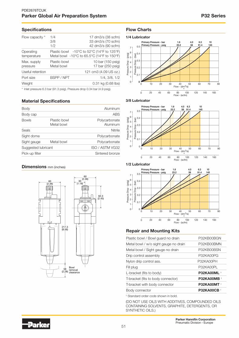
51
Parker Hannifin CorporationPneumatic Division - Europe
PDE2676TCUK
Parker Global Air Preparation System
Flow ChartsSpecifications
Flow capacity * 1/4 17 dm3/s (38 scfm) 3/8 33 dm3/s (70 scfm) 1/2 42 dm3/s (90 scfm)
Operating Plastic bowl -10°C to 52°C (14°F to 125°F) temperature Metal bowl -10°C to 65.5°C (14°F to 150°F)
Max. supply Plastic bowl 10 bar (150 psig) pressure Metal bowl 17 bar (250 psig)
Useful retention 121 cm3 (4.09 US oz.)
Port size BSPP / NPT 1/4, 3/8, 1/2
Weight 0.31 kg (0.68 lbs)
* Inlet pressure 6.3 bar (91.3 psig). Pressure drop 0.34 bar (4.9 psig).
Material Specifications
Body Aluminum
Body cap ABS
Bowls Plastic bowl Polycarbonate Metal bowl Aluminum
Seals Nitrile
Sight dome Polycarbonate
Sight gauge Metal bowl Polycarbonate
Suggested lubricant ISO / ASTM VG32
Pick-up filter Sintered bronze
Repair and Mounting Kits
Plastic bowl / Bowl guard no drain P32KB00BGN
Metal bowl / w/o sight gauge no drain P32KB00BMN
Metal bowl / Sight gauge no drain P32KB00BSN
Drip control assembly P32KA00PG
Nylon drip control ass. P32KA00PH
Fill plug P32KA00PL
L-bracket (fits to body) P32KA00ML †
T-bracket (fits to body connector) P32KA00MB †
T-bracket with body connector P32KA00MT †
Body connector P32KA00CB †
Pre
ssur
e D
rop
- (b
ar)
Pre
ssur
e D
rop
- (p
sig)
0
2
4
6
5
3
1
7
0
0.1
0.2
0.3
0.4
0.5
1.623.2
Primary Pressure - barPrimary Pressure - psig
4.058
6.391.4
10145
00
0
10 20 30 40 50 60 70 80
Flow - (scfm)20 40 8060 100 120 140 160
Flow - (dm3/s) n
1/4 Lubricator
Pre
ssur
e D
rop
- (b
ar)
Pre
ssur
e D
rop
- (p
sig)
0
2
4
6
5
3
1
7
0.1
0.2
0.3
0.4
0.5
1.623.2
Primary Pressure - barPrimary Pressure - psig
4.058
6.391.4
10145
00
0
10 20 30 40 50 60 70 80
Flow - (scfm)20 40 8060 100 120 140 160
Flow - (dm3/s) n
3/8 Lubricator
Pre
ssur
e D
rop
- (b
ar)
Pre
ssur
e D
rop
- (p
sig)
0
2
4
6
5
3
1
7
00
0
10 20 30 40 50 60 70 80
Flow - (scfm)20 40 8060 100 120 140 160
0.1
0.2
0.3
0.4
0.5
1.623.2
Primary Pressure - barPrimary Pressure - psig
4.058
6.391.4
10145
Flow - (dm3/s) n
1/2 Lubricator
† Standard order code shown in bold.
(DO NOT USE OILS WITH ADDITIVES, COMPOUNDED OILS CONTAINING SOLVENTS, GRAPHITE, DETERGENTS, OR SYNTHETIC OILS.)
Dimensions mm (inches)
P32 Series
60(2.36)
60(2.36)
62.3(2.45)
217.3(8.56)
30(1.18)
58(2.28)
Bowlremovalclearance

52
Parker Hannifin CorporationPneumatic Division - Europe
PDE2676TCUK
Parker Global Air Preparation System
Standard Lubricator - P33
Port size Description Flow ‡
dm3/s (scfm)Max.bar (psig)
Heightmm (inches)
Widthmm (inches)
Depthmm (inches) Part number ◊
1/2" Poly bowl - No drain 52 (110) 10 (150) 234 (9.21) 73 (2.9) 73 (2.9) P33LA14LGNN
1/2" Metal bowl - No drain 52 (110) 17 (250) 234 (9.21) 73 (2.9) 73 (2.9) P33LA14LSNN
3/4" Poly bowl - No drain 71 (150) 10 (150) 234 (9.21) 73 (2.9) 73 (2.9) P33LA16LGNN
3/4" Metal bowl - No drain 71 (150) 17 (250) 234 (9.21) 73 (2.9) 73 (2.9) P33LA16LSNN
• Integral 1/2" or 3/4" ports (NPT & BSPP)
• Robust but lightweight aluminum construction
• Proportional oil delivery over a wide range of air flows
• Finger tip ratchet control for precise oil drip rate adjustment
• Fill from top under system pressure
• Oil mist standard sight dome
• No drain closed end
‡ Flow with 6.3 bar (91.3 psig) inlet pressure and 0.34 bar (4.9 psig) pressure drop.◊ For thread type: BSPP 1 NPT 9
Symbol
1 2
Lubricatorwith drain
P33 Series
Order Code for Ordering

53
Parker Hannifin CorporationPneumatic Division - Europe
PDE2676TCUK
Parker Global Air Preparation System
Pre
ssur
e D
rop
- (b
ar)
Pre
ssur
e D
rop
- (p
sig)
0
2
4
6
5
3
1
7
00
0
10 20 30 40 9050 60 100 11070 12080
Flow - (scfm)20 40 8060 100 120 140 240200 220180160
0.1
0.2
0.3
0.4
0.5
1.623.2
Primary Pressure - barPrimary Pressure - psig
4.058
6.391.4
10145
Flow - (dm3/s) n
Pre
ssur
e D
rop
- (b
ar)
Pre
ssur
e D
rop
- (p
sig)
0
2
4
6
5
3
1
7
00
0
10 20 30 40 9050 60 100 11070 12080
Flow - (scfm)20 40 8060 100 120 140 240200 220180160
0.1
0.2
0.3
0.4
0.5
1.623.2
Primary Pressure - barPrimary Pressure - psig
4.058
6.391.4
Flow - (dm3/s) n
Specifications
Flow capacity * 1/2 52 dm3/s (110 scfm) 3/4 71 dm3/s (150 scfm)
Operating Plastic bowl -10°C to 52°C (14°F to 125°F) temperature Metal Bowl -10°C to 65.5°C (14°F to 150°F)
Max. supply Plastic bowl 10 bar (150 psig) pressure Metal bowl 17 bar (250 psig)
Useful retention 181 cm3 (6.1 US oz.)
Port size BSPP / NPT 1/2, 3/4
Weight 0.47 kg (1.04 lbs)
* Inlet pressure 6.3 bar (91.3 psig). Pressure drop 0.34 bar (4.9 psig).
Material Specifications
Body Aluminum
Body cap ABS
Bowls Plastic bowl Polycarbonate Metal bowl Aluminum
Seals Nitrile
Sight dome Polycarbonate
Sight gauge Metal bowl Polycarbonate
Suggested lubricant ISO / ASTM VG32
Pick-up filter Sintered bronze
Plastic bowl / Bowl guard no drain P33KA00BGN
Metal bowl / w/o sight gauge no drain P33KA00BMN
Metal bowl / Sight gauge no drain P33KA00BSN
Drip control assembly P32KA00PG
Nylon drip control ass. P32KA00PH
Fill plug P32KA00PL
L-bracket (fits to body) P33KA00ML †
T-bracket (fits to body connector) P32KA00MB †
T-bracket with body connector P32KA00MT †
Body connector P32KA00CB †
Lubricator oil - VG15: ISO 3448 - 100 ml P3XKA00PPA †
Lubricator oil - VG32 - 1 litre P3YKA00PPBB †
1/2 Lubricator
3/4 Lubricator
† Standard order code shown in bold.
(DO NOT USE OILS WITH ADDITIVES, COMPOUNDED OILS CONTAINING SOLVENTS, GRAPHITE, DETERGENTS, OR SYNTHETIC OILS.)
Dimensions mm (inches)
Flow Charts
Repair and Mounting Kits
P33 Series
73(2.90) 73
(2.90)
51(2.00)
234(9.20)
36(1.44)
51(2.00)
Bowlremovalclearance

54
Parker Hannifin CorporationPneumatic Division - Europe
PDE2676TCUK
Parker Global Air Preparation System Proportional Regulators
Energy SavingLow Watt Power Consumption
No Unnecessary Loss of Air in Steady State
Total Flexibility
User Friendly and Easily Accessible Software Control
One Basic Unit Suits All Customer Requirements - 0-10V Control Signal Standard 4-20mA Control Signal Software Selectable
Modular Mounting
10, 7 & 2 bar Versions
Special Applications
Clean Line Design
Suitable for Washdown: IP65
Forced Exhaust Option Available
4 Output Signal Versions Available
Compact and Light Weight40 & 60 mm Body Sizes
Light Weight Aluminum Bodies
Flexible Mounting Options
Stand-alone or Modular Mounting
Foot Bracket Mounting Outstanding Performance
Very Fast Response Times
Full Flow Exhaust
Excellent Linearity
High Flow
Man-Machine InterfaceHigh Visibility LED Display
Easy to Read Characters
All Controls on the Same Face

55
Parker Hannifin CorporationPneumatic Division - Europe
PDE2676TCUK
Parker Global Air Preparation System
Typical Application in Automotive Body in White Welding Pressure Control
Why Proportional Technology ?The Difference Between Open or Closed Circuit ControlStandard pressure regulators go a long way towards meeting customers needs. In most cases these regulators work well in general pneumatic and automation applications. However, sometimes the application calls for more precise pressure control. The effects of time, cycling, input, back pressure or pressure and flow variation can all cause inconsistencies in pneumatic systems. Proportional Regulators are designed to eliminate those inconsistencies.
Open Control CircuitIn a normal pressure regulated control system, the inlet pressure (p1) is converted into the output pressure (p2) by the regulator. The set pressure (set value) is usually manually set by adjusting the control knob and in normal circumstances the regulator maintains the output pressure (actual value).
No facility for monitoring the output pressure is provided and there is consequently no way of checking that the set value and the actual value are the same. Also, no account is taken of external influences such as air consumption by the system, which can drastically alter the actual value.
Closed Loop Control Circuit The input signal (Electronic Control Signal) is converted into the output value (P2 Output Pressure). This output value is continuously measured and compared with the input signal. If they are different, the unit adjusts the output value to correspond to the set value, to close the loop.
Proportional Pressure RegulatorsThe Proportional Regulators provide all the advantages of a closed circuit regulated system. When a set value is defined via the input signal (e.g. 0-10 V), the pressure regulator sets the corresponding output pressure (e.g. 0-150 PSI/0-10 bar). At the same time the integrated pressure sensor measures the actual pressure at the unit’s outlet (actual value).
If the electronic regulation system finds that the actual value has deviated from the set value, it immediately corrects the actual value. This is a continuous process ensuring fast, accurate pressure regulation.
Proportional Regulators

56
Parker Hannifin CorporationPneumatic Division - Europe
PDE2676TCUK
Parker Global Air Preparation System
P31P SeriesBottom exhaust
P32P SeriesBottom exhaust
• Very fast response times
• Accurate output pressure
• Micro parameter settings
• Selectable I/O parameters
• Quick, full flow exhaust
• LED display indicates output pressure
• No air consumption in steady state
• Multiple mounting options
• Protection to IP65
Proportional Regulators - P31P & P32P
Proportional Regulators
† When the supply voltage is lost the unit will automatically exhaust the regulated pressure to 0 bar (atmospheric pressure)
Version Bottom ported exhaust (NC) A Bottom ported forced exhaust (NO) † E Side ported exhaust (NC) B Side ported forced exhaust (NO) † C
Thread typeBSPP 1NPT 9
Port sizeGlobal modular mini (1/4") 2Global modular compact (1/2") 4
Pressure rangeZ 0 - 2 bar (0-29 PSIG)
S 0 - 7 bar (0-101 PSIG)D 0 - 10 bar (0-145 PSIG)
Power supply2 24 volts
Control signalV 0-10V‡
A 4 - 20mA
Input connector1 M12 (4-pin)
Output signalD Digital, PNPP PNP or 0-10VN NPN or 0-10VM 4-20mA fixed
Body sizeGlobal modular mini (1/4") P31PAGlobal modular compact (1/2") P32PA
D) Digital PNP output only, no analog output selectable
P) Digital PNP and analogue 0-10V outputs selectable, by means of parameter 6. (Factory default 0-10V)
N) Digital NPN and analog 0-10 V outputs selectable by means of parameter 6. Factory default 0-10V)
M) Analog 4-20mA output only.
Note: On all analog outputs the F.S. value can be adjusted by means of parameter 8.
Port size Description Flow ‡
dm3/s (scfm)Max.bar (psig)
Heightmm (inches)
Widthmm (inches)
Depthmm (inches) Part number
1/4"Bottom ported exhaust (NC) - 0-10V - Digital PNP
19 (40) 10 (150) 126.25 (4.99) 57 (2.25) 40 (1.58) P31PA12AD2VD1A
1/4"Bottom ported exhaust (NC) - 4-20mA - Digital PNP
19 (40) 7 (100) 126.25 (4.99) 57 (2.25) 40 (1.58) P31PA12AS2AD1A
1/4"Bottom ported exhaust (NC) - 0-10V - Digital PNP
19 (40) 7 (100) 126.25 (4.99) 57 (2.25) 40 (1.58) P31PA12AS2VD1A
1/4"Bottom ported exhaust (NC) - 0-10V - PNP or 0-10V
19 (40) 10 (150) 126.25 (4.99) 57 (2.25) 40 (1.58) P31PA12AD2VP1A
1/4"Bottom ported forced exhaust (NO) - 0-10V - PNP or 0-10V
19 (40) 10 (150) 126.25 (4.99) 57 (2.25) 40 (1.58) P31PA12ED2VP1A
1/4"Bottom ported forced exhaust (NO) - 0-10V - Digital PNP
19 (40) 10 (150) 126.25 (4.99) 57 (2.25) 40 (1.58) P31PA12ED2VD1A
1/2"Bottom ported exhaust (NC) - 0-10V - Digital PNP
57 (120) 10 (150) 175.7 (6.94) 75 (2.96) 57.2 (2.26) P32PA14AD2VD1A
1/2"Bottom ported exhaust (NC) - 0-10V - 4-20mA fixed
57 (120) 10 (150) 175.7 (6.94) 75 (2.96) 57.2 (2.26) P32PA14AD2VM1A
1/2"Bottom ported exhaust (NC) - 0-10V - PNP or 0-10V
57 (120) 10 (150) 175.7 (6.94) 75 (2.96) 57.2 (2.26) P32PA14AD2VP1A
1/2"Bottom ported forced exhaust (NO) - 0-10V - 4-20mA fixed
57 (120) 10 (150) 175.7 (6.94) 75 (2.96) 57.2 (2.26) P32PA14ED2VM1A
‡ Flow with 6.3 bar (91.3 psig) inlet pressure and 0.2 (3 psig) pressure drop.
Order Code for Ordering
P3 PA 2 1 A
Standard order code shown in bold.
Options:

57
Parker Hannifin CorporationPneumatic Division - Europe
PDE2676TCUK
Parker Global Air Preparation System
Schematic
Technical Information
Working medium Compressed air or inert gasses, filtered to 40µ.
Supply pressure Max. Operating Pressure: 2 bar unit: ............................. 3 bar (43.5 psig)10 bar unit: ........................... 10.5 bar (152 psig)Min. Operating Pressure ....... P2 Pressure + 0.5 bar (7.3 psig)
Pressure control rangeAvailable in three pressure ranges, 0-2 bar (0-29 psig), 0-7 bar (0-101.5 psig) or 0-10 bar (0-145 psig). Pressure range can be changed through the software at all times. (parameter 19)
Flow CapacityP31P flows to 19 dm3/s (40 scfm)P32P flows to 57 dm3/s (120 scfm)
Temperature range 0°C up to +50°C (32°F up to 122°F)
Weights:P31P = 0.291 kg (0.64 lbs)P32P = 0.645 kg (1.42 lbs)
Air consumptionNo consumption in stable regulated situation.
DisplayThe regulator is provided with a digital display, indicating the output pressure, either in bar or psig.The factory setting is as indicated on the label, can be changed through to software at all times (parameter 14)
Supply voltage24 VDC +/- 10%
Power consumptionMax. 1.1W with unloaded signal outputs
Control signalsThe electronic pressure regulator can be externally controlled through an analogue control signal of either 0-10V or 4-20mA. (parameter 4).
Output signalsAs soon as the output pressure is within the signal band asignal is given of 24VDC, PNP Ri = 1 kOhmOutside the signal band this connection is 0V.
Connections(In case of output signal (Option D)Central M12 connector 4-pole The electrical connections are as follows:
Pin No. Function Color
1 24 V Supply Brown
20 to 10 V Control Signal Ri = 100k W
White4 to 20mA Control Signal Ri = 500 W
3 0 V (GND) Supply Blue
4 24 V Alarm Output Signal Black
Proportional Regulators
Cables
P31P Mounting brackets P32P Mounting brackets
L-Bracket Foot BracketL-Bracket Foot Bracket
Description Part number
L-Bracket mounting kit P3HKA00ML
Foot bracket mounting kit P3HKA00MC
Description Part number
2 mtr. cable with moulded straight M12x1 connector
P8L-MC04A2A-M12
2 mtr. cable with moulded 90 degree M12x1 connector
P8L-MC04R2A-M12
Note:These brackets fit both Proportional Regulators and Combined Soft Start & Dump Valves. Dimensions see page 60.
Description Part number
L-Bracket mounting kit P3KKA00ML
Foot bracket mounting kit P3KKA00MC

58
Parker Hannifin CorporationPneumatic Division - Europe
PDE2676TCUK
Parker Global Air Preparation System
Advanced functionalityTechnical information
Flow Charts
P32P Regulator 1/2” Ports
P31P Regulator 1/4” PortsInlet Pressure - 10 bar (145 psig)
Sec
onda
ry P
ress
ure
- ba
r
Sec
onda
ry P
ress
ure
- (p
sig)
0
20
40
60
80
100
120
140
0
2
3
4
5
6
7
8
9
10
1
0
5 10 15 20 25 30 35Flow - dm3/s
Flow - (scfm)10 20 30 40 50 60 70
Inlet Pressure - 10 bar (145 psig)
Sec
onda
ry P
ress
ure
- ba
r
Sec
onda
ry P
ress
ure
- (p
sig)
0
20
40
60
80
100
120
140
0
2
3
4
5
6
7
8
9
10
1
0
0 60 7010 504020 80 9030 100Flow - dm3/s
Flow - (scfm)20 6040 80 100 120 140 180160 200
Response time P31P P32P
2 to 4 bar 25 msecs 35 msecs1 to 6 bar 55 msecs 135 msecs4 to 2 bar 70 msecs 85 msecs6 to 1 bar 80 msecs 225 msecs
To fill volume of:100cm3 - P31P330cm3 - P32Pconnected to the outlet of the regulator.
Pilot valve protection When the required output pressure can not be achieved because of a lack of input pressure the unit will open fully and will display NoP. Approximately every 10 seconds the unit will retry. The output pressure will then be approximately equal to the inlet pressure. As soon as the input pressure is back on the required level, the normal control function follows.
Safety exhaust Should the control signal fall below 0.1 volts the valve will automatically dump downstream system pressure .
Input protection The unit has built-in protection against failure and burnout resulting from incorrect input value, typically:
The 24VDC supply is incorrectly connected to the setpoint input, the display will show ‘OL’, as an overload indication. The unit will need to be rewired and when correctly connected will operate normally.
The overload indicator ‘OL’ will also appear should the wrong input value be applied or the wrong input value be programmed: 4 - 20m instead of 0 - 10V. To correct this a different set point value should be input or the unit reprogrammed to correct the set point value acceptance. (via parameter 4).
Dead band The dead band is preset at 1.3% of Full Scale*, adjustable via parameter 13.
Accuracy Linearity: = < 0.3% of Full Scale.*
Proportional band The proportional band is preset at 10% of Full Scale.*
Fail safe operation • If the P31P / P32P unit has an “0” or “A” in the 12th digit of the model number – When the supply voltage drops, the electronic control reverts to the fail safe mode. The last known output pressure is maintained at approximately the same level depending upon air consumption. The digital display indicates the last known pressure setting. – When the supply voltage is reinstated to the correct level, the valve moves from the fail safe mode and the output pressure immediately follows the control signal requirement. The display indicates the actual output pressure. – Note: In the event of loss of both power and inlet pressure the unit will exhaust downstream pressure.
• If the P31P / P32P unit has an “E” in the 12th digit of the model number – When the supply voltage drops, the electronic control reverts to “Forced Exhaust Mode” and will automatically exhaust the downstream (regulated) pressure.
– When the supply voltage is reinstated to the correct level the unit will return to normal operation and follows the control signal requirement. The display indicates the actual pressure.
• If the unit has been programmed in manual mode (not with a control signal) the unit will EXHAUST and the regulator will need to be reset when power is applied.
Full exhaust Complete exhaust of the regulator is defined as P2 ≤ 1% Full Scale
* Full scale (F.S.) For 2 bar (29 psig) versions this will be 2 bar (29 psig), for the 10 bar (145 psig) version full scale will be 10 bar (145 psig).
Degree of protection IP65
EU conformity CE: standard EMC: according to directive 89/336/EEC The new pressure regulator is in accordance with: EN 61000-6-1:2001 EN 61000-6-2:2001 EN 61000-6-3:2001 EN 61000-6-4:2001
These standards ensure that this unit meets the highest level of EMC protection.
Mounting position Preferably vertical, with the cable gland on top.
Materials: P31P & P32P • Magnet Core .................................................................Steel• Solenoid Valve Poppet .................................................. FPM• Solenoid Valve Housing ................................Techno Polymer• Regulator Body (P31P & P32P versions) ............... Aluminum• Regulator Top Housing ................................................Nylon• Valve Head ....................................................... Brass & NBR• Remaining Seals ........................................................... NBR
SettingsThe regulator is pre-set at the factory. If required, adjustments can be made.
Proportional Regulators

59
Parker Hannifin CorporationPneumatic Division - Europe
PDE2676TCUK
Parker Global Air Preparation System
Dimensions are in mm (Inches)
P31P P32P
L-Bracket L-Bracket
Foot Bracket
7(0.28)
7(0.28)
7(0.28)
25(0.98)
15(0.59)
30(1.18)
30(1.18)
36(1.42)
30(1.18)
45(1.77)
15(0.59)
15(0.59)
36(1.42)
15(0.59) 25
(0.98)
40(1.57)
84(3.31)
52(2.05)
56(2.20)
26(1.02)
100(3.94)
12(0.47)
52(2.05)
Ø 7(0.28)4 holes
Foot Bracket
10(0.39)
12(0.47)
100(3.94)
84(3.31)
40(1.57)
56(2.20)
26(1.02)
52(2.05)
52(2.05) Ø 7
(0.28)4 holes
20(0.79) 28.6
(1.13)
28.6(1.13)
175.7(6.94)
75(2.96)
37.5(1.48)
64.4(2.54)
105.3(4.16)
57.2(2.26)
14.3(0.56)
14.3(0.56)
4 pin M12Connector
4 pin M12Connector
20(0.79)
126.25(4.99)
57(2.25)
28.5(1.12)
37.25(1.47)
89(3.51)
40(1.58)
Proportional Regulators

60
Parker Hannifin CorporationPneumatic Division - Europe
PDE2676TCUK
Parker Global Air Preparation System
SymbolDump Valve
Remotely operated dump valves automatically shut off upstream pressure and exhaust the downstream pressure when the pilot pressure is released.
To maintain these units in the open position a pilot supplyto the air pilot operated version or an electrical signal tothe solenoid operated version must be maintained. The valve will automatically dump when the holdingsignal is removed.
• Modular design with 1/4" or 1/2" integral ports (NPT & BSPP)
• The 3-way, 2-position function automatically dumps downstream pressure on the loss of pilot signal
• Solenoid or air pilot options
• High flow & exhaust capability
• Silencer included
• P32 unit used for both P32 & P33 series
P31D / P32D Series
Solenoid type only
Actuator interfaceG 15mm solenoid (P31 only)C 30mm solenoidP Threaded Air Pilot
Thread type
BSPP 1NPT 9
Port sizeGlobal modular mini (1/4") 2Global modular compact (1/2") 4
Pilot typeP External air pilotS Solenoid pilot
Body sizeDump valve (1/4") P31DADump valve (1/2") P32DA
Solenoid type
0None (For P32 series -
operator is fitted to valve)C 15mm (P31 series only)A 30mm CNOMO coil (P32 only)
D30mm CNOMO coil
(M12 connection) (P32 only)
Solenoid voltage000 Solenoid / Coil not fitted2CN 24VDC non locking manual overide3GN 120VAC non locking manual overide
1FN120VAC non locking manual override
(P31 series only)
Port size Description Flowdm3/s (scfm)
Max.bar (psig)
Heightmm (inches)
Widthmm (inches)
Depthmm (inches)
Weightkg (lbs) Part number
1/4" Solenoid operated (not included) 17 (36) 10 (150) 115.6 (4.5) 57 (2.2) 40 (1.5) 0.37 (0.8) P31DA12SGN0000
1/4" 24VDC Solenoid & cable plug 17 (36) 10 (150) 166‡ (6.5) 57 (2.2) 40 (1.5) 0.41 (0.9) P31DA12SGNC2CN
1/4" External air pilot operated 17 (36) 17 (250) 115.6 (4.5) 57 (2.2) 40 (1.5) 0.37 (0.8) P31DA12PPN
1/2" Solenoid operated (not included) 51 (108) 10 (150) 162.5‡ (6.3) 75 (2.9) 57.2 (2.2) 0.69 (1.5) P32DA14SCN0000
1/2" 24VDC 30mm coil & cable plug incl. 51 (108) 10 (150) 227.5‡ (8.9) 75 (2.9) 57.2 (2.2) 0.91 (2.0) P32DA14SCNA2CN
1/2" External air pilot operated 51 (108) 17 (250) 162.5‡ (6.3) 75 (2.9) 57.2 (2.2) 0.87 (1.9) P32DA14PPN
‡ Includes exhaust silencer
Order Code for Ordering
P3 DA N
Standard order code shown in bold.
Options:

61
Parker Hannifin CorporationPneumatic Division - Europe
PDE2676TCUK
Parker Global Air Preparation System
P31D P32D
40(1.57)
4(0.15)
24(0.94)
37(1.45)
57(2.24)
84(3.30)
1/8"GaugePort 1/4"
GaugePort
30.5(1.20)
136(5.35)
166(6.53)
64.5(2.53)
2.87(73)
227.3(8.95)
174.5(6.87)
2.95(75)
1.02(26)
0.23(6)2.25
(57.2)
53(2.08)
109.5(4.31)
P31DA 1/4" Remote Dump Valve
P32DA 1/2" Remote Dump Valve
For mounting brackets see page 77.
Technical Information
Fluid: Compressed air
Max. pressure solenoid operated: 10 bar (150 psig)
Max. pressure air pilot operated: 17 bar (250 psig)
Min. operating pressure: 3 bar (44 psig)
Temperature Max.* solenoid operated: -10°C to 50°C (14°F to 122°F)
Temperature Max.* air pilot operated: -20°C to 80°C (-4°F to 176°F)
Air pilot port: 1/8"
Exhaust port: P31D - 1/4" / P32D - 1/2"
Gauge port: P31D - 1/8" / P32D - 1/4"
Typical flow with 6.3 bar inlet pressure and 1 bar P31D 17 dm3/s (36 scfm) pressure drop: P32D 51 dm3/s (108 scfm)* Air supply must be dry enough to avoid ice formation at temperatures below +2°CSnap pressure: Full flow when downstream pressure reaches 50% of the inlet pressure
Body: Aluminum
Body cover: Polyester
Seals: Nitrile NBR
Part number Description P31D
L-bracket mounting kit P3HKA00ML
Foot bracket mounting kit P3HKA00MC
Material Specifications
Mounting Brackets
Note:For solenoid operators and cable plugs (connectors) see pages 66 to 67.
Dimensions Pneumatic version dimensions without solenoid mm (inches)
Flow Charts
Inlet Pressure - 6.3 bar (91.3 psig)
Sec
onda
ry P
ress
ure
- (b
ar)
Sec
onda
ry P
ress
ure
- (p
sig)
0
20
40
60
80
100
2
3
4
5
6
7
8
1
0
0
10 15 25 55 60 706535 455 3020 40 50
Flow - (scfm)20 40 60 80 100 120 140
10 bar145 psig
5.0 bar72.5 psig4.0 bar
58 psig3.0 bar43.5 psig
7 bar101.5 psig
8.0 bar116 psig
9.0 bar130.5 psig
6.0 bar87 psig
6.3 bar91.4 psig
Flow - (dm3/s) n
Inlet Pressure - 6.3 bar (91.3 psig)
Sec
onda
ry P
ress
ure
- (b
ar)
Sec
onda
ry P
ress
ure
- (p
sig)
0
20
40
60
80
100
0
2
3
4
5
6
7
8
1
0
0
20 40 1008060 140 150120
Flow - (scfm)40 160 200 24012080 280 320
8.0 bar116 psig
9.0 bar130.5 psig
10 bar145 psig
4.0 bar58 psig
5.0 bar72.5 psig
6.0 bar87 psig
6.3 bar91.4 psig
7 bar101.5 psig
3.0 bar43.5 psig
Flow - (dm3/s) n
P31D / P32D Series

62
Parker Hannifin CorporationPneumatic Division - Europe
PDE2676TCUK
Parker Global Air Preparation System
SymbolSoft Start Valve
Parker Global Series Soft Start Valves, provide for the safe introduction of pressure to machines or systems. Soft Start Valves, allow the pressure to gradually build to the set point before fully opening to deliver full flow at line pressure.
The controlled introduction of pressure can be an important safety factor and prevent damage to tooling when air pressure is introduced at machine or system start up.
Note: Soft Start Valves must be installed downstream of a 3/2 valve with exhaust capability
• Modular design with 1/4" or 1/2" integral ports (NPT & BSPP)
• The 2-way, 2-position function provides for the safe introduction of pressure
• Adjustable slow start
• Solenoid or air pilot options
• High flow
• P32 unit used for both P32 & P33 series
Solenoid type only
Thread type
BSPP 1NPT 9
Port sizeGlobal modular mini (1/4") 2Global modular compact (1/2") 4
Body sizeSoft start P31SASoft start P32SA
Solenoid voltage000 Solenoid / Coil not fitted2CN 24VDC non locking manual overide3GN 120VAC non locking manual overide
1FN120VAC non locking manual override
(P31 series only)
Solenoid type
0None (For P32 series -
Operator is fitted to valve)C 15mm (P31 series only)A 30mm CNOMO coil (P32 only)
D30mm CNOMO coil
(M12 connection) (P32 only)
Actuator interface0 Internal PilotG 15mm solenoid (P31 only)C 30mm solenoidP* Threaded air pilot
Pilot typeP External air pilotS Solenoid pilotY Internal air pilot
P31S / P32S Series
Port size Description Flowdm3/s (scfm)
Max.bar (psig)
Heightmm (inches)
Widthmm (inches)
Depthmm (inches)
Weightkg (lbs) Part number
1/4" Solenoid operated (not included) 17 (36) 10 (150) 115.6 (4.5) 57 (2.2) 40 (1.5) 0.37 (0.8) P31SA12SGN0000
1/4" 24VDC Solenoid & cable plug 17 (36) 10 (150) 166.0 (6.5) 57 (2.2) 40 (1.5) 0.41 (0.9) P31SA12SGNC2CN
1/4" Internal air pilot operated 17 (36) 17 (250) 115.6 (4.5) 57 (2.2) 40 (1.5) 0.37 (0.8) P31SA12Y0N
1/4" External air pilot (1/8" threaded) 17 (36) 17 (250) 115.6 (4.5) 57 (2.2) 40 (1.5) 0.37 (0.8) P31SA12PPN
1/2" Solenoid operated (not included) 48 (101) 10 (150) 162.5 (6.3) 88 (3.4) 57.2 (2.28) 0.87 (1.5) P32SA14SCN0000
1/2" 24VDC 30mm coil & cable plug 48 (101) 10 (150) 227.5 (8.9) 88 (3.4) 57.2 (2.28) 0.90 (2.0) P32SA14SCNA2CN
1/2" Internal air pilot operated 48 (101) 17 (250) 162.5 (6.3) 75 (2.9) 57.2 (2.28) 0.90 (2.0) P32SA14Y0N
1/2" External air pilot (1/8 threaded) 48 (101) 17 (250) 162.5 (6.3) 75 (2.9) 57.2 (2.28) 0.87 (1.5) P32SA14PPN
Order Code for Ordering
P3 SA N
Standard order code shown in bold.
Options:

63
Parker Hannifin CorporationPneumatic Division - Europe
PDE2676TCUK
Parker Global Air Preparation System
P31SA 1/4" Soft Start Valve
100%
90%
4
3
21
Time (t)
Pre
ssur
e (p
)
0% Start signal1
2
3
4
Switching time delayGradual pressure build upOperating pressure p2 (=p1)
P32SA 1/2" Soft Start Valve
For mounting brackets see page 77.
Technical Information
Fluid: Compressed air
Max. pressure solenoid operated: 10 bar (150 psig)
Max. pressure air pilot operated: 17 bar (250 psig)
Min. operating pressure: 3 bar (44 psig)
Temperature Max.* solenoid operated: -10°C to 50°C (14°F to 122°F)
Temperature Max.* air pilot operated: -20°C to 80°C (-4°F to 176°F)
Air pilot port: 1/8"
Gauge port: P31S - 1/8" / P32S - 1/4"
Typical flow with 6.3 bar inlet pressure and 1 bar P31S 17 dm3/s (36 scfm) pressure drop: P32S 48 dm3/s (101 scfm)* Air supply must be dry enough to avoid ice formation at temperatures below +2°CSnap pressure: Full flow when downstream pressure reaches 50% of the inlet pressure
Body: Aluminum
Body cover: Polyester
Seals: Nitrile NBR
Material Specifications
Mounting BracketsDescription Part number P31S
L-bracket mounting kit P3HKA00ML
Foot bracket mounting kit P3HKA00MCNote:For solenoid operators and cable plugs (connectors) see pages 66 to 67.
Dimensions mm (inches) Pneumatic version dimensions without solenoid
Flow Charts
Inlet Pressure - 6.3 bar (91.3 psig)
Sec
onda
ry P
ress
ure
- (b
ar)
Sec
onda
ry P
ress
ure
- (p
sig)
0
20
40
60
80
100
2
3
4
5
6
7
8
1
0
0
10 15 25 55 60 6535 455 3020 40 50
Flow - (scfm)20 40 60 80 100 120
10 bar145 psig
5.0 bar72.5 psig4.0 bar
58 psig3.0 bar43.5 psig
7 bar101.5 psig
8.0 bar116 psig
9.0 bar130.5 psig
6.0 bar87 psig
6.3 bar91.4 psig
Flow - (dm3/s) n
Inlet Pressure - 6.3 bar (91.3 psig)
Sec
onda
ry P
ress
ure
- (b
ar)
Sec
onda
ry P
ress
ure
- (p
sig)
0
20
40
60
80
100
0
2
3
4
5
6
7
8
1
0
0
20 40 1008060 140120
Flow - (scfm)40 160 200 24012080 280
8.0 bar116 psig
9.0 bar130.5 psig
10 bar145 psig
4.0 bar58 psig
5.0 bar72.5 psig
6.0 bar87 psig
6.3 bar91.4 psig
7 bar101.5 psig
3.0 bar43.5 psig
Flow - (dm3/s) n
Soft Start Function:
P31S / P32S Series
- +5 - +5
P31S P32S
40(1.57)
37(1.45)
57(2.24)
136(5.35)
166(6.53)
64.5(2.53)
88(3.46)
174.5(6.87)
75(2.95)
57.2(2.25)
109.5(4.31)
1/8"GaugePort
1/4"GaugePort

64
Parker Hannifin CorporationPneumatic Division - Europe
PDE2676TCUK
Parker Global Air Preparation System
Symbol
Parker Global Series Combined Soft Start / Dump Valves, provide for the safe introduction of pressure to machines or systems. Soft Start / Dump Valves when set, allow the pressure to gradually build to the set point before fully opening to deliver full flow at line pressure.
The controlled introduction of pressure can be an important safety factor and prevent damage to tooling when air pressure is introduced at machine or system start up.
To maintain these units in the open position a pilot supply to the air pilot operated version or an electrical signal to the solenoid operated version must be maintained. The valve will automatically dump when the holding signal is removed.
Combined Soft Start / Dump Valve
• Modular design with 1/4" or 1/2" integral ports (NPT & BSPP)
• Provides for the safe introduction of pressure
• The 3-way, 2-position function automatically dumps downstream pressure on the loss of pilot signal
• Adjustable slow start
• Solenoid or air pilot options
• High flow & exhaust capability
• Silencer included
• P32 unit used for both P32 & P33 series
Solenoid type only
Actuator interfaceG 15mm solenoid (P31 only)C 30mm solenoidP Threaded air pilot
Thread typeBSPP 1NPT 9
Port sizeGlobal modular mini (1/4") 2Global modular compact (1/2") 4
Pilot typeP External air pilotS Solenoid pilot
Body sizeSoft start / dump valve (1/4") P31TASoft start / dump valve (1/2") P32TA
Solenoid voltage000 Solenoid / Coil not fitted2CN 24VDC non locking manual overide3GN 120VAC non locking manual overide
1FN120VAC non locking manual override
(P31 series only)
Solenoid type
0None (For P32 series -
Operator is fitted to valve)
C 15mm (P31 series only)A 30mm CNOMO coil (P32 only)
D30mm CNOMO coil
(M12 connection) (P32 only)
P31T / P32T Series
Port size Description Flow ‡
dm3/s (scfm)Max.bar (psig)
Heightmm (inches)
Widthmm (inches)
Depthmm (inches)
Weight kg (lbs) Part number
1/4" Solenoid operated (not included) 17 (36) 10 (150) 115.6 (4.5) 57 (2.2) 40 (1.5) 0.37 (0.8) P31TA12SGN0000
1/4" 24VDC Solenoid & cable plug 17 (36) 10 (150) 166‡ (6.5) 57 (2.2) 40 (1.5) 0.41 (0.9) P31TA12SGNC2CN
1/4" External air pilot operated 17 (36) 17 (250) 115.6 (4.5) 57 (2.2) 40 (1.5) 0.37 (0.8) P31TA12PPN
1/2" Solenoid operated (not included) 46 (97) 10 (150) 162.5‡ (6.3) 88 (3.4) 57.2 (2.2) 0.87 (1.9) P32TA14SCN0000
1/2" 24VDC 30mm coil & cable plug incl. 46 (97) 10 (150) 227.5‡ (8.9) 88 (3.4) 57.2 (2.2) 0.91 (2.0) P32TA14SCNA2CN
1/2" External air pilot operated 46 (97) 17 (250) 162.5‡ (6.3) 75 (2.9) 57.2 (2.2) 0.87 (1.9) P32TA14PPN
‡ Includes exhaust silencer. Flow with 6.3 bar (91.3) psig) inlet and 1 bar (14.5 psig) pressure drop.
Order Code for Ordering
P3 TA N
Standard order code shown in bold.
Options:

65
Parker Hannifin CorporationPneumatic Division - Europe
PDE2676TCUK
Parker Global Air Preparation System
- +5
P31T P32T
40(1.57)
4(0.15)
24(0.94)
37(1.45)
57(2.24)
84(3.30)
30.5(1.20)
136(5.35)166
(6.53)
- +5
64.5(2.53)
73(2.87)
227.3(8.95)
174.5(6.87)
75(2.95)
26(1.02)
6(0.23)57.2
(2.25)
53(2.08)
109.5(4.31)
1/8"GaugePort
1/4"GaugePort
Part number Description P31T
L-bracket mounting kit P3HKA00ML
Foot bracket mounting kit P3HKA00MC
Technical Information
Fluid: Compressed air
Max. pressure solenoid operated: 10 bar (150 psig)
Max. pressure air pilot operated: 17 bar (250 psig)
Min. operating pressure: 3 bar (44 psig)
Temperature Max.* solenoid operated: -10°C to 50°C (14°F to 122°F)
Temperature Max.* air pilot operated: -20°C to 80°C (-4°F to 176°F)
Air pilot port: 1/8"
Exhaust port: P31T - 1/4" / P32T - 1/2"
Gauge port: P31T - 1/8" / P32T - 1/4"
Typical flow with 6.3 bar inlet pressure and 1 bar P31T 17 dm3/s (36 scfm) pressure drop: P32T 48 dm3/s (101 scfm)
* Air supply must be dry enough to avoid ice formation at temperatures below +2°CSnap pressure: Full flow when downstream pressure reaches 50% of the inlet pressure
Body: Aluminum
Body cover: Polyester
Seals: Nitrile NBR
Material Specifications
P31TA 1/4" Soft Start & Dump Valve
P32TA 1/2" Soft Start & Dump Valve
Note:For solenoid operators and cable plugs (connectors) see pages 66 to 67.
100%
90%
4
3
21
Time (t)
Pre
ssur
e (p
)
0%Start signal1
2
3
4
Switching time delayGradual pressure build upOperating pressure p2 (=p1)
Mounting Brackets
For mounting brackets see page 77.
Dimensions mm (inches) Pneumatic version dimensions without solenoid
Flow Charts
Inlet Pressure - 6.3 bar (91.3 psig)
Sec
onda
ry P
ress
ure
- (b
ar)
Sec
onda
ry P
ress
ure
- (p
sig)
0
20
40
60
80
100
2
3
4
5
6
7
8
1
0
0
10 15 25 55 60 6535 455 3020 40 50
Flow - (scfm)20 40 60 80 100 120
10 bar145 psig
5.0 bar72.5 psig
4.0 bar58 psig3.0 bar
43.5 psig
7 bar101.5 psig
8.0 bar116 psig
9.0 bar130.5 psig
6.0 bar87 psig
6.3 bar91.4 psig
Flow - (dm3/s) n
Inlet Pressure - 6.3 bar (91.3 psig)
Sec
onda
ry P
ress
ure
- (b
ar)
Sec
onda
ry P
ress
ure
- (p
sig)
0
20
40
60
80
100
0
2
3
4
5
6
7
8
1
0
0
20 40 1008060 140120
Flow - (scfm)40 160 200 24012080 280
8.0 bar116 psig
9.0 bar130.5 psig
10 bar145 psig
4.0 bar58 psig
5.0 bar72.5 psig
6.0 bar87 psig
6.3 bar91.4 psig
7 bar101.5 psig
3.0 bar43.5 psig
Flow - (dm3/s) n
P31T / P32T Series

66
Parker Hannifin CorporationPneumatic Division - Europe
PDE2676TCUK
Parker Global Air Preparation System
Solenoid Operator - CNOMO
Order Code for Ordering
Operator Type 2 CNOMO 22 x 30 Plastic
P
Materials
NC Normal Operator NC Normal Operator with 30 x 30 with 22 x 30 standard coil standard coil Working pressure 0 to10 bar 0 to 10 barAmbient temperature -10 °C to 60 °C (1) -10 °C to 60 °C (1)
Orifice 1.3/1.5mm 1.3/1.5mmFlow Qn 0.84 dm3/s 0.84 dm3/sPower (DC) 2.7W 4.8WPower (AC) 4.9VA 8.5VAVoltage tolerance +/- 10% +/- 10% Duty cycle 100% 100% Insulation class F FElectric connection Form A Industrial BProtection IP65 IP65Shock & Vibration 1g 1gApproval UL/CSAWorking media All neutral media such as compressed air and inert gases.
Technical data -Solenoid operators, coil combinations
Pilot Valve
Body: Polyamide Armature tube: Brass Plunger & core: Corrosion resistant Cr-Ni steel Seals: FKM (Viton™) Screws: Stainless steel
CoilEncapsualtion material: Thermoplastic as standard Duroplast for M12 connection
TransientsInterrupting the current through the solenoid coil producesmomentary voltage peaks which, under unfavourable conditions, can amount to several hundred times the rated operating voltage. Nor-mally, these transients do not cause problems, but to achievethe maximum life of relays in the circuit (and particularly oftransistors, thyristors and integrated circuits) it is desirable toprovide protection by means of voltage-dependent resistors(varistors). All connectors/cable plugs EN175301-803 with LED’sinclude this type of circuit protection.
(1) limited to 50°C if use with 100% duty cycle
2 F P 2 3 N 4 B
Pressure / Temp N 10 bar / -10OC to +50OC
Manual / Override B Non locking - monostable - Flush - Brass
Solenoid coils with M12 connectionVoltage Order code Form A W (Kg) Order code Form B W (Kg) 30 x 30 22 x 30
Direct current24V DC P2FC6419 0.065 P2FC7419 0.065
Solenoid coils with Din A or Industrial B connection
* P2FCA453 is compatible with 110 V AC and 48 V DC #P2FCA469 is 24 V DC 6.8W or 48 V 50Hz 9.9 VA
Spare Solenoid OperatorsSolenoid pilot operator CNOMO NC
Note.Solenoid pilot operators are fitted to the Global range. Order the above part numbers for spares. The operators are supplied with mounting screws and interface ‘O’ rings.Coils and connectors must be ordered separately.
Description Order code Weight (Kg) Non-lock manual override
Standard duty P2FP23N4B 0.065
Voltage 30mm x 30mm 22mm x 30mm Order code DIN A Weight (Kg) Order code Industrial B Weight (Kg) Standard Standard
Direct current12V DC P2FCA445 0.105 P2FCB445 0.09324V DC P2FCA449 0.105 P2FCB449 0.09348V DC P2FCA453 * 0.105 P2FCB451 0.093Alternative current 12V 50/60Hz P2FCA440 0.105 P2FCB440 0.09324V 50/60Hz P2FCA442 0.105 P2FCB442 0.09348V 50/60Hz P2FCA469 # 0.105 110V 50Hz, 120V 60Hz P2FCA453 * 0.105 P2FCB453 0.093230V 50Hz, 230V 60Hz P2FCA457 0.105 P2FCB457 0.093
Spare Solenoid Nuts
Valves requiring captured exhaust shouldbe fitted with plastic knurled nut
Valves with vented exhaust are fitted with diffuser plastic nut
Order code
P2FNP
Order code
P2FND
Solenoid Operators

67
Parker Hannifin CorporationPneumatic Division - Europe
PDE2676TCUK
Parker Global Air Preparation System
Solenoid Connectors / Cable Plugs EN175301-803
Description Order code Order code Order code 15mm Form C 22mm Form B 30mm Form A ISO15217 Industrial ISO4400
Solenoid Coil & Cable Plug Dimensions (mm)
P8C-CP8C-DP8L-C2P8L-C53EV10V10
P8C-D26CP8C-D21EP8C-C26CP8C-C21E
P8L-C226CP8L-C526CP8L-CA26CP8L-C221EP8L-C521E
3EV10V20-243EV10V20-1103EV10V20-230
3EV10V20-24L53EV10V20-110L53EV10V20-230L5
Standard IP65 P8C-C 24V DC P8C-C26C LED and protection IP65 110V AC P8C-C21E LED and protection IP65 Standard IP65 P8C-D 3EV10V10 3EV290V10 without flying lead With LED and protection P8C-D26C 3EV10V20-24 3EV290V20-24 24V AC/DC With LED and protection P8C-D21E 3EV10V20-110 3EV290V20-110 110V AC With LED and protection 3EV10V20-230 3EV290V20-230 230V AC Standard with 2m cable IP65 P8L-C2 Standard with 5m cable IP65 P8L-C5 24V AC/DC, 2m cable P8L-C226C LED and protection IP65 24V AC/DC, 5m cable P8L-C526C 3EV10V20-24L5 3EV290V20-24L5 LED and protection IP65 24V AC/DC, 10m cable P8L-CA26C LED and protection IP65 110V AC/DC, 2m cable P8L-C221E LED and protection IP65 110V AC/DC, 5m cable P8L-C521E 3EV10V20-110L5 3EV290V20-110L5 LED and protection IP65 230V AC, 5m cable 3EV10V20-230L5 3EV290V20-230L5 LED and protection IP65
With standard screw
With cable
Form C Cable plugs
P8C-CP8C-C26CP8C-C21EP8C-DP8C-D26CP8C-D21E
Form C Cable plugs
P8L-C2P8LC5P8L-C226CP8L-C526CP8L-CA26CP8L-C221EP8L-C521E
Form BCable plugs
3EV10V10
15,5
35
25
1 2
18
Ø 5,5
17
12
31
40
20,830
5,5 47,542
32
30 315
28,5
31M
3
P2F - CNOMO - 22 x 30mm
3EV290V10
Form ACable plugs
Solenoid Coils & Cable Plugs
With large headed screw suitable formounting in inaccessible or recess position

68
Parker Hannifin CorporationPneumatic Division - Europe
PDE2676TCUK
Parker Global Air Preparation System
SeriesStandard P3
213
21
3
(optional soft start)
• Easy electrical interface with M12 connectors to safety circuit
• External monitoring provides a cost and space saving advantage
• Solid state pressure sensors provide accurate, fast fault detection
• Quick visual LED indicators on the front of the valve
• Superior seated seal design for longer life
• Safety exhaust outlet is no-maintenance and non-clog by design
• Suitable for stand alone use or modular mounting to P32 or P33 FRL assembly
• High B10 life value
• Fast exhaust times allow for smaller machine footprint
3 B 1 6 E NP3GlobalStandard 3
Thread typeBSPP 1 Output for Solenoid,
M12 Connector Pin2 & 4, common 3 A3 & 4 C2 & 4 D
Output for Sensors, M12 Connector Pin1 & 2, 1 & 4, common 3 A1 & 2, 5 & 4, common 3 B5 & 2, 1 & 4, common 3 C
Sensor MonitoringExternal E
DesignCurrent B
Port size3/4" 1 6
TypeSafety redundant (no soft start)
D
Safety redundant (c/w soft start)
T
Gauge 2
No gauge N
Notes: 1. For 1/2" connections use 1/2" port blocks on standard 3/4" housing. 2. Safety valve supplied with 1/8" gauge port in BSPP threads as
specified for ports. Gauges shipped loose. Note: Mounting and port blocks are sold separately.
Operating informationOperating pressure: 2 to 10 PSIG (30 to 150 bar)
Minimum operating pressure: 30 PSIG (2 bar)
Ambient temperature: 4° to 50°C (40° to 120°F)
Recommended filtration: 40µ
Operating medium: Compressed air
Ingress protection class: IP65
B10 (mio): 10 million switching cycles
B10 d (mio): 20 million switching cycles
Allowable discordance: 150ms
Flow media: Compresses air to ISO 8573-1 Class 7:4:4
Weight kg (lbs): 2.9 (6.5) with soft start 1.9 (4.2) without soft start
The soft start opens to full flow at approximately 60% of input pressure.
Safety Exhaust Valves
Order Code for Ordering:
Standard order code shown in bold.
Safety Exhaust Valves

69
Parker Hannifin CorporationPneumatic Division - Europe
PDE2676TCUK
Parker Global Air Preparation System
General Technical Data
Valve type Externally monitored, redundant, dual poppet
Soft start Optional
Valve function 3/2 way, normally closed
Housing material Cast aluminum
Seals NBR
Fasteners Stainless steel / brass
Silencer Steel, non clog safety design
Electrical Specifications
Operating voltage 24V DC
Electrical connection Two M12 connectors
Switching time 1-2 (ms) 23.3
Switching time 2-3 (ms) 42.7
Duty cycle (%) 100%
Operating voltage (DC) 21.6 to 26.4
Nominal power per solenoid coil at 24V DC (W) +/- 10% 1.2 W per pressure sensor at 24V DC 1.2 W
Externally Monitored (with Soft Start)
Externally Monitored (No Soft Start)
Dimensions mm (inches)
Ports
Standard nominal flow rate
A B C D E F1 → 2 L/min (scfm) * 2 → 3 L/min (scfm) *
Externally Monitored 3/4" 145 (4,100) 265 (7,500)
261.9 80 109.3 36.5 162.3 16.3with soft start (10.31) (3.15) (4.30) (1.44) (6.39) (0.64)
Externally Monitored 3/4" 152 (4,300) 265 (7,500)
178.7 80 109.3 36.5 79.0 16.3no soft start (7.03) (3.15) (4.30) (1.44) (3.11) (0.64)
* Standard nominal flow rate is based on 6 bar input pressure with ∆P = 1 bar
D
E
F
A
B CD
E
F
A
B C
In accordance with EN ISO 13849-1 this safety valve is suitable for use up to Category 4, Ple, sil 3. Certified to cCSAus and bears the CE mark.A product Integration Guide is available to help connect your logic controller to the Parker Safety Exhaust Valve under the Product Support tab at www.parker.com/pdn/safetyvalve
Solenoid M12 Pinouts
Pressure Sensor M12 Pinouts
A
5
1
3
42Sol B Sol A+
-
+ 5
1
3
42Sol B Sol A
C
+
-
5
1
3
42Sol B Sol A
D
+
-
5
1
3
42SWA
SW B
A+
-
5
1
3
42SWA
SWB
B++
-
5
1
3
42
C++
-
SWA
SWB
Mountings
Body Connector P32KA00CB †
T-Bracket w / Body Connector P32KA00MT †
T-Bracket (fits to body connector or port block) P32KA00MB †
Port Block Kits (includes two) 1/2" NPT P32KA94CP 1/2" BSPP P32KA14CP †
3/4" NPT P32KA96CP 3/4" BSPP P32KA16CP †
† Standard order code shown in bold.
Safety Exhaust Valves

70
Parker Hannifin CorporationPneumatic Division - Europe
PDE2676TCUK
Parker Global Air Preparation System Safety Exhaust Valves
* For information on internally monitored safety valves reference Bulletin 0700-B13.
** An integration guide is available to provide further information on connecting the safety valve product to achieve the desired performance level. Please consult Parker and the standard EN ISO 13849-1 for more information.
Safety Exhaust Valve FunctionWhen applications demand a safe environment you can count on safety valves from Parker Hannifin. The P33 family of safety exhaust valves are 3/2 normally closed valves designed to rapidly exhaust compressed air in the event of a fault condition and to provided monitored coverage ensuring safe function. The P33 is available in two distinct styles, internally * or externally monitored. The valve is suitable for use up to Category 4, performance level e. Monitoring is achieved externally via a two channel system connected to a safety interface device. Both valves are available with an adjustable soft start and high flow exhaust to shut your equipment down faster when needed. LED’s provide clear status of main solenoid operation, sensor power and fault condition for quick visual reference.
Externally Monitored Valve, Faults and ResetsThe externally monitored valve has the monitoring done via a PLC or relay which offers a size and cost advantage over internally monitored valves. The integration of a safety interface into the PLC or relay will help determined the achievable category and performance level of the control system. Customers are required to provide the logic function via the safety device. The valve will lock-out to the “safe state” if asynchronous movement of the valve elements occur which will be detected by solid state pressure sensors. To achieve the proper safety rating, the safety PLC or relay must monitor the solid state pressure sensors to ensure they are not in different states for more than 150ms. If the sensors are in different states for longer than 150ms then the programming logic must shut off power to the solenoids and consider it a fault condition. If during operation the externally monitored P33 enters a fault condition the valve will shut off. A separate reset signal must be incorporated into the logic sequence to avoid automatic restart of the valve. The safety exhaust valves are not for use with clutch or brake applications and are designed for use in conjunction with a safety relay or safety PLC for safe monitoring and fault detection.
Achieving Desired Performance Level **The category and performance level (PLr) needed for your machine is determined by a risk assessment of the machinery design and application based on EN ISO 13849-1. The Parker P33 safety valve is designed for those applications requiring a PL of d or e. Please note these levels require other aspects of the system to meet these requirements. As a guide: you can achieve a Cat 4 PL e system by integrating monitoring via a programmable safety rated device. Because the P33 is a mechanical fail-safe device, the monitoring could also be done via a standard PLC and still attain as high as a PL d rating.
Safety relay
PLC for external
monitoring
Reset button
Safety relay
Safety PLC
Reset button
Cat 3, PL d
Cat 4, PL e
Conditions at StartThe Safety exhaust valve starts with inlet 1 closed to outlet 2 by both valve elements A and B. Outlet 2 is open to exhaust 3. Pressure signals at both sensors SA and SB are exhausted and contacts 1 and 2 of sensors SA and SB are connected. The normally closed sensors both provide voltage feedback signals to the external monitoring system.
Normal OperationDuring normal operation the two solenoids are simultaneously energized which actuates both pilots and causes valve elements A and B to shift. Inlet 1 is then connected to outlet 2 via crossflow passages C and D. Exhaust 3 is closed. Sensing pressure signals go to each pressure sensor and become equal to inlet pressure. Both sensors contacts open and no voltage signals are provided to the external monitoring system. This indicates that both sides of the valve actuated as expected.
Detecting a MalfunctionA malfunction in the system or the valve itself could cause one valve element to be open and the other closed. Air then flows past the inlet poppet on valve element A, into crossflow passage D, but is substantially blocked by the spool portion of element B. The large size of the open exhaust passage past element B keeps the pressure at the outlet port below 2% of inlet pressure. Full sensing air pressure from side A goes to sensor SA, and a reduced pressure goes to sensor SB. This full pressure signal causes SA to open. Sensor SB, with a reduced pressure signal, does not open. An external monitoring system can detect the malfunction by monitoring the outputs of the SA and SB sensors. The external monitor system must then react accordingly by shutting down the power to the valve solenoids and any other components deemed necessary to stop the machine.
AB
2 1 31SASB
--+
Output Output
+
AB
12SASB
C D
3--+
Output Output
+
AB
2
C D
31SASB
- -+
OutputOutput
+

71
Parker Hannifin CorporationPneumatic Division - Europe
PDE2676TCUK
Parker Global Air Preparation System
The Machinery Directives’ goal is to protect people and the environment from accidents caused from all types of machinery. Based on the standard EN 13849 [safety of machines; safety-related parts of control systems] these standards build the procedure to assess safety-related control systems.
Required Performance Level (PLr) based on a risk assessment are now commonly used to determine the safety level required for the controls system, for the application of machinery.
Performance Level (PL) based on the original B, 1,2,3,4 safety categories, diagnostic capabilities, Mean time to dangerous failure (MTTFd), and common cause failure (CCF), define safety levels of a given safety function. This ensures that safety is not just focused on component reliability, but instead introduces common sense safety principles such as redundancy, diversity, and fail-safe behavior of safety related control parts.
The new EN 13849 standards of the Machinery Directive dictates the machine is safe when the Performance Level of the safety control circuit is equal to or greater than the Required Performance Level of the application. When determining the required performance level, the greater the risk, the higher the requirements of the control system.
PLr < PL
Determining PLr According to EN 13849-1
The level of each hazardous situation is classified in five Performance levels from a to e. With PL a the control functions contribution to risk reduction is low, while at PL e it is high. The risk graph above can be used as a guideline to determine the required performance level PLr for safety function.
Determining PL According to EN 13849-1
Categories Defined by EN 13849-1
Category Summary
Category B When a fault occurs it can lead to the loss of the safety function.
Category 1 Same that Category B, but loss of the safety function is less likely thanks to a good MTTFd of each channel.
Category 2 System behavior allow that the occurrence of a fault can lead to the loss of the safety function between the checks; the loss of the safety function is detected by the check.
Category 3 A single fault in any of safety related parts does not lead to the loss of the safety function. Whenever reasonably possible the single fault shall be detected at or before the next demand upon the safety function. (Means redundancy)
Category 4 Same as Category 3, but if detection of single fault is not possible on or before the next demand upon the safety, an accumulation of these undetected faults shall not lead to the loss of the safety function. (Means redundancy & check)
Machinery Directive - Overview
Risk Parameters
Safety Exhaust Valves

72
Parker Hannifin CorporationPneumatic Division - Europe
PDE2676TCUK
Parker Global Air Preparation System
FeaturesThe Ball / Lockout Valve shuts off downstream line pressure in the closed position with a 90° turn of the handle. In the closed position, inlet air pressure is blocked and downstream / system air is exhausted through a threaded port. To prevent unauthorized adjustment, the padlock slide may be assembled on either side. It is recommended that this slide is installed after final system assembly.
Note: This padlock slide is a permanent assembly and may not be removed later, any unauthorized tampering will void any warranty claims. The valve can only be locked in the closed position.
Ordering Information Specifications
Operating temperature -40°C to 80°C (-40°F to 176°F)
Max. supply pressure 17 bar (250 psig)
Port size BSPP / NPT 1/4, 3/8, 1/2, 3/4
Weight P31: 0.15 kg (0.33 lbs) P32: 0.36 kg (0.79 lbs) P33: 0.55 kg (1.21 lbs)
Material Specifications
Body Aluminum
Seals PTFE
Ball Stainless Steel
Lockout Tab Zinc Plated Steel
Screw Zinc Plated Steel
Ball Valve / Lockout Valve
◊ For thread type: BSPP 1 NPT 9
Dimensions mm (inches)
Model type
Port size
Exhaust port
Thread type
Flowdm3/s (scfm)
Modular ball valveflow from left to right ◊
P31 1/4" 1/4" BSPP 20 (42.4) P31VB12LBNN
P32 3/8" 1/4" BSPP 90 (190.7) P32VB13LBNN
1/2" 1/4" BSPP 122 (258.5) P32VB14LBNN
P33 1/2" 1/2" BSPP 265 (561.5) P33VB14LBNN
3/4" 1/2" BSPP 320 (678) P33VB16LBNN
Symbol
P31, P32, P33 Series
P31 P32 P33
21(0.82)
20(0.78)
42(1.65)
40(1.57)
71.4(2.81)
50(1.96)
21.4(0.84)
60(2.36)
30(1.18)
60(2.36)
30(1.18)
88(3.46)
73(2.87)
25.4(1.00)
36.5(1.43)
73(2.87)
36.5(1.43)
73(2.87)
82.6(3.25)
98.4(3.87)
36.5(1.44)
1/4 ThreadPort
1/2 ThreadPort
1/4 ThreadPort
(

73
Parker Hannifin CorporationPneumatic Division - Europe
PDE2676TCUK
Parker Global Air Preparation System
Features• Available in 1/4, 1/2 & 3/4 threaded inlet / outlet ports• Two additional top and bottom auxiliary ports standard• Can be mounted anywhere in the FRL system• Flow capacity: ¼ 66 dm3/s, ½ 189 dm3/s, ¾ 305 dm3/s
Manifold and Branch Blocks
Manifold BlocksModel In / Out Auxiliary Auxilliary Thread Order CodeType Port Port Port Type Size Size Size Top BottomP31 1/4" 1/4" 1/4" BSPP P31MA12022NP32 1/2" 1/4" 1/2" BSPP P32MA14024NP33 3/4" 1/4" 1/2" BSPP P33MA16024NFor thread type: BSPP 1 NPT 9
Manifold Block - Dimensions
P31 P33
42(1.66)
Flow
IN OUT
20(0.79)
19(0.74)
40(1.58)
41(1.61)
Top and bottom aux. ports 1/4”
40(1.58)
Top port 1/4” Outlet port 3/4”
Bottom port1/2”
73.0(2.88)
36.5(1.44)
33.0(1.30)
66.0(2.60)
23.9(0.94)
47.8(1.88)
Inlet port 3/4”
Top port 1/4”
Outlet port1/2”
Bottom port 1/2”
60.0(2.36)
30(1.18)
23.9(0.94)
47.8(1.88)
23.9(0.94)
47.8(1.88)
Inlet port 1/2”
P32
P32 1/2" 1/4" 1/4" BSPP P32MD14022N
P32 1/4" 1/4" 1/4" BSPP P32MD12022N
Branch Blocks
Body Aluminium
Materials of Construction55
(2.17)
27.5(1.08)
52(2.05)
58(2.28)
29(1.14)
Outlet Port1/2
27(1.06)
Bottom Port1/4
27.5(1.08)
13.5(0.53)
Max Operating Temperature 65.5°C (150°F)
Max Supply Pressure 20.7 bar (300 psi)
Weight 0.14 kg (0.31 lbs)
Specifications
P31, P32, P33 Series
Max Operating Temperature 65.5°C (150°F)
Max Supply Pressure 20.7 bar (300 psi)
Weight P31: 0.19 kg (0.42 lbs) P32: 0.30 kg (0.66 lbs) P33: 0.34 kg (0.75 lbs)
Body Aluminium
Materials of Construction
Specifications
1/4" 66 dm3/s (140 scfm)
1/2" 189 dm3/s (400 scfm)
3/4" 305 dm3/s (646 scfm)
Flow Capacity Manifold and Branch Blocks

74
Parker Hannifin CorporationPneumatic Division - Europe
PDE2676TCUK
Parker Global Air Preparation System
Digital Pressure Sensor
• Sensor output: PNP Open collector Transistor output, 30VDC, 125mA with Analog output, 4 to 20mA
• Output response time less than 2.0 milliseconds
• RoHS
• Air and non-corrosive gases
• Sensor face includes icons to show sensor programming status
MPS-34 Sensor Only Order Codes
Order code
Pressure range Electrical output Electrical connection 1/8 BSPP male
0-30 inHg (1) PNP with (1) 4-20ma M8, 4 Pin MPS-V34G-PCI
0-145 PSI (1) PNP with (1) 4-20ma M8, 4 Pin MPS-P34G-PCI
MPS-34 Accessories
Description Order code
M8, 4-pin, 2 meter cable CB-M8-4P-2M-PUR
M8, 4-pin, 5 meter cable CB-M8-4P-5M-PUR
Internal circuit for open collectorand analog output wiring
Sensor pin out with analog output
Pin #
1 Brown: 24VDC
2 White: 4 to 20mA
3 Blue: 0VDC
4 Black: PNP Open Collector Output 1
4 2
3 1
PNP Output (Analog (4-20mA)+V (Brown)
Out 1 (Black)
Analog (White)
0V (Blue)Sw
itch
mai
n ci
rcui
t
DC 12~24V± 10%
Max.80mA(4-20mA)
Load
Programming options
Outputs change N.O. / N.C. 4
Units of measure change 4
Hysteresis mode 4
Window comparator mode 4
Auto teach mode 4
Output response time 4
Lockout option 4
Password lockout
Max. value display 4
Min. value display 4
Zero reset 4
Red / Green LED display options 4
Error output mode 4
+-
Reducer Male/Female BSPP for MPS-34 Sensor BSPP Male
Gauge portGauge
port size
C1 C2 E F LWeight
(kg)Order code
P31R/P31H/P31E 1/8 Not concerned
P32R/P32H/P32E 1/4 G1/4 G1/8 5.5 16 9.5 0.006 0178 13 10
P33R/P33E 1/4
With integrated O-Ring seal

75
Parker Hannifin CorporationPneumatic Division - Europe
PDE2676TCUK
Parker Global Air Preparation System
MAX WIN N.C. AUTO
mmHg inHg PSI BAR Kgf kPa
MAX HYS N.O. MANOUT
(�) (�)
Dimensions mm (inches)
Specifications
Vacuum (V) Positive (P)
Pressure range -101.3 to 0 kPa (-14.5 to 0 PSI) -0.1 to 1 Mpa (0 to 145 PSI)
Proof pressure 0.3 Mpa (44PSI) 1.5 Mpa (218 PSI)
Display resolution,Units of measure
0.1, kPa0.001, kgf/cm20.001, bar0.01, PSI0.01, inHg1, mmHg
1, kPa0.01, kgf/cm²0.01, bar0.1, PSI--
Media Air & non-corrosive gases
Pressure port (N) 1/8" NPT male, (G) 1/8 BSPP male both with M5 female port
Operating temperature 32 to 122°F (0 to 50°C)
Storage temperature -4 to 140°F (-20 to 60°C)
Humidity 35 to 85% RH (no condensation)
Electrical connection (C) 4-pin, M8 connector on 150mm lead wire
Power supply 12 to 24VDC ±10%, Ripple (P-P) 10% or less
Display 3 + 1/2 digit, 2 color, 7-segment RED / GREEN LED
Display refresh Timing update : 0.1 ~ 3 sec. (Factory Set Unit: 0.1 sec.)
Switch output Output signal, PNP, Normally open or closed, LED indicator, 125 mA max. output load
Output modes Hysteresis or Window Comparator
Response time ≤ 2.5ms (chattering-proof function: 24ms, 250ms, 500ms, 1000ms and 1500ms selections)
Repeatability ± 0.2% of F.S. ± 1 digit
Output currentOutput current 4 to 20mA; Linearity ±1.0% of F.S.; Maximum load impedance 300Ω at powersupply of 12V; 600Ω at power supply of 12V; Minimum load impedance 50Ω
Thermal error 32 to 122°F (0 to 50°C) 25°C (77°C) + 2% of F.S. or less at range of 32 to 122°F (0 to 50°C)
General protection IP40, CE marked, EMC-EN61000-6-2: 2001
Current consumption 45mA (with no load)
Vibration resistance 10 to 150Hz, Double amplitude 1.5mm, XYZ, 2 hrs.
Shock resistance 980 m/s² (about 10G), 3 times/each directions X, Y, Z
Noise Resistance Vp-p400V, 10 ms, 0.5μs noise simulator
Material Housing: ABS (gray) , Pressure port: Zinc die-cast, Diaphragm: Silicon
Mass 1.45 oz. (45g) with M8 connector
Key Lock Indicator
Output Indicator
Button Button
Setting Button
Pressure UnitDisplay Section
2 Colors, Main DisplaySetting ModeDisplay Section
Hex Flat 10
N: NPT 1/8, with M5 femaleG: G1/8, with M5 female
M5 Female
5.51(140)
1.22(25.4)
1.18(30)

76
Parker Hannifin CorporationPneumatic Division - Europe
PDE2676TCUK
Parker Global Air Preparation System
Order instructions Port Function Setting Order Type size range code A (bar)
PR / 0.1-1 NC ST 1/4 48 G1/4 Break contact 0.1-1 KL3439
PR / 0.1-1 NO ST 1/4 48 G1/4 Make contact 0.1-1 KL3440
PR / 1-10 NC ST 1/8 48 G1/8 Break contact 1-10 KL3437
PR / 1-10 NC ST 1/4 48 G1/4 Break contact 1-10 KL3436
PR / 1-10 NO ST 1/8 48 G1/8 Make contact 1-10 KL3438
PR / 1-10 NO ST 1/4 48 G1/4 Make contact 1-10 KL3435
Order Code for Ordering
Characteristics
Safety pressure relief Pmax 300 bar
Port size G1/8, G1/4
Medium and ambient Tmax +100 OC temperature range
Switch back difference Max. 5 - 15%
Voltage Max. 48 V
Current 0.5 A
Degree of protection IP 65
Switching frequency Max. 200 s/min
Analog Pressure Sensors
Material
Housing Passivated steel
Diaphragm Buna N
Switching function
Make contact Closes the circuit when the set pressure is reached
Break contact Interrupts the circuit when the set pressure is reached
Dimensions in mm
Break contact Make contact
Plug can be turned 90O
View Awithout plug
Order instructions Port Function Setting Order Type size range code A (bar)
PR / 0.2-1 NO SR 1/4 48 G1/4 Make contact 0.2-1 KL3445
PR / 0.1-1 NC SR 1/4 48 G1/4 Break contact 0.1-1 KL3454
PR / 0.1-1 NO SR 1/4 48 G1/4 Make contact 0.1-1 KL3455
PR / 1-10 NC SR 1/8 48 G1/8 Break contact 1-10 KL3452
PR / 1-10 NC SR 1/4 48 G1/4 Break contact 1-10 KL3451
PR / 1-10 NO SR 1/8 48 G1/8 Make contact 1-10 KL3453
PR / 1-10 NO SR 1/4 48 G1/4 Make contact 1-10 KL3450
View Awithout protective cap
Protective cap can be turned 6 x 60O

77
Parker Hannifin CorporationPneumatic Division - Europe
PDE2676TCUK
Parker Global Air Preparation System
Port Block Kit (O-ring not shown)
1/8 NPT ............. P31KA91CP1/4 NPT ............ P31KA92CP3/8 NPT ............. P31KA93CP1/8 BSPP ........... P31KA11CP †
1/4 BSPP ........... P31KA12CP †
3/8 BSPP ........... P31KA13CP †
† Standard order code shown in bold.
Accessories - P31 Series
Port Block Kit w/ T-Bracket (O-ring not shown)
1/8 NPT .................P31KA91CN1/4 NPT ................P31KA92CN3/8 NPT .................P31KA93CN1/8 BSPP ...............P31KA11CN †
1/4 BSPP ..............P31KA12CN †
3/8 BSPP ...............P31KA13CN †
† Standard order code shown in bold.
C-Bracket (Fits to filter and lubricator body)
P31KA00MW
T-Bracket w/ Body Connector (O-ring not shown)
P31KA00MT (0, 03kg)
Angle Bracket (Fits to regulator and filter/regulator body)
P31KB00MR - with Plastic Nut
P31KB00MS - with Metal Nut
Body Connector (O-ring not shown)
P31KA00CB (0, 02kg)
68(2.68)42.5(1.67)
10(.39)
6.6(.26)
62(2.44)
60(2.36) 40
(1.57)
40(1.57)
2(.08)
19.3(.76)
35.5(1.40)
Dia
36(1.42)
10(.39)
24(.94)
7(.28)
5.5(.22)
10(.39)
10(.39)
16(.63)
90(3.54)
2.67(68)
1.20(30.4)
Dia.
1.73(44)
0.98(25)
0.67(17)
1.57(40)
2.40(61)
0.27(7)

78
Parker Hannifin CorporationPneumatic Division - Europe
PDE2676TCUK
Parker Global Air Preparation System
Accessories - P32 Series
T-Bracket w/ Body ConnectorP32KA00MT (0, 19kg)
Body ConnectorP32KA00CB (0, 15kg)
Port Block Kit1/4 NPT ................P32KA92CP3/8 NPT ................P32KA93CP1/2 NPT ................P32KA94CP3/4 NPT ................P32KA96CP1/4 BSPP ............P32KA12CP †
3/8 BSPP .............P32KA13CP †
1/2 BSPP .............P32KA14CP †
3/4 BSPP .............P32KA16CP †
† Standard order code shown in bold.
T-Bracket (fits to body connector or port block)
P32KA00MB
Angle Bracket (Fits to regulator and filter/regulator bonnet)
P32KB00MR - with Plastic NutP32KB00MS - with Metal Nut
L-Bracket (Fits to filter and lubricator body)
P32KA00ML
22.1(.87)
8.9(.35)
Dia.
O-Ring
O-Ring 22.1(.87)
8.9(.35)
Dia.
O-Ring
115(4.53)
25.4(1.00)
7.5(.29) (Typ.)
19(.75)
7.0(.28)
20(.79 )
69.5(2.74)
42(1.66)
72(2.84)
22(.88)
28(1.10)
32(1.26)
57(2.25)
7.1(.28)
9.6(.38)
14(.54)
Dia
40(1.57)
42.2(1.66)
72(2.83)
69.6(2.74)
28.3(1.11)
39.9(1.57)
48.5(1.91)
7.15(.28)
9.5(.37)
13.7(.54)
Dia

79
Parker Hannifin CorporationPneumatic Division - Europe
PDE2676TCUK
Parker Global Air Preparation System
Port Block Kit1/4 NPT ...............P32KA92CP3/8 NPT ...............P32KA93CP1/2 NPT ...............P32KA94CP3/4 NPT ...............P32KA96CP1/4 BSPP ...........P32KA12CP †
3/8 BSPP ............P32KA13CP †
1/2 BSPP ............P32KA14CP †
3/4 BSPP ............P32KA16CP †
† Standard order code shown in bold.
Accessories - P33 Series
T-Bracket w/ Body ConnectorP32KA00MT (0, 19kg)
Body ConnectorP32KA00CB (0, 15kg)
T-Bracket (fits to body connector or port block)
P32KA00MB
Angle Bracket (Fits to regulator and filter/regulator bonnet)
P33KA00MR
L-Bracket (Fits to filter and lubricator body)
P33KA00ML
22.1(.87)
8.9(.35)
Dia.
O-Ring
O-Ring22.1(.87)
8.9(.35)
Dia.
O-Ring
40(1.57)
115(4.53)
25.4(1.00)
7.5(.29) (Typ.)
19(.75)
7.0(.28)
20(.79 )
76(2.99)
48(1.89)
84.5(3.33)
25(98)
49(1.92)
61(2.40)
61(2.40)
11(.43)
14(.55)
Dia
76(3.00)
48(1.88)
87(3.44)
28(1.10)
28(1.10)
38(1.49)
67.5(2.66)
7.1(.28)
9.6(.38)
14(.56)
Dia

80
Parker Hannifin CorporationPneumatic Division - Europe
PDE2676TCUK
Parker Global Air Preparation System
Safety Guide For Selecting And Using Pneumatic Division Products And Related Accessories
WARNING:FAILURE OR IMPROPER SELECTION OR IMPROPER USE OF PNEUMATIC DIVISION PRODUCTS, ASSEMBLIES OR RELATED ITEMS (“PRODUCTS”) CAN CAUSE DEATH, PERSONAL INJURY, AND PROPERTY DAMAGE. POSSIBLE CONSEQUENCES OF FAILURE OR IMPROPER SELECTION OR IMPROPER USE OF THESE PRODUCTS INCLUDE BUT ARE NOT LIMITED TO:• Unintended or mistimed cycling or motion of machine members or failure to cycle• Work pieces or component parts being thrown off at high speeds.• Failure of a device to function properly for example, failure to clamp or unclamp an associated item or device.• Explosion• Suddenly moving or falling objects.• Release of toxic or otherwise injurious liquids or gasses. Before selecting or using any of these Products, it is important that you read and follow the instructions below.
1. GENERAL INSTRUCTIONS 1.1. Scope: This safety guide is designed to cover general guidelines on the installation, use, and maintenance of Pneumatic Division
Valves, FRLs (Filters, Pressure Regulators, and Lubricators), Vacuum products and related accessory components. 1.2. Fail-Safe: Valves, FRLs, Vacuum products and their related components can and do fail without warning for many reasons. Design all
systems and equipment in a fail-safe mode, so that failure of associated valves, FRLs or Vacuum products will not endanger persons or property.
1.3 Relevant International Standards: For a good guide to the application of a broad spectrum of pneumatic fluid power devices see: ISO 4414:1998, Pneumatic Fluid Power – General Rules Relating to Systems. See www.iso.org for ordering information.
1.4. Distribution: Provide a copy of this safety guide to each person that is responsible for selection, installation, or use of Valves, FRLs or Vacuum products. Do not select, or use Parker valves, FRLs or vacuum products without thoroughly reading and understanding this safety guide as well as the specific Parker publications for the products considered or selected.
1.5. User Responsibility: Due to the wide variety of operating conditions and applications for valves, FRLs, and vacuum products Parker and its distributors do not represent or warrant that any particular valve, FRL or vacuum product is suitable for any specific end use system. This safety guide does not analyze all technical parameters that must be considered in selecting a product. The user, through its own analysis and testing, is solely responsible for: • Making the final selection of the appropriate valve, FRL, Vacuum component, or accessory.
• Assuring that all user’s performance, endurance, maintenance, safety, and warning requirements are met and that the application presents no health or safety hazards.
• Complying with all existing warning labels and / or providing all appropriate health and safety warnings on the equipment on which the valves, FRLs or Vacuum products are used; and,
• Assuring compliance with all applicable government and industry standards. 1.6. Safety Devices: Safety devices should not be removed, or defeated. 1.7. Warning Labels: Warning labels should not be removed, painted over or otherwise obscured. 1.8. Additional Questions: Call the appropriate Parker technical service department if you have any questions or require any additional
information. See the Parker publication for the product being considered or used, or call 1-800-CPARKER, or go to www.parker.com, for telephone numbers of the appropriate technical service department.
2. PRODUCT SELECTION INSTRUCTIONS 2.1. Flow Rate: The flow rate requirements of a system are frequently the primary consideration when designing any pneumatic system.
System components need to be able to provide adequate flow and pressure for the desired application. 2.2. Pressure Rating: Never exceed the rated pressure of a product. Consult product labeling, Pneumatic Division catalogs or the
instruction sheets supplied for Maximum pressure ratings. 2.3. Temperature Rating: Never exceed the temperature rating of a product. Excessive heat can shorten the life expectancy of a product
and result in complete product failure. 2.4. Environment: Many environmental conditions can affect the integrity and suitability of a product for a given application. Pneumatic
Division products are designed for use in general purpose industrial applications. If these products are to be used in unusual circumstances such as direct sunlight and/or corrosive or caustic environments, such use can shorten the useful life and lead to premature failure of a product.
2.5. Lubrication and Compressor Carryover: Some modern synthetic oils can and will attack nitrile seals. If there is any possibility of synthetic oils or greases migrating into the pneumatic components check for compatibility with the seal materials used. Consult the factory or product literature for materials of construction.
2.6. Polycarbonate Bowls and Sight Gauges: To avoid potential polycarbonate bowl failures: • Do not locate polycarbonate bowls or sight gauges in areas where they could be subject to direct sunlight, impact blow, or temperatures outside of the rated range.
• Do not expose or clean polycarbonate bowls with detergents, chlorinated hydro-carbons, ketones, esters or certain alcohols. • Do not use polycarbonate bowls or sight gauges in air systems where compressors are lubricated with fire resistant fluids such as
phosphate ester and di-ester lubricants.

81
Parker Hannifin CorporationPneumatic Division - Europe
PDE2676TCUK
Parker Global Air Preparation System
2.7. Chemical Compatibility: For more information on plastic component chemical compatibility see Pneumatic Division technical bulletins Tec-3, Tec-4, and Tec-5
2.8. Product Rupture: Product rupture can cause death, serious personal injury, and property damage. • Do not connect pressure regulators or other Pneumatic Division products to bottled gas cylinders.
• Do not exceed the Maximum primary pressure rating of any pressure regulator or any system component. • Consult product labeling or product literature for pressure rating limitations.3. PRODUCT ASSEMBLY AND INSTALLATION INSTRUCTIONS 3.1. Component Inspection: Prior to assembly or installation a careful examination of the valves, FRLs or vacuum products must be
performed. All components must be checked for correct style, size, and catalog number. DO NOT use any component that displays any signs of nonconformance.
3.2. Installation Instructions: Parker published Installation Instructions must be followed for installation of Parker valves, FRLs and vacuum components. These instructions are provided with every Parker valve or FRL sold, or by calling 1-800-CPARKER, or at www.parker.com.
3.3. Air Supply: The air supply or control medium supplied to Valves, FRLs and Vacuum components must be moisture-free if ambient temperature can drop below freezing
4. VALVE AND FRL MAINTENANCE AND REPLACEMENT INSTRUCTIONS 4.1. Maintenance: Even with proper selection and installation, valve, FRL and vacuum products service life may be significantly reduced
without a continuing maintenance program. The severity of the application, risk potential from a component failure, and experience with any known failures in the application or in similar applications should determine the frequency of inspections and the servicing or replacement of Pneumatic Division products so that products are replaced before any failure occurs. A maintenance program must be established and followed by the user and, at Minimum, must include instructions 4.2 through 4.10.
4.2. Installation and Service Instructions: Before attempting to service or replace any worn or damaged parts consult the appropriate Service Bulletin for the valve or FRL in question for the appropriate practices to service the unit in question. These Service and Installation Instructions are provided with every Parker valve and FRL sold, or are available by calling 1-800-CPARKER, or by accessing the Parker web site at www.parker.com.
4.3. Lockout / Tagout Procedures: Be sure to follow all required lockout and tagout procedures when servicing equipment. For more information see: OSHA Standard – 29 CFR, Part 1910.147, Appendix A, The Control of Hazardous Energy – (Lockout / Tagout)
4.4. Visual Inspection: Any of the following conditions requires immediate system shut down and replacement of worn or damaged components: • Air leakage: Look and listen to see if there are any signs of visual damage to any of the components in the system. Leakage is an indication of worn or damaged components.
• Damaged or degraded components: Look to see if there are any visible signs of wear or component degradation. • Kinked, crushed, or damaged hoses. Kinked hoses can result in restricted air flow and lead to unpredictable system behavior. • Any observed improper system or component function: Immediately shut down the system and correct malfunction. • Excessive dirt build-up: Dirt and clutter can mask potentially hazardous situations. Caution: Leak detection solutions should be rinsed off after use. 4.5. Routine Maintenance Issues:
• Remove excessive dirt, grime and clutter from work areas. • Make sure all required guards and shields are in place. 4.6. Functional Test: Before initiating automatic operation, operate the system manually to make sure all required functions operate
properly and safely. 4.7. Service or Replacement Intervals: It is the user’s responsibility to establish appropriate service intervals. Valves, FRLs and vacuum
products contain components that age, harden, wear, and otherwise deteriorate over time. Environmental conditions can significantly accelerate this process. Valves, FRLs and vacuum components need to be serviced or replaced on routine intervals. Service intervals need to be established based on: • Previous performance experiences.
• Government and / or industrial standards. • When failures could result in unacceptable down time, equipment damage or personal injury risk. 4.8. Servicing or Replacing of any Worn or Damaged Parts: To avoid unpredictable system behavior that can cause death, personal
injury and property damage: • Follow all government, state and local safety and servicing practices prior to service including but not limited to all OSHA Lockout Tagout procedures (OSHA Standard – 29 CFR, Part 1910.147, Appendix A, The Control of Hazardous Energy – Lockout / Tagout).
• Disconnect electrical supply (when necessary) before installation, servicing, or conversion. • Disconnect air supply and depressurize all air lines connected to system and Pneumatic Division products before installation,
service, or conversion. • Installation, servicing, and / or conversion of these products must be performed by knowledgeable personnel who understand how
pneumatic products are to be applied. • After installation, servicing, or conversions air and electrical supplies (when necessary) should be connected and the product
tested for proper function and leakage. If audible leakage is present, or if the product does not operate properly, do not put product or system into use.
• Warnings and specifications on the product should not be covered or painted over. If masking is not possible, contact your local representative for replacement labels.
4.9. Putting Serviced System Back into Operation: Follow the guidelines above and all relevant Installation and Maintenance Instructions supplied with the valve FRL or vacuum component to insure proper function of the system.

Catalogue PDE2676TCUK-V5 09/2020© 2020 Parker Hannifin Corporation. All rights reserved.
Parker Worldwide
Your local authorized Parker distributor
Europe, Middle East, AfricaAE – United Arab Emirates, Dubai Tel: +971 4 8127100 [email protected]
AT – Austria, St. Florian Tel: +43 (0)7224 66201 [email protected]
AZ – Azerbaijan, Baku Tel: +994 50 2233 458 [email protected]
BE/NL/LU – Benelux, Hendrik Ido Ambacht Tel: +31 (0)541 585 000 [email protected]
BG – Bulgaria, Sofia Tel: +359 2 980 1344 [email protected]
BY – Belarus, Minsk Tel: +48 (0)22 573 24 00 [email protected]
CH – Switzerland, Etoy Tel: +41 (0)21 821 87 00 [email protected]
CZ – Czech Republic, Klecany Tel: +420 284 083 111 [email protected]
DE – Germany, Kaarst Tel: +49 (0)2131 4016 0 [email protected]
DK – Denmark, Ballerup Tel: +45 43 56 04 00 [email protected]
ES – Spain, Madrid Tel: +34 902 330 001 [email protected]
FI – Finland, Vantaa Tel: +358 (0)20 753 2500 [email protected]
FR – France, Contamine s/Arve Tel: +33 (0)4 50 25 80 25 [email protected]
GR – Greece, Piraeus Tel: +30 210 933 6450 [email protected]
HU – Hungary, Budaörs Tel: +36 23 885 470 [email protected]
IE – Ireland, Dublin Tel: +353 (0)1 466 6370 [email protected]
IL – Israel Tel: +39 02 45 19 21 [email protected]
IT – Italy, Corsico (MI) Tel: +39 02 45 19 21 [email protected]
KZ – Kazakhstan, Almaty Tel: +7 7273 561 000 [email protected]
NO – Norway, Asker Tel: +47 66 75 34 00 [email protected]
PL – Poland, Warsaw Tel: +48 (0)22 573 24 00 [email protected]
PT – Portugal Tel: +351 22 999 7360 [email protected]
RO – Romania, Bucharest Tel: +40 21 252 1382 [email protected]
RU – Russia, Moscow Tel: +7 495 645-2156 [email protected]
SE – Sweden, Borås Tel: +46 (0)8 59 79 50 00 [email protected]
SK – Slovakia, Banská Bystrica Tel: +421 484 162 252 [email protected]
SL – Slovenia, Novo Mesto Tel: +386 7 337 6650 [email protected]
TR – Turkey, Istanbul Tel: +90 216 4997081 [email protected]
UA – Ukraine, Kiev Tel: +48 (0)22 573 24 00 [email protected]
UK – United Kingdom, Warwick Tel: +44 (0)1926 317 878 [email protected]
ZA – South Africa, Kempton Park Tel: +27 (0)11 961 0700 [email protected]
North AmericaCA – Canada, Milton, Ontario Tel: +1 905 693 3000
US – USA, Cleveland Tel: +1 216 896 3000
Asia PacificAU – Australia, Castle Hill Tel: +61 (0)2-9634 7777
CN – China, Shanghai Tel: +86 21 2899 5000
HK – Hong Kong Tel: +852 2428 8008
IN – India, Mumbai Tel: +91 22 6513 7081-85
JP – Japan, Tokyo Tel: +81 (0)3 6408 3901
KR – South Korea, Seoul Tel: +82 2 559 0400
MY – Malaysia, Shah Alam Tel: +60 3 7849 0800
NZ – New Zealand, Mt Wellington Tel: +64 9 574 1744
SG – Singapore Tel: +65 6887 6300
TH – Thailand, Bangkok Tel: +662 186 7000
TW – Taiwan, Taipei Tel: +886 2 2298 8987
South AmericaAR – Argentina, Buenos Aires Tel: +54 3327 44 4129
BR – Brazil, Sao Jose dos Campos Tel: +55 800 727 5374
CL – Chile, Santiago Tel: +56 2 623 1216
MX – Mexico, Toluca Tel: +52 72 2275 4200
EMEA Product Information CentreFree phone: 00 800 27 27 5374(from AT, BE, CH, CZ, DE, DK, EE, ES, FI, FR, IE, IL, IS, IT, LU, MT, NL, NO, PL, PT, RU, SE, SK, UK, ZA)
US Product Information CentreToll-free number: 1-800-27 27 537
www.parker.com