global guide for designing chilled-beam systems · global guide for designing chilled-beam systems...
TRANSCRIPT

6.75 x 9.8125 inches6.75 x 9.8125 inches
FrontCover
Spin
e= 0
.312
5
Green = Bleed = 0.125” Green = Bleed = 0.125”
Active and Passive Beam Application
Design Guide
Global Guide for Designing Chilled-Beam Systems
The Active and Passive Beam Application Design Guide is the result of collaboration by worldwide experts to give system designers a current, authoritative guide on successfully applying active and passive beam technology. Active and passive beam systems provide energy-efficient methods of cooling, heating, and ventilating indoor areas, especially spaces that require individual zone control and where internal moisture loads are moderate. The systems are simple to operate, with low maintenance requirements.
This book is an essential resource for consulting engineers, architects, owners, and contractors who are involved in the design, operation, and installation of these systems. Building on REHVA’s Chilled Beam Application Guidebook, this new guide provides up-to-date tools and advice for designing, commissioning, and operating chilled-beam systems to achieve a determined indoor climate, and includes examples of active and passive beam calculations and selections. Dual units (I-P and SI) are provided throughout.
ASHRAE Edition.
1791 Tullie Circle Atlanta, GA 30329-2305 Telephone: 404-636-8400 www.ashrae.org
ISBN 978-1-936504-83-1
Product code: 90667 1/159 781936 504831
9 782930 521145
Joint publication of REHVA and ASHRAE
For Global Application
Active and Passive Beam
Application D
esign Guide
Microsoft ®Excel® files for beam calculations provided online.
Active and Passive Design Guide.indd 1 12/5/2014 3:37:15 PM

Active and Passive BeamApplication Design Guide

This publication was developed under the auspices of ASHRAE Technical Committee (TC) 5.3, Room Air Distribution. TC 5.3 is concerned with the distribution, diffusion, and conditioning of air within rooms and similarly treated spaces. It includes consideration of the principles of air distribution, air diffusion, and performance characteristics of all
types of air terminal devices, fan-coils, chilled beams, and high-/low-pressure assemblies (boxes) or components, including associated or related accessories for
both supply and extract air.
EditorsJohn Woollett Julian Rimmer
Co-Chairs of Authoring CommitteePeter Simmonds, PhD
Darren S. Alexander, PEngJonathan Chan
Ken Loudermilk, PEChris Lowell
Jonas AkessonCarlos LisboaRafael Urculo Maija K. Virta
Thomas WoltersRisto Kosonen
Reviewers
This book underwent an independent review process before publishing. The following persons have reviewed the book and made valuable suggestions for improvements:
Birgit Mueller, GermanyJorma Railio, Finland
Jarek Kurnitski, EstoniaLivio Mazzarella, Italy
Updates/errata for this publication will be posted on the ASHRAE website at www.ashrae.org/publicationupdates.

Active and Passive BeamApplication Design Guide
REHVA
Atlanta Brussels
ISBN 978-1-936504-83-1
© 2015 ASHRAE and REHVA
1791 Tullie Circle, NEAtlanta, GA 30329www.ashrae.org
Federation of European Heating, Ventilation and Air Conditioning Associationswww.rehva.eu
All rights reserved.Printed in the United States of America
Cover design by Tracy Becker
ASHRAE is a registered trademark in the U.S. Patent and Trademark Office, owned by the American Society of Heating, Refrigerating and Air-Conditioning Engineers, Inc.
ASHRAE has compiled this publication with care, but ASHRAE has not investigated, and ASHRAE expressly disclaims any duty to investigate, any product, service, process, procedure, design, or the like that may be described herein. The appearance of any technical data or editorial material in this publi-cation does not constitute endorsement, warranty, or guaranty by ASHRAE of any product, service, process, procedure, design, or the like. ASHRAE does not warrant that the information in the publication is free of errors, and ASHRAE does not necessarily agree with any statement or opinion in this publi-cation. The entire risk of the use of any information in this publication is assumed by the user.
No part of this book may be reproduced without permission in writing from ASHRAE, except by a reviewer who may quote brief passages or reproduce illustrations in a review with appropriate credit, nor may any part of this book be reproduced, stored in a retrieval system, or transmitted in any way or by any means—electronic, photocopying, recording, or other—without permission in writing from ASHRAE. Requests for permission should be submitted at www.ashrae.org/permissions.
Library of Congress Cataloging-in-Publication Data
Chilled beam application guidebook Active and passive beam application design guide. pages cm Revision of Chilled beam Application Guidebook, published by REHVA, 2004. This version has I-P units listed first. Includes bibliographical references and index. ISBN 978-1-936504-83-1 (softcover) 1. Chilled beams (Air conditioning) I. ASHRAE (Firm) II. Federation of European Heating and Airconditioning Associations. III. Title. TH7687.78.C46 2015 697.9'312--dc23
2014043062
REHVA STAFF Cynthia Despradel, Editorial Assistant Jarkko Narvanne, Graphic Designer
ASHRAE STAFF SPECIAL PUBLICATIONS Mark S. Owen, Editor/Group Manager of Handbook and Special PublicationsCindy Sheffield Michaels, Managing EditorJames Madison Walker, Associate EditorSarah Boyle, Assistant EditorLauren Ramsdell, Editorial AssistantMichshell Phillips, Editorial Coordinator
PUBLISHING SERVICES David Soltis, Group Manager of Publishing Services and Electronic CommunicationsJayne Jackson, Publication Traffic AdministratorTracy Becker, Graphics Specialist
PUBLISHER W. Stephen Comstock

CONTENTS
1 Preface and Acknowledgments 1
2 Terms and Definitions 2
3 Symbols and Units 3
4 Abbreviations 4
5 Introduction 6
6 Comfort 14
7 Passive Beams 16
8 Active Beams 25
9 Primary Airflow Calculation Methodology 35
10 Controls 44
11 Installation and Commissioning 54
12 System Operation 57
13 Energy and Total Cost of Ownership 58
14 References and Bibliography 61
Appendix A: Examples for I-P Applications 64
Appendix B: Examples for SI Applications 89
Excel files for beam calculations provided online at ashrae.org/beamcalc.


1 PREFACE AND ACKNOWLEDGMENTS
1 Preface and Acknowledgments
1
PREFACEThis design guide is a revision of the REHVA Chilled Beam Application Guidebook, which was pub-
lished in 2004. ASHRAE and REHVA decided to collaborate on a revision of the guidebook and enlisted experts from both organizations to revise the document.
This new guide is aimed at consulting engineers, architects, owners, and contractors who are involved in the design, operation, and installation of active and passive beam systems.
This book provides tools and guidance to design, commission, and operate active and passive beam systems to achieve a determined indoor climate. It also presents examples of active and passive beam calculations and selections. Online tools can be found at ashrae.org/beamcalc.
ACKNOWLEDGMENTSThere are many ASHRAE and REHVA members who should be recognised for their expertise in
realizing this design guide. The following ASHRAE and REHVA experts should be recognised for their diligent help, guidance
and collaboration in producing this design guide.
ASHRAE REHVA
Julian Rimmer (ASHRAE Chair) John Woollett (REHVA Chair)Darren Alexander Jonas ÅkessonKen Loudermilk Carlos LisboaChris Lowell Sawicki SlowomirMick Holland Rafael UrculoPeter Simmonds Maija VirtaJonathan Chan Thomas Wolters
Risto Kosonen

2 TERMS AND DEFINITIONS
The following terms and definitions are based on the CEN and ASHRAE standards for testing and rating of chilled beams. Additional definitions are mainly from the ISSO publication Climatic Ceilings and Beams: Applications of Low Temperature Heating and High Temperature Cooling (2001).
Active and Passive Beam Application Design Guide
2
active beam: a terminal device with an integrated, ducted air supply that induces ambient air through a hydronic coil for the purpose of transferring sensible heat to/from the space.
dew point: the temperature at which water vapour present in the air begins to condense.
draught: unwanted cooling of the body caused by local air movement.
draught rating (DR-value): the percentage of people predicted to be dissatisfied due to draught.
induced airflow: the secondary airflow from the room induced by the primary air in an active beam.
induction ratio (IR): the volume or mass flow rate of induced air (sum of the primary and secondary air) divided by that of the primary air. IR equals .
infiltration: the transport of unconditioned air through leakage paths in the envelope of a building, resulting from pressure (e.g., wind) and temperature differences.
mixed airflow rate: the total airflow rate (primary plus induced) of the mixture supplied from the beam to the space.
mean radiant temperature: the theoretical uniform temperature of a room in which the radiant exchange between the human body and its environment is the same as the radiant exchange in the actual location.
passive beam (static beam): the cooled element or cooling coil fixed in, above, or under a ceiling fitted with a cooling coil, that cools mainly convectively, using natural airflows. The cooling medium is usu-ally water.
primary airflow rate: conditioned air supplied to an active beam through a duct from the air-handlingunit.
room air temperature: the average of air temperatures measured at 3.61 ft (1.1 m) high, positioned out of the main air current from the beam.
turbulence intensity: the ratio of the standard deviation of the air velocity to the mean air velocity. Used to measure variations in air velocity.
Qp Qs+ Qp
3 SYMBOLS AND UNITS
3 Symbols and Units
3
Symbol Quantity Unit: I-P (SI)
cp specific heat capacity, cp = 1 Btu/lbm°F (4.187 kJ/[kg·K]) water, cp = 0.24 Btu/lbm°F (1.005 kJ/[kg·K]) air
L active length of beam ft (m)Lt total length of a beam, including casing ft (m)P total cooling capacity active beam, P = Pa + Pw Btu/h (W)
total cooling capacity passive beam, P = Pw Btu/h (W)Pa primary air cooling capacity, Pa = Qp pcp(ta – tp) Btu/h (W)PL specific cooling capacity of a beam, relative to active length L W/ft (W/m)PLN nominal specific cooling capacity at tN Btu/h·ft (W/m)PN nominal cooling capacity at tN Btu/h (W)Pw water-side cooling capacity, Pw = cp·Qm(tw2 – tw1) Btu/h (W)q thermal load Btu/h (W)Qm water mass flow rate (Qm = w · Qw) lb/min (kg/s)Qp primary airflow rate cfm (m³/s)Qs secondary airflow rate cfm (m³/s)Qw water flow rate cfm (L/s)ta induced air temperature °F (°C)tp primary air temperature °F (°C)tr reference air temperature = room air temperature °F (°C)tw1 water inlet temperature °F (°C)tw2 water outlet temperature °F (°C)tw mean water temperature, tw = 0.5(tw1 + tw2) °F (°C)W humidity ratio (mass water/unit mass dry air) lb/lb (kg/kg) t temperature difference, t = tr – tw °F (K)tN nominal temperature difference °F (K) p density of primary air, 0.075 lb/ft3, 70°F (1.20 kg/m3, t = 21°C) lb/ft3 (kg/m3)w density of water 62.4 lb/ft3 (1000 kg/m3) lb/ft3 (kg/m3)

4 ABBREVIATIONS
Active and Passive Beam Application Design Guide
4
A floor area
ACH, ach air changes per hour
ACHINF infiltration air changes per hour
AHU air-handling unit
Cair cooling by air (primary airflow)
CAPEX capital expenditure
CHWR chilled-water return
CHWS chilled-water supply
CW cooling by water (water coil)
CWTin Beam chilled-water temperature in
DB, db dry-bulb temperature, °F (°C)
DBIDA IDA design condition cooling
DBODA1 ODA design condition cooling
DBODA3 ODA design condition heating
DBSUP primary air temperature
DCV demand-controlled ventilation
DP dew-point temperature, °F (°C)
DPIDA IDA design condition cooling
DPODA2 ODA design condition dehumidification
DPSUP primary air dew point
DR draught rating
dT temperature difference
Enth enthalpy, Btu/lb (kJ/kg)
h ceiling height
HR humidity ratio, lb moisture/lb dry air (g moisture/kg dry air)
HRIDA IDA design condition cooling
HRODA1 ODA design condition cooling
HRODA2 ODA design condition dehumidification
HRSUP primary air humidity ratio

4 Abbreviations
5
HWR hot-water return
HWS hot-water supply
INF infiltration airflow
LCC life-cycle cost
LLAT latent load (dehumidication dsg cdts)
LSENS sensible load (clg design cdts)
MCDBODA2 ODA design condition dehumidification
MCWBODA1 ODA design condition cooling
NP occupancy
OCPL occupant load, lat/p
OCPS occupant load, sens/p
OPEX operating expenditure
OPR owner project requirements
PICV pressure-independent control valve
PMV predicted mean vote
PPD predicted percentage of dissatisfied
Ra ventilation, cfm/ft2 (L/s·m2)
RHIDA IDA design condition cooling
Rp ventilation, per person
SET standard effective temperature
TCO total cost of ownership
V primary airflow
V1 ventilation requirement
V2 airflow for dehumidification
vol volume
w.c. water column
WB, wb wet-bulb temperature, °F (°C)

5 INTRODUCTION
Active and passive beam systems are an energy-efficient solution for spaces that require indi-vidual zone control and where the internal moisture loads are moderate. Active and passive beam systems provide good thermal comfort and energy and space saving advantages. The operation of the system is simple, with low maintenance requirements. Although they are often referred to as “chilled” beams, in many cases active beams can be used for both heating and cooling the space. In this guide, we will refer to them as active or passive beams.
Active and passive beams are room air recirculation devices that transfer sensible heat to and from the space using water. In addition, conditioned primary air is ducted to active beams. This primary air must satisfy the ventilation and latent requirements of the space and drive the induction of room air through the beam’s coil. In the case of passive beams, this primary air is delivered to the space through a decoupled ventilation system. Active and passive beams may be integrated with acoustic ceilings or independently mounted.
Active and Passive Beam Application Design Guide
6
5.1 COMMON APPLICATIONSActive and passive beam systems have specific applications. As a result, each application must
be reviewed for potential benefits as well as the suitability of these types of systems. One consider-ation that can assist in the decision to use hydronic systems, as opposed to an all-air system, is the air-side load fraction, or the percentage of the total air supply that must be delivered to the zone to satisfy code and possible dehumidification requirements. Tables 5-1 and 5-2 show typical load fraction for several spaces. The best applications for beam systems are those with the lowest air-side load frac-tion, because they are the ones that will benefit the most from the efficiencies of hydronic systems. Another factor that should be evaluated is the sensible heat ratio (the percentage of the cooling load which is sensible). To prevent latent removal by the hydronic system, the latent loads must be satis-fied with an air system that will potentially offer some sensible cooling at the same time because of the temperature of dehumidified air. If the total sensible cooling load is significantly higher than the capacity of the air that would need to be supplied to satisfy the latent loads, a beam system might be a good choice.
5.1.1 Commercial Office Buildings
In an office building, active and passive beam systems provide several benefits. The reduced sup-ply air volume required from the air-handling system for ventilation purposes provides significant energy savings. In addition, the smaller infrastructure required for this reduced airflow allows for smaller plenum spaces and mechanical room footprints, translating into shorter floor-to-floor con-struction or higher ceilings and increased usable floor space. The reduced supply air volume and elimination of fans at or near the space offers a significant reduction in generated noise. The mini-mized airflow often translates to reheat requirements being reduced. Figure 5.1 shows a typical office installation.
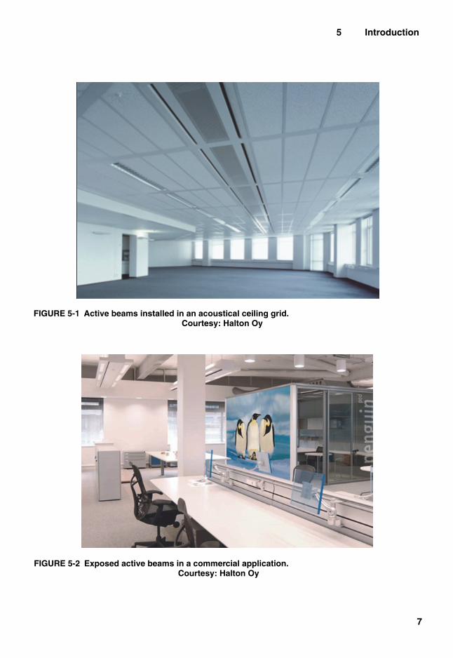
FIGURE 5-1 Active beams installed in an acoustical ceiling grid. Courtesy: Halton Oy
FIGURE 5-2 Exposed active beams in a commercial application.Courtesy: Halton Oy
5 Introduction
7

TAB
LE 5
-1 T
ypic
al V
entil
atio
n R
ate
for
Diff
eren
ce S
pace
s A
ccor
ding
to A
SH
RA
E/E
N S
tand
ards
2007
and
201
0A
SHR
AE
St
anda
rd 6
2.1
Occ
upan
cy
Cat
egor
y
Def
ault
Occ
upan
t Den
sity
, ft
2 /Occ
upan
tA
SHR
AE
62.
1 V
entil
atio
nD
efau
lt
Ven
tila
tion
, cf
m/p
erso
n
Def
ault
V
entil
atio
n,
cfm
/ft2
2010
ASH
RA
EL
EE
D v
2 E
Qc2
—In
crea
se V
enti
lati
on
Req
uire
men
ts
ASH
RA
E
Stan
dard
62.
1,
Num
ber/
1000
ft2
ASH
RA
E
Stan
dard
62.
1 R
p,cf
m/p
erso
nR
a,
cfm
/ft2
Def
ault
, cf
m/p
erso
nD
efau
lt,
cfm
/ft2
ASH
RA
E
Stan
dard
62.
1A
SHR
AE
St
anda
rd 6
2.1
Rat
e,
cfm
/ft2
Gov
erni
ng
Stan
dard
Day
care
(t
hrou
gh a
ge 4
)25
4010
0.18
170.
4317
0.43
0.56
ASH
RA
E
Stan
dard
62.
1
Cla
ssro
oms
(age
9+)
3529
100.
1213
0.46
130.
450.
59A
SHR
AE
St
anda
rd 6
2.1
Lec
ture
cl
assr
oom
6515
7.5
0.06
80.
528
0.52
0.68
ASH
RA
E
Stan
dard
62.
1
Lec
ture
hal
l (f
ixed
sea
ts)
150
77.
50.
068
1.20
81.
21.
56A
SHR
AE
St
anda
rd 6
2.1
Mul
tiuse
ass
embl
y10
010
7.5
0.06
80.
808
0.8
1.04
ASH
RA
E
Stan
dard
62.
1
Res
taur
ant
dini
ng ro
oms
7014
7.5
0.18
100.
7010
0.7
0.91
ASH
RA
E
Stan
dard
62.
1
Caf
eter
ia/
fast
-foo
d di
ning
100
107.
50.
189
0.90
90.
91.
17A
SHR
AE
St
anda
rd 6
2.1
Con
fere
nce/
mee
ting
5020
50.
066
0.30
60.
30.
39A
SHR
AE
St
anda
rd 6
2.1
Off
ice
spac
e5
200
50.
0617
0.09
170.
090.
12A
SHR
AE
St
anda
rd 6
2.1
Ret
ail
1567
7.5
0.12
160.
2416
0.24
0.31
ASH
RA
E
Stan
dard
62.
1
Mal
l com
mon
are
as40
257.
50.
609
0.36
90.
360.
47A
SHR
AE
St
anda
rd 6
2.1
Active and Passive Beam Application Design Guide
8

TABLE 5-2 Typical Load Fractions for Several Spaces from Europe
ApplicationTotal Air Volume,
All-Air System,cfm/ft2 (L/s·m²)
Ventilation Requirement,EN 15251—Cat II /
Low-Pollution Building,cfm/ft2 (L/s·m²)
Air-Side Load Fraction
Single office 1.4 (7) 0.3 (1,4) 0,20
Open-space office 1.3 (6,5) 2.0 (1,2) 0,18
Conference room 2.2 (11) 0.8 (4,2) 0,38
School 2.2 (11) 0.8 (4,2) 0,38
Kindergarten 1.8 (9) 0.8 (4,2) 0,47
Auditorium 2.5 (12,9) 2.0 (10) 0,77
Department store 2.2 (11) 0.3 (1,7) 0,16
Restaurant 2.0 (10) 1.1 (5,4) 0,54
Patient room 1.6 (8) 0.3 (1,6) 0,20
5 Introduction
9
5.1.2 Schools
Schools are another application that can benefit from active and passive beam systems. Similar to office buildings, the benefits of a reduced supply air volume to the space are decreased fan power, lower plenum height, reduced reheat requirements, and lower noise levels (often a critical design parameter of schools).
5.1.3 Hospital Patient Rooms
Hospitals are applications where the outdoor air volume required by local codes and guidelines for each space is often greater than the requirement of the cooling and heating load, because of air quality issues for patients care.
5.1.4 Laboratories
Active and passive beam systems can be suitable in sensible-load-driven laboratories where the supply airflow rate is driven by the internal gains (such as refrigerators, testing equipment, etc.) as opposed to the exhaust requirements. In these environments, it is not unusual to require a large air-change rate in order to satisfy the load, although significantly fewer air changes may be required by code.

Active and Passive Beam Application Design Guide
10
In these applications, the difference between the supply air volume required to manage the sensible loads and that required to meet the fume hood airflow requirements provides opportunity for energy savings through the application of active and passive beams. These savings are typically due to the reduction in fan power as well as the energy associated with treating the outdoor air, which, in the case of a sensible-load-driven lab, may be significant.
5.1.5 Hotels / Dormitories
Hotels, motels, dormitories, and similar buildings can also benefit from active and passive beam systems. Fan power savings often come from the elimination of fan coil units located in the occupied spaces, as a central air-handling unit can have a lower total specific fan power. It also allows for the elimination of the electrical service required for the installation of fan coil units, as well as a reduction in the maintenance of the drain and filter systems. The removal of these fans from the occupied space also provides lower noise levels, which is a significant benefit in sleep areas.
5.1.6 Limitations
There are several possible applications where humidity can be difficult to control, such as lobby areas, kitchens, natatoriums, and spaces where there is a large and/or variable latent load from occu-pants.
Entrance areas may see a significant short-term humidity load if they are not isolated in some way (revolving doors or vestibules). In these areas, if outdoor conditions are very humid, a choice of a com-plementary technology is ideal. This is also more likely if the building envelope has a high infiltration rate and the outdoor conditions are very humid.
5.2 BEAMS TYPES
5.2.1 Passive Beams
Passive beams are characterized by heat transfer from natural convection of room air across the hydronic coil. Natural convection as it relates to passive beams occurs because of buoyancy forces when the cooler surface of the heat exchanger comes in contact with warmer room air; the air cools, its density increases, and the heavier air moves downward into the space.
5.2.2 Active beams
Active beams are characterized by forced convection caused by induction of room air across the hydronic coil. This induction is created by primary air discharged through nozzles at high velocity. The discharge air through the nozzles induces room air, which is heated or sensibly cooled by the coil and then mixed with the primary air. It is recommended that the space ventilation requirements and latent space loads be controlled by the volume and moisture content of the primary air supply.
5.2.3 Multiservice Beams
Typical beam installations deliver air for ventilation and latent cooling, as well as provide heating or sensible cooling for temperature control. In some instances, these can incorporate other building ser-

FIGURE 5-3 Airflow schematic of a passive beam.
FIGURE 5-4 Airflow schematic of an active beam.
5 Introduction
11
vices, such as lighting, power, network cabling, PA, smoke detection, and fire suppression. This consol-idation is typically investigated in order to minimize the disparate elements in the ceiling. These are referred to as multiservice beams and are available with both active and passive beam types.
5.3 BENEFITS OF ACTIVE AND PASSIVE BEAM SYSTEMS
5.3.1 Energy
The heat transfer capacity of water allows for a reduction in the energy used to transport an equiva-lent amount of heat as compared to an all-air system. These reductions can be achieved primarily through reduced fan energy. The higher chilled-water supply (CHWS) temperatures used with active and passive beam systems, typically around 58°F(14.5°C), provide many opportunities for reducing in energy use.

FIGURE 5-5 Exposed passive beams with integrated lighting. Courtesy: Trox
Active and Passive Beam Application Design Guide
12
5.3.2 Beam Efficiencies
Water has a higher transfer efficiency than air because of its energy density characteristics per unit volume when transporting energy to and from a zone. It requires less power to move the necessary cool-ing or heating energy. Because the air volume for an all-air system has airflow volumes which are often significantly higher than ventilation requirements, larger ductwork is required to provide the same cool-ing or heating effect as the same unit volume of water (see Figure 5-6). The specific heat capacity per unit mass of water is 4.2 times higher than the specific heat capacity of standard air. The density of water is approximately 800 times greater than standard air.
5.4 CORRECTION FOR ALTITUDE
All psychrometric properties change with altitude, and this should be taken into account in the cal-culations and beam selection data.
Manufacturers’ performance data, pressure losses, or sound power generated are usually valid for an air density of 0.075 lb/ft3 (1.2 kg/m3) at sea level. Air densities for different altitudes above sea, with correction factors, can be found in the ASHRAE Handbook—Fundamentals.

FIGURE 5-6 Approximate comparison between water and air transporting equivalent energy.
5 Introduction
13
5.5 TESTING AND RATINGTesting of beams is done in accordance with EN 14518, Ventilation for Buildings—Chilled
Beams—Testing and Rating of Passive Chilled Beams (ISO 2005b) (passive) and EN 15116, Ventilation in Buildings—Chilled Beams—Testing and Rating of Active Chilled Beams (ISO 2008) (active) in Europe. In the United States, the appropriate standard is currently under development, ASHRAE Stan-dard 200P, Methods of Testing Chilled Beams, for active beams. Certification programs (Eurovent, AHRI) guarantee accuracy of manufacturers’ technical data.

6 COMFORT
Active and Passive Beam Application Design Guide
14
6.1 THERMAL COMFORTHuman thermal comfort is defined as the state of mind that expresses satisfaction with the surround-
ing environment. Maintaining thermal comfort for occupants of buildings or other enclosures is the most important goal of HVAC design engineers.
Thermal comfort is affected by heat conduction, convection, radiation, and evaporative heat loss. Thermal comfort is maintained when the heat generated by human metabolism is allowed to dissipate, thus maintaining thermal equilibrium with the surroundings. Any heat gain or loss beyond this gener-ates a perception of discomfort. It has been long recognised that the sensation of feeling hot or cold is not just dependent on air temperature alone.
Factors determining thermal comfort include the following:• Personal factors
- Clothing insulation level (Clo value) - Activity levels (metabolic rate)
• General factors affecting the whole body thermal sensation- Air temperature - Mean radiant temperature - Relative humidity - Air velocity
Thermal balance can, depending on activity and clothing, only be achieved within certain environ-mental conditions. For example, at temperature of 75°F (24°C), a person doing work sitting down in an office produces approximately 430 Btu/h (130 W) of total heat, of which 185 Btu/h (55 W) (ASHRAE 2009) is released through evaporation. The remaining heat is emitted through radiation and convection.
To assess whole body thermal comfort, a number of additional and derived quantities are used, such as operative temperature and radiant temperature asymmetry. To predict the statistical average of the space population’s whole body thermal comfort, PMV and predicted percentage of dissatisfied (PPD) indices are used. To predict local thermal comfort, the draught rating (DR) index may be used. Refer to the examples in Chapter 10, Controls.
Standard EN ISO 7730:2005, Ergonomics of the Thermal Environment—Analytical Determination and Interpretation of Thermal Comfort Using Calculation of the PMV and PPD Indices and Local Thermal Comfort (ISO 2005a), and ANSI/ASHRAE Standard 55-2013, Thermal Environmental Condi-tions for Human Occupancy, define these indices and propose methods for predicting thermal sensation. The paramount consideration in sizing and locating the beams in the room should be maintaining ther-mal comfort within the occupied zone. The occupied zone is defined by EN 13779-2007, Ventilation for Non-residential Buildings—Performance Requirements for Ventilation and Room-Conditioning Sys-tems (ECS 2007a), and ANSI/ASHRAE Standard 55-2013.
Indoor climate target values (normally specified in the owner’s project requirements) should be taken into account when defining design values for beam systems. Specific capacity (by beam length) and pri-mary airflow rate should be limited to the range where proper operation conditions and comfortable thermal conditions can be ensured (e.g., by avoiding objectionable velocities in the occupied zone or stratification).

6 Comfort
15
Typical indoor climate target values are as follows:
• –0.5 < PMV < 0.5.
• Localized factors affecting specific exposed body area- Vertical air temperature difference between 3.6 and 0.33 ft (1.1 and 0.1 m) above the floor (level
of head and ankles) <9°F (5°C)- Local air temperature- Air movement/velocity/turbulence- Radiant asymmetry
6.2 ACOUSTICAL COMFORTIndoor sound level strongly influences human comfort. Bad acoustic design contributes to noisy envi-
ronments, which can prevent spaces from being used for their intended purpose.Room design sound pressure levels, generated and/or transmitted by the ventilation or air-conditioning
system in different types of spaces, are defined in national standards. These values are time-averaged room sound pressure levels and apply to sound generated by the air-conditioning system only.
Sound sources, like active beams, generate sound power by airflow through the nozzles. Therefore, the sound power is strongly dependent on primary airflow.

7 PASSIVE BEAMS
Active and Passive Beam Application Design Guide
16
7.1 PRACTICAL GUIDELINESPassive beams provide sensible cooling from the water coil. Heating and ventilation must be han-
dled by complementing systems.Positioning of passive beams is crucial for the following:
• Capacity- Locating the passive beams in consideration of natural movement of room air can optimize beam
output.- Avoid strong heat sources located directly below a passive beam.- Care should be taken to not locate a passive beam too far above the finished floor, as the cool
convective air may not penetrate the occupied zone because of heat gain from room air or sur-faces. Typical height above the finished floor is 15 ft (<4,5m). More detailed analysis is required to verify performance.
• Comfort- The higher the capacity per unit length, the more important the positioning becomes to maintain
acceptable comfort (because of the potential of draught sensation).- Use areas outside the occupied zone to allow the cooled air to mix with the room air before it
reaches the occupants.
7.2 FUNCTIONA passive beam consists of a coil and a casing (Figure 7-1)
FIGURE 7-1 Typical construction of passive beam.
. In some cases, it can include an architectural cover plate such as a perforated face or grille. The coil includes a circuit of copper