glovebox manual
TRANSCRIPT

Gas Purifi er MB20/MB200 G
INER
TGAS
TE
CHNO
LOGY
Operating Manual
with Touch Panel TP700
Workstation LABmaster Pro sp/dp MOD Box with MB20/MB200 G


Gas Purification Systems
� Gas Purifier� Workstation� MOD Box with Touchpanel
Operating Manual
Gas Purification Systems
Gas Purifier MB20/MB200 G Workstation LABmaster Pro sp/dpMOD Box with MB20/MB200 G
Touchpanel TP700
Operating Manual
sp/dp

Original Operating Manual V 4.1 - 06/2014 Gas Purifier MB20/MB200 G Workstation LABmaster sp/dp MOD Box with MB20/MB200 G Touchpanel TP700 M. Braun Inc. 14 Marin Way Stratham, NH 03885 Website www.mbraun.com Phone: +1 (603) 773-9333 Fax. +1 (603) 773-0008 E-Mail [email protected]
Inertgas Systems
Operating Manual
1 Information
2 System
3 Safety
4 Preparation and Installation
5 Structure of the Controller and Touch Panel
6 Basic Principles of Operating Modes
6 A ECO-Mode *
7 Operation of
8 Operation of the Inert Gas Box
8 A Analyzer
9 Operation of
10 Additional Components
11 Trouble Shooting
12 Inspection and Maintenance
13 Spare Parts
14 Third Party Documentation
15 Certificates
16 Electrical / Wiring
* Optional additional chapter
Inertgas Systems
Operating Manual
Information
Preparation and Installation
Structure of the Controller and Touch Panel
Basic Principles of Operating Modes
Mode *
Operation of the Gas Purifying System
Operation of the Inert Gas Box
Analyzer *
Operation of the Antechamber
Additional Components
Trouble Shooting
Inspection and Maintenance
Spare Parts
Third Party Documentation
Certificates
Electrical / Wiring Diagrams
Optional additional chapters
Annexes:
PDF of the Manual and Third Party Documentation (CD-ROM or USB
Contents
V 4.1 – 06/2014
and Third Party ROM or USB-Stick)

1 Information about the Operating Manual
MB20-200-Labmaster – TP700
Operating Manual – V 4.1 – 06/2014 - STD
Page
1-1
1.1 System information ................................................................................1-2 1.1.1 Scope of delivery .................................................................................................... 1-3 1.1.2 Identification Sticker ............................................................................................... 1-3 1.1.3 Safety markings on the system .............................................................................. 1-4
1.2 Use of this operating manual ................................................................1-6 1.2.1 Before use of the inert gas system ......................................................................... 1-6 1.2.2 While the inert gas system is in use ....................................................................... 1-6 1.2.3 Markings in this operating manual .......................................................................... 1-6 1.2.4 Safety instructions .................................................................................................. 1-6
1.3 Liability ...................................................................................................1-9
1.4 Warranty .................................................................................................1-9
1.5 Service address.................................................................................... 1-10

1 Information about the Operating Manual
System information
Page
1-2
MB20-200-Labmaster – TP700
Operating Manual – V 4.1 – 06/2014 - STD
1 Information about the Operating Manual
1.1 System information
This operating manual belongs to the following M.Braun system:
Designation / Type: ………..........................................................................
Serial number(s): ………..........................................................................
System administrator / User: ………..........................................................................
Other system information: ...………………………………………………………………………….
…………………………………………………………………………………………………………………
Notes:
…………………………………………………………………………………………………………………
…………………………………………………………………………………………………………………
…………………………………………………………………………………………………………………
…………………………………………………………………………………………………………………
…………………………………………………………………………………………………………………
…………………………………………………………………………………………………………………
………………………………………………………………………………………………………………………………………………………………………………………………………………………………………
…………………………………………………………………………………………………………………
…………………………………………………………………………………………………………………
…………………………………………………………………………………………………………………
…………………………………………………………………………………………………………………
…………………………………………………………………………………………………………………
…………………………………………………………………………………………………………………
…………………………………………………………………………………………………………………
…………………………………………………………………………………………………………………
…………………………………………………………………………………………………………………
…………………………………………………………………………………………………………………

1 Information about the Operating Manual
Scope of delivery
MB20-200-Labmaster – TP700
Operating Manual – V 4.1 – 06/2014 - STD
Page
1-3
1.1.1 Scope of delivery
The scope of delivery is defined in the contractual agreements according to order confirmation and follow-ups.
This operating manual describes - regardless of the scope of delivery - a typical standard system with
� Inert gas box with antechamber
� Gas purification system
� PLC controller with touch panel
� Sensors for monitoring of the box/antechamber atmosphere
Optional components / functions are marked in the operating manual, such as, e.g.
� Solvent filter
� Vacuum pump
� Antechamber cover lock
See also Chap. 10 Accessories and customer-specific components.
1.1.2 Type plate Rear side of the system: examples of type plates of standard systems
Project-specific systems deviate depending on their equipment.

1 Information about the Operating Manual
System information
Page
1-4
MB20-200-Labmaster – TP700
Operating Manual – V 4.1 – 06/2014 - STD
1.1.3 Safety markings on the system
Devices may bear the following warnings and mandatory signs:
General warning
Indicates possible personal injury, possible damage to the system or accessories and a possible compromising of the process materials!
Risk of hazardous electrical voltage
Indicates possible personal injury due to electrical voltage such as uncontrolled muscle reactions, crippling, burns or death!
Use caution! There is danger to life and limb!
Risk of gases under pressure
Indicates possible personal injury, possible damage to the system or accessories due to gas containers or gas lines!
Risk of hot surface
Do not touch hot surface! Risk of burning!
The markings in this operating manual refer only to devices and components from MBRAUN. Other manufacturers' components may be marked with other safety instructions that are not explained in this operating manual. See supplier documentation Chap. 14.
Duties of the Operator
The system operator is obligated to attach safety markings to the system if dangers results from system expansions or processes. This applies especially to the use of dangerous or toxic chemicals.
DANGER
Risk of injury and damage!
All safety markings on the system must always be visible and legible!

Scope of delivery
MB20-200-Labmaster – TP700
Operating Manual – V 4.1 – 06/2014 - STD
Position of the safety markings on the system (Standard)
1 Information about the Operating Manual
STD
Position of the safety markings on the system (Standard)
Antechamber:
Control cabinet:
with frequency converter:
without frequency converter:
Vacuum pump:
On the side:
(see also supplier documentation)
WARNINGS
Hot surface
Electric shock
Information about the Operating Manual
Page
1-5
Antechamber:
Control cabinet:
with frequency converter:
without frequency converter:
Vacuum pump:
Hot surface
Electric shock

1 Information about the Operating Manual
Use of this operating manual
Page
1-6
MB20-200-Labmaster – TP700
Operating Manual – V 4.1 – 06/2014 - STD
1.2 Use of this operating manual
1.2.1 Before use of the inert gas system
Anybody who works on the system must read, understand, and follow the operating manual while performing any necessary work: this includes transport, storage, installation, commissioning, and servicing.
► Read the instructions completely before using the system in order to avoid improper operation and injuries.
► In case of questions, please contact MBRAUN Service.
1.2.2 While the inert gas system is in use
Always keep the operating manual within reach of the system.
Follow all safety instructions in this manual
! MBRAUN inert gas systems are subject to constant safety-technical enhancement. Therefore it can be that the actual system components differ from those described in the operating manual. In case of doubt, be sure to contact the manufacturer.
1.2.3 Markings in this operating manual
Sequence of actions:
> Prerequisite
► Action
→ Intermediate result / consequence
⇒ Result
! Information and tips (action-related)
Background information
Numbering:
00000-1 Number in panel image
1.2.4 Safety instructions
The safety instructions in this operating manual comply with the guidelines 2006/42/EC, DIN EN ISO 12100-1 and ISO EN 82079, ISO 14121-1, and 2. They are used analogously to ANSI Z535.6.

Scope of delivery
MB20-200-Labmaster – TP700
Operating Manual – V 4.1 – 06/2014 - STD
The following safety instructions are used in this operating manual:
DANGER
Severe to life-threatening injuries. Occurrence very likely to certain.
WARNING
Severe to life-threatening injuries. Occurrence possible.
CAUTION
Slight to moderate injuries. Occurrence possible.
Marking of the type of danger (optional)
If necessary, the type of danger may be marked:
Type of danger – standard systems
Risk of hazardous electrical voltage!
Indicates possible personal injury due to electrical voltage such as uncontrolled muscle reactions, crippling, burns or death!
Use caution! There is danger to
Risk of suffocation
Hot surface
Mechanical hazard!
Indicates injuries to hands and arms due to crushing, bending, cutting, cutting movements, and catching in rotating equipment.
Type of danger – in case of customer
Risk of explosion!
Indicates possible personal injuries due to the handling of flammable or explosive gases.
1 Information about the Operating Manual
STD
The following safety instructions are used in this operating manual:
threatening injuries. Occurrence very likely to certain.
threatening injuries. Occurrence possible.
Slight to moderate injuries. Occurrence possible.
Marking of the type of danger (optional)
danger may be marked:
standard systems
Risk of hazardous electrical voltage!
Indicates possible personal injury due to electrical voltage such as uncontrolled muscle reactions, crippling, burns or death!
Use caution! There is danger to life and limb!
Risk of suffocation
Mechanical hazard!
Indicates injuries to hands and arms due to crushing, bending, cutting, cutting movements, and catching in rotating equipment.
in case of customer-specific equipment/processes
Risk of explosion!
Indicates possible personal injuries due to the handling of flammable or explosive
Information about the Operating Manual
Page
1-7
Indicates possible personal injury due to electrical voltage such as uncontrolled muscle
Indicates injuries to hands and arms due to crushing, bending, cutting, cutting
Indicates possible personal injuries due to the handling of flammable or explosive

1 Information about the Operating Manual
Use of this operating manual
Page
1-8
MB20-200-Labmaster – TP700
Operating Manual – V 4.1 – 06/2014 - STD
Warnings about property damage
NOTICE Note about property damage. Occurrence possible.
Instructions
Wear full breathing protection mask!
Wear protective goggles!
Wear protective gloves!
Type and function of the safety instructions
The safety instructions in this operating manual are used as:
� Basic safety instructions. The essential safety aspects are summarised in the basic safety instructions chapter. They serve as safety instructions before using the inert gas system.
� Preceding safety instructions. At the beginning of a chapter/a sequence of instructions, there are warning signs and signal words. The preceding safety instructions warn about risks of injury that may arise during a sequence of actions.
� Integrated safety instructions. Directly preceding the action are risks of injury that arise during one or several related action(s). The warnings are integrated into the action sequence, and either marked with a signal word or danger sign.

1 Information about the Operating Manual
Scope of delivery
MB20-200-Labmaster – TP700
Operating Manual – V 4.1 – 06/2014 - STD
Page
1-9
1.3 Liability
The contractually agreed-upon liability conditions apply. The manufacturer assumes no liability for product damage or personal injury that results from improper handling or the failure to follow operating manual or safety guidelines.
Designations used in this operating manual may be trademarked product names; these serve only the purpose of identification.
Changes and modifications
The warranty and warranty claims are voided by non-approved changes and modifications!
� Changes and modifications may only be made by MBRAUN specialised personnel. Exceptions require written confirmation.
� The manufacturer assumes no liability for damage due to authorised system modifications or software updates if these were performed improperly or the damage arose due to improper operation because of neglected updating of the operating manual. There are generally no liability claims for unauthorised system modifications.
1.4 Warranty
The warranty is only valid for the contractually-equipped system. Warranty claims are voided under the following conditions:
� Unauthorised changes to the system without the manufacturer's permission
� Improper operation of the system
� Improper use of the system
� Inadequate maintenance of the system
� Carelessness with respect to the system supply
� Use of other manufacturers' components without permission of the system manufacturer
� Changes of programme and system settings without the manufacturer's permission (outside of the parameter limits described in this operating manual).
! Valid both for individual components as well as for complete systems!

1 Information about the Operating Manual
Service address
Page
1-10
MB20-200-Labmaster – TP700
Operating Manual – V 4.1 – 06/2014 - STD
1.5 Service address
M. Braun Inc.
14 Marin Way
Stratham, NH 03885
Tel:+1 (603) 773-9333
Fax:+1 (603) 773-0008
E-mail: service @mbraunusa.com
Internet: www.mbraun.com

2 System description
MB20-200-Labmaster – TP700
Operating Manual – V 4.1 – 06/2014 - STD
Page
2-1
2.1 System and system types ........................... ..........................................2-2 2.1.1 System ................................................................................................................... 2-2 2.1.2 System types .......................................................................................................... 2-3 2.1.3 System controller.................................................................................................... 2-6
2.2 System components gas purifier .................... ......................................2-7 2.2.1 Design and function................................................................................................ 2-7 2.2.2 Operation in one-purifier system and two-purifier system ...................................... 2-8 2.2.3 Operation with solvent filter (LMF) - (Option) ......................................................... 2-9
2.3 System component inert gas box .................... ................................... 2-10 2.3.1 Design and function.............................................................................................. 2-10 2.3.2 Functions for the control of the box atmosphere .................................................. 2-13 2.3.3 Functions for pressure regulation of the box ........................................................ 2-14
2.4 System component antechamber ...................... ................................. 2-16 2.4.1 Structure and functions ........................................................................................ 2-16 2.4.2 Operation of vacuum antechamber ...................................................................... 2-19 2.4.3 Principle of the transfer process vacuum antechamber........................................ 2-20
2.5 System component vacuum pump ...................... ............................... 2-22

2 System description
System and system types
Page
2-2
MB20-200-Labmaster – TP700
Operating Manual – V 4.1 – 06/2014 - STD
2 System description
2.1 System and system types
2.1.1 System
A complete MBRAUN inert gas system consists of the main components
� Gas purifier (with vacuum pump + blower)
� Inertgas box
� Antechamber
It serves the maintenance of a specific atmosphere of inert gas (typically nitrogen or argon) with an oxygen and water vapor content of < 1 ppm (V).
The gas purifying system is used primarily to protect products. The highly-pure atmosphere allows work with oxygen and moisture-sensitive materials and processes.
Using the antechamber and antechamber processes, it is possible to transfer materials between the box and environment without disturbing the box atmosphere.
The quality of the inert gas atmosphere in the box is maintained through circulation of the box atmosphere via the purifiers of the gas purifier.

2 System description
System and system types
MB20-200-Labmaster – TP700
Operating Manual – V 4.1 – 06/2014 - STD
Page
2-3
2.1.2 System types
2.1.2.1 Inertgas box with UNIlab Plus SP/ DP gas purifier
The Unilab plus sp/dp workstation offers a compact system with inert gas box and adjacent gas purifier. The system consists of the following components:
Typical components of the system
Electrical + controller / Control and display elements
Main component Nr. Designation see chapter
Inertgas box (1) Inertgas box 8
(2) Particle filter (input and output filter)
(3) Pane with gloveport feedthroughs/ gloves
-- Sensors (in the piping - without Fig.) 8

2 System description
System and system types
Page
2-4
MB20-200-Labmaster – TP700
Operating Manual – V 4.1 – 06/2014 - STD
Main component Nr. Designation see chapter
Controller (4) Touch panel 5
(12) Foot switch for regulation of the operating pressure
Antechamber (6) + (7) Main antechamber / mini-antechamber 9
(5) + (8) Manometer
(9) Vacuum pump (VP)
Control cabinet (10) Main switch
(11) Control cabinet
Gas purifier (13) Flowmeter (for regeneration) 7
(14) Purifier (RKM) (gas purifier H2O + O2) /Solvent filter (LMF) (optional)
7
Additional functions (optional):
Standard system with additional functions (optional) see chapter
Unilab Pro/Plus SP/DP
-BS Box purging 9.5
-LMF Solvent Filter 7.4
-BS-LMF Box purging + LMF 9.5 + 7.4
-LMF-reg Regenerative LMF 7.4
-BS-LMF-reg Box purging + regenerative LMF 9.5 + 7.4

2 System description
System and system types
MB20-200-Labmaster – TP700
Operating Manual – V 4.1 – 06/2014 - STD
Page
2-5
2.1.2.2 Modular inert gas box with external UNIlab Plus SP/ DP gas purifier
The Unilab Pro modular system with adjacent gas purifier can optionally be expanded into a multi-box system and equipped with special equipment.
Set-up of the gas purifier in modular systems *)
Components not identified: see Fig. above
*) The numbering is analogous to the Fig. shown above.
Main component Fig. no. Designation
Inertgas box (1) Modular inert gas box
2.1.2.3 Special equipment and functions
� Additional functions in optional chapter (A..) for gas purifier, inert gas box, and antechamber
� Additional components in Chapter 10 (A..) optionally with separate operating manual (e.g. spin coater, evaporators, etc.)
� Special equipment from third-party suppliers: See Chapter 15, Supplier documentation.

2 System description
System and system types
Page
2-6
MB20-200-Labmaster – TP700
Operating Manual – V 4.1 – 06/2014 - STD
2.1.3 System controller
2.1.3.1 PLC controller
The entire system is controlled by a PLC controller. Configuration and operation is done using a TFT 70 control panel.
The measurement values of sensors and pressure management devices provide the basis for the parameters of the controller and the monitoring of the system.
See Chapter 5, Controller
2.1.3.2 Valve operation
� The gas flow and pressure are controlled to some extent using valves (e.g. control valves with various drives, e.g. electro-pneumatic, electromagnetic, etc.)
� Manually-activated valves (e.g. manual valves gas supply, manually-operated mini-antechamber)

2 System description
System and system types
MB20-200-Labmaster – TP700
Operating Manual – V 4.1 – 06/2014 - STD
Page
2-7
2.2 System components gas purifier
The gas purifier serves to remove moisture and oxygen from the box atmosphere, which with the help of the circulation is fed into the purifiers. Optional: removal of solvents.
2.2.1 Design and function
The gas purifier consists of the following main components
�Gas purifier input (gas from the box)
� Gas purifier output (purified gas in the box)
Nr. Designation Function
(1) H2O and O2 purifier
Through chemical reaction, the purifier filling removes oxygen and absorbs water vapor from the recirculated box atmosphere.
-- Solvent filter (LMF) - optional
The solvent filter removes solvent vapors from the recirculated box atmosphere and protects the H20/O2 purifier against the adverse effects of solvents.
(2) -- Gas flow (circulation between gas and gas purifier)
(3) Cooling /(heat exchanger)- optional
Gas compression and electrical heat sources heat up the inert gas. The gas cooling removes the heat before the gas is fed back into the inert gas box.
(4) Blower (circulation unit)
Circulation of the box atmosphere between gas purifier and box
(5) Valves The gas flow is controlled by electromagnetic valves and the PLC controller.

2 System description
System components gas purifier
Page
2-8
MB20-200-Labmaster – TP700
Operating Manual – V 4.1 – 06/2014 - STD
Circulation
The oxygen and moisture-laden box atmosphere is recirculated continuously via the purifier using the blower.
Here special fill materials in the purifier remove oxygen through chemical reaction and they absorb water vapor from the box atmosphere. The purified gas is fed back into the box.
Regeneration
After longer use in circulation operation, the fill material of the purifier is saturated. This is indicated by an increase of the H2O/O2 concentration in the box.
Therefore, the purifiers must be regenerated regularly. In a controlled, automatic procedure, the purification capacity is restored using regeneration gas.
2.2.2 Operation in one-purifier system and two-purifier system
System with one purifier:
(Unilab SP)
Operating mode:
The gas purifier is either in circulation operation or in regeneration operation.
Systems with two purifiers
(Unilab DP):
While one purifier (RKM 1 or RKM 2) is in regeneration operation, the box atmosphere can be circulated and purified by the second purifier.
In systems with two purifiers, a continuous circulation of the box atmosphere is also possible during regeneration.
RKM purifier GB Blower Heat exchanger (optional)

2 System description
System and system types
MB20-200-Labmaster – TP700
Operating Manual – V 4.1 – 06/2014 - STD
Page
2-9
2.2.3 Operation with solvent filter (LMF) - (Option)
Depending on the hazardous materials to be filtered (e.g. organic polar or unpolar solvents, acid gases), the MBRAUN solvent filters are filled with various filter media. The filter efficiency and absorption capacity depend on the qualities of the solvents (e.g. boiling point, vapor pressure, chemical nature), on the properties of the filter medium, as well as on the operating conditions (ambient temperature, process gas).
Function in circulation operation
A solvent filter removes solvent vapors from the box atmosphere and protects the purifier RKM against the adverse effects of solvents.
Solvent filter principle
With use of a solvent filter (LMF), the box atmosphere loaded with solvent vapors initially circulates via the LMF, where the solvents are filtered out.
Only after that is the pre-purified box atmosphere fed into the purifier (RKM), purified, and fed back into the box.
Optional: In bypass operation, the circulation via the LMF can be interrupted.
LMF Solvent filter RKM Purifier (H2O/ O2)GB Blower K Heat exchanger (optional)
Regenerative LMF (optional)
The regeneration takes place according to the same principle as for the one and two-purifier systems (O2 and H2O).
Please note the instructions in Chap. 4 Installation.
Solvent filter (LMF) – Systems
Operation Principle Filter medium
Manual LMF manual valves Requires periodic replacement of activated carbon.
Activated carbon
LMF Reg. - 1-filter system,
PLC controlled, operated on the touch panel
Regenerative Molecular sieve
Operation of the solvent filter: See Chap. 7 Gas purifier

2 System description
System component inert gas box
Page
2-10
MB20-200-Labmaster – TP700
Operating Manual – V 4.1 – 06/2014 - STD
2.3 System component inert gas box
An inert gas box is a container that is hermetically sealed off from the surrounding space. Inside, a defined atmosphere is generated and maintained, which typically consists of inert gases such as nitrogen or argon.
2.3.1 Design and function
Gas flow in the box - circulation operating mode
Nr. Designation Function
(1) Inertgas box Work area with specific inert gas atmosphere for the processing of oxygen and moisture-sensitive substances and materials.
Individual box Can be designed as individual box and/or as
MOD box Modular box, designed for expansions / two-box systems
Pipework Connection to the gas purifier / media supply / Discharge of exhaust air; system-specific;
Optional equipment: sensors, particle filter
(2) Antechamber Connection box-outside: loading and unloading of material box
(see description below)
Touch panel External on the box: controller and monitoring of the entire system
(3) Particle filter HEPA filter in gas feed and discharge protect the gas purifier against contamination from processes in the box and keep particles from the gas purifier away from the workspace in the inert box.

2 System description
System and system types
MB20-200-Labmaster – TP700
Operating Manual – V 4.1 – 06/2014 - STD
Page
2-11
Other equipment (no figure)
Nr. Designation Function
-- Sensors Measurement of the box pressure and the box atmosphere (moisture and oxygen) optional: additional substances and gases / solvents
Provide output data for the monitoring of (PLC-controlled) processes of the inert gas system.
-- Box window The box window, made of polycarbonate partitions the box inside and provides access via gloveport feedthroughs.
-- Gloveport feedthroughs
Access from the outside to the work area in the box for handling of process materials and instruments.
-- Gloves Butyl gloves have low gas permeability and high tolerance of chemical process materials.
Optional: additional materials are available.
-- Lighting Exterior mounted lights light up the working area glare-free
-- Media feedthroughs
Feedthroughs for external media supply in the box: (gas, electricity, USB interface ...) without Fig.
-- Shelves Storage of process materials / products without Fig.
2.3.1.1 Gloves of the box
For gloves for the standard box, MBRAUN uses only butyl gloves.
Specification:
Property Description
Temperature range -40 °C to +90 °C
Permeability (P) for gases and water vapor
9 310 cm gass
− •
See below for definition
Chemical resistance Good resistance against acids and bases (for additional details: see data sheet)
Permeability constant (P)
Gas flow through 1 cm thick material at standard temperature and pressure. Measured rate 10-9cm3 gas/s.

2 System description
System component inert gas box
Page
2-12
MB20-200-Labmaster – TP700
Operating Manual – V 4.1 – 06/2014 - STD
Comparison of permeability for gases and water vapor (butyl, hypalon, neoprene)
! For use in higher temperature ranges, butyl gloves with hypalon coating are available. Ask MBRAUN Service.
2.3.1.2 Particle filter (box)
Inert gas boxes are equipped with dust filters. The dust filters are on the gas inlet and gas outlet. The inlet filter ensures optimal particle-free gas supply.
Dust filters protect the gas purifier against particles that can be generated due, for example, to ongoing processes in the inert gas box.
Technical Data
The filter types that are used in MBRAUN inert gas box systems demonstrate the following characteristics:
The standard filter corresponds to the HEPA format (classification H14*) – this corresponds to the filtering of 99.995% of the particles with a diameter of up to 0.2 µm.
! Finer filter types are available (e.g. classification U15 – filtering of 99.9995% of the particles). Ask MBRAUN Service.*)Depending on the working condition

2 System description
System and system types
MB20-200-Labmaster – TP700
Operating Manual – V 4.1 – 06/2014 - STD
Page
2-13
2.3.2 Functions for the control of the box atmosphere
2.3.2.1 Sensor monitoring (H2O and O2)
For the monitoring of the oxygen and moisture content in the box atmosphere, standard systems are equipped with the following sensors:
Type Description Measuring range
MB-OX-SE-1 Oxygen sensor 0 - 1000 ppm
MB MO-SE-1 Moisture sensor 0 - 500ppm
Specification of the sensors: See attachment
The sensors are installed in the pipework. The PLC controller evaluates the values displayed and controls the processes according to the parameters input (see Chapter 5).
Optional: solvents and other gases can be measured if necessary and evaluated by the controller (See additional equipment section).
2.3.2.2 Automatic box purge (optional)
If a defined limit value of H2O or O2 is exceeded, the box is purged automatically with inert gas (process gas).
Automatic purge + setting of the values and gas quantities: See Chap. 8 Inert gas box

2 System description
System component inert gas box
Page
2-14
2.3.3 Functions for pressure regulation of the box
MBRAUN systems are equipped with a automatically when the inert gas box system is sw
2.3.3.1 Definitions and settings
Box pressure Current pressure that reigns in the inert gas box.
Operating range Defined pressure range within the operating limits in which the automaticallyregulated pressure in the inert gas box may move. Within the range, the pressure in the inert gas box can be set by pressing the foot switch. The pressure regulation adheres to this operating range automatically.
Operating limits The pressure limits of the operating range can be set in a range between thelower operating limit and the upper operating limit.
If these limits are exceeded, the pressure is balanced out automatically.
Factory settings: Upper operating limit +4 mbar; Lower operating limit mbar.
Note: the upper operating limit must be set atlower operating limit.
Alarm limits Outside of the limits of the operating range, alarm limits can be set to protect against under or overpressure in a range of
If the alarm limits are under run or exceeor in the circulation for the gas purification close.
If > upper alarm limit
If < lower alarm limit
Factory settings: Upper alarm limit +15
Box pressure limits:
Example: the values displayed can differ from the actual values.
System component inert gas box
MB20-200-Labmaster
Operating Manual – V 4.1 –
Functions for pressure regulation of the box
systems are equipped with a PLC-controlled pressure regulation, which is activated automatically when the inert gas box system is switched on.
Definitions and settings
Current pressure that reigns in the inert gas box.
Defined pressure range within the operating limits in which the automaticallyregulated pressure in the inert gas box may move. Within the operating range, the pressure in the inert gas box can be set by pressing the foot switch. The pressure regulation adheres to this operating range automatically.
The pressure limits of the operating range can be set in a range between thelower operating limit and the upper operating limit.
If these limits are exceeded, the pressure is balanced out automatically.
Factory settings: Upper operating limit +4 mbar; Lower operating limit mbar.
Note: the upper operating limit must be set at least 1 mbar higher than the lower operating limit.
Outside of the limits of the operating range, alarm limits can be set to protect against under or overpressure in a range of -15 mbar to +15 mbar.
If the alarm limits are under run or exceeded, the appropriate gas feed valves or in the circulation for the gas purification close.
If > upper alarm limit � pressure discharge – stop gas feed
If < lower alarm limit � stop circulation – introduction of gas
Factory settings: Upper alarm limit +15 mbar; Lower alarm limit
Example: the values displayed can differ from the actual values.
Labmaster – TP700
– 06/2014 - STD
controlled pressure regulation, which is activated
Defined pressure range within the operating limits in which the automatically-operating
range, the pressure in the inert gas box can be set by pressing the foot switch. The pressure regulation adheres to this operating range
The pressure limits of the operating range can be set in a range between the
If these limits are exceeded, the pressure is balanced out automatically.
Factory settings: Upper operating limit +4 mbar; Lower operating limit -4
least 1 mbar higher than the
Outside of the limits of the operating range, alarm limits can be set to protect 15 mbar to +15 mbar.
ded, the appropriate gas feed valves
mbar; Lower alarm limit -15 mbar.

2 System description
System and system types
MB20-200-Labmaster – TP700
Operating Manual – V 4.1 – 06/2014 - STD
Page
2-15
2.3.3.2 Automatic pressure regulation
How the pressure regulation works:
If the set pressure values are under run or exceeded, there is automatically a pressure equalisation:
Exceeding of the upper operating limit: Gas is removed automatically until the pressure equals the value of the hysteresis:
Exceeding of the lower operating limit: Gas is fed in automatically until the pressure equals the value of the hysteresis:
On exceeding/under running of the alarm limits, a warning message is generated on the touch panel (see Chap. 11 Troubleshooting).
Optionally it is possible to set up an opti-acoustic alarm (if an increased safety standard is required).
Setting the values and gas quantities: see Chapter 8, Parameters
2.3.3.3 Pressure regulation via foot switch
Using the foot switch, it is possible to set the box pressure freely at any time within the upper and lower operating limits. For example, when putting hands into the gloves of the box, this allows the box pressure to reach under pressure for a brief time and then to increase slightly thereafter. See Chapter 8, Setting pressure with the foot switch
Time
Upper
Alarm Limit Upper
Operating Limit
Lower
Operating Limit
Lower
Alarm Limit
Box pressure
Box pressure in
upper range
Box pressure in
lower range
Hysteresis
Hysteresis
Aut
omat
ic b
ox
pres
sure
reg
ulat
ion
Aut
omat
ic b
ox
pres
sure
reg
ulat
ion

2 System description
System component antechamber
Page
2-16
MB20-200-Labmaster – TP700
Operating Manual – V 4.1 – 06/2014 - STD
2.4 System component antechamber
Antechambers serve the transfer of materials between the box and outside areas. The antechamber atmosphere is - depending on the direction - adapted to the conditions in the box or the ambient air. This prevents a contamination of the box atmosphere.
Definitions
Vacuum antechamber (standard)
The antechamber process for loading is done through evacuation *) and refilling*) – only suitable for vacuum-capable material.
Purge antechamber (option)
The antechamber process for loading is done through purging with inert gas (pressurized from external gas source) - suitable for vacuum-sensitive material.
Loading Transfer of materials from outside to inside in the box
*) Evacuation Removal of ambient air from the antechamber with a vacuum pump or (manually-activated) vacuum valve
*) Refilling Refilling the evacuated antechamber with gas from the box
Antechamber cycle
Includes one cycle of "evacuate and refill" to the defined final vacuum
Unloading Transfer of materials from the box to the outside
2.4.1 Structure and functions
2.4.1.1 Antechamber types
Function Type Diameter / Volume Function See
Main antechamber
Round antechamber
(ø 390 mm) standard antechamber
Transfers of process materials
Chap. 8
Rectangular antechamber
300 x 300 mm (straight model or in L-form) (customer-specific)
Loading from the side or from the front
Special antechamber
optional: additional dimensions (customer-specific)
T-antechamber
(optional in multi-box systems)
Transfer processes between 2 boxes or between box and outside environment
Chapter 10
Additional antechamber
Mini-antechamber
(ø 150 mm)(optional) Transfers of smaller materials
Chap. 8

2 System description
System and system types
MB20-200-Labmaster – TP700
Operating Manual – V 4.1 – 06/2014 - STD
Page
2-17
Main antechamber and mini-antechamber
(1) Manometer (pressure gauge)
(2) Round antechamber (ø 390 mm)
(3) Lifting mechanism
(4) Rotary handle
(5) Mini-antechamber (ø 150 mm)
(6) Connection of the vacuum pump
(example picture)
Structure of round antechamber (ø 390 mm)
(1) Inner door
(2) Manometer (pressure gauge)
(3) Outer door
(4) Tray (can be pulled out)
(5) O-ring – seals
(6) Connection of the vacuum pump
Structure of mini-antechamber (ø 150 mm) - Option
(1) Outer door with locking lever
(2) Connection of the gas supply
(3) Inner door with locking lever
Not shown: Tray (can be pulled out)

2 System description
System component antechamber
Page
2-18
MB20-200-Labmaster – TP700
Operating Manual – V 4.1 – 06/2014 - STD
2.4.1.2 Antechamber components
Vacuum pump
Description Function See
Standard: oil-sealed rotary disc pump
Generates the vacuum for the evacuation of the antechamber
- via vacuum pump of the gas purifier (VPG)
- optional: customer-specific vacuum pump (VP)
2.5
and
Chap. 15
Pressure monitoring
Description Function See
Manometer Indicates the current pressure in the antechamber.
For manual evacuation / refilling:
Visual control of the pressure with manual gas feed / removal
Chap. 9
PLC-controlled antechamber
Evaluation of the values measured by the PLC; in addition, display of the pressure on the touch panel
Chap. 9
Gas supply
Designation Function See
Gas supply from the box: (standard)
Standard:
Inertising of the antechamber with box atmosphere
Chap. 4
External connection (optional) External refilling with inert gas Chap. 4
External feed of ambient air
(optional) Refilling of the antechamber with ambient air, valve-controlled
Chap. 4
Pressure reducer (optional) Regulation of the input pressure with external gas supply
Chap. 4
Operating and control elements
Designation Function See
Hand valves Manual operation of the antechamber Chap. 9
Electric valves PLC-controlled operation of the antechamber cycle Chap. 9
2.4.1.3 Additional equipment – and functions (optional):
Antechamber types Function See
T-antechamber(in multi-box systems)
Transfer processes between 2 boxes or between box and outside environment
Chap. 10
Oven antechamber Heating up of process materials in the vacuum Chap. 10
Antechamber functions
Purge antechamber Transfers of vacuum-sensitive materials Purging of the antechamber with inert gas / ambient air in over pressure
Chap. 10

2 System description
System and system types
MB20-200-Labmaster – TP700
Operating Manual – V 4.1 – 06/2014 - STD
Page
2-19
2.4.2 Operation of vacuum antechamber
Standard systems are equipped with a vacuum antechamber.
The atmosphere in the antechamber is prepared depending on the direction of the antechamber process.
Loading the antechamber cycle (PLC-controlled):
After evacuating the antechamber to the final vacuum the refill valve opens and refills the antechamber with gas from the box.
Repeated evacuation and refilling increases the purity of the atmosphere:
Initial state of the antechamber atmosphere (depicted in red) to the target - high degree of purity of the inert gas atmosphere of the box (depicted in green).
1. Evacuate/refill cycle
Intermediate refilling Atmospheric pressure
Threshold value final vacuum
2. Evacuate/refill cycle
3. Evacuate/refill cycle
Pressure
Box pressure(can be higher or lower than the atmospheric pressure)
Time

2 System description
System component antechamber
Page
2-20
MB20-200-Labmaster – TP700
Operating Manual – V 4.1 – 06/2014 - STD
2.4.3 Principle of the transfer process vacuum antechamber
The atmosphere in the antechamber is prepared depending on the direction of the antechamber process. This process can be controlled manually or by the PLC (see Chap. 8 Antechamber):
Direction Function Status of antechamber doors
Loading:
Outside � Antechamber � Box
Adaptation of the antechamber atmosphere to the inert box atmosphere and to the box pressure
Outer door is closed – inner door can be open
Unloading:
Box � Antechamber � Outside
Protection of the box atmosphere against ambient air
a) Antechamber atmosphere = Box atmosphere:direct unloading possible;
b) Antechamber atmosphere is filled with ambient air: adapt previously to box atmosphere
Inner door is closed – outer door can be open
Optional: If the box atmosphere should not get into the ambient air or with large antechambers:
Refilling of the antechamber with environmental air

2 System description
System and system types
MB20-200-Labmaster – TP700
Operating Manual – V 4.1 – 06/2014 - STD
Page
2-21
Principle of the transfer process:
Put material into the box Close the outer door
Inertgas box
Antechamber
Material
Evacuate the antechamber
Inertgas box
Antechamber
Material
Inertgas box
Antechamber
Material
Inertgas box
Antechamber
Material
Inertgas box
Antechamber
Material
Refill the antechamber with box gas
Repeat evacuation and refilling Put materials into the box
Evacuation Refill
Repeat evacuation and refilling several times
Refill

2 System description
System component vacuum pump
Page
2-22
MB20-200-Labmaster – TP700
Operating Manual – V 4.1 – 06/2014 - STD
2.5 System component vacuum pump
In standard systems, the components are driven by a common vacuum pump of the gas purifier (VPG). Optionally, additional vacuum pumps can be used (for antechambers, solvent filters, other components).
The vacuum pump is third-party equipment.
Standard vacuum pump
Oil mist filter
(optional: customer-specific vacuum pump)
Component Designation Function See
Vacuum pump Standard: oil-sealed vacuum pump (with oil mist filter)
Standard: vacuum pump gas purifier (VPG)
optional: customer-specific vacuum pump (VP)
Evacuation processes
- Regeneration of the RKM purifier
- Box pressure regulation
- Antechamber process
Optional:
Regeneration of the reg. LMF
Supplier document-tation
Optional Purge kit for dry-running pumps
Purging the vacuum pump if contaminated / aggressive gases can travel from the antechamber into the vacuum pump
Chap. 10 A ff
Optional Connection to in-house exhaust system
If materials that can harm the environment/health are used in the box.
Chap. 4

3 Safety
MB20-200-Labmaster – TP700
Operating Manual – V 4.1 – 06/2014 - STD
Page
3-1
3.1 Introduction ............................................................................................3-2
3.2 Safety design ..........................................................................................3-2 3.2.1 Standard system .................................................................................................... 3-2 3.2.2 Process materials: Classification and assessment of substances .......................... 3-3 3.2.3 Hazard classes ....................................................................................................... 3-5
3.3 Proper use ..............................................................................................3-9 3.3.1 Product protection .................................................................................................. 3-9 3.3.2 Personal protection .............................................................................................. 3-10
3.4 Misuse ................................................................................................... 3-11
3.5 Potential risks (residual risks) ............................................................ 3-12 3.5.1 Dangers when handling gases ............................................................................. 3-12 3.5.2 Mechanical dangers ............................................................................................. 3-14 3.5.3 Danger in case of error ......................................................................................... 3-14 3.5.4 Electrical hazards ................................................................................................. 3-15
3.6 User-specific process materials ......................................................... 3-16 3.6.1 Risk due to solvents, chemicals and gases .......................................................... 3-16
3.7 Overview: Safety + Operation of the system ...................................... 3-17

3 Safety
Introduction
Page
3-2
MB20-200-Labmaster – TP700
Operating Manual – V 4.1 – 06/2014 - STD
3 Safety
3.1 Introduction
This safety chapter contains basic instructions about the safety and protection design for the safe handling of the MBRAUN inert gas system, as well as notes about the main risks (residual risks) that can occur with the use of an inert gas system.
The specific safety instructions for the operation of the components are at the beginning of each chapter (initial safety instructions) as well as in the individual action steps (integrated safety instructions) according to EN 82079-1 and ANSI 535.6).
The safety instructions listed in the manual complete the safety guidelines for the workplace and do not invalidate these.
3.2 Safety design
3.2.1 Standard system
Structure, function and control of MBRAUN inert gas systems secure an inert gas atmosphere in a quality of
� O2 content < 1ppm
� H2O content < 1ppm
� Leak rate < 0.05 Vol % / h (according to DIN ISO 10648-2)
The safety design for MBRAUN standard inert gas systems includes:
Product protection
Standard inert gas systems are designed primarily for product protection of the materials handled inside the box against oxygen and moisture.
Additional equipment for product protection If high-quality materials can be destroyed in case of accidental contact with ambient air, MBRAUN recommends system modifications for protection against malfunctions.
Additional equipment personal protection
Specific system modifications and additional safety equipment are always required for the redundant securing against (multiple) malfunctions in case of the use of gases and process materials that are toxic or harmful to health if they
� are flammable or explosive in contact with ambient air
� cause dangerous situations
� contain (micro) biological, pharmaceutical and nuclear applications
See below "Proper use" and "Misuse".
3 Safety Introduction
MB20-200-Labmaster – TP700
Operating Manual – V 4.1 – 06/2014 - STD
Page
3-3
3.2.2 Process materials: Classification and assessment of substances
The operator of the system is obligated to undertake a classification and assessment of the substances handled inside the inert gas box. MBRAUN recommends conducting a workplace hazard analysis. The operator is obligated according to the occupational protection law (ArbSchG) and also according to the accident prevention regulation "Principles of Prevention" (BGV A1 and GUV-V A1).
The hazard analysis indicates whether the substances used in an inert gas box system should be handled in over or under pressure, or whether additional safety measures are required during operation in under pressure.
The classification and assessment is necessary in order to select a system suitable for the application with the necessary system modifications and safety equipment.
The assessment and classification can be conducted with known substances taking into account the H and P statements (R and S statements) or OEL level.
DANGER
Unknown risks can arise from unknown bonding of process materials.
Depending on the degree of hazard, there may be consequences for health and the environment.
► In case of unknown bonding, these must be assessed as well as possible by the customer using similar substances and substance classes.
WARNING
If process materials are used in large quantities, with high particle content or contact time, additional risks can arise.
There can be personal injury and/or material damage.
In case of exceeding of the following factors: quantity : > 1 kg / form: very dusty / contact time: > 15 min/day
► Please contact MBRAUN Service.
Depending on the hazard class, various system modifications and safety equipment are necessary; these are explained in more detail in Section 3.2.3.

3 Safety
Safety design
Page
3-4
MB20-200-Labmaster – TP700
Operating Manual – V 4.1 – 06/2014 - STD
The following table shows how the substances used can be divided roughly into hazard classes using exposure limits and H and P-signs (R and S-signs). The quantity used, the form and the contact time were not taken into account here.
Overview of hazard classes and acceptable limits of exposure
Pictogram Class Acceptable limits of exposure:
µg/m3 dust ppm vapor
Typical R-statements
Typical H-statements
Class 0
General ventilation
1,000 – 10,000 µg/m3
50 – 500 ppm
R36, R38
H319, H315
Class I
Low and "normal" hazard
100 – 1,000 µg/ m3
5 - 50 ppm
R20, R21, R22 (not in combination with R48)
H332, H312, H302 (not in combination with H317)
Class II
Increased hazard
10 – 100 µg/ m3
0.5 – 5 ppm
R23, R24, R25 (not in combination with R48)
R34 R35, R37, R41, R43
R48 with one or several R20, R21, R22
H331, H311, H301 (not in combination with H317)
H314, H335, H318, H317
H372 with one or several H332, H312, H302
Class III
Activities with carcinogenic, mutagenic and fertility-compromising hazardous materials
1.0 - 10 µg/ m3
0.05 – 0.5 ppm
R26, R27R28
Carc cat 3 R40, Muta Cat 3 R40
R48 with one or several R23, R24, R25
R60, R61, R62, R63
H330, H310, H300
H351
H372 with one or several H314, H335, H318, H317
H360, H361

3 Safety Introduction
MB20-200-Labmaster – TP700
Operating Manual – V 4.1 – 06/2014 - STD
Page
3-5
Pictogram Class Acceptable limits of exposure:
µg/m3 dust ppm vapor
Typical R-statements
Typical H-statements
Class IV
Special personal protection for extremely hazardous substances
0.01 – 1.0 µg/ m3
0.005 – 0.05 ppm
R42, R45, R46, R49
H334, H350, H340
Class EX
Activities with hazardous materials flammable in air
R16, R17, R18
H251, H224, H225, H226
Source: assembled according to:
Nigel Hirst, Mike Brocklebank and Martyn Ryder (2002): Containment System. A Design. Published by Gulf Professional Publishing. ISBN 0 7506 7612 4. Transferred to Digital Printing 2008.
3.2.3 Hazard classes
Distinguished are the hazard classes 0 - IV as well as EX. The hazard class 0 regards only the product protection; personal protection is not considered in initial case of error. The hazard classes I – IV include personal protection. In initial case of error, the user must be protected; the materials used are the second priority. The hazard class EX treats personal protection for the use of gases (or vapor) mixtures as well as fixed bonds that burn in air or ignite themselves.
! An optimal product and or personal protection can only be guaranteed with the use of the correct system modifications and safety equipment.
3.2.3.1 Hazard class 0
Class 0 includes the product protection. The inert gas box is operated in over pressure in order to ensure that no oxygen or moisture penetrates the inert gas box.
Here generally system modifications and safety equipment are only necessary if the materials handled are very valuable and in case of error should not come into contact with air.

3 Safety
Safety design
Page
3-6
MB20-200-Labmaster – TP700
Operating Manual – V 4.1 – 06/2014 - STD
3.2.3.2 Hazard class I
Class I includes personal protection for low and "normal" hazards.
With this class, a choice can be made between an over pressure and under pressure inert gas box. The following system modification is recommended:
� Alarm in case of pressure drop or increase: in case of a spontaneous pressure drop or increase (leak), an acoustic alarm is emitted.
3.2.3.3 Hazard class II
Class II includes personal protection with "increased" hazard. In order to guarantee safety, the inert gas box must be operated in under pressure so that in case of a leak, the users are protected against the substances used. The following system modifications and safety equipment are required:
� Alarm in case of pressure increase In case of a spontaneous increase (leak), an acoustic alarm is emitted
� Securing of pressure operation Secured pressure operation of the inert gas box between -3 and -10 mbar. Also allows the safe operation of the inert gas box if all gloveport feedthroughs are sealed with an interior or exterior sealing door. Per antechamber connected (or antechamber oven), a door lock is required.
� Securing against glove tearing In case of a glove tear, prevents a streaming out of the enclosed gas atmosphere and the escape of dust due to an inward airstream with streaming speed between 0.5 and 0.7 m/s.
� Secure unloading Automatic antechamber cycle during unloading: the antechamber is evacuated automatically and refilled before it can be opened to the outside. Always required if toxic or flammable substances are processed inside the inert gas box. A cover lock per connected antechamber or antechamber oven is required.
� Combined exhaust The exhaust from the vacuum pump and quick-purge (if present) is combined in a connection for the connection to a customer-side exhaust. Including safe differential pressure monitoring of the customer-side exhaust

3 Safety Introduction
MB20-200-Labmaster – TP700
Operating Manual – V 4.1 – 06/2014 - STD
Page
3-7
3.2.3.4 Hazard class III
Class III includes personal protection for activities with carcinogenic, mutagenic and fertility-compromising hazardous materials. In order to guarantee sufficient protection, the inert gas box must be operated in under pressure so that in case of a leak, the users are protected against the substances used. The following system modifications and safety equipment are required:
� Alarm in case of pressure increase In case of a spontaneous increase (leak), an acoustic alarm is emitted
� Securing of pressure operation Secured pressure operation of the inert gas box between -3 and -10 mbar. Also allows the safe operation of the inert gas box if all gloveport feedthroughs are sealed with an interior or exterior sealing door. A door lock is required per antechamber connected or antechamber oven.
� Securing against glove tearing In case of a glove tear, prevents a streaming out of the enclosed gas atmosphere and the escape of dust due to an inward airstream with streaming speed between 0.5 and 0.7 m/s.
� Secure unloading Automatic antechamber cycle during unloading: the antechamber is evacuated automatically and refilled before it can be opened to the outside. Always required if toxic or flammable substances are processed inside the inert gas box. A cover lock per connected antechamber or antechamber oven (1500284) is required.
� Combined exhaust The exhaust from the vacuum pump and quick-purge (if present) is combined in a connection for the connection to a customer-side exhaust. Including safe differential pressure monitoring of the customer-side exhaust.
� Fail-safe PLC controller Replacement of the standard PLC with a fail-safe PLC with secure digital inputs and outputs and secure analog inputs. Including risk analysis for the complete system in cooperation with the principal.
3.2.3.5 Hazard class IV
Special personal protection for extremely hazardous substances.
Customer-specific solution Including risk analysis for the complete system in cooperation with the principal.
! Please contact MBRAUN Service.
3.2.3.6 Hazard class EX (inside)
The class EX includes personal protection for activities with hazardous materials that burn in air. In order to guarantee this, it is recommended that you operate the inert gas box in over pressure so that in case of a leak, no oxygen gets into the box. The following safety components are required:
(MB no. only for new system)
� Alarm in case of pressure increase In case of a spontaneous increase (leak), an acoustic alarm is emitted
� Secure unloading (MB no. 1507303) Automatic antechamber cycle during unloading: the antechamber is evacuated automatically and refilled before it can be opened to the outside. Always required if toxic or flammable substances are
3 Safety
Safety design
Page
3-8
MB20-200-Labmaster – TP700
Operating Manual – V 4.1 – 06/2014 - STD
processed inside the inert gas box. A cover lock per connected antechamber or antechamber oven (1500284) is required.
� Combined exhaust (MB no. 1507304) The exhaust from the vacuum pump and quick-purge (if present) is combined in a connection for the connection to a customer-side exhaust. Including safe differential pressure monitoring of the customer-side exhaust
� Fail-safe PLC controller (MB no. 1507305) Replacement of the standard PLC 313C with a fail-safe PLC 315F with secure digital inputs and outputs and secure analog inputs. Including risk analysis for the complete system in cooperation with the principal
� Safe oxygen measurement (MB no. 1507306) Secured EX zone shift of the inert gas box atmosphere if gases that burn in air can occur in concentrations inside the inert gas box, for which the gas mixture would burn in air, there is a secure zone shift inside the box through securing of operation at <2% oxygen even in case of error. Including oxygen measurement with self-check and secure quick-purge in case of error. Including upgrade of all pressure sensors to "EX model". Including upgrade of the gloveport feedthrough to "conductive".

3 Safety Introduction
MB20-200-Labmaster – TP700
Operating Manual – V 4.1 – 06/2014 - STD
Page
3-9
3.3 Proper use
3.3.1 Product protection
An MBRAUN inert gas box is - together with a gas purifier - used in order to generate and maintain an inert gas atmosphere in a hermetically-sealed workspace.
The proper use is use for product protection. Moist and/or oxygen-sensitive materials can be handled and processed within this atmosphere. The processing is done manually using gloves or automated using special handling systems.
By default, operation with nitrogen, argon or helium as inert gas or as mixture is prescribed. Other gases or gas mixtures of non-reactive gases are possible, however can in certain cases require a modification of the system or additional protective measures.
MBRAUN inert gas systems are intended exclusively for professional use.
� Only use the system as described in the operating manual!
� Only personnel may be used who met the requirements defined in this operating manual!
� MBRAUN standard systems are not set up by the manufacturer for applications that require secured personal protection.
System modifications can also be required with use of hazard class 0 materials:
� For use of high-quality materials that can be destroyed if they reach the ambient air in case of system malfunctions.

3 Safety
Proper use
Page
3-10
MB20-200-Labmaster – TP700
Operating Manual – V 4.1 – 06/2014 - STD
3.3.2 Personal protection
For applications that require secured personal protection in addition to product protection, special system modifications and safety equipment are required; these are not included in the scope of delivery of the standard system.
If one or more of the following points apply, personal protection is required:
� Substances that can cause dangerous situations if they reach the ambient air in case of system malfunction.
� Substances which, if they reach ambient air in case of system malfunctions, are easily flammable or explosive.
� Pharmaceutical and nuclear applications.
� Extremely toxic or harmful materials
MBRAUN creates a concept for secured personal protection in consultation with the customer if substances or gases of hazard classes II, III, IV or EX are used in the system.
! Please contact MBRAUN Service if your application falls into one of the categories mentioned above or if you have questions about this.

3 Safety Introduction
MB20-200-Labmaster – TP700
Operating Manual – V 4.1 – 06/2014 - STD
Page
3-11
3.4 Misuse
DANGER
Risk to life, health and the environment!
All applications that require secured personal protection are not permitted for standard systems:
� Substances that can cause dangerous situations if they reach the ambient air in case of system malfunction.
� Substances which, if they reach ambient air in case of system malfunctions, are easily flammable or explosive.
� (Micro) biological, pharmaceutical and nuclear applications
� Extremely toxic or harmful materials
� Operation with reactive or toxic gases or gas mixtures as intentional box atmosphere (e.g. gas mixture of inert gas and hydrogen or carbon dioxide)
For these applications, special system modifications and safety equipment are required, which are not included in the standard scope of delivery (Class I-IV).
� The system may not be rebuilt or changed without authorisation!
� The bridging of end switches, valves and other control components is forbidden!
� The system may not be used outside of the technical data and operating limits specified in this operating manual!
DANGER
Risk of personal injury!
The system may not be operated if:
� There is visible damage
� It is not working in the framework of the specifications
� It was not stored properly
� If it was subjected to extreme, improper transport conditions
If one of these points is relevant, then
► Take the system out of operation!
► Secure it against unauthorised or unintentional commissioning!
► Make contact with the MBRAUN Service Department!

3 Safety
Potential risks (residual risks)
Page
3-12
MB20-200-Labmaster – TP700
Operating Manual – V 4.1 – 06/2014 - STD
3.5 Potential risks (residual risks)
3.5.1 Dangers when handling gases
In case of error or operating error, there can be dangers in the handling of inert gases.
3.5.1.1 Risk of suffocation
DANGER
With a high concentration of inert gases, there is a risk of suffocation! Below an oxygen concentration of < 18%, a loss of consciousness, irreversible damage and death may occur!
► Never put your head or entire body in the interior space of an inert gas box or antechamber.
► Do not breathe in gases!
► Always ensure sufficient ventilation of the work area / workspace
► Before performing maintenance work inside the inert gas box or the antechamber, the inert gas atmosphere in the box must be replaced with room air. Follow the instructions in the chapter "Inspection and Maintenance“.
If the specifications for the set-up of the system cannot be adhered to:
► Use a wearable personal oxygen warning device that warns you if there is a critical lack of oxygen concentration in the ambient air.

3 Safety Introduction
MB20-200-Labmaster – TP700
Operating Manual – V 4.1 – 06/2014 - STD
Page
3-13
3.5.1.2 Risk of combustion and explosion
For the handling of process materials in the box, please follow the instructions above for "Proper use".
DANGER
Risk to life when handling combustible or explosive gases!
There is a risk of explosion for gases whose self-combustion temperature ≤ 60°C if they come into contact with oxygen (e.g. with ambient air!) into contact with high temperatures of the devices used in the workspace!
This is especially relevant with use of solvents or hydrogen concentration ≥ 4%!
► It must absolutely be ensured that the concentration of a hydrogen/oxygen mixture within an inert gas box never exceeds the specified safety limits !
► The user is responsible for strict adherence to the safety limits!
► With use of combustible or explosive gases, additional safety equipment is required that is not a component of the MBRAUN standard inert gas box system.
► If necessary, contact the MBRAUN Service Department.
For use of hydrogen mixtures, distinguish:
Use of hydrogen mixtures in the box DANGER
The critical limit value of 4% must be under run significantly - additional safety equipment is required!
Use of hydrogen mixtures for the regeneration of reactors RKM
Limit value 3-10%
Use of hydrogen mixtures as regeneration gas for reactors (RKM)
To regenerate the reactors (RKM), a hydrogen mixture with a concentration of 3-10% H2 in N2 or Ar is used (see Chapter 4, Installation).
This gas mixture serves as process gas for the reduction of the Cu catalyst.
This process takes place in a closed system and is secured by MBRAUN in defined processes (see chapter Gas purifier, regenerating).
CAUTION
Exceeding the hydrogen concentration >10% causes overheating of the reactor during regeneration!
► Be sure to adhere to the specified hydrogen concentration of 3-10%!

3 Safety
Potential risks (residual risks)
Page
3-14
MB20-200-Labmaster – TP700
Operating Manual – V 4.1 – 06/2014 - STD
3.5.2 Mechanical dangers
3.5.2.1 Risk of crushing on moving parts and rotating devices in the box
CAUTION
Risk of injury to hands and arms due to crushing, bending, cutting and shearing movements on moving parts! Risk of injury due to catching in rotating equipment in the box!
► Keep hands and arms out of the range of moving parts!
► With the use of (fast) moving parts and equipment in the box, protection against reaching in (monitoring by light curtains + STOP function) may be required.
3.5.3 Danger in case of error
3.5.3.1 Risk of injury due to ejected materials
WARNING
Personal injury in case of error
Risk of injury due to ejection of material with use of mechanical, pneumatic and vacuum-technical components!
► Always adhere to maintenance cycles
► Repair work on components may only be performed by authorised personnel
► Keep hands and arms out of the danger area!
3.5.3.2 Risk of injury in case of system damage and operating error
WARNING
Risk of injury due to damage to the system and operating error
► In case of damage to and safety defects on the system: take the system out of operation immediately and inform the service personnel!
► Do not open the system during operation or in case of power failures!
► Safety doors, side walls, separating walls, panes and doors may not - except in case of service - be removed.
► Follow the operating manual
► In case of doubt, contact MBRAUN Service.

3 Safety Introduction
MB20-200-Labmaster – TP700
Operating Manual – V 4.1 – 06/2014 - STD
Page
3-15
3.5.4 Electrical hazards
DANGER
Risk of personal injury due to electrical voltage such as uncontrolled muscle reactions, crippling, burns or death.
► In case of electrical shock, inform the emergency physician immediately
► Only a trained electrician may open the control cabinet.
► Switch off the main switch before opening the control cabinet.
Components such as condensers and contacts are still energised even after they are switched off!
► All work on the control cabinet and the electrical system may only performed by a trained electrician.
Before working on the electrical system and the electronics:
► Remove the mains plug from the outlet or de-energise the mains connection!
The system may not be operated with an open control cabinet door!
DANGER
Risk of personal injury and property damage due to electrical voltage and impermissible currents!
► No provisional fuses and/or short-circuit fuses may be used!
► Do not change or replace current-carrying lines!
The mains connection must be made according to local guidelines. The system must always be earthed, see Chap. 13 Wiring diagrams.
3.5.4.1 Electrostatic discharge
DANGER
Risk of personal injury and property damage due to electrostatic discharge!
When working with plastic parts, hoses, tubes, cables and the system itself, there can be electrostatic charges and unexpected discharges. This can ignite solvents or process chemicals if these are not subjected to the inert gas atmosphere.
Earth the entire system sufficiently � see Chap. 13 Wiring diagrams

3 Safety
User-specific process materials
Page
3-16
MB20-200-Labmaster – TP700
Operating Manual – V 4.1 – 06/2014 - STD
3.6 User-specific process materials
Solvents, chemicals and process gases are not supplied by MBRAUN. All required substances are provided and used by the user.
The safe use of these is the responsibility of the customer. Please follow the instructions above for "Proper use" (product protection and personal protection) as well as for hazard analysis.
3.6.1 Risk due to solvents, chemicals and gases
DANGER
Risk of injury and damage!
Gases and chemical can be flammable, explosive and/or toxic!
Chemicals released can react with one another and cause unexpected and/or unknown risks.
Solvents can destroy seals of the inert gas box or other components (e.g. cooling) or the material of the gloves. Solvent vapors are absorbed by the reactor material and can reduce its capacity to absorb water vapor.
Please note the following:
► The user is responsible for the proper handling of gases and chemicals.
► Classify the hazard classes of the process materials used.
► All guidelines such as EU directive 98/24/EC, Control of Substance Hazardous to Health (COSHH) must be adhered to.
► Heed all applicable safety regulations and safety data sheets (material data sheets) of the manufacturer.
► Always mark chemical containers and supply lines with the appropriate labels and warning labels.
► Wear personal protective equipment (PPE) according to the gases, processes and process materials used (e.g. breathing protection full mask with suitable filter, protective gloves and eye protection).
► Ensure sufficient ventilation and solvent exhaust!
► Do not breathe in gases!
► Keep away sources of ignition! Do not smoke!
If regular work with organic solvents will be done in the inert gas box, the gas purifier should be equipped with a solvent filter and a solvent sensor.

3 Safety Introduction
MB20-200-Labmaster – TP700
Operating Manual – V 4.1 – 06/2014 - STD
Page
3-17
3.7 Overview: Safety and Operation of the system
The operating and operating-relevant safety instructions are in the respective chapters.
Preceding safety instructions introduce the operation of the function or components in question
Integrated safety instructions are placed before a sequence of operations or an action step
Preceding safety instructions
Safety Description
Pro
duct
pr
otec
tion
Per
sona
l pr
otec
tion
Env
iron
me
ntal
pr
otec
tion
Cha
pter
Installation & organisational preparation
Damage to the system and additional risks due to improper installation
x 4.2.1
Preventable risks due to lacking safety markings on the system
x x 4.2.1
Health and environmental hazards in case of incorrect handling of gases � Trained professionals
x 4.2.1
Health hazards due to (contaminated) exhaust gases � Connection of in-house exhaust system
x 4.2.1
Hazards due to system expansions, customer-specific processes, process materials, gases� Measures in advance hazard/risk analysis, safety equipment and functions, marking of the system, discharge of exhaust, waste
x x 4.2.2
� Measures for safe operation: SOP, behavior in case of emergency, training
x x x 4.2.2
Operating the system
Basic principles of operation 6
Operating Manual x x 6.2.1
Personnel x x x 6.2.2
Responsibilities for operation of the system x x 6.2.2.1
Protective equipment / additional equipment x 6.2.2.2
Environment x 6.2.3
Damage to the system x 6.10.1
Disposal x x 6.11.1
Gas purifier - Damage to the gas purifier due to ambient air / or
- Compromising of the gas purifier performance due to ambient air
x 7.2.1

3 Safety
Overview: Safety and Operation of the system
Page
3-18
MB20-200-Labmaster – TP700
Operating Manual – V 4.1 – 06/2014 - STD
Safety Description
Pro
duct
pr
otec
tion
Per
sona
l pr
otec
tion
Env
ironm
ent
al
prot
ectio
n
Cha
pter
Regeneration - risks with use of H2 mixtures > 10%
x 7.2.2
Risks with use of solvents - solvent filters (LMF) - parallel operation / exhaust gases
x 7.2.3
Risks with use of solvents - solvent filters (LMF) - consequences in case of operation with saturated LMF
x x 7.2.3
Inertgas box
Damage to the reactors during circulation operation with ambient air
x 8.2.1
Damage to the sensors during circulation operation with ambient air
x x 8.2.1
Risk of suffocation in case of operating error when opening an inertised box
x 8.2.2
Risk of suffocation in case of error with permanently-activated automatic box purge
x 8.2.2
Damage due to extreme pressure changes (glove tear) - in case of harmless process materials
x 8.2.2.1
Mech. damage due to extreme pressure change with use of dangerous process materials
x 8.2.2.2
9.2.1.1
Material damage to gloves x 8.3.5

3 Safety Introduction
MB20-200-Labmaster – TP700
Operating Manual – V 4.1 – 06/2014 - STD
Page
3-19
Safety Description
Pro
duct
pr
otec
tion
Per
sona
l pr
otec
tion
Env
iron
me
ntal
pr
otec
tion
Cha
pter
Antechambers Risks due to operating errors during the antechamber processes depending on processes/process materials used
x x 9.2
Transport containers: contamination of the box atmosphere due to enclosed ambient air
x 9.2
Transport container, not vacuum-suitable: risk of explosion
x x 9.2
Antechamber doors + antechamber atmosphere:
Loading: disturbance of the box atmosphere by oxygen + moisture: status of the antechamber atmosphere + heed doors!
Unloading: compromises due to inert gases + nitrogen oxide
After completing antechamber processes: compromises of box atmosphere - environment
x
x
x
x
x
9.2.1
9.2.1.1
9.2.1.2
9.2.1.3
Maintenance
Maintenance cycles
Risk of health and environmental damage due to material damage in case of non-adherence to maintenance cycles
x x 12.2
Qualification of personnel
Risks to people and the environment due to improperly-performed inspection and maintenance work.
x x 12.2
Risk of suffocation or health hazards when opening boxes under inert gas atmosphere!
x 12.2
Electrical Risk to people due to electrical shock in case of improper handling of electrical components!
x 12.2
Process materials Health and environmental risks due to gases, processes and process materials used!
x x 12.2

3 Safety
Overview: Safety and Operation of the system
Page
3-20
MB20-200-Labmaster – TP700
Operating Manual – V 4.1 – 06/2014 - STD
Safety Description
Pro
duct
pr
otec
tion
Per
sona
l pr
otec
tion
Env
ironm
ent
al
prot
ectio
n
Cha
pter
Sensors, particle filter
Personal injury and environmental damage due to contamination through hazardous processes/process materials!
Sensors and particle filters are constantly subjected to the gas flow in the box/the gas purifier. When using hazardous materials in the inert gas box, people and the environment are at risk!
x x 12.2
Gloves Ambient air penetrates the box due to damaged gloves and disturbs the inert gas atmosphere. The box atmosphere can escape and cause personal injuries.
Depending on the gases and processes/process materials used, there can be material damage and/or personal injury (risk of suffocation!).
x x 12.5.2
Sensors The sensor is constantly subjected to the gas flow. With the use of hazardous materials in the inert gas box, there is the risk of a contamination.
The exchange process described here is not suitable for the use of hazardous materials.
x 12.5.4
Personal injuries due to chemical burns to the skin and the eyes with use of phosphoric acid!
x 12.5.4.2
LMF Solvent filter: risk of personal injury and material and environmental damage due to remaining solvents/vapors during changing of the filter medium!
x x 12.5.9
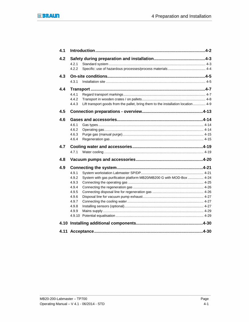
4 Preparation and Installation
MB20-200-Labmaster – TP700
Operating Manual – V 4.1 - 06/2014 - STD
Page
4-1
4.1 Introduction ...................................... ......................................................4-2
4.2 Safety during preparation and installation ........ ...................................4-3 4.2.1 Standard system .................................................................................................... 4-3 4.2.2 Specific: use of hazardous processes/process materials ....................................... 4-4
4.3 On-site conditions ................................ ..................................................4-5 4.3.1 Installation site ....................................................................................................... 4-5
4.4 Transport ......................................... .......................................................4-7 4.4.1 Regard transport markings ..................................................................................... 4-7 4.4.2 Transport in wooden crates / on pallets .................................................................. 4-8 4.4.3 Lift transport goods from the pallet, bring them to the installation location ............. 4-9
4.5 Connection preparations - overview ................ ................................... 4-13
4.6 Gases and accessories ............................. ........................................... 4-14 4.6.1 Gas types ............................................................................................................. 4-14 4.6.2 Operating gas ....................................................................................................... 4-14 4.6.3 Purge gas (manual purge) .................................................................................... 4-15 4.6.4 Regeneration gas ................................................................................................. 4-15
4.7 Cooling water and accessories ..................... ...................................... 4-19 4.7.1 Water cooling ....................................................................................................... 4-19
4.8 Vacuum pumps and accessories ...................... .................................. 4-20
4.9 Connecting the system ............................. ........................................... 4-21 4.9.1 System workstation Labmaster SP/DP ................................................................. 4-21 4.9.2 System with gas purification platform MB20/MB200 G with MOD-Box ................ 4-24 4.9.3 Connecting the operating gas .............................................................................. 4-25 4.9.4 Connecting the regeneration gas ......................................................................... 4-26 4.9.5 Connecting disposal line for regeneration gas ..................................................... 4-26 4.9.6 Disposal line for vacuum pump exhaust ............................................................... 4-27 4.9.7 Connecting the cooling water ............................................................................... 4-27 4.9.8 Installing sensors (optional) .................................................................................. 4-27 4.9.9 Mains supply ........................................................................................................ 4-29 4.9.10 Potential equalisation ........................................................................................... 4-29
4.10 Installing additional components................... ..................................... 4-30
4.11 Acceptance ........................................ ................................................... 4-30

4 Preparation and Installation
Introduction
Page
4-2
MB20-200-Labmaster – TP700
Operating Manual – V 4.1 – 06/2014 - STD
4 Preparation and Installation
4.1 Introduction
This chapter is intended for the operator and personnel responsible for the operation and service of the MBRAUN system.
The delivered MBRAUN system – including this operating manual – offers the technical and process-specific conditions for the safe operation of an inert gas system.
Prerequisite for the safety of the system is the proper preparation of the conditions on-site. The operator is responsible for making sure that the organisational prerequisites for the safe handling of the system are provided.
Follow especially the details in the safety and operator duties chapter and the on-site conditions (Chap. 4.2 and 4.4).
Preparing the on-site conditions
� Ambient conditions
� Floor conditions, carrying capacity
� Connections: mains and gas supply, coolant connections
Check hazard potential
► Check the process materials and processes used for their hazard potential (including their mutual reactions and final products).
► Follow the instructions in the safety chapter (Chap. 3).
► If necessary, set up additional equipment and functions
► If necessary, create a standard flow plan / standard operating procedure (SOP) for the specific conditions on-site:
Standard flow plan - standard operating procedure ( SOP)
► Specify the procedures according to your specific hazard and risk analysis:
� Regard the applicable data sheets and standards
� Agree on the procedures with your fire safety officer/radiation safety officer
� Always mark chemical containers and supply lines with the appropriate labels and warning labels.
� Use vacuum-resistant closed containers
� Use personal protective equipment (PPE): keep breathing protection full mask (with suitable filter), protective gloves and eye protection at the ready

4 Preparation and Installation
On-Site Conditions
MB20-200-Labmaster – TP700
Operating Manual – V 4.1 - 06/2014 - STD
Page
4-3
Training of the personnel / defining responsibiliti es
Train the personnel so that they can operate the system properly.
(See also Chap. 6.2).
Installation and commissioning
MBRAUN recommends having the installation and commissioning performed by MBRAUN trained personnel.
If you perform the installation and initial commissioning yourself:
► Follow the details for the installation and the instructions for commissioning in Chapter 6.
4.2 Safety during preparation and installation
NOTICE
Improper preparation of the installation of the system can cause damage to the system and additional risks.
► Follow the instructions for installation and commissioning (See Chap. 4 and 6).
► Installation and dismantling should only be performed by qualified trained personnel.
4.2.1 Standard system
The system has safety markings that should protect the operator against foreseeable dangers.
WARNING
Missing safety marking on the system causes preventable dangers!
► Always keep all safety markings on the system visible and legible
The accessories described in this chapter (gases, pressure regulators, etc.) are required for the connection of the system, but are not a component of the scope of delivery.
WARNING
Health and environmental hazards in case of incorrect handling of gases!
► The system must only be connected by trained personnel
► Attach a cut-off valve to the gas supply line

4 Preparation and Installation
Safety during preparation and installation
Page
4-4
MB20-200-Labmaster – TP700
Operating Manual – V 4.1 – 06/2014 - STD
The safe discharge of exhaust is the responsibility of the customer. MBRAUN assumes no liability for contamination of the surrounding atmosphere and any resulting health and environmental damage.
WARNING
Health and environmental hazards due to (contaminated) exhaust gas!
With the use of toxic or radioactive materials:
► Do not discharge gases into the environment.
► Connect the exhaust from the system to an in-house exhaust system.
4.2.2 Specific: use of hazardous processes/process materials
Additional system equipment
WARNING
System expansions and/or customer-specific processes/process materials/gases can cause specific hazards to health and the environment, depending on the degree of hazard of the materials used.
With the use of processes/process materials that present a hazard to health or the environment:
► Conduct a hazard analysis and if necessary a risk analysis
► If necessary, install additional safety equipment and functions
► Mark the system/system components with warning signs
► Connect the exhaust to an in-house exhaust system
► Ensure waste disposal according to valid national guidelines
► In case of questions, please contact MBRAUN Service
Preparation for the operation of a system with haza rdous processes/process materials
WARNING
Depending on the type and degree of hazard of the processes/process materials used, the operator of a system is subjected to a specific risk.
► Conduct a hazard analysis and if necessary a risk analysis
► Take measures for the safe handling of the processes/process materials according to your hazard or risk analysis
► Specify measures for behaviour in case of emergency (fire, escape or large quantities of inert gas, electrical failure)
► Summarize the measures if necessary in a standard operating procedure (SOP)/standard flow plan and hang it up where the operator can see it
► Train the operating personnel for behaviour in case of emergency

4 Preparation and Installation
On-Site Conditions
MB20-200-Labmaster – TP700
Operating Manual – V 4.1 - 06/2014 - STD
Page
4-5
4.3 On-site conditions
4.3.1 Installation site
The location for MBRAUN systems must be checked for the following on-site conditions.
Prerequisites:
Room Room temperature: +15°C and +30°C dry room climate
Good room ventilation
Area Floor level and even, no angles Carrying capacity: approx. 500 kg/m²
Distance Minimum distance to walls and objects 600 mm sufficient freedom to move in the work areas, e.g. glove areas, antechamber area and service areas
Room volume
The room volume must be significantly larger than the volume of the housing of the inert gas box.
If the system is a component of other systems, then the regulations and documentation for these systems with respect to the location must also be taken into consideration. In case of questions, please contact MBRAUN Service.
Securing of the installation location
For the case that the on-site conditions*) cannot be adhered to or the securing of specific devices in case of error is required,MBRAUN recommends safety measures such as, for example:
Exhaust system Monitoring of the function of the exhaust system and warning in case of disturbances/failure of the exhaust system
Oxygen content in the room air
Monitoring of the room air + O2 warning device: alarm in case of under running of a minimum oxygen concentration
Redundant gas supply shut-off
Safety kit for the redundant gas shut-off of the gas supply line (not included in standard scope of delivery; please contact MBRAUN Service).
Keep personal protective equipment (PPE) / oxygen masks ready
In front of the work room
In the work room
Personal O2 warning device
Supervision of the room and mark room with signs
In case of alarm, only enter the room with an oxygen mask

4 Preparation and Installation
On-site conditions
Page
4-6
MB20-200-Labmaster – TP700
Operating Manual – V 4.1 – 06/2014 - STD
In case of inert gas supply from compressed gas bot tles:
*) If the customer draws his inert gas supply from a compressed gas bottle (200 bar, 50 l = 10 Nm³), there is a risk only if the free room volume is smaller than 100 m³.
Free room volume
Free room volume > 100 m³
Already-used room volume
MBRAUN inert gas box
MBRAUN gas purifier
With installation of the system components in diffe rent locations:
If the gas purifier and inert gas box are installed in different locations, the instruction applies for both components of the system.
In case of questions, please contact MBRAUN Service.
Danger in case of failure to follow the on-site con ditions
DANGER
Risk of suffocation in case of failure to follow the on-site conditions!
Standard systems: when purging with operating gas or when opening inert gas-filled antechambers, inert gas escapes. This can cause a risk of suffocation!
Adhere to on-site conditions
► The remaining room volume must be significantly larger than the interior volume of the inert gas box.
► Set up the system in an area with good ventilation
► If possible, discharge exhaust via an exhaust gas discharge system!
If you cannot fulfil one or more of these conditions or if you would like advice about your specific on-site conditions:
► Please contact MBRAUN Service.

MB20-200-Labmaster – TP700
Operating Manual – V 4.1 - 06/2014 - STD
4.4 Transport
Before delivery and installation of an inert gas system, the customer receives the "Delivery and connection preparation" check list in order to be able to check all prerequisites for the transport and installation conditions.
Delivery of the system componwooden crate).
For subsequent transport on the customer's premises or within the building, take into account:
� The room for the installation of the system is prepared
� The transport paths (widfreely accessible
To be provided:
� Suitable transport vehicles vehicle
� Lift, wooden slats, tools
4.4.1 Regard transport markings
Gross weight specification
On the transport crate
4 Preparation and I
On-Site Conditions
STD
Before delivery and installation of an inert gas system, the customer receives the "Delivery and connection preparation" check list in order to be able to check all prerequisites for the transport and
Delivery of the system components takes place on pallets (woven in / pallets with planking or
For subsequent transport on the customer's premises or within the building, take into account:
The room for the installation of the system is prepared
The transport paths (width/radii of the floors, staircase, lift) are sufficiently dimensioned and
Suitable transport vehicles – depending on the type of delivery: crane, lift truck (pallet truck), lift
Lift, wooden slats, tools
ansport markings
Regard for transport and storage
Do not put weight on or stack transport goods
The centre of gravity of the transport goods is generally in the middle
If it is not in the middle, there is a marking on the transport crate
Optional for heavy load:
Specification of the attachment points
Gross weight specification Net weight, dimensions:
See delivery papers
Preparation and Installation
Site Conditions
Page
4-7
Before delivery and installation of an inert gas system, the customer receives the "Delivery and connection preparation" check list in order to be able to check all prerequisites for the transport and
ents takes place on pallets (woven in / pallets with planking or
For subsequent transport on the customer's premises or within the building, take into account:
th/radii of the floors, staircase, lift) are sufficiently dimensioned and
depending on the type of delivery: crane, lift truck (pallet truck), lift
Do not put weight on or stack transport goods
The centre of gravity of the transport goods is
If it is not in the middle, there is a marking on the
Specification of the attachment points

4 Preparation and Installation
Transport
Page
4-8
MB20-200-Labmaster – TP700
Operating Manual – V 4.1 – 06/2014 - STD
4.4.2 Transport in wooden crates / on pallets
Prerequisite
> Lift vehicle: minimum length: 2m
> Keep tools ready: nail puller, tin shears
Transport to the installation room
► Transport transport goods with lift vehicle
► Open the wooden crates with crowbar, nail puller
Loosen locks on the transport goods
WARNING Bands are under tension! They can fly off when cutting and cause facial injuries!
► Wear goggles
► Stand to the side of the tension direction
► Cut tension bands slowly (tin shears)
► Remove plastic film
! The rest of the transport depends on the type of system delivered.

4 Preparation and Installation
On-Site Conditions
MB20-200-Labmaster – TP700
Operating Manual – V 4.1 - 06/2014 - STD
Page
4-9
4.4.3 Lift transport goods from the pallet, bring them to the installation location
WARNING
Risk of tipping! Risk of injury!
► Regard the position of the centre of gravity! of the transport goods!
4.4.3.1 Transport of a box + antechamber (without gas purifier)
! For boxes with antechambers, the lifting point is nearly in the middle, however slightly offset in the direction of the antechamber.
� For systems with antechamber: Pick-up point in the middle below the box, slightly offset
� For systems with higher centre of gravity: Regard the marking on the system. (If there is no marking: pick-up point in the middle below the box)
NOTICE
► Damage to the box/the frame from the forks of the lift vehicle (pallet truck)!
► Protect the edges of the box with wooden bar, as described below
Preventing damage to the frame
► Place a wooden bar on the forks of the lift vehicle
► Move the carriers of the fork lift up until they are a little below the box
► Align wooden bars so that they fall in line with the protruding screws
→ The system is ready for transport
Transporting the system:
► Start up lift vehicle
► Bring transport goods to the intended location
WARNING Risk of damage and injury due to tipping/rolling load! Regard the following instructions when setting down the transport goods!

4 Preparation and Installation
Transport
Page
4-10
MB20-200-Labmaster – TP700
Operating Manual – V 4.1 – 06/2014 - STD
Lowering from the pallet
► Approach with the lift vehicle below the frame - a bit offset from the middle in the direction of the antechamber.
WARNING Property damage + risk of injury due to tipping/rolling load! Regard the following instructions when setting down the transport goods! Regard the following instructions when setting down the transport goods!
Setting down the transport goods
Before setting down the transport goods:
► Make sure that the weight is set evenly on the max. moved-out plate feet
► Screw in the plate feet only afterwards
► Move system on rollers slowly to its final location
► Align system
► Screw plate feet out far enough that the rollers are no longer in contact with the floor
→ This way, the system stands firmly on the floor.
4.4.3.2 Transport of a system with an integrated gas purifier
Example: Labmaster / MOD box:
Lift angles
► Screw 2 mounting lift angles on each of 4 corners/fastening points of a MOD-box
► Approach with lift
► Use transport crane
CAUTION Property damage + risk of injury due to tipping/rolling load! Regard the following instructions when setting down the transport goods! Regard the instructions above when setting down the transport goods!
Ring screw
Optional for heavy loads
► Attach lift on pre-mounted ring screws

4 Preparation and Installation
On-Site Conditions
MB20-200-Labmaster – TP700
Operating Manual – V 4.1 - 06/2014 - STD
Page
4-11
4.4.3.3 Transport of a gas purifier with crane
Gas purifying system
► Sling lift around the 4 corners of the gas purifier
WARNING
Damage and electrical hazard!
The cable duct runs under the housing of the gas purifier (marked in red).
With improper transport, the cable duct may be damaged! This can cause damage to the cable duct and electrical hazards!
► Transport the system properly
Do not tip!
► Fasten lift on the crane
► Lift the crane hook carefully
► Check whether the gas purifier sits well in the sling
► Only then lift from the pallet
► and bring to the installation location
► Even setting down of the transport goods on the four rollers (if no plate feet).
► Install and align system

4 Preparation and Installation
Transport
Page
4-12
MB20-200-Labmaster – TP700
Operating Manual – V 4.1 – 06/2014 - STD
4.4.3.4 Transport at a later time
When transporting at a later time, also consider:
� Use wooden transport crates
� Transport on pallets
� Stabilise the transport goods against slipping with profiled timbers, aligning the rollers
� Secure loose parts (such as touch panel, antechamber tray) with bubble wrap
� Pack in film
� Transport in air-suspended truck required
(Follow the check-list "Preparation for delivery and connection" from MBRAUN)

4 Preparation and Installation
On-Site Conditions
MB20-200-Labmaster – TP700
Operating Manual – V 4.1 - 06/2014 - STD
Page
4-13
4.5 Connection preparations - overview
Before delivery, the user receives an information sheet about the required connection accessories for his system. The following details provide a general overview.
Gas purifier INPUT (� source for the gas purifier) OUTPUT � for disposal equipment)
Input pressure – from source
Pressure / temp. Connection Connection Pressure Exhaust
Operating gas / control gas
≤ 200 bar /≤ 20 MPa
5.5 – 6.0 bar /0.55 – 0.6 MPa
10 mm from gas purifier + vacuum pump
KF 40 /ø 44.5 mm
Pressureless max < 0 mbar to min - 2mbar
Regeneration gas ≤ 200 bar /≤ 20 MPa
0.3 – 0.4 bar /30 – 40 kPa
10 mm
Cooling water 2.0 bar / 0.2 MPa
max. 10°C – 15° C
10 mm pressureless
Box KF40
Purge gas (inertisation of the box from ext. source)
≤ 200 bar /≤ 20 MPa
5.5 – 6.0 bar /0.55 – 0.6 MPa
10 mm KF 40 /ø 44.5 mm
pressureless

4 Preparation and Installation
Gases and accessories
Page
4-14
MB20-200-Labmaster – TP700
Operating Manual – V 4.1 – 06/2014 - STD
4.6 Gases and accessories
4.6.1 Gas types
In standard systems, nitrogen, argon or helium can be used as gas types. For regeneration gas, MBRAUN recommends always using the same gas type as the operating and purge gas. If argon is the operating gas, then argon should be used as purge gas and an argon/hydrogen mixture should be used as regeneration gas.
! Gas type: in general, only the gases named above may be used.
Other gas mixtures - including those with carbon dioxide and hydrogen - are possible. However, this requires special system preparations by MBRAUN , which are not a component of a standard system.
WARNING
Exceeding the concentration of hydrogen in the regeneration gas of > 10% is not permitted!.
Heed the safety instructions in the chapter safety, hazards when handling gases.
4.6.2 Operating gas
Operating gas Type / mass Use
Gas type Nitrogen, Argon or Helium � Construction and maintenance of the pure gas atmosphere: pressure regulation and purging of the box
� Valve control: pressure gas of electropneumatic valves and pneumatic controller
Purity Medium purity from bottles or other supply equipment (recommended: 4.8 or better)
Quantity Constant supply for operation of the system
Accessories
Gas regulator Pressure regulation of the operating gas
Pressure 200 bar (20 MPa) primary, 5.5-6.0 bar (0.55 – 0.6 MPa) secondary
Flow Flow rate 250 l/min
Connection 3/8” hose barb
Supply line Connection of the gas source with the system connection operating gas IN
Material 3/8” i.d fabric reinforced hose
Connection 3/8” hose barb
Length Optional (length as required):

4 Preparation and Installation
On-Site Conditions
MB20-200-Labmaster – TP700
Operating Manual – V 4.1 - 06/2014 - STD
Page
4-15
4.6.3 Purge gas (manual purge)
Purge Gas Type Use
Gas type Like operating gas (see above) Manual purge*) to inertise the box on (re) commissioning, intermediate purging; pressure regulation for purge gas
Purity Medium purity from bottles or other supply equipment (recommended: 4.8 or better)
Quantity Approx. 10 - 12 m3 each m3 box volume
Accessories
Gas regulator Pressure regulation for purge gas with manual purge
Pressure 200 bar (20 MPa) primary, 5.5-6.0 bar (0.55 – 0.6 MPa) secondary
Flow 250 l/min
Connection 3/8” hose barb
Supply line for purge gas:
Line from the purge gas source to the inert gas box (purge gas IN)
Connection 3/8” hose barb
Disposal line for purge gas exhaust:
Connection Purge gas OFF with the user's supply equipment (pressureless)
Connection Extension with Ø 42 mm corrugated hose, length 100 mm and 2 hose clamps possible.
Connect hose for the purge gas exhaust directly to the disposal equipment
"QuickPurge" automatic purge
Automatic purge Type Use
Purge gas connection Like operating gas connection (see above)
For quick inertisation of large-volume boxes
No connection accessories required
Disposal line for purge gas exhaust:
Connect hose for the purge gas exhaust directly to the disposal equipment
4.6.4 Regeneration gas
! Gas type regeneration RKM
MBRAUN recommends always using the same carrier gases as for the operating gas: �

4 Preparation and Installation
Gases and accessories
Page
4-16
MB20-200-Labmaster – TP700
Operating Manual – V 4.1 – 06/2014 - STD
see table below
Regeneration gas RKM
Type / mass Use
Gas type Depending on the type of working and purge gas used:
Reprocessing of saturated H2O/O2 purification units
WARNING
Never use hydrogen mixture with H2 percentage > 10%!
Nitrogen is operating gas:
� Nitrogen/hydrogen mixture (90-95% N2 with 3-10% H2)
Argon is operating gas:
� Argon/hydrogen mixture (90-95% Ar2 with 3-10% H2)
Helium is operating gas:
� Helium/hydrogen mixture (90-95% He with 3-10% H2)
Purity Medium purity from bottles or other supply equipment (recommended: 4.8 or better)
Quantity Approx. 3.5 m3 per regeneration
Regeneration gas accessories
Type / mass Use
Gas regulator Pressure regulation of the regeneration gas
Pressure 200 bar (20 MPa) primary, 0.3-0.4 bar (30 – 40 kPa) secondary
Flow Flow rate approx. 1.25 m³/h (10-20 l/min)
Connection 3/8” hose barb
Supply line Connection of the gas source with the system connection Regeneration gas IN
Material 3/8” i.d. fabric reinforced hose
Connection 3/8” hose barb
Cont. see next page
Regeneration gas accessories
Type / mass Use
Disposal line Connection Regeneration gas OUTwith the user's disposal equipment (pressureless)
NOTE
Material 3/8” mm fabric reinforced hose
optional

MB20-200-Labmaster – TP700
Operating Manual – V 4.1 - 06/2014 - STD
Connection 3/8” hose barb
4.6.4.1 Specifics of regenerable
Regeneration gas LMF
Type / mass
Gas type Only use pure inert gas operating
Accessories regeneration gas LMF
In-house disposal equipment Explosion protection required!
Disposal line
Material 3/8” mm fabric reinforced hose
Connection 3/8” hose barb
Equipment with solvent filter (LMF) + box purging:
Solvent filter (LMF) + box purging:
Regardfleece
Connect connecting adapters exhaust air hose to pressureless exhaust air
4 Preparation and Installation
On-Site Conditions
STD
See particularities exhaust of a regenerable LMF!
3/8” hose barb
regenerable LMF (optional)
Type / mass Use
Only use pure inert gas – like operating gas
Reprocessing of saturated solvent filter purification units
WARNING
Do not use a hydrogen mixture!
WARNING
Explosion protection required!
Safe disposal of regeneration exhaust LMF
Regeneration gas OUTregeneration gas exhaust
3/8” mm fabric reinforced hose
3/8” hose barb
Equipment with solvent filter (LMF) + box purging:
Solvent filter (LMF) + box purging:
Regard after installation/maintenance: check correct fit of the protective fleece
Connect connecting adapters exhaust air hose to pressureless exhaust air
Preparation and Installation
Site Conditions
Page
4-17
cularities exhaust of LMF!
Reprocessing of saturated - solvent filter purification units
Do not use a hydrogen mixture!
Safe disposal of regeneration
Regeneration gas OUT for regeneration gas exhaust
after installation/maintenance: check correct fit of the protective
Connect connecting adapters exhaust air hose to pressureless exhaust air

4 Preparation and Installation
Gases and accessories
Page
4-18
MB20-200-Labmaster – TP700
Operating Manual – V 4.1 – 06/2014 - STD
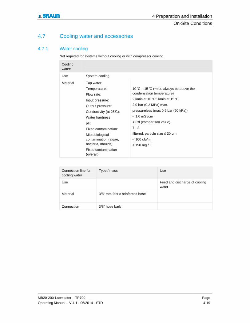
4 Preparation and Installation
On-Site Conditions
MB20-200-Labmaster – TP700
Operating Manual – V 4.1 - 06/2014 - STD
Page
4-19
4.7 Cooling water and accessories
4.7.1 Water cooling
Not required for systems without cooling or with compressor cooling.
Cooling water:
Use System cooling
Material Tap water:
Temperature:
Flow rate:
Input pressure:
Output pressure:
Conductivity (at 25°C):
Water hardness
pH:
Fixed contamination:
Microbiological contamination (algae, bacteria, moulds):
Fixed contamination (overall):
10 °C – 15 °C (*mus always be above the condensation temperature)
2 l/min at 10 °C5 l/min at 15 °C
2.0 bar (0.2 MPa) max.
pressureless (max 0.5 bar (50 kPa))
< 1.0 mS /cm
< 8°d (comparison value)
7 - 8
filtered, particle size ≤ 30 µm
< 100 cfu/ml
≤ 150 mg / l
Connection line for cooling water
Type / mass Use
Use Feed and discharge of cooling water
Material 3/8” mm fabric reinforced hose
Connection 3/8” hose barb

4 Preparation and Installation
Vacuum pumps and accessories
Page
4-20
MB20-200-Labmaster – TP700
Operating Manual – V 4.1 – 06/2014 - STD
4.8 Vacuum pumps and accessories
Vacuum pump gas purifier (VPG)
Type / mass Use
Disposal line
Material
Ø 25 mm fabric-reinforced hose and Ø 25 mm hose connector or Ø 25 mm stainless steel pipe with flange and clamp
Optional (length as required):
Connection of the vacuum pump exhaust (oil mist and exhaust) with the user's disposal equipment (pressureless)
Separate vacuum pump antechamber VP1..2
as previously Optional, for high quality requirements of box and/or antechamber atmosphere
Separate vacuum pump VPGL
For use of solvents as process material:
Disposal line
Material
as previously Connection of the vacuum pump exhaust (oil mist and exhaust) with the user's disposal equipment (pressureless)
4.8.1.1 Particularities: purging of the pump (optional)
Vacuum pump accessories
Type / mass Use
Purge kit Purge kit with air filter for scroll pumps
Purging of the vacuum pump if contaminated/aggressive gases escape from the antechamber into the vacuum pump

4 Preparation and Installation
On-Site Conditions
MB20-200-Labmaster – TP700
Operating Manual – V 4.1 - 06/2014 - STD
Page
4-21
4.9 Connecting the system
Prerequisites
> The media connections are available
> Correct connections are available
> Use pressure reducing valves (not included in the scope of delivery of standard systems)
4.9.1 System workstation Labmaster SP/DP
Optional: with box cooling + refrigerator + LMF (absorption p rinciple)
Labmaster SP
Front view

4 Preparation and Installation
Connecting the system
Page
4-22
MB20-200-Labmaster – TP700
Operating Manual – V 4.1 – 06/2014 - STD
System with LMF + RKI
► Connecting the system:
(1) Mount the operating console and make connections to the control cabinet
(2) Insert sensors: note that the measurement cells are installed in the middle of the gas line
(3) Connect antechamber to vacuum pump
(4) Gas input antechamber refill
(5) Fill necks active carbon for LMF (Option – see below)
(6) Media connections (see detail)
(7) Optional: exhaust of the vacuum pump to exhaust air system
(8) see following page: detail of box cooling / refrigerator
Detail: media connections
(1) Electrical mains connection
(2) Mains connection vacuum pump
(3) Condensate return
(4) Operating gas input
(5) Regeneration gas input
(6) Cooling water input
(7) Cooling water output
Connection of earthing bolts (next to the bar for media connections)
! Follow the marking on your system! The assignment of the connections may differ according to the customer.
1 2 3 4 5 6 7
3 4
5
7
3 6
1
2 8

4 Preparation and Installation
On-Site Conditions
MB20-200-Labmaster – TP700
Operating Manual – V 4.1 - 06/2014 - STD
Page
4-23
Optional: System box cooling and/or refrigerator/freezer
(1) Box cooling RKI (see separate manual)
(2) Refrigerator/freezer
1
2

4 Preparation and Installation
Connecting the system
Page
4-24
MB20-200-Labmaster – TP700
Operating Manual – V 4.1 – 06/2014 - STD
4.9.2 System with gas purification platform MB20/MB200 G with MOD-Box
► Installation of accessories
(1) Mount separately packaged operating console
(2) Insert sensors: make sure that the measurement cells are installed in the middle of the gas line - lay cables from the GR unit in the cable ducts - connect colour of the cable + sensors so they match + plug in RJ45 connector
(3) optional: customer-specific feedthroughs
► Connect box and gas purifier (GR):
if necessary, connect with corrugated hoses/stainless steel pipe:
(1) a) Output GR + b) Input box (circulation)
(2) a) Output Box +b) Input GR (circulation)
(3) a) Antechamber +b) Vacuum pump
(4) Input antechamber refill (here: from GR)
(5) Media connections (see below for details
(6) Connect exhaust vacuum pump if necessary to the in-house exhaust line
optional:customer-specific connections
3
1
2
3b
1b 1a 2a 2b
3a
6
5
4
6

4 Preparation and Installation
On-Site Conditions
MB20-200-Labmaster – TP700
Operating Manual – V 4.1 - 06/2014 - STD
Page
4-25
Detail – Standard system
► Connecting media
(1) Operating gas input
(2) Main electrical connection
(3) Regeneration gas input
(4) Earthing bolts
(5) Cooling water output
(6) Vacuum connection
(7) Cooling water input
(8) Mains connection vacuum pump
(9) Regeneration output (on exhaust air)
! Follow the marking on your system! The assignment of the connections may differ according to the customer.
4.9.3 Connecting the operating gas
► Connect pressure reducing valve to operating gas source (heed manufacturer's connection instructions).
► Connect supply line between gas source and system connection Operating gas IN. (the precise input pressure is specified on the system connection "Operating gas IN")
► Set pressure reducing valve to this value
► Open pressure reducing valve.
! In standard systems:
One connection: operating gas simultaneously takes over the function of the control gas
In modular systems:
Separate connections for operating gas and control gas

4 Preparation and Installation
Connecting the system
Page
4-26
MB20-200-Labmaster – TP700
Operating Manual – V 4.1 – 06/2014 - STD
4.9.4 Connecting the regeneration gas
► Connect pressure reducing valve to regeneration gas source (heed manufacturer's connection instructions).
► Connect supply line between gas source and system connection Regeneration gas IN . (the precise input pressure is specified on the system connection "Regeneration gas IN")
► Set pressure reducing valve to this value and
► Open pressure reducing valve.
4.9.5 Connecting disposal line for regeneration gas
DANGER
Risk of personal injury and environmental damage in case of escape of used regeneration gas!
► Regard the information of the gas supplier about adverse health and environmental effects
► Discharge used regeneration gas via an exhaust disposal system which is designed for the degree of hazard of the process materials used
In case radioactive or toxic materials are used, do not discharge gas into the environment!
See also Chap. 3. 2 Proper use
► Establish disposal line between system connection Regeneration gas OUT and disposal equipment.
→ Connection is pressureless

4 Preparation and Installation
On-Site Conditions
MB20-200-Labmaster – TP700
Operating Manual – V 4.1 - 06/2014 - STD
Page
4-27
4.9.6 Disposal line for vacuum pump exhaust
► Establish disposal line between exhaust output of the vacuum pump and the disposal equipment (heed vacuum pump manufacturer's operating manual)
→ The connection is pressureless
! Depending on the location of the system and the vacuum pump, an exhaust filter can be used instead of a disposal line.
In case of questions, please contact MBRAUN Service.
4.9.7 Connecting the cooling water
Not required for systems without cooling or with compressor cooling.
► Establish system connection Cooling water IN to cooling water source.
► Establish system connection Cooling water OUT to disposal equipment. The connection must be pressureless (max. return pressure: 0.5 bar (50 kPa).
► Open cooling water (the required flow quantity depends on the water temperature)
! Systems with additional or specially-cooled components may require a separate coolant supply.
4.9.8 Installing sensors (optional)
See also Chap. System description as well as Technical Data for measurement devices in the annex.
The sensors are inserted in the pipework (at the box output).
Integration of the sensors into an inert gas system (excerpt)
Control is handled by the PLC.
Display of the measurement values H2O and O2 takes place on the touch panel

4 Preparation and Installation
Connecting the system
Page
4-28
MB20-200-Labmaster – TP700
Operating Manual – V 4.1 – 06/2014 - STD
4.9.8.1 Oxygen sensor MB-OX-SE1
Connection
The oxygen measurement device is connected using a RJ45 connector (8-pin).
Installation
! Before applying the supply voltage, the sensor should be subjected to the inert gas for at least 1 minute.
The oxygen sensor is fastened with a vacuum-tight NW40 flange using centring ring and clamp.
! The sensor may only be connected to the PLC controller if the complete system is sufficiently purged with inert gas, see Chapter "Inert gas box, inertising the box).
4.9.8.2 Moisture measurement device MB MO-SE-1
Connection
► Connect the moisture measurement device using a RJ45 connector (8-pin).
Installation
! Before applying the supply voltage, the sensor should be subjected to the inert gas for at least 1 minute.
► Fasten the moisture measurement device with a vacuum-tight NW40 flange using centring ring and clamp.
! The sensor should only be put into operation after sufficient purging of the box:
that is, with an O2 concentration < 100 ppm.

4 Preparation and Installation
On-Site Conditions
MB20-200-Labmaster – TP700
Operating Manual – V 4.1 - 06/2014 - STD
Page
4-29
4.9.9 Mains supply
DANGER
Risk of personal injury due to electrical voltage in case of error: uncontrolled muscle reactions, crippling, burns or death can result!
► All work on the mains connection and the electrical system may only performed by a trained electrician.
1. Standard systems:
► Connect to current source: with mains plug (Schuko plug or country-specific)
2. Special systems:
► Connect the open mains connection line to a fused and earthed current source. Connection values: see type plate and wiring diagram (see Chap. 13)
4.9.10 Potential equalisation
Due to increased leakage current( EMC filter current), an additional potential equalisation according to EN 60204-1 is required.
M8 bolts on the rear side of the gas purifier (see above):
► Connect green-yellow cable with 10 mm² Cu to the local potential equalisation
Follow the instruction on the system (below the main switch)

4 Preparation and Installation
Installing additional components
Page
4-30
MB20-200-Labmaster – TP700
Operating Manual – V 4.1 – 06/2014 - STD
4.10 Installing additional components
Follow the descriptions in the optional additional chapters (7-10 A..X).
4.11 Acceptance
The acceptance test will be performed by MBRAUN service technicians if the installation and commissioning were done by MBRAUN .
In case of installation and initial commissioning by the customer, an acceptance test and functional inspection must be conducted before operating the system.
! Customer's responsibility:
For delivery of a system that will be integrated into a customer's system or into which additional customer components will be integrated, the customer guarantees compliance with the machine directive 2006/42/EC.

5 Controller
MB20-200-Labmaster – TP700
Operating Manual – V 4.1 - 06/2014 - STD
Page
5-1
5.1 Introduction ............................................................................................5-2
5.2 Safety ......................................................................................................5-2
5.3 Touch panel with screens and buttons ................................................5-3 5.3.1 Start screen ............................................................................................................ 5-3 5.3.2 Navigation .............................................................................................................. 5-5 5.3.3 System components screens ................................................................................. 5-6 5.3.4 Functions screen .................................................................................................... 5-8 5.3.5 Parameters screen ............................................................................................... 5-10 5.3.6 Trend panel screen .............................................................................................. 5-12 5.3.7 Warnings and error messages panel screen ........................................................ 5-13
5.4 Service .................................................................................................. 5-13 5.4.1 Monitoring and testing .......................................................................................... 5-14 5.4.2 System information............................................................................................... 5-15
5.5 Pre-set parameters ............................................................................... 5-21
5.6 Overview ............................................................................................... 5-24 5.6.1 Navigation from the start screen (System components und functions)................. 5-24 5.6.2 Menu screen selection ......................................................................................... 5-25 5.6.3 Components screen ............................................................................................. 5-26 5.6.4 Service screen selection ...................................................................................... 5-30

5 Controller
Introduction
Page
5-2
MB20-200-Labmaster – TP700
Operating Manual – V 4.1 - 06/2014 - STD
5 Controller
5.1 Introduction
This chapter will present the basic principles of the controller:
� Structure and function of the touch panel with screens
� Navigation between the individual screens of the system and of the components
� The display of process data (measurement values, status processes)
Controller architecture:
Basic principle
TP touch panel
SPS / PLC controller
5.2 Safety
The controller of the standard systems is designed for normal operation with non-dangerous processes/process materials. Some of the parameters that are pre-set can be adapted to customer-specific conditions in the course of the minimum/maximum values (cf. Pre-set parameters in Chap. 5.6).
Parameterisation may only be done by qualified personnel.
As an additional option, a password concept with various access authorisations can be set up (not included in the standard scope of delivery).
If there are increased safety requirements for your applications that require controller-technical additional functions:
► Please contact MBRAUN Service.

5 Controller
Touch panel with screens and buttons
MB20-200-Labmaster – TP700
Operating Manual – V 4.1 - 06/2014 - STD
Page
5-3
5.3 Touch panel with screens and buttons
By default, MBRAUN systems are equipped with a PLC and a touch panel. The touch panel is the central operating and display unit of the system. It is in a central, easy-to-see position.
After it is switched on, the system boots up automatically. After a brief wait, the start indicator appears.
The start indicator maps the configuration of the system with the main components and serves as the operating interface. It looks different depending on how the system is equipped.
5.3.1 Start screen
Start screen 01102-1
Structure
(1) Navigation bar
(2) Operator panel with
� Indicators (a) and (b)
� Symbol buttons / buttons (c) and (d))
Structure of start screen
(1) Navigation bar
� Navigation to functions and menu
� Alarms: display of alarm at issue and navigation to warning list (see 5.3.6)
(2) Operator panel
The operator panel contains status indicators and buttons with navigation functions (see following section for explanation).
In the example: gas purifier with 2 purifiers (RKM) and solvent filter (LMF) with 2 filters and separate vacuum pump (VPGL)

5 Controller
Touch panel with screens and buttons
Page
5-4
MB20-200-Labmaster – TP700
Operating Manual – V 4.1 - 06/2014 - STD
5.3.1.1 Symbol buttons of the system components
The system components are shown as symbols on the start screen. The symbols indicate the status of a component; sometimes they are buttons with navigation functions.
Symbol for the box � Display values box pressure + box atmosphere (residual content H2O and O2)
� Display values temperature freezer / box (optional)
� Touch the symbol button: � call up the "Box parameters" screen
Symbol for the antechamber
� Display values box pressure + box atmosphere (residual content H2O and O2)
� Display values temperature freezer / box (optional)
� Touch the symbol button: � call up the "Box parameters" screen
Symbol for the reactor (removal of H2O / O2) Ex. equipped with:
� Touch the symbol button: � call up the "Gas purifier" screen
VPG: Vacuum pump � Status indicator
RKM: Reactor Standard: 1 RKM / optional: 2 RKM
� Status indicator
Blower (GB) � Status indicator
Symbol for the solvent filter unit
(optional) Ex. equipped with:
� Touch the symbol button: � call up the "Solvent filter" screen
� Vacuum pump (VPGL) (optional)
� Status indicator (separate vacuum pump for the solvent filter)
� Gas purifier solvent (LMF)optional: 1 or 2 LMF
Touch the button:� call up the "Solvent filter" screen

5 Controller
Touch panel with screens and buttons
MB20-200-Labmaster – TP700
Operating Manual – V 4.1 - 06/2014 - STD
Page
5-5
5.3.2 Navigation
Navigation to the various screens of the touch panel can be accomplished
� Symbol buttons (see above)
� Navigation bar buttons
� Buttons on the "Menu Screen Selection" screen
5.3.2.1 Navigation bar buttons
The bar with the navigation buttons is on the left side of the touch panel. These differ depending on the screen.
Touch the button:
Back to the previous screen
Touch the button:
Back to the start screen
ALARM button red: error in operation, system error or component failure Status: see 5.3.6
5.3.2.2 Navigation using the Menu Screen Selection
With the "Screen Selection" screen type, subordinate screens are called up:
� Menu Screen Selection (example)
� Service screen selection menu (see Chap. 5.4)
Menu Screen Selection 01120
Structure
(1) Navigation bar
(2) Navigation buttons:
Navigating:
Touch the buttons, to call the corresponding screens
! The buttons will vary depending on how the system is equipped.

5 Controller
Touch panel with screens and buttons
Page
5-6
MB20-200-Labmaster – TP700
Operating Manual – V 4.1 - 06/2014 - STD
5.3.3 System components screens
The screens for the components of the system gas purifier and antechamber are structured according to the following principle:
Purification Unit screen 01310-2
Example
(1) Bar with navigation buttons
(2) Scheme of the system components
(3) Permanent display: measurement values
(4) Operator panel with function buttons
! For more information, consult:
� the overview of the panel screens and their activation (Chap. 5.7).
� Details for operation of the individual system components in the respective chapters (7, 8, 9 and 10 (optional))
� The system component "box" is operated using the "Menu Screen Selection" (for details see Chap. 8).
Status indicators RKM / LMF
Status indication of the symbols:
The graphic symbol buttons indicate the respective functional status by their colour:
Status of the gas purifier (RKM):
OFF / WHITE Not active
ON / GREEN Purification function active - in circulation operation
RED / MAGENTA Regeneration of the reactor
RED / MAGENTA Regeneration / heating up

5 Controller
Touch panel with screens and buttons
MB20-200-Labmaster – TP700
Operating Manual – V 4.1 - 06/2014 - STD
Page
5-7
Status indicators: designations of valves
GREEN Valve open
WHITE Valve closed
RED Failure of the valve / error
YELLOW Abnormal state *)
Status indicators: vacuum pump / analog: blower
GREEN switched ON
WHITE switched OFF
RED Failure / error
YELLOW Abnormal state *)
*) Explanation of "non-normal state":
YELLOW Example "Non-normal state of blower":
Symbol displayed in yellow: if, for example, a function is switched on but not yet active, because prerequisites are not yet fulfilled:Example: system with 2-filter LMF: circulation RKM is switched on – however the blower is not yet running since no LMF filter was switched into circulation.

5 Controller
Touch panel with screens and buttons
Page
5-8
MB20-200-Labmaster – TP700
Operating Manual – V 4.1 - 06/2014 - STD
5.3.4 Functions screen
Quick operation:
The "Functions" panel screen (1, 2..) offers direct access to the function buttons without detouring to the component screens.
Functions screen 1 01160-1
Structure
(1) Navigation: additional functions : call Function screen 2
(2) Activate/deactivate functions using buttons
Functions screen 2 01161
Example
Functions 2 with additional components (optional)
! Only function buttons are depicted whose associated components are also actually present in the system.
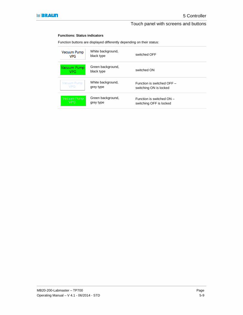
5 Controller
Touch panel with screens and buttons
MB20-200-Labmaster – TP700
Operating Manual – V 4.1 - 06/2014 - STD
Page
5-9
Functions: Status indicators
Function buttons are displayed differently depending on their status:
White background, black type switched OFF
Green background, black type switched ON
White background, grey type
Function is switched OFF – switching ON is locked
Green background, grey type
Function is switched ON – switching OFF is locked
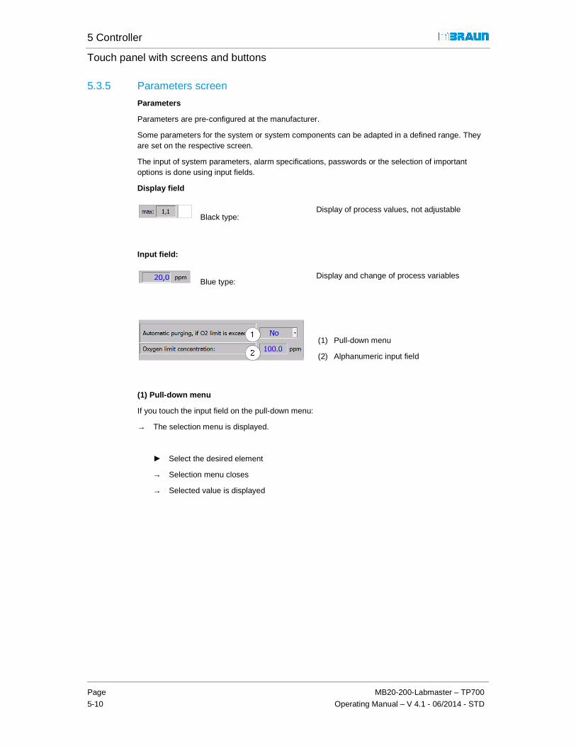
5 Controller
Touch panel with screens and buttons
Page
5-10
MB20-200-Labmaster – TP700
Operating Manual – V 4.1 - 06/2014 - STD
5.3.5 Parameters screen
Parameters
Parameters are pre-configured at the manufacturer.
Some parameters for the system or system components can be adapted in a defined range. They are set on the respective screen.
The input of system parameters, alarm specifications, passwords or the selection of important options is done using input fields.
Display field
Black type: Display of process values, not adjustable
Input field:
Blue type: Display and change of process variables
(1) Pull-down menu
(2) Alphanumeric input field
(1) Pull-down menu
If you touch the input field on the pull-down menu:
→ The selection menu is displayed.
► Select the desired element
→ Selection menu closes
→ Selected value is displayed
5 Controller
Touch panel with screens and buttons
MB20-200-Labmaster – TP700
Operating Manual – V 4.1 - 06/2014 - STD
Page
5-11
(2) Alphanumeric input field
If you touch the alphanumeric input field:
→ Button field opens
(1) Min / Max of allowed parameter range
(2) Input field: display of input value
(3) Input buttons
(4) Enter button
► Input by touching the input buttons
► Confirm with Enter button
→ Button field closes
→ New input value appears in input field.

5 Controller
Touch panel with screens and buttons
Page
5-12
MB20-200-Labmaster – TP700
Operating Manual – V 4.1 - 06/2014 - STD
5.3.6 Trend panel screen
Trend curves indicate the temporal course of process values:
� Box trend curves: (H2O, O2 and box pressure) (display of other values optional)
� Antechamber trend curve: pressure
Antechamber trend curve screen 01602
Example:
The time axis of the diagram runs from right to left:
The current values are displayed on the left side.
X - axis = time scale – division into hours and minutes Y- axis = measurement values of physical units (here: pressure in mbar)
Shift time axis
Stretch or compress time axis
Return to the current time

MB20-200-Labmaster – TP700
Operating Manual – V 4.1 - 06/2014 - STD
5.3.7 Warnings and error messages panel screen
The "Alarm" button is displayed on all system and function screens on the navigation bar. The status of the button indicates function error (system error or component failure) :
Status:
Static
Flashing
Static
See Chap. 11.1
5.4 Service
Using the "Service" screen, the functions for monitoring and checking of system components and system information are called
Service: Screen Selection
(1) Monitoring + Test: - hours of operation - H2O sensor - box-pressure-sensor- pressure control valve
(2) System information: - OS services (password, calibrate screens, etc.)- Info -Service MBRAUN (only accessible to
Touch panel with screens and buttons
STD
Warnings and error messages panel screen
The "Alarm" button is displayed on all system and function screens on the navigation bar. The status of the button indicates function error (system error or component failure) :
No message present
Flashing One or more messages present, one or more messages not acknowledged
One or more messages present, all messages acknowledged
Using the "Service" screen, the functions for monitoring and checking of system components and system information are called up.
Service: Screen Selection 01700
Navigation (optional) to
(1) Monitoring + Test
(2) System Information
Navigation:
Buttons call the corresponding screens:
sensor pressure control valve
OS services (password, calibrate screens, etc.)
(only accessible to MBRAUN Service)
5 Controller
Touch panel with screens and buttons
Page
5-13
The "Alarm" button is displayed on all system and function screens on the navigation bar. The
one or more messages not
One or more messages present, all messages acknowledged
Using the "Service" screen, the functions for monitoring and checking of system components and
Navigation (optional) to
Monitoring + Test
System Information
call the corresponding

5 Controller
Service
Page
5-14
MB20-200-Labmaster – TP700
Operating Manual – V 4.1 - 06/2014 - STD
5.4.1 Monitoring and testing
5.4.1.1 Service Operating Hours (electric drives)
Using the display of the operating hours of an electrical drive, inspection and maintenance cycles can be determined and monitored.
Service: Operating Hours 01703
Electrical drives:
Display of operating hours for
� Vacuum pumps
� Blower
� Compressor box cooling
� Compressor freezer
5.4.1.2 Service: H2O sensor
The regular maintenance of the sensor is monitored with the "Service Moisture Analyzer" screen. A warning is triggered after 2000 hours of operation.
Service Moisture Analyzer 01705
Cleaning the H2O sensor:
See Chap. 12 Inspection and maintenance
After cleaning the H2O sensor:
► Reset the hours of operation to zero with the Reset button (1)

5 Controller
Touch panel with screens and buttons
MB20-200-Labmaster – TP700
Operating Manual – V 4.1 - 06/2014 - STD
Page
5-15
5.4.1.3 Service: cyclical check of the pressure control valve
Optional: cyclical check of the box pressure control valve (MB-OSV)
Service: cyclical check of the pressure control valve 01706-1
See Chap. 12 Inspection and maintenance
5.4.2 System information
5.4.2.1 OS Services
Operation System – services (OS services) 01702
Date + Time
Date and time
Is pre-set by the manufacturer to Eastern Time (US)
Note:
If in a region where daylight savings time (DST) is observed, this change must be made manually.
5 Controller
Service
Page
5-16
MB20-200-Labmaster – TP700
Operating Manual – V 4.1 - 06/2014 - STD

5 Controller
Touch panel with screens and buttons
MB20-200-Labmaster – TP700
Operating Manual – V 4.1 - 06/2014 - STD
Page
5-17
Settings on the touch panel
! Protection of the surface of the touch panel:
A plastic stylus should be used for navigation and settings on the touch panel.
Protective film:
A self-adhesive protective film is optionally available for the screen. The protective film protects the touch panel against soiling and scratches. The matte surface of the protective film also reduces the reflections on the display. The protective film can be applied at any time without tools, removed or replaced.
Never use hard or sharp objects (e.g. a knife) to remove the protective film.
1. Calibrating the touch panel
"OS Services" screen
To calibrate the touch position on the screen:
► Touch the "Touch Calibration" button
Touch the centre of the target cross briefly and carefully with a suitable plastic stylus. Repeat procedure after the cross has moved within the display field.
After successful input, the following message is displayed:
The new calibration data has been recorded. Touch the touch panel to save the data. If the new calibration should not be saved, please wait 30 seconds. The inputs are reset automatically to the previous setting.

5 Controller
Service
Page
5-18
MB20-200-Labmaster – TP700
Operating Manual – V 4.1 - 06/2014 - STD
2. Cleaning the screen
"OS Services" screen
Before cleaning the screen:
► Touch button Screen Cleaning
A non-sensitive display is called up.
A time bar counts down 30 seconds:
During this time the screen can be cleaned with a damp, soft cloth.
3. Setting the language
By default, MBRAUN systems have German and English user guidance.
Other language are available on request.
"OS Services" screen
Select language:
► Touch button Language
4. Ending the panel runtime system with WIN CE
The runtime system is ended with WIN CE and the touch panel switched to the operating system level.
! The system can no longer be operated with the touch panel if the runtime system has ended!
"OS Services" screen
Ending the runtime system:
► Touch button WIN CE

5 Controller
Touch panel with screens and buttons
MB20-200-Labmaster – TP700
Operating Manual – V 4.1 - 06/2014 - STD
Page
5-19
5. LOGIN / LOGOUT (user / password entry)
The "Logon" dialog window is called up with the "LOGIN" button
"Logon" screen
The user and password are input using the alphanumeric input field
Password management: see below
The user logs out with LOGOUT.
If there is no input, the system logs out automatically after 5 minutes.
6. Password Administration (optional)
On this screen it is possible to assign personal passwords to the subordinate authorisation level.
Password Administration 01707-1
Optional:
See additional chapter "Password concept"

5 Controller
Service
Page
5-20
MB20-200-Labmaster – TP700
Operating Manual – V 4.1 - 06/2014 - STD
5.4.2.2 Info
The "Info" screen contains the MBRAUN contact data. In the lower field are project-specific details such as project number, if necessary serial number of the system and software version.
Info screen 01701
(1) Contact data
(2) Project data
5.4.2.3 Service MBRAUN
This screen is only accessible to MBRAUN service technicians.
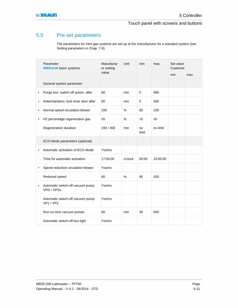
5 Controller
Touch panel with screens and buttons
MB20-200-Labmaster – TP700
Operating Manual – V 4.1 - 06/2014 - STD
Page
5-21
5.5 Pre-set parameters
The parameters for inert gas systems are set up at the manufacturer for a standard system (see Setting parameters in Chap. 7-9).
Parameter MBRAUN basic systems
Manufacturer setting value
Unit min max. Set value Customer
min max
General system parameter
• Purge box: switch off autom. after 60 min 0 999
• Antechambers: lock inner door after 60 min 0 500
• Normal speed circulation blower 100 % 60 100
• H2 percentage regeneration gas ≥5 % <5 ≥5
Regeneration duration 150 / 300 min no limit
no limit
ECO-Mode parameters (optional)
• Automatic activation of ECO-Mode Yes/no
Time for automatic activation 17:00:00 o'clock 00:00 24:00:00
• Speed reduction circulation blower Yes/no
Reduced speed 60 % 60 100
• Automatic switch-off vacuum pump. VPG / VPGL
Yes/no
Automatic switch-off vacuum pump. VP1 / VP2
Yes/no
Run-on time vacuum pumps 60 min 30 600
Automatic switch-off box light Yes/no

5 Controller
Pre-set parameters
Page
5-22
MB20-200-Labmaster – TP700
Operating Manual – V 4.1 - 06/2014 - STD
Parameter MBRAUN basic systems
Manufacturer setting value
Unit min max. Set value Customer
min max
Gas purifier RKM / LMF
• Start circulation automatically after regeneration
Yes/no
• Regenerate automatically Yes/no
Regeneration interval 25 H 24 999
• Alarm threshold LMF analyser 1 V 0,1 9,9
Box min max.
• Box pressure: upper operating limit +4,0 mbar -13,5 +14,5
• Box pressure: lower operating limit -4,0 mbar -14,5 +13,5
• Hysteresis Upper Limit 2,0 mbar 0,5 calculated
• Hysteresis Lower Limit 2,0 mbar 0,5 calculated
• Box pressure: upper alarm limit +15,0 mbar -14,0 +15,0
• Box pressure: lower alarm limit -15,0 mbar -15,0 +14,0
• H2O alarm 20,0 ppm 5,0 499,0
• O2 alarm 20,0 ppm 5,0 999,0
2-box system: pressure monitoring
• Maximum pressure difference Box 1 – Box 2
1 mbar 0 5
Freezer / box cooling
• Target value temp. freezer -35 °C -40 +10
• Temperature alarm freezer -25 °C -40 25
• Target value temp. box cooling 20 °C 10 40
• Temperature alarm box cooling 30 °C 10 50

5 Controller
Touch panel with screens and buttons
MB20-200-Labmaster – TP700
Operating Manual – V 4.1 - 06/2014 - STD
Page
5-23
Parameter MBRAUN basic systems
Manufacturer setting value
Unit min max. Set value Customer
min max
Box automatic purge
• Automatic purge in case of O2 exceeding
Yes/no
O2 limit value 100,0 ppm 10,0 999,9
Box pressure monitoring
• Maximum pressure difference Box 1 - Box2
1 mbar 0 5
Antechambers min. max.
• Threshold value intermediate refill 400 mbar 1x10⁻² 50
• Threshold value vacuum leak test 5x10⁻¹ mbar 1x10⁻² 10
• Threshold value final vacuum 5x10⁻¹ mbar 1x10⁻² 10
• Number of pump refill cycles 1 1 10
• Maximum evacuation time 5 min 1 20
• Maximum leakage rate 3 steps 1 10

5 Controller
Overview
Page
5-24
MB20-200-Labmaster – TP700
Operating Manual – V 4.1 - 06/2014 - STD
5.6 Overview
5.6.1 Navigation from the start screen (System components und functions)

5 Controller
Touch panel with screens and buttons
MB20-200-Labmaster – TP700
Operating Manual – V 4.1 - 06/2014 - STD
Page
5-25
5.6.2 Menu screen selection

5 Controller
Overview
Page
5-26
MB20-200-Labmaster – TP700
Operating Manual – V 4.1 - 06/2014 - STD
5.6.3 Components screen
5.6.3.1 Gas Purification RKM
1
RK
M-S
yste
m
2
RK
M-S
yste
m

5 Controller
Touch panel with screens and buttons
MB20-200-Labmaster – TP700
Operating Manual – V 4.1 - 06/2014 - STD
Page
5-27
5.6.3.2 Gas Purification with LMF
1 L
MF
2 L
MF

5 Controller
Overview
Page
5-28
MB20-200-Labmaster – TP700
Operating Manual – V 4.1 - 06/2014 - STD
5.6.3.3 Inert Gas-Box
See chapter 5.6.2 Menu screen selection
5.6.3.4 Antechamber (Automatic) A
ntec
ham
ber
(A
utom
atic
)

5 Controller
Touch panel with screens and buttons
MB20-200-Labmaster – TP700
Operating Manual – V 4.1 - 06/2014 - STD
Page
5-29
5.6.3.5 Antechamber (Manual)
Ant
echa
mbe
r (
Man
ual)

5 Controller
Overview
Page
5-30
MB20-200-Labmaster – TP700
Operating Manual – V 4.1 - 06/2014 - STD
5.6.4 Service screen selection

5 Controller
Touch panel with screens and buttons
MB20-200-Labmaster – TP700
Operating Manual – V 4.1 - 06/2014 - STD
Page
5-31

6 Basic operating modes
MB20-200-Labmaster – TP700
Operating Manual – V 4.1 – 06/2014 - STD
Page
6-1
6.1 Introduction ...................................... ......................................................6-2 6.1.1 Overview of operating modes and activities ........................................................... 6-2
6.2 Safety ............................................ ..........................................................6-4 6.2.1 Operating Manual ................................................................................................... 6-4 6.2.2 Personnel ............................................................................................................... 6-4 6.2.3 Environment ........................................................................................................... 6-5
6.3 Prerequisites for operation ....................... ............................................6-6 6.3.1 Organisational preparation ..................................................................................... 6-6 6.3.2 Check connections ................................................................................................. 6-6
6.4 (Initial) commissioning ........................... ...............................................6-7 6.4.1 Switch system on ................................................................................................... 6-7 6.4.2 Inertising the box (pre-purging) .................................. Error! Bookmark not defined. 6.4.3 Inertisation of the pipework .................................................................................... 6-8
6.5 System in normal operation ........................ ..........................................6-9 6.5.1 Regeneration operation .......................................................................................... 6-9 6.5.2 Circulation operation ............................................................................................ 6-10 6.5.3 Antechamber cycles evacuate - refill .................................................................... 6-10
6.6 System in ECO-Mode (optional) ..................... ..................................... 6-10
6.7 Setting up the controller for the specific processe s ......................... 6-11 6.7.1 Adapting parameters to process values (test run) ................................................ 6-11
6.8 Switching the system off .......................... ........................................... 6-12 6.8.1 Prerequisites ........................................................................................................ 6-12 6.8.2 Deactivating the system ....................................................................................... 6-12
6.9 System in maintenance operation ................... ................................... 6-13 6.9.1 Maintenance ......................................................................................................... 6-13 6.9.2 Repair ................................................................................................................... 6-13
6.10 Damage to the system – behavior in case of emergenc y .................. 6-14 6.10.1 Damage to the system ......................................................................................... 6-14 6.10.2 Eliminating faults .................................................................................................. 6-14 6.10.3 Behavior in case of emergency ............................................................................ 6-14
6.11 De-installing the system – disposing of components ....................... 6-17 6.11.1 Disposal ............................................................................................................... 6-17

6 Basic operating modes
Introduction
Page
6-2
MB20-200-Labmaster – TP700
Operating Manual – V 4.1 – 06/2014 - STD
6 Basic operating modes
6.1 Introduction
This chapter provides an overview of the operation of the system in the course of the life cycle with commissioning – operation – decommissioning – uninstalling and disposal.
The safety of a system depends on the correct use and operation of the system.
The following overview shows the operating modes, the basic activities, and names the responsibilities and authorisations.
6.1.1 Overview of operating modes and activities
Operating mode Activities Responsible / authorised See chap.
Commissioning Organisational preparation Operator of the system 4
Check connections *) Technician / User / MBRAUN Service
4
Purging the box *) Technician / User / MBRAUN Service
8.5
Purging the pipework / the entire system(RKM + vacuum pump + additional equipment) *)
Technician / User / MBRAUN Service
Standard processes
Set up specific parameters(if necessary)
if necessary Administrator / authorised people
5
Operation in circulation mode
Trained users 7.3.2
Operation in regeneration mode
Trained users 7.3.2
Antechamber processes Trained users 9
ECO-Mode (optional)
Set up parameters if necessary Administrator / authorised people
56 A
Service / Maintenance
For more details, see Chap. 12 Maintenance
In-house service personnel / MBRAUN Service
812

6 Basic operating modes
MB20-200-Labmaster – TP700
Operating Manual – V 4.1 – 06/2014 - STD
Page
6-3
Operating mode Activities Responsible / authorised See chap.
Cooling Trained AC technician 10 A ff
Electrical system Trained electrician
Decommissioning Switching off the system In-house service / Trained users
6.8
Deactivation (short-term/ long-term)
In-house service / Trained users
6.8
Disposal of components of the system
Operator of the system / Trained users
6.11
*) With commissioned installation by the manufacturer: MBRAUN Service technician

6 Basic operating modes
Safety
Page
6-4
MB20-200-Labmaster – TP700
Operating Manual – V 4.1 – 06/2014 - STD
6.2 Safety
6.2.1 Operating Manual
DANGER
Incorrect operation of the system can cause unknown risks, which can result in severe to deadly injuries
► Always keep operating manual within reach of the system
► The personnel must read and understand the operating manual
► Heed operating manual during all work: this includes preparation, transport, storage, installation, commissioning and service!
► Always heed safety instructions in this operating manual
► Heed safety instructions for third-party components (see supplier documentation).
6.2.2 Personnel
WARNING
Personal injury and environmental damage due to incorrect operation
► The system may only be operated and maintained by suitable qualified* and specially-trained personnel who have reached the legal minimum age.
► Temporary personnel or personnel being trained, taught or engaged in general training may only operate the system under the constant supervision of an experienced person!
► Work on electrical equipment of the system and its accessories may only be performed by a trained electrician or trained people under the direction and supervision of a trained electrician according to the electrotechnical regulations.
► Work on systems with coolants may only be performed by trained air conditioning technicians.
* A suitably qualified person is anyone who due to his/her specialist training, as well as knowledge of the applicable stipulations, can assess the work assigned to him/her and can recognize possible hazards.

6 Basic operating modes
MB20-200-Labmaster – TP700
Operating Manual – V 4.1 – 06/2014 - STD
Page
6-5
6.2.2.1 Responsibilities for operation of the system
WARNING
Endangerment of products and people with operation by several people, triggered by potential misunderstandings or uncoordinated operation.
If the deployment of several people is required:
► Define responsibilities clearly (see Chap. 5, Password concept)
► Explain steps precisely to one another
► If necessary, follow the process-specific standard operating manual
6.2.2.2 Protective equipment / additional equipment
WARNING
Personal injury in case of missing (additional) protective equipment and functions
Heed all details of this operating manual relating to protective equipment and accessories.
► Wear personal protective equipment (PPE) as described for the task in question in the operating manual
► Additional equipment and functions for personal protection must always be used with the use of processes / materials that threaten health and the environment.
6.2.3 Environment
WARNING
Environmental damage in case of incorrect application / incorrect operation
Heed all details of this operating manual relating to protective equipment
► Discharge of exhaust in an in-house exhaust system
► Proper disposal of components
► Adhere to all applicable national regulations and provisions
! Please note
- Chapter 3 Safety
- Chapter 6.11 De-installing the system – disposing of components

6 Basic operating modes
Prerequisites for operation
Page
6-6
MB20-200-Labmaster – TP700
Operating Manual – V 4.1 – 06/2014 - STD
6.3 Prerequisites for operation
6.3.1 Organisational preparation
Prerequisites:
> The operating manual is ready
> The personnel has read and understood the operating manual
> The personnel is instructed and trained
> Personal protective equipment (insofar as required) is ready
System-specific processes and materials (responsibility of the customer)
> Processes and process materials used have been checked for their hazard potential
> If necessary, a process-specific standard operating manual created by the customer is ready
6.3.1.1 Setting up the service book
� Note beginning of operation (for determination of the regeneration cycle)
� Scheduling for calibration of the sensors, maintenance intervals
6.3.2 Check connections
Prerequisites
> All required instructions in the foregoing chapter have been heeded
> All supply lines and connections for gases , electricity and cooling water have been made properly and checked
Exhaust:
> Exhaust line for used regeneration gas created properly
> Exhaust discharge of the vacuum pump(s) assured
> Exhaust gases that harm the environment and health are connected to an in-house exhaust system
> With use of regenerative solvent filters: connection to an explosion-proof exhaust system is required
Safety equipment:
DANGER
Personal injury due to lacking or non-functional safety equipment!
► The normal operation of the system is only permissible with all associated, correctly-installed and functioning safety equipment!

6 Basic operating modes
MB20-200-Labmaster – TP700
Operating Manual – V 4.1 – 06/2014 - STD
Page
6-7
6.4 (Initial) commissioning
6.4.1 Switch system on
6.4.1.1 Activate system
The main switch is on the control cabinet of the system.
Activate system:
► Turn main switch to I (ON)
→ After the activation, the system performs a self-test.
! All error messages that appeared before the start screen are controller errors and can only be remedied by MBRAUN Service.
6.4.1.2 Start messages
By default, MBRAUN systems are equipped with a PLC-controlled touch panel. The touch panel is the central operating and display unit of the system. It is in a central, easy-to-see position.
After performing the self-test, the start indicator appears:
Start screen 01100-0
Depending on how the system is equipped, the start screen may look different. See Chap. 5 Controller.

6 Basic operating modes
(Initial) commissioning
Page
6-8
MB20-200-Labmaster – TP700
Operating Manual – V 4.1 – 06/2014 - STD
6.4.2 Purging the box
If an inert gas box system contains ambient air – as on commissioning, in case of error or after service work – the box must be purged before switching on circulation operation.
NOTICE
Ambient air (oxygen and moisture content) damages gas purifier purifiers!
� Never switch a box with ambient air into circulation operation!
Before switching a (regenerating) purifier into circulation operation:
► Replace ambient air with operating gas
! Please inform yourself initially about the measurement devices in Chap. 8.4 Sensor monitoring. To purge the box, please follow the description in Chap 8.5 Manual purge of the box (without / with measurement devices).
! If the system is equipped with a pressure control valve, when the trigger pressure is exceeded, gas escapes through the pressure control valve into the laboratory or into the exhaust system.
Before switching the purifier into circulation oper ation:
Inertisation method
► Purge box with inert gas from external source until there is an O2 level in the box atmosphere of less than 100 ppm
After manual inertisation: adjust measurement devic es
► Activate measurement devices
► Wait until the sensors work and the desired atmosphere reigns.
6.4.3 Inertisation of the pipework
Before connecting to the gas purifier / before comm issioning:
In modular systems (multi-box operation), whose pipework has a larger volume:
► Purge pipework with operating gas using the purge valve.

6 Basic operating modes
MB20-200-Labmaster – TP700
Operating Manual – V 4.1 – 06/2014 - STD
Page
6-9
6.5 System in normal operation
The system delivered by MBRAUN is set up for normal operation (see Chap. 5.6.1 Pre-set parameters).
Normal operation of the components of the system is described in
Chap. 7 Gas purification system
Chap. 8 Inertgas box
Chap. 9 Antechamber
Chap. 10
Additional equipment (optional)
6.5.1 Regeneration operation
The RKM 1 purifying unit is regenerated by the manufacturer before delivery.
On initial commissioning, the circulation operation can run via the first purifier (RKM1).
System with 2 purifiers:
Before initial commissioning by the customer:
► Regenerate the purification unit RKM2
The distances between the regeneration cycles vary according to the system, usage type and time (see Chap. 7.3.2.3). They can be determined as follows:
Method for determining an appropriate interval for the regeneration:
After initial commissioning: wait for detectable performance drop
When there is a performance drop, note the operating duration.
The operating duration less 10 hours = reference value for the intervals between the regeneration cycles
In case of recommissioning after a longer time:
► First regenerate purifier.

6 Basic operating modes
System in ECO-Mode (optional)
Page
6-10
MB20-200-Labmaster – TP700
Operating Manual – V 4.1 – 06/2014 - STD
6.5.2 Circulation operation
Circulation operation can take place:
� Using a regenerated purifier (RKM)
� Always only using one purifier.
! The activation of the circulation is only allowed if the box is inertised and the oxygen content of the box atmosphere is < 100ppm – see Chap. 7.3.2.1.
While the inert gas box is in operation and the measurement devices are switched on, the concentration of water vapor, oxygen and box pressure is monitored and continuously displayed on the touch panel (see Chap. 5):
6.5.3 Antechamber cycles evacuate - refill
Materials that are required for a process are brought into the inert gas box via the antechamber and removed from there. During the loading, the ambient air is replaced in the antechamber step by step with operating gas (inert gas) and the box atmosphere is adapted. This requires several cycles of evacuation and refilling.
The parameters for the values of number, duration and pressure of the respective cycles can be set process-specifically.
See Chapter 9.5.2.2: Antechamber parameters
6.6 System in ECO-Mode (optional)
ECO-Mode provides an energy-saving operating mode.
See optional Chapter 6 A ECO-Mode

6 Basic operating modes
MB20-200-Labmaster – TP700
Operating Manual – V 4.1 – 06/2014 - STD
Page
6-11
6.7 Setting up the controller for the specific processes
6.7.1 Adapting parameters to process values (test run)
Depending on the customer-specific process, it may be necessary to adapt the parameters for processes. For this, test runs should be evaluated and logged (test run in circulation mode, determination of the regeneration intervals).
! The adaptation of the parameters is permitted to the extent specified in "Proper use" - see Chap. 4.
An adaptation of the limit values ensures the specific conditions for the respective processes.
Typical settings / operating values are
� Alarm limits for oxygen and water vapor
� Upper and lower limits for box pressure
� Maximum evacuation time for the antechamber
� Regeneration intervals
Input parameters see Chapter 5.3.5 Parameter screen.

6 Basic operating modes
Switching the system off
Page
6-12
MB20-200-Labmaster – TP700
Operating Manual – V 4.1 – 06/2014 - STD
6.8 Switching the system off
6.8.1 Prerequisites
The system should only be switched off for the following reasons:
� in case of emergency
� during extended maintenance (e.g. in case of replacement of purifiers, particle filters or valves)
� if the system will not be used for a longer period (4 weeks and longer)
6.8.2 Deactivating the system
The system may only be switched off if all running processes are ended and deactivated, e.g. regeneration programme, circulation operation and antechamber processes.
The main switch is on the control cabinet of the system.
Deactivating the system:
► Turn main switch to O (OFF).
! If the gas purifier is switched off for a longer period of time, the concentration of oxygen and water vapor inside the inert gas box increases continuously.

6 Basic operating modes
MB20-200-Labmaster – TP700
Operating Manual – V 4.1 – 06/2014 - STD
Page
6-13
6.9 System in maintenance operation
6.9.1 Maintenance
Chapter 12 describes the maintenance cycles and work for an inert gas system. It is specified there who is authorised for which work.
DANGER
Risk of suffocation when performing work on an open inert gas box!
Before opening a box
► Always replace inert gas atmosphere with ambient air
► Do not place head in an antechamber if it is not ensured that the antechamber is filled with ambient air (O2 content > 19.5%).
► An electrical inspection must be performed after all maintenance/decommissioning.
See Inspection and maintenance chapter
► All modifications must be documented by the customer and if necessary agree upon with MBRAUN .
Recommendation
Always keep the following spare parts on hand, for example
� Gloves
� Particle filter
� Oxygen and moisture sensors
6.9.2 Repair
Repair work that is not described in this manual may only be performed by MBRAUN Service.
DANGER
Personal injury due to non-authorised work on the system!
Maintenance work (repairs) may only be performed by MBRAUN Service.
In case of damage to the system:
► Contact MBRAUN Service.

6 Basic operating modes
Damage to the system –in case of emergency
Page
6-14
MB20-200-Labmaster – TP700
Operating Manual – V 4.1 – 06/2014 - STD
6.10 Damage to the system –in case of emergency
6.10.1 Damage to the system
DANGER
Personal injury due to damage to the system!
Depending on the type and scope of the damage and the process materials used, unknown risks can arise!
If the system
� Demonstrates visible damage
� Is not working in the framework of the specifications
� Was not stored properly
� Was subjected to extreme, improper transport conditions
If one of these points is relevant, then
� Take the system out of operation!
� Secure it against unauthorised or unintentional commissioning!
� Contact MBRAUN Service.
All malfunctions must be reported to the internal service department or the MBRAUN Service Department immediately!
Malfunctions must be documented in the service book
6.10.2 Eliminating faults
The elimination of faults – with cancellation and power failure routines - is described in Chapter 11.
The circuit diagram describes the basic principles for searching for faults in the electrical system (Chap. 13).
6.10.3 Behavior in case of emergency
Prerequisites:
Behavior in case of fire in the room depends on the process materials used and the conditions on-site. Therefore, the operator must create an emergency plan according to the specific circumstances and regulate these in a standard flow plan (see chap. Installation). This plan must be displayed in a visible place in the operating area. The personnel must be instructed about behavior in case of emergency and trained regularly.
► The operator of the system is obligated to familiarise him/herself with the flows in case of emergency.

6 Basic operating modes
MB20-200-Labmaster – TP700
Operating Manual – V 4.1 – 06/2014 - STD
Page
6-15
6.10.3.1 Oxygen concentration in the room air drops
WARNING
Risk of suffocation in rooms with oxygen content < 19.5%
► Only enter room with compressed air bottle-driven breathing protection!
Troubleshooting:
► By responsible specially-trained person
► In case of questions, contact MBRAUN Service.
! Recommendation
Use a wearable personal oxygen warning device that warns you if there is a critical lack of oxygen concentration in the ambient air.
► Ask MBRAUN Service.
If the oxygen content in the room air sinks below < 19.5%:
► Trigger and alarm / warn your colleagues
► Inform the operation's safety officer
In case of gas supply faults:
► Interrupt the gas feed: close the main input valve
In case of faults in the exhaust air system:
► Interrupt the gas supply
► Interrupt the circulation
► Leave the room immediately

6 Basic operating modes
Damage to the system –in case of emergency
Page
6-16
MB20-200-Labmaster – TP700
Operating Manual – V 4.1 – 06/2014 - STD
6.10.3.2 Electrical accidents
In case of risks to people due to electrical malfunctions:
► Switch off main switch on the control cabinet!
► Inform the emergency services
► Secure system against unauthorised or unintentional commissioning
► All malfunctions must be reported to the internal service department or the MBRAUN Service Department immediately!
► Malfunctions must be documented in the service book
6.10.3.3 Escaping of process gases and materials
► Follow your standard flow plan (see Chap. 4.1 Preparation and installation).
► Perform a leak check and eliminate the error.
► In case of questions, contact MBRAUN Service.
6.10.3.4 Fire in the room Behavior in case of fire in the room depends on the process materials used and the conditions on-site.
► Follow your operational standard operational plan (SOP) for the case of fire.(see Chap. 4.1 Preparation and installation).

6 Basic operating modes
MB20-200-Labmaster – TP700
Operating Manual – V 4.1 – 06/2014 - STD
Page
6-17
6.11 De-installing the system – disposing of components
6.11.1 Disposal
DANGER
Risk of personal injury! Risk of environmental pollution!
If during disposal work, you must work with hazardous materials, heed the following:
► Wear personal protective equipment (PPE):appropriate breathing protection full mask (with suitable filter), protective gloves and eye protection!
► The user is responsible for heeding national and international regulations. He must adhere to health, safety and environmental guidelines!
The following components or materials mentioned can be contaminated with toxic substances and pollute the environment if they are not disposed of properly.
None of the following components and materials mentioned may be allowed to reach the environmental atmosphere, sewer system, bodies or water or the earth:
� Dispose of gas purifying system (with purifiers, vacuum pumps, blower), components of the system, and oil from the vacuum pumps according to the applicable local and national regulations.
� Box particle filterDispose of used filters according to the locally-applicable national guidelines.
� Solvent filter (active carbon) The filter material of solvent filters (active carbon) can be contaminated by process chemicals and solvents. Heed the requirements from the safety data sheets (material data sheets). Dispose of the filter material according to the locally-applicable national guidelines.
� Exhaust Discharge all exhaust gases via an appropriate exhaust gas disposal system!
It is the sole responsibility of the operator during the disposal of contaminated material to prevent any environmental pollution.
Procedure for de-commissioning: See Chap. 12

6 Basic operating modes
De-installing the system – disposing of components
Page
6-18
MB20-200-Labmaster – TP700
Operating Manual – V 4.1 – 06/2014 - STD

6 A. Eco-Mode
MB20-200-Labmaster – TP700
Operating Manual – V 4.1 – 06/2014 - STD
Page 6A-1
6 A.1 Particularities in ECO-Mode operation .................................................... 2
6 A.1.1 Box light ..................................................................................................................... 2
6 A.1.2 Circulation operation and blower ................................................................................ 2
6 A.1.3 Regeneration operation and vacuum pump (VPG) .................................................... 3
6 A.1.4 Antechambers and vacuum pump (VP1) .................................................................... 4
6 A.2 Safety ......................................................................................................... 5
6 A.2.1 Intended Use .............................................................................................................. 5
6 A.2.2 Misuse ........................................................................................................................ 5
6 A.3 Controller ................................................................................................... 6
6 A.3.1 Controller: Navigation overview .................................................................................. 6
6 A.4 Parameter .................................................................................................. 7
6 A.4.1 Automatic ................................................................................................................... 7
6 A.4.2 Blower ........................................................................................................................ 8
6 A.4.3 Box pressure regulation via blower ............................................................................ 9
6 A.4.4 Vacuum pump gas purifier (VPG + VPGL) ............................................................... 10
6 A.4.5 Vacuum pump antechamber (VP1+2) ...................................................................... 10
6 A.4.6 Box light ................................................................................................................... 11
6 A.5 Activate/deactivate ECO-Mode ............................................................... 11

6 A. Eco-Mode
Particularities in ECO-Mode operation
Page 6A-2 MB20-200-Labmaster – TP700
Operating Manual – V 4.1 – 06/2014 - STD
6 A Eco-Mode
6 A.1 Particularities in ECO-Mode operation
ECO-Mode provides an energy-saving operating mode that can be set for inactive operation overnight or on the weekend.
The ECO-Mode function can also be activated automatically at a defined point in time(e.g. daily at 5:00pm).
With activated ECO operating mode, the lowering of the box pressure with exceeding of the upper operating limit does not happen due to pumping out with the help of the vacuum pump, but rather by opening the additional valve (VDA), which is installed directly on the gas output of the blower. This regulation allows operation of the box only in over pressure. At the start the lower operating limit is set to + 2 mbar and the upper operating limit is adapted accordingly.
When ECO-Mode is deactivated, the original operating limits of the box pressure are reactivated.
As needed, the blower can work at reduced frequency, the vacuum pump and box light can be switched off automatically.
The minimum circulation should not drop below 10x the volume change of the enclosed box volume since otherwise there can be a loss of the quality of the box atmosphere.
Note: Initially please follow the descriptions of operation in normal operation - see Chapters 5 to 9.
6 A.1.1 Box light
The box light can be switched ON and OFF manually while in ECO-Mode (� function keys screen)
6 A.1.2 Circulation operation and blower
The energy savings is achieved through a reduction of the frequency of the speed of the blower and through switching off the vacuum pump(s).
Pressure regulation
The pressure regulation takes place during the circulation in ECO-Mode via an additional output valve (VDA) on the blower output.
In ECO-Mode, the operating limits are adapted automatically in a range between ≥ + 2 mbar (lower operating limit) and ≥ + 3 mbar (upper operating limit) with a difference of at least 1 mbar.
As soon as ECO-Mode is deactivated, the previously-set operating limits are automatically reactivated.
Oxygen and moisture content
If the oxygen or moisture content in the box exceeds an adjustable limit value (pre-set: 10 ppm), the speed of the blower is increased to the normal speed. If the H2O and O2 concentrations drop ≤ 1 ppm, the blower switches back to the speed of the ECO-Mode.
6 A. Eco-Mode
MB20-200-Labmaster – TP700
Operating Manual – V 4.0 – 11/2013 - STD
Page 6A-3
6 A.1.3 Regeneration operation and vacuum pump (VPG)
Regeneration operation can also be performed with activated ECO-Mode: the vacuum pump (VPG) is ready for the regeneration program.
Case 1:
> ECO-Mode is activated> Parameter "automatic switch-off of the vacuum pump" - "Yes" is set
When the regeneration program starts, the vacuum pump (in step 2) is switched ON. After completing the regeneration program (step 17), the pump is switched OFF again. Manual switching off of the vacuum pump during regeneration is not possible (see Chap. 7.3.2.3 Basic principles of the regeneration program).
Case 2:
> Parameter "automatic switch-off of the vacuum pump" - "Yes" > ECO-Mode is switched on after the regeneration has started
When the regeneration program is completed, the vacuum pump (in step 17) remains switched ON.

6 A. Eco-Mode
Particularities in ECO-Mode operation
Page 6A-4 MB20-200-Labmaster – TP700
Operating Manual – V 4.1 – 06/2014 - STD
6 A.1.4 Antechambers and vacuum pump (VP1)
Prerequisite
> ECO-Mode is switched on and
ECO-Mode parameters
> If one or several manually-operated antechambers are connected to the vacuum pump in question:
These vacuum pumps are only switched off once when activating the ECO-Mode.
Note: The PLC does not receive any information about whether and when these antechambers were evacuated. Therefore, there can be no automatic switching off of the connected vacuum pump after an evacuation cycle!
Manually-operated antechambers
(without electrical valves or sensors)
> Only automatic antechambers are present – main antechamber and mini-antechamber / - - (insofar as present):
With activation of ECO-Mode:
→ The vacuum pump VPG is switched OFF.
If an automatic antechamber cycle starts:
→ The vacuum pump is switched ON and
→ After 30 minutes switched OFF if no antechamber cycle is active.
Automatic antechambers
6 A. Eco-Mode
MB20-200-Labmaster – TP700
Operating Manual – V 4.0 – 11/2013 - STD
Page 6A-5
6 A.2 Safety
6 A.2.1 Intended Use
Operation in ECO-mode allows energy-saving operation of the inert gas system in stand-by operation.
6 A.2.2 Misuse
If the upper operating limit of the system is set to a value < 0 mbar and the box should be kept at under pressure, the ECO-Mode may not be switched on.

6 A. Eco-Mode
Controller
Page 6A-6 MB20-200-Labmaster – TP700
Operating Manual – V 4.1 – 06/2014 - STD
6 A.3 Controller
6 A.3.1 Controller: Navigation overview
Start screen: 01102-0
With activated ECO-Mode, there is an indicator on the start screen (bottom right)
Calling the ECO-Mode parameters screen
► Touch Menu button
Menue Screen Selection 01120
On the "Menue Screen Selection":
► Touch Parameter ECO-Mode button
ECO-Mode parameters 01121
See below for description

6 A. Eco-Mode
MB20-200-Labmaster – TP700
Operating Manual – V 4.0 – 11/2013 - STD
Page 6A-7
6 A.4 Parameter
ECO-Mode parameters 01121
The manufacturer delivers the system with the following settings:
(see Chap. 5.6 Basic parameters)
6 A.4.1 Automatic
Prerequisite
> Automatic activation is activated (Yes)
► Enter standard time specification for automatic switching on
Note:
The weekdays are not taken into consideration since ECO-Mode remains activated until it is manually deactivated. Therefore the system remains in ECO-Mode on Sundays, for example.
Automatic
With activated ECO-Mode:

6 A. Eco-Mode
Parameter
Page 6A-8 MB20-200-Labmaster – TP700
Operating Manual – V 4.1 – 06/2014 - STD
6 A.4.2 Blower
.
Prerequisite
> ECO-Mode is switched on
Reduction of the blower speed:
► Enter value of the reduced speed� Input range: 60 -100 %
ECO-Mode parameters
► Reduced speed
Blower Speed Reduction: Yes
No
Speed is reduced
Do not reduce speed
Please note:
Limit value O2 and H2O is less than < limit value for the activation of the automatic box purging!
Parameter
Increase speed to 100%
with adjustable limit value O2 and H2O content
Pre-set by MBRAUN:
10 ppm for O2 and H2O:
The limit values must be set so they are equally high

6 A. Eco-Mode
MB20-200-Labmaster – TP700
Operating Manual – V 4.0 – 11/2013 - STD
Page 6A-9
6 A.4.3 Box pressure regulation via blower
The value of the lower operating limit is limited to ≥ +2 mbar,
The value of the upper operating limit remains unchanged if it is set to ≥ + 3 mbar; otherwise it is set to 3 mbar. (See 6 A.1.2).
Explanation of regulation via VDA / VPA – see also specification for ECO-Mode
Box pressure parameters 01500-2
Setting operating limits
Blower speed in normal operation and in ECO-Mode
Normal
operation Eco-Mode
Blower type
Gas purifier
without LMF
Gas purifier with
LMF *)
BL01 Speed 100% 60 - 100% 80 - 100 %
Frequency 50 Hz 30 Hz – 50 Hz 40 Hz – 50 Hz
*) For work with release of gaseous contamination:
Recommendation: ECO-Mode should not be activated.
! The blower speed of 100% constantly ensures that gas contamination is
removed from the box atmosphere as quickly as possible.
*) See also Chapter 7, Parameters: Blower speed in normal operation

6 A. Eco-Mode
Parameter
Page 6A-10 MB20-200-Labmaster – TP700
Operating Manual – V 4.1 – 06/2014 - STD
6 A.4.4 Vacuum pump gas purifier (VPG + VPGL)
Prerequisite
> ECO-Mode is switched on
> Automatic switch-off… Yes
VPG / VPGL (Gas purifier RKM + LMF)
- Automatic switch-off of the VPG (and if necessary of the VPGL).
With activation of a regeneration (RKM or LMF), the required pump is switched on automatically and switched off again after completing the regeneration.
Note:
The box pressure regulation is accomplished via the additional gas output valve.
ECO-Mode parameters
� Vacuum pumps
� Gas purifier
see also 6 A.4.3
6 A.4.5 Vacuum pump antechamber (VP1+2)
VP1 (Separate pump antechamber)
If the antechamber is equipped with a separate vacuum pump: the vacuum pump is switched off 60 minutes after the last evacuation of the antechamber.
Time can be set from 30..600 min.
ECO-Mode parameters
� Vacuum pump
� Antechambers
see also 6 A.4
Only manually-operated antechambers (without electrical valves or sensors):
The PLC does not receive any information about whether and when these antechambers are evacuated. Therefore, there can be no automatic switching off of the connected vacuum pump after an evacuation cycle!
These vacuum pumps are only switched off once when activating the ECO-Mode.
Note
Manually-operated antechambers
see also 6 A.4
To execute an antechamber cycle (loading), the vacuum pump can be switched on manually on the touch panel using the function key on the function screen and then switched off again if needed.
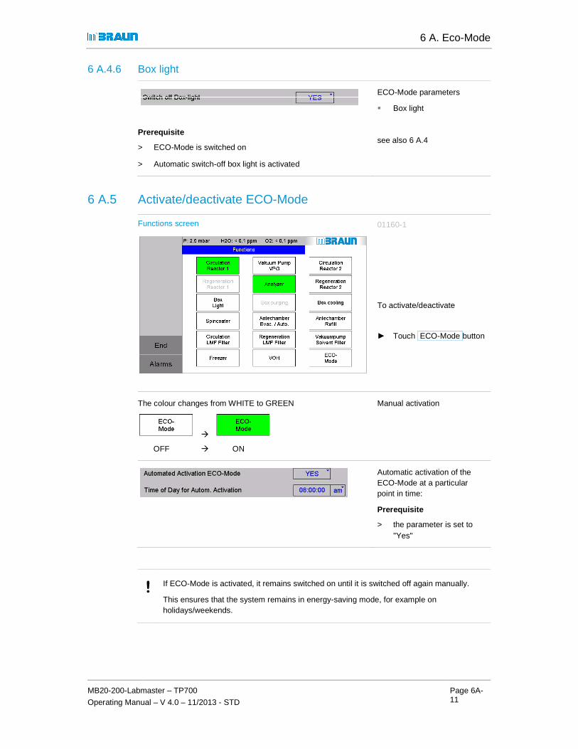
6 A. Eco-Mode
MB20-200-Labmaster – TP700
Operating Manual – V 4.0 – 11/2013 - STD
Page 6A-11
6 A.4.6 Box light
Prerequisite
> ECO-Mode is switched on
> Automatic switch-off box light is activated
ECO-Mode parameters
� Box light
see also 6 A.4
6 A.5 Activate/deactivate ECO-Mode
Functions screen 01160-1
To activate/deactivate
► Touch ECO-Mode button
The colour changes from WHITE to GREEN
�
OFF � ON
Manual activation
Automatic activation of the ECO-Mode at a particular point in time:
Prerequisite
> the parameter is set to "Yes"
! If ECO-Mode is activated, it remains switched on until it is switched off again manually.
This ensures that the system remains in energy-saving mode, for example on holidays/weekends.

6 A. Eco-Mode
Activate/deactivate ECO-Mode
Page 6A-12 MB20-200-Labmaster – TP700
Operating Manual – V 4.1 – 06/2014 - STD

7 Operation of gas purifier
MB20-200-Labmaster – TP700
Operating Manual – V 4.1– 06/2014 - STD
Page
7-1
7.1 Introduction ...................................... ......................................................7-2 7.1.1 Basic rules for the safe operation of the system ..................................................... 7-2 7.1.2 Use of a vacuum pump for several system components ........................................ 7-2
7.2 Safety Gas purifier ............................... ..................................................7-3 7.2.1 Ambient air ............................................................................................................. 7-3 7.2.2 H2 mixture for regenerating H2O and O2 reactors .................................................. 7-3 7.2.3 Solvents – solvent filter (LMF) ................................................................................ 7-4
7.3 Gas purifier (O 2 and H 2O) .......................................................................7-5 7.3.1 Gas purifier controller RKM – Navigation overview ................................................ 7-5 7.3.2 Gas purifier operation (RKM for H2O + O2) .......................................................... 7-11
7.4 Gas Purifier Solvents (LMF) ....................... ......................................... 7-25 7.4.1 Technical Data ..................................................................................................... 7-25 7.4.2 Safety ................................................................................................................... 7-25 7.4.3 Manual valve controlled solvent filter LMF ........................................................... 7-26 7.4.4 PLC-controlled, regenerative solvent filter LMF ................................................... 7-27 7.4.5 Solvent sensor (Option) ........................................................................................ 7-31

7 Operation of gas purifier
Introduction
Page
7-2
MB20-200-Labmaster – TP700
Operating Manual – V 4.1 – 06/2014 - STD
7 Operation of gas purifier
7.1 Introduction
This chapter shows the operation of the following functions:
� Gas purifier for the removal of oxygen and moisture (O2 and H2O)
� Solvent filter (LMF)
The operating modes "Circulation" and "Regeneration" are described.
Functions for the gas and pressure management within the box are described in Chap. 8 Inert gas box.
7.1.1 Basic rules for the safe operation of the system
► Always note that the connections/screw connections are made correctly (according to Chap. 4 Installation and Chap. 6 Commissioning and principles of operation).
► Maintain the operating flows according to this operating manual:
� Switch on the circulation only after purging of the box (see Chap. 8, Inert gas box).
� The intervals for the regeneration of the reactors depend on the processes used. Determine the time at which a regeneration of your system's reactors is required.
� Do not wait with the regeneration of the reactors until they are completely saturated.
� After each regeneration, empty the container with the regeneration condensate
► PLC: adhere to permissible parameter ranges The functions of the gas purifying system are defined and controlled by the parameters of the PLC.
In case of equipment with a pressure control valve in the gas purifier (optional):
► Perform the function test for the pressure control valve regularly
7.1.2 Use of a vacuum pump for several system components
Please note:
The quality of the regeneration processes is compromised with a lot of antechamber activity.
→ Box pressure regulation and antechamber processes take precedence.
→ During regeneration, evacuation steps of the regeneration process running in parallel will be interrupted – however the step time is not increased
MBRAUN recommends using an additional vacuum pump if antechamber cycles are performed very frequently and the regeneration cannot be performed during work-free time (overnight).

7 Operation of gas purifier
MB20-200-Labmaster – TP700
Operating Manual – V 4.1 – 06/2014 - STD
Page
7-3
7.2 Safety Gas purifier
! Heed the basic safety instructions in the basic safety chapter!
7.2.1 Ambient air
NOTICE
Damage to the reactors due to oxygen and moisture in the ambient air! Operation in ambient air can cause overheating of the reactor material and destruction of the valves.
If the O2 share in the box is greater than 100 ppm:
Before switching the reactor into circulation operation:
► Purge box with inert gas from external source until there is an O2 level in the box atmosphere of less than 100 ppm
7.2.2 H2 mixture for regenerating H2O and O2 reactors
For the process of regenerating the reactors (RKM), a H2 gas mixture of 3-10% is used. The upper absolutely must not be exceeded!
NOTICE
Exceeding the hydrogen concentration >10% causes overheating of the reactor during regeneration!
► Be sure to adhere to the specified hydrogen concentration of 3-10%!
► Follow the details in the Installation chapter.
! Exception LMF
No hydrogen mixture may be used for the regeneration of the solvent filter! (See below)

7 Operation of gas purifier
Gas purifier (O2 and H2O)
Page
7-4
MB20-200-Labmaster – TP700
Operating Manual – V 4.1 – 06/2014 - STD
7.2.3 Solvents – solvent filter (LMF)
If solvents are used as process materials in the inert gas box, it is the customer's responsibility to perform a hazard estimation/risk analysis and to specify behaviour in the handling of process material as well as in case of risk under the specific conditions on-site in a standard operating manual.
Follow the instructions in the basic safety chapter (Chap. 3).
DANGER
Health hazard and risk of injury due to self-ignition / explosion!
During enriching of solvents in the box / in the exhaust, if (in case of error) O2 penetrates the system!
► With the use of solvents in the box: always switch solvent filter and gas purifier RKM on in parallel!
► Discharge all vacuum pump exhaust as well as used regeneration gas via the user's exhaust discharge system.
With use of a regenerative solvent filter (LMF):
► Connect the exhaust to an explosion-proof in-house exhaust system!
In case of questions, please contact MBRAUN Service.
WARNING
Saturated solvent filters cause an increase of the solvent content in the box. This causes material damage (to O-rings, copper pipes, O2-/H2O reactors, etc.)
Thus the leak-tightness and functionality of the inert gas box system are no longer a given! There are consequent risks / health hazards depending on the degree of hazard of the processes/process materials used!
Always ensure that the capacity of the solvent filter is sufficient for the circulation operation:
► For LMF (absorption principle): Replace before the saturation of the filter medium
► Regenerative LMF: Regenerate the LMF in periodic time distances.
► If necessary, use additional solvent sensors for the monitoring of the box atmosphere and detection of filter saturation.
► In case of questions, please contact MBRAUN Service.
! 1 kg active carbon absorbs approx. 100 g organic solvents. The precise quantity fluctuates depending on the solvents used and the ambient temperature.
MBRAUN offers sensors that measure the content of the solvent in the gas after it exits the filter. This way, saturation of the solvent filter can be detected early on.

7 Operation of gas purifier
MB20-200-Labmaster – TP700
Operating Manual – V 4.1 – 06/2014 - STD
Page
7-5
7.3 Gas purifier (O2 and H2O)
7.3.1 Gas purifier controller RKM – Navigation overview
Start screen: 01103-1
Touch the symbol key RKM on the start screen
(here: example: 2-RKM-System)
Gas purifier screen 1 reactor: 01310-2
1-reactor system
Gas purifier screen 2 reactors 01321
2-reactor system

7 Operation of gas purifier
Gas purifier (O2 and H2O)
Page
7-6
MB20-200-Labmaster – TP700
Operating Manual – V 4.1 – 06/2014 - STD
On the gas purifier screen:
Navigate to the "Parameter" or "Status" screen
Navigation button
► Touch Parameter or
► Touch Status
Purification Unit Parameter screen 01300-1
Parameter button
► Call up Purification Unit Parameter screen
Purification Unit Parameter + Status screen 01311
Status button
► Call up Purification Unit Parameter + Status screen

7 Operation of gas purifier
MB20-200-Labmaster – TP700
Operating Manual – V 4.1 – 06/2014 - STD
Page
7-7
7.3.1.1 Purification Unit screen
This screen indicates the function status of the gas purifier.
Purification Unit screen: 01321
1 2
3
4
(1) Bar with navigation buttons
(2) Scheme of the gas purifier
(3) Status line regeneration
(4) Operator panel with function keys / Display and selection (see Operation 7.5.3)
In this example of a gas purifier with 2 reactors, the circulation operation is running via reactor 1 (ON = Green) while reactor 2 (REG = Magenta is in step 6 of the regeneration.
Example
see 7.3.2.3
- calls up the "Purification Unit Status" screen
(1) Navigation
- calls up the "Purification Unit Parameters" screen
- back to the "Start screen"
VPG / GB
Display status indicator
Display status vacuum pump (VPG) / blower (GB)
(2) Schematic drawing of the gas purifier with valve status and status of the components.
Indicates the current step of regeneration; if regeneration not active: indicator "Regeneration off"see also 7.3.4.2
(3) Status line regeneration
(4) next page

7 Operation of gas purifier
Gas purifier (O2 and H2O)
Page
7-8
MB20-200-Labmaster – TP700
Operating Manual – V 4.1 – 06/2014 - STD
(4) Operator panel with function keys:
Display and selection
On the "Purification Unit" screen it is possible to activate/deactivate functions (alternative: via the "Functions" screen – see Chap. 5.3.4)
Switch "Circulation" function on/off; see 7.3.2.1
- Switch "Regeneration" function on/off; see 7.3.2.3
- Switch analyzer on/off; see 8.4
- Switch vacuum pump on/off Display of the status
7.3.1.2 Purification Unit Parameters
The screen shows the parameters for the automatic start of regeneration operation of the reactors.
Purification Unit Parameter screen 01300-1
Circulation Blower Speed
Variable regeneration time

7 Operation of gas purifier
MB20-200-Labmaster – TP700
Operating Manual – V 4.1 – 06/2014 - STD
Page
7-9
1. Circulation Blower Speed:
The speed of the blower can be pre-selected for normal circulation operation in the range between 60 .. and 100 % (corresponds to 30 .. 50 Hz). Default: 100 %
2. Variable regeneration time:
Depending on the percentage of the H2 regeneration gas, the regeneration times can be set variably The specification of the regeneration duration refers to the step "n" "Purging with regenerative gas"“(here: values for MB20/200):
Purging with regeneration gas
Share of the H2 share in the regeneration gas ≥ 5 % (Standard) Duration step "n" 150 min *) Share of the H2 share in the regeneration gas < 5 % Duration step "n" 300 min *)
*) The numeric values for the regeneration duration are generated by the system.
Total duration of regeneration cycle
with H2 share in the regeneration gas ≥ 5 % Duration approx. 960 min (16 h)
with H2 share in the regeneration gas ≤ 5% Duration approx. 1110 min (18.5 h)
3. Automatic circulation/regeneration
For systems with 1 RKM, the automatic circulation can be set: after regeneration, the circulation operation is started automatically.
Automatic circulation
(only 1-RKM system)
For system with 2 RKMs, the automatic regeneration can be set:After a defined interval, the regeneration operation for one RKM unit starts.
Automatic Regeneration
(only 2-RKM system)

7 Operation of gas purifier
Gas purifier (O2 and H2O)
Page
7-10
MB20-200-Labmaster – TP700
Operating Manual – V 4.1 – 06/2014 - STD
7.3.1.3 Purification Unit Status
Time status of the gas purifier
The Purification Unit Status screen indicates
� Remaining regeneration time
� Time since last regeneration
� Total hours of operation of a reactor since initial commissioning
Purification Unit Status 01322
Example:
2 RKM system
(for 1 RKM only 1 column is displayed)
The time "since last regeneration" is reset automatically after regeneration.
Process status
Purification Unit screen 01321
Indicates the current step of regeneration; if regeneration not active: indicator "Regeneration off"
The program steps regenerate are shown in Chap. 7.3.7.

7 Operation of gas purifier
MB20-200-Labmaster – TP700
Operating Manual – V 4.1 – 06/2014 - STD
Page
7-11
7.3.2 Gas purifier operation (RKM for H2O + O2)
The two operating modes circulation and regeneration are described here.
Circulation operation
The gas purification by the reactors takes place in the PLC-controlled operating mode "Circulation operation“:
� through manual activation/deactivation
� through automatic activation after regeneration of a reactor
Regeneration
The regeneration of the reactors is required at regular intervals. The intervals vary depending on the type and intensity of the process materials used (see below).
The flows of the circulation operation and of regeneration can
� occur one after another (1-RKM system)
� be executed in parallel (2-RKM system).

7 Operation of gas purifier
Gas purifier (O2 and H2O)
Page
7-12
MB20-200-Labmaster – TP700
Operating Manual – V 4.1 – 06/2014 - STD
7.3.2.1 Circulation operation - activate/deactivate manually
Prerequisites:
> the box is pre-purged (O2 content < 100 ppm
> regeneration operation has run completely through and
> the "Circulation" function is released
Functions 1 screen 01160-1
Activating circulation manually
either on Functions 1 screen
Purification Unit screen 01310-2
or on the Purification Unit screen:
The colour of the function key and the reactor symbol changes from WHITE � to GREEN
�
RKM icon (on the Purifier Unit screen): change from OFF to ON
Switching on the circulation function
► Touch button Circulation

7 Operation of gas purifier
MB20-200-Labmaster – TP700
Operating Manual – V 4.1 – 06/2014 - STD
Page
7-13
Purification Unit screen (with 1 reactor): 01310-2
Circulation in the 1-reactor system
Status:
In circulation operation, the blower and the vacuum pump are switched on and the VHE and VHA valves are open:
Functions:
The box atmosphere circulates from the box to the reactor, is cleaned of H2O and O2 and fed back into the box.
Purification Unit screen (with 2 reactors) 01321
Circulation in the 2-reactor system
Status reactor 1:
Circulation operation takes place via the reactor RKM 1
→ the function Regenerate reactor 1 is blocked.
Status reactor 2 – parallel:
Reactor 2 is regenerated.
→ Valves VHE2 and VHA2 are closed. (see 7.3.5.2)

7 Operation of gas purifier
Gas purifier (O2 and H2O)
Page
7-14
Functions 1 screen:
The colour of the function key changes from � to WHITE
�
RKM icon (on the Purifier Unit screen): OFF
The regeneration operation function is released for
see 7.3.5.4
Circulation operation can now be done via Reactor 2
see above
MB20-200-Labmaster
Operating Manual – V 4.1 –
01160-3
During circulation:
Blocked functions:
Reactor 1 is in circulation operation:
→ the function "Regeneration" is blocked:
→ the function "Box Purge" is blocked
A release of the functions occurs after switching off the "Circulation" function.
The colour of the function key changes from GREEN
(on the Purifier Unit screen): changes from ON � to
Switching off the "Circulation" function:
► Touch Circulation
→ Circulation function is switched OFF
⇒ Release of the functions for Reactor 1:
- "Regeneration" "Circulation"
as well as function
- "Purge box"
The regeneration operation function is released for Reactor 1:
see 7.3.5.4
Starting regeneration reactor 1:
► Touch Regeneration
Circulation operation can now be done via Reactor 2
see above
Starting circulation reactor 2:
► Touch Circulation
► Or: regenerate reactor
Labmaster – TP700
– 06/2014 - STD
During circulation:
Blocked functions:
Reactor 1 is in circulation
the function "Regeneration" is blocked:
the function "Box Purge"
A release of the functions occurs after switching off the "Circulation" function.
the "Circulation" function:
Circulation Reactor 1
Circulation function is switched OFF
Release of the functions for Reactor 1:
"Regeneration" - "Circulation"
as well as function
Starting regeneration
Regeneration Reactor 1
Starting circulation reactor
Circulation Reactor 2
Or: regenerate reactor

7 Operation of gas purifier
MB20-200-Labmaster – TP700
Operating Manual – V 4.1 – 06/2014 - STD
Page
7-15
7.3.2.2 Circulation operation – activate automatically
Parameters can be set for the automatic switching on of the circulation after completion of a regeneration process:
Purification Unit Parameter screen 01300-1
Activating automatic circulation:
► select "Yes" from the pull-down menu
Deactivating automatic circulation:
► select "No" from the pull-down menu
! For systems with a single reactor:
MBRAUN recommends switching on the automatic circulation.
7.3.2.3 Regeneration operation - basic principles
Regeneration cycle
If the cleaning capacity of the reactor charging of the gas purifier declines, the oxygen and moisture concentration in the box atmosphere increases. The reactors must be regenerated according to the process-specific experiential values: the intervals between the regeneration cycles vary depending on the system, type of usage and time.
See Chap. 6.5.2 – Commissioning – operating modes or here
! MBRAUN recommends regenerating the reactor at regular intervals and not waiting until a clear breakdown of the cleaning power can be detected.
! Do not perform any antechamber cycles during regene ration
For manually-operated antechambers, the execution of an antechamber cycles during the evacuation step of the regeneration programme should be avoided if possible.
MBRAUN recommends starting the regeneration of a reactor at the end of the work day and letting it run overnight.

7 Operation of gas purifier
Gas purifier (O2 and H2O)
Page
7-16
Prerequisites:
> Before the start of the regeneration programme, make absolutely sure that there is sufficient regeneration gas available.
A regeneration programs needs for
MB20 / MB200:
Using a standard gas bottle
Flow: programme steps for regeneration
The following table shows the individual steps of the regeneration programme, which are run through automatically after activation of the regeneration operation.
Step Time
0 Start 0 min
1
2
3
[4... 7]
8
[9... 16]
17 Stop e.g. 960 min
*) Valve designations:
VGB Blower valve
VRE Regeneration input valve
VRA Regeneration output valve
VRS Regenerate valve
VRV Regenerate valve
EH Heating
VS V
! In case of a power failure, the regeneration process is interrupted and step - repeated or continued. This can require additional quantities of regeneration gas. See Chap. 12 Troubleshooting.
MB20-200-Labmaster
Operating Manual – V 4.1 –
Before the start of the regeneration programme, make absolutely sure that there is sufficient regeneration gas available.
A regeneration programs needs for
approx. 3.5 m³ regeneration gas
Using a standard gas bottle (50l): min. pressure: 80 bar (8 MPa)
Flow: programme steps for regeneration
The following table shows the individual steps of the regeneration programme, which are run through automatically after activation of the regeneration operation.
Time Valve status open*) Action – STD
Start 0 min Regeneration deactivated
VRA/ VRS/ VRE Test regeneration gas ON
Test regeneration gas OFF
VRA/ VRS/ EH Flow of regeneration in
various steps
VRA/ VGB/ VRV
Stop after e.g. 960 min
Regeneration complete
Blower valve
Regeneration input valve
Regeneration output valve
Regenerate valve – purge output
Regenerate valve – vacuum
Heating
Valve reactor refilling
In case of a power failure, the regeneration process is interrupted and - depending on the repeated or continued. This can require additional quantities of regeneration gas.
See Chap. 12 Troubleshooting.
Labmaster – TP700
– 06/2014 - STD
Before the start of the regeneration programme, make absolutely sure that there is sufficient
The following table shows the individual steps of the regeneration programme, which are run
STD
Regeneration deactivated
Test regeneration gas ON
Test regeneration gas OFF
Flow of regeneration in various steps
Regeneration complete
depending on the repeated or continued. This can require additional quantities of regeneration gas.

7 Operation of gas purifier
MB20-200-Labmaster – TP700
Operating Manual – V 4.1 – 06/2014 - STD
Page
7-17
Conditions for regeneration in 1-reactor and 2-reactor systems
! 1-reactor system (SP)
A reactor in circulation operation is blocked for the function "regeneration": After the function "Circulation" is switched OFF � Regeneration function is released
2-reactor system (DP):
Only one reactor at a time can be regenerated. Circulation operation can now be done via the other reactor.
7.3.2.4 Activating regeneration manually
Functions 1 screen (DP) 01160-4
Activating regeneration manually:
on Functions 1 screen
or Purification Unit screen:
► Touch
Regeneration Reactor 1
or
Regeneration Reactor 2
Purification Unit screen 01310-1
Example: 1-reactor system:
On the gas purifier screen:
► Touch: Regeneration
→ Queries are shown:

7 Operation of gas purifier
Gas purifier (O2 and H2O)
Page
7-18
MB20-200-Labmaster – TP700
Operating Manual – V 4.1 – 06/2014 - STD
Query 1 on the Purifier Unit screen: 01310-1 – query 1
► Selection Yes
→ The colour of the function key changes from WHITE � to GREEN
→ Status changes:
� from OFF to REG
On the screen Purifier Unit
Display of
→ State of functions
→ and query 2
Query 2 on the Purifier Unit screen: 01310-2– query 2
→ Abort button
→ The acknowledge button for testing the regeneration gas through-flow is displayed:
Flow regulator
► Set secondary pressure on the regulator until flow-meter indicates a gas flow between 15 and 20 l/min.
Step 1:
► Check preconditions:
> is the float of the flow regulator okay?
If the gas flow is okay:
► confirm this button
→ After confirmation, the regeneration program starts
Examples of regeneration processes see below, page 20 / 21
Abort of pre-selected function regeneration
Query 1 on the Purifier Unit screen: 01310-1 – query 1
► Selection No
→ back to screen Purifier Unit

7 Operation of gas purifier
MB20-200-Labmaster – TP700
Operating Manual – V 4.1 – 06/2014 - STD
Page
7-19
Abort during regeneration process
Gas purifier screen - 1 reactor 01310-4
Note: Abort of a regeneration process: Only during step 1-3; after step 3 is finished, the button Regeneration is locked (=grey types).
► Touch the green button Regeneration
→ The button Abort is shown:
Abort:
► touch button Abort
→ Question of query 3 is shown:
Query 3 on the Purifier Unit screen: 01310-3 – query 3
Display: Remaining regeneration time at cancel: in min.
Cancel regeneration:
► Touch test button Yes
Perform regeneration:
► Touch test button No
→ The regeneration programme is continued automatically

7 Operation of gas purifier
Gas purifier (O2 and H2O)
Page
7-20
MB20-200-Labmaster – TP700
Operating Manual – V 4.1 – 06/2014 - STD
Regeneration examples: About the Purifier Unit screens – 1-r eactor and 2-reactor systems
Display of process status
� The process status is displayed below the permanent line:here:Reactor 2 is in programme step 6.
� The display of the time status can be called up using the "Status" navigation button (see 7.3.4.1)
Gas purifier screen - 1 reactor 01310-4
Regeneration in the 1-reactor system
Status:
The "Regeneration" function is active
→ The "Circulation" function is blocked until the end of the regeneration programme
→ The measurement devices are switched off automatically
Gas purifier screen - 2 reactors 01321
Regeneration in the 2-reactor system
Status reactor 1:
Circulation operation takes place via reactor 1
→ the function "Regenerate reactor 1" is blocked.
Status reactor 2:
→ Valves VHE2 and VHA2 are closed.
→ Reactor 2 is regenerated (see 7.3.5.2).

7 Operation of gas purifier
MB20-200-Labmaster – TP700
Operating Manual – V 4.1 – 06/2014 - STD
Page
7-21
Example of regeneration: about the Functions screen - 2-reactor system
Functions 1 screen: 01160-3
After completing the complete regeneration programme flow:
⇒ Release of the "Circulation" function
Button status during regeneration
Status reactor 1:
Reactor 1 is in circulation operation:
→ the function "Regeneration" is blocked
Status reactor 2:
Reactor 2 is in regeneration operation:
→ the function "Circulation" is blocked
Blocked function "Purge box"
As long as one of the reactors is in circulation operation, the (optional) "Purge box" function is blocked.
Only if the circulation operation of both reactors is switched off is the "Purge box" function released. (cf. Chap. 8 Inert gas box).

7 Operation of gas purifier
Gas purifier (O2 and H2O)
Page
7-22
MB20-200-Labmaster – TP700
Operating Manual – V 4.1 – 06/2014 - STD
7.3.2.5 Regeneration - activating automatically (only in 2-reactor systems)
Prerequisite
> Constant stock of regeneration gas is available
> Automatic regeneration is set (see 7.3.3 Parameters):
Purification Unit Parameter screen 01300-1
Setting automatic regeneration
After the defined regeneration interval, the regeneration programme for a reactor starts. Circulation operation is switched automatically to the other reactor unit.
7.3.2.6 Ending regeneration operation – change to circulation operation
1-reactor system:
Purification Unit screen 01310-5
Change to circulation operation
Status:
→ Regeneration is complete
Display after flow of the regeneration cycle:
� The "Regeneration" status line is hidden
� The colour of the symbol of the active reactor changes from MAGENTA (active) to WHITE (inactive).
� The colour of the function key changes from GREEN (active) to WHITE (inactive)
→ the function "Circulation" is ready
! With equipment with ECO-Mode:
Please note the instructions for switching off the vacuum pump after regeneration: Chap. 6 A. ECO-Mode
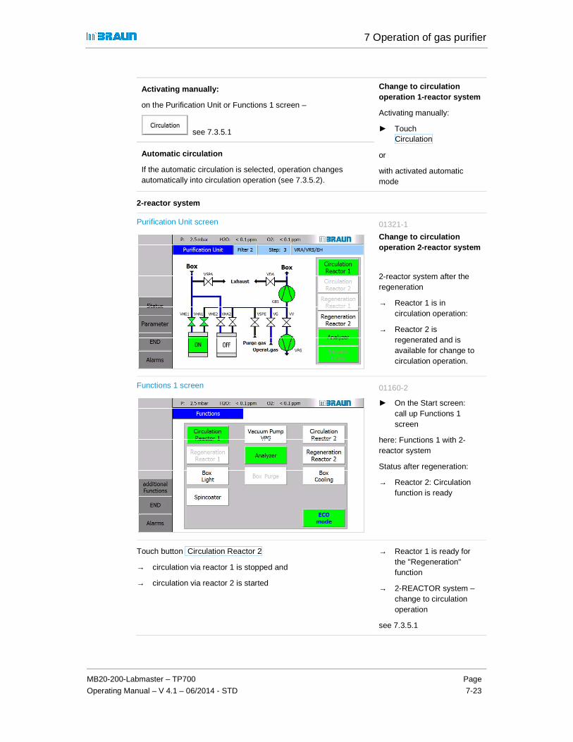
7 Operation of gas purifier
MB20-200-Labmaster – TP700
Operating Manual – V 4.1 – 06/2014 - STD
Page
7-23
Activating manually:
on the Purification Unit or Functions 1 screen –
see 7.3.5.1
Change to circulation operation 1-reactor system
Activating manually:
► Touch Circulation
or
with activated automatic mode
Automatic circulation
If the automatic circulation is selected, operation changes automatically into circulation operation (see 7.3.5.2).
2-reactor system
Purification Unit screen 01321-1
Change to circulation operation 2-reactor system
2-reactor system after the regeneration
→ Reactor 1 is in circulation operation:
→ Reactor 2 is regenerated and is available for change to circulation operation.
Functions 1 screen 01160-2
► On the Start screen: call up Functions 1 screen
here: Functions 1 with 2-reactor system
Status after regeneration:
→ Reactor 2: Circulation function is ready
Touch button Circulation Reactor 2
→ circulation via reactor 1 is stopped and
→ circulation via reactor 2 is started
→ Reactor 1 is ready for the "Regeneration" function
→ 2-REACTOR system – change to circulation operation
see 7.3.5.1

7 Operation of gas purifier
Gas purifier (O2 and H2O)
Page
7-24
MB20-200-Labmaster – TP700
Operating Manual – V 4.1 – 06/2014 - STD
7.3.2.7 Contemporary regeneration of RKM + LMF (optional)
With additional vacuum pump LMF (VPGL)
A simultaneous regeneration is possible if the LMF is equipped with its own vacuum pump (VPGL).
With common vacuum pump (RKM + LMF):
The regeneration of RKM and LMF take place one immediately after the other:
→ The regeneration started first has priority and runs automatically
→ The regeneration started last persists after confirmation of the regeneration gas test in a maintenance step (step 2 of the regeneration programme).
→ That is, only with a delay of 10 hours (MB20/200) is there switching to the next step.
7.3.2.8 After regeneration: empty condensate water container (optional)
After each regeneration:
Empty the condensate water container
► Hold empty vessel under the condensate water container
► Open screw below the condensate water container
► Drain the condensate water
► Seal screw again.

7 Operation of gas purifier
MB20-200-Labmaster – TP700
Operating Manual – V 4.1 – 06/2014 - STD
Page
7-25
7.4 Gas Purifier Solvents (LMF)
Optional equipment internal or standing next to the gas purifier.
7.4.1 Technical Data
Manually-operated LMF - technical data:
Filling: 5 kg active carbon (MBRAUN item no. 2182000)
Suitability: for aromatic and aliphatic as well as halogenated organic solvents; gasoline, kerosene, butyric acid, acid; in other cases the suitability must be checked.
Absorption capability:
approx. 100 g solvent per kg active carbon. The precise quantity depends on the solvent type and the environmental conditions – especially the ambient temperature.
Regenerative LMF - technical data:
Filling: 8 kg Mol sieve (MBRAUN item no. 3240262)
Suitability: for aromatic and aliphatic as well as halogenated organic solvents; gasoline, kerosene, butyric acid, acid; in other cases the suitability must be checked.
Absorption capability:
approx. 100 g solvent per kg mol sieve. The precise quantity depends on the solvent type and the ambient conditions -- especially on the ambient temperature.
! MBRAUN offers sensors that measure the content of the solvent in the gas after it exits the filter. This way, saturation of the solvent filter can be detected early on. Ask MBRAUN Service.
7.4.2 Safety
The solvent filter (LMF) precedes the reactors for H2O and O2 (RKM). In case of incorrect operation, the following risk arises with a manually-operable solvent filter:
WARNING
With the enrichment of solvent vapours in the box atmosphere, reactors and solvent filters, there is a risk of ignition!
If the reactors and the solvent filters are not switched into circulation operation simultaneously, the solvent filter has no effect and there is an enrichment of solvent vapours in the box atmosphere!
With penetration of oxygen into the working area of the system, there is a risk of ignition!
► Always make sure that both solvent filters and the gas purifier are working in parallel in circulation operation.

7 Operation of gas purifier
Gas Purifier Solvents (LMF)
Page
7-26
MB20-200-Labmaster – TP700
Operating Manual – V 4.1 – 06/2014 - STD
7.4.3 Manual valve controlled solvent filter LMF
Circulation operation
If a manually-operated solvent filter is assigned to a gas purifier (H2O + O2 reactor RKM), it can work in parallel to the RKM reactor in circulation operation.
Bypass operation
In bypass operation, the manual valves are set so that the box atmosphere circulates exclusively via the RKM reactors. This operating mode can be selected if no solvents accumulate in the box or for the replacement of the active carbon (see Chapter 12 Inspection and maintenance).
Valve scheme
The following diagram shows the arrangement of the valves that are necessary for the operation of the solvent:
Circulation operation: Bypass operation:
Operation:Gas purifier with solvent filter LMF
Operation:Gas purifier without solvent filter LMF
Valve 1 (V1) open
Valve 2 (V2) open
Valve 3 (V3) close
Valve 3 (V3) open
Valve 1 (V1) close
Valve 2 (V2) close
Valve 4 (V4) must be in the "closed" position.
Valve 4 (V4) must be in the "closed" position.
Maintenance mode for exchange of the active carbon
See valve scheme and description on the system and Chap. 12.5.9 Inspection and maintenance

7 Operation of gas purifier
MB20-200-Labmaster – TP700
Operating Manual – V 4.1 – 06/2014 - STD
Page
7-27
7.4.4 PLC-controlled, regenerative solvent filter LMF
Analogous to the 1 and 2-reactor systems for H2O and O2 (RKM) there are 1 and 2-solvent filter systems (LMF). Solvent filter systems work in parallel to the RKM cleaning units and follow the same functional principle.
! The principle of circulation is the same for 1 and 2-filter systems. Systems with 2 solvent filters can be deployed more flexibly since one filter can be regenerated while the second filter remains active.
7.4.4.1 Overview LMF controller via touch panel
Start screen for system: 2 RKMs and 2 LMFs 01102-2
Display here: separate vacuum pump for LMF (optional)
Navigate to the solvent filter screen
► Touch LMF symbol.
Solvent Filter screen 01402-2
Display here: LMF 1 in circulation operation, LMF 2 in regeneration operation
Solvent Filter screen :
Navigate to the Parameter or Status screen
► Touch navigation button Parameter + Status.

7 Operation of gas purifier
Gas Purifier Solvents (LMF)
Page
7-28
MB20-200-Labmaster – TP700
Operating Manual – V 4.1 – 06/2014 - STD
Solvent Filter Unit Status screen 01400-2
On the screen "Solvent Filter Unit Status:" *)
� Status indicator of the Solvent filter (LMF)
Example: 2-Filter-System
Solvent-Analyzer Parameter + Status screen 01400-3
Display on the screen "Solvent Analyzer Parameter and Status:" *)
� Solvent Filter Analyzer (optional): in Volt
� Parameter alarm setpoint analyzer
see also chapter 7.4.6 Solvent Analyzer
Note:
If no solvent analyzer is available:
→ The navigation button „Analyzer“ in the screens „LMF-1-Filter“ / „LMF-2-Filter“ is shown
→ On the screen Solvent Analyzer Parameter + Status a text field is shown: “Option is not available”
*) Note specifics of operation solvent analyzer without LMF, see 7.4.4.2

7 Operation of gas purifier
MB20-200-Labmaster – TP700
Operating Manual – V 4.1 – 06/2014 - STD
Page
7-29
7.4.4.2 Activate or deactivate regenerable LMF (circulation operation)
Solvent Filter screen - 1-LMF system 01401-2
Activating/deactivating the LMF (1-filter system):
Using the function keys:
- Circulation LMF Filter 1
- Regeneration LMF Filter 1
- Vacuum pump (VPGL) (optional for LMF)
Or: control via Functions 2 screen
Solvent Filter screen - 2-LMF system 01402-2
Activating/deactivating the LMF (2-filter system):
Functions – alternatively Filter 1 or Filter 2:
- Circulation
- Regeneration
- Vacuum pump (VPGL) (optional for LMF)
Or: control via Functions 2 screen
Functions 2 screen 01161
Alternative:
Activating/deactivating operation of the solvent filter via Functions 2 screen
Call up screen with > Start screen > "Functions" navigation button > Functions 1 screen > Navigation button additional functions

7 Operation of gas purifier
Gas Purifier Solvents (LMF)
Page
7-30
MB20-200-Labmaster – TP700
Operating Manual – V 4.1 – 06/2014 - STD
Touch button color changes from WHITE � to GREEN
�
Status LMF from OFF � to ON
Status vacuum pump VPGL for LMF:
The vacuum pump LMF automatically starts operation even if it was not previously activated (for 1 and 2-filter systems)
Activating the circulation LMF:
► Touch button Circulation LMF
→ the function "Regeneration" is blocked
Touch button color changes from GREEN � to WHITE
�
Status LMF from ON � to OFF
Deactivating circulation LMF
► Touch button Circulation
→ the "Regeneration" function of the LMF is ready
! System with two solvent filters (LMF):
If the system is equipped with a second solvent filter, the circulation operation can be switched to the second filter.
In parallel to this, the regeneration can be started for the second filter.
The functional principle is analogous to the O2 / H2O reactors (RKM) - see 7.3.2
7.4.4.3 Regenerate solvent filter
The regeneration of the solvent filter is done according to the same principle as the regeneration of the gas purifying system for O2 and H2O. (See Chap. 7.3.2.3)
Important: The regeneration of the solvent filter is done with pure inert gas (operating gas) - no inert gas/hydrogen mixture may be used! .
! Systems with 1 solvent filter are equipped with a bypass val ve.
This way the solvent filter can be regenerated while the gas only circulates via the H2O/ O2 reactor.
7.4.4.4 Contemporary regeneration of RKM + LMF (optional)
With additional vacuum pump LMF (VPGL)
A simultaneous regeneration is possible if the LMF is equipped with its own vacuum pump (VPGL).
With common vacuum pump:
The regeneration of RKM and LMF take place one immediately after the other:
� The regeneration started first has priority and runs according to programme
� The last regeneration started persists after confirmation of the regeneration gas test in a maintenance step (step 2 of the regeneration programme). That is, that it is only switched with a delay of 10 hours (MB20/200) to the next step.

7 Operation of gas purifier
MB20-200-Labmaster – TP700
Operating Manual – V 4.1 – 06/2014 - STD
Page
7-31
7.4.5 Solvent sensor (Option)
Using a solvent sensor (universal measurement gas sensor (UGP)), it is possible to measure the percentage of solvents in the box atmosphere (Optional: see separate manual UGP).
The measurement values distinguish themselves for the different solvents. Therefore, the value is displayed as a voltage between 0 V and 10 V. The displayed values behave proportionally to the concentration of the solution vapours that are measured after the escape from the solvent filter.
For detection of the capacity limit of a solvent filter (LMF), an additional analyzer can be integrated. This sensor measures the solvent concentration of the circulated gas and generates a warning, if the filter material is exhausted.
! With different solvents, the same alarm limit values can be triggered with different concentrations. Ask MBRAUN Service.
! The display can be adapted to a particular solvent (optional).
Ask MBRAUN Service.
Operation of solvent filters (LMF) with solvent Analyzer
Screen Solvent Filter - 2-LMF-System 01402-2
Analyzer
(5) Navigation button Analyzer
Navigation see 7.4.4.1
Field „Solvent Analyzer“
Screen Solvent Filter – Parameter and Status 01400-2
*)
Display / Parameter Setting solvent analyzer:
Elektrische Spannung (Volt):
� Anzeige Istwert
� Parameter für Alarmschwelle

7 Operation of gas purifier
Gas Purifier Solvents (LMF)
Page
7-32
MB20-200-Labmaster – TP700
Operating Manual – V 4.1 – 06/2014 - STD
Operation of Solvent Analyzer - without Solvent Filter (LMF)
Menue Screen Selection 01120-1
On the screen “Menue Screen Selection”:
If the system is not equipped with an LMF, an additional button Solvent Analyzer is optionally available:
Call up the screen “Solvent Filter Parameter and Status”:
► Touch the button Solvent-Analyzer
8 Operation of the inert gas box
MB20-200-Labmaster – TP700
Operating Manual – V 4.1 – 06/2014 - STD
Page
8-1
8.1 Introduction ...................................... ......................................................8-2
8.2 Safety ............................................ ..........................................................8-2 8.2.1 In normal operation ................................................................................................ 8-2 8.2.2 In case of error / In case of improper operation ...................................................... 8-3
8.3 Basic principles for safe work with the inert gas b ox .........................8-5 8.3.1 Media connections ................................................................................................. 8-5 8.3.2 Heed openings of the box ...................................................................................... 8-5 8.3.3 Avoid material damage and leaks .......................................................................... 8-5 8.3.4 Maintain inert gas atmosphere in the box ............................................................... 8-8 8.3.5 Working with the box's gloves ................................................................................ 8-9 8.3.6 Making box ready for operation ............................................................................ 8-11
8.4 Basic principles of sensor monitoring of the inert gas atmosphere 8-13 8.4.1 Display of the measurement values ..................................................................... 8-13 8.4.2 PLC: activate/deactivate measurement devices ................................................... 8-15
8.5 Operation of the inert gas box .................... ........................................ 8-18 8.5.1 Manual purging of the box .................................................................................... 8-18 8.5.2 Controlling box pressure and atmosphere ............................................................ 8-23 8.5.3 Activate/deactivate box-related functions ............................................................. 8-27 8.5.4 Box during circulation operation ........................................................................... 8-28 8.5.5 Box during regeneration operation ....................................................................... 8-31 8.5.6 Box purge (optional) ............................................................................................. 8-32
8.6 Customer's applications in the p gas box .......... ................................ 8-38
8.7 Additional functions and box equipment (optional) . ......................... 8-39 8.7.1 Additional box equipment (optional) ..................................................................... 8-39 8.7.2 Box safety equipment (optional) ........................................................................... 8-40
8 Operation of the inert gas box
Introduction
Page
8-2
MB20-200-Labmaster – TP700
Operating Manual – V 4.1 – 06/2014 - STD
8 Operation of the inert gas box
8.1 Introduction
The inert gas box allows the processing of materials that are sensitive to oxygen and moisture in the box. This function is secured by the set-up of the system and the controller. However, there are risks in case of error and due to incorrect operation if ambient air penetrates the box or inert box atmosphere penetrates outside and process materials come into contact with oxygen.
The quality of the box atmosphere in a closed system is ensured by adherence to the operational flows (see also antechamber processes).
The safety of the system depends entirely on the leak tightness of an undamaged box.
With this goal, safety instructions and basic rules for safe work with the inert gas box are provided here.
8.2 Safety
8.2.1 In normal operation
Pressure
Under normal operating conditions, a standard inert gas box is designed for a maximum interior pressure between -15 mbar and + 15 mbar (- 1500 Pa and + 1500 Pa).
Particular exceptional situations such as malfunctions of valves or components can cause extreme pressure situations in the inert gas box. At a pressure of approx. +/- 20 mbar (+/- 2000 Pa), the gloves separate from the feedthroughs.
In case of error, this type of pressure release for the box is only permissible if harmless gases and process materials are used.
Depending on the type of gases and process materials used, additional equipment may be necessary (See below).
Ambient air
At commissioning or after maintenance work, the box is filled with ambient air. Please note:
NOTICE
Circulation operation with ambient air in the box can damage the reactor medium and O2 and H2O sensors! Depending on the process materials, unknown risks may arise!
In case of an O2 percentage in the box atmosphere of more than 100 ppm:
o Purge box with inert gas until there is an O2 percentage in the box atmosphere less than 100 ppm
Follow the instructions "Manual purging of the box" in Chapter 8.5.1

8 Operation of the inert gas box
MB20-200-Labmaster – TP700
Operating Manual – V 4.1 – 10/2014 - STD
Page
8-3
8.2.2 In case of error / In case of improper operation
Risk of suffocation in case of error / in case of improper operation
DANGER
Risk of suffocation in case of improper operation!
Opening of an inert box and large leaks can create a risk of suffocation, especially if the on-site conditions are not fulfilled!
� Never stick your head into an inert antechamber/box!
► Always ensure good ventilation of the room!
► Make sure that flanges on the box are always sealed to the outside
► In case a glove tears, replace the glove immediately
Before opening the pane/box:
► Exchange the inert box atmosphere for ambient air!
► Open the box only after the oxygen content is > 19.5 %
Follow the instructions in Chapter 11, Troubleshooting and Chapter 12, Maintenance (glove replacement).
Risk of suffocation with permanently-active automatic box purging
DANGER
With permanently-active automatic box purging with inert gases: risk of suffocation
Risk of suffocation due to escaping inert gases in case of error (such as open flange, glove tear)! There can be a permanent gas escape into the ambient air and this can endanger life and health!
► Make sure that the parameter for the "Automatic switch-off" function is activated if there is no operator at the system
► Follow the description in this operating manual!
If the system is equipped with automatic box purging (optional) - see also Chap. 8.8

8 Operation of the inert gas box
Basic principles for safe work with the inert gas box
Page
8-4
MB20-200-Labmaster – TP700
Operating Manual – V 4.1 – 06/2014 - STD
Damage due to extreme pressure circumstances
Extreme pressure circumstances can arise due to malfunctions of valves or additional components. The degree of hazard depends
� on the gases and process materials used (see below Chap. 8.2.2.2).
� on the on-site conditions - in case they are not met!
DANGER
In case of error, extreme pressure circumstances can cause glove tears and risk of suffocation!
► Eliminate cause of the extreme under/over pressure
► Replace the gloves quickly -
While so doing never seal all gloveport feedthroughs with covers!
► Leave at least one gloveport feedthrough unsealed!
8.2.2.1 When using non-harmful gases/process materials
Under the assumption that only non-harmful gases and process materials are used, in case of error with extreme pressure circumstances (> 20 mbar) the gloves come off of the feedthrough. Therefore in the standard system there is a burst guard for the box.
NOTICE
In case of damage to the box/gloves of the box or in case of error (e.g. open flange): penetrating ambient air can damage sensitive process materials
► Eliminate the cause of the damage
► Check process materials/products for damage
► Before re-commissioning: purge the box atmosphere
(See also behaviour in case of over/under pressure of the box: Chap. 11, Troubleshooting).
8.2.2.2 Use of hazardous process materials
Standard systems (category 0) offer no personal protection! They are not properly designed for the use of health and environment-threatening process materials (category I-IV and EX).
DANGER
When using hazardous process materials
► Follow the instructions in the basic safety chapter for the classification and evaluation of substances (Chapter 3)
► If necessary, ensure the application of the required additional equipment such as box pressure fuse, adherence to the O2 values and exhaust disposal!
► If necessary, please contact MBRAUN Service

8 Operation of the inert gas box
MB20-200-Labmaster – TP700
Operating Manual – V 4.1 – 10/2014 - STD
Page
8-5
8.3 Basic principles for safe work with the inert gas box
To maintain the inert gas atmosphere in the box and prevent the above-mentioned risks: at interfaces to the system, pay particular attention to:
8.3.1 Media connections
� Install properly
� Heed status of the valves
� Flange (optional)
� Always note that these e.g. after uncoupling of a media connection, must be sealed to the outside immediately
8.3.2 Heed openings of the box
Antechamber doors:
� Only open inner antechamber door if the antechamber atmosphere matches the box atmosphere and the outer antechamber door is closed
Quick-closures on box panes (optional):
� Only open for service purposes if the box is filled with ambient air and the oxygen content is > 19.5 %.
Gloveport feedthroughs
� (see below)
8.3.3 Avoid material damage and leaks
Material damage can be caused mechanically, chemically or by the influence of (UV/laser) radiation. Please heed the following notes:
Avoid extreme pressure increases/drops
Particular exceptional situations such as malfunctions of valves or components can cause extreme pressure situations in the inert gas box.
Prerequisite: no hazardous process materials/processes are used
At a pressure of approx. +/- 20 mbar (+/- 2000 Pa), the gloves separate from the feedthroughs. This causes pressure release in the box, thus preventing breakage of the box panes - however only if at least one gloveport feedthrough is not sealed with a cover.

8 Operation of the inert gas box
Basic principles for safe work with the inert gas box
Page
8-6
MB20-200-Labmaster – TP700
Operating Manual – V 4.1 – 06/2014 - STD
Manual valves in standard operation:
� Heed valve position gas input/gas output:
Commissioning: 1. Open box output valve 2. Open box input valve
Decommissioning: 1. Close box input valve 2. Close box output valve
Particle filter of the box:
� Heed degree of saturation / differential pressure (see Chap. 8.4.4) and replace particle filter of the box in timely fashion.
Using additional equipment if necessary for pressur e regulation:
� Over pressure securing of the box
� Automatic box purge function
� If necessary to secure pressure regulation if additional components that influence pressure are used in the box: (such as spin coater, particle absorber, feedthroughs for gas feed from external source directly into the box (etc.)
� Processes that generate high temperatures influence the box pressure; box cooling may be necessary.
� If safety equipment for pressure regulation and monitoring is installed: - never operate the system without safety equipment/alarm equipment - regularly check the functionality of the safety equipment (see Chap. 8 A, 10 ...)
Avoid mechanical effects from moving parts:
With the use of moving parts in the box (customer's equipment):
� Monitoring of the movement with light barriers, automatic stop,
� emergency off
If using pneumatic parts: risk of ejecting material
� Regular inspection and maintenance of pneumatic equipment
Chemical effects on materials
Make sure that the process materials used meet the specification of the material of the seals and gloves. Ask MBRAUN Service.
� If necessary, use a gripper tool
� Clean the sealing material/gloves carefully after contact with aggressive chemicals
Recommendation: with use of solvents in the box:
� Use of solvent removal filters and solvent sensors (see Chap. 7.4 Gas purifier solvent filters)

8 Operation of the inert gas box
MB20-200-Labmaster – TP700
Operating Manual – V 4.1 – 10/2014 - STD
Page
8-7
Minimise temperature effects (� gloves )
Damage due to contact with hot surfaces:
With use of temperature-influencing additional equipment (freezer, heating plate, etc.), material ageing or damage to gloves and seals can arise:
� Wait before direct contact until the material has reached the ambient temperature
� If necessary, use a temperature-resistant gripper tool
� Follow the operating instructions for the special components
Influence of temperature on the pressure in the box (see above)
Protect material against effects of radiation
If using additional equipment/radiation-intensive processes:
UV light / laser
� Keep gloves out of the direct radiation area
� Check material of the gloves and seals regularly for damage
Reduce particle content in the box
In case of intensive particle formation in the box, MBRAUN recommends additional equipment:
� Differential pressure monitoring (optional)
In case of additional equipment/particle-intensive processes in the box:
� Heed degree of saturation of the particle filters of the box: saturated particle filters reduce the gas flow and increase the differential pressure of the blower
8 Operation of the inert gas box
Basic principles for safe work with the inert gas box
Page
8-8
MB20-200-Labmaster – TP700
Operating Manual – V 4.1 – 06/2014 - STD
8.3.4 Maintain inert gas atmosphere in the box
All (PLC-controlled) processes – such as circulation, antechamber processes - are aimed at maintaining a defined inert gas atmosphere in the box.
Prerequisite
� Purging of the box (see Chap. 8.5.1 Manual purging of the box)
For the measurement accuracy of the sensors, heed:
The controller works on the basis of the measurement values of the sensors (see also Chap. 8.4). Therefore always note:
� Switching of the sensors and switching on of the circulation only after reaching an O2 concentration < 100ppm
� Adhere to cleaning and calibration cycles: H2O sensors (MB-MO-SE1)
� Adhere to calibration cycles: O2 sensors (MB-OX-SE1)
With use of additional sensors with own power supply (optional):
Please note:
� that the sensors are switched on
� that the valves are open and the measurement cells are in the gas stream
In case of interruption of the circulation, note:
In a box that is not in circulation operation, the O2 and H2O content constantly increase
� Keep box in circulation operation
� in case of longer interruption of the circulation: remove O2 and H2O-sensitive materials from the box or seal them safely in a container

8 Operation of the inert gas box
MB20-200-Labmaster – TP700
Operating Manual – V 4.1 – 10/2014 - STD
Page
8-9
8.3.5 Working with the box's gloves
The operator reaches into the box with the gloves in order to move materials in the box, execute process flows and operate the antechamber doors from inside.
Standard boxes are equipped with round gloveport feedthroughs and butyl gloves.
! Always wear cotton gloves in the gloves in the box.
NOTICE
Material damage and material ageing of the box's gloves due to particular materials and processes
► Check whether the gloves are suitable for the specification of your processes/process materials
► If necessary, use additional protection such as gripper tool, temperature guard
► Prevent damage to the gloves - due to sharp, pointy objects - due to rotating objects
► Avoid exposure to UV rays (laser) - extreme temperatures
► In case of damage to the gloves, ambient air penetrates the box, disturbs the inert gas atmosphere and can damage process materials and processes in the box.
A leak in the gloves is indicated, e.g. by a pressure drop and unstable O2 and H2O values in the box.
► Check the material of the gloves
If the system is equipped with an automatic function box purge, � an error message appears on the touch panel (See Chap. 11).

8 Operation of the inert gas box
Basic principles for safe work with the inert gas box
Page
8-10
MB20-200-Labmaster – TP700
Operating Manual – V 4.1 – 06/2014 - STD
! For the case that a glove change is required during ongoing operation:
► Practice behaviour in case of error and in case of glove replacement regularly(See Chapter 11, Troubleshooting and your operation-specific standard operating manual as well as Chapter 12, Maintenance)
► Always keep appropriate spare gloves for the box at the ready (see Chap. 13, Spare parts list)

8 Operation of the inert gas box
MB20-200-Labmaster – TP700
Operating Manual – V 4.1 – 10/2014 - STD
Page
8-11
8.3.6 Making box ready for operation
Check at start of work/beginning of the week *)
Pow
er
supp
ly/s
witc
h on
Fun
ctio
n on
th
e pa
nel
Val
ve c
heck
:
open
Vis
ual
insp
ectio
n of
se
tting
s
ECO-Mode (optional)
x OFF
Media supply
Operating gas X Through-flow (pressure reducing valve)
Regeneration gas Gas quantity X
Gas output to gas purifier
X
Gas output to exhaust air
Electrical system
Gloves Material
Seals Material
Sensors (box + pipework)
x ON
H2O x ON
O2 x ON
UGP (optional) X x ON X
GSU (optional) X x ON X
H2 / other (optional)
X x ON X X
Additional components in the box
Spincoater, particle absorber
Stand-alone: (x)
x ON X
Electrical system X
Cooling water X
Box warning equipment (optional)
X
opto-acoustic X

8 Operation of the inert gas box
Basic principles for safe work with the inert gas box
Page
8-12
MB20-200-Labmaster – TP700
Operating Manual – V 4.1 – 06/2014 - STD
Pow
er
supp
ly/s
witc
h on
Fun
ctio
n on
th
e pa
nel
Val
ve c
heck
:
open
Vis
ual
insp
ectio
n of
se
tting
s
Safety equipment (optional)
X
Light curtain X
Securing the system (nights, weekends)
In case of interruption of circulation operation:
► Remove sensitive materials from the box and secure
► Activate ECO-Mode (optional)
see Chap. 6 A.

8 Operation of the inert gas box
MB20-200-Labmaster – TP700
Operating Manual – V 4.1 – 10/2014 - STD
Page
8-13
8.4 Basic principles of sensor monitoring of the inert gas atmosphere
In standard systems,there is generally a measurement of the oxygen and moisture content of the box atmosphere (optional equipment).
! The sensors MB-OX-SE1 and MB-MO-SE1 are described in separate documentation.
For special requirements, additional measurement sensors can be used (optional)
� e.g. a universal gas measurement probe (UGP) for the use of solvents
� For the integration of measurement sensors into the PLC: additional display of the measurement value on the touch panel;
� or special display on the separate combi monitor
see additional chapter 10 A ff. and supplier documentation
8.4.1 Display of the measurement values
Box pressure, H2O and/or O2 measurement values are displayed on the touch panel. If additional sensors are used (optional: solvents, helium, N2, etc.) there is an additional display.
Measurement ranges (standard)
Oxygen sensor MB-OX-SE-1 0.. 1000 ppm
Moisture sensor: MB-MO-SE-1 0.. 500 ppm
Display of the measurement values
The measurement values are displayed on the permanent line and on the start screen:
Display of the measurement values on the permanent line on each screen (exception: start screen, see below)

8 Operation of the inert gas box
Basic principles of sensor monitoring of the inert gas atmosphere
Page
8-14
MB20-200-Labmaster – TP700
Operating Manual – V 4.1 – 06/2014 - STD
Start screen 01103-1
Display measurement values of the box atmosphere (pressure, H2O, O2 etc.)
(see Chap. 5)
Display constellations:
No sensor configured
Sensor switched off
Sensor defective
Operating indicator
Dependencies H2O sensor – O2 sensor
The H2O sensor is only switched on � if the O2 concentration in the box is <999.9 ppm
(see also: Chap. 6, Operating modes, commissioning)

8 Operation of the inert gas box
MB20-200-Labmaster – TP700
Operating Manual – V 4.1 – 10/2014 - STD
Page
8-15
8.4.2 PLC: activate/deactivate measurement devices
Please note:
If separate measurement devices with their own power supply are used:
► Switch device ON� only then can there be an activation via the PLC
Functions 1 01160-1
Variant 1:
Functions screen
Gas purifier 01310-2
Variant 2:
Purification Unit screen
Switching on
► Touch button Analyzer
The colour of the function key changes from WHITE � to GREEN
Switching off
► Touch button Analyzer again
The colour of the function key changes from GREEN � to WHITE

8 Operation of the inert gas box
Basic principles of sensor monitoring of the inert gas atmosphere
Page
8-16
MB20-200-Labmaster – TP700
Operating Manual – V 4.1 – 06/2014 - STD
Please note:
The sensors are switched OFF automatically after 30 minutes if the box is not in operation -- that is, neither circulation nor box purging are active.
This serves to protect the measurement cells that should always be purged with box gas.
Securing measurement precision
! The operation of the sensors with an oxygen content greater than 1000 ppm (e.g. in air) must be avoided.
After an exposure to the ambient air, it can take several hours until the sensor provides accurate measurement values about inert gas conditions again.
Calibration of the measurement devices
MBRAUN measurement devices are calibrated at the factory before delivery.
The calibration cycles depend on the use of the measurement devices and the gases used (purity, trace gases, etc.).
! It is recommended that you have the measurement devices calibrated once a year by MBRAUN specialized personnel. Please use the included decontamination explanation in Chap. 12.
► For more information, please contact MBRAUN Service.
Moisture sensor MB-MO-SE1
! In order to achieve optimal measurement results, the sensor element MB MO-SE-1 should be cleaned routinely every three months or at the latest after 2000 hours of operation.
! Insufficient maintenance of the moisture sensor causes imprecise measurements and compromises the cleanliness of the box atmosphere, after 2000 hours of operation a cleaning of the sensor is necessary!
► Clean the moisture sensor at the latest when asked to do so by the warning message (96).

8 Operation of the inert gas box
MB20-200-Labmaster – TP700
Operating Manual – V 4.1 – 10/2014 - STD
Page
8-17
Clean moisture sensor, reset operating hours
Call the screen Service H2O-Sensor from the General Parameters screen.
Service Moisture Analyzer 01705
"Operating hours" field
Enter value "0" in the "Operating hours" field or:
► Touch button Reset
If more frequent maintenance should be conducted, the parameter "2000 Operating hours" can also be reduced.

8 Operation of the inert gas box
Operation of the inert gas box
Page
8-18
MB20-200-Labmaster – TP700
Operating Manual – V 4.1 – 06/2014 - STD
8.5 Operation of the inert gas box
8.5.1 Manual purging of the box
Note: Analyzers will not read accurately during manual purging of the box. They will typically read a false low value If the box contains ambient air – such as on commissioning, after service work or in case of disturbances (leaks, glove tear) – the box must be purged. Only if the remaining oxygen content has a value of less than approx. 100 ppm is the box prepared for the switching on of the sensors and for the change to circulation operation (see above, sensor monitoring and Chap. 7.3.2).
NOTICE
Damage to the sensors and the reactor medium due to O2 and H2O in the ambient air!
Circulation operation in ambient air can cause overheating of the reactor material and destruction of the valves and damage to the O2 and H2O sensors.
If ambient air gets into the box:
o Purge box with inert gas from external source until there is an O2 percentage in the box atmosphere of less than 100 ppm
Note: Manual purging is not a standard feature on Labmaster and MB20/MB200 systems. See section 8.5.6 for directions on using the automatic box purge feature
The external purging can take place in two ways:
� Manual purging. In standard operation the purging of the box with operating gas of medium purity from external source (e.g. bottle supply). This procedure is described below.
� PLC-controlled purging via the manual or automatic box purge function (Optional: see Chap.8.5.6 Purging the box)
Prerequisites for the manual purging of the box:
WARNING
Risk of suffocation if the on-site conditions were not adhered to!
If the on-site conditions cannot be adhered to:
► Divert used purging gas via an in-house exhaust air system!
o the installation is complete (see Chap. 4)
o All antechamber doors are closed
o Equipment components in the box are switched off
o Controller - touch panel: the system functions "regeneration" and "circulation" are switched off
Pay special attention to all areas of the box in which there are not many gas movements (corners and areas surrounding installed equipment), especially
open sealed room areas and purge them (e.g. storage containers, equipment such as freezer,

8 Operation of the inert gas box
MB20-200-Labmaster – TP700
Operating Manual – V 4.1 – 10/2014 - STD
Page
8-19
spincoater, etc.).
Action sequence manual purging of the box with a Ma nual Purge Valve
Step ► Action at gas source ► Box Operation
1 Set upper working pressure to 14 mBar
Ser lower working pressure to 10 mBar
Return to home screen
2 Check purge gas quantity:
approx. 10 - 12 m3 per 1 m3 box volume
(3-4 cylinders per 1 m3 box volume)
A standard two glove Unilab is approximately 0.8 m3
3 Switch installed components (refrigerator, drying oven, etc.) in the box OFF;
4 Ensure pressure increases to 10-14mbar Ensure pressure increases to 10-14mbar
5
Open Valve on top of box
(valve shown in closed position)
6 Allow ~3 tanks to purge for a two glove Unilab box.
Turbulating the atmosphere with a fan or by waving the gloves will reduce the amount of gas need.
7 Close Valve on top of box
8 Set pressure back to normal working setpoints
Typical:
Upper working limit 5 mBar
Lower working limit 0.5 mBar
9 If system is equipped with analyzers turn analyzers on and allow reading to stabilize
10 Turn Circulation on. If level spikes above 100PPM stop circulation and resume purging

8 Operation of the inert gas box
Operation of the inert gas box
Page
8-20
Action sequence manual purging of the box with a hose
Step ► Action at gas
1 Provide purge as supply equipment (e.g. bottle) with pressure reducing valve.
2 Check purge gas quantity:
approx. 10 - 12 m
3
4 Connect gas hose to purge gas supply.
5 Set pressure reducing valve to 3and open.
6
7
8
9
10 After through-quantity:
Close gas source
11
12
13
Operation of the inert gas box
Operation of the inert gas box
MB20-200-Labmaster
Operating Manual – V 4.1 –
Action sequence manual purging of the box with a ho se
Action at gas source ► Handling in the box (with fixtures)
Provide purge as supply equipment (e.g. bottle) with pressure reducing valve.
Check purge gas quantity:
12 m3 per 1 m3 box volume
Switch installed components (refrigerator, drying oven, etc.) in the box OFF;
Connect gas hose to purge gas supply.
Set pressure reducing valve to 3-5 bar
Remove blind flange on the rear side of the box.
Insert gas hose into the box through the open flange.
Use gloves to reach gas hose intobox and purge the inside of the box from top to bottom with circular motions. Purge intermediate areas, corners, edges carefully.
Installed equipment with closed areas (refrigerators, drying ovens) etc.)
Open interior space:- match temperature to room temperature (e.g. in case of ovens, refrigerator)
- Purge interior space carefully
-flow of the calculated gas
Close gas source
Remove gas hose from the box while so doing, cover the flange opening with a flat hand
Close opening immediately with blank cap on the rear side of the box
If system is equipped with analyzers turn analyzers on and allow reading to stabilize
Labmaster – TP700
– 06/2014 - STD
Handling in the box (with fixtures)
Switch installed components (refrigerator, in the box OFF;
Remove blind flange on the rear side of
Insert gas hose into the box through the
Use gloves to reach gas hose into the box and purge the inside of the box from top to bottom with circular motions. Purge intermediate areas, corners, edges
Installed equipment with closed areas (refrigerators, drying ovens) etc.)
match temperature room temperature (e.g. in case of
Purge interior space carefully
Remove gas hose from the box – and while so doing, cover the flange opening
Close opening immediately with blank cap on the rear side of the box
If system is equipped with analyzers turn analyzers on and allow reading to
8 Operation of the inert gas box
MB20-200-Labmaster – TP700
Operating Manual – V 4.1 – 10/2014 - STD
Page
8-21
Step ► Action at gas source ► Handling in the box (with fixtures)
14 Turn Circulation on. If level spikes above 100PPM stop circulation and resume purging

8 Operation of the inert gas box
Operation of the inert gas box
Page
8-22
MB20-200-Labmaster – TP700
Operating Manual – V 4.1 – 06/2014 - STD
Systems with measurement devices: checking the oxyg en content in the box
For systems equipped with the oxygen measuring device MB-OX-SE1 (O2 sensor) :
After the purging: Determine O2 value :
Step Prerequisite Action: touch panel: Action: Box
> The action sequence "manual purging" is carried out
1 Through-flow of approx. 5 m3 purging gas per 1 m3 box volume
[Multi-box system: switch box on]
Switch circulation ON: establish slight over pressure
2 Switching measurement devices on (Functions screen)
3 Observe display of O2 value.
4 Display O2 value: - within approx. 10 sec. a declining tendency and
- O2 < 100 ppm
Prerequisite is not fulfilled:
Switch circulation OFF
5 Repeat: sequence manual purge for approx. 2 minutes (see above steps 4 to 12)
6 Display O2 value: - within approx. 10 sec. a declining tendency and
- O2 < 100 ppm
Prerequisite is fulfilled:
The normal operating state is reached – continue the "Circulation" function

8 Operation of the inert gas box
MB20-200-Labmaster – TP700
Operating Manual – V 4.1 – 10/2014 - STD
Page
8-23
Systems with 2 measurement devices: oxygen sensor M B-OX-SE1 and moisture sensor MB MO-SE-1
The switching on of the moisture sensor is done depending on the oxygen sensor:
Step Prerequisite Controller
1 Oxygen sensor:
O2 concentration in the box is < 999.9 ppm
The moisture sensor MB-MO-SE1 is switched on
8.5.2 Controlling box pressure and atmosphere
8.5.2.1 Overview of parameters
The table in Chapter 5.6 Pre-set parameters provides an overview of the pre-set parameters for a standard system.
8.5.2.2 Parameters for the box
Navigating with the Menue Screen Selection
Menue Screen Selection 01120-1
Selection of box-related parameters:
� Box pressure � Box atmosphere
� Temperature (box cooling, freezer – optional)
� Box purge (optional)
� Solvent Analyzer (optional, if no solvent filter is integrated to the PLC – s. chapt. 7.4.4.2)

8 Operation of the inert gas box
Operation of the inert gas box
Page
8-24
MB20-200-Labmaster – TP700
Operating Manual – V 4.1 – 06/2014 - STD
Box pressure parameters 01500-2
Input of parameters:
► Touch numeric field:
► Input is done using the alphanumeric field
The basic principles for the function of pressure regulation are described in Chap. 2.3.3.
Operational limits – setting alarm limits:
> The value of the upper operational limit must be less than the value of the upper alarm limit,
> The value of the lower operational limit must be greater than the value of the upper alarm limit.
Upper and lower alarm limit
> Setting only by MBRAUN Service
Parameters for box atmosphere (O2 and H2O)
Parameters for box atmosphere (O2 and H2O) 01500-1

8 Operation of the inert gas box
MB20-200-Labmaster – TP700
Operating Manual – V 4.1 – 10/2014 - STD
Page
8-25
Temperature parameter
Temperature parameter (freezer / box cooling) 01590-1
! The input fields are only active if the system is equipped with the appropriate components. If not, then "not present" is indicated in the input field.
! Settings and functions of freezer and box cooling:
see separate Chapter / Documentation 10 A. ff and Chap. 15 Supplier documentation.
Temperature Target value Actual value
Box cooling 10°C to 40°C see display
Freezer -35°C to 10°C see display
Purge box parameters (optional)
See below, Chap. 8.8 Box purging, PLC-controlled

8 Operation of the inert gas box
Operation of the inert gas box
Page
8-26
MB20-200-Labmaster – TP700
Operating Manual – V 4.1 – 06/2014 - STD
8.5.2.3 Inert gas atmosphere trends
The course of the oxygen and moisture content and of the box pressure is displayed on the following screen:
Box Trend Curves 01502
Navigation: Menue Screen Selection > Box Trend Curves
→ Display of the current course of H2O, O2 and box pressure:
Display of course over 24 hours:
► Touch button 24h
Shift time axes: see Chap. 5.3.6

8 Operation of the inert gas box
MB20-200-Labmaster – TP700
Operating Manual – V 4.1 – 10/2014 - STD
Page
8-27
8.5.3 Activate/deactivate box-related functions
Functions 1 screen 01160-1
The box-related functions are switched ON and OFF using the "Functions 1" screen:
► Touch the button in question:
Switch the box light on/off
Switch measurement devices (O2 and H2O) on and off
Switch circulation function on/off
See also Chap. 8.5.6 Purging the box
Box is in operation: circulation here via reactor 1 see also Chap. 7 Gas purifier
Alternatively: Automatic “Box Purge” or Manual Purge – see 8.5.6
Switch the "Automatic box purge" function on and off Example above: the function is blocked since the circulation function is active
Alternatively: Box Purge or Manual Purge – see 8.5.6
Switch "Manual box purge" function on and off
Switch "Box cooling" function on/off
Integrated additional components (optional) – function as autonomous units, are activated/deactivated via the touch panel:
here: Spincoater
Switch on the off the additional components that are used in the box

8 Operation of the inert gas box
Operation of the inert gas box
Page
8-28
MB20-200-Labmaster – TP700
Operating Manual – V 4.1 – 06/2014 - STD
8.5.4 Box during circulation operation
The basic principles of circulation operation are described in Chapter 7 Gas purifier.
For the operation of the box, please heed the following peculiarities with respect to the management of the box atmosphere
8.5.4.1 Distinctions 1- and 2-reactor systems
1-RKM system
In circulation operation, the box atmosphere circulates between the box and gas purifier. The O2 and H2O content of the box atmosphere is monitored by sensors (optional) and a stable box atmosphere is maintained according to the parameters set.
The circulation is switched off during the course of the regeneration programme and the function blocked. It can only be activated again after completion of the regeneration programme.
1-RKM with automatic circulation
If the automatic circulation is switched on, the circulation starts automatically after completion of the regeneration programme (see Chap. 7.3.1.2).
2-RKM system
A 2-RKM system allows continuous processes in the box since one purifier unit apiece is in circulation operation, while the other is being regenerated or is in stand-by mode. A stable box atmosphere is thus guaranteed without interruption.
Blocked functions
During circulation operation of a purifier unit, the following functions are blocked:
� "Regeneration" function
� "Purge box" function
See Chap. 7.3.2
NOTICE
Process materials can be compromised if the circulation is switched off since the degree of purity of the box atmosphere declines proportionately over time.
Process materials that require great purity of the box atmosphere
► secure in a container that can be sealed
► remove from the box

8 Operation of the inert gas box
MB20-200-Labmaster – TP700
Operating Manual – V 4.1 – 10/2014 - STD
Page
8-29
8.5.4.2 Pressure regulation and monitoring
For normal operation, the box pressure is PLC-regulated in a defined range.
Status box pressure – Status gloves
The status of the box pressure can be determined from the status of the gloves:
Over pressure: gloves directed to the outside
Under pressure: gloves directed to the inside
Display on the touch panel
Display of measurement values
on the Start screen
on the permanent line
PLC-regulated pressure monitoring
With the defined parameters, the pressure regulation is set within the operating limits and the gas feed/gas removal is regulated.
For functioning of the pressure regulation: see Chapter 2.3.3 Setting the parameters for the operating limits, hysteresis and alarm limits: see 8.6.2
Detection of open pane or glove tear.
If on activation of one of the two valves VG/VV after a delay time a defined pressure increase or pressure drop ramp is not achieved, then an error message "Box open or glove tear" is displayed on the panel.
This monitoring is only active in the pressure range ≥ + 2mbar and ≤ - 2 mbar (- 2 mbar ≥ P ≥ + 2 mbar).
Settings on the panel may only be made by MBRAUN Service.

8 Operation of the inert gas box
Operation of the inert gas box
Page
8-30
MB20-200-Labmaster – TP700
Operating Manual – V 4.1 – 06/2014 - STD
Setting pressure with the foot switch
By pressing the foot switch, it is possible to adapt the pressure in the inert gas box within the defined operating range as needed (see 2.3.3.3).
Reduce pressure:
► Press left foot pedal.
Increase pressure:
► Press right foot pedal.
! The activation time of the foot switch is limited to 7,5 sec, due to safety aspects. Afterwards, actuate the foot switch again.
Keep pressure constant in case of reaching into the gloves of the box:
If you want to reach into the gloves in a box with positive box pressure:
► first reduce pressure slightly.
If you remove your hands from the gloves:
► increase pressure slightly
Mechanical securing box over pressure
Replacing the gloves
WARNING Only permitted with use of non-harmful process materials/process gases
In case of error (e.g. defective valve) and increase of box pressure to > 20mbar:
→ The gloves separate from the gloveport feedthrough.
→ Thus the box/box pane are protected against rupture (see also Chap. 11 - Behaviour in case of error)
Securing of box over pressure via pressure control valve (optional)
WARNING With use of sensitive process materials (product protection) or process materials/process gases that could harm health or the environment (personal protection), additional safety equipment such as the following is necessary
� Box pressure control valve (optional)
� and connection to an in-house exhaust system (optional)
See also optional additional chapter 8 A.

8 Operation of the inert gas box
MB20-200-Labmaster – TP700
Operating Manual – V 4.1 – 10/2014 - STD
Page
8-31
8.5.5 Box during regeneration operation
The basic principles of regeneration operation are described in Chapter 7 Gas purifier. For the operation of the box, please note the following peculiarities:
1-reactor system (RKM)
For systems with one reactor, there is no gas purification process during regeneration and the quality of the box atmosphere declines proportionately with time.
Recommendation
During regeneration, processes in the box should only be continued if non-sensitive materials are used.
Otherwise regeneration should, if possible, be done after the end of a work day overnight so that on the next day the required quality of the box atmosphere in circulation operation is available.
2-reactor system (RKM)
In the 2-reactor system, 1 reactor apiece is in circulation and 1 reactor is in regeneration operation. This guarantees a stable box atmosphere. Processes in the box can be carried out without interruption.
1- or 2-reactor system (RKM) and solvent removal fi lter (LMF)
NOTICE
Solvent vapours attack the sealing material of the box panes and antechambers and damage the reactor medium of the H2O and O2 reactors.
Manual LMF:
With use of solvents in the box, it must be heeded that the solvent filter is always switched on (required for manual LMF) - (see Chap. 7.4).
Automatic LMF
An automatic LMF is switched on PLC-controlled.
Recommendation
If there is a high concentration of solvent vapours due to processes in the box and/or continuous processes in the box are necessary:
► Work with a 2-filter LMF system where 1 reactor can work in circulation and 1 in regeneration operation
► If necessary use a solvent sensor (UGP)
Please contact MBRAUN Service.

8 Operation of the inert gas box
Operation of the inert gas box
Page
8-32
MB20-200-Labmaster – TP700
Operating Manual – V 4.1 – 06/2014 - STD
8.5.6 Box purge (optional)
For the purging of the box with direct feed of inert gases, there are optionally 3 different functions available that are controlled via the touch panel:
Function Description Valves Chapter
Manual purge � Function is included by default with
equipment with ECO-Mode
� Systems without ECO-Mode: optional
VG + VDA 8.5.6.1
Purge box
MB-BS-200-PLC � Optional function VSE + VSA 8.5.6.2
Automatic box purge
Prerequisite: equipment of the system with MB-BS-200-PLC;
� Automatic is set and activated/deactivated using parameters
8.5.6.3
Purging the box:
Typically the Labmaster or MB20/MB200 will include an automatic purging feature. And manual purging is not required.
� Purging via touch panel:
� Manual activation of the function "Manual box purge" (optional) button Manual purge
� Manual activation of the function "Automatic box purge" (optional with equipment with MB-BS-200-PLC) via button Purge box
Both functions are only available with circulation operation switched OFF.
In operation for balancing out / maintaining the in ert box atmosphere
� Manual purge of the box via touch panel (optional) Manual purge (with circulation operation switched OFF and low gas flow)
� Box purge via touch panel (optional) Purge box (MB-BS-200-PLC) (with circulation operation switched OFF and higher gas flow)
� Box purge automatic – (optional): Here the circulation operation is only interrupted during the purging initiated automatically.
! Display of measurement values during manual box pur ge:
Primarily the oxygen and H2O values of the purge gas are measured - and not the values of the box atmosphere!
► The display of the moisture and oxygen sensors must be ignored
After the manual box purge and after switching on t he circulation:
The sensors only display the actual box values after a few seconds

8 Operation of the inert gas box
MB20-200-Labmaster – TP700
Operating Manual – V 4.1 – 10/2014 - STD
Page
8-33
8.5.6.1 Manual start function "Manual purge" (optional)
The "Manual purge" function should be used primarily to balance out larger temporary contaminations of the box atmosphere. It can also be used for (re)commissioning.
Prerequisites:
> All connections (external operating gas supply, connection to in-house exhaust system) are made properly
> There is sufficient purging gas (=operating gas from external source)
> The system is switched on
> The box to be purged is switched on (optional for multi-box operation)
> The "Circulation" system function is switched OFF
> The function key is released
Operation:
Functions 1 screen 01160-5
Activating/deactivating the function:
► Touch button Manual purge
Deactivate:
► Touch button Manual purge again
Safety switch-off of the "Manual purge" function
The duration of the purging is limited: it is deactivated automatically after 2 hours.
Functions 1 screen 01160-5
After ending: switch circulation ON:
► Touch button Circulation reactor 1
→ the circulation starts
→ the Manual purge function key is blocked
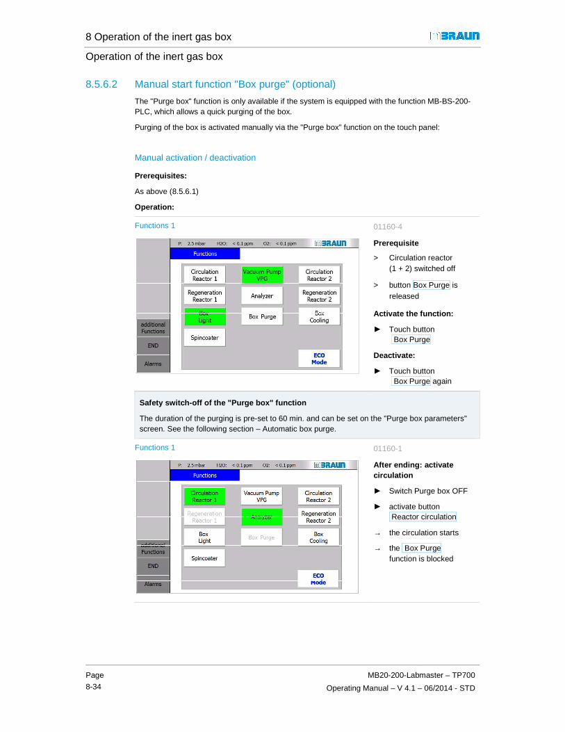
8 Operation of the inert gas box
Operation of the inert gas box
Page
8-34
MB20-200-Labmaster – TP700
Operating Manual – V 4.1 – 06/2014 - STD
8.5.6.2 Manual start function "Box purge" (optional)
The "Purge box" function is only available if the system is equipped with the function MB-BS-200-PLC, which allows a quick purging of the box.
Purging of the box is activated manually via the "Purge box" function on the touch panel:
Manual activation / deactivation
Prerequisites:
As above (8.5.6.1)
Operation:
Functions 1 01160-4
Prerequisite
> Circulation reactor (1 + 2) switched off
> button Box Purge is released
Activate the function:
► Touch button Box Purge
Deactivate:
► Touch button Box Purge again
Safety switch-off of the "Purge box" function
The duration of the purging is pre-set to 60 min. and can be set on the "Purge box parameters" screen. See the following section – Automatic box purge.
Functions 1 01160-1
After ending: activate circulation
► Switch Purge box OFF
► activate button Reactor circulation
→ the circulation starts
→ the Box Purge function is blocked

8 Operation of the inert gas box
MB20-200-Labmaster – TP700
Operating Manual – V 4.1 – 10/2014 - STD
Page
8-35
8.5.6.3 Automatic box purge - (optional)
With the automatic box purge, there is a PLC-controlled purging of the box from an external gas source. The purging of the box is activated at a defined limit value.
As reference values, measurement values for different materials can be parametrised in the PLC - generally the oxygen content is the reference value, other measurement values such as He, N2, H2 or solvents can be set up optionally (see also Chap. 8.4).
This provides a constant quality of the box atmosphere. For example, in case of error during circulation operation, an increase of the O2 concentration in the box is prevented.
Safety
DANGER
Risk of suffocation due to escaping inert gases in case of error (such as open flange, glove tear) if the automatic box purging is permanently activated!
If the operator is away from the system (break times, overnight, weekend):
► Make sure that the parameter for the "Automatic switch-off" function is activated (see automatic box purge parameters, next page)
► If the automatic switch-off is deactivated: ensure a securing of the ambient air in the work room (ensure sufficient ventilation, connected Purge box output to an in-house exhaust air system).
Safety switch-off:
In case of error – such as glove tear, open flange or open pane – there is an O2 increase in the box and with permanently-activated box purging, unlimited operating gas is fed in, which gets into the ambient air.
In order to limit this potential risk of a permanent feed of operating gas into the ambient air, the duration of the automatic box purging can be limited via parameter setting. It is pre-set by MBRAUN to 60 min.
Exception – responsibility of the operator:
Depending on the room size, ventilation or connection of the box purge output to an in-house exhaust air system, the automatic deactivation can be switched off (see below, Parameters section). The operator must ensure that there are no risks to people in the room.
Please heed the safety instruction above and follow the description in Chap. 8.8.1:

8 Operation of the inert gas box
Operation of the inert gas box
Page
8-36
MB20-200-Labmaster – TP700
Operating Manual – V 4.1 – 06/2014 - STD
Automatic box purge parameters
! Heed the information above and the safety instructions.
Box purge parameters 01500-4
1
2
3
On the "Parameter Box Purging" screen, the following can be set:
Limit value
� adjustable value
for the switching on of the automatic box purging function (here: O2)
Activation / deactivation
The automatic "Purge box" function can be switched optionally ON or OFF.
Adjustment range: 1..999 min ; Default: 60 min value 0 min = function deactivated
Automatic switch-off
Risk of suffocation!
If the function is deactivated, the error case is no longer secured!
In case of gross leaks in the box, there can be an unintentional gas feed into the room!
► Heed safety instructions!
► Secure ambient air (ventilation / connection to exhaust air system)!
Switching on again
The purging function can be started again manually right away.
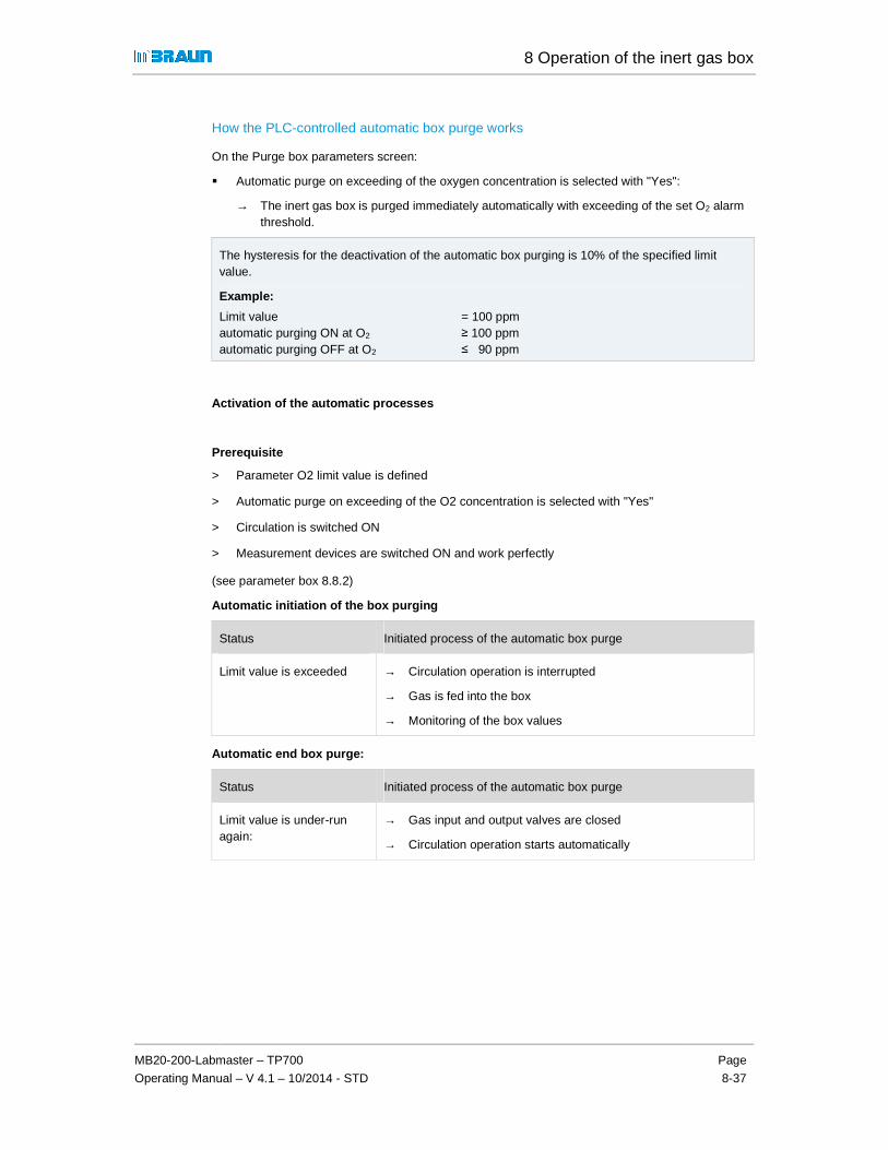
8 Operation of the inert gas box
MB20-200-Labmaster – TP700
Operating Manual – V 4.1 – 10/2014 - STD
Page
8-37
How the PLC-controlled automatic box purge works
On the Purge box parameters screen:
� Automatic purge on exceeding of the oxygen concentration is selected with "Yes":
→ The inert gas box is purged immediately automatically with exceeding of the set O2 alarm threshold.
The hysteresis for the deactivation of the automatic box purging is 10% of the specified limit value.
Example:
Limit value = 100 ppm automatic purging ON at O2 ≥ 100 ppm automatic purging OFF at O2 ≤ 90 ppm
Activation of the automatic processes
Prerequisite
> Parameter O2 limit value is defined
> Automatic purge on exceeding of the O2 concentration is selected with "Yes"
> Circulation is switched ON
> Measurement devices are switched ON and work perfectly
(see parameter box 8.8.2)
Automatic initiation of the box purging
Status Initiated process of the automatic box purge
Limit value is exceeded → Circulation operation is interrupted
→ Gas is fed into the box
→ Monitoring of the box values
Automatic end box purge:
Status Initiated process of the automatic box purge
Limit value is under-run again:
→ Gas input and output valves are closed
→ Circulation operation starts automatically
8 Operation of the inert gas box
Customer's applications in the inert gas box
Page
8-38
MB20-200-Labmaster – TP700
Operating Manual – V 4.1 – 06/2014 - STD
8.6 Customer's applications in the inert gas box
Additional customer equipment, process materials and processes are only permissible in the course of the proper use of the MBRAUN system.
► Please heed the information about the safety concept in Chapter 3, Safety.
It is the customer's responsibility to determine the degree of risk of the applications and if necessary to install and apply additional safety equipment and functions.
► If necessary, a specific standard operating manual must be created for the conditions on-site.

8 Operation of the inert gas box
MB20-200-Labmaster – TP700
Operating Manual – V 4.1 – 10/2014 - STD
Page
8-39
8.7 Additional functions and box equipment (optional)
8.7.1 Additional box equipment (optional)
Designation Function Separate document item Nr.
See Chap.
Box atmosphere:
Particle absorber (various service areas)
Suctioning of particles from processing in the box
misc. 10 A . ff
Differential pressure sensor
Monitoring of the degree of saturation of the particle filter
Supplier documentation
15
UGP Universal measurement device for various gases/solvent vapours
10 A..ff
GSU Determination of a specific gas mixture (H2O/ O2)
10 A..ff
Quick-purge function
For large-volume boxes/multi-box systems: speeding up of the purging of the box
8 A ..ff
Box temperature
Box cooling RKI 80-200-300
Cooling of the box atmosphere 8 C
Cooling/heating of process materials
Refrigerator/externally-mounted cooling container
Cooling of process materials 10 A.. ff
Vacuum dry cabinet VC20
Drying of process materials in a vacuum Supplier documentation
15
Cooling of additional equipment
Circulation cooler Cooling of process heat / additional equipment in the box
Additional equipment for processes in the box
Spincoater MB-SC-200
Coating processes semi-conductors - (turning)
10 A.. ff
Evaporation systems
Evaporation of substances on a carrier 10 A.. ff
Multi-box systems Allow operation with various processes 8 B

8 Operation of the inert gas box
Additional functions and box equipment (optional)
Page
8-40
MB20-200-Labmaster – TP700
Operating Manual – V 4.1 – 06/2014 - STD
8.7.2 Box safety equipment (optional)
Designation Function Document item No.
See Chap.
Over pressure safety valve MB-OSV
Securing of the box pressure; tear securing of the gloves
8 A
Light barrier/curtain Reach-in guard against moving parts in the box
Supplier documentation
8 A ..ff
UV protection pane Protection against UV radiation 8 A.. ff
Box purge from external source
For securing inert gas operation in case of error of the circulation operation
8.5.6

8 A. Analyzer (Optional)
Components: Analyzer – TFT 70
Operating Manual – V 4.1 – 06/2014
Page
8A-1
8 A.1 Oxygen Analyzer MB OX-SE-1 ................................................................. 2 8 A.1.1 Design overview ......................................................................................................... 2 8 A.1.2 Technical Data ........................................................................................................... 3 8 A.1.3 Connection ................................................................................................................. 3
8 A.2 Moisture Analyzer MB MO-SE-1 ............................................................... 4 8 A.2.1 Design overview ......................................................................................................... 4 8 A.2.2 Technical Data ........................................................................................................... 4 8 A.2.3 Connection ................................................................................................................. 5
8 A.3 Calibration of measurements ................................................................... 5

8 A. Analyzer (Optional)
Oxygen Analyzer MB OX-SE-1
Components: Analyzer – TFT 70
Operating Manual – V 4.1 – 06/2014
8 A Analyzer (Optional)
Applies to systems with optional H2O and/or O2 analyzers:
The following analyzers can be used with the system:
Oxygen analyzer MB-OX-SE-1 Moisture analyzer MB MO-SE-1
8 A.1 Oxygen Analyzer MB OX-SE-1
The MB-OX-SE-1 sensor is designed to control the atmosphere of MBRAUN Systems for residual Oxygen content. The measuring range is 0 to 1000 ppm. The measuring range from 0 – 100 ppm is linear.
The semiconductor sensor made of Zirconium dioxide is specific for oxygen, but because of the high sensor temperature and the catalytic activity of the platinum electrodes of the sensor there are low cross-sensitivities for hydrogen as well as possible reactions with aggressive gaseous substances, that can reduce the operational life of the sensor.
! Operating the sensor at oxygen levels of >1000 ppm (e.g. in air) does not damage the sensor element irreversibly, but it should be avoided. If exposed to air, it will take several hours until the sensor will measure low oxygen levels correctly in Inert Gas.
8 A.1.1 Design overview
The MB-OX-SE1 consists of the sensor and a box with integrated electronics and a gas-tight DN40-KF clamp flange. The sensor is protected by a protective cage against mechanical damage. The sensor leads are connected to the electronics by a vacuum-tight feed-through. The electronics are contained in an airtight box mounted directly behind the DN40-KF flange.
The electronic measuring equipment is supplied with 24 VDC. It provides a voltage signal of 0-10 VDC proportional to the oxygen concentration.
Via an additional input, the heater of the sensor element is controlled. If the external input is not used, a jumper has to be set at the electronics.
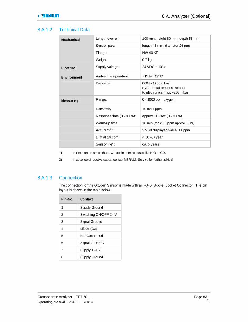
8 A. Analyzer (Optional)
Components: Analyzer – TFT 70
Operating Manual – V 4.1 – 06/2014
Page 8A-3
8 A.1.2 Technical Data
Mechanical Length over all: 190 mm, height 80 mm, depth 58 mm
Sensor-part: length 45 mm, diameter 26 mm
Flange: NW 40 KF
Weight: 0.7 kg
Electrical Supply voltage: 24 VDC ± 10%
Environment Ambient temperature: +15 to +27 °C
Pressure: 800 to 1200 mbar (Differential pressure sensor to electronics max. ≈200 mbar)
Measuring Range: 0 - 1000 ppm oxygen
Sensitivity: 10 mV / ppm
Response time (0 - 90 %): approx.. 10 sec (0 - 90 %)
Warm-up time: 10 min (for < 10 ppm approx. 6 hr)
Accuracy1): 2 % of displayed value ±1 ppm
Drift at 10 ppm: < 10 % / year
Sensor life2): ca. 5 years
1) In clean argon-atmosphere, without interfering gases like H2O or CO2
2) In absence of reactive gases (contact MBRAUN Service for further advice)
8 A.1.3 Connection
The connection for the Oxygen Sensor is made with an RJ45 (8-pole) Socket Connector. The pin layout is shown in the table below.
Pin-No. Contact
1 Supply Ground
2 Switching ON/OFF 24 V
3 Signal Ground
4 Lifebit (O2)
5 Not Connected
6 Signal 0 - +10 V
7 Supply +24 V
8 Supply Ground

8 A. Analyzer (Optional)
Moisture Analyzer (MB MO-SE-1)
Components: Analyzer – TFT 70
Operating Manual – V 4.1 – 06/2014
8 A.2 Moisture Analyzer (MB MO-SE-1)
The MB-MO-SE1 is designed to control the atmosphere of the MBRAUN Systems for residual moisture content. The measuring range is 0 to 500 ppm. The measuring range from 0 – 50 ppm is linear. Above 500 ppm it is possible to make an estimation of the moisture content of the inert gas atmosphere.
The sensor element is made of specifically printed ceramic. The sensor is coated with totally dehydrated phosphoric acid. Water molecules in the gas are absorbed at the phosphoric acid. The electric current of the sensor electrodes separate the water molecules (electrolysis) into H2 and O2.
The flowing current is a directly measurement for water vapor partial pressure of the measuring gas. The primary signal is amplified and temperature compensated indicated.
8 A.2.1 Design overview
The moisture analyzer MB-MO-SE1 consists of the sensor element and a special electronics unit. The sensor is protected by a protective cage against mechanical damage. The sensor leads are connected to the electronics by a vacuum-tight feed-through. The electronics are contained in an airtight box mounted directly to the back of the DN40-KF flange.
Electronics and Sensor Element have been factory-calibrated with certified calibration gases; there are no user-accessible adjustment points.
8 A.2.2 Technical Data
Mechanical Length over all: 205 mm, height 80 mm, depth 58 mm
Sensor-part: length 42 mm, diameter 14 mm
Flange: DN 40 KF
Weight: 0.7 kg
Electrical Supply voltage: 24 VDC ±10%
Environment Ambient temperature: +15 to +27 °C
Pressure: 800 to 1200 mbar (Differential pressure sensor to electronics max. ≈200 mbar)
Measuring Range: 0 - 500 ppm moisture
Sensitivity: 20 mV / ppm
Response time (0 - 90 %): approximately 120 sec. (0 - 90 %)
Warm-up time: 10 min (for < 10 ppm approx. 6 hr)
Accuracy1):
High precision range (0 - 10 ppm): better than 5 % of value
Wide range (10 - 100 ppm): better than 20 % of value
Drift at 10 ppm < 10% / year
Sensor life2): ca. 5 years
1) without interfering gases like NH3
2) with regular maintenance

8 A. Analyzer (Optional)
Components: Analyzer – TFT 70
Operating Manual – V 4.1 – 06/2014
Page 8A-5
8 A.2.3 Connection
The connection for the Moisture Sensor is made with an RJ45 (8-pole) Socket Connector. The pin layout is shown in the table below.
Pin-No. Contact
1 Supply Ground
2 Switching ON/OFF 24 V
3 Signal Ground
4 Not Connected
5 Live bit (H2O)
6 Signal 0 - +10 V
7 Supply +24 V
8 Supply Ground
8 A.3 Calibration of measurements
As default, MBRAUN-measurements are calibrated before delivering.
! It is recommanded to calibrate the measurements yearly by MBRAUN-specialists. Please, contact the service of MBRAUN.
In case of dysfunction, send the measurement unopened and complete to the service of MBRAUN.
On request, analyzers are available as return parts. Ask MBRAUN.
Using Oxygen and moisture analyzer: see chapter Inertgas box.
Cleaning moisture sensors: see chapter 12, Inspection and maintenance

8 A. Analyzer (Optional)
Calibration of measurements
Components: Analyzer – TFT 70
Operating Manual – V 4.1 – 06/2014

9 Operation of the Antechamber
MB20-200-Labmaster – TP700
Operating Manual – V 4.1 - 06/2014 - STD
Page
9-1
9.1 Introduction ............................................................................................9-2 9.1.1 Basic rules .............................................................................................................. 9-2
9.2 Safe antechamber processes ................................................................9-3 9.2.1 Antechamber doors and antechamber atmosphere ............................................... 9-5
9.3 Operating the vacuum pump, antechamber doors and tray ...............9-6 9.3.1 Notes about the vacuum pump .............................................................................. 9-6 9.3.2 Notes for the door operation ................................................................................... 9-7 9.3.3 Operation of mini-antechamber .............................................................................. 9-8 9.3.4 Operating doors on the round antechamber ........................................................... 9-9 9.3.5 Operating locking of the antechamber doors (optional) ........................................ 9-10 9.3.6 Loading antechamber tray .................................................................................... 9-11
9.4 Antechamber processes: manual operation ...................................... 9-12 9.4.1 Loading into the box using the example mini-antechamber ................................. 9-12 9.4.2 Unloading material from the box .......................................................................... 9-14
9.5 Antechamber processes: PLC-controlled .......................................... 9-16 9.5.1 Overview of antechamber screens ....................................................................... 9-16 9.5.2 Description of antechamber screens .................................................................... 9-17 9.5.3 Transfer in ............................................................................................................ 9-21 9.5.4 Transfer out .......................................................................................................... 9-25
9.6 Additional equipment and functions (optional) ................................. 9-26 9.6.1 Additional functions .............................................................................................. 9-26 9.6.2 Additional equipment ............................................................................................ 9-26

9 Operation of the Antechamber
Introduction
Page
9-2
MB20-200-Labmaster – TP700
Operating Manual – V 4.1 - 06/2014- STD
9 Operation of the Antechamber
The structure and functions of the antechamber are described in Chapter 2 System components. See Chap. 2.4.
9.1 Introduction
This operating manual describes the safe handling of antechamber processes.
� Chapter 9.3 shows the mechanical operation aspects of vacuum pump, door locking and antechamber tray.
� The manual operation of an antechamber process is depicted in exemplary fashion in Chap. 9.4 using the mini-antechamber (150 mm) for the understanding of the principle of an antechamber process.
� Chap. 9.5 shows the operation of PLC-controlled antechamber processes using the touch panel.
� Chap. 9.6 provides an overview of optional additional equipment and functions.
9.1.1 Basic rules
The quality and degree of safety of the antechamber processes depend on adherence to the operating steps described in this operating manual and the type of process materials used.
Basic rules for performing antechamber processes
► Always ensure good ventilation of the room
► Never open the inner and outer antechamber doors at the same time
Before opening the inner antechamber door:
► Equalize the antechamber atmosphere to the inert box atmosphere: Always perform the required evacuation and refilling cycles and follow the action instructions for performing antechamber processes.
! Always follow the specific safety instructions in Chap. 9.2.

9 Operation of the Antechamber
MB20-200-Labmaster – TP700
Operating Manual – V 4.1 - 06/2014 - STD
Page
9-3
9.2 Safe antechamber processes
Standard systems for product protection
Standard antechamber processes are designed for product protection for normal operating conditions with use of process materials in category 0 or 1 (see Chapter 3 Safety concept and proper use).
Use of hazardous process materials (category IV and EX)
If processes/process materials with specific risks are used,
� that are sensitive, toxic or very flammable
� or emit in some other way (such as radioactivity)
In these cases, additional safety equipment and/or functions for antechamber processes are required.
► Follow the instructions in the basic safety chapter for the classification and evaluation of substances (Chapter 3).
► If necessary, ensure the use of the required additional equipment!
► In case of questions, please contact MBRAUN SERVICE.
Antechamber processes
CAUTION
Incorrect operation of the antechamber processes can compromise the health of the operator. The oxygen of the ambient air can damage process material.
► Always follow the instructions in this operating manual
► If necessary, use additional safety equipment and functions and personal protective equipment (PPE)
► If necessary, follow your operation-specific standard flow plan

9 Operation of the Antechamber
Safe antechamber processes
Page
9-4
MB20-200-Labmaster – TP700
Operating Manual – V 4.1 - 06/2014- STD
Transport containers
WARNING
Risk of explosion or implosion from transport containers that are not vacuum-suitable. Depending on the process materials used, there can be additional risks for people.
► With transport containers with gas-like or liquid content (e.g. bottles and containers): note that they must stand up to the pressure changes during evacuation/refilling of the antechamber
► Do not evacuate liquids below their vapour pressure at the given temperature.
► If necessary, use vacuum-suitable transport containers.
NOTICE
Ambient air trapped in transport containers causes contamination of the box atmosphere.
There can be damage to process materials, which depending on the type of materials can cause unexpected risks.
► Open closed containers (boxes, bottles, etc.) – insofar as possible – before loading
► Always provide transport containers with required stickers and warning labels.

9 Operation of the Antechamber
MB20-200-Labmaster – TP700
Operating Manual – V 4.1 - 06/2014 - STD
Page
9-5
9.2.1 Antechamber doors and antechamber atmosphere
9.2.1.1 Loading
NOTICE
Oxygen and moisture in the ambient air contaminate the box atmosphere and can trigger unexpected reactions and do damage to process materials. Measurement instruments can be damaged.
► Adhere to on-site conditions
► Never open the inner and outer antechamber doors at the same time
► Never open the inner antechamber door if the antechamber is filled with ambient air.
Before opening the antechamber inner door:
► Always match the antechamber atmosphere to the highly-pure atmosphere in the box through several cycles of evacuation/refilling of the antechamber with working gas.
9.2.1.2 Unloading
Unloading cycle in standard systems:
After closing the inner antechamber door, the outer antechamber door can be opened. The inert box atmosphere that has penetrated the mini- and round antechambers may escape into the room (see section 9.4.2).
Please note: Only allowed with the use of non-toxic gases and process materials! (See Chap. 3 Safety).
9.2.1.3 After completing an antechamber process
WARNING
Health hazard and/or risk to process materials in case of open antechamber doors.
After completing an antechamber process:
► Always make sure that the outer and inner door of the antechamber are closed.

9 Operation of the Antechamber
Operating the vacuum pump, antechamber doors and tray
Page
9-6
MB20-200-Labmaster – TP700
Operating Manual – V 4.1 - 06/2014- STD
9.3 Operating the vacuum pump, antechamber doors and tray
Before the operation of the antechamber processes is described, this section provides an overview of prerequisites for operation of the vacuum antechamber, the antechamber doors and the antechamber tray.
9.3.1 Notes about the vacuum pump
Exhaust / exhaust air
MBRAUN recommends connecting the exhaust system of the vacuum pump to an in-house exhaust system.
Switching on/off
Before starting the antechamber processes
- Switch on the vacuum pump
System with a single vacuum pump (VPG)
The vacuum pump is primarily used for box pressure regulation, its second priority is for evacuation processes of the antechamber (cf. Section 9.5 PLC-controlled antechamber processes).
In case of very frequent antechamber processes, MBRAUN recommends using a separate vacuum pump for antechamber processes.
System with a separate vacuum pump for antechamber processes (VP)
If the vacuum pump is no longer needed:
► Switch off vacuum pump on the touch panel� The pump is switched on again automatically for the next evacuation/refill cycle.
2-antechamber system and VP
If two antechambers use a single vacuum pump:
Only one of the antechambers at a time can run through an automatic cycle or be evacuated manually. The first activated antechamber takes priority.
ECO-Mode (optional)
in ECO-Mode the vacuum pump is switched down at a defined point in time. See special chapter 6 A (optional).

9 Operation of the Antechamber
MB20-200-Labmaster – TP700
Operating Manual – V 4.1 - 06/2014 - STD
Page
9-7
9.3.2 Notes for the door operation
Damage to the antechamber door in case of incorrect operation
An evacuated antechamber under vacuum cannot be opened. With an attempt to open an evacuated antechamber, the door locking mechanism can be damaged.
Door seals
Dirt. solvents and foreign bodies can damage the door seals and door mechanism.
Make sure that the door and the door seals are free of dirt and objects before you close the antechamber door.
Check the seals regularly to make sure they are tight
Risk of crushing in case of improper operation
Keep your hands away from the antechamber door area.

9 Operation of the Antechamber
Operating the vacuum pump, antechamber doors and tray
Page
9-8
MB20-200-Labmaster – TP700
Operating Manual – V 4.1 - 06/2014- STD
9.3.3 Operation of mini-antechamber
9.3.3.1 Operating doors of the mini-antechamber
The mini-antechamber is equipped with a manually-activated lever locking mechanism.
Closed outer door:
> Lever is locked in the bracket
Opening the outer door:
To open:
► Lift lever and pull out of the bracket
► Unfold cover
To close:
► Place the lever in the bracket and lock
Closed inner door
> Lever is locked in the bracket
Opening the inner door
► Open and close as above.
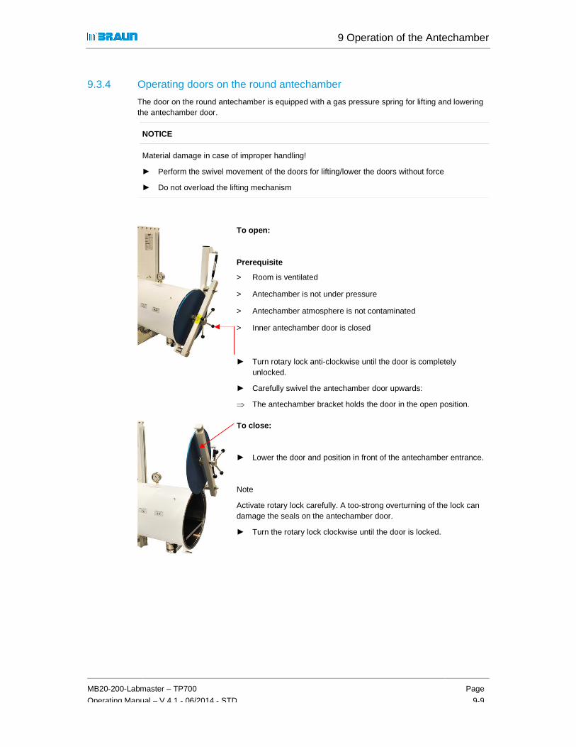
9 Operation of the Antechamber
MB20-200-Labmaster – TP700
Operating Manual – V 4.1 - 06/2014 - STD
Page
9-9
9.3.4 Operating doors on the round antechamber
The door on the round antechamber is equipped with a gas pressure spring for lifting and lowering the antechamber door.
NOTICE
Material damage in case of improper handling!
► Perform the swivel movement of the doors for lifting/lower the doors without force
► Do not overload the lifting mechanism
To open:
Prerequisite
> Room is ventilated
> Antechamber is not under pressure
> Antechamber atmosphere is not contaminated
> Inner antechamber door is closed
► Turn rotary lock anti-clockwise until the door is completely unlocked.
► Carefully swivel the antechamber door upwards:
⇒ The antechamber bracket holds the door in the open position.
To close:
► Lower the door and position in front of the antechamber entrance.
Note
Activate rotary lock carefully. A too-strong overturning of the lock can damage the seals on the antechamber door.
► Turn the rotary lock clockwise until the door is locked.

9 Operation of the Antechamber
Operating the vacuum pump, antechamber doors and tray
Page
9-10
MB20-200-Labmaster – TP700
Operating Manual – V 4.1 - 06/2014- STD
9.3.5 Operating locking of the antechamber doors (optional)
The antechamber can be equipped with an antechamber lock in order to prevent the simultaneous opening of the inner and outer doors.
! Before opening the antechamber door:
Make sure that the lock is released before you try to open an antechamber door.
Locked antechamber door
Display on panel screen
Red dot = door locked
Released antechamber door
Display on panel screen
Locking: outer ring attached star handle is blocked
Locking: outer ring lifted up star handle free to turn

MB20-200-Labmaster – TP700
Operating Manual – V 4.1 - 06/2014 - STD
9.3.6 Loading antechamber tray
Prerequisites
Loading: >
Unloading: >
Material preparation
► Make sure that the packaging/containers are vacuum
► If necessary, place material in vacuum
► Open closed containers (boxes, bottles, etc.)
Loading
If no tray is available:
If a tray is available: procedure as before and:
9 Operation of the Antechamber
STD
antechamber tray
Inner door is closed ► Open outer door
Outer door is closed ► Open inner door
Make sure that the packaging/containers are vacuum-suitable
If necessary, place material in vacuum-suitable containers that can be sealed
Open closed containers (boxes, bottles, etc.) – insofar as possible – before loading
► Bring the material directly into the antechamber
► Make sure that no foreign bodies prevent the closing of the antechamber door
Loading:
► Close the outer door of the antechamber.
Unloading:
► Close the inner door of the antechamber.
► Start the antechamber process (see below)
If a tray is available: procedure as before and:
► remove tray, place material on it, tray plus material into the antechamber.
Optional for pneumatic doors:
Sensor below the tray is activated if the tray is pushed into the starting position mechanism is released
Regard the activation light.
Operation of the Antechamber
Page
9-11
Open outer door
Open inner door
before loading
Bring the material directly into the
Make sure that no foreign bodies prevent the antechamber door
Close the outer door of the antechamber.
Close the inner door of the antechamber.
Start the antechamber process (see below)
remove tray, place material on it, then push tray plus material into the antechamber.
Sensor below the tray is activated if the tray is pushed into the starting position � Door

9 Operation of the Antechamber
Antechamber processes: manual operation
Page
9-12
MB20-200-Labmaster – TP700
Operating Manual – V 4.1 - 06/2014- STD
9.4 Antechamber processes: manual operation
9.4.1 Loading into the box using the example mini-antechamber
Ste
p
Sta
tus
of
door
s
Status of atmosphere of box / antechamber (AC)
Sta
tus
ante
cham
ber
pres
sure
Sta
tus
man
ual v
alve
► Action Fig Mini-antechamber
1 Inside CLOSED
Outside OPEN
Atm
CLOSED
- Unlock cover
- Open cover.
2 Inside CLOSED
Outside OPEN
Atm
CLOSED
- Pull out tray
- Place material on tray +
- insert into the antechamber
3 Inside CLOSED
Outside OPEN
Atm
CLOSED
Locking the outer door:
- Close cover.
- Lock cover.
4 Inside CLOSEDOutside CLOSED
Vacuum-0.9 to -1.0 bar
EVAK
Evacuation
5 Inside CLOSEDOutside CLOSED
> Atm
≤-0.4 bar.
Refilling
Refilling from the boxoptional:from external gas source

9 Operation of the Antechamber
MB20-200-Labmaster – TP700
Operating Manual – V 4.1 - 06/2014 - STD
Page
9-13
Ste
p
Sta
tus
of
door
s
Status of atmosphere of box / antechamber (AC)
Sta
tus
ante
cham
ber
pres
sure
Sta
tus
man
ual v
alve
► Action Fig Mini-antechamber
6 Inside CLOSEDOutside CLOSED
Change vacuum/atm. flipEnd: = box pressure
Evacuate / refill
Repeat several times until antechamber is inert - 150 Mini-antechamber: 2x - 390 Main antechamber: 3x
7 Inside CLOSEDOutside CLOSED
= Box pressure
CLOSED
Close valve
8 Inside OPEN
Outside CLOSED
= Box pressure
CLOSED
- Unlock inner door
- Open inner door
- Insert material from the antechamber into the box
- Close inner door
9 Inside CLOSEDOutside CLOSED
= Box pressure
CLOSED
./.
The material is loaded

9 Operation of the Antechamber
Antechamber processes: manual operation
Page
9-14
MB20-200-Labmaster – TP700
Operating Manual – V 4.1 - 06/2014- STD
9.4.2 Unloading material from the box
! If the outer antechamber door was open, the inner walls may be moist. To prevent this, MBRAUN recommends performing an evacuation and refilling procedure after opening the outer antechamber door.
Ste
p
Sta
tus
of
door
s
Status of atmosphere
Sta
tus
ante
cham
ber
pres
sure
Sta
tus
man
ual v
alve
► Action Example of mini-antechamber
1 Inner door CLOSED Outer door CLOSED
check whether
= Box pressure
CLOSED
Check: is the antechamber inert? – No � step 2 Yes� step 3
(2) Inner door CLOSED Outer door CLOSED
optional if antechamber atmosphere is not inert
Vacuum / Box pressure final: = Box pressure
Evacuate / refill
Repeat several times until the antechamber atmosphere matches the box atmosphere (it is inert)
- 150 Mini-antechamber: 2x - 390 Main antechamber: 3x
3 Outer door CLOSED Inner door CLOSED
= Box pressure
CLOSED
- / - The antechamber is inert:
- Open inner door
4 Outer door CLOSED Inner door OPEN
= Box pressure
CLOSED
- Place material in the antechamber
- Close inner door
5 Inner door CLOSED Outer door CLOSED
= Box pressure
CLOSED
Optional:
Perform step (6) –
Standard: continue with step 7

9 Operation of the Antechamber
MB20-200-Labmaster – TP700
Operating Manual – V 4.1 - 06/2014 - STD
Page
9-15
Ste
p
Sta
tus
of
door
s
Status of atmosphere
Sta
tus
ante
cham
ber
pres
sure
Sta
tus
man
ual v
alve
► Action Example of mini-antechamber
(6) Inner door CLOSED Outer door CLOSED
Optional: Refill with ambient air
= Box pressure
CLOSED
if necessary, evacuate/refill with
ambient air /
End: = atmosphere pressure
7 Inner door CLOSED Outer door CLOSED
Standard
= Atm.pressure
- Open outer door
8 Inner door CLOSED Outer door OPEN
= Atm.pressure
CLOSED
- Remove material from the antechamber
- Close outer antechamber door

9 Operation of the Antechamber
Antechamber processes: PLC-controlled
Page
9-16
MB20-200-Labmaster – TP700
Operating Manual – V 4.1 - 06/2014- STD
9.5 Antechamber processes: PLC-controlled
9.5.1 Overview of antechamber screens
Antechamber 1 screen 01601-1
Example: antechamber in manual operation
(1) Manual operation with functions
(2) Evacuation
(3) Refilling
Antechamber 1 screen 01601-2
Optional automatic operation:
(1) Automatic
(2) Function Antechamber Cycle
(3) Second Antechamber: call up with navigation button Antech. 2
Antechamber 1 Parameters screen 01600-1
After touching the button
Parameter
Parameter adjustments for automatic operation
Antechamber 1 Trend Curve screen 01602
Navigation: Antechamber 1 screen:
Call up trend curve
► Touch navigation button Trend Curve

9 Operation of the Antechamber
MB20-200-Labmaster – TP700
Operating Manual – V 4.1 - 06/2014 - STD
Page
9-17
9.5.2 Description of antechamber screens
9.5.2.1 Antechamber screen
The antechamber screen indicates the status of the antechamber processes.
The antechamber processes are activated and deactivated with the function keys
Antechamber 1 screen 01601-2
Example: automatic operation (optional)
(1) Status line
(2) Navigation buttons
(3) Display pictogram
(4) Function button field
Only in the automatic antechamber process:
Display of the steps in the automatic antechamber process
(1) Status line
Key calls up the "Antechamber 2" screen (for systems with 2 antechambers)
(2) Navigation
Button calls up the "Trend Curve" screen (see 9.5.2.3)
Button calls up the "Parameters" screen (see 9.5.2.2)
back to the "Start screen"
The pressure of the automatic antechamber is measured with pressure sensors.
The current value is displayed in the light blue field:
The antechamber pressure is displayed graphically as a blue bar: the lower the pressure in the antechamber, the lower the bar height.
(3) Pictograms:pressure indicator
Note:
If the system is equipped with just one manometer, no values appear on the touch panel

9 Operation of the Antechamber
Antechamber processes: PLC-controlled
Page
9-18
MB20-200-Labmaster – TP700
Operating Manual – V 4.1 - 06/2014- STD
Cont. (3)
Status indicator
- Valves (input/output)
- Vacuum pump
The antechamber processes are activated/deactivated with the function buttons.
(4) Function button/antechamber status indicator field
In manual operation:
evacuation of the antechamber function
In manual operation:
refilling of the antechamber function
In automatic operation:
Antechamber cycle function: Automatic flow of the evacuate/refill cycle
Change between the modes:
Manual operation and automatic operation
In manual operation: release of the evacuate – refill buttons In automatic operation: release of the "Antechamber cycle" button
Vacuum pump
Here: vacuum pump gas purifier
Optional: additional pump VP

9 Operation of the Antechamber
MB20-200-Labmaster – TP700
Operating Manual – V 4.1 - 06/2014 - STD
Page
9-19
9.5.2.2 Antechamber parameters
Antechamber 1 Parameters 01600-1
Automatic antechamber parameters
Optional: display of parameters locking of inner door
The parameters are pre-set by MBRAUN and can be adapted if necessary.
Parameters for the antechamber cycle evacuate + refill
Description MBRAUN setting
Unit Customer setting
min max min max
Threshold value intermediate refill
Value for the pressure up to which the antechamber is filled between two evacuation steps.
400 mbar 1x10⁻² 50
Threshold value vacuum leak test
Target value for the vacuum leak test.
5x10⁻¹ mbar 1x10⁻² 10
Threshold value final vacuum
Target value for the pressure at which the evacuation ends.
5x10⁻¹ mbar 1x10⁻² 10
Number of pump refill cycles
Number of pump evacuation/refill cycles
1 X 1 10
Maximum evacuation time [min]
Period in which the value for "Threshold value vacuum leak test" must be reached. In case of error, the cycle is stopped and the message "Time exceeded" appears.
5 1 10

9 Operation of the Antechamber
Antechamber processes: PLC-controlled
Page
9-20
MB20-200-Labmaster – TP700
Operating Manual – V 4.1 - 06/2014- STD
Description MBRAUN setting
Unit Customer setting
min max min max
Maximum leakage rate [steps]
Value for the maximum permissible pressure increase during the two steps of the vacuum leak tightness test in a defined time period.
Example:2x10⁻¹ mbar to 4x10⁻¹ mbar If the parameter value is reached, the process is stopped and the message "Antechamber leaks" is displayed.
3 1 10
Lock inner door after [h]
Optional for cover locking: if the antechamber is not used for a longer time, the inner door can be locked after an adjustable time in order to secure the purity of the box atmosphere.
Default: 60
Value 0 = function deactivated
H 1.. 999
9.5.2.3 Trend displays for the antechamber
The trend display represents the pressure of the antechamber over the course of time.
Antechamber 1 Trend Curves 01602
Optional: Trend curve temperature; activated via "Temperature" navigation button

9 Operation of the Antechamber
MB20-200-Labmaster – TP700
Operating Manual – V 4.1 - 06/2014 - STD
Page
9-21
9.5.3 Transfer in
9.5.3.1 Preparations
The antechamber atmosphere is prepared for the loading and unloading of materials through evacuation and refilling with inert gas and ambient air. Parameters are pre-set for the PLC-controlled processes (see above). The processes are activated on the touch panel
9.5.3.2 Manual operation: evacuation and refilling
The antechamber functions "evacuation" and "refilling" are started and stopped manually with a button on the touch panel.
The antechamber pressure is displayed on the manometer on the antechamber. During the evacuation and refilling process:
► Observe antechamber pressure
End pressure refilling: 200-400 mbar End pressure evacuation: < 1 mbar End pressure: Box pressure
Prerequisite
Antechamber doors > Both antechamber doors are closed
The vacuum pump is switched on automatically at the evacuation start.
With an additional vacuum pump:
If necessary switch on: on Functions 2 or Antechamber 1 screen
► Touch button Vacuum pump VPG
Activate "manual operation" operating mode
► Touch button Manual
→ The colour of the button changes from GREY to GREEN
→ The Evacuate and Refill buttons are released

9 Operation of the Antechamber
Antechamber processes: PLC-controlled
Page
9-22
MB20-200-Labmaster – TP700
Operating Manual – V 4.1 - 06/2014- STD
Antechamber 1 - manual operation screen 01601-1
Status:
Manual operation switched on:
→ The "Evacuate" and "Refill" buttons are released
→ The automatic mode is locked
Evacuation and refilling cycle:
To evacuate:
► Touch button Evacuate
► Evacuate until antechamber pressure < 1 mbar
To refill:
► Touch button Refill
► Intermediate refilling up to antechamber pressure 200 .. 400 mbar
Repeat 3 x: Evacuate cycle -- execute refilling 3 x
Then: ► Refill up to box pressure
► Close refill valve: touch button Refill again
Door operation after evacuation -- refilling
After completing the evacuation and refill process and reaching the target pressure, one door apiece (inside or outside) can be opened.
When loading: > Reaching of the box pressure:
► Open inner door
When unloading > Atmosphere pressure: ► Open outer door
Please note:
The refilling of the antechamber in manual operation is limited to 10 minutes; after that, the function switches off automatically.
→ the "Refill" function can be switched on again
→ the "Automatic operation" function can be switched on
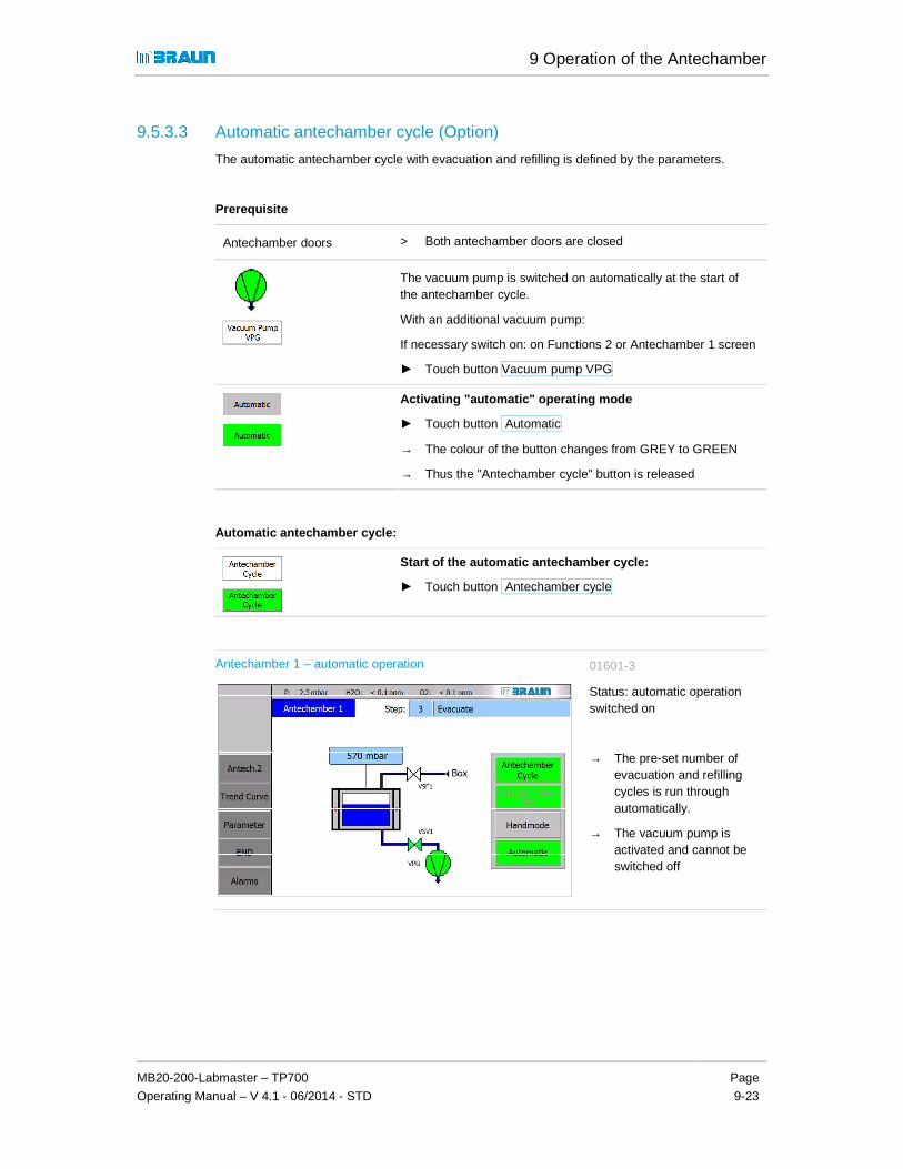
9 Operation of the Antechamber
MB20-200-Labmaster – TP700
Operating Manual – V 4.1 - 06/2014 - STD
Page
9-23
9.5.3.3 Automatic antechamber cycle (Option)
The automatic antechamber cycle with evacuation and refilling is defined by the parameters.
Prerequisite
Antechamber doors > Both antechamber doors are closed
The vacuum pump is switched on automatically at the start of the antechamber cycle.
With an additional vacuum pump:
If necessary switch on: on Functions 2 or Antechamber 1 screen
► Touch button Vacuum pump VPG
Activating "automatic" operating mode
► Touch button Automatic
→ The colour of the button changes from GREY to GREEN
→ Thus the "Antechamber cycle" button is released
Automatic antechamber cycle:
Start of the automatic antechamber cycle:
► Touch button Antechamber cycle
Antechamber 1 – automatic operation 01601-3
Status: automatic operation switched on
→ The pre-set number of evacuation and refilling cycles is run through automatically.
→ The vacuum pump is activated and cannot be switched off

9 Operation of the Antechamber
Antechamber processes: PLC-controlled
Page
9-24
MB20-200-Labmaster – TP700
Operating Manual – V 4.1 - 06/2014- STD
Operation of the antechamber doors (standard)
Standard systems:
After completing an antechamber cycle, both antechamber doors are released.
Equipment with automatic door locking (optional):
After run-through of a complete antechamber cycle:
→ both antechamber doors are released –
→ however only one of the two doors can be opened:
After opening the outside doors
→ the inside door is locked
→ only after another run-through of a complete antechamber cycle:
→ release of the inside door
After closing the inside door
→ both doors are released for opening
(see also section 9.6.1 Automatic cover locking).
! Inner door locking
If the antechamber is not used for a longer time, a pure antechamber atmosphere is no longer guaranteed. Therefore, the inner door can be locked after a particular time (see Chap. 9.5.2.2: Parameters for inner door locking).
Before release of the door, the pre-set number of antechamber cycles is run through.
! Pressure disturbances
In case of box pressure disturbances or disturbances of the antechamber pressure, please observe Chapter 11 Troubleshooting.

9 Operation of the Antechamber
MB20-200-Labmaster – TP700
Operating Manual – V 4.1 - 06/2014 - STD
Page
9-25
9.5.4 Transfer out
Flow unloading of material
1 Antechamber doors > Both antechamber doors are closed
2 Antechamber atmosphere
> The antechamber is filled with inert gas
> Antechamber pressure and box pressure are the same
3 Inner antechamber door > The antechamber door is released / can be opened
4 Loading antechambers ► Load the antechamber from the box with material
5 Inner antechamber door ► Close the inner antechamber door
6 Antechamber atmosphere
In case of contaminated box atmosphere:
► Evacuate antechamber / refill (manual operation or automatic - see above)
optional: refill with ambient air
→ End pressure: atmosphere
7 Outer antechamber door → The antechamber door is released / can be opened
8 Antechamber loading ► Remove material from the antechamber from the outside
► If necessary, reload
9 Outer antechamber door ► Close
9 Operation of the Antechamber
Additional equipment and functions (optional)
Page
9-26
MB20-200-Labmaster – TP700
Operating Manual – V 4.1 - 06/2014- STD
9.6 Additional equipment and functions (optional)
9.6.1 Additional functions
Equipment Function see Chap.
Refill the antechamber with inert gas from external source*)
Note:
*) This always requires an additional safety pressure control valve on the antechamber!
� To speed up antechamber processes: for large antechambers, whose inner volume is not a lot smaller than that of an inert gas box.
� If the antechamber should not be flooded with contaminated box atmosphere (e.g. in case of the use of solvents or special gases in the box). This always requires
9 A ff
Purging of the antechamber in over pressure (= purge antechamber)
Inertising of the antechamber for use of vacuum-sensitive materials
9 A ff
Refilling of the antechamber with ambient air (unloading)
For large antechambers; with the use of gases and/or process materials that are hazardous to health/the environment
9 A ff
9.6.2 Additional equipment
Equipment Function see Chap.
Door locking Prevents the simultaneous opening of inside and outside doors of the antechamber
9.5.3.3
2-antechamber operation Allows directed production flows in the box / if necessary, different conditions (e.g. vacuum antechamber and purge antechamber)
9.5.1 / 9.5.2
T-antechamber Transfers of process materials in multi-box operation (box to box; box-outside)
9 A ff
Button operation Antechambers can (also) be equipped with external button operation (e.g. T-antechamber or 2-antechamber operation)
9 A ff
Antechamber oven Heating up of process materials under vacuum
10 A ff

10 Additional equipment (optional)
MB20-200-Labmaster – TP700
Operating Manual – V 4.1 – 06/2014 - STD
Page
10-1
10.1 Safety ............................................ ........................................................ 10-2
10.2 MBRAUN additional equipment ....................... ................................... 10-3 10.2.1 Additional equipment box ..................................................................................... 10-3 10.2.2 Additional equipment antechamber ...................................................................... 10-6
10.3 Customer-specific components ...................... .................................... 10-7
10.4 Other manufacturers' components ................... .................................. 10-7

10 Additional equipment (optional)
Safety
Page
10-2
MB20-200-Labmaster – TP700
Operating Manual – V 4.1– 06/2014 - STD
10 Additional equipment (optional)
Additional equipment can be integrated into a MBRAUN standard system:
� MBRAUN additional components
� Other manufacturers' additional components
� Customer-specific components
These can be used to create solutions for customer-specific processes.
10.1 Safety
Proper Use / Misuse
Proper use / misuse are described in the specific additional chapters. Please follow the instructions there.
Emergency OFF
If components are integrated into the MBRAUN system and equipped with an EMERGENCY OFF switch, please follow the note below:
DANGER
Personal injury and environmental damage due to incorrect operation!
EMERGENCY OFF buttons which are on third-party components only switch off the respective component!
► In case of danger, switch off the main switch on the system's control cabinet!

10 Additional equipment (optional)
MB20-200-Labmaster – TP700
Operating Manual – V 4.1 – 06/2014 - STD
Page
10-3
10.2 MBRAUN additional equipment
10.2.1 Additional equipment box
Designation Function Separate document item Nr.
See
Box atmosphere:
Particle absorber (various service areas)
Suctioning of particles from processing in the box
misc. Chap. 10
Differential pressure sensor
Monitoring of the degree of saturation of the particle filter
Equipment of third-party suppliers-
Chap. 14
UGP
Universal measurement device for various gases/solvent vapours
Contact MBRAUN Service
Chap. 10
GSU
Determination of a specific gas mixture (H2O/ O2)
1600664 Chap. 10
Oxygen sensors
Monitoring of oxygen content in the box atmosphere (ppm and % range)
Contact MBRAUN Service
Annex and Chap. 13
Moisture sensor
Monitoring of the moisture content in the box and antechamber atmosphere
1600685 Annex and Chap. 13
Use of solvents

10 Additional equipment (optional)
MBRAUN additional equipment
Page
10-4
MB20-200-Labmaster – TP700
Operating Manual – V 4.1– 06/2014 - STD
Designation Function Separate document item Nr.
See
Regulating LMF externally
Removing solvents
Regulate LMF normally / internally for gas purification or
Regulate LMF with hand valves externally for gas purification for retrofitting in the frame of the box
Chap. 10 A ff
Multi-box systems Allows operation with different processes with different quality of the box atmosphere
Chap. 10
Box temperature
Box cooling RKI 80-200-300
Cooling of the box atmosphere 1600328 Chap. 10 A ff and Chap. 15
Handling process materials
Refrigerator
Cooling of process materials Chap. 10 A ff.
Cold Well
Cooling of process materials Chap. 10 A ff.

10 Additional equipment (optional)
MB20-200-Labmaster – TP700
Operating Manual – V 4.1 – 06/2014 - STD
Page
10-5
Designation Function Separate document item Nr.
See
Vacuum-drying cabinet VC20
Drying of process materials in a vacuum Equipment of third-party suppliers-
Chap. 15
Cooling of additional equipment
Circulation cooler
Cooling of process heat / additional equipment in the box
2801554
Shelves in the box
Storage areas for process materials
Additional equipment for processes in the box
Spincoater MB-SC-200
Coating processes semi-conductor - (spinning)
1604510 other see Chap. 10
Box protective equipment
Over pressure safety valve MB-OSV
Securing of the box pressure; tear securing of the gloves
Light curtain Reach-in guard against moving parts in the box
Third party equipment
UV protection pane Protection against UV radiation

10 Additional equipment (optional)
MBRAUN additional equipment
Page
10-6
MB20-200-Labmaster – TP700
Operating Manual – V 4.1– 06/2014 - STD
10.2.2 Additional equipment antechamber
Designation Function Separate document item Nr.
See
Antechamber types
T-antechamber
In multi-box systems: Transfer processes between 2 boxes or between box and outside environment
Chap. 9 A ff.
Oven antechamber 250°C stand-alone
Heating up of process materials under vacuum
Chap. 9 A ff.
Heatable mini-antechamber
Heating up of process materials under vacuum
Chap. 10 A ff.
Oven antechamber VOH-600
Heating up of process materials under vacuum up to 600°C
Chap. 10 A ff
Functions
Purge antechamber Transfers of vacuum-sensitive materials; Purging of the antechamber with inert gas / ambient air in over pressure
Chap. 9 A ff.

10 Additional equipment (optional)
MB20-200-Labmaster – TP700
Operating Manual – V 4.1 – 06/2014 - STD
Page
10-7
10.3 Customer-specific components
MBRAUN can integrated customer-specific components in inert gas systems. This way, customer-specific processes, special controller functions and safety requirements can be set up.
Special requirements and customer requests can be planned and implemented in consultation with the MBRAUN Service Department.
! For the integration of customer-specific components /process systems into a standard inert gas system:
The responsibility for the safe handling of customer-specific processes lies with the customer, including the documentation and training of personnel.
10.4 Other manufacturers' components
MBRAUN inert gas systems can be equipped with components from third-party manufacturers, for example:
� Vacuum pump(s)
� Compressor(s) for system cooling
� Compressor(s) for freezers
The original supplier documentation is a component of the scope of delivery.See Chap. 14 Supplier documentation
MBRAUN assumes no liability for the content of the documentation of third-party manufacturers.

10 Additional equipment (optional)
Other manufacturers' components
Page
10-8
MB20-200-Labmaster – TP700
Operating Manual – V 4.1– 06/2014 - STD

11 Trouble shooting
MB20-200-Labmaster – TP700
Operating Manual – V 4.1 – 06/2014 - STD
Page
11-1
11.1 Eliminating faults (general/mechanical) ............................................. 11-2 11.1.1 PLC ............................................................................ Error! Bookmark not defined. 11.1.2 Gas purifier ........................................................................................................... 11-2 11.1.3 Box ....................................................................................................................... 11-2 11.1.4 Antechambers ...................................................................................................... 11-4
11.2 Opto-acoustic alarm (optional) ........................................................... 11-5
11.3 Acknowledge/delete warning messages (PLC) .................................. 11-6
11.4 Definition of the alarm and warning messages (PLC) ....................... 11-7
11.5 Recommissioning after cancellation and power failure .................. 11-17 11.5.1 Normal flow regeneration ................................................................................... 11-17 11.5.2 Regeneration of the gas purifier RKM ................................................................ 11-17 11.5.3 Regeneration of the gas purifier LMF ................................................................. 11-18
11.6 Error search: leak test ....................................................................... 11-18

11 Trouble shooting
Eliminating faults (general/mechanical)
Page
11-2
MB20-200-Labmaster – TP700
Operating Manual – V 4.1 – 06/2014 - STD
11 Trouble shooting
11.1 Eliminating faults (general/mechanical)
11.1.1 PLC
Fault Remedy See Chap.
Start screen does not appear after switching on:
► Check communication Panel + PLC- established?
► Check connector and electrical supply
Fault not eliminated:
► Contact MBRAUN Service
11.1.2 Gas purifier
Fault Remedy See Chap.
See Error messages 11.4 See Error messages 11.4 Chap. 12
11.1.3 Box
Fault Remedy See Chap.
O2 and H2O values increase ► Regeneration of the reactors necessary or switch over to the second reactor (if available)
► Perform leak test
7.3.2
The O2 measurement value sinks very slowly to values below 10 ppm, although a greater purity of the box atmosphere must be assumed
Before an error in the measurement device is assumed:
► Check systems for disturbing influences: e.g. influences due to hydrogen or other gas components in the inert gas atmosphere, which cause increased indications.
► In case of a fault, send the device unopened and complete to MBRAUN Service.
see 12.5.1.2
See separate documentation MB-OX-SE1

11 Trouble shooting
MB20-200-Labmaster – TP700
Operating Manual – V 4.1 – 06/2014 - STD
Page
11-3
Fault Remedy See Chap.
Imprecise measurement values of the sensors
Note the duration until sensors work correctly:
- O2 sensors: after exposure to air several house -H2O sensors up to 24 hours.
See appendix, documentation MB-OX-SE1 + MB-MO-SE1
Pressure drop / pressure increase
O2 / H2O increase
Temperature increase / drop
Glove tear *) Securing with gloveport covers; eliminate cause;
Perform glove change
Chap. 12.5.2
Inert gas / process material escapes into the environment
Leak
Contamination of the box chemicals / dust ...
Clean box mechanically;
Electrical faults / power failure
*) Glove change in case of error - in case of leaky gloves and critical processes:
1. In case of mechanical damage: initial securing with outer gloveport cover:
(NOTICE: Leave 1 feedthrough open!) - See Chap 12.
2. In case of pressure increase / drop: Eliminate cause - Take safety measures
If a quick glove change is required – (in order to prevent a contamination of the box or if hazardous materials should not get into the ambient air):
MBRAUN recommends the application of the glove change without gloveport cover method –
► Please follow the instructions in Chap. 12.
NOTICE
After an error, processes/process materials can be damaged!
► Proper disposal of unusable materials and defective gloves is the responsibility of the customer.

11 Trouble shooting
Eliminating faults (general/mechanical)
Page
11-4
MB20-200-Labmaster – TP700
Operating Manual – V 4.1 – 06/2014 - STD
11.1.4 Antechambers
Event Action See Chap.
Power failure For PLC-controlled antechambers:
Unexpected pressure increase/drop ► Check connections operating gas / purge gas / vacuum pump
► Check magnetic valves
► Check seals
► Leak test
Antechamber door mechanism blocked
Do not use force to open! Risk of damaging the locking mechanism!
In case of door locking:
► Check on the panel: is the door locking released?
Vacuum in the antechamber?
Release vacuum:
► Remove KF40 cap on bottom or back of antechamber (depending on system configuration).

11 Trouble shooting
MB20-200-Labmaster – TP700
Operating Manual – V 4.1 – 06/2014 - STD
Page
11-5
11.2 Opto-acoustic alarm (optional)
Red signal lamp
Green signal lamp
Acoustic alarm (optional)
Every warning is indicated by an optical (and acoustic) signal:
Status Description
Green light ON Fault-free operation
Red light ON Warning
Acoustic alarm In addition for exceeding of values (optional: O2, H2O, box pressure…)
Switch off alarm: description in the following section:

11 Trouble shooting
Acknowledge/delete warning messages (PLC)
Page
11-6
MB20-200-Labmaster – TP700
Operating Manual – V 4.1 – 06/2014 - STD
11.3 Acknowledge/delete warning messages (PLC)
With red blinking ALARM button:
Touch button � calls up the "Report level" screen:
Report level
► Confirm alarm with the
button:
► Touch of the "History" button calls up the "Report level history" screen
History warnings
Status:
K Warning message arrived
(K) G Warning message sent
Deleting alarm and warning messages:
After eliminating the fault, delete the message in question:
Touch message: message is highlighted.
Touch A C K button: the selected message is deleted.

11 Trouble shooting
MB20-200-Labmaster – TP700
Operating Manual – V 4.1 – 06/2014 - STD
Page
11-7
11.4 Definition of the alarm and warning messages (PLC)
Nr. Description Possible causes of faults Solutions How to eliminate / see Chapter
2 Motor guard vacuum pump
VPG 1 has triggered Vacuum pump defective
Large leak in the vacuum tubing (vacuum pump is too heavily loaded by large leak)
Replace vacuum pump
Eliminate large leak in the tubing
Vacuum pump test
Test by
MBRAUN Service
3 Circulation blower GB1 motor
guard has triggered or fault in
frequency converter.
Blower defective
Stopping up of the filter / -blower tubing (therefore blower runs hot)
Replace blower
Eliminate the stopping up of the blower tubing
Blower test
Test by
MBRAUN Service
4 Gas purifier: reactor 1 main
valves not open Main valve defective
Control pressure too low
Replace main valve
Set control pressure to 6 bar
5 Gas purifier: reactor 1 main
valves not closed Main valve defective Replace main valve
Set control pressure to 6 bar
6 Gas purifier: reactor 2 main
valves not open Main valve defective
Control pressure too low
Replace main valve
Set control pressure to 6 bar
7 Gas purifier: reactor 2 main
valves not closed Main valve defective
Control pressure too low
Replace main valve
Set control pressure to 6 bar
8 Gas purifier: no operating gas
or pressure too low Pressure monitor for operating
gas set incorrectly or defective Set operating gas pressure to
6 bar
Set pressure monitor (approx. 5.5 bar)
Replace pressure monitor
9 Gas purifier: purge gas
pressure too low Pressure of purge gas too low
Pressure monitor for purge gas set incorrectly or defective
Set purge gas to 6 bar
Set pressure monitor (approx. 5.5 bar)
Replace pressure monitor

11 Trouble shooting
Definition of the alarm and warning messages (PLC)
Page
11-8
MB20-200-Labmaster – TP700
Operating Manual – V 4.1 – 06/2014 - STD
Nr. Description Possible causes of faults Solutions How to eliminate / see Chapter
10 Gas purifier: purge valve VSPA
not open Purge valve output defective
Control pressure too low
Replace purge valve output
Set control pressure to 6 bar
12 Gas purifier: securing in case
of reactor heating Reactor heater defective Heater check MBRAUN
Service
33 LMF: main valve input-output
filter 1 not open Main valve solvent filter
defective
Control pressure too low
Replace main valve solvent
filter
Set control pressure to 6 bar
34 LMF: main valve input-output
filter 2 not open Main valve solvent filter
defective
Control pressure too low
Replace main valve solvent
filter
Set control pressure to 6 bar
35 LMF: main valve input-output
filter 1 not closed Main valve solvent filter
defective Replace main valve solvent
filter
36 LMF: main valve input-output
filter 2 not closed Main valve solvent filter
defective
Control pressure too low
Replace main valve solvent
filter
Set control pressure to 6 bar
37 LMF: Bypass valve not open Bypass valve solvent filter
defective Replace bypass valve solvent
filter
38 LMF: Bypass valve not closed Valve plug unplugged
Bypass valve solvent filter defective
Plug in valve plug
Replace bypass valve solvent filter
39 LMF: Motor guard vacuum
pump has triggered Vacuum pump defective
Large leak in the vacuum tubing (vacuum pump is too heavily loaded by large leak)
Replace vacuum pump
Eliminate large leak in the tubing
Vacuum pump test
Test by
MBRAUN Service
45 Motor guard vacuum pump
VP1 has triggered Vacuum pump defective
Large leak in the vacuum tubing (vacuum pump is too heavily loaded by large leak)
Replace vacuum pump
Eliminate large leak in the tubing
Vacuum pump test
MBRAUN
Service

11 Trouble shooting
MB20-200-Labmaster – TP700
Operating Manual – V 4.1 – 06/2014 - STD
Page
11-9
Nr. Description Possible causes of faults Solutions How to eliminate / see Chapter
46 Motor guard vacuum pump
VP2 has triggered Vacuum pump defective
Large leak in the vacuum tubing (vacuum pump is too heavily loaded by large leak)
Replace vacuum pump
Eliminate large leak in the tubing
Vacuum pump test by MBRAUN Service
MBRAUN
Service
47 Motor guard vacuum pump
VP3 has triggered Vacuum pump defective
Large leak in the vacuum tubing (vacuum pump is too heavily loaded by large leak)
Replace vacuum pump
Eliminate large leak in the tubing
Vacuum pump test
MBRAUN
Service
49 Motor guard cooling
compressor circulation has
triggered
Cooling compressor for
circulation defective Compressor test
Replace compressor
By MBRAUN
Service
50 Over or under-pressure cooling
compressor circulation Cooling compressor for
circulation defective Compressor test
Replace compressor
By MBRAUN
Service
51 Fuse refrigerator has triggered Compressor for refrigerator
defective, Replace compressor
Compressor
MBRAUN
Service /
HVAC
technician
52 Fuse box cooling has triggered Compressor for box cooling
defective Replace compressor
Check cabling
MBRAUN
Service /
HVAC
technician
55 O2 too high automatic purge
device is active User note: oxygen value higher
than alarm threshold � Purge box is activated
automatically
Eliminate leak
see chapt.
8.5.6
59 Spincoater suction valve not
open Suction valve spincoater
defective
Control pressure too low
Replace suction valve
spincoater
Set control pressure to 6 bar
60 Spincoater: power supply fault Power supply plug not plugged
in
Spincoater power supply defective
Plug in plug
Replace spincoater power supply
Active spincoater on touch panel

11 Trouble shooting
Definition of the alarm and warning messages (PLC)
Page
11-10
MB20-200-Labmaster – TP700
Operating Manual – V 4.1 – 06/2014 - STD
Nr. Description Possible causes of faults Solutions How to eliminate / see Chapter
96 Clean the H2O sensor!! See
operating manual (ack.
message)
Maintenance interval time H2O
sensor exceeded Clean H2O sensor according
to MBraun service instructions
Reset the run time H2O sensor
Chap. 12
97 Gas purifier: reactor 1 main
valve input not closed Main valve defective Replace main valve
98 Gas purifier: reactor 1 main
valve output not closed Main valve defective Replace main valve
99 Gas purifier: regeneration
reactor 1 interrupted Regeneration gas supply not
sufficient
Cancellation of regeneration by operator
Ensure regeneration gas
supply
Restart regeneration
see Chap.
11.5.1
100 Gas purifier: regeneration
reactor 1 step-by-step
operation
Operator notice see chapt. 7
101 Gas purifier: check
regeneration gas flow rate -
ok?
Operator notice:
Customer is asked to check the regeneration gas supply
Check regeneration gas
supply see chapt. 7
102 Gas purifier: reactor 2 main
valve input not closed Main valve defective Replace main valve
103 Gas purifier: reactor 2 main
valve output not closed Main valve defective
Control pressure too low
Replace main valve
Set control pressure to 6 bar
104 Gas purifier: regeneration
reactor 2 interrupted Regeneration gas supply not
sufficient
Cancellation of regeneration by operator
Ensure regeneration gas
supply
Restart regeneration
see Chap.
11.5.1
105 Gas purifier: regeneration
reactor 2 step-by-step
operation
Operator notice see chapt. 7

11 Trouble shooting
MB20-200-Labmaster – TP700
Operating Manual – V 4.1 – 06/2014 - STD
Page
11-11
Nr. Description Possible causes of faults Solutions How to eliminate / see Chapter
106 Gas purifier: H2O alarm H2O measurement exceeds
the set alarm limits:
Antechamber leaky, pipework leaky
Batch brought in contains too much water vapour
No cleaning effect of the reactor charging
Eliminate leak
Adjust more pump refill cycles for antechamber automatic
Regenerate reactor, use new reactor
See chapt. 9
See chapt. 7
107 Gas purifier: H2O sensor
defective H2O sensor defective
H2O sensor unplugged
Replace H2O sensor
Plug in H2O sensor
108 Gas purifier: O2 alarm O2 measurement exceeds the
set alarm limits:
Antechamber leaky, pipework leaky
Batch brought in contains too much oxygen
No cleaning effect of the reactor charging
Eliminate leak
Adjust more pump refill cycles for antechamber automatic
Regenerate reactor, use new reactor
See chapt. 9
See chapt. 7
109 Gas purifier: O2 sensor
defective O2 sensor defective
O2 sensor unplugged
Replace O2 sensor
Plug in O2 sensor
110 Gas purifier: blower pressure
sensor defective Blower pressure sensor
defective
Blower pressure sensor unplugged
Replace blower pressure
sensor
Plug in blower pressure sensor
By MBRAUN
Service
111 Gas purifier: blower pressure
too low Main blower circulation does
not work:
Blower unplugged
Blower or frequency converter defective
Plug in blower
Replace blower or frequency converter
By MBRAUN
Service
112 Gas purifier: blower pressure
too high Hepa filter soiled Replace Hepa filter See chapt. 12
113 Gas purifier: fault regeneration
gas sensor Option: regeneration gas
sensor
Regeneration gas sensor defective
Replace regeneration gas
sensor

11 Trouble shooting
Definition of the alarm and warning messages (PLC)
Page
11-12
MB20-200-Labmaster – TP700
Operating Manual – V 4.1 – 06/2014 - STD
Nr. Description Possible causes of faults Solutions How to eliminate / see Chapter
114 Gas purifier: regeneration gas
pressure too low Option: regeneration gas
sensor
Gas bottle empty
Regeneration gas pressure set too low
Change gas bottle
Set regeneration gas pressure
( 0.3 – 0.5 bar )
115 Gas purifier: regeneration gas
pressure too high Option: regeneration gas
sensor
Gas supply pressure set too high
Set regeneration gas pressure
( 0.3 – 0.5 bar )
140 Solvent filter: filter 1 main valve
input not closed Main valve solvent filter
defective Replace main valve solvent
filter By MBRAUN
Service
141 Solvent filter: filter 1 main valve
output not closed Main valve solvent filter
defective
Control pressure too low
Replace main valve solvent
filter
Set control pressure to 6 bar
By MBRAUN
Service
142 Solvent filter: check purge gas
flow rate Operator notice:
Customer is asked to check the purge gas flow rate
Check purge gas flow rate,
adjust higher than min. point
and confirm the message
See chapt. 7
143 Solvent filter: filter 2 main valve
input not closed Main valve solvent filter
defective
Control pressure too low
Replace main valve solvent
filter
Set control pressure to 6 bar
By MBRAUN
Service
144 Solvent filter: filter 2 main valve
output not closed Main valve solvent filter
defective Replace main valve solvent
filter By MBRAUN
Service
145 LMF: alarm threshold solvent
sensor is exceeded �
Regenerate
Solvent indicator value
exceeds set
alarm threshold
With regenerative LMF:
Regenerate reactor
With non-regenerative LMF: Replace getter material
See chapt. 7
146 Solvent filter: regeneration filter
1 interrupted Operator notice See chapt. 7
147 Solvent filter: regeneration filter
2 interrupted Operator notice See chapt. 7
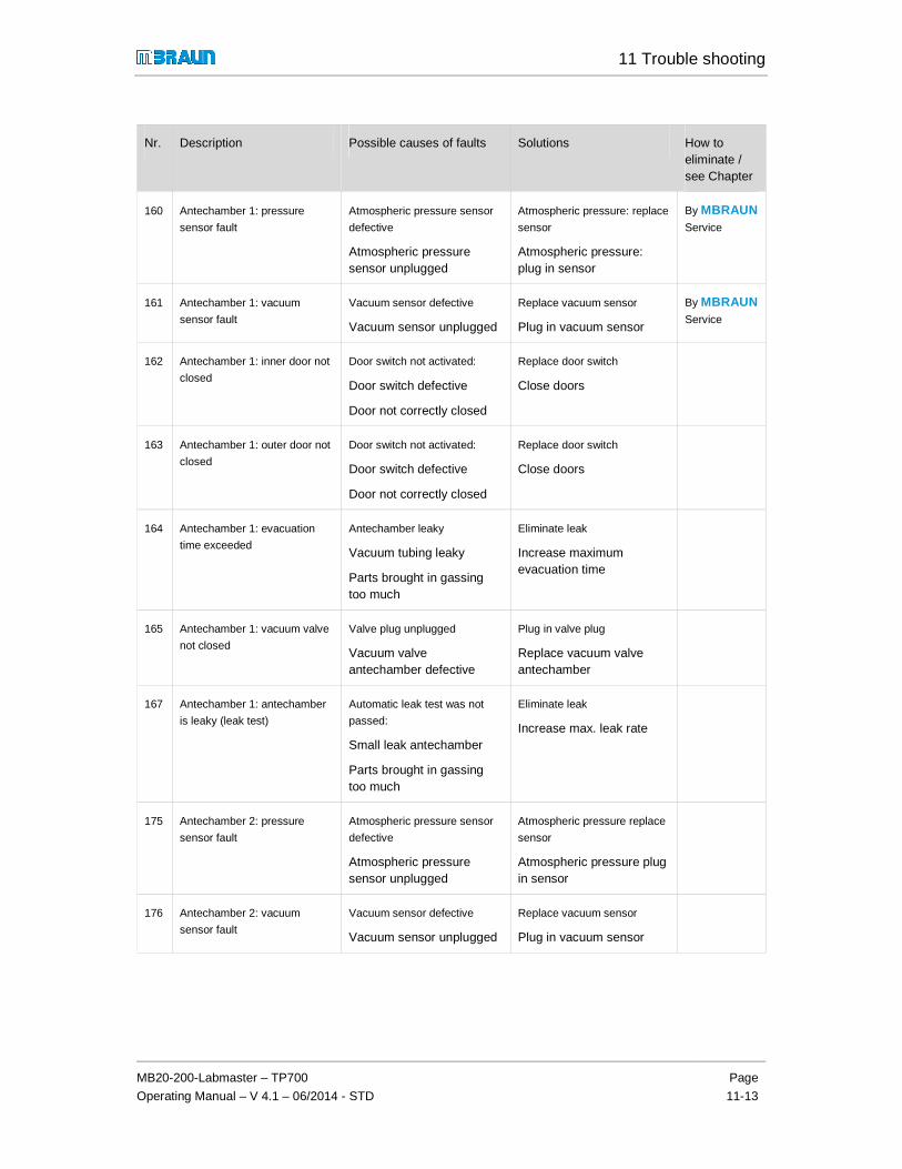
11 Trouble shooting
MB20-200-Labmaster – TP700
Operating Manual – V 4.1 – 06/2014 - STD
Page
11-13
Nr. Description Possible causes of faults Solutions How to eliminate / see Chapter
160 Antechamber 1: pressure
sensor fault Atmospheric pressure sensor
defective
Atmospheric pressure sensor unplugged
Atmospheric pressure: replace
sensor
Atmospheric pressure: plug in sensor
By MBRAUN
Service
161 Antechamber 1: vacuum
sensor fault Vacuum sensor defective
Vacuum sensor unplugged
Replace vacuum sensor
Plug in vacuum sensor
By MBRAUN
Service
162 Antechamber 1: inner door not
closed Door switch not activated:
Door switch defective
Door not correctly closed
Replace door switch
Close doors
163 Antechamber 1: outer door not
closed Door switch not activated:
Door switch defective
Door not correctly closed
Replace door switch
Close doors
164 Antechamber 1: evacuation
time exceeded Antechamber leaky
Vacuum tubing leaky
Parts brought in gassing too much
Eliminate leak
Increase maximum evacuation time
165 Antechamber 1: vacuum valve
not closed Valve plug unplugged
Vacuum valve antechamber defective
Plug in valve plug
Replace vacuum valve antechamber
167 Antechamber 1: antechamber
is leaky (leak test) Automatic leak test was not
passed:
Small leak antechamber
Parts brought in gassing too much
Eliminate leak
Increase max. leak rate
175 Antechamber 2: pressure
sensor fault Atmospheric pressure sensor
defective
Atmospheric pressure sensor unplugged
Atmospheric pressure replace
sensor
Atmospheric pressure plug in sensor
176 Antechamber 2: vacuum
sensor fault Vacuum sensor defective
Vacuum sensor unplugged
Replace vacuum sensor
Plug in vacuum sensor

11 Trouble shooting
Definition of the alarm and warning messages (PLC)
Page
11-14
MB20-200-Labmaster – TP700
Operating Manual – V 4.1 – 06/2014 - STD
Nr. Description Possible causes of faults Solutions How to eliminate / see Chapter
177 Antechamber 2: inner door not
closed Door switch not activated:
Door switch defective
Door not correctly closed
Replace door switch
Close doors
178 Antechamber 2: outer door not
closed Door switch not activated:
Door switch defective
Door not correctly closed
Replace door switch
Close doors
179 Antechamber 2: evacuation
time exceeded Antechamber leaky
Vacuum tubing leaky
Parts brought in gassing too much
Eliminate leak
Increase maximum evacuation time
180 Antechamber 2: vacuum valve
not closed Valve plug unplugged
Vacuum valve antechamber defective
Plug in valve plug
Replace vacuum valve antechamber
182 Antechamber 2: antechamber
is leaky (leak test) Automatic leak test was not
passed:
Small leak antechamber
Parts brought in gassing too much
Eliminate leak
Increase max. leak rate
203 Box pressure control valve
VDA not open Control valve defective
Control pressure too low
Replace valve
Set control pressure to 6 bar
205 Box pressure control error - Operator notice Contact MBRAUN Service By MBRAUN
Service
206 Regeneration error - Operator notice Contact MBRAUN Service By MBRAUN
Service
207 Box valves box 1 not open Box valves defective
Control pressure too low
Replace box valve
Set control pressure to 6 bar
By MBRAUN
Service
208 Box valves box 2 not open Box valves defective
Control pressure too low
Replace box valve
Set control pressure to 6 bar
By MBRAUN
Service

11 Trouble shooting
MB20-200-Labmaster – TP700
Operating Manual – V 4.1 – 06/2014 - STD
Page
11-15
Nr. Description Possible causes of faults Solutions How to eliminate / see Chapter
210 System not ready (no box
preselected) Both box valves closed:
Box not switched on activated
Box valves defective
Control pressure too low
Activate one or more boxes
Replace box valves
Set control pressure to 6 bar
212 Box pressure sensor defective Box pressure sensor defective
Box pressure sensor unplugged
Replace box pressure sensor
Plug in box pressure sensor
213 Box pressure is too low Vacuum valve gas purifier
does not close
Vacuum valve antechamber does not close
Refill valve antechamber is not closed
Replace defective valve
214 Box pressure is too high Pressure line in the box leaky
or torn
Purge gas flow rate too high with automatic purge
Eliminate leak in the gas
supply
Limiting of purge gas flow rate
215 Box temperature is too high Box cooling does not work:
Box cooling unplugged
Box cooling compressor defective
Plug in box cooling
Check/replacement of compressor by MBraun Service
MBRAUN Service
216 Box cooling: fault temperature
sensor Temperature sensor defective
Temperature sensor unplugged
Replace temperature sensor
Plug in temperature sensor

11 Trouble shooting
Definition of the alarm and warning messages (PLC)
Page
11-16
MB20-200-Labmaster – TP700
Operating Manual – V 4.1 – 06/2014 - STD
Nr. Description Possible causes of faults Solutions How to eliminate / see Chapter
217 Temperature refrigerator is too
high Cooling does not work:
Cooling has been deactivated
Door is leaky
Cooling compressor defective,
Increase temperature and wait
for stabilisation of the
temperature level Check for obstacles; Check O-rings Remove and/ or replace
Replacement compressor by MBraun Service
MBRAUN Service /
HVAC
technician
218 Refrigerator: fault temperature
sensor Temperature sensor defective
Temperature sensor unplugged
Replace temperature sensor
Plug in temperature sensor
220 Box pressure control error -
box open or glove tear Box open or glove tear Check box pane and gloves
for big leak, if necessary
contact MBraun Service
MBRAUN Service
221 Pressure sensors Box1 and
Box2: impermissibly high
measurement value difference
Zero point drift box pressure
sensors too high
Gas stream circulation Box1-Box2 differs
Perform zero point comparison
box pressure sensors
HEPA filter Box1 - Box2 soiled to different degrees
MBRAUN Service
225 Box pressure sensor Box 2
defective Box pressure sensor defective
Box pressure sensor unplugged
Replace box pressure sensor
Plug in box pressure sensor
MBRAUN Service
226 Box pressure Box 2 is too low Vacuum valve gas purifier
does not close
Vacuum valve antechamber does not close
Refill valve antechamber is not closed
Replace defective valve MBRAUN Service
227 Box pressure Box 2 is too high Pressure line in the box leaky
or torn
Purge gas flow rate too high with automatic purge
Eliminate leak in the gas
supply
Limiting of purge gas flow rate
MB20-200-Labmaster – TP700
Operating Manual – V 4.1 – 06/2014 - STD
11.5 Recommissioning
11.5.1 Normal flow regeneration
Step Time
0
Start 0 min.
1
2
3
4 – [16]
17 MB200 after 960 Min. [MB300:
11.5.2 Regeneration of the gas purifier RKM
Case Interruption in case of power failure
1 Cancellation in step 1 (regeneration gas check)
2 Cancellation in steps 3 – 7
3 Power failure duringstep 3 or 4:
4 Power failure during steps 5 … 16:
11 Trouble shooting
STD
Recommissioning after cancellation and power failure
Normal flow regeneration
Time Action – STD
Start 0 min. Regeneration deactivated
Test regeneration gas ON
Test regeneration gas OFF
Flow of regeneration in various steps
MB200 after 960 Min. MB300: after 1200 min.]
Regeneration ended
Regeneration of the gas purifier RKM
Interruption in case of power On return of power:
Cancellation in step 1 (regeneration gas check)
Unchanged -> jump to step 8 -> evacuation/refill cycles with shortened times (ges. 20 min)
Cancellation in -> jump to step 8 -> evacuation/refill cycles with standard times, in order to guarantee cooling off of the reactor (regardless of the heating time already elapsed)
Power failure during After return of power, the regeneration is continued at the beginning of step 3, that is, the complete heatup phase of the regeneration process is run through again
Power failure during
After return of power, the regeneration is continued at exactly the point interrupted (no jump back to the beginning of the current step).
Trouble shooting
Page
11-17
power failure
Flow of regeneration in various steps
> evacuation/refill cycles with shortened times (ges. 20 min)
> evacuation/refill cycles with standard times, in order to guarantee cooling off of the reactor (regardless of the heating time already
he regeneration is continued at the beginning of step 3, that is, the complete heat-up phase of the regeneration process is run through
After return of power, the regeneration is continued nterrupted (no jump back to the

11 Trouble shooting
Error search: leak test
Page
11-18
MB20-200-Labmaster – TP700
Operating Manual – V 4.1 – 06/2014 - STD
11.5.3 Regeneration of the gas purifier LMF
A cancellation of the regeneration programme is only possible in step 1 (without security question "Cancel yes/no"). There is a jump to the last step since no evacuation/refill cycles are necessary (RegGas = N2)
11.6 Error search: leak test
A leak test on the system is required
� On recommissioning
� With unexplained increase of the O2 content in the box
� Unexplained pressure increase/drop in the box
This procedure can be performed by MBRAUN Service.
Training leak test procedure
MBRAUN offers a training of the operating personnel for performing the leak test. Please contact MBRAUN service.

12 Inspection and maintenance
MB20-200-Labmaster – TP700
Operating Manual – V 4.1 – 06/2014 - STD
Page
12-1
12.1 Introduction ...................................... .................................................... 12-2 12.1.1 Inspection and maintenance work ........................................................................ 12-3
12.1.1.1 Standard system.............................................................................................. 12-3 12.1.1.2 Optional components ....................................................................................... 12-3 12.1.1.3 Components of third-party manufacturers ....................................................... 12-3
12.1.2 Maintenance contract with MBRAUN ................................................................... 12-3
12.2 Safety during maintenance and inspection work ..... ......................... 12-4
12.3 Overview of cyclical inspection and maintenance wor k ................... 12-8
12.4 Preparation for inspection and maintenance work ... ....................... 12-10 12.4.1 Basic work .......................................................................................................... 12-10 12.4.2 Shutting down the system .................................................................................. 12-10 12.4.3 De-energise system (for work on open system/on the electrical system) ........... 12-11 12.4.4 Preparing opening of the box – fill box with ambient air ..................................... 12-12
12.5 Maintenance work .................................. ............................................ 12-13 12.5.1 Maintenance of inert gas box ............................................................................. 12-13 12.5.2 Gloves ................................................................................................................ 12-14
12.5.2.1 Method 1: with interior sealing cover ............................................................. 12-16 12.5.2.2 Method 2: without interior sealing cover ........................................................ 12-19
12.5.3 Replacing particle filter in the box ...................................................................... 12-21 12.5.4 Calibrate/clean sensors ...................................................................................... 12-22
12.5.4.1 Send oxygen sensor MB-OX-SE1 in for calibration ....................................... 12-22 12.5.4.2 Cleaning MB-MO-SE-1 moisture sensor – while the system is in operation .. 12-23
12.5.5 Box cooling / refrigerator (optional) .................................................................... 12-27 12.5.6 Antechamber ...................................................................................................... 12-27 12.5.7 Vacuum pump .................................................................................................... 12-27 12.5.8 Gas purification purifier ...................................................................................... 12-27 12.5.9 Solvent filter LMF (Option) ................................................................................. 12-28 12.5.10 PLC controller .................................................................................................... 12-30
12.6 Completing maintenance – recommissioning........... ....................... 12-30
12.7 Function tests .................................... ................................................ 12-31 12.7.1 Electrical test ...................................................................................................... 12-31
12.8 Disposal of replaced components ................... ................................. 12-31
12.9 Return of components .............................. ......................................... 12-31

12 Inspection and maintenance
Introduction
Page
12-2
MB20-200-Labmaster – TP700
Operating Manual – V 4.1 – 06/2014- STD
12 Inspection and maintenance
12.1 Introduction
In order to maintain a high safety standard for a closed inert gas system, regular inspection and maintenance of the complete system is required – including the integrated additional components of third-party manufacturers (cf. Chap. 6 Operating modes).
During the inspection and maintenance work, the closed circuit between external media connections, inert gas box and the gas purifier is interrupted.
This is associated with specific risks, which depend on the type and degree of hazard of the process materials used in the system. Please heed Chapter 4 Installation and the following section about "Safety".
Documenting inspection and maintenance
Carefully adhere to the inspection and maintenance intervals and document all work in the service and maintenance log.
Spare parts kit
In order to prevent production breakdowns, you should keep spare parts on hand for unplanned maintenance work so that they are constantly available (such as gloves, sensors, etc. see Chap. 14 Spare parts).
Who may do what?
Qualified + trained personnel
Qualified electrical engineer
Qualified HVAC
technician
Only MBRAUN Service
Intervention in the PLC controller
X
Electrical components X
Electrical-pneumatic components
X X
Cooling unit X
Maintenance work according to operating manual
X
Repair and maintenance work not described in the operating manual
X

12 Inspection and maintenance
MB20-200-Labmaster – TP700
Operating Manual – V 4.1 – 06/2014 - STD
Page
12-3
12.1.1 Inspection and maintenance work
12.1.1.1 Standard system
For standard systems, regular inspections must be performed of the main components gas purifier, box, antechamber and vacuum pump. For an overview, see Chap. 12.3.
Always perform after completing inspection and maintenance work:
► Function checks with - electrical test - leakage test
12.1.1.2 Optional components
MBRAUN inert gas systems can be equipped with optional additional components, for example:
� Universal measurement device
� Refrigerator, box cooling
Heed the maintenance and care instructions
See chapter for the optional components (7-9 A.. or 10 A..)
12.1.1.3 Components of third-party manufacturers
Some MBRAUN inert gas systems can be equipped with components from third-party manufacturers, for example:
� Vacuum pump(s)
� Compressor(s) for system cooling
� Compressor(s) for freezers
The original supplier documentation that describes the inspection and maintenance of these components is a component of the scope of delivery. See Chap. 14 Supplier documentation
WARNING
Risk of injury and damage!
► Heed all third-party technical documents during maintenance work.
12.1.2 Maintenance contract with MBRAUN
Optionally a maintenance contract can be signed with MBRAUN .
Please contace M. Braun service to discuss maintenance contract options.

12 Inspection and maintenance
Safety during maintenance and inspection work
Page
12-4
MB20-200-Labmaster – TP700
Operating Manual – V 4.1 – 06/2014- STD
12.2 Safety during maintenance and inspection work
Please note that the degree of hazard for inspectio n and maintenance work depends on the type of gases and process materials used.
The requirements and maintenance cycles named in this operating manual refer to minimum requirements for standard systems without the use of hazardous process materials.
Standard flow plan
MBRAUN recommends adapting the inspection and maintenance work to the specific conditions if necessary and integrating these into a specific standard flow plan for the process materials used and conditions on-site.
Adhering to maintenance cycles
DANGER
Risk of health and environmental damage due to material damage in case of non-adherence to maintenance cycles
The degree of hazard depends on the gases and process materials used.
► Adhere to the inspection and maintenance cycles
► Integrate the maintenance cycles into your operation-specific flow plan
If the inspection and maintenance cycles are not adhered to, all warranty and liability claims against MBRAUN are voided.
Qualification of personnel
WARNING
Risks to people and the environment due to improperly-performed inspection and maintenance work.
► Only qualified and trained personnel may perform inspection and maintenance work
► Follow the instructions in this operating manual
► Maintenance work that is not described in this operating manual may only be performed by MBRAUN service technicians or specially-trained personnel (HVAC technicians, electricians, qualified electro-pneumatic technicians -- see overview).
In case of improper inspection and maintenance cycles, all warranty and liability claims against MBRAUN are voided.

12 Inspection and maintenance
MB20-200-Labmaster – TP700
Operating Manual – V 4.1 – 06/2014 - STD
Page
12-5
Risk of suffocation
DANGER
Risk of suffocation or health hazards when opening boxes under inert gas atmosphere!
► Do not breathe in inert gases!
Always ensure good ventilation of the room
When opening panes and doors, make sure:
► to adhere to the flow for preparation of maintenance work (Chap. 12.4)
► The oxygen content in the box is more than 19.5 %
Electrical hazards
DANGER
Risk to people due to electrical shock in case of improper handling of electrical components!
� Only trained and qualified electricians may perform work on electrical components of the system!
Before starting work on the control cabinet and/or electrical components:
► Switch off the system with the main switch
► Remove the system from the mains
► Secure the system against undesired switching on
! Exceptions:
Particular maintenance work and functional tests can be performed when the power supply is switched on (replacement of sensors, filters, gloves) as long as no hazardous processes/process materials are used.
Heed the notes in this operating manual.

12 Inspection and maintenance
Safety during maintenance and inspection work
Page
12-6
MB20-200-Labmaster – TP700
Operating Manual – V 4.1 – 06/2014- STD
Hazard due to process materials and gases
DANGER
Health and environmental risks due to gases, processes and process materials used!
Gases, processes and process materials used can, in contact with oxygen, be easily flammable, explosive, toxic or present a risk to health and the environment. They can react with one another and form unintended and unknown substances.
Before beginning maintenance work in the box
► Mark all containers and supply lines that contain hazardous process materials
► Remove all hazardous process materials (in closed containers) from the box
► Handle all components that come into contact with process materials carefully (filter material for solvent filters, particle filters, sensors, etc.)
► Depending on the requirements, wear personal protective equipment (e.g. complete
safety mask, protective gloves, safety goggles)
► Dispose of all contaminated components of the system properly according to the locally-applicable regulations.
Removal of particle filters and sensors when the sy stem is switched off
DANGER
Personal injury and environmental damage due to contamination through hazardous processes/process materials!
Sensors and particle filters are constantly subjected to the gas flow in the box/the gas purifier. When using hazardous materials in the inert gas box, people and the environment are at risk!
Before removing sensors and particle filters:
► Purge box / pipework
► Switch off system!
► Clean box
► Follow the description in Chapter 12.4 Preparing maintenance and inspection work
Depending on the application and degree of hazard of the processes/process materials, constructive and functional additional equipment may be necessary.
Contact MBRAUN Service.
Only use for standard systems with non-hazardous pr ocesses and process materials:
Maintenance work during operation of the system

12 Inspection and maintenance
MB20-200-Labmaster – TP700
Operating Manual – V 4.1 – 06/2014 - STD
Page
12-7
For maintenance work during operation of the system – as for replacement of gloves, sensors or particle filters – ambient air can penetrate the system through the open flange. Box atmosphere can get into the ambient air.
NOTICE
During dismounting of the sensors, the contamination of the box atmosphere with ambient air must be avoided!
► Always work quickly and without interruption
► Follow the description in the operating manual

12 Inspection and maintenance
Overview of cyclical inspection and maintenance work
Page
12-8
MB20-200-Labmaster – TP700
Operating Manual – V 4.1 – 06/2014- STD
12.3 Overview of cyclical inspection and maintenance work
The specifications of the intervals are minimum specifications. Depending on the processes/process materials used, shorter intervals may be necessary.
*) Only by MBRAUN Service **) Only trained HVAC technicians
**) Only trained electricians
Mon
thly
Qua
rter
ly
Sem
i-an
nual
ly
Ann
ually
Oth
er
See
cha
p.
Inertgas box
Clean sensor (H2O sensor) x
Calibrate sensors (O2 sensor) x see 12.5.1.2
MBRAUN Service
Check to make sure that all connections are tight and free of contamination and damage
x
Check omega seals of the box windows
x
Check magnetic valves x
Perform complete leak test x
Perform function test x
Check lighting x
Check and if necessary replace magnetic valves
x
Check general state of gloves and check for tears.
x
Replace gloves x Or as
needed
Replace particle filters x

12 Inspection and maintenance
MB20-200-Labmaster – TP700
Operating Manual – V 4.1 – 06/2014 - STD
Page
12-9
Mon
thly
Qua
rter
ly
Sem
i-an
nual
ly
Ann
ually
Oth
er
See
cha
p.
Antechamber
Check to make sure that all connections are tight and free of contamination and damage
x
Check antechamber seals for damage
x
Replace sealing rings if
necessary
Optional: safety valve test 0.1 bar / 0.3 bar
x
Vacuum Pump
Connection of the vacuum pump: sealing rings
Check functionality of the valves
Gas purifier
Check to make sure that all connections are tight and free of contamination and damage
x
Check magnetic valves x
Test blower x
Test vacuum pump x
Perform function test x
Test blower, replace if necessary x
Test purification unit x
Replace purifier filling if
necessary
*)
Check and if necessary replace valve seals
x
Test cooling system **)
Check coolant **)
LMF
Replace filter medium (active carbon) x x 12.6.9
! Note also the details about maintenance in the chapter for the additional components (Chap. 7 -9 A..X) as well as the additional equipment (Chap. 10 A..X).

12 Inspection and maintenance
Preparation for inspection and maintenance work
Page
12-10
MB20-200-Labmaster – TP700
Operating Manual – V 4.1 – 06/2014- STD
12.4 Preparation for inspection and maintenance work
12.4.1 Basic work
1 ► Preparations:
- Provide all required spare parts (gloves, particle filters, sensors, etc.)
- Provide personal protective equipment, insofar as required
- Provide cleaning materials (cleaning agents, cloths, waste containers)
- Provide containers for the proper disposal of replaced components
2 Ensure good ventilation of the room
3 ► Unload sensitive/hazardous process materials (in closed containers).
WARNING Depending on the type and degree of hazard of the process materials used: if necessary, heed all safety-relevant requirements of your process-specific standard flow plan
12.4.2 Shutting down the system
1 ► Deactivate all processes: - of the integrated additional components - of the system (no antechamber processes active, no regeneration active)
2 ► Switch off circulation
3 ► Switch off sensors for O2 and H2O
4 ► Close external gas feed
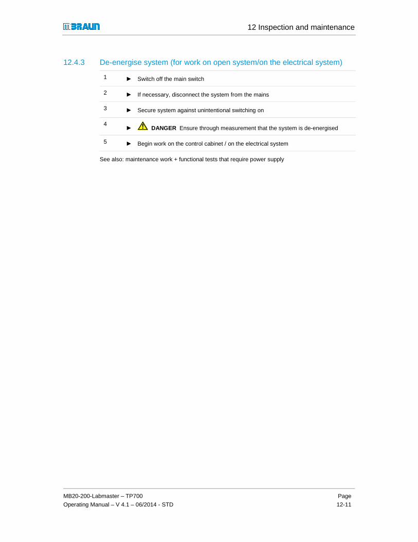
12 Inspection and maintenance
MB20-200-Labmaster – TP700
Operating Manual – V 4.1 – 06/2014 - STD
Page
12-11
12.4.3 De-energise system (for work on open system/on the electrical system)
1 ► Switch off the main switch
2 ► If necessary, disconnect the system from the mains
3 ► Secure system against unintentional switching on
4 ► DANGER Ensure through measurement that the system is de-energised
5 ► Begin work on the control cabinet / on the electrical system
See also: maintenance work + functional tests that require power supply

12 Inspection and maintenance
Preparation for inspection and maintenance work
Page
12-12
MB20-200-Labmaster – TP700
Operating Manual – V 4.1 – 06/2014- STD
12.4.4 Preparing opening of the box – fill box with ambient air
Prerequisite
> Heed the safety chapter 3
> Heed the safety instructions in this chapter for maintenance and inspection work.
> The set-up conditions (ventilation of the room!) are adhered to (see Chap. 4.3.1)
> Preparatory work has been performed (Chap. 12.4.1- 12.4.2)
> For electrical work inside the box: Chap. 12.4.3
WARNING Before beginning maintenance work in the box/before opening the box
(inner antechamber door, window, gloves), the box must be filled with ambient air up to an oxygen content of at least 19.5 %.
a) Standard boxes / antechambers with a total volume up to 6 m³ (only with use of non-hazardous gases (N2) and process materials):
Let box/antechamber atmosphere (with good room ventilation!) escape slowly:
1. First open outer antechamber door and let atmosphere escape slowly
2. Open inner antechamber door
3. Wait appropriately depending on the box volume.
4. Ensure sufficient ventilation of the room
5. The box windows/doors can be opened
b) Special systems: with use of large-volume boxes, ha zardous gases and process materials:
DANGER The replacement of the box/antechamber atmosphere may only be done with a connected exhaust air system!
Optional: The feed of ambient air should be done using an MBRAUN air purge unit
Before opening box windows/doors:
► Measure the oxygen content within the box using the test flange;
► If O2 content is greater than 19.5%: the box windows/doors can be opened
► Perform maintenance work

12 Inspection and maintenance
MB20-200-Labmaster – TP700
Operating Manual – V 4.1 – 06/2014 - STD
Page
12-13
12.5 Maintenance work
Prerequisites:
> Preparatory work has been performed (See above, section 12.4)
12.5.1 Maintenance of inert gas box
Remedy for error messages (see Chap. 11):
� Pressure line in the box leaky or torn: eliminate leak
� Defective vacuum valve gas purifier/antechamber: replace vacuum valve
� Defective refill valve antechamber: replace refill valve
� Defective box valve: replace box valve
� Pressure indicator error: plug in/replace box pressure sensor
Cleaning the box window
Clean with customary cleansers (no aggressive or caustic cleansers).
Use a soft, lint-free cloth or vacuum cleaner with soft cleaning brush.
System with integrated MBRAUN vacuum cleaner system :
The vacuum cleaner system can be used with a brush attachment for cleaning the inside of the window.

12 Inspection and maintenance
Maintenance work
Page
12-14
MB20-200-Labmaster – TP700
Operating Manual – V 4.1 – 06/2014- STD
12.5.2 Gloves
Basic rules
� Heed the basic rules for inspection in the inert gas box chapter while using the gloves.
� Always keep a set of gloves, O-rings and glove sealing cover ready for an unplanned change (see Chap. 14 Spare parts)
� All gloveport feedthroughs may never be sealed at the same time!
� Recommendation: Train the glove change regularly so that in case of error during ongoing operation you can replace the gloves quickly and safely
� With the use of sensitive processes or those that endanger health or the environment: additional equipment for redundant safety is required! (see Chap. 4. Installation)Specify the procedure in your operation-specific standard flow plan.
� Keep the appropriate personal protective equipment (PPE) on hand.
WARNING
Ambient air penetrates the box due to damaged gloves and disturbs the inert gas atmosphere. The box atmosphere can escape and cause personal injuries.
Depending on the gases and processes/process materials used, there can be material damage and/or personal injury (risk of suffocation!).
Never repair and reuse damaged gloves!
► Damaged gloves must always be replaced with new ones!
► Replace worn and defective gloves immediately!
Regular care
Only outside of the gloves (user's side):
► Sprinkle with a little talcum powder
NOTICE
Do not use any talcum powder:
� Box-side, on the inside of the gloves
� In cleanrooms!

12 Inspection and maintenance
MB20-200-Labmaster – TP700
Operating Manual – V 4.1 – 06/2014 - STD
Page
12-15
Replace gloves
The process differs depending on the type of processes/process materials used. MBRAUN recommends the following application types:
Application glove change
In o
ngoi
ng o
pera
tion
With
box
out
of
serv
ice
/ Box
is u
nder
am
bien
t ai
r
Glo
ve c
hang
e w
ith
seal
ing
cove
r
Glo
ve c
hang
e w
ithou
t se
alin
g co
ver
Standard (non-sensitive, non-hazardous processes/process materials)
x x
Standard (sensitive materials) (X) x (X) x
Replacement of several gloves for large-volume (MOD) boxes
x x
DANGER With the use of processes/process materials that present a hazard to health or the environment:
There are special instructions for gloves and gloveport feedthroughs with deviating methods of changing gloves (see special chapter 8 A.. / 10 A.. "Oval gloveport feedthroughs").
Preparation (Material + Box)
Preparing material:
- Glove sealing cover
- Make sure that the right gloves are used.
- With anatomical gloves, mark the right and left glove
- If necessary wear personal protective equipment
! MBRAUN recommends keeping on hand a parts kit with the most important measurement devices and spare parts: for example, measurement devices such as leak testers, spare gloves, outer sealing covers, etc.

12 Inspection and maintenance
Maintenance work
Page
12-16
MB20-200-Labmaster – TP700
Operating Manual – V 4.1 – 06/2014- STD
1. Preparation of the box:
A Regular change with the box out of operation (wit h the use of gases, processes/process materials hazardous to health or the environment)
Take box out of operation:
- End processes
- Purge box
- Switch system OFF
- Close gas connections
- Fill box with ambient air
B Regular change in ongoing operation
(only with use of process/process materials that do not endanger health and the environment)
► Prepare the glove change carefully
► Work quickly and without interruption
► Load glove sealing cover into the box
► Unload sensitive materials or keep in the antechamber in the box during the glove change
► Ensure good ventilation of the room
Preparing status box:
► Put box in slight over pressure (approx. 1 - 2 mbar)
12.5.2.1 Method 1: with interior sealing cover
NOTICE
Undesired pressure increase in the box!
► For glove change in ongoing operation: All gloveport feedthroughs may never be sealed at the same time!

12 Inspection and maintenance
MB20-200-Labmaster – TP700
Operating Manual – V 4.1 – 06/2014 - STD
Page
12-17
Attach inner sealing cover either through the gloveport feedthrough whose gloves should be replaced (knob is then outside) or through another gloveport feedthrough (knob is then inside).
Gloveport feedthrough is sealed.
Remove both O-rings from the gloveport feedthrough
Remove glove
Roll new glove on firmly so that as little air as possible remains in the new glove.

12 Inspection and maintenance
Maintenance work
Page
12-18
MB20-200-Labmaster – TP700
Operating Manual – V 4.1 – 06/2014- STD
NOTE: Place anatomical gloves in the correct position.
Place new, rolled-on glove in the (sealed) gloveport feedthrough.
Put new glove onto the gloveport feedthrough up to the inner notch.
Align glove correctly on the gloveport feedthrough
Secure glove onto the outer two notches of the gloveport feedthrough with two new O-rings.
Remove inner sealing cover.
Putting the box back into operation:
After the glove change:
► Purge inert gas box. See Chapter 8.5 Inertising the box.
► As soon as the oxygen and moisture content is less than 100 ppm, the box may be put back into circulation operation.
! To dispose of used gloves: follow Chap. 12.8

12 Inspection and maintenance
MB20-200-Labmaster – TP700
Operating Manual – V 4.1 – 06/2014 - STD
Page
12-19
12.5.2.2 Method 2: without interior sealing cover
► Put inert gas box in slight over pressure (approx. 1 - 2 mbar)
Push new glove into the old glove.
NOTE: Make sure that both gloves lie precisely in one another so that there is as little air as possible between the gloves.
Remove both O-rings from the gloveport feedthrough.
Pull old glove off the gloveport feedthrough and
IMMEDIATELY
put new glove over it.
Pull glove on the gloveport feedthrough up to the inner notch and align correctly.
Only secure new glove first with a new O-ring on the inner notch of the gloveport feedthrough.

12 Inspection and maintenance
Maintenance work
Page
12-20
MB20-200-Labmaster – TP700
Operating Manual – V 4.1 – 06/2014- STD
Pull off old glove from inside
Then secure new glove with a second new O-ring on the outer notch of the gloveport feedthrough.
Unload old glove.
Putting the box back into operation:
After the glove change, remove unwanted oxygen and moisture remains:
► Purge inert gas box (manually)See Chapter 8.5 Inertising the box
! To dispose of used gloves: follow Chap. 12.8

12 Inspection and maintenance
MB20-200-Labmaster – TP700
Operating Manual – V 4.1 – 06/2014 - STD
Page
12-21
12.5.3 Replacing particle filter in the box
NOTICE
With saturated box filter, there can be contaminati on/disturbance of the box atmosphere and of the process materials as well as an increase in box pressure!
► Replace saturated filters in timely fashion
► Used filters may not be reused!
DANGER with use of hazardous process materials in the box:
Preparation
> Prepare new filter
> Place filter in a closed container
In ongoing operation:
Carefully pull out used filter unit
Place in a container that can be sealed
Unload and dispose of properly.
Carefully clean box of loose particles
Load new filter
Put on new filter and screw in

12 Inspection and maintenance
Maintenance work
Page
12-22
MB20-200-Labmaster – TP700
Operating Manual – V 4.1 – 06/2014- STD
12.5.4 Calibrate/clean sensors
WARNING
The sensor is constantly subjected to the gas flow. With the use of hazardous materials in the inert gas box, there is the risk of a contamination.
The exchange process described here is not suitable for the use of hazardous materials.
► Contact MBRAUN for additional functions/equipment
For the removal of used sensors:
► If necessary wear personal protective equipment (PPE)
► Place the sensor in a container that can be sealed immediately after removal
► Dispose of used sensors according to all applicable local and national safety guidelines for the handling of potentially-contaminated material
Send used sensors to MBRAUN :
► Use the decontamination declaration
► Be sure to follow the instructions (see attachment to this chapter)
12.5.4.1 Send oxygen sensor MB-OX-SE1 in for calibration
The oxygen sensor MB-OX-SE1 is maintenance-free. MBRAUN recommends (at least) an annual calibration of the oxygen sensor. The calibration cycles depend on the use of the measurement devices and the gases used (purity, trace gases, etc.).
Removing the O2 sensor (standard systems – only with use of non-hazardous materials
Only with use of non-hazardous materials: replace during operation of the system
Preparations
> Provide a new oxygen sensor MB-OX-SE1
> If necessary wear personal protective equipment
Status system
► Switch off O2 sensor on the touch panel
► Bring box pressure to a value between +1.0 and +5.0 mbar
► Switch off circulation operation

12 Inspection and maintenance
MB20-200-Labmaster – TP700
Operating Manual – V 4.1 – 06/2014 - STD
Page
12-23
Replacing the oxygen sensor
CAUTION WORK QUICKLY AND WITHOUT INTERRUPTION!
► Open the securing clamp
► Remove the used O2 sensor
► Insert the new O2 sensor
! After an exposure to the ambient air, it can take several hours until the sensor provides accurate measurement values about inert gas conditions again.
► Reset box pressure to normal pressure
► Switch on circulation operation
► Activate sensor on the touch panel
► Contact MBRAUN Service for calibration.
12.5.4.2 Cleaning MB-MO-SE-1 moisture sensor – while the system is in operation
NOTICE
Insufficient maintenance of the moisture sensor causes imprecise measurements and compromises the cleanliness of the box atmosphere, after 2000 hours of operation a cleaning of the sensor is necessary!
► Clean the moisture sensor at the latest when asked to do so by the pop-up menu on the touch panel(See chapters inert gas box, sensor monitoring of the inert gas atmosphere).
Cleaning the sensor
WARNING
Personal injuries due to chemical burns to the skin and the eyes with use of phosphoric acid as cleanser!
► Wear protective gloves and goggles!
► In case of contact with phosphoric acid, rinse skin immediately with running water.
► If phosphoric acid gets in the eyes: Rinse eyes immediately with running water.
► Contact a physician immediately.

12 Inspection and maintenance
Maintenance work
Page
12-24
MB20-200-Labmaster – TP700
Operating Manual – V 4.1 – 06/2014- STD
Preparation:
> soft, absorbent, lint-free cloth (cotton) / absorbent household paper
> distilled water
> small quantity of 85% phosphoric acid (H3PO4) .
> blind cover for sealing the circulation pipework (DN40)
> protective clothing, incl. protective gloves and goggles
1 2
Unplugging the sensor cable
1 Moisture sensor with cable
2 Unplug connector
3
4
Dismounting the sensor
3 Loosen clamp
4 Remove sensor
5 6
Sealing pipework with blind flange
5 Put on blind cover
6 Attach flange clamp

12 Inspection and maintenance
MB20-200-Labmaster – TP700
Operating Manual – V 4.1 – 06/2014 - STD
Page
12-25
7 8
Removing the protective cap
7 Unscrew carefully
8 Carefully remove the protective cap
Distilled water 9 + 10
Cleaning the sensor
9 Moisten sensor with distilled water
10 Carefully clean and dry sensor with the cloth
85% phosphoric acid H3PO4 11
Moistening the sensor
11 Moisten sensor completely with a thin coating of phosphoric acid.
Screw on the protective cap
12 Screw the protective cap back on

12 Inspection and maintenance
Maintenance work
Page
12-26
MB20-200-Labmaster – TP700
Operating Manual – V 4.1 – 06/2014- STD
Install the moisture sensor
The installation of the moisture sensor takes place in reverse order (see above, steps 1-6):
► Remove clamp and blind cover
► Insert sensor
► Fasten sensor with the clamp
► Plug in sensor plug
Operating hours reset moisture sensor
After cleaning the sensor, reset the operating hours:
► Call up Maintenance of H2O sensor from the General Parameters screen.
Service O2 sensor 01705
"Operating hours" field
► Touch the Reset button
! After fresh moistening and an exposure to the ambient air, it can take two to six hours until the moisture sensor provides accurate measurement values about inert gas conditions again.

12 Inspection and maintenance
MB20-200-Labmaster – TP700
Operating Manual – V 4.1 – 06/2014 - STD
Page
12-27
12.5.5 Box cooling / refrigerator (optional)
! Maintenance may only be performed by a trained HVAC technician!
12.5.6 Antechamber
► Check regularly:
� Sealing rings for soiling/damage/material fatigue
� Locking mechanism for easy running
� Connection of the vacuum pump: sealing rings
� Functionality of the valves
► Grease sticky antechamber doors slightly with vacuum grease
► Replace sealing rings
! Some areas must remain free of lubricants.
� Never use lubricants inside the box!
12.5.7 Vacuum pump
See supplier documentation
12.5.8 Gas purification purifier
Maintenance work on gas purification purifiers may only be performed by MBRAUN Service, especially
- Replacement of the purifier filling
- Replacement of the heater
- Replacement of the inlet/outlet valves

12 Inspection and maintenance
Maintenance work
Page
12-28
MB20-200-Labmaster – TP700
Operating Manual – V 4.1 – 06/2014- STD
12.5.9 Solvent filter LMF (Option)
Prerequisites:
! Heed the safety chapter 3 and the foregoing safety instructions in Chap. 12.2
Replacing the filter medium
MBRAUN recommends the replacement of the filter medium every 3-6 months. With frequent use of solvents, an earlier replacement may be necessary.
WARNING
Risk of personal injury and material and environmental damage due to remaining solvents/vapours during changing of the filter medium!
► Handle the replacement of the used filter medium with the greatest care
► Wear personal protective equipment (PPE): appropriate breathing protection full mask (with suitable filter), protective gloves and eye protection, clothing protection
►
► Inform your fire safety officer before changing the filter medium
► Keep suitable extinguishing agents on hand
! Active carbon LMF (absorption principle): Reliable operation of the solvent filter is only guaranteed with active carbon from MBRAUN (item no. 2182000).
Preparation:
Provide MBRAUN active carbon
Provide solvent-resistant container that can be sealed
Wear personal protective equipment
Changing the LMF filter medium:
1. Set valves: put solvent filter in bypass function
Setting the valves:
See valve scheme Gas purifier chapter 7.4.3
► Open valve 3

12 Inspection and maintenance
MB20-200-Labmaster – TP700
Operating Manual – V 4.1 – 06/2014 - STD
Page
12-29
► Close valve 1
► Close valve 2
► Put valve 4 in "closed" position.
2. Replace filter medium
► Open flange for emptying on the solvent filter (OUT) and catch the used filter medium in a container. Then close the flange.
► Open the flange for filling (IN) and fill with 5 kg active carbon. Then close the flange.
3. Evacuate and refill the solvent filter
! ► Put valve 4 in the EVACUATE position and
► leave in this position for 12+ hours
► After refilling, put the valve in the REFILL (REFILL) position until the manometer has reached the value "0"..
► Put valve 4 in the CLOSED (CLOSED) position. The solvent filter can be put back into circulation operation (see chap. Gas purifier solvent filter (LMF).

12 Inspection and maintenance
Completing maintenance – recommissioning
Page
12-30
MB20-200-Labmaster – TP700
Operating Manual – V 4.1 – 06/2014- STD
12.5.10 PLC controller
► Replace buffer battery (CR2032)
► Check tight fit of all clamps
► In case of error, it may be necessary to replace the controller: please contact MBRAUN Service.
12.6 Completing maintenance – recommissioning
Follow-up:
1 Establish current connection
2 Switch system on
3 Function checks - with power supply:
- Valves
- Sensors
4 Perform leak test on the system

12 Inspection and maintenance
MB20-200-Labmaster – TP700
Operating Manual – V 4.1 – 06/2014 - STD
Page
12-31
12.7 Function tests
12.7.1 Electrical test
After each change to the electrical systems / maintenance and repair, perform an electrical test.
Cyclical testing is due according to BGV A3 or in-house regulation.
► Document the test performed in your maintenance log.
12.8 Disposal of replaced components
! All replaced components must be disposed of properly according to local regulations without endangering health or the environment.
Solvent filter (active carbon)
The filter material of solvent filters (active carbon) can be contaminated by process chemicals and solvents.
► Heed the requirements from the safety data sheets (material data sheets) of the process materials used.
► Dispose of the filter material according to the locally-applicable national guidelines.
12.9 Return of components
Before parts can be sent to MBRAUN :
► Fill out the included "Decontamination declaration" form:
► First send the decontamination declaration to MBRAUN
► Await confirmation: MBRAUN Service will inform you whether the parts can be accepted
► Only send parts after receiving confirmation
! MBRAUN does not accept parts if
� Parts are sent without filled-out "Decontamination declaration" form and there is no initial confirmation from Service
� Contaminated parts are those that were in contact with substances that pose risks to health and the environment

Declaration about Decontamination
F3_09_02 Dekontaminationserklärung Version 004 Page 1/2
Legally binding declaration: We hereby assure that the information in this statement is complete & accurate. The transportation of the contaminated products must be carried out in accordance with legal requirements. We realize that we are liable to the MBraun Inc. for damages caused by incomplete and incorrect information.
Name of the authorized person (Please print)
Date Signature Company stamp
Pumps / valves
MB-MO-SE1H20
Always clean H2O sensor. Remove phosphoric acid. Clean with water
and dry it.
Was the part in use?
Was the part in contact with highly toxic, radioactive, explosive or biological active material?
Was the part in contact to chemically dangerous substances?
Carry out a professional decontamination. Fill out the material list. Send the declaration with a
authorized signature to M.Braun’s Service Dept. After review you will receive an RMA number.
All components except blowers,
pumps, valves and analyzers
Blowers
M.Braun Service will approve.
M.Braun Service sends the
manufacturer’s form. The
manufacturer will confirm, if a return
is possible.
After approval and receipt of an RMA number ship it to M.Braun:
MBRAUN INC.14 Marin Way
Stratham, NH 03885
Professionaly dispose, if a return is not possible
yes
yes
no
Nein
yes
Contact M.Braun Service
Coordinator about further action.
Professional dispose, if return is not possible.
Answer for M.Braun Service:return is possible
noyes
MB-OX-ECMB-OX-SE1MB-OX-SE3
O2
Remove the protective cover. If the sensorhead is
contaminated, unplug and dispose it.
Remove black cover. If
contaminated, dispose the EC cell
& clean sensorhead.
Send the declaration with an authorized signature to M.Braun Service department.
After review you will receive an RMA number.
no
no
Always clean H2O sensor
analyzers
Carry out the cleaning and confirm it on page 2.

Declaration about Decontamination
F3_09_02 Dekontaminationserklärung Version 004
Page 2/2
The service and repair of M.Braun glove boxes and their components can only be performed after presentation of this completed form. The completed declaration must have be checked by M.Braun Service before a part can be accepted. After review and approval of the declaration you will receive a return material authorization number (RMA number). Note: The shipment of contaminated parts may be a violation of national and international laws.
1. Project number / year of manufacturing 6. Company / institute
2. Type of component: blower, analyzer…. 7. Address
3. Type / name / serial number
4. Special equipment installed (e.g. LMF)
5. Reasons for return
List of hazardous materials and certification of decontamination Enter all hazardous materials which the component was in contact with. Please print:
Pos. CAS-Nr. Name of chemical Chemical formula Class of risk
1
2
3
4.
5.
6.
Hereby we assure that the component has been cleaned and it is not contaminated. Date Signature

13 Ersatzteile / Spare Parts / Pièces détachées
MB20-200-Labmaster – TP7
Operating Manual – V 4.1 – 06/2014 - STD
Seite
13-1
13.1 Gasreinigung / Gas Purifier / Purificateur de gaz Error! Bookmark not defined. 13.1.1 Standard: Vorderansicht / Front View / Vue de face .. Error! Bookmark not defined. 13.1.2 Rückansicht / Rear side / Vue arrière ......................... Error! Bookmark not defined. 13.1.3 Option: Boxspülen / Box Purging / Purge de la boite . Error! Bookmark not defined. 13.1.4 Option: Lösungsmittelfilter / Solvent filter / Filtre à solvantsError! Bookmark not defined.
13.2 Inertgas-Box / Inertgas Box / Boîte à gants .. Error! Bookmark not defined. 13.2.1 Gehäuse und Beleuchtung / Chassis and light / Châssis et éclairageError! Bookmark not defined. 13.2.2 Partikelfilter / Particle Filter / Filtre à particules .......... Error! Bookmark not defined. 13.2.3 Handschuhe + Zubehör / Gloves and Accessoires / Gants et accessoiresError! Bookmark not defined.13.2.4 Messgeräte / Sensors / Capteurs de mesure ............. Error! Bookmark not defined.
13.3 Schleuse / Antechamber / Sas ...................... Error! Bookmark not defined. 13.3.1 Hauptschleuse / Main Antechamber / Sas principal 390 mmError! Bookmark not defined. 13.3.2 Minischleuse / Mini Antechamber / Mini Sas 150 mm Error! Bookmark not defined.
13.4 Vakuum-Pumpe / Vacuum Pump / Pompe à vide Error! Bookmark not defined. 13.4.1 Standard ..................................................................... Error! Bookmark not defined. 13.4.2 Upgrade: Tri-Scroll-Vakuum-Pumpe / Vacuum pump / Pompe à videError! Bookmark not defined.
13.5 Steuerung / Controlling / Commande ........... Error! Bookmark not defined. 13.5.1 Bedienpanel / Operation Panel / Écran tactile ............ Error! Bookmark not defined. 13.5.2 Fußschalter / Foot Switch / Pédalier........................... Error! Bookmark not defined.
13.6 Option : Kühlschrank / Refrigerator / Congélateur Error! Bookmark not defined.

13 Ersatzteile / Spare Parts / Pièces détachées
Gasreinigung / Gas Purifier / Purificateur de gaz
Seite
13-2
MB20-200-Labmaster – TP700
Operating Manual – V 4.1 – 06/2014 - STD
13 Ersatzteile / Spare Parts / Pièces détachées
Workstation UNIlab Pro SP/DP
Workstation UNIlab Plus SP/DP
! MBRAUN empfiehlt, einen Ersatzteil-Koffer mit den wichtigsten Ersatzteilen bereit zu halten: beispielsweise Ersatzhandschuhe, Außenverschlussdeckel, O2- und H2O-Sensoren.
MBRAUN recommends to held a spare part case with the main spare parts in stock, such as gloves, antechamber door, O2 and H2O-analyzer etc.
MBRAUN recommande d’avoir un lot de pièces détachées en stock, comme des gants, porte de sas, Sondes O2 et H2O

13 Ersatzteile / Spare Parts / Pièces détachées
MB20-200-Labmaster – TP700
Operating Manual – V 4.1– 06/2014 - STD
Seite
13-3
Übersicht / Overview / Vue d‘ensemble
Pos Beschreibung/ Description /Description Siehe Kap /.See chapter
/Voir chapitre
1 Gasreinigung / Gas Purifier / Purificateur De gaz 13.1
2 Inertgas-Box / Inertgas box / Boîte à gants 13.2
3 Schleuse / Antechamber / Sas 13.3
� Hauptschleuse / Main antechamber / Sas rond - 390 mm
� Mini-Schleuse / Mini antechamber / Mini sas - 150 mm
4 Vakuum-Pumpe / Vacuum pump / Pompe à vide (option) 13.4
5 Steuerungselemente / Controlling elements / Élements de commande 13.5
a) Bedienpanel / Touchpanel / Écran tactile
b) Fußschalter / Foot switch / Pédalier
6 Zusatzkomponente (option): Kühlschrank Additional components (option) Refrigerator Composants Supplémentaires (option) : Congélateur
13.6
1
5
3
1
4
2 6
5 a
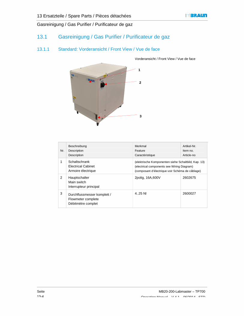
13 Ersatzteile / Spare Parts / Pièces détachées
Gasreinigung / Gas Purifier / Purificateur de gaz
Seite
13-4
MB20-200-Labmaster – TP700
Operating Manual – V 4.1 – 06/2014 - STD
13.1 Gasreinigung / Gas Purifier / Purificateur de gaz
13.1.1 Standard: Vorderansicht / Front View / Vue de face
Vorderansicht / Front View / Vue de face
Nr.
Beschreibung
Description
Description
Merkmal
Feature
Caractéristique
Artikel-Nr.
Item no.
Article-no
1 Schaltschrank Electrical Cabinet Armoire électrique
(elektrische Komponenten siehe Schaltbild, Kap. 13)
(electrical components see Wiring Diagram)
(composant d’électrique voir Schéma de câblage)
2 Hauptschalter Main switch Interrupteur principal
2polig, 16A,600V 2602675
3 Durchflussmesser komplett / Flowmeter complete Débitmètre complet
4..25 Nl 2600027
1
2
3

13 Ersatzteile / Spare Parts / Pièces détachées
MB20-200-Labmaster – TP700
Operating Manual – V 4.1– 06/2014 - STD
Seite
13-5
13.1.2 Rückansicht / Rear side / Vue arrière
Rückansicht / Rear side / Vue intérieure, à l'arrière
Nr.
Beschreibung
Description
Description
Merkmal
Feature
Caractéristique
Artikel-Nr.
Item no.
Article-no
1 a Ventil-Set Valve set Kit de vannes
(Spule, Kern, Feder)
(Core, spool, spring)
(bobine, noyau, ressort)
2600793
1 b Ventil-Block Valve Block- Distributeur
6-fach / 6 valves / 6 voies 4600978 *)
10-fach / 10 valves /10 voies 4600979 **)
2 Kühler Heat Exchanger Echangeurthermique
komplett / complete / complet 7016893 ***)
3 Gebläse Blower Turbine
MB-BL-01 9002832
4 a Reaktor Gasreinigung, komplett Reactor Gas purification, complete Réacteur de purification de gaz, complet
H2O / O2, 230 V 9002043-KF
H2O / O2, 115 V 9002044-KF
4 b Kupferkatalysator Cu-Catalyst Catalyseur cuivre
4.5kg 2600839
4 c Molekularsieb Molecular sieve Tamis moléculaire
5.5 kg 3240262
*) SP Version **) DP Version ***) option
1a) + 1b)
2
3
4(a,b,c)

13 Ersatzteile / Spare Parts / Pièces détachées
Gasreinigung / Gas Purifier / Purificateur de gaz
Seite
13-6
MB20-200-Labmaster – TP700
Operating Manual – V 4.1 – 06/2014 - STD
Forts. Rückansicht / Rear side / Vue intérieure, à l'arrière
Nr.
Beschreibung
Description
Description
Merkmal
Feature
Caratéristique
Artikel-Nr.
Item no.
Article-no
1 Wellschlauch Flexline Tuyau annelé
DN40KFx350 3203000
2 „ DN40KFx500 3200072
3 „ DN40KFx250 3240545
4 Haupterdungsanschluss Main grounding connection Raccord de terre principal
10mm² / 5meter 2603712
-- Erdungssatz für Groundig-Set for Kit de mise à la terre pour
UNILAB 2603711
-- „ Labmaster 2603710
1
2
3
4

13 Ersatzteile / Spare Parts / Pièces détachées
MB20-200-Labmaster – TP700
Operating Manual – V 4.1– 06/2014 - STD
Seite
13-7
13.1.3 Option: Boxspülen / Box Purging / Purge de la boite
Rückansicht / Rear side
Pos
Beschreibung
Description
Description
Merkmal
Feature
Caractéristique
Artikel-Nr.
Item no.
Article-no
1 Kugelhahn 2-Wege 2-way ball valve Robinet à boisseau
3/8" V2A 3240521
„ 3/8’’ MS 5017016
2 Magnetventil Magnetic Valve Set Électrovanne
VSE 4600977
3 Eckventil HV Angle Valve Vanne à angle droit
MB-EPV-40 (Al)
9002531-K
„ vernickelt, NI-plated, nickelée 9002533-K
4 PVC-Schlauch (Spülen Ausgang) PVC-Hose (Purging Outlet) Tuyau en PVC (sortie de purge)
800mm 2602195
a) Schlauchklemme Hose clamp Collier pour tuyaux souples
32-50mm 2501116
b) Al-Rohr 42x1 L=100mm Al-Tube Tube en Alu
42x1 L=100mm 2300221
5 Rückschlagventil komplett (Ausgangventil) Non-return valve (Purging out) Clapet anti-retour (vanne de sortie)
DN40 komplett 7024588
1
2
3
4
5
a)
b)
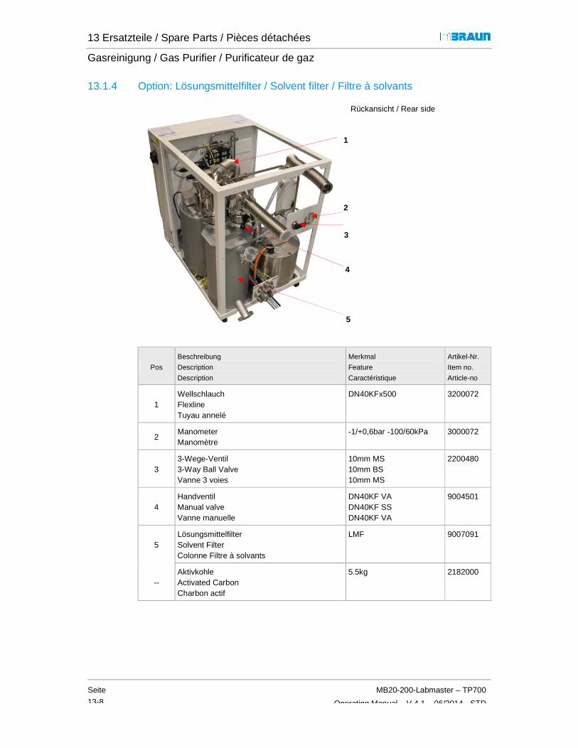
13 Ersatzteile / Spare Parts / Pièces détachées
Gasreinigung / Gas Purifier / Purificateur de gaz
Seite
13-8
MB20-200-Labmaster – TP700
Operating Manual – V 4.1 – 06/2014 - STD
13.1.4 Option: Lösungsmittelfilter / Solvent filter / Filtre à solvants
Rückansicht / Rear side
Pos
Beschreibung
Description
Description
Merkmal
Feature
Caractéristique
Artikel-Nr.
Item no.
Article-no
1 Wellschlauch Flexline Tuyau annelé
DN40KFx500 3200072
2 Manometer Manomètre
-1/+0,6bar -100/60kPa 3000072
3 3-Wege-Ventil 3-Way Ball Valve Vanne 3 voies
10mm MS 10mm BS 10mm MS
2200480
4 Handventil Manual valve Vanne manuelle
DN40KF VA DN40KF SS DN40KF VA
9004501
5 Lösungsmittelfilter Solvent Filter Colonne Filtre à solvants
LMF 9007091
-- Aktivkohle Activated Carbon Charbon actif
5.5kg 2182000
1
2
3
4
5

13 Ersatzteile / Spare Parts / Pièces détachées
MB20-200-Labmaster – TP700
Operating Manual – V 4.1– 06/2014 - STD
Seite
13-9
13.1.4.1 Option: Regenerierbarer LMF / Regenerable solvent filter / Filtre à solvants régénérable
Rückansicht / Rear side
Pos
Beschreibung
Description
Description
Merkmal
Feature
Caractéristique
Artikel-Nr.
Item no.
Article-no
1 Druckregler Pressure controller Régulateur de pression
1/8‘‘ 4601276
2 Durchflussmesser komplett Flowmeter complete Débitmètre complet
mit Rückschlagventil with non- return-valve avec clapet anti-retour
2600027
-- Reaktor regenerierbar Reactor regenerabble Réacteur régénérable
H2O/ O2 - 230V 13A für / for / pour reg. LMF
7038320
-- Molekularsieb Molecular sieve Tamis moléculaire
13x 1/8 APG 3240262
1
2

13 Ersatzteile / Spare Parts / Pièces détachées
Gasreinigung / Gas Purifier / Purificateur de gaz
Seite
13-10
MB20-200-Labmaster – TP700
Operating Manual – V 4.1 – 06/2014 - STD
13.1.5 Option: ECO Mode / Eco Mode /
Rückansicht / Rear side
Pos
Beschreibung
Description
Description
Merkmal
Feature
Caractéristique
Artikel-Nr.
Item no.
Article-no
1 PVC-Schlauch (Spülen Ausgang) PVC-Hose (Purging Outlet) Tuyau en PVC (sortie de purge)
800mm 2602195
2 Schlauchklemme Hose clamp Collier pour tuyaux souples
32-50mm 2501116
3 Eckventil HV Angle Valve Vanne à angle droit
MB-EPV-40 (Al)
9002531-K
„ vernickelt, NI-plated,
nickelée 9002533-K
3a Rückschlagventil komplett (Ausgangventil) Non-return valve (Purging out) Clapet anti-retour (vannede sortie)
DN40 komplett 7024588
4 Wie 3 / same as 3 / -- --
1
2
3 3a)
4

13 Ersatzteile / Spare Parts / Pièces détachées
MB20-200-Labmaster – TP700
Operating Manual – V 4.1– 06/2014 - STD
Seite
13-11
13.2 Inertgas-Box / Inertgas Box / Boîte à gants
13.2.1 Gehäuse MOD (Pro) und Beleuchtung / Chassis and light / Châssis et éclairage (Pro)
Pos
Beschreibung
Description
Description
Merkmal
Feature
Caractéristique
Artikel-Nr.
Item no.
Article-no
1 Beleuchtung komplett Lightening complete Éclairage complet
L1 - 1200/1250/1500 7070758
L 2 - 1800/2000 7075061
2 Leuchtstofflampe - Tageslicht weiß Fluorescent lamp - cool white Tube fluorescent - lumière du jour blanche
L1 - 30W 2603476
L2 - 58W 2603916
3 Scheibe Polycarbonat *) Window polycarbonate Vitre en polycarbonate
MOD-1250 MOD-1500 MOD-1800
7002195 7002448 7002443
*) Weitere Artikel bei MBRAUN erfragen
For further articles ask MBRAUN Autres articles disponibles auprès de MBRAUN
1
2
3

13 Ersatzteile / Spare Parts / Pièces détachées
Inertgas-Box / Inertgas Box / Boîte à gants
Seite
13-12
MB20-200-Labmaster – TP700
Operating Manual – V 4.1 – 06/2014 - STD
13.2.2 Gehäuse (Plus) und Beleuchtung / Chassis and light / Châssis et éclairage (Plus)
Pos
Beschreibung
Description
Description
Merkmal
Feature
Caractéristique
Artikel-Nr.
Item no.
Article-no
1 Beleuchtung komplett lighting complete éclairage complet
L1 7070758
L2 / L3
7075061
2 Leuchtstofflampe Fluorescent lamp Lampe fluorescente
L1 30W 2603476
L2 / L3 58W
2603916
3 Scheibe Polycarbonat Window polycarbonate Vitre en polycarbonate
L1 7002688
L2 --
L3 7011242
Länge der Box
Length of the box
Longueur de la boîte [mm]
L1 1200 L3 2000 --
1, 2
3

13 Ersatzteile / Spare Parts / Pièces détachées
MB20-200-Labmaster – TP700
Operating Manual – V 4.1– 06/2014 - STD
Seite
13-13
13.2.3 Partikelfilter / Particle Filter / Filtre à particules
Pos
Beschreibung
Description
Description
Merkmal
Feature
Caractéristique
Artikel-Nr.
Item no.
Article-no
1 Partikelfilter Particlefilter Filtre à particules
MB-BF-L-03 (H13)
9004513
1

13 Ersatzteile / Spare Parts / Pièces détachées
Inertgas-Box / Inertgas Box / Boîte à gants
Seite
13-14
MB20-200-Labmaster – TP700
Operating Manual – V 4.1 – 06/2014 - STD
13.2.4 Handschuhe + Zubehör / Gloves and Accessoires / Gants et accessoires
13.2.4.1 Handschuhe / Gloves / Gants
Pos
Beschreibung
Description
Description
Ø
[mm]
Material
Material
Matériau
Stärke
Strength
Epaisseur [mm]
Größe
Size
Taille
Merkmal
Feature
Caractér.
Artikel-Nr.
Item no.
Article-no
1 Handschuhe Gloves Gants
220
Brom-Butyl
0,4 1) Large A 3000047
0,4 Large Y 3240567
0,4 Medium A 3000018
0,8 Large Y 3240568
0,8 Large A 3000048
Hypalon 0,4 Medium A 3005010
0,4 Large Y 3005009
160 Brom-Butyl
0,4 Large Y 3000051
0,4 Large A 3000050
Oval 0,4 Large Y 3005008
Legende Legend Légende
1) Standard Y beidhändig / ambidextrous / ambidextre A anatomisch / anatomical / anatomique
Handschuhe ohne Talkum : Artikel-Nr. wie oben und – OT (z.B. 3000047-OT)
Gloves without talcum powder : Article No. as above shown and – OT (z.B. 3000047-OT)
Gants sans talc: Numéro d’article ci-dessus et –OT (p.ex. 3000047-OT)
1

13 Ersatzteile / Spare Parts / Pièces détachées
MB20-200-Labmaster – TP700
Operating Manual – V 4.1– 06/2014 - STD
Seite
13-15
13.2.4.2 Handschuh-Durchführung / Glove Feedthrough / Rond de gant
Detail
Pos
Beschreibung
Description
Description
Ø
[mm]
Merkmal
Feature
Caractéristique
Artikel-Nr.
Item no.
Article-no
1 Handschuhdurchführung kpl. Gloveport feedthrough cpl. Rond de gant cpl.
220 mit. O-Ringen with O-Rings avec joint toriques
7070842
160 9004667
2 O-Ringe für O-rings for Joint torique
innere Handschuhdurchführung inner gloveport feedthrough Rond de gant intérieur
220 250x4 2400138
3 O-Ringe für O-rings for Joint torique
äußere Handschuhdurchführung outer gloveport feedthrough Rond de gant extérieure
239x7 2603048
4 O-Ringe für O-rings for Joint torique
Befestigung Handschuhe fixation of gloves Fixation de gant
180x6 2600239
160 140x6 2600240
Weitere Handschuhtypen und O-Ringe können über die MBRAUN -Serviceabteilung bestellt werden
Other types of gloves and O-rings can be ordered through the MBRAUN Service Department.
D'autres types de gants et joints toriques peuvent être commandés auprès du Service Maintenance MBRAUN .
3 4 1 2
Zwischenraum Scheibe Interspace window Espace de la vitre

13 Ersatzteile / Spare Parts / Pièces détachées
Inertgas-Box / Inertgas Box / Boîte à gants
Seite
13-16
MB20-200-Labmaster – TP700
Operating Manual – V 4.1 – 06/2014 - STD
13.2.4.3 Verschlussdeckel / Port cover / Couvercle
Pos
Beschreibung
description
description
Ø
[mm]
Merkmal
feature
entité
Artikel-Nr.
item no.
article-no
1 Innenverschlussdeckel Inner glove port cover Couvercle intérieur pour rond de gant
160 7024831
220 9002371
2 Außenverschlußdeckel Outer glove port cover Couvercle extérieur pour rond de gant
160 7024791
220 7019882
1 2

13 Ersatzteile / Spare Parts / Pièces détachées
MB20-200-Labmaster – TP700
Operating Manual – V 4.1– 06/2014 - STD
Seite
13-17
13.2.5 Messgeräte / Sensors / Capteurs de mesure
MB-OX-SE1
MB-MO-SE1
MB-OX-EC
Pos
Beschreibung
Description
Description
Merkmal
Feature
Caractéristique
Artikel-Nr.
item no.
article-no
1 O2 Sensor O2 Sensor Capteur O2
0 – 1000 ppm O2 1500686
1a blaues Anschlußkabel 10m blue Connection cable 10m
Blue RJ45 2604966-S
2 H2O Sensor H2O Sensor Capteur H2O
0 – 500 ppm H2O 1500685
2a Grünes Anschlußkabel 10m green Connection cable 10m
Green RJ45 2604967-S
3 O2 Sensor O2 Sensor Capteur O2
0 – 1000 ppm O2 1500716
3a blaues Anschlußkabel 10m blue Connection cable 10m
Blue RJ45 2604966-S
4 Boxdruck-Sensor Box pressure sensor Capteur de pression de la boîte
+/- 20mbar 4970009
4a) Sensor-Kabel, geschirmt Actor cable, shielded Câble de raccordement, blindé
M12, 4-polig, 5 m 5008018
3
1 2
a) 4

13 Ersatzteile / Spare Parts / Pièces détachées
Schleusen / Antechambers / Sas
Seite
13-18
13.3 Schleusen / Antechamber
13.3.1 Hauptschleuse / Main Antechamber
Pos
Beschreibung
Description
Description
1 Manometer Manometer Manomètre
2 Schaltkreuz Antechamber door handlePoignée de porte
3 Minischleuse Mini antechamber Mini sas
Details Schleusendeckel -
Details Antechamber cover
Détails de la porte du sas
Schleusentür – linke Seite
2
satzteile / Spare Parts / Pièces détachées
Schleusen / Antechambers / Sas
MB20-200-Labmaster
Operating Manual – V 4.1 –
/ Antechambers / Sas
Hauptschleuse / Main Antechamber / Sas principal 390 mm
Merkmal
Feature
Caractéristique
G1/4 - VA - 1/0 bar.-100/0 kPa
Antechamber door handle innen + außen inner + outer en dedans + extérieure
siehe / see / voir
13.3.2
- siehe nächst Seite
Details Antechamber cover - see following page
sas - voir page suivante
3
1
linke Seite
2
Schleusentür – rechte Seite
Labmaster – TP700
– 06/2014 - STD
390 mm
Artikel-Nr.
Item no.
Article-no
2405004
en dedans + extérieure
7040131

13 Ersatzteile / Spare Parts / Pièces détachées
MB20-200-Labmaster – TP700
Operating Manual – V 4.1– 06/2014 - STD
Seite
13-19
Pos
Beschreibung /
Description
Description
Merkmal
Feature
Caractéristique
Artikel-Nr.
Item no.
Article-no
1 Gewindebuchse / Door shock spacer Douille filetée
7003702
2 Gasdruckfeder 120mm Hub / Gaspiston for antechamber / Amortisseur à gaz
350N 300N (standard)
2179000
3240327
3 Schleusenbalken Türhalter Door arm complete Barre de sas support de porte
rechts / right / côté droit
6000034
„ links / left /
côté gauche 6000035
4 Schleusendeckel / Antechamber door Porte de sas
7003674
5 Schleusendeckel komplett *) Antechamber door cover, complete *) Porte de sas complète *)
Rechts / right côté droit
9005225
*) mit Schleusendeckel, - balken + Gasdruckfeder *) with antechamber door, - door arm, Doors hock spacer *) avec Porte de sas , Barre de sas, Amortisseur à gaz
links left côté gauche
9005226
6 O-Ring für Schleusendeckel O-ring for Antechamber Door Joint torique pour porte de sas
Innen und außen Inner and outer intérieur et extérieur)
2400309
1
2
3
4
5 6

13 Ersatzteile / Spare Parts / Pièces détachées
Schleusen / Antechambers / Sas
Seite
13-20
MB20-200-Labmaster – TP700
Operating Manual – V 4.1 – 06/2014 - STD
13.3.1.1 Hauptschleuse Handventile / Main antechamber hand valves / Sas principal vanne manuelle
Rückseite / Rear side / à l'arrière
Pos
Beschreibung
Description
Description
Merkmal
Feature
Caractéristique
Artikel-Nr.
Item no.
Article-no
1 Handventil (DN40 VA)
Butterfly valve 9004501
2 2-Wege Kugelhahn 3/8’
2-way ball valve 3/8’
3240521
3
Vakuumschlauch
Vacuum hose
Tuyau à vide
l = 660mm, flexibel
7038898
4 Einschraub-Verschraubung
Screwed insert 10mm x 3/8‘ ISOA konisch
2210047
2
3
1
4

13 Ersatzteile / Spare Parts / Pièces détachées
MB20-200-Labmaster – TP700
Operating Manual – V 4.1– 06/2014 - STD
Seite
13-21
13.3.1.2 Schleusenautomatik zeitgesteuert/ Automatic AC time-controlled / Sas automatique du temps
Rückseite / Rear side / à l'arrière
Pos
Beschreibung
Description
Description
Merkmal
Feature
Caractéristique
Artikel-Nr.
Item no.
Article-no
1 Magnetventil Magnetic valve Électrovanne
2/2-Wege / ways / à voies 0-8 bar
4600977
2 Eckventil Angel Valve Vanne à angle droit
MB-EPV-40 (Al)
9002531-K
Eckventil Angel Valve Vanne à angle droit
MB-EPV-40 vernickelt / Ni-plated / nickelé
9002533-K
3 Ventilbuchsenstecker mit Kabel 7-pol. EPV40, l = 4m 5006151
4 Ventilsteckverbinder 2-pol, LED, l = 4,6m 5006097
2
1
3
4

13 Ersatzteile / Spare Parts / Pièces détachées
Schleusen / Antechambers / Sas
Seite
13-22
13.3.1.3 Schleusenautomatik / Automatic AC / Sas automatique
Pos
Beschreibung
Description
Description
1 Pirani Messröhre Vacuum pirani sensor Jauge de mesure Pirani
2 T-Stück T-Piece Raccord en T
„
3 Atmosphären-DrucksensorAtmospheric pressure sensor Capteur de pression atmosphérique
3 a Anschlusskabel Connection cable Câble de raccordement
4 Magnetventil Magnetic valve Électrovanne
5 Eckventil Angel Valve Vanne à angle droit
5 Eckventil Angel Valve Vanne à angle droit
Ersatzteile / Spare Parts / Pièces détachées
Schleusen / Antechambers / Sas
MB20-200-Labmaster
Operating Manual – V 4.1 –
Schleusenautomatik / Automatic AC / Sas automatique
Rückseite / Rear side / à l'arrière
Merkmal
Feature
Caractéristique
Vacuum pirani sensor
de mesure Pirani 0..1000 mbar
DN16 ISO-KF Alu / Alloy / inox
DN16 ISO-KF Edelstahl / Stainless steel /inox
Drucksensor Atmospheric pressure sensor Capteur de pression atmosphérique
-1000..636 mbar, 1..10V
Câble de raccordement
M12, 5 m
2/2-Wege / ways / à voies0-8 bar
Vanne à angle droit
MB-EPV-40 (Al)
Vanne à angle droit
MB-EPV-40 vernickelt / Ni-plated / nickelé
2
3
3 a
1
5 4
Labmaster – TP700
– 06/2014 - STD
à l'arrière
Artikel-Nr.
Item no.
Article-no
3226006
3201024
Edelstahl / Stainless steel 3201050
1..10V 4970007
5008018
/ ways / à voies 4600977
9002531-K
9002533-K
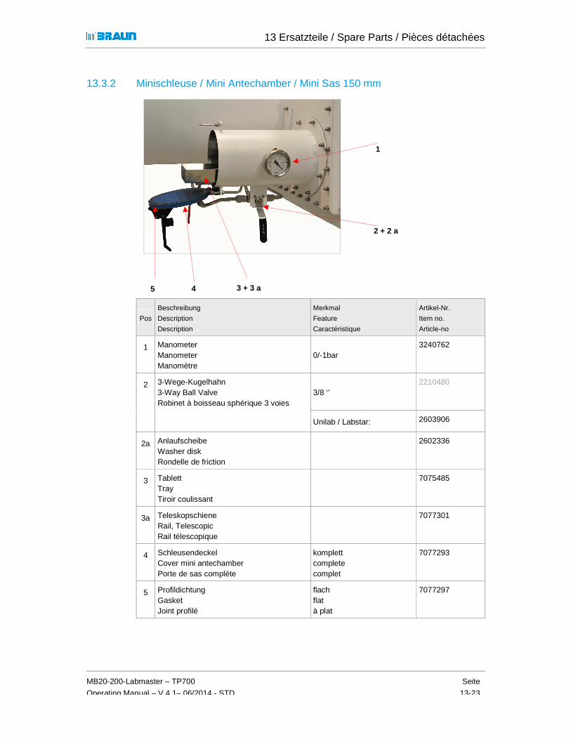
13 Ersatzteile / Spare Parts / Pièces détachées
MB20-200-Labmaster – TP700
Operating Manual – V 4.1– 06/2014 - STD
Seite
13-23
13.3.2 Minischleuse / Mini Antechamber / Mini Sas 150 mm
Pos
Beschreibung
Description
Description
Merkmal
Feature
Caractéristique
Artikel-Nr.
Item no.
Article-no
1 Manometer Manometer Manomètre
0/-1bar 3240762
2 3-Wege-Kugelhahn 3-Way Ball Valve Robinet à boisseau sphérique 3 voies
3/8 ‘’ 2210480
Unilab / Labstar: 2603906
2a Anlaufscheibe Washer disk Rondelle de friction
2602336
3 Tablett Tray Tiroir coulissant
7075485
3a Teleskopschiene Rail, Telescopic Rail télescopique
7077301
4 Schleusendeckel Cover mini antechamber Porte de sas complète
komplett complete complet
7077293
5 Profildichtung Gasket Joint profilé
flach flat à plat
7077297
1
5 4
2 + 2 a
3 + 3 a

13 Ersatzteile / Spare Parts / Pièces détachées
Vakuum-Pumpe / Vacuum Pump / Pompe à vide
Seite
13-24
MB20-200-Labmaster – TP700
Operating Manual – V 4.1 – 06/2014 - STD
13.4 Vakuum-Pumpe / Vacuum Pump / Pompe à vide
13.4.1 Standard
Pos
Beschreibung
Description
Description
Merkmal
Feature
Caractéristique
Artikel-Nr.
Item no.
Article-no
1 Vakuumpumpe Vacuum Pump Pompe à vide
RV12 3240487
2 Gasballast-Ölrückführung Gas ballast oil return Gaz ballast et retour d’huile
RV3-RV12 3240540
3 Ölfilter Oil Mist Filter Filtre à brouillard d'huile
EMF20 3240539
13.4.2 Upgrade: Tri-Scroll-Vakuum-Pumpe / Vacuum pump / Pompe à vide
Pos
Beschreibung
Description
Description
Merkmal
Feature
Caractéristique
Artikel-Nr.
Item no.
Article-no
1 Vakuumpumpe Vacuum Pump Pompe à vide
TriScroll PTS 310,1 1-phasig / single phase / monophasée
2193001
„ 3-phasig / three phases / triphasé 2193000
1
2
3
Option: Spülkit / Purge Kit / Kit de purge s. 13.4.2.1
1

13 Ersatzteile / Spare Parts / Pièces détachées
MB20-200-Labmaster – TP700
Operating Manual – V 4.1– 06/2014 - STD
Seite
13-25
13.4.2.1 Tri-Scroll-Pumpe / pump / pompe: Spülkit / Purge kit / Kit de purge
Beispiel / Example
Pos
Beschreibung
Description
Description
Merkmal
Feature
Caractéristique
Artikel-Nr.
Item no.
Article-no
1 Manometer Manometer Manomètre
0..1 bar 4601278
2 Druckregler Pressure controller Régulateur de pression
1/8"; 0,1-0,7 bar entlüftend / de-airing / désaération
4601276
3 Magnetventil Magnetic Valve Électrovanne
A-02,4 3210017
4 Spülkit (Durchflußmesser + Anbauteile) Purge kit Kit de purge
für TriScroll-Pumpe for TriScroll Pump pour pompe TriScroll
3000053
3
1 + 2
4

13 Ersatzteile / Spare Parts / Pièces détachées
Steuerung / Controlling / Commande
Seite
13-26
13.5 Steuerung / Controlling /
13.5.1 Bedienpanel / Operation Panel /
Pos
Beschreibung
description
description
1 Bedienpanel Touch Panel Ecran tactile
2 Gehäuse für BedienpanelCabinet for Touch panel Boîtier de panneau de commande
3 SchlauchverschraubungStraight grommet Raccord à vis pour tuyau
4 KabelschutzschlauchGray wire track Gaine de protection des
5 Panelhalter MetallbügelMetal bracket Support du panneau
6 Panelhalter – KunststoffPlastic OP bracket Pièce intermédiaire
6 5
Ersatzteile / Spare Parts / Pièces détachées
Steuerung / Controlling / Commande
MB20-200-Labmaster
Operating Manual – V 4.1 –
Steuerung / Controlling / Commande
Bedienpanel / Operation Panel / Écran tactile
Merkmal
feature
entité
a) TP700 (Labmaster, MB20-200)
b) TFT70 (Unilab, Labstar)
Gehäuse für Bedienpanel Cabinet for Touch panel
anneau de commande
Rechts / Links Right/Left) à droite/à gauche
Schlauchverschraubung
Raccord à vis pour tuyau
Kabelschutzschlauch
Gaine de protection des câbles
Panelhalter Metallbügel
Support du panneau
Kunststoff
Pièce intermédiaire
3
4
1 b
Labmaster – TP700
– 06/2014 - STD
Artikel-Nr.
item no.
article-no
200) 2605141
7107449
7023898
2600272
5003044
7070745
7070761
1 a

13 Ersatzteile / Spare Parts / Pièces détachées
MB20-200-Labmaster – TP700
Operating Manual – V 4.1– 06/2014 - STD
Seite
13-27
13.5.2 Fußschalter / Foot Switch / Pédalier
Pos
Beschreibung
Description
Description
Merkmal
Feature
Caractéristique
Artikel-Nr.
Item no.
Article-no
1 Fußschalter Foot switch Pédalier
5007021
1

13 Ersatzteile / Spare Parts / Pièces détachées
Option : Kühlschrank / Refrigerator / Congélateur
Seite
13-28
13.6 Option : Kühlschrank / Refrigerator / Congélateur
Pos
Beschreibung
description
description
1 Kompressor Compressor Compresseur
Nur für Nachrüstungen /
Temperaturregler Temperature controllerRégulateur de temperature
Ersatzteile / Spare Parts / Pièces détachées
Option : Kühlschrank / Refrigerator / Congélateur
MB20-200-Labmaster
Operating Manual – V 4.1 –
: Kühlschrank / Refrigerator / Congélateur
innen / inside / intérieur:
Merkmal
feature
entité
MB GS-35 - 230V 50Hz
ür Nachrüstungen / Only for Upgrade Kits
Temperature controller Régulateur de temperature
Kit Beta Elektronik
Freistehende Einheit Stand-Alone-Unit Stand-Alone-Systeme
1
Labmaster – TP700
– 06/2014 - STD
Artikel-Nr.
item no.
article-no
2600996
2600530

14 Third Party Documentation
MB20-200-Labmaster – TP700
Operating Manual – V 4.1– 06/2014 - STD
Page
14-1
14.1 Overview ............................................................................................... 14-2

14 Third Party Documentation
Overview
Page
14-2
MB20-200-Labmaster – TP700
Operating Manual – V 4.1– 06/2014 - STD
14 Third Party Documentation
14.1 Overview
No. Hersteller Art.Nr. MBraun
Beschreibung Typ Sprache PDF1)
1 BOC Edwards
3240487 Rotary Vane Pump RV3/5/8/12
A652-01-882
English x
2 3240539 Oil Mist Filters EMF3, EMF10, EMF 20 A462-26-880
English x
3 3240540 EMF Adjustable Gas Ballast Oil Drain Kit for RV3 to RV12 Pumps
A505-23-882 English x
4 ------- Vacuum Leadthroughs and Accessories
Model 6EK25, 7EK10, 10EK25, TL8K25, Earth Electrical Leadthrough,
Model 4RK 10, 8RK25, 12RK25 Rotary Shaft Vacuum Seal
6EK25, 10EK25 Extension Accessory, Type 10, 25 Blanking Plug E-100-99-880
English x
5 Jumo 4970009 Pressure Sensor 24VDC +/- 20 mbar
Multilingual x
6 MBRAUN SEW Eurodrive
2700636 Parameter Settings for Frequency Inverter
LTE-B 200-240V
English x
1) PDF files see CD-ROM or USB-Stick (Annex)

15 Certificates
MB20-200-Labmaster – TP700
Operating Manual – V 4.1 - 06/2014 - STD
Page
15-1
15.1 Overview .......................................... ..................................................... 15-2

15 Certificates
Overview
Page
15-2
MB20-200-Labmaster – TP700
Operating Manual – V 4.1 – 06/2014 - STD
15 Certificates
15.1 Overview
N° Manufacturer Description Type Language
1 MBRAUN CE-Declaration UNIlab Pro/Plus sp/dp English
2
3

16 Electrical system & wiring diagrams
MB20-200-Labmaster – TP700
Operating Manual – V 4.1 – 06/2014 - STD
Page
16-1
16.1 Safety when handling the electrics of the system ............................. 16-2 16.1.1 Basic rules ............................................................................................................ 16-2 16.1.2 Control cabinet ..................................................................................................... 16-3 16.1.3 Work on the electrical system .............................................................................. 16-3 16.1.4 Electrical safety check .......................................................................................... 16-3
16.2 Wiring Diagrams ................................................................................... 16-4

16 Electrical system & wiring diagrams
Safety when handling the electrics of the system
Page
16-2
MB20-200-Labmaster – TP700
Operating Manual – V 4.1 – 06/2014 - STD
16 Electrical system & wiring diagrams
16.1 Safety when handling the electrics of the system
DANGER!
Risk of personal injury due to electrical voltage in case of error: uncontrolled muscle reactions, crippling, burns or death can result!
► All work on the mains connection, the control cabinet and the electrical system may only be performed by a trained electrician.
In case of electrical shock, inform the emergency physician immediately
Emergency OFF
If components are integrated into the MBRAUN system and equipped with an EMERGENCY OFF switch, please follow the note below:
DANGER
Personal injury and environmental damage due to incorrect operation!
An EMERGENCY OFF of third-party components switches off only these components!
► In case of danger, switch off the main switch on the system's control cabinet!
16.1.1 Basic rules
� The system must be grounded at all times. If necessary, additional potential equalisation must be provided (see chap. Installation and wiring diagrams)
� The mains connection must be made according to local guidelines.
� Modifications to the electrical system must be made in agreement with MBRAUN
� Modifications to the electrical system must always be documented in the wiring diagram
16 Electrical system & wiring diagrams
MB20-200-Labmaster – TP700
Operating Manual – V 4.1 – 06/2014 - STD
Page
16-3
16.1.2 Control cabinet
DANGER
Risk of personal injuries due to electrical voltage in case of error:
� The system may not be operated with an open control cabinet door!
► Only a trained electrician may open the control cabinet.
Before opening the control cabinet and starting work on the electrical system
► Switch off the main switch
► Or: remove the mains plug from the outlet or de-energise the mains connection!
► Secure it against being switched on again.
16.1.3 Work on the electrical system
Before working on the electrical system:
► Measure potential
The system must be de-energized!
16.1.4 Electrical safety check
After each change to the electrical systems / maintenance and repair, perform an electrical test.
Cyclical testing is due according to BGV A3 / national operational safety regulations or in-house regulations.
► Document the inspection performed in the MBRAUN maintenance log
► Compare the measured values with the data from the Initial test to evaluate the test result.

16 Electrical system & wiring diagrams
Wiring Diagrams
Page
16-4
MB20-200-Labmaster – TP700
Operating Manual – V 4.1 – 06/2014 - STD
16.2 Wiring Diagrams
Included on CD supplied with system
Contact MBRAUN Service for assistance


M. Braun Inc. 14 Marin Way Stratham, NH 03885
Tel.: +1 (603) 773-9333 • Fax: +1 (603) 773-0008 E-Mail: [email protected] • Internet: www.mbraun.com