glow-worm - compact 100p - lets fix it€¦ · · 2017-04-13register your glow-worm appliance ......
TRANSCRIPT

221680G.11.00
Hepworth Heating Ltd.,Nottingham Road, Belper, Derbyshire. DE56 1JT
General/Sales enquiries:Tel: (01773) 824141 Fax: (01773) 820569One Contact Local Service
Customer Services:
Tel: (01773) 828100
Fax: (01773) 828070
Instructions for UseInstallation and Servicing
To b e l e f t w i t h t h e u s e r
This is a Cat I2H
Appliance
6936
Fanned Flue Combination BoilerWith Honeywell gas control
G.C. No. 47 047 05A
COMPACT 100p
All replacement parts
All labour charges
All call-out charges
Guarantee Registration
REGISTER YOUR GLOW-WORM APPLIANCEFOR 1ST YEAR GUARANTEE PROTECTION
CALL 0208 247 9857
Thank you for installing a new Glow-worm appliance in your home.
Glow-worm appliances' are manufactured to the very highest standard so we are pleasedto offer our customers' a Comprehensive First Year Guarantee.
In the centre pages are to be found your Guarantee Registration Card, which we recommend you complete andreturn as soon as possible.
If this card is missing you can obtain a copy or record your registration by telephoning the Heatcall CustomerService number 01773 828100.
Our Guarantee gives you peace of mind plus valuable protection against breakdown by covering the cost of:
The instructions consist of three parts, User, Installation and Servicing Instructions, which include the Guarantee Registration Card.
The instructions are an integral part of the appliance and must, to comply with the current issue of the Gas Safety (Installation and Use)
Regulations, be handed to the user on completion of the installation.

2221680G
Testing and Certification
This boiler is tested and certificated for safety and performance. It is therefore important that no alteration is made to the boiler,without permission, in writing, from Hepworth Heating Ltd.
Any alteration not approved by Hepworth Heating Ltd., could invalidate the certification, boiler warranty and may also infringe thecurrent issue of the Statutory Requirements, see Section 1.4.
CE Mark
This boiler meets the requirements of Statutory Instrument No. 3083 The boiler (Efficiency) Regulations, and therefore isdeemed to meet the requirements of Directive 92/42/EEC on the efficiency requirements for new hot water boilers fired withliquid or gaseous fuels.
Type test for purposes of Regulation 5 certified by: Notified body 0086.
Product/production certified by: Notified body 0086.
The CE mark on this appliance shows compliance with:
1. Directive 90/396/EEC on the approximation of the laws of the Member States relating to appliances burninggaseous fuels.
2. Directive 73/23/EEC on the harmonization of the Laws of the Member States relating to the electrical equipmentdesigned for use within certain voltage limits.
3. Directive 89/336/EEC on the approximation of the Laws of the Member States relating to electromagneticcompatibility.
Substances Hazardous to Health
The adhesives and sealants used in this appliance are cured and give no known hazard in this state.
INSULATION PADS/CERAMIC FIBRE, GLASSYARN, MINERAL WOOLThese can cause irritation to skin, eyes and the respiratory tract.If you have a history of skin complaint you may be susceptible to irritation. High dust levels are usual only if the material isbroken.Normal handling should not cause discomfort, but follow normal good hygiene and wash your hands before eating, drinking orgoing to the lavatory.
If you do suffer irritation to the eyes or severe irritation to the skin seek medical attention.
Important Information
Introduction 3Clock Settings 4Lighting the Boiler 5
General Data 1 7Boiler Location 2 9Flue and Ventilation 3 10Heating System 4 11Domestic Hot Water System 5 12Installation Preparation andGas/Water Connections 6 13Flue Preparation 7 14Mounting the Boiler and Flue Fitting 8 16Electrical Connections 9 18Commissioning 10 20
General Data 11 23Servicing 12 23Fault Finding 13 24Replacement Parts 14 32Spare Parts 15 43
CONTENTS DESCRIPTION SECTION PAGE No.
INSTRUCTIONS
FOR USE
INSTALLATION
INSTRUCTIONS
SERVICING
INSTRUCTIONS

3 221680G
0
I121314
15
1617
1819
20
21
2223 24 1
2
3
45
67
8
910
11AUTO RUN
M T W Th F S Su
P
DAY HR MINP
R
I
Introduction
Please read these instructions and follow them carefully for thesafe and economical use of your Combination boiler.
This boiler must have been installed by a competent person inaccordance with the current rules in force in the countries ofdestination at the time of installation.
Once the controls are set, the boiler is automatic in operation.
The Compact combination boiler is able to provide room heatingas part of a central heating system and domestic hot waterdirect from the cold water supply, without the need for secondarystorage.
The boiler can be fitted with one of two makes of clock, whichlook like this:-
IMPORTANT NOTICE:
This boiler is for use only on G20 gas.
Gas Leak or Fault
If a gas leak or fault exists or is suspected, turn the boiler off andconsult your local gas company or your local installation/servicing company.
Domestic Hot Water Temperature
NOTE. The mains incoming water temperature in the winter islower than in the summer.
The water temperature is factory preset and can not beadjusted.
To achieve the same outlet water temperature in the winter, itwill be necessary to reduce the water flow rate using the hotwater tap.
Boilers Installed in Compartments
If the boiler has been fitted into a compartment or cupboard, donot obstruct the compartment air supply vents.
Do not use the compartment for storage.
Electrical Supply
WARNING. The boiler must be earthed.
The boiler must be connected to a 230V~50Hz permanentsupply.
Connection of the whole electrical system of the boiler and anyheating system controls to the electrical supply, must be throughone common isolator.
Isolation should preferably be by a double pole switched fusedspur box. The fused spur box should be readily accessible andpreferably adjacent to the appliance. It should be identified asto its use.
Alternatively a fused 3A 3 pin plug and shuttered unswitchedsocket may be used.
The colours of three core flexible cable are, blue - neutral, brown- live, green and yellow - earth.
As the markings on your plug may not correspond with thesecolours continue as follows:-
The wire coloured blue must be connected to the terminalmarked “N” or “Black”.
The wire coloured brown must be connected to the terminalmarked “L” or “Red”.
The wire coloured green and yellow must be connected to theterminal marked “E” or “Green” or the earth symbol .
PVC flexible cable having a conductor size of 0.75mm2 (24/0.20mm) must be used within the boiler casing to connect to theboiler.
Electrical Supply Failure
The boiler will not work without an electrical supply.
Normal operation of the boiler should resume when the electricalsupply is restored.
If the power is off, except for short controled periods, turn off thepilot.
Note. The boiler safety cutoff may have operated, please referto the following section to reset.
Reset any external controls, to resume normal operation of thecentral heating.
The digital timer, has a lithium battery back up and will not needresetting. Unless it is without power for a considerable period.
Boiler Safety Cut-off Device
The boiler is fitted with a safety cutoff device to prevent damagethrough overheating.
Should the main burner and pilot go out, for no apparentreason, during normal use, allow the boiler and system tocool down (waiting at least a minimum of four minutes),relight the boiler as described in "To light the boiler".
If the problem persists, turn the boiler off and consult yourinstallation/ servicing company.
The Gas Safety (Installation & Use)Regulations
In your interests and that of safety it is the law that ALL gasappliances are installed by competant persons in accordancewith the current issues of the above regulations.
6937Clock / Timers
Digital timer Electro / mechanicalclock / timer
Instructions for Use
4221680G
0
I121314
15
1617
1819
20
21
2223 24 1
2
3
45
67
8
910
11 Setting Timed Programmes
With the clock set to the correct time, see SETTING THECLOCK paragraphs 1-4, and then continue as follows:
1. Set RUN switch to P , the display will indicatethe 1st (ON) preset programme and the symbol .
2. Set day of week to be programmed by pressing theDAY button.
Note: The days can be selected individually or asgroups:
Mon-Fri., Mon-Sat., Mon-Sun., Sat/Sun.
An arrow will be displayed under the dayor days selected.
3. Set time of day by pressing the buttons HR and MIN.
4. Press button P to confirm programmes, thedisplay will indicate the 2nd (OFF) preset programmeand subsequently, 3rd, 4th, 5th, 6th, 7th, 8th.
5. Repeat procedures 2, 3 and 4 until desiredprogrammes are set.
Note. It is not a requirement to use the 8 on/offprogrammes.
6. Set the RUN switch the central position, yourappliance will now operate at the programmed times.
General Notes.
With the AUTO switch in the I position the centralheating will operated constantly ON.
With the AUTO switch in the O position the centralheating will not operate.
Soft Override button indicated by thesymbol , this function will override the currentcentral heating programme for the next available.
ON time programmes are indicated by the symbol .
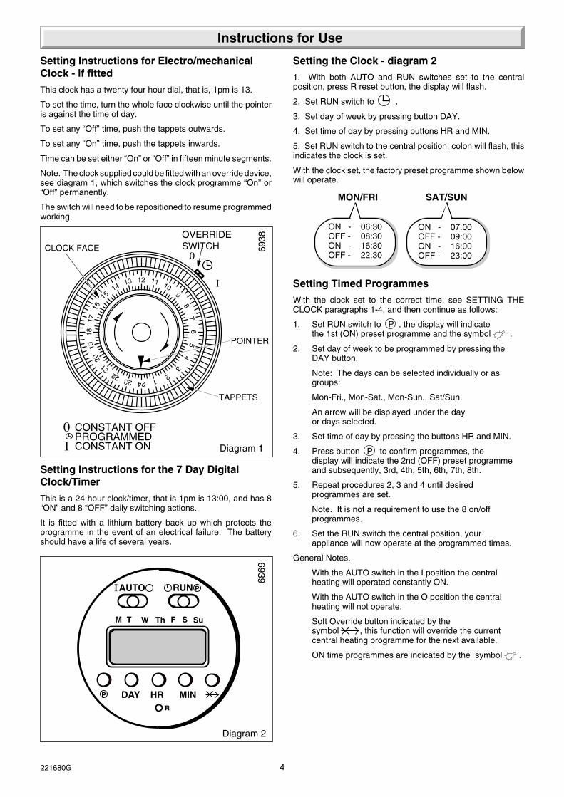
Setting the Clock - diagram 2
1. With both AUTO and RUN switches set to the centralposition, press R reset button, the display will flash.
2. Set RUN switch to .
3. Set day of week by pressing button DAY.
4. Set time of day by pressing buttons HR and MIN.
5. Set RUN switch to the central position, colon will flash, thisindicates the clock is set.
With the clock set, the factory preset programme shown belowwill operate.
Setting Instructions for Electro/mechanicalClock - if fitted
This clock has a twenty four hour dial, that is, 1pm is 13.
To set the time, turn the whole face clockwise until the pointeris against the time of day.
To set any “Off” time, push the tappets outwards.
To set any “On” time, push the tappets inwards.
Time can be set either “On” or “Off” in fifteen minute segments.
Note. The clock supplied could be fitted with an override device,see diagram 1, which switches the clock programme “On” or“Off” permanently.
The switch will need to be repositioned to resume programmedworking.
Diagram 1
OVERRIDESWITCH
POINTER
TAPPETS
CLOCK FACE
CONSTANT OFFPROGRAMMEDCONSTANT ON
0
I
6938
Setting Instructions for the 7 Day DigitalClock/Timer
This is a 24 hour clock/timer, that is 1pm is 13:00, and has 8“ON” and 8 “OFF” daily switching actions.
It is fitted with a lithium battery back up which protects theprogramme in the event of an electrical failure. The batteryshould have a life of several years.
Instructions for Use
Diagram 2
6939
MON/FRI
ON - 06:30OFF - 08:30ON - 16:30OFF - 22:30
SAT/SUN
ON - 07:00OFF - 09:00ON - 16:00OFF - 23:00
AUTO RUN
M T W Th F S Su
P
DAY HR MINP
R
I

5 221680G
To Light the Boiler1. Check that all four isolating valves are open, the levers in linewith the valve body, see diagram 3.
2. Open the controls cover door and familiarize yourself with thecontrols, see diagram 4.
3. CAUTION. A sealed pressurised system must be filled andpressurised by a competent person.
Only operate the boiler when you are sure that the system hasbeen filled and pressurised. Check this by looking at thepressure gauge “A”, it should read 0.7bar minimum.
4. Open a hot water tap, check that water flows, then close it.
5. If you are in any doubt about the boiler being filled with watercontact your installation/servicing company or the local gascompany.
6. Fully press and hold down the control knob “C”. Press andrelease the piezo button “D” until the pilot burner lights, viewthrough window in the front case. When the pilot burner is lit,keep control knob “C” pushed in for a further 15 seconds thenrelease. The pilot should remain alight.
7. IF THE PILOT GOES OUT NOW, OR ON ANY OTHEROCCASION, A SAFETY DEVICE PREVENTS IMMEDIATERELIGHTING. WAIT AT LEAST FOUR MINUTES BEFOREATTEMPTING TO RELIGHT.
8. If the pilot burner fails to remain alight, repeat instruction 11.but now hold down the control knob “C” for a little longer after thepilot has lit.
9. Check the pilot is alight and stable.
10. Switch ON the electrical supply to the boiler at the externalisolator.
11. Set the switch “K” to ON 1 situated on the control fascia.
Instructions for Use
12. Check the light “E” is illuminated on the control fascia.
13. Set the summer / winter button “J”, light “H” or “F” willilluminate.
14. Set “B”, clock/timer (if fitted) and any remote controls asrequired.
For central heating operation set button “J” to “On” . The mainburner will ignite. Light “F” will illuminate.
Close the controls cover door.
To Turn the Boiler OffFor short periods only set switch “K” to 0 . Turn off pilot light.
To turn the boiler off, turn the control knob “C” in the directionof the arrow clockwise.
To turn on again following the "To light the boiler" instructions.
Water TemperaturesNOTE. The mains incoming water temperature in the winter islower than in the summer.
To achieve the same outlet water temperature in the winter, itwill be necessary to reduce the water flow rate using the hotwater tap.
Summer / Winter Selector ButtonFor central heating set button “J” to Winter light “F” will illuminate.The main burner will light.
When the heating is controlled by a room thermostat and/or atime switch, button “J” must be set to Winter light “F” willilluminate.
If a hot water tap is opened while the boiler is on for heating,priority will be given to hot water.
Maintenance and ServicingTo ensure the continued efficient and safe operation of theappliance it is recommended that it is checked and serviced asnecessary at regular intervals. The frequency of servicing willdepend upon the particular installation conditions and usage,but in general once a year should be enough.
If this appliance is installed in a rented property there is a dutyof care imposed on the owner of the property by the currentissue of the Gas Safety (Installation and Use) Regulations,Section 35.
Servicing/maintenance should be carried out by a competentperson in accordance with the rules in force in the countries ofdestination.
To obtain service, please call your installer or Heatcall (Glow-worm’s own service organisation) using the telephone numberbehind the controls cover door.
Please be advised that the ‘Benchmark’ logbook should becompleted by the installation engineer on completion ofcommissioning and servicing.
All CORGI Registered Installers carry a CORGI ID card, andhave a registration number. Both should be recorded in yourboiler Logbook. You can check your installer is CORGI registeredby calling CORGI direct on :- 01256 372300.
ClearancesThe boiler requires a clearance in front, below and at the sidesof the casing for safety, servicing and maintenance access, seediagram 2.1.
Protection Against FreezingIf the boiler is to be out of use for any long periods during severeweather, it is recommended that the whole system, includingthe combination boiler, should be drained to avoid the risk offreezing.
If in doubt, contact you installation/servicing company for advice.
Diagram 3
GASSERVICECOCK
HOTWATEROUT
COLDWATERSUPPLY IN
HEATINGFLOW
HEATINGRETURN
LEVER (OPEN)COLD WATERSUPPLY IN/OUT
SLOT (OPEN)GAS SERVICECOCK
LEVER (OPEN)HEATINGFLOW/ RETURN
7310
SAFETY VALVEDISCHARGE PIPE POSITION

6221680G
Instructions for Use
Draining and Filling
CAUTION. This boiler works in a pressurised system whichmust only be drained, refilled and pressurised by a competentperson.
Note: If the pressure gauge indicates a loss of system pressure,that is, less than 0.7bar, YOU MUST CONTACT YOURINSTALLER.
Pressure Relief Safety Valve
CAUTION. A pressure relief safety valve and discharge pipe isfitted to the boiler. This valve must not be touched. Should therebe any discharge from the pipe, turn the boiler off, isolate fromthe electrical supply and contact your installation/servicingcompany. The outlet should be kept clear
Cleaning
WARNING. This appliance contains metal parts (components)and care should be taken when handling and cleaning withparticular regard to edges.
The boiler casing can be cleaned using a mild liquid detergentwith a damp cloth, then a dry cloth to polish.
Do not use any form of abrasive or solvent cleaner as you maydamage the paint work
Boiler Casing
CAUTION. Do not remove or adjust the casing in any way, asincorrect fitting may result in incorrect operation or failure tooperate at all. If in doubt seek advice from the local gascompany or your installation/servicing company.
Replacement Parts
If replacement parts are required apply to your local supplier orBritish Gas.
Please quote the name of the appliance.
7565
7004
MAINSELECTRIC
SWITCH ‘K’
CONTROL
KNOB ‘C’
SUMMER/ WINTER
BUTTON ‘J’PRESSUREGAUGE ‘A’
Diagram 4
‘H’
‘G’
‘E’ ‘F’
PIEZO ‘D’
CONTROLS COVER
CONTROLSFASCIA
CLOCK TIMER
IF FITTED ‘B’
KEY TO NEON LIGHTS
‘G’ LOW WATER PRESSURE
‘H’ SUMMER SETTING (HOT WATER OPERATION ONLY)
‘F’ WINTER SETTING (HOT WATER AND CENTRAL HEATING OPERATION)
‘E’ POWER ‘ON’

7 221680G
CL
H
9mm
JL
K K
22mm COMPRESSIONCENTRAL HEATING
15mm COMPRESSIONDOMESTIC WATER
Rc 1/2 (1/2in. BSPT)GAS CONNECTION
CL
F
C
D
E
N B
AG
M
FLUE
A B C D E F G H J K L M N
450 700 300 100 75 128 225 18 135 65 110 80 144
1 General Data7029
1.1 Installation
Materials and equipment should be fit for their purpose and ofsuitable quality and workmanship.
1.2 Important Notice
This boiler is for use only on natural gas, G20.
1.3 Sheet Metal Parts
WARNING. When installing or servicing this boiler care shouldbe taken when handling the edges of sheet metal parts to avoidany possibility of personal injury.
1.4 Requirements
The installation of this boiler must be carried out by a competentperson in accordance with the current rules in force in thecountries of destination at the time of installation.
Manufacturer’s instructions, supplied.
Manufacturer’s instructions must not be taken as overridingstatutory requirements.
1.5 Data Label
The data label is on the inner case cover, see diagram 1.2.
1.6 Data
See table 1 and diagrams 1.1, 1.2 & 1.3.
The Seasonal Efficiency Domestic Boilers UK (SEDBUK) is71.6%.
The value is used in the UK Government’s Standard AssessmentProcedure (SAP) for energy rating of dwellings. The test datafrom which it has been calculated have been certified by B.S.I.
Diagram 1.1
Lift Weight 33.4kg (73.63b)
Total Weight 42.8kg (94.36lb)
Gas connection Ø 15mm compression
Heating and return Ø 22mm compression
Domestic hot water Ø 15mm compression
Safety valve Preset 3bar (43.5lbf/in2)
Safety valve discharge Ø 15mm copper
Water content 1.66 litres (0.37 gallon)
Expansion vessel capacity 6 litres (1.32 gallons)
Heating cold fill 0.7barpressure minimum (10.1lbf/in2)
D.H.W 0.8 to 10barworking pressure
Maximum Heating 60 litressystem water (13.2 gallons)content using with a coldfitted expansion fill pressurevessel. of 0.7bar
Electrical supply 230V~50Hz
Electrical rating 154W fused 3A
Internal Fuse rating F1) Type T2AF2) Type T315mA
For larger systems use an additional expansionvessel, see Section 4.
Boiler starts at an inlet pressure of 0.5bar butrequires 0.8bar for maximum output.
TABLE 1

8221680G
1.7 Gas Supply
The gas installation shall be in accordance with the rules inforce in the countries of destination.
The supply from the governed meter must be of adequate sizeto provide a steady inlet working pressure of 20mbar (8in wg) atthe boiler.
1.8 Electrical Supply
WARNING. This boiler must be earthed.
All system components shall be of an approved type.
The electrical installation shall be in accordance with thecurrent rules in force in the countries of destination at the timeof installation.
Connection of the whole electrical system of the boiler and anyheating system controls to the electrical supply, must be throughone common isolator.
Isolation should be by a double pole switched fused spur box,having a minimum contact separation of 3mm in each pole.The fused spur box should be readily accessible and preferablyadjacent to the appliance.It should be identified as to its use.
Alternatively, a fused 3A 3pin plug and unswitched socket maybe used, provided they are not used in a room containing a bathor shower.
The mains supply cable and other cables connected to theboiler must be the PVC flexible type of at least 0.75mm2 (24/0.20mm) .
1 General Data
HEPWORTH HEATING LTD.,BELPER,DERBYS. DE56 1JT
COMPACT 100P 457401
SERIAL
HEATING CIRCUIT PMS = 2.5 barDOMESTIC CIRCUIT PMW = 10 barSPECIFIC WATER RATE 14.03 l/min.
No.
GC No. 47-047-05A
008686/AU/582
GB IE
230V 50Hz 150W Fused at 3AFor use on : -G20 - 20 mbar
G20
This boiler is intended exclusivelyto be installed on a gas supplywith a governed meter
MIN DHW MAX. CH MAX.
HEAT INPUT NETT kWkWHEAT OUTPUT
10.9319.9317.6
32.2HOT BURNER PRESSURE mbar 0.624.513.6
29.3 8.79
INJECTOR: 4.7mm 205765
2H
TYPE : C - C
Q =P =
NO Class 5x3212
7505
Diagram 1.2
1.9 Heating System Controls
The heating system should have installed: a timer and roomthermostat controlling the boiler.
Thermostatic radiator valves may be installed, however theymust not be fitted in a room where the room thermostat islocated.
Note: All systems must have at least one radiator not fitted witha thermostatic valve.
Note: For further information, see The Building Regulations1991 - Conservation of fuel and power, 1995 edition - AppendixG, table 4b.
7643
Diagram 1.3
FANNEDFLUE AUTOMATIC
AIR VENT
PILOTBURNER
EXPANSIONVESSEL
MAIN BURNER
HEAT EXCHANGER
PUMP
LOW WATERPRESSURESWITCH
GAS VALVE
SAFETYVALVE
SAFETYVALVE
DISCHARGE
OVERHEATCUT-OFF
TEMP.SENSOR
OVERHEATCUT-OFF
TEMP.SENSOR
BYPASSVALVE
D.H.W.COLDINLET
D.H.W.HOTOUTLETC.H.
FLOWC.H.
RETURN
FLOWSENSOR
GAS

9 221680G
25 ABOVE THE TOP OFTHE FLUE ELBOW
55450
150
To achieve minimum "Installation" clearance of 5mm.The side panels will have to be fitted priorto boiler mounting.
6944
DIMENSIONS IN MILLIMETRES Diagram 2.1
2.1 Location
This boiler must be installed in accordance with the rules inforce in the countries of destination.
This boiler is not suitable for outdoor installation.
Any electrical switch must be positioned so that it cannot betouched by a person using the bath or shower.
The boiler must be mounted on a flat wall which is sufficientlyrobust to take its weight, refer to Table 1, “Data”.
If the location of the boiler or any part of the system is subjectto severe cold weather conditions, it is recommended that afrost thermostat is fitted. Any part of the system that may bevulnerable to freezing must be protected.
2.2 Boilers in a Compartment
Where the installation of the boiler will be in an unusual position,the current issue of BS6798 gives detailed guidance on theserequirements.
An existing cupboard or compartment modified for the purposemay be used, providing minimum clearances are maintained.Details of essential requirements for cupboard or compartmentdesign are given in the current issue of BS6798.
The door way opening should be of sufficient size to allow foreasy removal of the boiler.
Where the boiler is fitted in a cupboard or compartment,permanent ventillation is not required.
Any existing compartment air vents must not be removed orblocked off.
2.3 Clearances
The boiler should be positioned so that at least the minimumoperational and servicing clearances are provided, see diagram2.1. Additional clearances may be required around the boiler forinstallation.
2.4 Timber Frame Buildings
If the boiler is to be installed in a timber frame building it shouldbe fitted in accordance with the Institute of Gas Engineersdocument IGE/UP/7/1998. If in doubt seek advice from the localgas undertaking or Hepworth Heating Ltd.
2 Boiler Location
10221680G
A
A
FG E
A
G
G
G
B,C B,C
F FK
K
K
C
G
L L
UNDER CAR PORT etc.
H,I
JD
FK
MINIMUMSPACING
2816
Diagram 3.1
3 Flue and Ventilation
3.1 General
The flue must be installed in accordance with the rules in forcein the countries of destination.
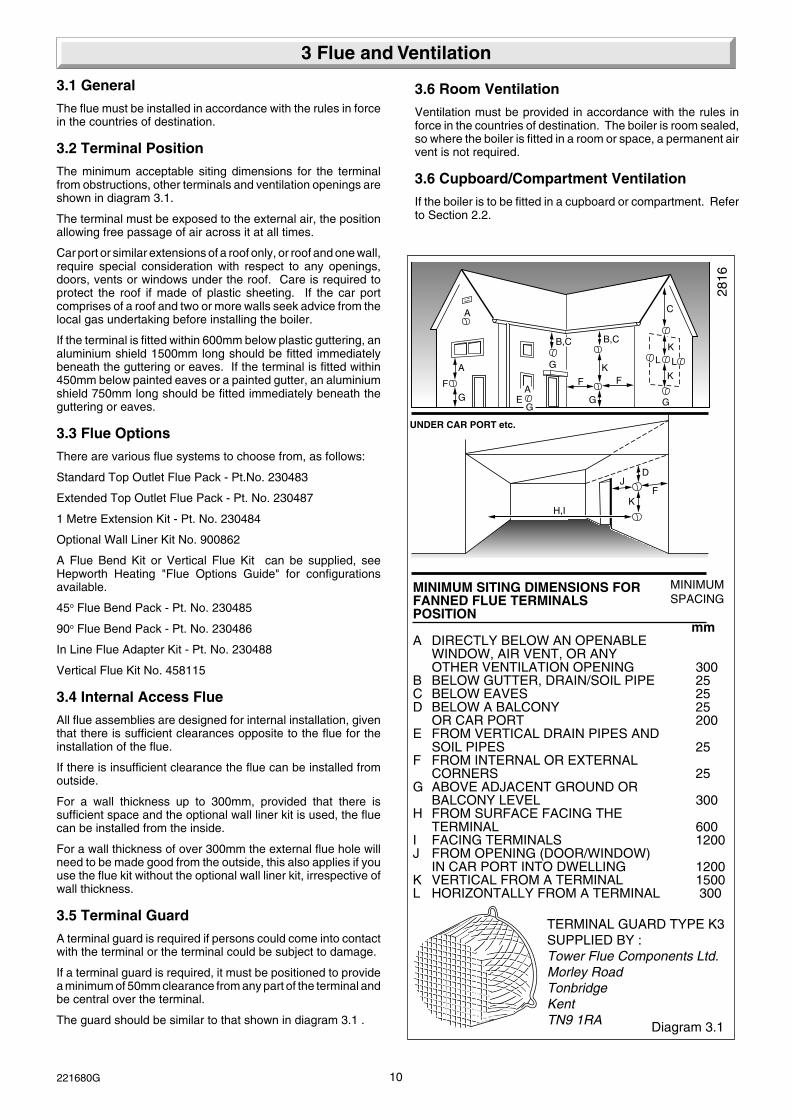
3.2 Terminal Position
The minimum acceptable siting dimensions for the terminalfrom obstructions, other terminals and ventilation openings areshown in diagram 3.1.
The terminal must be exposed to the external air, the positionallowing free passage of air across it at all times.
Car port or similar extensions of a roof only, or roof and one wall,require special consideration with respect to any openings,doors, vents or windows under the roof. Care is required toprotect the roof if made of plastic sheeting. If the car portcomprises of a roof and two or more walls seek advice from thelocal gas undertaking before installing the boiler.
If the terminal is fitted within 600mm below plastic guttering, analuminium shield 1500mm long should be fitted immediatelybeneath the guttering or eaves. If the terminal is fitted within450mm below painted eaves or a painted gutter, an aluminiumshield 750mm long should be fitted immediately beneath theguttering or eaves.
3.3 Flue Options
There are various flue systems to choose from, as follows:
Standard Top Outlet Flue Pack - Pt.No. 230483
Extended Top Outlet Flue Pack - Pt. No. 230487
1 Metre Extension Kit - Pt. No. 230484
Optional Wall Liner Kit No. 900862
A Flue Bend Kit or Vertical Flue Kit can be supplied, seeHepworth Heating "Flue Options Guide" for configurationsavailable.
45o Flue Bend Pack - Pt. No. 230485
90o Flue Bend Pack - Pt. No. 230486
In Line Flue Adapter Kit - Pt. No. 230488
Vertical Flue Kit No. 458115
3.4 Internal Access Flue
All flue assemblies are designed for internal installation, giventhat there is sufficient clearances opposite to the flue for theinstallation of the flue.
If there is insufficient clearance the flue can be installed fromoutside.
For a wall thickness up to 300mm, provided that there issufficient space and the optional wall liner kit is used, the fluecan be installed from the inside.
For a wall thickness of over 300mm the external flue hole willneed to be made good from the outside, this also applies if youuse the flue kit without the optional wall liner kit, irrespective ofwall thickness.
3.5 Terminal Guard
A terminal guard is required if persons could come into contactwith the terminal or the terminal could be subject to damage.
If a terminal guard is required, it must be positioned to providea minimum of 50mm clearance from any part of the terminal andbe central over the terminal.
The guard should be similar to that shown in diagram 3.1 .
MINIMUM SITING DIMENSIONS FORFANNED FLUE TERMINALSPOSITION
mmA DIRECTLY BELOW AN OPENABLE
WINDOW, AIR VENT, OR ANYOTHER VENTILATION OPENING 300
B BELOW GUTTER, DRAIN/SOIL PIPE 25C BELOW EAVES 25D BELOW A BALCONY 25
OR CAR PORT 200E FROM VERTICAL DRAIN PIPES AND
SOIL PIPES 25F FROM INTERNAL OR EXTERNAL
CORNERS 25G ABOVE ADJACENT GROUND OR
BALCONY LEVEL 300H FROM SURFACE FACING THE
TERMINAL 600I FACING TERMINALS 1200J FROM OPENING (DOOR/WINDOW)
IN CAR PORT INTO DWELLING 1200K VERTICAL FROM A TERMINAL 1500L HORIZONTALLY FROM A TERMINAL 300
3.6 Room Ventilation
Ventilation must be provided in accordance with the rules inforce in the countries of destination. The boiler is room sealed,so where the boiler is fitted in a room or space, a permanent airvent is not required.
3.6 Cupboard/Compartment Ventilation
If the boiler is to be fitted in a cupboard or compartment. Referto Section 2.2.
TERMINAL GUARD TYPE K3SUPPLIED BY :Tower Flue Components Ltd.Morley RoadTonbridgeKentTN9 1RA

11 221680G
0.00
1.00
2.00
3.00
4.00
5.00
0 5 10 15 20 25Circuit flow rate (l/min)
Rem
aini
ng c
onve
ying
cap
acity
(m H
2O)
0
10
20
30
40
50
∆t (
°C)
Dt at 60000 btu outputDp (MH2O)
4.1 General Notes
The boiler is intended for use in a sealed system only.
4.2 Safety Valve
The safety valve is an integral part of the boiler.
It cannot be adjusted but has a manual test device.
4.3 Pressure Gauge
A pressure gauge is incorporated into the boiler to indicate thesystem pressure.
The gauge has a cold fill set pointer.
4.4 Pump
The circulation pump is integral with the boiler.
The remaining circulating pressure head available from theboiler is shown in diagram 4.1.
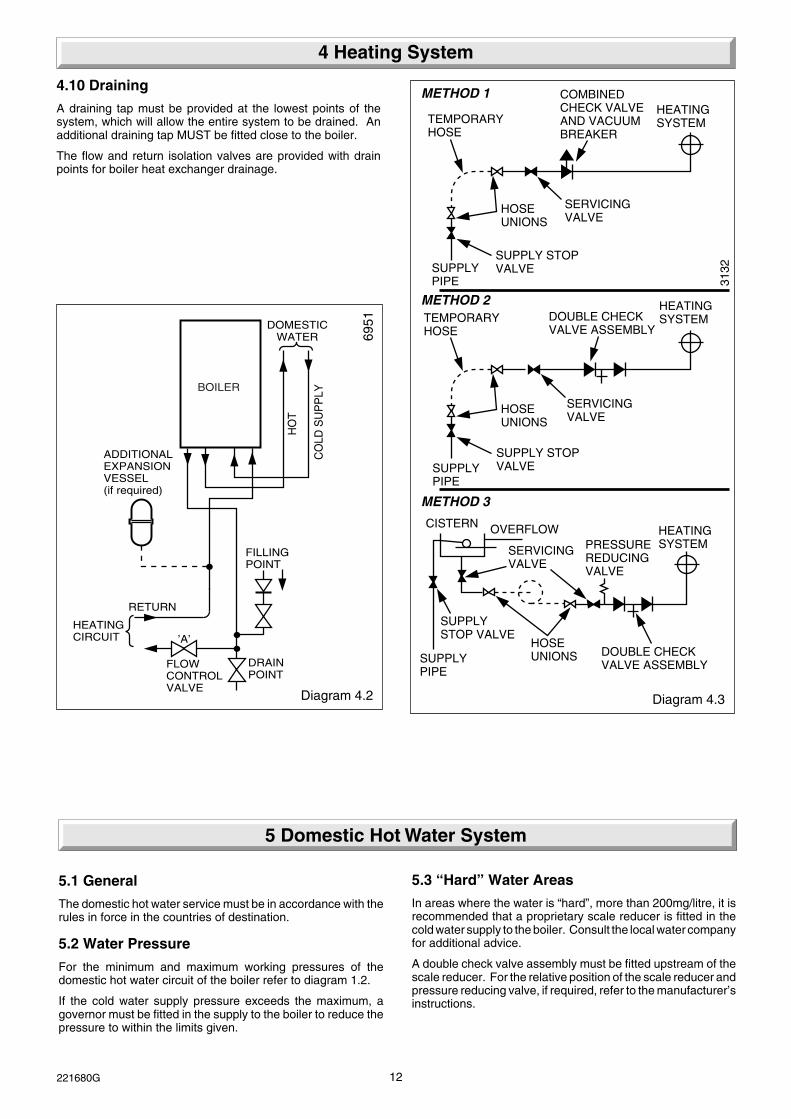
4.5 Expansion Vessel
The boiler has an integral expansion vessel with a capacity of6Litres, (1.32gall). If the system water content exceeds themaximum quoted in Table 1, Data, an additional vessel shouldbe connected into the system as close as possible to the centralheating return connection of the boiler, see diagram 4.2.
The pressure shall not be less than the static head at the pointof connection, that is, the height of the top point of the systemabove the expansion vessel.
4.6 Flow Rate
If required a valve can be incorporated in the main flow or returnof the system, valve “A” shown in the flow diagram 4.2. Thisvalve must be lockable and positioned so that inadvertentclosure or unauthorised interference is not possible.
Diagram 4.1
4 Heating System
4.7 Bypass
The bypass is an integral part of the boiler and cannot beadjusted.
No external system bypass is required.
4.8 Filling Sealed Systems
Provision for filling the system at a low level must be made.Three methods of filling are shown in diagram 4.3.
There must be no permanent connection to the mains watersupply, even through a non-return valve.
NOTE: It is important that fittings used for connection to potablewater comply with the water undertakers requirements.
4.9 Corrosion Inhibitor
If an inhibitor is to be used in the system, contact the inhibitormanufacturer so that they can recommend their most suitableproduct.
When fitting the boiler into an existing system, special careshould be taken to drain the entire system, including radiators,then thoroughly cleaning out before fitting the boiler whether ornot adding an inhibitor.
7487
12221680G
BOILER
DOMESTICWATER
HO
T
CO
LD S
UP
PLY
FILLINGPOINT
OPTIONAL FILLINGKIT AVAILABLENo. 457120
DRAINPOINT
’A’
FLOWCONTROLVALVE
HEATINGCIRCUIT
RETURN
ADDITIONALEXPANSIONVESSEL(if required)
Diagram 4.3
METHOD 1
METHOD 2
METHOD 3
SUPPLY STOPVALVESUPPLY
PIPE
HOSEUNIONS
SERVICINGVALVE
TEMPORARYHOSE
HEATINGSYSTEM
HEATINGSYSTEMTEMPORARY
HOSE
HOSEUNIONS
SERVICINGVALVE
SUPPLYPIPE
SUPPLY STOPVALVE
DOUBLE CHECKVALVE ASSEMBLY
HEATINGSYSTEMSERVICING
VALVE
SUPPLYSTOP VALVE
SUPPLYPIPE
HOSEUNIONS DOUBLE CHECK
VALVE ASSEMBLY
OVERFLOWCISTERN
COMBINEDCHECK VALVEAND VACUUMBREAKER
PRESSUREREDUCINGVALVE
3132
6951
Diagram 4.2
4 Heating System
5.1 General
The domestic hot water service must be in accordance with therules in force in the countries of destination.
5.2 Water Pressure
For the minimum and maximum working pressures of thedomestic hot water circuit of the boiler refer to diagram 1.2.
If the cold water supply pressure exceeds the maximum, agovernor must be fitted in the supply to the boiler to reduce thepressure to within the limits given.
5 Domestic Hot Water System
4.10 Draining
A draining tap must be provided at the lowest points of thesystem, which will allow the entire system to be drained. Anadditional draining tap MUST be fitted close to the boiler.
The flow and return isolation valves are provided with drainpoints for boiler heat exchanger drainage.
5.3 “Hard” Water Areas
In areas where the water is “hard”, more than 200mg/litre, it isrecommended that a proprietary scale reducer is fitted in thecold water supply to the boiler. Consult the local water companyfor additional advice.
A double check valve assembly must be fitted upstream of thescale reducer. For the relative position of the scale reducer andpressure reducing valve, if required, refer to the manufacturer’sinstructions.

13 221680G
7028
UNIONCONNECTION
DISCHARGEPIPE
SAFETYVALVEDISCHARGE
Diagram 6.2
SEALINGWASHER
REAR VIEWOF BOILER
The installation requires the following components :-
1. Plumbing jig Carton
2. Boiler Carton
3. Flue Pack
6.1. Plumbing Jig
Remove from the carton the wall template, then follow theinstructions given on the template.
Note: It is important that the wall hanging bracket and theservice cock bracket are fitted to a flat and true wall area forcorrect alignment with the boiler. Where this cannot be achievedit is acceptable to pack out the service cock bracket to obtain thecorrect alignment with the wall hanging bracket.
6.2 Gas Connection
Provision is made for the gas supply to be connected frombelow the boiler, see diagrams 1.1 and 6.1 for position.
Refer also to “Gas Supply”, Section 1.7.
Make the gas supply connection to the gas service cock. Whilemaking the connection, do not subject the gas service cock toheat as you may damage the seals. Purge the gas supply.
6.3 Water Connections
Provision is made for the domestic cold water inlet to beconnected from below or through an internal wall at the rear ofthe boiler, see diagram 1.1 and 6.1 for position.
Refer also to Section 5 “Domestic Hot Water System”.
Provision is made for the water connections to be connectedfrom below or from above, passing down either side of theboiler. Take care that any pipework connected from above willclear the expansion vessel. Refer to the wall template. Ifconnecting from above a piping kit 457160 is available and isrecommended. If necessary, temporarily fit the boiler.
Flush out the domestic water and heating system beforeconnecting the boiler.
Make the connections to the domestic hot water outlet and theheating system by means of the isolating valves, see diagram6.1.
While making the connections. Do not subject any of theisolating valves to heat as you may damage the seals.
Make sure that the drain screw heads on the isolating valves areaccessible.
6.4 Safety Valve Discharge
WARNING. It must not discharge above an entrance or windowor any type of public access area.
A short discharge pipe is supplied loose with the boiler, whichwhen fitted to the safety valve, will end below the boiler theposition is next to the heating return, see diagram 6.2. (THEDISCHARGE PIPE MUST BE FITTED BEFORE THE BOILERIS MOUNTED ON THE WALL).
This must be extended, using not less than 15mm od metalpipe, to discharge, in a visible position, outside the building,facing downwards, preferably over a drain. The pipe must havea continuous fall and be routed to a position so that anydischarge of water, possibly boiling, or steam cannot create anydanger to persons, damage to property or external electricalcomponents and wiring.
Note. To ease future servicing it is advisable to use a compressiontype fitting to extend the discharge pipe.
6 Installation Preparation and Gas / Water Connections
Diagram 6.1
6956
GASSERVICECOCK
HOTWATEROUT
COLDWATERSUPPLYIN
HEATINGFLOW
HEATINGRETURN
SLOT (OPEN)COLD WATERSUPPLY IN/OUT
SLOT (OPEN)GAS SERVICECOCK
SLOT (OPEN)HEATINGFLOW/ RETURN
SAFETY DISCHARGEPIPE ROUTING POSITION

14221680G
Diagram 7.1
7508
7 Flue Preparation
REAR FLUESIDE FLUE
15mm
VIEW ’B’
VIEW ’B’
15mm
STD./EXTD. TOP OUTLET FLUE PACK & 1 METRE EXTENSION KIT
SCREW & TAPE
SCREW & TAPE
SCREW & TAPE
SCREW & TAPE
3 x 1 metre extension kits may be joined together.
FLUE LENGTHMAX 840mm (extd.) MAX 570mm (std)
FLUE LENGTHMAX 840mm (extd.) MAX 570mm (std)
15mm
SCREW & TAPE
117mm
36mm
TOP OUTLET FLUE PACK
’X’
’X’ plus 132mm = FLUE LENGTH
SIDE FLUE ’X’ plus 132mm = FLUE LENGTH REAR FLUE ’Y’ plus 50mm = FLUE LENGTH
’Y’
’X’
’Y’ plus 50mm = FLUE LENGTH
’Y’
CL
CL
TOP STD.REARSIDE
TOP EXTD.REARSIDE
MINIMUMWALL
THICKNESS
MINIMUMFLUE
LENGTH
MAXIMUMFLUE
LENGTH
"Y"BOILER MOUNTING FACETO EXTERNAL WALL FACE
"X"BOILER CASING TO
EXTERNAL WALL FACE
MAXIMUM DISTANCE FROM
126212
519-
-438
7575
7575
126212
840840
789-
-708
570570
FLUEPACKS
NOTE :IF IT IS NECESSARY TO CUT THE DUCTSTO ACHIEVE THE "FLUE LENGTH" MAKE SURE THAT THE OVERLAPS ARE AS FOLLOWS :-THE OVERLAP FOR AIR DUCT = 25mmTHE OVERLAP FOR FLUE DUCT = 50mm
THE MAXIMUM LENGTHS CAN BE INCREASEDBY AN ADDITIONAL 3 METRES WITH THE USE OF THE 1 METRE EXTENSION KITS.NOTE :THIS APPLIES TO STANDARD KITS ONLY.
7506
7.1 Flue Position and Length
Determine flue application, length and terminal position beforestarting, refer to diagram 7.1.
Note: The Standard Top Outlet Flue Pack and the ExtendedTop Outlet Flue Pack contains a flue duct extension piececomplete with "O" rings, this should be discarded.
If you are using a Flue Bend or a Vertical Flue Kit, please followthe instructions supplied with the kit.
To make a neat finish to the flue outlet a flue collar kit, part No.443286, with instructions, is available, see diagram 7.2.
Note: If required an optional wall liner kit, part no. 900862, isavailable complete with instructions.
7.2 Flue Assembly
Extend the telescopic flue to the required length, making surethat the minimum overlap is no less than 25mm, and that the flueterminal projects 15mm minmum beyond wall face, see diagram7.1.
Carefully drill though air duct pilot hole and secure with selftapping screw provided in fittings pack, see diagram 7.1.
Seal the joint with the tape provided.
If the flue system requires the addition of flue extension kits,drill, seal and secure them with the self tapping screw and tapeprovided.

15 221680G
Note: Should any one of the flue sections require cutting toobtain desired flue system length, cut at the end opposite theexpanded end.
If the boiler is not to be fitted for some time cover the hole in thewall.
7.3 Internal Access Flue
If access to the outside wall is not practical, the flue system canbe installed from inside. Use of the optional wall liner kit isrequired.
7.4 Top Outlet Rear Flue Fixing
Fit the self adhesive foam seal provided in the flue pack aroundthe air duct at the position shown in diagram 7.1.
Make good around the flue outside after installation of the boiler.
Important: If the wall liner kit is used, the self adhesive foam sealincluded in the wall liner kit must be used in place of the onesupplied with the flue pack, see diagram 7.3 for position of selfadhesive seal.
7.5 Top Outlet Side Flue Fixing
Make good the area around the flue inside and outside afterinstallation of the boiler.
Important: If the wall liner kit is used, the self adhesive foam sealincluded in the wall liner kit must be used in place of the onesupplied with the flue pack, see diagram 7.3 for position of selfadhesive seal.
7.6 Flue Positioning
Push the flue assembly into and through the hole such that it iswithin the wall, and does not stick out into the room. Do not pushthe flue assembly too far into the hole as it has to be pulled backinto the boiler and secured.
7 Flue Preparation
Diagram 7.2
7148
OPTIONALFLUECOLLAR
Diagram 7.3
FOAM SEAL
FOAM SEAL
WALL THICKNESS-OVER 300mm
15mm
WALL THICKNESS-UP TO 300mm
Q-35mm
Q
Q
7331
WITH WALL LINER KIT ONLY
16221680G
Diagram 8.1
7232INNER CASE
FRONT
SECURINGSCREW (4)
Diagram 8.2
7234ELECTRICAL
CONNECTORSSECURINGSCREW (2)
REAR BRACKET
FLUECOLLECTOR
WHITE AIRPRESSURESWITCH TUBE
8 Mounting the boiler and Flue Fitting
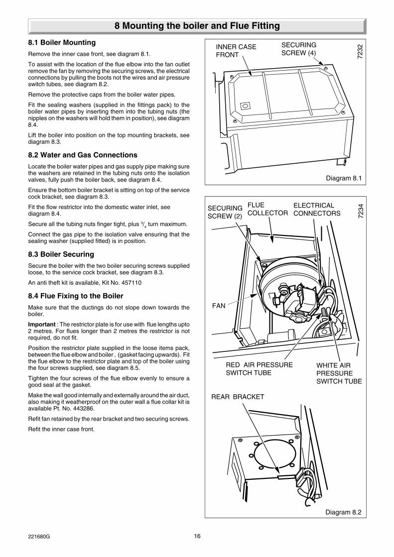
8.1 Boiler Mounting
Remove the inner case front, see diagram 8.1.
To assist with the location of the flue elbow into the fan outletremove the fan by removing the securing screws, the electricalconnections by pulling the boots not the wires and air pressureswitch tubes, see diagram 8.2.
Remove the protective caps from the boiler water pipes.
Fit the sealing washers (supplied in the fittings pack) to theboiler water pipes by inserting them into the tubing nuts (thenipples on the washers will hold them in position), see diagram8.4.
Lift the boiler into position on the top mounting brackets, seediagram 8.3.
8.2 Water and Gas Connections
Locate the boiler water pipes and gas supply pipe making surethe washers are retained in the tubing nuts onto the isolationvalves, fully push the boiler back, see diagram 8.4.
Ensure the bottom boiler bracket is sitting on top of the servicecock bracket, see diagram 8.3.
Fit the flow restrictor into the domestic water inlet, seediagram 8.4.
Secure all the tubing nuts finger tight, plus 3/4 turn maximum.
Connect the gas pipe to the isolation valve ensuring that thesealing washer (supplied fitted) is in position.
8.3 Boiler Securing
Secure the boiler with the two boiler securing screws suppliedloose, to the service cock bracket, see diagram 8.3.
An anti theft kit is available, Kit No. 457110
8.4 Flue Fixing to the Boiler
Make sure that the ductings do not slope down towards theboiler.
Important : The restrictor plate is for use with flue lengths upto2 metres. For flues longer than 2 metres the restrictor is notrequired, do not fit.
Position the restrictor plate supplied in the loose items pack,between the flue elbow and boiler , (gasket facing upwards). Fitthe flue elbow to the restrictor plate and top of the boiler usingthe four screws supplied, see diagram 8.5.
Tighten the four screws of the flue elbow evenly to ensure agood seal at the gasket.
Make the wall good internally and externally around the air duct,also making it weatherproof on the outer wall a flue collar kit isavailable Pt. No. 443286.
Refit fan retained by the rear bracket and two securing screws.
Refit the inner case front.
FAN
RED AIR PRESSURESWITCH TUBE

17 221680G
7075
TOP MOUNTINGBRACKET
BOILER
RETAINING LUG
Diagram 8.5
RESTRICTOR/GASKET
7233
FLUE ELBOW(REAR FLUESHOWN)
SECURINGSCREW (4)
PRODUCTSPROBE
8 Mounting the Boiler and Flue Fitting
Diagram 8.3SECURINGSCREW (2)
SERVICE COCKBRACKET
BOILERSECURING LUGNote: The lug mustbe positioned on topof the service cockbracket
8083
Diagram 8.4
BOILER WATER PIPES
SERVICECOCKS (4)
GAS SUPPLYPIPE
SEALINGWASHER (4)(INSERT INTOTUBING NUT)
FLOWRESTRICTOR(DOMESTIC WATER INLET)
TUBINGNUT

18221680G
R2
R1
N
L
9 Electrical Connections
Diagram 9.2
7024
CABLECLAMP
MAINSCABLE
SCREW (2)
BUSHCONNECTIONBLOCK
9.1 Supply Cable Connection
CAUTION: To prevent an induced current from switching thecentral heating on, when not required, it is important that theheating system control cables are separated from the othermains supply cables.
Open the controls cover door. Remove the two screws securingthe controls facia, see diagram 9.1.
Hinge the control fascia open.
The boiler requires a permanent mains supply through anexternal isolator which must also isolate any heating systemcontrols, see diagram 9.2.
Any heating system controls must not interrupt the permanentmains supply to the boiler.
Using PVC cable of a suitable length and rating as stated inSection 1.8 “Electrical Supply”, route the mains supply cableand connect to the appropriate terminals of the connector block,restrain with the cable clamp supplied, see diagram 9.2.
Standard colours are, Brown - Live, Blue - Neutral, Green andYellow - Earth.
Make the earth cable of a greater length so that if the cable isstrained the earth would be the last to become disconnected.
CAUTION: It is ESSENTIAL to make sure that the polarity iscorrect.
9.2 Heating System Controls
All external controls and wiring are required to provide aminimum of reinforced insulation at 250Vrms between the partsof those devices operating at mains hazardous voltage and theuser accessible parts af those devices.
The heating system should have installed: a programmer androom thermostat controlling the boiler.
Thermostatic radiator valves may be installed in addition to theroom thermostat.
Note: For further information, see The Building Regulations1991 - Conservation of fuel and power, 1995 edition - AppendixG, table 4b.
If electrical controls are not to be used to regulate the heatingsystem, do not remove the red link cable.
When any form of electrical control is being used to regulate theheating system, remove the red link cable and connect heatingsystem controls in series.
9.3 Clock/timer Kit (if applicable)
Fit the clock/timer kit following the appropriate sections of theinstructions supplied with it..
9.4 Frost Thermostat
If the installation requires protection by a “frost thermostat”,connect a single pole type, to the appropriate terminals of theconnector, see diagram 9.3.
Electrical Checks
Keep all cables away from hot surfaces.
Carry out preliminary electrical system checks as below:
1. Test insulation resistance to earth of mains cables.
2. Test earth continuity and short circuit of all cables
3. Test the polarity of the mains.
Refit the controls fascia.
REDLINK
Diagram 9.1
7189
CONTROLS COVER
SECURINGSCREW (2)CONTROLS
FASCIA

19 221680G
9 Electrical Connections
Diagram 9.3
7100
JUNCTIONBOX
3 AMPFUSE
L N
230V~50HzPERMANENT MAINSSUPPLY
230V~50HzROOM STAT.
230V~50HzFROST STAT.
TO BOILER
RED LINK.REMOVE WHENCONNECTINGSYSTEM CONTROLS
5 WAY TERMINAL BLOCK
230V~50HzPOTENTIAL
FROST STAT.
230V~50HzPOTENTIAL
ROOM STAT.
(L) (N) (R1) (R2)
JUNCTIONBOX
3 AMPFUSE
L N
230V~50HzPERMANENT MAINSSUPPLY
230V~50HzROOM STAT. USED AS LINK
230V~50HzFROST STAT.
TO BOILER
RED LINK.REMOVE WHENCONNECTINGSYSTEM CONTROLS
5 WAY TERMINAL BLOCK
MAINSPOTENTIAL
FROST STAT.
MAINSPOTENTIAL
ROOM STAT.
(L) (N) (R1) (R2)
JUNCTIONBOX
3 AMPFUSE
L N
230V~50HzPERMANENT MAINSSUPPLY
230V~50HzFROST STAT. NO ROOM STAT.
TO BOILER
REDLINK
5 WAY TERMINAL BLOCK
MAINSPOTENTIAL
FROST STAT.
(L) (N) (R1) (R2)
3 AMPFUSE
L N
230V~50HzPERMANENT MAINSSUPPLY
POTENTIALFREE ROOM STAT. NO FROST STAT.
TO BOILER
RED LINK.REMOVE WHENCONNECTINGSYSTEM CONTROLS
5 WAY TERMINAL BLOCK
POTENTIAL FREEROOM STAT.
(L) (N) (R1) (R2)
DOUBLEPOLE
ISOLATOR
JUNCTIONBOX
3 AMPFUSE
L N
230V~50HzPERMANENT MAINSSUPPLY
230V~50Hz ROOM STAT. NO FROST STAT.
TO BOILER
RED LINK.REMOVE WHENCONNECTINGSYSTEM CONTROLS
5 WAY TERMINAL BLOCK
MAINS POTENTIALROOM STAT.
(L) (N) (R1) (R2)
5 WAY TERMINAL BLOCK
TO BOILER
RED LINK.REMOVE WHENCONNECTING ANYHEATING SYSTEMCONTROLS
TIMECONTROL
CLOCK
SWITCHCONTACTS
(L) (N) (R1) (R2)
JUNCTIONBOX
3 AMPFUSE
ROOMTHERMOSTAT
FROSTTHERMOSTATL N E
230V~50HzPERMANENT
MAINS SUPPLY
ELECTRICITY SUPPLY CONNECTIONS
EXTERNAL CLOCK INTEGRAL CLOCK
INTEGRAL CLOCK
INTEGRAL CLOCK
INTEGRAL CLOCK
INTEGRAL CLOCK
DOUBLEPOLE
ISOLATOR
DOUBLEPOLE
ISOLATOR
DOUBLEPOLE
ISOLATOR
DOUBLEPOLE
ISOLATOR
DOUBLEPOLE
ISOLATOR
E
E
E
E
E

20221680G
7034
Diagram 10.1
BURNERPRESSURE TESTPOINT
GAS CONTROLVALVE
WARNING 230V 50HzELECTRICALCONNECTIONS
Please ensure the “Benchmark” logbook is completed and leftwith the user.
10.1 Filling Domestic Water Circuit
Check that the boiler is isolated from the electrical supply, at theexternal isolator.
Fully open the domestic water supply stop cock or valve in thesupply to the boiler.
Open the domestic water isolation valve, lever in line with thevalve body, see diagram 6.1.
Open all hot water draw-off taps and close them when waterflows. Check for water soundness of the whole domestic watersystem and boiler.
10.2 Filling the Heating System
Open the two central heating isolating valves, levers in line withthe valve body, see diagram 6.1.
Flush, fill and vent the system refer to Section 4.8 “FillingSealed Systems”.
WARNING. SEVERAL COMPONENTS OPERATE ON MAINSVOLTAGE AND WITH THE OUTER CASE REMOVED, LIVECOMPONENTS BECOME EXPOSED.
To assist in filling and venting, the pump may be operated:Connect the electrical supply, refer to diagram 4 Instructions forUse set button “J” to “winter”, “F” will illuminate, set any remoteheating systems controls, time switch and/or room thermostatto call for heat.
Note. If the clock/timer kit is to be fitted, refer to the settinginstructions in the Instructions for Use.
Make sure that the automatic air vent is operating correctly.
Take care not to splash any of the electrical components.
Open the controls cover.
Refer to diagram 4 Instructions for Use. Operate button “J”between “H” summer and “F” winter to ensure that water flowsthrough all parts of the boiler and air is not trapped in the boilerinternal bypass.
Pressurise the system until the pressure is 1.5bar (21.5lbf/in2).Check the heating system and boiler for water soundness.
Check the operation of the safety valve by turning the safetyvalve knob in the direction of the arrow.
Lower the pressure to the initial cold fill design pressure, referto Table 1. Position the set pointer on the boiler pressure gaugeat this pressure also.
Refit inner case front.
10.3 Preparation for Lighting
Turn on the gas service cock, slot in line with the length of thecock.
Test for soundness and purge air from the gas supply.
Switch power 'ON' at the mains electrical supply at the externalisolator and switch at the boiler.
Light the pilot refer to relevant parts of "Light the boiler"(Instructions for Use).
Loosen the burner pressure test point screw and connect asuitable pressure gauge, see diagram 10.1.
10.4 Burner Pressure - Hot Water
Connect the electrical supply it will default to winter, selectsummer, the pump will operate for about 30 seconds then thepump will stop.
10 Commissioning
Fully open the largest hot water draw off tap whereby the mainburner will light, the flames gradually increasing to the maximum.
Check the soundness of the boiler gas joints, with the mainburner on, using a leak detection fluid. Take care not to splashany of the electrical components.
To achieve this flow rate a water pressure of at least 0.8bar isrequired during commissioning, although subsequently theappliance will work at a minimum pressure of 0.5bar.
This flow rate should prevent any modulation of the gas pressure.
The burner pressure is factory preset and no adjustment shouldbe required.
Close the hot water draw off.
If the maximum pressure cannot be obtained, check that the gassupply is of adequate size, refer to Section 1.7.
10.5 D.H.W. Gas Rate Modulation
Ensure that the D.H.W. potentiometer is set to max. (fullyclockwise).
The minimum gas rate is factory preset and no adjustmentshould be required.
ALWAYS CHECK HOT WATER BURNER PRESSURE FIRST- REFER TO SECTION 10.4.
To check the minimum gas rate, first make sure that the boileris isolated from the electrical supply at the external isolatorRemove grey wire from the modureg coil (insulate from sheetmetal).
Switch on the electrical supply it will default to winter, selectsummer.
Fully open a hot water draw off tap and the main burner will lightat the minimum gas rate.
Check that the burner pressure is 0.6mbar +/-0.2mbar, (0.25inwg +/-0.1in wg). If this is incorrect, it may be adjusted byremoving the cap and turning the larger adjusting nut of themodulator (anticlockwise to decrease the pressure), see diagram10.6.
If the above adjustment was necessary, it will be essential tocheck that the maximum pressure can still be obtained. Pushthe spindle gently in to the stop and hold it in. The maximumpressure should be 13.6mbar. If this pressure cannot be
21 221680G
10 Commissioning
7078
achieved, obtain it by turning the small adjusting nut, (clockwiseto increase the pressure). Always adjust the minimum pressurefirst.
Reconnect the grey wire and adjust pressures on potentiometers.
If the maximum pressure is unattainable, check that the gassupply is of adequate size, refer to Section 1.7 “Gas Supply”. Putright as necessary.
Isolate the boiler from the electrical supply then reconnect themodulator cable and refit the cap.
10.6 Domestic Water Flow Rate
This is factory preset and can not be adjusted.
10.7 Burner Pressure - Heating
The burner pressure is factory preset and no adjustment shouldbe required.
Check that all remote heating system controls, room thermostats,integral clock and the like are switched on/programmed andcalling for heat.
Set button “J” to “winter” “F”.
The pump will circulate water through the boiler and the mainburner will light.
Check that the burner pressure, with the heating system cold toprevent any modulation of the gas pressure, is within +/-0.2mbar(+/-0.08in wg) of 4.5mbar (1.8in wg), the central heating pressure.
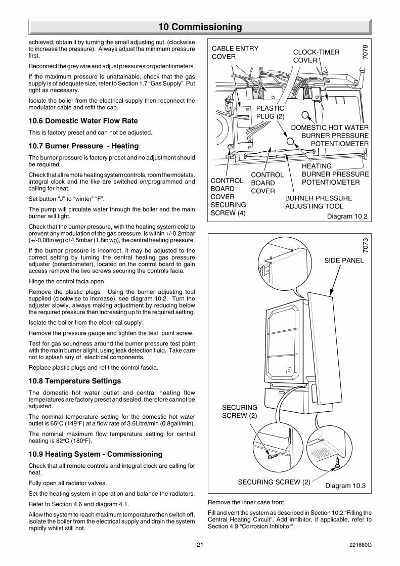
If the burner pressure is incorrect, it may be adjusted to thecorrect setting by turning the central heating gas pressureadjuster (potentiometer), located on the control board to gainaccess remove the two screws securing the controls facia.
Hinge the control facia open.
Remove the plastic plugs. Using the burner adjusting toolsupplied (clockwise to increase), see diagram 10.2. Turn theadjuster slowly, always making adjustment by reducing belowthe required pressure then increasing up to the required setting.
Isolate the boiler from the electrical supply.
Remove the pressure gauge and tighten the test point screw.
Test for gas soundness around the burner pressure test pointwith the main burner alight, using leak detection fluid. Take carenot to splash any of electrical components.
Replace plastic plugs and refit the control fascia.
10.8 Temperature Settings
The domestic hot water outlet and central heating flowtemperatures are factory preset and sealed, therefore cannot beadjusted.
The nominal temperature setting for the domestic hot wateroutlet is 65oC (149oF) at a flow rate of 3.6Litre/min (0.8gall/min).
The nominal maximum flow temperature setting for centralheating is 82oC (180oF).
10.9 Heating System - Commissioning
Check that all remote controls and integral clock are calling forheat.
Fully open all radiator valves.
Set the heating system in operation and balance the radiators.
Refer to Section 4.6 and diagram 4.1.
Allow the system to reach maximum temperature then switch off,isolate the boiler from the electrical supply and drain the systemrapidly whilst still hot.
Diagram 10.2
CABLE ENTRYCOVER
CLOCK-TIMERCOVER
CONTROLBOARDCOVER
BURNER PRESSUREADJUSTING TOOL
DOMESTIC HOT WATERBURNER PRESSURE
POTENTIOMETER
HEATINGBURNER PRESSUREPOTENTIOMETER
PLASTICPLUG (2)
CONTROLBOARDCOVERSECURINGSCREW (4)
Diagram 10.3
7073
SIDE PANEL
SECURING SCREW (2)
SECURINGSCREW (2)
Remove the inner case front.
Fill and vent the system as described in Section 10.2 “Filling theCentral Heating Circuit”. Add inhibitor, if applicable, refer toSection 4.9 “Corrosion Inhibitor”.

22221680G
10 Commissioning
Diagram 10.5
7074
NUT (2)
OUTERCASEFRONT
Diagram 10.4
7235
SECURING SCREWS
CUTOUT
CASEBASE
CUTOUT
WRAP AROUNDLower the pressure to the initial cold fill design pressure, usingthe external draining tap, close to the boiler, refer to Table 1 andSection 4.10.
10.10 Completion
Refit the inner case front.
Fit the side panels, hook into the threaded lugs at the top, seediagram 10.3.
Fit the case base, slide back engage the rear lugs, secure withtwo screws supplied, see diagram 10.4.
Secure the side panels at the bottom with the four screws, seediagram 10.3.
Fit the outer case front by locating it on one side then wrap itaround locating it on the opposite side, slide down locating onto the threaded lugs at the top and behind the controls cover atthe bottom, secure with nuts ,see diagram 10.5.
Set the boiler and any remote heating control to the desiredsettings, then close the control cover door.
10.11 Instruct the User
Instruct and demonstrate the lighting procedure, then advisethe user of the efficient and safe operation of the boiler.
Instruct and demonstrate the operation of any heating systemcontrols.
Advise the user that to ensure the continued efficient and safeoperation of the appliance it is recommended that it is checkedand serviced at regular intervals. The frequency of servicing willdepend upon the particular installation and usage, but in generalonce a year should be enough.
Draw attention, if applicable, to the current issue of the GasSafety (Installation and Use) Regulations, Section 35, whichimposes a duty of care on all persons who let out any propertycontaining a gas appliance.
It is the Law that any servicing is carried out by a competentperson.
Advise the user of the precautions necessary to prevent damageto the system and building in the event of the heating systembeing out of use during frost and freezing conditions.
Reminder - Leave these instructions and the “Benchmark”logbook with the user.
LARGEADJUSTING NUT(MIN PRESSURE)
2344
Diagram 10.6
SMALLADJUSTINGNUT (MAXPRESSURE)
TEST POINT
ELECTRICALCONNECTOR(GREY)
SPINDLE
SCREWCAP

23 221680G
11.1 Servicing or Replacing Parts
To ensure the continued efficient and safe operation of theboiler it is recommended that it is checked and serviced asnecessary at regular intervals.
The frequency of servicing will depend upon the particularinstallation conditions and usage, but in general once a yearshould be enough.
The servicing of this boiler must be carried out by a competentperson in accordance with the rules in force in the countries ofdestination.
NOTE: To obtain a products of combustion reading, removethe screw from the analyser probe positioned on the top of theboiler next to the flue elbow, see diagram 8.5. After use replacethe screw.
Typical values for this boiler at maximum domestic hot waterdemand is:- CO2 7.5% to 8.0% and CO 0.005% to 0.015%.These are based on a 300mm length rear flue.
Make sure the appliance does not modulate whilst checkingcombustion and allow the appliance to warm up for five minutesbefore taking a reading.
Unless stated otherwise, parts removed or renewed duringservicing should be fitted in the reverse order to removal.
After completing any servicing, or renewing of gas carryingcomponents, ALWAYS test for gas soundness and carry outfunctional checks of controls.
Dispose of all used sealing washers, gaskets and “O” ringswhen renewing components.
Use the new ones supplied with the replacement.
11.2 Data Label
The data label is positioned on the front of the inner case cover.
11 General Data
11.3 Isolation of Boiler
Before starting any servicing or the replacement of parts, isolatethe boiler from the electrical supply at the external isolator.
When servicing or replacing any cold/hot water or heating systemcomponents close all water cocks and drain appliance.
Close the gas service cock, see diagram 6.1.
BEFORE DRAINING THE BOILER, REFER TO SECTION 11.6.
11.4 Outer Case Front Removal
Remove the two nuts securing the outer case front then lift upunhook the case at the top from the threaded lugs, pull it off onone side to release then remove, see diagram 10.5.
11.5 Inner Case Front
Remove the inner case, secured by four screws, see diagram8.1.
11.6 System Pressures and Draining
All parts containing water of the central heating circuit within theboiler, are under the system pressure. Before any parts of thiscircuit are disconnected, reduce the system pressure at theexternal draining tap, turn the central heating isolating valves off,and drain at the drain points on the appropriate valves, seediagram 6.1.
All water containing parts of the domestic hot water circuit of theboiler will be under the supply water pressure. Before any partsof this circuit are disconnected, turn the domestic cold waterisolating valve off, open the hot water taps to reduce the waterpressure in the boiler and drain the boiler at the valves, seediagram 6.1.
After replacing any water containing part of the central heatingcircuit, make up the water loss, vent all air and pressurise thesystem. Refer to “Commissioning” in the Installation Instructions.
Check for water soundness and that the safety valve seatswithout leaking.
12 Servicing
12.1 Pilot Check
Check if the pilot flame is burning correctly and of the correctsize, see diagram 14.4. If the pilot flame is not correct, the pilotinjector will require removing when accessible.
12.2 Isolation and Access
Before starting, refer to Section 11.
Remove the fan from the flue collector, refer to Section 14.1
Remove the flue collector, secured with two screws.
Remove the main burner, refer to Section 14.2.
12.3 Cleaning the Heat Exchanger
Place a sheet of paper in the combustion chamber to cover theinjector and pilot assembly, to collect any debris.
Brush the heat exchanger.
Remove the paper together with any debris.
Do not use a brush with metal bristles.
12.4 Cleaning the Main Burner
Use a vacuum cleaner or suitable brush to clean the burnerthoroughly, making sure that all the burner ports are notobstructed.
Do not use a brush with metal bristles.
12.5 Cleaning the Pilot Injector
If the pilot flame was not burning correctly, it is necessary toremove the pilot injector, refer to Section 14.6.
Inspect the injector and clean if necessary, by blowing clearonly.
Do not use a wire or sharp instrument.
12.6 Service Checks
Inspect the pilot burner, spark electrode, adapter olive on thepilot tube and thermocouple. Clean if necessary or renew, referto Section 14.4, 14.5 and 14.6.
Check the main injector, cleaning or renewing as necessary,refer to Section 14.3.
Before replacing any parts removed during servicing, inspectthe condition of all seals and joints, renewing as necessary.
Check the condition of the combustion chamber insulation. Ifrenewing, refer to Section 14.20.
Check the spark gap, upon assembly, see diagram 14.4.

24221680G
Diagram 13.1
7025
CLOCK/TIMERPLUG
LINK
CLOCK/TIMER
12.7 Operational Checks
Check the safety valve manually by turning the knob in thedirection of the arrow.
Light the boiler, carry out operational checks and any necessaryadjustments as described in Commissioning in the InstallationInstructions.
12 Servicing
13.1 Initial Checks
If the boiler fails to operate, first check the following:-
1) That the electrical supply is available at the boiler and thefuses are in order. The mains light should be ON. If not isolatethe boiler from the electrical supply.
Test for continuity, at mains.
NOTE: THE BOILER CONTROL BOARDS CAN BE DAMAGEDBY INCORRECT TESTING OF COMPONENTS AND WIRINGWITH THE POWER ON.
2) Make sure that the system pressure gauge registers 0.7bar,minimum, and that the automatic air vent works. Refer toInstallation Instructions, Section 10.2.
3) That the gas supply is available at the boiler and purged ofair.
4) That the boiler is set for the required service.
5) With the boiler Summer/Winter Button “J” set to summer “H”,see diagram 4 User Instructions, check that the domestic watersupply is available and water flows freely from the hot taps.Close the taps.
6) With the boiler Summer/Winter Button “J” set to Winter “F”,see diagram 4 User Instructions, check that all heating systemcontrols, if fitted, are working correctly and calling for heat.
7) Check Summer/Winter Button “J” is set to Winter “F”, seediagram 4 User Instructions. Turn on a domestic hot water drawoff tap to create a demand.
Allow the boiler and system to cool down waiting at least aminimum of four minutes before pressing Summer/Winter Button“J” to set to Winter “F”.
If this is satisfactory proceed with the detailed fault finding asSection 13.3.
13.2 Clock/Timer
If the clock has failed it can be bypassed by disconnecting theplug and reconnecting the link, see diagram 13.1.
Gain access by removing the two screws securing the controlsfacia, see diagram 10.1.
Hinge the control facia forward.
Remove the clock timer cover, see diagram 9.1.
Disconnect the clock wiring harness plug and connect the link.
This is a temporary measure and the clock should be repairedor replaced as soon as possible.
13.3 Electrical
Preliminary electrical system checks, as outlined in a MultimeterInstruction book, are the first checks to be carried out during afault finding procedure.
Isolate the boiler from the electrical supply, refer to Section11.3.
Gain access to the boiler controls by removing the outer casefront, refer to diagram 10.5.
Remove the two screws securing the controls facia, see diagram9.1.
Hinge the control facia forward.
Remove the cable entry cover, see diagram 10.2.
Remove the controls cover
Check that all cables and connectors are secure.
Check all cables at the multipin connectors on the board.
Test the fuse on the main control board and renew as necessary.Fuse F1 type (T2A and F2 T315mA). If a fuse fails repeatedlyor the initial fault-finding checks described in Section 13.1indicate a boiler fault, check the boiler electrical circuits andfollow the fault finding procedures, see diagram 13.2 mainsfunctional flow, 13.3 pilot fault finding, 13.4 boiler fault finding13.5 thermocouple fault finding and for clock/timer fault finding,diagrams 13.6 and 13.7.
On completion of a fault finding task that has required thedisconnection and making of electrical connections then checks,for earth continuity, polarity and resistance to earth must becarried out.
Before replacing any part please read points below:-
Replacement of parts must only be carried out by a competentperson.
1. Refer to Section 11.1.
2. Always isolate the boiler from the electrical and as required,the gas supply, as Section 11.3.
3. On completion, make good any water loss and pressurise thesystem to initial design pressure, refer to “Commissioning” inthe Installation Instructions.
Before starting refer to Section 11.1
Isolate the boiler from the electrical supply, refer to Section11.3.
13 Fault Finding
12.8 Completion
Hook the outer case front on the top and secure with the nutspreviously removed, see diagram 10.5.

25 221680G
13 Fault Finding
7468
7495
Diagram 13.2LOW VOLTAGEFUNCTIONAL FLOW
TO TEST FOR COMPONENT OPERATION / FAILURE
Power to the appliance :- Test for 230V~ across live (brown)and earth (yellow and green), 230V~ across live and neutral(blue), and zero potential across neutral and earth.
Thermistors :- With the power off unplug the connector andtest resistance is 10kΩ at 25°C.
Domestic Hot Water demand sensor :- With a tap open thesupply to the sensor measure between the red and blackcables on X5a should be 12Vdc. The signal from the sensormeasured between the white and black cables X5a should bebetween 1Vdc and 11Vdc dependent of the flow rate.
Overheat thermostat :- With the power off unplug theconnectors and test for continuity (zero resistance).
Power to the gas control valve :- With a demand on test forvoltages of 230Vac ~ across the red and purple cableconnectors and 24Vdc~ across the grey and grey cableconnectors. When burner pressure at maximum.
Power to the fan :- With a demand on and the front coverremoved test for 230V~ at the fan connectors at high speedand 108V at low speed
Fan failure :- with the power off and the supply leads to thefan disconnected (pull the boots only) the resistance acrossthe fan coil should be 45Ω to 50Ω.
Pump :- With the power off unplug the connector from thepump. Restore the power and check that there is 230V~between live (brown) and neutral (blue) or live and theappliance earth.
Air pressure switch :- This is a change over device. Withthe fan at pilot only there should be 230Vac at the C and NC(No air state terminals. With the appliance running and thefan at full speed there should be 230Vac at C, Nc and No (AirState).
Water pressure switch :- With no water pressure and PowerOn, check there is 230V~ on the black and grey cables and0V on the grey cable X5b. With water applied to the systemand power on, check there is 230V~ on the black and greycables and on the white cable X5b. This will prove operationof the water pressure switch.
MAINS FUNCTIONAL FLOW
F12AT
red
red
red red
purple
brown
yellow
blue
brown
brown brown
brown
blue
N
OVERHEATCUTOFF
CO
NT
RO
L B
OA
RD GAS
VALVE
ON/OFFSWITCH
TERMINALBLOCK
PERMANENTMAINS 230V-50HZ
FAN
PUMP
TRANSFORMER240/24V
24VLOW
VOLTAGE
X3
X3
X4
X4
X3
X3
X2
X2
X2
X2
X2
X2
X2
X2
L
N/C
N/O
N/C2
N/O4
Cgrey
red
violet
AIR PRESSURESWITCH
X5b
X5b
X5b
C1grey
black
blue
white
LOW WATERPRESSURESWITCH
FAN SPEEDRESISTOR brown
3.15AT
grey
grey
red
white
black
X6
X6
X6
MODULATINGVALVE
DHWFLOW
SENSOR
purple
purple
DHW THERMISTOR
orange
orange
orange
orange
X6
X1
X1
CH THERMISTOR
24v~C
ON
TR
OL
BO
AR
D
X5a
X5a
X5a
X5a
X5a

26221680G
PILOT WILL NOT LIGHTSTART HERE
Check gas line-open all cocks,rectify any blockages, purge out any air. Does pilot light?
Apply match to pilot burner insteadof pressing piezo unit button.Does pilot light?
Undo tubing nut at pilot burner.Turn gas valve knob to Pilot/Ign.Press multi-functional control knob.Does gas flow freely?
Rectify blockage in pilot injector,or renew pilot injector.
Undo tubing nut at pilot outletof the multi-functional control.Press gas valve knob.Does gas flow freely?
Rectify or replaceblocked pilot tube.
Change multi-functional control.
Does pilot stay alight whenmulti-functional control knob is released?
PILOT SATISFACTORY
Does pilot flame envelop thermocouple?
Check aeration. If necessary -Clean pilot, rectify blockage inpilot injector, or replace.
Check thermocouple circuit usingThermocouple fault finding diagram.
On pressing piezo unit button isthere a spark across electrode gap?
Pull ignition lead off electrode. Hold end of lead close to pilot burner and operate piezo unit. Is there a spark across gap?
Is there continuity of piezo earth?
Repair or replace earth lead.
Pull ignition lead off piezo unit.Using blade of a screwdriver, touch unit chassis and leave approx. 4mm gap from connection tag onpiezo unit. Operate piezo.Is there a spark across gap?
Changepiezo unit.
Changeignition lead.
Check electrode gap. Reposition,or replace electrode as necessary.
NO YESNO YES
NO YES
NO YES
NO YES
NO YES
NO YES
NO YES
YESNO
NO YES
13 Fault Finding
Diagram 13.3
7460
PILOT FAULT FINDING

27 221680G
Check that gas,water and electricity are available at the boiler. There must be no externalvoltage applied to the control board via the central heating controls to the P.C.B.
Before commencment of test, isolate the boiler electricity supply,ensure that the remote controls are not calling for duty (no red link in terminal block)
Refer to functional flow diagrams in conjuction with the following fault finding.
START
Remove the outer case, lower the control housing and remove cable restraints.Check all connections on the control board and the boiler components,rectify or renew as necessary. Two spare fuses are provided.
Can pilot be lit? Refer to pilot fault finding.
Switch on main supply.Do mains and wintermode LEDs illuminate?
Change P.C.B.
Does low waterpressure LED flash?
Is there enoughsystem pressure?
Is there continuitybetween commonand N/O?
ChangeP.C.B.
Re-pressurisesystem.
Change waterpressure switch.
Does fan run atlow speed?
Is there 112v atfan terminals?
Is the 1kohmresistor OK?
ChangeP.C.B.
Change fan.Change fanresistor.
Winter ModeContinued.
Summer ModeContinued.
YES
YES
YES
NONO NO
YESYES NO
NO
NO
YES YES YES
NO NO YES
13 Fault Finding
Diagram 13.4
7491
BOILER FAULT FINDING

28221680G
Press button to changeto summer mode.Does summer modeLED illuminate?
Change P.C.B.
Turn hot water demand on.Does fan goto fast speed?
Using spare flow sensor.Connect to P.C.B.Then blow down flow sensor.Does the fan goto fast speed?
Change flowsensor.
ChangeP.C.B.
Does main burner light?Does signal atair pressure switchchange over?
Change airpressure switch.
Is there 230v atmain valve?
Change P.C.B.
Change the gas valve.
Is there a mV signalat the modureg? Change P.C.B.
Change gas valve.
Summer ModeContinued.
YES
Winter ModeContinued.
YES
YES
YES
YES
Connect a manometerto gas valve and checkburner pressure. Adjusthot water burner pressurepotentiometer. Does burnerpressure adjust accordingly?
YES
NO
NO
NO NO
NO
YES
NO NO
YES
NO
Is there a decrease inelectrical resistance acrossthe hot water thermistor astemperature rises?
Change thermistor.
Turn off hot water demand.Does main burner go out? Is there 230v
at main valve?
Change the valve.
Does central heatingpump start and run fora short time?
Is there 230vat pump?
ChangeP.C.B.
Change pump.
OK.
YES
YES
YES
YES
YES
NO
NO
NO
Change the P.C.B.YES
NONO
13 Fault Finding
Diagram 13.4
7492
BOILER FAULT FINDING
29 221680G
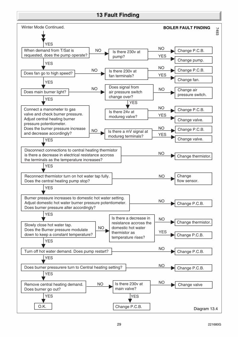
When demand from T/Sat isrequested, does the pump operate?
Is there 230v atpump?
Change pump.
Does fan go to high speed?
Does main burner light?Does signal fromair pressure switchchange over?
Winter Mode Continued.
YES
YES
YES
YESYES
NOYES
Change P.C.B.NO
Is there 24v atmodureg valve?
Change valve.YES
Change P.C.B.NO
Is there 230v atfan terminals?
Change fan.
Change airpressure switch.
YESChange P.C.B.
NONO
NO NO
Connect a manometer to gasvalve and check burner pressure.Adjust central heating burnerpressure potentiometer.Does the burner pressure increaseand decrease accordingly? Is there a mV signal at
modureg terminals?
Change P.C.B.
Disconnect connections to central heating thermistoris there a decrease in electrical resistance accrossthe terminals as the temperature increases?
Change thermistor.
Reconnect thermistor turn on hot water tap fully.Does the central heating pump stop?
Changeflow sensor.
Burner pressure increases to domestic hot water setting.Adjust domestic hot water burner pressure potentiometer.Does burner pressure alter accordingly?
Change P.C.B.
Slowly close hot water tap.Does the Burner pressure modulatedown to keep a constant temperature?
Is there a decrease inresistance accross thedomestic hot waterthermistor astemperature rises?
Change thermistor.
YES
YES
YES
YES
YES
NONO
Change valve.YES
NO
NO
NO
NO
NO
Change P.C.B.YES
Turn off hot water demand. Does pump restart? Change P.C.B.
Does burner pressurere turn to Central heating setting?
Remove central heating demand.Does burner go out?
Is there 230v atmain valve?
Change valve
O.K. Change P.C.B.
YES
YES
YES YES
NO
Change P.C.B.NO
NO NO
13 Fault Finding
Diagram 13.4
7493
BOILER FAULT FINDING

30221680G
With the boiler cold, check connections of the thermocouple, boiler overheat cut-off and gas valve.Disconnect overheat cut-off connectors at points A and B at the gas valve, see diagram.Test continuity of the overheat cut-off. Is there continuity?
Test continuity of thermocouple between innerpoint D and point E. Is there continuity?
Re-connect boiler overheat cut-off to points A and B.Disconnect thermocouple at point D of the gas valve.Test continuity between point C and the body of thegas valve. Is there continuity?
YES
Thermocouple and boiler overheat circuit satisfactory.
Faulty cut-off connectors into gas valve. Either at A or C.Renew where faulty.
Faulty thermocouple, renew.
Faulty boiler overheat cut-off,renew.
YES
NO
NO
YES
NO
13 Fault Finding
Diagram 13.5THERMOCOUPLE FAULT FINDING
2313
S
CONNECTION 'C'
GASCONTROLVALVE
CONNECTION 'A'
CONNECTION 'E'
BOILEROVERHEATCUT-OFF
CONNECTION 'D'
CONNECTION 'B'
7462

31 221680G
Check continuity of clock/timer harness, ensure an electrical supply is available at the clock,ensure that remote controls are calling for heat, ensure the override switch, if fitted, is in overide position.
NB. The clock can be by passed by refitting the plug link which should be inside the clock timer cover.
Isolate electrical supply, set clock to an on period.Is there continuity across common and heating?
Does clock keep time? NO
Clock/timer in order if no central heating,refer to main fault finding.
Set clock to off period. Is there continuity across common and heating on?
NO
Faulty clock/timer.Replace.
NO Faulty clock/timer.Replace.
Faulty clock/timer.Replace.
YES
YES
YES
Check continuity of clock/timer harness, ensure an electrical supply is available,ensure that remote controls are calling for heat.
NB. The clock can be by passed by refitting the plug link which should be inside the clock timer cover.
Isolate the boiler from electrical supply remove outer case.
Disconnect and insulate the cablesfrom heating common and heating on.
Switch on electrical supply,is there a display on clock/timer?
NO
Clock/timer in order if no central heating,refer to main fault finding.
Advance clock/timer until a demand is indicatedIs there now continuity between heatingcommon and heating on?
YES
Faulty clock/timer.Replace.
Faulty clock/timer.Replace.
YES
YES
YES
NO
ELECTRO/MECHANICAL FAULT FINDING Diagram 13.7
7463
13 Fault Finding
DIGITAL FAULT FINDING Diagram 13.6
7461
BLU
E
BR
OW
N
PU
RP
LE
OR
AN
GE
(N) (L)
EXTERNALCONTROLS
PLUG FROM CLOCK/TIMER
7684

32221680G
14.1 Fan
Before starting refer to Section 11.
Disconnect the two electrical connectors at the fan by pulling theboots not the wires, see diagram 8.2.
Disconnect the two air pressure switch flexible tubes from thefan.
Remove the fan, secured with two screws at the front and gentlyease the fan from the flue elbow and rear bracket.
To fit the fan, locate it into the rear bracket and ease the fan intothe flue outlet, secure with the two screws.
The polarity of the two electrical connectors is not important.
14.2 Main Burner
Before starting refer to Section 11.
Remove the two screws securing the flue collector, see diagram14.1.
Remove the combustion chamber front panel, secured with fourscrews.
Open the controls cover door, see diagram 4.
Remove the two screws securing the controls facia, see diagram9.1.
Hinge the control facia open.
Separate the pilot assembly from the main burner secured withtwo screws and washers, see diagram 14.2.
Remove the sealing gland, see diagram 14.2.
Remove the burner bracket securing screw, wing nut andbracket, see diagram 14.2.
Remove the main burner from the main injector at the rear. Tiltthe burner up and slide in channel forwards, easing the pilotassembly forwards to clear, taking care not to damage thecombustion chamber insulation or the pilot burner assembly.
When refitting make sure that the main burner is fitted correctlyon assembly, located on the main injector and horizontal, thetips of the rearmost blade under the two burner guides.
Locate the combustion chamber front panel under the frontedge of the flue hood on assembly, then secure all screws andwing nut.
Test pilot for gas soundness with suitable leak detection fluidwith the gas control knob depressed.
14.3 Main Injector
Before starting refer to Section 11.
Remove the main burner, refer to Section 14.2.
Unscrew the main injector, see diagram 14.3.
Fit the new sealing washer supplied, to ensure gas soundness,when fitting the main injector.
14.4. Pilot Burner
Before starting refer to Section 11.
Remove the main burner refer to Section 14.2.
Remove the sealing angle, secured with a single screw, seediagram 14.2.
Remove the spark electrode, secured with a spring clip, seediagram 14.2.
Disconnect the thermocouple nut from the pilot burner.
14 Replacement of Parts
Diagram 14.1
7249
WINGNUT
COMBUSTIONCHAMBERFRONT PANEL
FLUECOLLECTOR
SCREW (4)
SECURINGSCREW (2)
Diagram 14.2
SPARKELECTRODE
IGNITIONLEAD
PILOT INJECTOR
SPARKELECTRODERETAINING CLIP
THERMO-COUPLENUT
PILOT TUBENUT
WING NUT
SECURINGSCREW ANDWASHER (2)
SEALING GLANDSECURING SCREW
4583
SECURINGSCREW
BURNER BRACKET

33 221680G
Disconnect the pilot supply tube, holding the pilot injectorhexagon with another spanner, then remove the pilot burner.
Check the spark gap upon assembly, see diagram 14.4.
Make sure the pilot injector is fitted.
Test joints for gas soundness with suitable leak detection fluidwith the gas control knob depressed.
14.5 Spark Electrode
Before starting, refer to Section 11.
Slacken the sealing angle, secured with a single screw, seediagram 14.2.
Remove the spark electrode, secured with a spring clip, seediagram 14.2.
Ease the spark electrode through the sealing angle.
Open the controls cover door. Remove the two screws securingthe controls facia, see diagram 9.1.
Hinge the control fascia open.
Disconnect the ignition lead from the piezo unit, see diagram14.9.
Check the spark gap upon the assembly, see diagram 14.4.
14 Replacement of Parts
Diagram 14.4
SPARK GAP 4.5mmto 5.5mm
FLAMELENGTH25mm
4574
Diagram 14.3
7311
COPPERWASHER
MAININJECTOR
7079
Diagram14.5
ACCESSCOVER SECURING
SCREW (3)
SHORT SECURINGSCREW (2)
LONG SECURINGSCREW (2)
PILOT TUBENUT
THERMOCOUPLENUT
OVER HEATCUTOFFELECTRICALCONNECTION
OVER HEATCUTOFF
SHORT SECURINGSCREW (2)
WARNING 230V 50HzELECTRICALCONNECTION (5)
GASCONTROLVALVE

34221680G
14 Replacement of Parts
14.6 Pilot Injector
Before starting, refer to Section 11.
Remove the sealing angle, secured with a single screw, seediagram 14.2.
Remove the spark electrode, secured with a spring clip, seediagram 14.2.
Disconnect the thermocouple nut from the pilot burner.
Disconnect the pilot supply tube, holding the pilot injectorhexagon with another spanner, then remove the pilot burner.
Remove the pilot injector from the pilot assembly by unscrewingit.
Check the pilot flame length on relighting, see diagram 14.4.
Test pilot for gas soundness with suitable leak detection fluidwith the gas control knob depressed.
14.7 Thermocouple
Before starting refer to Section 11.
Open the controls cover door. Remove the two screwssecuring the controls facia, see diagram 9.1.
Hinge the control fascia open.
Remove the main burner, refer to Section 14.2.
Remove the sealing angle secured with a single screw, seediagram 14.2.
Remove the access cover in the base of the combustionchamber secured with three screws, see diagram 14.5.
Disconnect the thermocouple at the gas control valve and pilotassembly, see diagram 14.2 and 14.5.
Remove the thermocouple.
Make sure that the overheat cutoff connector is in place in theslot of the gas control valve when fitting the thermocouple. Donot tighten the thermocouple nut more than a quarter turnbeyond finger tight or make any tight bends in the thermocouplecapillary.
Test joints for gas soundness with suitable leak detection fluidwith the gas control knob depressed.
14.8 Central Heating Boiler Overheat Cutoff
Before starting refer to Section 11.
Open the controls cover door. Remove the two screwssecuring the controls facia, see diagram 9.1.
Hinge the control fascia open.
Disconnect the overheat cutoff electrical connectors positionedat the front and rear of the gas control valve, see diagrams 14.5and 14.7.
Unclip to remove the overheat cutoff, see diagram 14.8.
14.9 Domestic Hot Water Boiler OverheatCutoff
Before starting refer to Section 11.
Open the controls cover door, see diagram 4 user instructions.
Remove the two screws securing the controls facia, seediagram 9.1.
Hinge the control fascia open.
Disconnect the overheat cutoff electrical connectors, seediagram 14.8.
Remove the securing screws to release the overheat cutoff.
14.10 Domestic Hot Water Thermistor.
Before starting, refer to Section 11.
Open the controls cover door. Remove the two screws securingthe controls facia, see diagram 9.1.
Hinge the control fascia open.
Disconnect the electrical connector at the domestic hot waterthermistor, see diagram 14.8.
Unclip the domestic hot water thermistor from the flow pipe.
14.11 Central Heating Hot Water Thermistor.
Before starting, refer to Section 11.
Open the controls cover door. Remove the two screws securingthe controls facia, see diagram 9.1.
Hinge the control facia forward.
Disconnect the electrical connector at the domestic hot waterthermistor, see diagram 14.8.
Unclip to remove the domestic hot water thermistor from theflow pipe.
14.12 Transformer
Before starting, refer to Section 11.
Open the controls cover door. Remove the two screws securingthe controls facia, see diagram 9.1.
Hinge the control fascia open.
Disconnect the inline electrical connectors from the transformer,see diagram 14.8.
Remove the transformer, noting the correct position.
To connect the transformer cables correctly, see diagram14.25.
14.13 Fan Resistor
Before starting, refer to Section 11.
Disconnect the electrical connectors from the resistor, seediagram 14.6.
Remove the resistor, noting the correct position.
To connect the resistor cables correctly, see diagram 14.25.
14.14 Piezo Unit
Before starting refer to Section 11.
Open the controls cover door. Remove the two screws securingthe controls facia, see diagram 9.1.
Hinge the control fascia open.
Disconnect the ignition and earth leads at the piezo unit.
Remove the piezo unit, see diagram 14.9.

35 221680G
14 Replacement of Parts
7097
Diagram 14.7
7034
Diagram 14.8
ELECTRICALCONNECTION
GASCONTROLVALVE
TRANSFORMER
BOILER OVERHEATCUTOFF CENTRALHEATING
DOMESTIC HOT WATERTHERMISTOR
CENTRAL HEATINGHOT WATERTHERMISTOR
WATERPRESSURESWITCH
RETAINING CLIP
ELECTRICALCONNECTION
GAS CONTROLVALVE
Diagram 14.672
36
FANRESISTOR
RETAININGBRACKET
ELECTRICALCONNECTION (2)
Top right hand side of boiler
BOILER OVERHEATCUTOFFDOMESTIC HOTWATER
7072
Diagram 14.9PIEZO UNIT
SECURINGNUT
IGNITIONLEAD
EARTHLEAD
7237
Diagram 14.10
CAREFULLY BEND THERETAINING CLIPS FORWARDTO RELEASE MULTI PINCONNECTORS
MULTI PINCONNECTORS
SECURINGSCREW (2)

36221680G
14 Replacement of Parts
14.15 Control Board
Before starting refer to Section 11.
Open the controls cover door. Remove the two screws securingthe controls facia, see diagram 9.1.
Hinge the control fascia open.
Remove the cable entry covers, see diagram 10,2.
Disconnect the multi-pin connectors retained by clips, seediagram 14.10.
Remove the controls board cover securing screws and removecover, see diagram 10.2.
Disconnect the remaining multi-pin connector retained by a clip.
Remove the control board securing screw, see diagram 14.11.
Remove the control board from the support posts, see diagram14.11.
THE MAIN CONTROL BOARD MUST BE KEPT IN THE ANTISTATIC HOLDER UNTIL IMMEDIATE REQUIREMENT.
When replacing the main control board check and if necessaryadjust the main burner gas pressure in both the hot water andcentral heating modes. Refer to “Commissioning” in theInstallation Instructions.
4.16 Pressure Gauge
Before starting, refer to Section 11.
Open the controls cover door. Remove the two screws securingthe controls facia, see diagram 9.1.
Hinge the control fascia open.
Release the water pressure and drain the central heating circuitof the boiler, refer to Section 11.3 and 11.6.
Disconnect the pressure gauge connection from the safetyvalve, discard the washer, see diagram 14.12.
Remove the pressure gauge, see diagram 14.13.
Locate the supplied washer under the pressure gauge connectionwhen refitted to the safety valve.
IMPORTANT NOTE: Make sure the capillary follows the originalroute avoiding kinks and sharp bends.
7238
Diagram 14.11
14.17 Gas Control Valve
Before starting refer to Section 11.
Remove the case base, see diagram 10.4.
Open the controls cover door. Remove the two screws securingthe controls facia, see diagram 9.1.
Hinge the control fascia open.
Remove the main burner refer to Section 14.2.
Remove the gas control knob.
Remove the access cover in the base of the combustionchamber secured with three screws, see diagram 14.5.
Disconnect the five electrical connectors, four at the front of thegas control valve and one at the rear, see diagrams 14.5 and14.7.
Disconnect the thermocouple at the gas control valve, seediagram 14.5.
Disconnect the pilot supply tube at the gas control valve, seediagram 14.5.
Disconnect the gas supply union at the gas service cock, seediagram 8.4.
Remove the four extended hexagon screws at the gas controlvalve, see diagram 14.5.
Pull the gas control valve forward releasing it from the two rearsupport pins.
Remove the four extended screws attaching the manifold to thegas control valve
Transfer the pilot tube adapter, overheat cutoff connectors andmanifold to the replacement valve. Discard the “O” rings and fitthe new ones supplied, when fitting the gas valve.
To connect the gas control valve cables correctly, see diagram14.25.
Light and adjust the boiler if necessary, refer to Commissioningin the Installation Instructions. Adjust the pilot flame if necessary,refer to Section 14.4, Pilot Burner.
Test joints for gas soundness with suitable leak detection fluidwith the gas control knob depressed.
Check and adjust the main burner pressure in the hot water andcentral heating modes, refer to Commissioning in the InstallationInstructions.
SUPPORTPOST (4)
SECURINGSCREW
MULTI PINCONNECTOR (5)

37 221680G
14 Replacement of Parts
Diagram 14.12
7089
Diagram 14.13
7026
SAFETYVALVE
WASHER
UNION NUT
SECURINGSCREW (2)
FASCIA
RETAININGBRACKET (2)
PRESSUREGAUGE
Diagram 14.1472
47
ELECTRICALCONNECTOR(2)
MODULATOR
SCREW(2)
GASCONTROLVALVE
GASKET
Diagram 14.15
7035
AUTOMATICBYPASS VALVE
UNION NUTS
14.18 Modulator
Before starting refer to Section 11.
Open the controls cover door. Remove the two screws securingthe controls facia, see diagram 9.1.
Hinge the control fascia open.
Disconnect the two electrical connectors at the modulator, seediagram 14.14.
Remove the modulator, secured with two screws.
Discard the gasket and fit the new one supplied with themodulator.
Light, check and adjust the boiler if necessary, refer toCommissioning in the Installation Instructions.
Test joints for gas soundness with suitable leak detection fluidwith the gas control knob depressed.
14.19 Automatic Bypass Valve
Before starting refer to Section 11.
Remove the case base, see diagram 10.4.
Open the controls cover door. Remove the two screws securingthe controls facia, see diagram 9.1.
Hinge the control fascia open.
Isolate the central heating flow and return, release the waterpressure and drain, refer to Section 11.3 and 11.6.
Remove the pressure automatic bypass valve by disconnectingthe union nuts, see diagram 14.15.
Discard the sealing washers and use the new ones supplied.
14.20 Safety Valve
Before starting, refer to Section 11.
Remove the case base, see diagram 10.4.
Open the controls cover door. Remove the two screws securingthe controls facia, see diagram 9.1.
Hinge the control fascia open.
Release the water pressure and drain, refer toSections 11.3 and 11.6.

38221680G
Diagram 14.16
7033
PUMP
CLIP
UNIONNUT
ENDSCREW
SPINDLE
SECURINGSCREW (4)
PUMPADJUSTER
PLUG
14 Replacement of PartsDisconnect the pressure gauge connection from the safetyvalve, see diagram 14.12.
Disconnect the union nuts to release the safety valve, seediagram 14.12.
Discard the sealing washers and use the new ones supplied, onassembly.
Make up water loss and pressurise the system, refer toCommissioning in the Installation Instructions.
14.21 Water Inlet Filter
Before starting refer to Section 11.
Remove the case base, see diagram 10.4.
Isolate domestic water inlet, release the domestic water pressureand drain by opening the draw off lowest tap, refer to Section11.3 and 11.6.
Disconnect the water inlet union nut to gain access to the filter,see diagram 8.4.
Clean or renew the filter as necessary.
Discard the sealing washer and use the new one supplied, onassembly.
14.22 Pump
Before starting refer to Section 11.
Open the controls cover door. Remove the two screws securingthe controls facia, see diagram 9.1.
Hinge the control fascia open.
Remove the electrical plug at the pump, see diagram 14.16.
Release the water pressure and drain, refer to Sections 11.3and 11.6.
Disconnect the pump at the top in the combustion chamber byremoving the union nut and clip, see diagram 14.16.
Rlease the union nut at the bottom of the pump, see diagram14.16.
It may be necessary to slacken the union nut at the automaticbypass and water cock.
Remove the pump.
Discard the sealing washer from the bottom fixing.
Make sure that the flow direction arrow is pointing upward, onthe pump, when fitting the pump to the lower pipework use thenew sealing washer provided.
Set the flow adjuster on the pump to maximum setting. The flowrate should be controlled by means of a valve in the heatingsystem.
Make up water loss and pressurise the system, refer toCommissioning in the Installation Instructions.
Note: Should the pump fail to work, see diagram 14.25. If all isin order but the pump still does not work, remove the screw, seediagram 14.16 then turn the pump spindle to release anytemporary seizure. DO NOT HIT THE SPINDLE.
14.23 Flow Sensor
Before starting refer to Section 11.
Remove the case base, see diagram 10.4.
Remove the main burner, refer to Section 14.2.
Refer to diagram 14.18.
Disconnect the domestic inlet pipe.
Remove the water flow sensor assembly.
Disconnect the electrical plug.
Unscrew the water flow sensor and remove.
Ensure sealing washers are in place when refitting.
14.24 Automatic Air Vent
Before starting refer to Section 11.
Release the water pressure and drain, refer to Sections 11.3and 11.6.
Remove the automatic air vent, see diagram 14.17.
Discard the sealing washer and use the new one supplied,when fitting.
Slacken the small cap on the air vent. This MUST NOT beretightened.
Make up water loss and pressurise the system, refer toCommissioning in the Installation Instructions.

39 221680G
14 Replacement of Parts
Diagram 14.17
UNION (4)
SEALINGWASHER
AUTOMATICAIR VENT
CAP
LOCATIONSLOT 72
48
Diagram 14.1872
46
WATER FLOWSENSOR
Diagram 14.19
7245
UNION NUT
UNION NUT
UNION NUT
CONNECTOR
AIRPRESSURETUBES
SECURINGSCREW (2)
ELECTRICALCONNECTION (3)
AIRPRESSURESWITCH
RED
WHITE
14.25 Air Pressure Switch
Before starting refer to Section 11.
Disconnect the electrical connectors at the microswitch, seediagram 14.19.
Disconnect the air pressure tubes.
Remove pressure switch see diagram 14.19.
14.26 Heat Exchanger
Before starting refer to Section 11.
Release the water pressure and drain the domestic hot waterand central heating, refer to Sections 11.3 and 11.6.
Remove the fan from the flue collector, refer to Section 14.1.
Remove the flue collector, secured with two screws, see diagram14.2.
Remove the combustion chamber cover, see diagram 14.1.
Remove the main burner, refer to Section 14.2.
Remove the automatic air vent, see diagram 14.17.
If renewing the heat exchanger, transfer the air vent to the newone, using the new sealing washers supplied.
Disconnect the union nuts of the heat exchanger to remove it.Take care there may be some water retained in the heatexchanger.
Discard the sealing washers and use the new ones supplied,upon assembly.
Locate the raised location tabs on the combustion chambersides into the slots on the heat exchanger, when fitting.
Make sure that the main burner is located on the main injectorand is horizontal, the tips of the rear most blade under the twoburner guides.
The combustion chamber front panel should be fitted loosely,then the flue collector also fitted loosely, ensuring that it isseated correctly on the heat exchanger and over the top edgeof the front panel.
Locate the fan into the flue elbow and the clip at the rear, thensecure with the two screws.

40221680G
Diagram 14.20
2268
S
SIDE INSULATION PIECES
LOWER REAR INSULATION
COMBUSTIONCHAMBERFRONT PANEL
FRONTINSULATION
CLIP
UPPERREARINSULATION
14 Replacement of Parts
Connect the cables, the polarity of the two connectors is notimportant.
Tighten the screws evenly to secure the flue collector andcombustion chamber front panel.
Make up water loss and pressurise the system, refer toCommissioning in the Installation Instructions.
14.27 Combustion Chamber Insulation
Before starting refer to Section 11.
Remove the combustion chamber front panel, secured with fourscrews and a wing nut.
Remove the front insulation panel, secured with a clip, seediagram 14.20.
Slide out both side insulation pieces.
Pull the lower rear insulation forwards, then slide the upper rearinsulation down from behind the heat exchanger.
To fit the flue collector, combustion chamber front panel andfan, refer to Section 14.1.
14.28 Expansion Vessel
Renewal of the expansion vessel requires the boiler to beremoved from the wall. As an alternative, a separate expansionvessel of the same specification may be connected as close aspossible to the boiler, leaving the original in position, refer to theInstallation Instructions.
Remove the outer case front, side panels and inner case front,refer to Sections 11.4 and 11.5.
Release the water pressure and drain the domestic hot waterand central heating, refer to Section 11.3 and 11.6.
Disconnect the boiler water connection union nuts at the frontof the isolating valves, see diagram 8.4.
Disconnect the gas service cock union.
Disconnect the safety valve discharge pipe from the boiler.
Disconnect the mains supply cable at the connector block onthe back of the controls fascia.
Remove the two screws at the service cock bracket. Pull theboiler from the isolating valves. Unhook the boiler at the top,easing the boiler from the flue outlet and lift off.
Carefully lay the boiler down on its side for access to theexpansion vessel.
Disconnect the union nut connection, see diagram 14.21 anddiscard the sealing washer for the new one supplied.
Remove the expansion vessel, secured with three clampingscrews.
Connect the union nut, when fitting the expansion vessel,before clamping it.

41 221680G
14 Replacement of Parts
Diagram 14.21
7400
7005
SECURINGSCREW (4)
PLUG
7002
GASKET
GLASS
Diagram 14.22
FRAME
SECURINGSCREW (2)
CLOCK /TIMER
LN
ELECTRICALCONNECTION (4)
SECURINGSCREW (3)
UNION NUT
EXPANSIONVESSEL
14.29 Mini Expansion Vessel (If fitted)
Remove the mini-expansion vessel.
When refitting use the new sealing washer supplied.
14.30 Viewing Window (Combustion Chamber)
Remove outer case front as section 11.4.
Remove the viewing window, secured with two screws. Whenfitting a new window use the gasket provided, see diagram14.22.
14.31 Viewing Window (Inner Case Front)
Remove the old self adhesive aluminium foil gasket and the oldmica window. Replace with a new mica window. Peel off thebacking paper and secure with new self adhesive aluminium foilgasket, see diagram 14.23. Ensure no air bubbles are trappedunderneath the foil.
Important
Make sure that the mica window fully covers the opening andthat the hole in the aluminium foil gasket is centred overopening.
14.32 Inner Case Front Seal
Remove outer case front as section 11.4.
Remove the old seal, clean out the old adhesive.
Glue the new seal into place, making sure that there are nobreaks in it..
14.33 Clock/Timer - if fitted
Before starting refer to Section 11.
Remove the two screws securing the controls cover door andcontrols facia, see diagram 9.1.
Hinge the assembly open.
Remove the clock-timer cover, see diagram 11.2.
ELECTRO/MECHANICAL and DIGITAL clock/timer - Releasesecuring screws, see diagram 14.24.
Disconnect electrical cables, remove the clock/timer, seediagram 14.24. Diagram 14.23
SELF ADHESIVEALUMINIUM FOILGASKET
7886OPENING
(BOILER INNERCASE FRONT)
MICA
PEEL OFFBACKINGPAPER
Diagram 14.24

42221680G
14 Replacement of Parts
Diagram 14.25
7683
bg
CONTROL BOARD
MAINS SWITCH
THERMISTOR(CENTRAL HEATING)
PIEZO
FANRESISTOR
WATERPRESSURE SWITCH
AIRPRESSURESWITCH
GASCONTROLVALVE
ELECTRODE
BOILER OVERHEATCUT-OFF FAN
THERMISTOR(DOMESTICHOT WATER)
230V-50HzPERMANENT
MAINS SUPPLYFUSED AT 3A
CHASSISEARTHG/Y
FUSEDAT 3.15A
FUSEDAT 2A
ROOM STATCLOCK TIMER
CN/CN/O
C1N/O4N/C2
PUMP
WATERFLOW
ENL
br
br
w
r
r
r
y
bk
w
bk
g g
g
br
br
br
X4
X2
X3 X5b X5a X6X1
p
or
or
r
br
b
pp
rr
or
or
orbr
b
g/y
p
g
v
b
rry
br
230V TRANSFORMER
PLUG PLUG
PLUG
PLUG
CHASSISEARTHG/Y
g/y
g/y
NOTE 2
1NOTE 1
2
CN/C
N/O
NOTE 1 Red link to be removed when external roomstat is used. 2 Plug C/W link to be removed when clock timer is used. (The removed plug to be left inside the clock timer cover.)
w- WHITE
b- BLUE
bk- BLACK
br - BROWN
g/y- GREEN/
g- GREY
or- ORANGE
r- RED
y- YELLOW
p- PURPLE
v- VIOLETYELLOW
KEY

43 221680G
15 Spare Parts
Key No. Part No. Description G.C. No.
1 457412 Fan assembly E26742
2 205765 Main injector assembly E26741
3 203433 Pilot burner 379485
4 202627 Spark electrode 278131
5 203518 Pilot injector 381656
6 202435 Thermocouple 378204
7 801183 Boiler overheat cutoff assembly E27356
8 202529 Domestic hot water limit control *****
9 202712 Piezo unit E26688
10 204546 Pressure gauge assembly E26683
11 227066 Control board (inc 16,17) *****
12 202810 Transformer E26700
13 801169 Gas Control valve assembly E26726
14 227003 Thermistor Domestic Hot Water *****
15 227002 Flow Sensor E04063
16 202226 Fuse 2 type T2A x 20mm 278136
17 202240 Fuse 1 type 3.15ATx 20mm 278414
18 227071 Air Pressure switch E26891
19 227083 Fan Resistor *****
20 457068 Low Water Pressure Switch E26723
21 227004 Thermistor Central Heating E26743
22 800153 Automatic Air Vent (inc seal) 313285
15.1 Part Identification
The key number in diagram 15.1 and the first column of the listwill help identify the spare part.
15.2 Ordering
When ordering any spare part, please quote the part numberand the description from the list together with the model nameand serial number information from the data label.
The data label is positioned on the inner case front, see diagram8.2 Installation Instructions.

44221680G
Because of our constant endeavour for improvement, details may vary slightly from those shown in these instructions.
Diagram 15.1
7267
15 Spare Parts
1
13 7
10
5
4
6
8
19 22
18
3
21
14
2
1512
20
9 16
17
11