gluex collaboration meeting 12gev trigger electronics 16 – 18 february 2012 r. chris cuevas
DESCRIPTION
GlueX Collaboration Meeting 12GeV Trigger Electronics 16 – 18 February 2012 R. Chris Cuevas. Hardware Design Status Updates We have the hardware! Production Status DAq and Trigger Testing New applications Global Trigger Hardware Testing Deployment Plans Summary. - PowerPoint PPT PresentationTRANSCRIPT

GlueX Collaboration Meeting
12GeV Trigger Electronics
16 – 18 February 2012
R. Chris Cuevas
1. Hardware Design Status Updates We have the hardware! Production Status
2. DAq and Trigger Testing New applications Global Trigger Hardware Testing Deployment Plans
3. Summary

Trigger Hardware Status
2
• GlueX- Doc - 614
Some history:
Seems like a shorttime ago, but halfa decade has passed,and an enormous amount of effort has gone into the development and construction of the new board designs for the 12GeV front-end DAq and Trigger systems.
New Engineers hired, Concepts to Copper,,,,,,,

Trigger Hardware Status
3
Front End Crate• FADC250, (FADC125), (F1TDC)• Crate Trigger Processor• Signal Distribution• Trigger Interface
Global Trigger Crate• Sub-System Processor• Global Trigger Processor
Trigger Control/Synchronization• Trigger Supervisor• Trigger Distribution
FADC250 CTP
SD TI
SSP GTP
TSTD
L1 Trigger ‘Data’MTP Ribbon Fiber
Trigger ‘Link” ControlClock, SyncMTP Ribbon Fiber

• Signal Distribution ( SD ) Production procurement has been approved – Jan-2012
Quantity of 124 SD boards for all Halls- 60 Hall D- 53 Hall B- 11 Halls A & C
Awaiting turn-key manufacturing bids Schedule to test production boards by May-2012
6 Pre-production boards have been manufactured, assembled and passed acceptance testing.
SD provides precision low jitter fan-out of 250MHz system clock, trigger and synch signals over VXS backplane to VXS payload modules
Latest SD version includes clock jitter attenuation PLL 2 pre-production boards are installed and running in the two crate test
station4
Trigger Hardware Status

• TI – TD Trigger Interface – Trigger Distribution Production procurement has been approved – Jan-2012
Quantity of 184* TI - TD boards for all Halls (*TD boards are included)
- 72 Hall D- 92 Hall B- 20 Halls A & C
Awaiting turn-key manufacturing bids Schedule to test production boards by May-2012
10 pre-production boards have been manufactured, assembled and passed acceptance testing.
Both TI and TD functions have been tested. Single TD can function as “TS” for multiple crate (9) configuration 2 pre-production boards are installed and running in the two crate test
station Circuit board is configured differently for TI or TD function
5
Trigger Hardware Status

Flash ADC 250Msps ( FADC250 ) Production order placed!! – See Fernando’s update Automatic board level verification test station is complete. CODA library ‘driver’ complete and is used in two crate DAq test station
• Crate Trigger Processor ( CTP ) Production order planned for Q4-FY12 Minor Engineering Changes before production
- 25 Hall D- 27 Hall B- 4 Halls A & C
We have 4 fully functional CTP modules 2 latest CTPs include FPGA that support higher Gigabit speed (5Gbp/s) FADC250-V2 Gigabit outputs verified with CTP @2.5Gb/s per lane! Sixteen FADC250 boards successfully tested in full crate! Successful test with two crate system at full 200KHz trigger rate!! Transports L1 trigger data over fiber to Global Trigger crate (SSP)
6
Trigger Hardware Status

• SubSystem Processor ( SSP ) Minor Engineering changes required before production order Plan to order production units Q4-FY12
- 8 Hall D- 14 Hall B- Spares?
Must be tested with GTP and TS to fully verify global trigger latency Prototype board has been tested and is ahead of schedule. SSP successfully used in two crate DAq testing SSP to GTP serial link definitions have been fully specified and
implemented for VXS Initial testing of SSP (Xilinx) => GTP (Altera) Gigabit transceivers is
successful Manages trigger information from up to 8 front end crates.
(2048 channels!) Trigger data received on front panel with fiber transceivers 10Gbp/s input capability ( 4 lanes @3.125Gbp/s*(8/10b) ) 10Gpb/s output stream to GTP on VXS backplane 7
Trigger Hardware Status

• Global Trigger Processor ( GTP ) (FY – 11/12) 1st Article GTP module has been fabricated, assembled and received The initial acceptance test plan is presently being executed and further
testing will be completed soon. Interface requirements to SSP and TS have been finalized The GTP transceivers (Altera) have been tested with the SSP
transceivers (Xilinx) over the VXS backplane without problems
Significant amount of firmware development and verification activity remains: Ethernet interface Implementation of final Physics Trigger equations Full test of Global Trigger Crate planned for June -2012
Production order not needed until Q1 - FY13- Total of 8 GTP for ALL Halls (2 per Hall includes 1 spare)
8
Trigger Hardware Status
9
Trigger Hardware Status • Trigger Supervisor ( TS ) (FY-11/12 activity)
William Gu has completed the schematic and board layout Design review completed 1st article has been fabricated, assembled and received
See William’s presentation Test plans include functional hardware verification with TD
and GTP modules Production order not needed until Q1 - FY13
- Total of 8 TS for ALL Halls (2 per Hall includes 1 spare)
New board format from legacy era – VXS Payload module Distributes precision clock, triggers, and sync to front end
crates via the Trigger Distribution modules. Manages global triggers and ReadOut Controller events Global Trigger Processor drives 32 bit trigger word to TS
over copper cables. Specification has been updated to match GTP output

Specification Status
• VXS and VME64x powered card enclosures Multi-year contract awarded to W-IE-NE-R, Plein & Baus, Ltd. First article crates (VXS) accepted February 2011 FY11 order is complete
- Hall D: VXS (12); VME64x (7)- Hall B: VXS (5); VME64x (5)
• 56 VXS will be delivered March->May 2012 • 17 VME64x will be delivered March->May 2012• Additional units ordered for various system upgrades, spares and other halls
• Trigger System Fiber Optics (Q4 - FY12 procurement) System diagrams have updated for Hall D and Hall B installation Pre-Procurement Plan in draft form Received budgetary pricing from two companies for Hall D quantities (lengths)
including labor for installation and post installation testing. Draft specification is complete. Final spec will need review.
- Patch panels and patch cables can be purchased now- Will need exact lengths for “trunk” lines
10

POP4 Avago Transceivers and MTP parallel fiber cable
- Fiber optic cable has been tested at 150m length- Longest optic link is from Hall D to Hall D Tagger
Is ~100m
- Trunk lines will have 12 parallel ribbon fibers- 144 total fibers- Multi-mode 50/125um- MTP connectors to transceivers and patch panels
Specifications:System drawings complete: Hall D – Hall B
Min insertion loss <0.60dbWavelength 850nm (Avago POP4 Transceiver 3.125Gb/s)Attenuation (db/km) - 3.5/1.5Temperature range: -40C- 80CLow Smoke Zero Halogen jacket – Non-Plenum tray approved
Specifications include installation and testing requirementsEach Hall will require different quantities and specific lengthsPatch panel hardware has been specified and tested
11

Two DAQ Crate Testing: FY11
200KHz Trigger Rate!
• Pre-Production and 1st articleboards have been received and tested• Significant effort for circuit boardfabrication, assembly and acceptancetesting• System testing includes:
• Gigabit serial data alignment 4Gb/s from each slot 64Gb/s to switch slot Crate sum to Global crate @8Gb/s
• Low jitter clock, synchronization ~1.5ps clock jitter at crate level 4ns Synchronization
• Trigger rate testing• Readout Data rate testing• Bit-Error-Rate testing
-Need long term test (24 - 48 hrs)
• Overall Trigger Signal Latency ~2.3us (Without GTP and TS)
Readout Controller Capable of 110MB/s- Testing shows we are well within limits

CODA
MTP Fiber
MTP Fiber
LINUX
LINUX
Two crate Trigger SignalFrom SSP to TI(TS)
13
New 12GeV Trigger Applications
• HPS Test Run in Hall B will use two VXS crates• 221 APD channels• Cluster finding algorithm in Crate Trigger Processor• New firmware to encode individual channel sums• CTP firmware will report cluster centroid to SSP• SSP will create trigger from CTP output
• Exploits the use of the 4Gb/s VXS bandwidth fromEach FADC250 module
• New technique to report signal threshold crossingwith 4ns resolution and 5bit amplitude for every channel
• Could these techniques be used for Calorimeter Systems in Hall D?

Two DAq Hardware Testing: FY12• Activities are at high pace for support of HPS two crate DAq configuration (Hall B)
• The test station in EEL109 is an essential infrastructure element needed to test and verify the front end and trigger hardware/software before installation in the Halls.
• After commissioning and CD4 the test stand will be vital to troubleshoot and repair the plethora of custom front end and trigger modules.
• Presently most of the pre-production hardware modules are in use for detector and beam tests. FCAL Heavy Photon Search – Calorimeter with APD BCAL (Planned) FDC (EEL126)
It will be a VERY busy summer with acceptance test activities for a number of production boards
Must thoroughly test Global Trigger boards in unison- SSP -> GTP -> TS -> TD- Have we met requirements?
14
Full DAQ Crate Testing Plans
15
• Before deploying full crates with all required modules:• Will test using “Playback” mode and CODA• No input cables necessary; User defined signals loaded in front-end FPGA• Deterministic test for all channels and Gigabit serial lane alignment check• Verify TI SD Payload Board Synchronization and Clock• Re-Use these tools for Hall commissioning effort
• Test station used for firmware verification and software ‘library’ development
• Significant and essential testing activities will begin as soon as possible for the Global Trigger module testing in the near future. (FY12 Activities)
• SSPGTPTSTD
• Verify full trigger system latency• Test SSP GTP VXS Gigabit transmission• Test GTP TS interface• Develop GTP Ethernet User Interface
- How will Users program Physics Trigger equations into GTP?- Requirements for GTP monitoring
- What data will need to be provided from GTP?
Summary
• BRAVO for the work efforts to deliver all the new modules!
• We missed a few production goals for FY11 board projects, however,• Production orders are imminent TI-TD and SD
• GTP 1st article board has passed initial functional tests
• TS 1st article has been delivered and initial functional tests are in progress.
• CTP and SSP prototypes have been tested, and will go to production this FY
• Essential CODA library development for these boards has been successful
• New advanced trigger algorithms will be tested soon with beam and multiple crates
• Starting production of GTP and TS in FY13 makes sense because quantities
are low (8 total for ALL Halls)
• Weekly 12GeV Trigger meeting continues to produce good discussions and implementation reports.
16

All sorts of good stuff
Backup Slides

GlueX Level 1 Timing

Trigger Hardware Status - TD Distributes from Trigger
Supervisor crate to front end crates (TI)
Distributes precision clock, triggers, and sync to crate TI modules
Board design supports both TI and TD functions, plus can supervise up to eight front end crates.
Manages crate triggers and ReadOut Controller events
Trigger Interface“Payload Port 18”
‘Legacy’Trigger
SupervisorInterface
External I/O(trg, clk…)
Xilinx VirtexV
LX30T-FG665
TD Mode Eight (8) Optical TransceiverHFBR-7924
W. GuDAQ Group23-Sept-2011
VXS P0TD mode: from SDTI/TS mode: to SD

Trigger signal aligned for two crates
Trigger pulse width is programmable from 4ns to 128ns via TI
100m is fiber optic length difference that has been ‘de-skewed’ in this photo
20
Trigger Interface - Distribution W. GuDAQ Group
04/19/2023

N. Nganga23-Sept-2011
14
Crate Level – Signal Distribution (SD)
AlteraFPGACyclone III
VXS Switch Module
• The effect of Jitter attenuation has been tested and found to be most effective when clock signal jitter is >5ps and(or) when the input signal is >100MHz.
• SD boards have been used in the two-crate tests since the beginning of Summer 2011 without glitches.
• PCB manufacture and Board assembly was ~$1000 per board
• SD components are estimated at $1200 per board (price break dependent).
VITA 41SwitchSlotConnectors

N. Nganga10-Oct-2010
14
Signal Distribution (SD) – Board Features
• Primary Functions
-Distribute 2 separate Clock Signals to “Left” and “Right” Payload slots
-CLOCK will be 250MHz, 125MHz, 31.25MHz from TI board• Jitter attenuation feature is selectable or User can bypass the jitter attenuation circuit
• Distributes Sync, Trig1, and Trig2 from the TI to all the payload boards.• Manages token passing for all payload boards.• Collect BUSY signal from all payload modules and sends the signal to TI.• Front panel outputs:
i. ClockA (LVPECL input and output)
ii. ClockB (LVPECL input and output)
iii. Sync (LVPECL & LVNECL output)
iv. Trig1 (LVPECL &LVNECL output)
v. Trig2 (LVPECL & LVNECL output)
vi. TrigOUT (LVNECL output)
vii. BusyOUT (LVNECL output)
• Secondary Functions• Provides a high speed, 200Mb/s (LVDS) link from all payloads• Provides ability to aggregate TrigOut signals from all 16 payloads and check for data patterns for Intra-
crate trigger decisions.• Provides ability to keep track of Busy signal counts for each payload.• Ability to mask individual payloads that are not participating in Token Passing.• Communication between the TI and the SD board is via I2C.

CTP Prototype:
Crate Trigger Processor • 4 Fully assembled are tested and in the lab!!
• 2 newest units include VirtexV FX70T that supports higher serial speeds. (5Gbps) Matches FX70T on FADC250
• Initial CTP unit used to verify new WIENER VXS backplane map
• Crate Trigger Processor computes a crate-level energy sum (or hit pattern)
• Computed crate-level value sent via 10Gbps fiber optics to Global Trigger Crate (32bits every 4ns)
MTP Parallel Optics
10Gb/s to SSP
VXS ConnectorsCollect serial data from 16 FADC-250
• Minor circuit modifications (ECO) needed before ordering production units.
• Significant verification testing will be performed with 2 crate DAq station.
• Hall D requires 23 units • Hall B requires 21 units
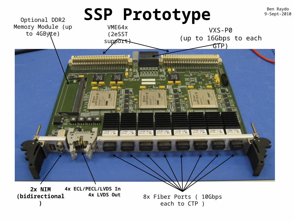
SSP PrototypeVME64x
(2eSST support)VXS-P0
(up to 16Gbps to each GTP)
Optional DDR2 Memory Module (up to 4GByte)
8x Fiber Ports ( 10Gbps each to CTP )2x NIM
(bidirectional)4x ECL/PECL/LVDS In
4x LVDS Out
Ben Raydo9-Sept-2010

GLOBAL TRIGGER PROCESSOR 1st Article Board
4 ChannelFiber
RJ45Ethernet
Jack
4x 8-ChannelLVPECL
Trigger Outputs to TS
Altera FPGAStratix IV GX
DDR2 Memory256 MB
Gigabit Links to SSPVXS “Switch” card
S. Kaneta2011

Discriminator Status(Not truly trigger system hardware, but very nice new development)
• 16 Pre-Production modules have been assembled and received
• Significantly cheaper than V895: -cost < $2,000
• Provides several features not found on V895:
- 32bit scalers on all channels at both thresholds
- Calibrated pulse widths: from 8 to 40ns- Trimmed input offset (<2mV error)- Second 34pin output connector is fully
programmable. - Able to perform logic based on all
channels at both thresholds
• Final revision has VME64x J1-J2 connector• Full test stand developed by Pedro
Toledo(USM – Chile) will be re-used• Hall Groups will test with detectors
Ben Raydo
16 modules in crate
Pre-Production versionNote: VME64x connectors

Synchronized Multi-Crate Readout• CTP #2 is also acting as an SSP (by summing the local crate + CTP#1 sum over fiber
• A programmable threshold is set in CTP, which creates a trigger when the global sum (6 FADC boards => 96 channels) is over threshold.
• Example test with a burst of 3 pulses into 16 channels across 2 crates/6 FADC modules
A 2μs global sum window is recorded around the trigger to see how the trigger was formed:
Example Raw Event Data for 1 FADC Channel:
B. Raydo

Input Signal to 16 FADC250 Channels:
Raw Mode Triggered Data (single channel shown only):
Global Sum Capture (at “SSP”):
• Runs at 250kHz in charge mode
• Latency: 2.3µs(measured) + 660ns(GTP estimate) < 3µs
2 Crate Energy Sum Testing
• Threshold applied to global sum (96 digitized channels) produces 3 triggers.
• Raw channel samples extracted from pipeline shown for 1 channel.
B. Raydo

Synchronized Multi-Crate Readout Rates
• FADC event synchronization has been stable for several billion events @ ~150kHz trigger rate.
• Have run up to 140kHz trigger rate in raw window mode, up to 170kHz in Pulse/Time mode.
• Ed Jastrzembski has completed the 2eSST VME Interface on FADC allowing ~200MB/s readout
B. Raydo
Single Crate12 signals distributedto four FADC250
18% Occupancy