gmcc access instructions for suppliers v7
TRANSCRIPT
FLEX N GATE GENERAL EQUIPMENT
SPECIFICATIONS
REV LEVEL: 18 DATE: March 16, 2014
REVISIONS NOTED IN BLUE
THE FOLLOWING INFORMATION IS PROPRIETARY TO FLEX N GATE. ANY REPRODUCTION
WITHOUT PRIOR WRITTEN CONSENT IS STRICTLY PROHIBITED.
GENERAL EQUIPMENT SPECIFICATIONS TABLE OF CONTENTS
INTRODUCTION ............................................................................................................................... 3 CHAPTER 1 – QUOTE INFORMATION REQUIRED ........................................................................ 4 CHAPTER 2 – TIMING / PROGRESS REPORTS ............................................................................. 5 CHAPTER 3 – QUALITY REQUIREMENTS ..................................................................................... 6 CHAPTER 4 – GENERAL STANDARDS .......................................................................................... 7 CHAPTER 5 – ERGONOMICS .......................................................................................................... 8 CHAPTER 6 – MECHANICAL DESIGN ............................................................................................ 9 CHAPTER 7 – ELECTRICAL DESIGN ........................................................................................... 11 CHAPTER 8 – RESISTANCE and MIG WELDING ......................................................................... 15 CHAPTER 9 – PNEUMATIC & COOLANT DESIGN ...................................................................... 18 CHAPTER 10 – HYDRAULIC DESIGN ........................................................................................... 20 CHAPTER 11 – ROBOT & SUPPORT EQUIPMENT DESIGN ....................................................... 21 CHAPTER 12 – OPERATOR & GENERAL SAFETY GUIDELINES .............................................. 22 CHAPTER 13 – PROGRAMMING, DIAGNOSTICS, & TROUBLESHOOTING .............................. 24 CHAPTER 14 – DRAWINGS, DIAGRAMS AND MANUFACTURERS MANUALS ........................ 26 CHAPTER 15 – PROJECT MANAGEMENT ................................................................................... 27 CHAPTER 16 (a) – MACHINE ACCEPTANCE – Vendor’s Shop Floor ........................................ 28 CHAPTER 16 (b) – MACHINE ACCEPTANCE – Flex N Gate’s Shop Floor ................................ 29 CHAPTER 17 – WARRANTY AND TRAINING ............................................................................... 30 CHAPTER 18 – PAYMENT TERMS & INVOICING ........................................................................ 31 APPENDIX ‘A’ ................................................................................................................................. 32
Machinery Standards Agreement ..................................................................................................... 32 APPENDIX ‘B’ ................................................................................................................................. 33
Flex N Gate Machinery Standards Deviation Approval .............................................................. 33 APPENDIX ‘C’ ................................................................................................................................. 34
Component Specifications ................................................................................................................. 34 APPENDIX ‘D’ ................................................................................................................................. 39
Mechanical Design Approval Form .................................................................................................. 39 APPENDIX ‘E’ ................................................................................................................................. 40
Electrical Design Approval Form ...................................................................................................... 40 APPENDIX ‘F’ ................................................................................................................................. 41
Receipt of Long Lead Items ............................................................................................................... 41 APPENDIX ‘G’ ................................................................................................................................. 42
Build Complete Approval Form ......................................................................................................... 42 APPENDIX ‘H’ ................................................................................................................................. 43
Approval to Ship Form ........................................................................................................................ 43 APPENDIX ‘I’ ................................................................................................................................... 44
Final Acceptance Form........................................................................................................................ 44 APPENDIX ‘J’ .................................................................................................................................. 45
Machine Dry Cycle Acceptance Form ............................................................................................. 45 APPENDIX ‘Z’ ................................................................................................................................. 46
Revision Log .......................................................................................................................................... 46
Flex N Gate MACHINERY STANDARDS - Rev 18 - 3-16-14 .doc
Page 2 of 46
INTRODUCTION
This rider describes the specifications and approval processes pertaining to the purchase of equipment by Flex N Gate.
Any deviation from the materials standards and specifications of this rider requires the prior written
approval of Flex N Gate Advanced Engineering Department. (See Appendix B)
1. All preliminary diagrams, drawings, and data must be formally approved by Flex N Gate
Advanced Engineering prior to commencement of project.
2. Acceptance of design by Flex N Gate does not in any way alleviate vendor from full
responsibility for the function, performance, and dependability of equipment being supplied.
Flex N Gate reserves the right to send engineering, operators, maintenance or any other authorized
representative to the vendor’s facility to evaluate progress at any stage of the project (i.e. build
stage, run-off stage, and machine acceptance stage).
Flex N Gate reserves the right to substitute components or parts in good working order of its own
choice and/or design at its own cost.
Flex N Gate MACHINERY STANDARDS - Rev 18 - 3-16-14 .doc
Page 3 of 46
CHAPTER 1 – QUOTE INFORMATION REQUIRED
1.1. The Flex N Gate Quote Summary must be completed and submitted with each quote prior to the machine being awarded.
1.2. The vendor quote must include the supply, design, fabrication, assembly, debug, and turnkey installation as required for a completely operational machine meeting all Flex N Gate supplied specifications.
1.3. Refer to Appendix ‘C’ for the list of components to use for quoting purposes (unless otherwise directed).
1.4. The quotation must include a complete breakdown of operations including, cycle times, number of operators, process flow, and machine capacity per hour (part to part basis).
1.5. Process layout to be provided in ACAD. Layout must portray an accurate concept of how the machine will function (including all material handling bins at each station.)
1.6. List of all robots including all required options. 1.7. Capital vs. Tooling Breakdown per station. 1.8. Vendor to include cost of shipping, and complete installation at Flex N Gate Facility in the
quote. 1.9. All plant details must be specified in quotes:
• Machine Size ( Length & Width) • Ceiling Height Requirements • Floor Requirements (i.e. Special footings, thickness, etc)
1.10 Programmable etching production run (date) stamp equipment to be quoted as optional equipment. (i.e. Telesis Technifor). This stamp must have the capabilities to mark the part number, engineering level, date, sequence number, and time on each part produced within the required cycle time.
1.11 Vendor/Builder to quote an optional line-side Computer and all related software (i.e. PLC, safety PLC, HMI, DeviceNet, ETC.) of the latest version, licensed to Flex N Gate.
1.12 A Marquis display must be quoted as an option. This display should indicate the production count, and if a fault occurs – it will display the station identification where the fault has occurred. The display characters are to be at a minimum of 4” characters and large enough to display all the necessary information.
1.13 All MIG welding to be processed using a welding speed of no greater than 25 IPM unless in the case of tandem welding.(or as otherwise directed by FNG Advanced Engineering).
Flex N Gate MACHINERY STANDARDS - Rev 18 - 3-16-14 .doc
Page 4 of 46
CHAPTER 2 – TIMING / PROGRESS REPORTS
2.1 Timing shall be discussed during the quoting stage and the vendor is expected to adhere to all timing requirements agreed on. A detailed timing schedule shall be issued with purchase order and will become an integral part of this specification.
2.2 The vendor is to issue progress reports at all main milestones indicated on the detailed timing schedule. Timing schedule is to be updated at a minimum bi-weekly during the project and sent via e-mail to the appropriate Flex N Gate personnel.
2.3 If the vendor falls behind the project timing they are expected to take all measures needed to get back on schedule, including, but not limited to increased manpower, overtime, weekend work, outsourcing, etc. All costs associated with maintaining the agreed project timing is the responsibility of the vendor.
Flex N Gate MACHINERY STANDARDS - Rev 18 - 3-16-14 .doc
Page 5 of 46
CHAPTER 3 – QUALITY REQUIREMENTS
3.1. The equipment must be process capable (minimum PP/PPK 1.67) of producing parts to
print. The key characteristics will be defined by Flex N Gate. 3.2. A report must be provided documenting all fixtures to be dimensionally certified prior to first
part produced. Each datum must be within 0.15mm of nominal. The final shims at each location should consist of 5mm loose and appropriate sized solid shim block (solid through-hole style only). EG. If 9.75mm of shim is required to set datum to nominal location, there should be 5mm of loose shim and a 4.75mm solid block.
3.3. Vendor is responsible to perform a 10 piece Tool Repeatability studies (static and dynamic) on all geo stations with the use of a portable CMM or Laser Tracker and provide reports. Any alternate method must be approved by Flex N Gate Personnel. Maximum range of each target must be less than 0.25mm. If the study fails, the problem must be documented with corrective actions, and the study re-run. This process must be repeated until it is successful.
3.4. All Part GD&T must be followed in the design of the machine unless approved in writing by authorized Flex N Gate personnel.
3.5. All Flex N Gate customer testing and validation requirements for all assemblies must be completed by the integrator. This testing must be performed at both the integrators shop floor and again at Flex N Gate after installation is complete. i.e. weld integrity testing, pull, push force testing, cut & etch, etc.
3.6. Integrator will be responsible to verify the weld integrity of all welds to ensure they meet or exceed Flex N Gate’s customer requirements. Weld integrity to be validated with a consecutive 10 piece capability study to be conducted on vendor’s shop floor. All welds must meet “set-up” requirements. If a discrepant weld is found the study must be restarted. This study must be completed for every path of every machine on every product. Welds are to be validated against the welding specifications supplied on the assembly print. In the case of spot welding, weld integrity to be verified via a destructive test method as per customer specification – no sonar testing allowed. In the case of projection welding, weld integrity must be verified via a destructive test utilizing the preferred customer method (push-out force or failure torque). In the case of MIG welding, cut-and-etch testing with microscope analysis and measurement to be performed on each weld. All weld integrity testing to be performed by the vendor. This test must be reconstructed on Flex N Gate’s floor after installation is complete. (Vendor to supply necessary equipment and personnel for both locations unless otherwise directed by FNG Advanced Engineering)
Flex N Gate MACHINERY STANDARDS - Rev 18 - 3-16-14 .doc
Page 6 of 46

CHAPTER 4 – GENERAL STANDARDS
4.1. This equipment must meet all safety requirements as required by the local authority
governing machine safety in the final plant destination.
4.2. All equipment must meet PSHSR (Pre Start-up Health & Safety Review) for all plants. It is the vendor’s responsibility to complete the safety review at the appropriate Flex N Gate plant(s) once the machine is installed at their cost. Integrator will be responsible to supply Flex N Gate a stamped PSHSR approval from a designated third party engineer, stating that the line has met all sections of the PSHSR requirements.
4.3. All Pneumatic piping on equipment being installed in a Canadian facility shall meet all TSSA standards requirements or equivalent.
4.4. Any deviation from the materials standards and specifications of this rider MUST have prior written approval of Flex N Gate Advanced Engineering Department.
4.5. All preliminary diagrams, drawings, and data must be formally approved by Flex N Gate Engineering prior to commencement of installation.
4.6. Any sub-contractors used in the manufacturing or design of the equipment must receive prior approval of Flex N Gate Engineering.
4.7. Builder must recognize any patent violations, be it Flex N Gate design or anyone else, and must notify Flex N Gate of possible violations immediately.
4.8. All equipment, both supplied and free issued, must be installed according to manufacturer’s recommendations. Failure to do so will result in the possible replacement of the equipment in question at the integrator’s expense. Documentation is required from each manufacturer which indicates that the equipment was installed and applied correctly. This documentation must be completed before the equipment is shipped to Flex N Gate and included in the witness book.
4.9. All machines which include dual path and / or dual geometry must have a unique identifying mark at each common station for lot traceability. The method of identification must be reviewed and approved by a Flex N Gate Engineer
4.10. All operator cycle times must be approved in writing by Flex N Gate. 4.11. The integrator must supply an accurate calculation of all service requirement (power, air,
water, cfm, etc) no later than the final design review. These calculations must include maximum as well as average values.
4.12. All equipment to be programmed and configured to maximize machine throughput, regardless of quoted cycle time. It is the integrators responsibility to ensure that all machine motions / sequences avoid excessive efficiency losses (i.e. excessive wait times, inefficient robot movements, sequence of operations, etc.)
Flex N Gate MACHINERY STANDARDS - Rev 18 - 3-16-14 .doc
Page 7 of 46
CHAPTER 5 – ERGONOMICS
5.1. Work height to be between 36” to 42” from floor. Work height is defined as the maximum height of the operators reach to load the machine.
5.2. All operator stations are to be designed to prevent motion behind the operator, and minimize part reaches (maximum 18”).
5.3. Consideration must be taken for component weight and size when designing fixtures, Heavier and larger components should be presented to and placed by the operator as close to their Front Body Center as possible.
5.4. Where people are interacting with the machine the required movements and grip forces shall remain within the safe ranges as established by ergonomic principles.
5.5. Personal fans must be installed at all manual stations. One personal fan per operator. 5.6. Operator is not to climb from floor level during cycle to cycle operation. 5.7. Automatic feeder hopper height must not exceed 48” from floor. 5.8. Where parts/assemblies are over 25 lbs in weight or are very bulky in nature, automatic load
and unload assist systems must be included. When stacked machine efficiencies may pose a problem in meeting annual volumes a power and free accumulating conveyor should be used.
Flex N Gate MACHINERY STANDARDS - Rev 18 - 3-16-14 .doc
Page 8 of 46
CHAPTER 6 – MECHANICAL DESIGN
6.1. Acceleration or deceleration of pneumatically or hydraulically controlled mechanisms shall be done with hydraulic shock absorbers or with a deceleration valve on hydraulic circuits. This is not necessary for any stroke less than 4” in either direction.
6.2. All steel guide ways shall have a hardened surface. 6.3. Pull pin dowels must be used. 6.4. All fasteners to be, at a minimum, installed with removable thread locking material (no thread locking
material permitted at shim locations), torque verified to the required specifications, and paint marked. 6.5. All fasteners must be grade 8 or better and no smaller than 6mm thread size. If a component being
installed does not allow for a 6mm thread size, integrator to use largest thread size possible without modifying component.
6.6. Any fasteners that are used for robot end effectors or subject to vibration must be wire-tied for security.
6.7. Setscrews (i.e. compressive force) shall not be used to secure part location pins in tooling. 6.8. Paint Code to be supplied in writing by Flex N Gate before painting begins. 6.9. All fixtures to be designed with 10mm NAAMS Standard shim packs that are interchangeable. The
design is to include a 5mm ground spacer and 5mm standard slot shim packs. When fixture certification is complete, each location should consist of 5mm loose and appropriate sized solid shim block. (e.g. If 9.75mm of shim is required to set datum to nominal location, there should be 5mm of loose shim and a 4.75mm solid block)
6.10. Spare shims equaling 5% of the overall shims used in the line must be provided upon machine delivery. All style of shims used must be included.
6.11. All fixture locating pins should have shimming in 2 directions (4 way & 2 way) 6.12. All back-up blocks and clamp fingers require shimming in the control direction. When blocks contact
an angled surface greater than 15 degrees, shimming is required in 2 directions. 6.13. All fixture locating pins must be hardened. 6.14. For metal assemblies, all back-up blocks and clamp fingers must be hardened and coated with black
oxide. 6.15. All clamping should be automatic, manual clamping should not be used without Flex N Gate
Engineering approval. All clamps should have the clamping arm doweled and bolted to the toggle body, not welded. All clamping cylinders to have flow controls on both ports mounted at the cylinder unless authorized by Flex N Gate. If parts are removed from the clamping station automatically, both open and closed status must be sensed for each clamp. If parts are manually removed, only the closed position of the clamps needs to be sensed unless the clamp open detection is required to prevent machine damage.
6.16. Mezzanine access should be via permanently attached stairs. All stairs and mezzanines to be certified and approved to meet all required safety codes.
6.17. Weld controls, water savers, bowl feeders, robot controllers, and any other devices needed for the normal operation of the machine will be situated outside of the machine guard area.
6.18. Components requiring regular maintenance or inspection, such as air cylinders, transformers, valves, weld gun shunts, lubricators, and relays, shall be readily accessible.
6.19. All components that are interfaced with any PLC I/O must be labeled. All labels should be mounted in such a fashion that if the device, hosing, wires, etc are removed, the label remains.
6.20. Lubrication points must be brought to a manifold no higher than eye level and easily accessible for proper lubrication maintenance. One manifold per station. Lube lines must be identified.
6.21. Equipment must have lift truck pockets for clearance. The fork clearances must be a minimum of 12" x 4” opening, 3' center to center of opening.
Flex N Gate MACHINERY STANDARDS - Rev 18 - 3-16-14 .doc
Page 9 of 46
6.22. All scrap from parts must be cleared from underside of equipment and away from areas of
mechanical moving parts. Scrap material shall not build up or interfere with production and will be easily accessible or automatically removed.
6.23. Machine wiring and plumbing routing must be included in the layout and approved by Flex N Gate before the work has begun.
6.24. Sensors must not be threaded into tooling. Tooling must have a clearance hole. 6.25. Automated part ejectors to be included in all stations where manual unloading of components is
required unless approved by Flex N Gate. 6.26. Parts must be positively retained during the entire transfer, load and work cycles. 6.27. Machine dampening and/or isolation shall be sufficient to permit operation at quoted speed and
tolerances without vibration. Vibration must not be transferred from station to station. 6.28. All fasteners must be accessible with standard hand tools without requiring the removal of adjacent
components / tooling. 6.29. When tooling requires change over, quick-change principles are required. Tooling connections to be
color coded and all positions, part styles, and options must be sensed. 6.30. Tooling to incorporate mistake proof principles. Tooling must be able to prevent incorrect part from
being loaded, or correct part loaded incorrectly. 6.31. Any special tools or equipment required to set-up or operate the machine must be supplied with the
machine. 6.32. All tooling slides/dumps must be verified with the use of sensors. These sensors must detect the
position of the tooling, not the actuator. These sensors must not be larger than 12mm in diameter in order to insure accurate position of the slide.
6.33. Integrator is responsible for small component staging around each operator load station. This is to include but not limited to bin trays, tote rollers, etc. The layout and container type must be reviewed and approved by the Flex N Gate end user plant.
Flex N Gate MACHINERY STANDARDS - Rev 18 - 3-16-14 .doc
Page 10 of 46
CHAPTER 7 – ELECTRICAL DESIGN 7.1. WIRING COLOR CODE
• Black -575 vac or 460 vac • Red -AC control or AC inputs / outputs • Blue -DC control or DC inputs • Yellow -Externally sourced voltage • White -Neutral • Green -Equipment Grounding Only (as per electrical standards)
7.2. All equipment and wiring shall meet the standards as required by the local authority
governing electrical safety in the final plant destination. Panels shall bear approval stickers as required by the local authority governing electrical safety in the final plant destination. Example: In Canada, all electrical equipment and wiring shall meet the code requirements of the Electrical Safety Authority, and all panels shall bear Electrical Safety Authority Approval stickers.
7.3. All 575 and 460 vac Wiring and control wiring must be run in a separate wireway or in a common wireway separated with a metal divider. All wireways must be raised off of the floor by a minimum of 3”. All wireways must be covered. Covers on the floor must be capable of supporting a person’s weight without deflection. Wireways must be sized to a maximum of 75% capacity. Cover must not contact cables.
7.4. All wires in wireways must pass directly from one wireway to the next without the wire being exposed. I.E. Cables exiting overhead cable tray must pass directly into covered wireway.
7.5. Wires must not exit the wireway more than 2 feet from the device which it is connected to. Wires must not be exposed from the point of origin to within 2 feet of the final point of use.
7.6. Every cell (mainline or sub-assembly) must have its own main electrical disconnect supplied by the integrator clearly labeled "MAIN DISCONNECT." The main disconnect should remove power from all electrically powered items in the machine except PLC power, lighting and service outlets. These should have a separate disconnect clearly labeled "MACHINE LIGHTING AND SERVICE DISCONNECT."
7.7. A UPS power supply must be included and wired to the PLC in the main line(s). The UPS must maintain power to the main PLC and Safety PLC during a power outage for a minimum of ½ hour.
7.8. Any push button box or enclosure must be NEMA 4 or better and should have a drain hole. 7.9. All wiring connections must meet a minimum rating of IP65 based on international IP Code. 7.10. Control transformers shall be mounted externally to all cabinetry containing electronic
equipment unless the cabinet is cooled. All transformers to be sized 25% larger than required for the machine to accommodate future expansion.
7.11. All sensing devices shall not have a supply voltage exceeding 24v ac/dc. It is the integrators responsibility to ensure all sensing devices are protected from damage from weld expulsion, impact, etc.
7.12. All single-phase transformers shall have grounded neutral if power from the transformer leaves the cabinet in which the transformer is installed.
Flex N Gate MACHINERY STANDARDS - Rev 18 - 3-16-14 .doc
Page 11 of 46
7.13. Wire identification shall be completed with Brady Style tags, which shall be oil and moisture
resistant. 7.14. Lighting with a dedicated on / off switch shall be installed by the integrator above all operator
stations. Lighting to be either T5 High Efficiency or LED. Machine lighting shall be no less than (40) foot-candles of light at work level. In the case of conveyor style assembly lines, overhead florescent lighting to be provided continuously above the entire conveyor perimeter. In the case of MIG welding cells with fume hoods covering plant lighting, the integrator is to install appropriate lighting within the cell.
7.15. Duplex receptacles capable of supplying 110 vac at 15 amps shall be mounted at each operation station. The power to these receptacles must remain when the main disconnect of the machine is disengaged. A maximum of four duplex receptacles per breaker. In the case of conveyor style assembly lines, receptacles are to be provided at 15-foot intervals along the perimeter of the line.
7.16. All operator interface panels should have external access to the program port. 7.17. The main control cabinet should have an internal 110 vac duplex. 7.18. All PLC control panels to be equipped with a line filter capable of noise filtering and voltage
limiting. 7.19. Control cabinets with heat generating devices (i.e. servo amplifier) must include an air
conditioning unit. 7.20. All conductors shall be copper, and the minimum gauge shall be #18. 7.21. One wire from each terminal, used on all limit switches, push buttons and other devices, shall
be returned to the main control panel or multi-port device block. All wires returned to the main control panel must be terminated to terminal strips. No series wiring of any devices is allowed unless written approval from Flex N Gate.
7.22. All field I/O devices must terminate to a multi-port block. 7.23. For each control panel, spare wires equal to 10% of the total in use, with a minimum of two,
shall be provided. 7.24. The main control panel for each machine shall have an ID Tag (oil and heat resistant, non-
fading, engraved black lettering on white background) with the following information: • Manufacturer:
o Date of Manufacture o Name o Address o Telephone number o Machine model # o Machine serial #
• Electrical o Volts (including Interrupting Capacity) o Amperage Phase o Cycles o Horse power (total of all motors)
• Air Pressure No other company advertising is allowed on the machine.
7.27. Flex N Gate customers require identification of tooling. Flex N Gate will supply the identification specifications / requirements to the integrator. It will be the integrators
Flex N Gate MACHINERY STANDARDS - Rev 18 - 3-16-14 .doc
Page 12 of 46
responsibility to apply the required identification to the equipment as identified by Flex N Gate prior to the shipment of the equipment. The integrator must log the identification information on the documentation provided by Flex N Gate.
7.28. All limit switches (relays, push buttons, fuse blocks, motors, etc.), solenoid valve coils and control actuators shall be provided with the oil and heat resistant, non-fading, engraved nameplates. Such nameplates shall contain black lettering on a white background, and the wording thereon shall be identical to the wording used on the elementary (schematic) diagram.
7.29. Spare terminals shall be provided on all control panels. The number of spare terminals shall be 10% of the total in use on each panel, subject to a minimum of 8 spare terminals for control conductors and 3 for power conductors. Multiple layers of terminal block arrangements will not be allowed.
7.30. All PLC control panels to have a minimum of 15% spare surface for future additions. 7.31. Operator Control Stations and Devices:
a. Shall utilize the following push button color code: Red (Mushroom Head) -Emergency stop White -Control Power ON Yellow (Mushroom Head) - Conveyor Stop (when independent of
Emergency Stop)
c. Shall be equipped with Palm Style Opto-Touch style cycle start button and used in conjunction with light curtains
d. Auto/Manual, Weld/No Weld, Step Forward, Cycle ready indicator, error messages, part counter, etc. must be active and displayed on the main screen of the Panel View
7.31. Fault finding panels shall be provided (HMI) at each operator station. Unless approved in writing by a Flex N Gate Advanced Engineer.
7.32. A disconnecting means shall be provided for all interlock control circuits energized from external sources.
7.33. For programmable controls, each input and output shall have a single dedicated terminal on the input and/or output board. Spare terminals equal to 10% of the total in use shall be provided on the I/O cards.
7.34. Any 600 or 460 volt distribution or fuse blocks within the panel must be supplied with a clear Lexan cover to prevent accidental contact with this block. 1/2” holes must be provided for required troubleshooting of wires and fuses.
7.35. Control enclosures and devices must be located so as to ensure adequate space is available for maintenance activity. Enclosure doors must be able to open a minimum of 120 degrees.
7.36. Small termination boxes must have ample room for termination of wires. At least 2” between any device or terminal and the side of the enclosure.
7.37. All motors shall have the following power supply characteristics:
120 / 575 Volts, 1 or 3 Phase 60 Hertz. (Canadian) 120 / 460 Volts, 1 or 3 Phase 60 Hertz (US)
Flex N Gate MACHINERY STANDARDS - Rev 18 - 3-16-14 .doc
Page 13 of 46
7.39. AC motors larger than 1/2HP, shall be 3 phase. 7.40. AC motors up to and including 100 HP, (1800 R.P.M.) shall be enclosed and fan-cooled
(except for motors smaller than frame size 184 which need not be fan cooled). 7.41. AC motors up to 30 HP shall be totally enclosed. Large DC motors shall be drip-proof
guarded with provision for external air pressurization. 7.42. Any AC motors that repeatedly start and stop (i.e. indexing conveyors) must be 3 phase. 7.43. The electrical system must meet the required interrupting capacity for the Flex N Gate
plant the machine is scheduled for. 7.44. For all Ethernet Networks an industrial rated line speed switch must be used. No Hubs
allowed. 7.45. The utility drops for each machine (power, air, water, etc.) must be located at a common
location along the guarding unless expressed written consent is provided by and authorized Flex N Gate Advanced Engineer.
7.46. All device net networks must be certified with the aid of a device net monitor and / or chart recorder before the machine leaves the integrator and again after the machine has been installed at Flex N Gate. A report must be supplied which documents the results.
7.47. All set-up files (i.e. device net EDS files) must be supplied with the machine. 7.48. All machines must have unique IP addresses so the equipment can be connected to plant
networks. Flex N Gate will provide the IP Address and Sub-net information. In the case of Ethernet/IP I/O networks, a network translation device (NAT) shall be provided to prevent IP Address conflicts.
7.49. All fiber optic cables shall be cut to appropriate length, secured and guarded against physical damage.
7.50. All fiber optic amplifiers shall be mounted together in a single bank in every stand alone machine or assembly line station. Each amplifier will be clearly labeled as to its function.
7.51. No Wire nut style connectors are to be used. If required, the use of crimp style may be used. 7.52. Machines / Equipment which test the electrical function of components to include electrical
test block connectors with spring detent pins. This is to ensure that the pins in the mating OEM connector are not damaged. Harting or similar style quick-connect fittings to be on electrical connector test blocks and electrical cabinet for quick-change. One spare junction cable with connectors, one spare electrical connector test block, and 30 spares of each style pin and sleeve to be supplied.
7.53. Each operator station to have a white ‘ALL PARTS PRESENT’ light on the load station / fixture. This light is to be visible to the operator during part loading. The light will flash once the first part is loaded and turn solid one all parts are detected.
7.54. Each operator station to have a green ‘OK TO ENTER’ light. This light is to be visible to the operator standing outside the light curtains. The light will be off when the station is loaded and the cycle initiated, solid when the equipment is ready for parts to be loaded, and flashing when the light curtain was violated after the cycle was initiated.
Flex N Gate MACHINERY STANDARDS - Rev 18 - 3-16-14 .doc
Page 14 of 46
CHAPTER 8 – RESISTANCE and MIG WELDING
8.1. All Spot welding to be quoted with Servo MFDC weld guns and tip dressers unless otherwise directed or approved by Flex N Gate.
8.2. Slow start electronic butterfly valves are required on the main water in and water return lines. The valves are to be activated (turn on water flow) at cycle start switch and deactivated (turn off main water flow) 2 minutes after last weld cycle.
8.3. Each Resistance Weld Guns must have:
• A Water Flow detection device which detect a water leak or missing weld cap. The device must be able to automatically stop the flow of water to the weld gun. The device must also be able to monitor water temperature and fault if the pre-set maximum temperature is exceeded.
• A flapper or gate type check valve after the flow switch. • Visible flow indicators for each flow path mounted on the weld gun (i.e.
transformers, upper electrode, lower electrode).
8.3. All shunts must be sized to protect against premature failure and must not make contact with moving components in the welder.
8.4. Use of equalizing or "Push-Pull" cylinders/welding system is not allowed. 8.5. Female caps are to be used wherever possible. Male caps allowed only with written
approval from Flex N Gate Engineering. 8.6. When using tip dressers, all guns must use Ball Nose caps. During weld cap change, tips
must be dressed prior to first weld. 8.7. Programming of weld controls:
Welding sequence parameters must not exceed:
• 75% max transformer current. • 60 cycles of passing current time. • Hold times no more than 10 cycles unless approved by Flex N Gate.
8.8. All weld controls must have programmed in the weld set-up the following fault conditions which will stop the machine cycle and indicate alarm (either externally or to a PLC).
• Hi-Lo current. These must be qualified with samples attaining appropriate weld nugget sizes.
• C-Factor • Power Factor Hi-Lo. • End of Stepper
Flex N Gate MACHINERY STANDARDS - Rev 18 - 3-16-14 .doc
Page 15 of 46
8.9. Pneumatic Weld cylinders/guns shall have a full open or returned detection where the index
of a cylinder/gun or tooling can cause damage if they remain in a closed position. 8.10. All Pneumatic Welding cylinders must have a gun close pressure switch with programmable
min / max pressure range for each unique tip pressure used.
8.11. Each machine must be supplied with a weld activity report including (Standard FNG format will be provided upon request);
• A graphical welding road map per station identifying customer weld number, gun number, station/robot number and weld sequence number
• Fully-Validated weld tip force setting both line pressure and resultant high pressure per weld for pneumatic weld guns.
• Fully-Validated weld schedule programs for each weld. • Identify all components that are assembled in the welder pertaining to weld
spots and specifications of nugget size requirements relating to a specification that appears on the assembly print.
• Fully-Validated servo pressure table set-up sheet
8.12. Return water header must be min 1/4" larger diameter than the incoming waterline. (Large applications to be determined with Flex N Gate Engineering.)
8.13. Weld caps must be accessible and free from obstruction with fixtures or any other part of the machine for tip change access.
8.14. "Tip Change" function must be programmed into equipment. The function must allow the selection of a global or individual change request. Once the function is enabled, the robot must move to a service position, the water valves automatically shut-off and the machine will stop. The technician will then change the required tips. Once the tip change is complete, the technician will select the tip change complete. The water will turn back on, “seat” the tips 3 times, the robots will tip dress (if equipped) and return to their safe position, and the associated steppers will be reset. The tip change screen on the panel view must show the completion of the cap change and the stepper reset validation.
8.15. All weld gun safety measures must be installed and operational. (i.e. over-temp switches for transformer).
8.16. For MIG welding, Vertical, Inverted, or Lateral welding is not permissible All welds must be completed in the horizontal welding position with “downhill” angle no more than 45 degrees.
8.17. Tooling fixture design must allow MIG welding torch access to welds at an angle equal to the perpendicular bisector of the angle created by the weld joints +/- 15 degrees (i.e. 90 degree fillet weld must be accessible at 45 degrees with clearance from 30-60 degrees)
8.18. Tooling design must allow torch clearance for a “push” or “pull” angle of +/- 15 degrees. Tooling design must consider the following “stick-out” conditions
.035” (0.9mm) weld wire – 10mm .045” (1.2mm) weld wire – 15mm .052” (1.4mm) weld wire – 17mm
8.20 Copper eat sinks to be added in situations as indicated by Flex N Gate. (i.e. extremely thin
materials with high burn-through potential).
Flex N Gate MACHINERY STANDARDS - Rev 18 - 3-16-14 .doc
Page 16 of 46

8.21 All MIG welding (steel) development to be completed using a 90/10 Ar/CO2 gas mix unless
otherwise dictated by Flex N Gate. 8.22 All MIG robots / operations must include individual gas flow meters and main gas distribution
manifold must include programmable gas pressure switches to ensure adequate gas pressure.
8.23 All nozzle reamers must include anti-spatter and automatic wire cutter. 8.24 All spatter-free zones must be protected with ampco bronze or copper spatter shields. 8.25 All MIG robots must have “TCP Check” routines and associated hardware. i.e. A TCP
reference pin must be attached to the machine and a routine must feed wire and cut to proper prescribed stickout length, and move to the pin for visual TCP confirmation.
8.26 PLC programming must include programmable MIG weld tip change screens and associated indicators. (The machine must indicate robot is due for weld tip change every “x” number of parts). The maximum number of parts per tip change to be adjustable through the operator interface. A tip change program must be included to move the robot to service position and after the tip change is acknowledged, the robots return to home position.
8.27 All Spot and MIG welds must have their own individual weld schedule for independent adjustment.
8.28 All weld schedules must be displayed in-line with robot programming code, not hidden in file numbers.
Flex N Gate MACHINERY STANDARDS - Rev 18 - 3-16-14 .doc
Page 17 of 46
CHAPTER 9 – PNEUMATIC & COOLANT DESIGN
9.1. No tape style sealant shall be used on threaded joints. 9.2. All air and water lines shall be identically labeled at both ends. 9.3. Cylinders and main movers must have adjustable flow controls on each port. 9.4. Filter regular (FR) units are to be supplied on main airline as required. Lubricators are to
be supplied as necessary (i.e. air motors). 9.5. A quick dump air valve to be supplied upstream of the FR unit, this must be of the locking
type. 9.6. Any grouping of actuators on a single valve must be approved by Flex N Gate prior to build.
If the actuators are clamps which are locating parts in the geometry stations, only clamps that are clamping in a common part direction may be grouped.
9.7. A regenerative desiccant air dryer is to be provided with all cells that require more than 100 CFM. The regenerative dryer must be controlled by dew point rather than time.
9.8. Piping should separate devices that require lubrication from devices that do not require lubrication, (i.e. Permanently lubricated cylinders).
9.9. All solenoid valves must be double solenoid except on drain valves or when used as a safety feature.
9.10. Piping shall have provision for installation of quick disconnect air couplings at each station. 9.11. All air and water lines shall have swivel fittings at both ends and shall be physically
protected from abrasion, expulsion, and spatter. 9.12. Flex N Gate will supply cooling water at 75 F +/- 5 where applicable. 9.13. A manual shut-off valve shall be installed on the bottom of all fluid tanks. 9.14. Quick disconnects must be provided for all fluid tanks for re-filling. Disconnects must be
located no higher that eye level and must be readily accessible. 9.15. Coolant flow rates through weld guns should be those recommended by the gun
manufacturer with an average supply differential of 30 psig provided at the drops. Guns should not be piped in series when there is a high duty cycle (i.e. Robots or fast cycle times). Each coolant circuit must be verified for flow at both the integrator and after the completion of installation at the appropriate Flex N Gate plant. The integrator must supply a report showing the required flow for each circuit and the actual flow.
9.16. All stations must have a water strainer and a shut-off valve on the cold water supply side and at a minimum, a check valve on the hot return.
9.17. Machines with water-cooled arc welding torches should have a water filter for arc welding torches.
9.18. All oil hoses from the AIR / OIL cylinder to be a minimum of 1/2". Air and water lines to be a minimum of 3/8".
9.19. All individual weld guns are to have a visual flow indicator on the return side of the manifold. This is to be plumbed in series with the guns - not in parallel and be visible to the operator.
9.20. All weld controllers must have a visual flow indicator on the water return line. 9.21. Pressure gauges are required on inlet and outlet of major hydraulic lines. 9.22. Drip line (min 24” long) at main air hook up is required to capture condensed air. Drip leg
must come complete with automatic dump valve.
Flex N Gate MACHINERY STANDARDS - Rev 18 - 3-16-14 .doc
Page 18 of 46

9.23. Check valve on water return must be lower than the lowest weld gun and mounted at each
station. 9.24. If cutting fluids are used, fluid must be recycled from a catch tray back into system. 9.25. All water line headers to be schedule 80 PVC pipe and all air headers to be black pipe.
Header tap off points to be hosing routed directly into and through cable tray to final point of use.
9.26. For the design of the pneumatic equipment, the vendor shall use 70 psig as the maximum available operating pressure.
9.27. Supply lines to the equipment shall be equipped with the necessary shut-off valves and filters. These devices shall be installed in an accessible location on the machine, not to exceed five feet above floor level.
9.28. Main pneumatic and water piping shall be run overhead of the line (header) on a slight angle to allow drainage at a single point. All tap off points are to be from the top of the manifold. Water return header must be larger than the water supply.
9.29. Each valve bank is to be equipped with its own filter. (lubricator if required). 9.30. All vertical motion tooling upon power down (e.g. E-Stop State) must be mechanically
locked to maintain position without drifting due to effects of gravity. This includes, but not limited to riveters, presses, and vertical shuttles. Methods of control to be decided during design review.
9.31. Any station with an Air Over Oil cylinder must be plumbed such that it only proceeds into high pressure after making an intermediate advance sensor. The sensor shall be positioned such that high pressure is only achieved if the parts are correctly mated.
9.32. Main water service to machine must include a pressure gauge at both the water in and water return lines to monitor water pressure differential. Main water service must also include water temperature gauges at both the water in and water return to manually monitor water temperature.
Flex N Gate MACHINERY STANDARDS - Rev 18 - 3-16-14 .doc
Page 19 of 46
CHAPTER 10 – HYDRAULIC DESIGN
10.1. Vendor will supply all fluid necessary to fill system. 10.2. Maximum hydraulic pressure on any flexible line shall be 1500 psi. Maximum hydraulic
pressure on rigid lines shall be 1800 psi. 10.3. Hydraulic pressure shall be dumped from accumulators upon shutdown. 10.4. Suction side of pump should be gravity feed and should have a valve installed in the suction
line of the pump with a sensor to ensure valve is open when pump is running. 10.5. Systems should have a hydraulic fluid temperature sensor to detect overheating of the
system. 10.6. Manual shut off valves should be installed at ground level on both pressure and return lines
when the hydraulic reservoir is on a mezzanine. Proximity switches should be installed to ensure all valves are open when pump is running.
10.7. System should have filters on both pressure and return lines. 10.8. Hydraulic power racks shall be located as close as possible to cylinders and valves in order
to eliminate trenches. 10.9. Power packs must be mounted on a drip tray, with valve drain. 10.10. Power packs must be designed with 50% excess capacity. 10.11. Power units may be water or air-cooled. To be specified during design stage.
Flex N Gate MACHINERY STANDARDS - Rev 18 - 3-16-14 .doc
Page 20 of 46
CHAPTER 11 – ROBOT & SUPPORT EQUIPMENT DESIGN
11.1. If any function of the robot control is necessary for the daily operation of the equipment, then those controls must be remote if the robot controller is mounted on a mezzanine or otherwise out of reach.
11.2. All controls for the robots will be placed in a position to allow service personnel to have access to the controls from the outside of the cell. The teach pendant will be accessible from outside the cell and able to be carried into the cell to the required robot.
11.3. Robot must be integrated according to manufactures specifications. It is the integrators responsibility to ensure that the robot manufacturer approves of the application and integration of the robot in writing prior to machine acceptance at the integrator’s shop floor.
11.4. Any motion errors during normal operation are unacceptable and must be corrected immediately. (i.e. torque errors, motion errors, etc).
11.5. An Emergency Stop push button shall be located inside the cell and wired to robot safety circuits.
Flex N Gate MACHINERY STANDARDS - Rev 18 - 3-16-14 .doc
Page 21 of 46
CHAPTER 12 – OPERATOR & GENERAL SAFETY GUIDELINES
12.1. All machines with transfers, index tables or other moving equipment must have adequate protection to prevent injury to operator from moving parts, arc flash or sparks during normal operation. All safety protection provided must meet the approval of the Ministry of Labor. (i.e., The Health and Safety Act) and IOSHA. Robotic Applications must comply with the most current Industrial Robots and Robot Systems General Safety Requirements. Acceptable means of operator protection to include the use of light curtains, palm button and general machine guarding.
12.2. Light curtains to be used to ensure operator safety on open style machine accesses, loading stations, indexing conveyors, rotary tables, etc. Light curtain installation must adhere to the current government standards for distance and size. All light curtains should be appropriately guarded from physical damage especially in cases where machine operators are loading and unloading parts.
12.3. Electrical safety door locks must be installed on all gate entry areas of the equipment. These devices must be energized to lock the door and unlock when power is removed.
12.4. Each safety door must have a device to allow for a personal lock-out lock or lock hasp. The permanent lock-out mechanism must be capable of attaching a minimum of 4 locks. This device must prevent the closure of the door when the lock is installed.
12.5. Each safety door is to be equipped with a push button panel that includes the maintenance key switch (keyed D020), a fault reset, and a piloted Request to Enter button. If the button is depressed, the pilot lights will begin to blink at each door. Once all motions are stopped and it is safe to enter, the pilot light will go solid and the doors will unlock. If the door is opened without the Maintenance Mode key switch in the ON position, all 24v power is removed from the stations. If the Maintenance mode key switch is selected before the Request to Enter button is depressed, it will stop all motions immediately (except for welds which are in process) and unlock the safety gates. If the Maintenance Mode key switch is ON, the 24v power is to remain on within the cell for manual motions only.
12.6. If the machine is equipped with a transfer mechanism, a warning buzzer should sound prior to initial transfer movement. The buzzer is to sound for five seconds before the motion begins and be at least 92db in volume.
12.7. Weld spark curtains should be provided for the perimeter of the machine to protect operator and other people working in the area. In arc welding applications, curtains should be dark enough to prevent arc flash and eye fatigue.
12.8. Machines with guns/tooling held up by electrical, pneumatic or hydraulic means should have an automatic mechanical method of locking tooling in position so that service can be completed with all power and air shut off with no subsequent tooling movement.
12.9. All emergency stop buttons on machines should be the maintain type so that an E-stop can only be released from the location where it is initiated. All remote manual stations should have an E-stop button on the panel.
12.10. Power on and automatic operation will be initiated from all operator stations. All remote manual stations should be able to turn the machine into auto or manual mode.
12.11. Machine cannot run in full automatic in "no weld" unless running in dry cycle. However, once a part is detected by a sensor, the dry cycle mode must automatically disable.
Flex N Gate MACHINERY STANDARDS - Rev 18 - 3-16-14 .doc
Page 22 of 46

12.12. Air must be dumped using a lockout type system. Air cannot remain trapped as potential
energy. 12.13. If spring force is required, equipment must have safeguards to prevent trapped energy from
moving the equipment in a "power off" condition. 12.14. Proper ventilation hoods must be included in the machine. The integrator is responsible to
cover the entire cell and provide one (1) connection point outside of the cell. Flex N Gate will be responsible to attach the single point to a fume extraction unit. If the hood used limits the amount of plant lighting into the cell, the integrator must provide lighting within the cell for maintenance. Local fume extraction is not permitted without the approved written consent of a Flex N Gate Advanced Engineer.
12.15. Equipment cannot transfer undue vibration to the operator.
Flex N Gate MACHINERY STANDARDS - Rev 18 - 3-16-14 .doc
Page 23 of 46
CHAPTER 13 – PROGRAMMING, DIAGNOSTICS, & TROUBLESHOOTING
13.1. Software generated diagnostics to have, as a minimum, indication of cycle status and input status programmed at the time of start up with provision for full diagnostics before completion of the machine.
13.2. Part counter for lot control is required on all machines. The part counter must be displayed on every screen on the panel view and when the reset is selected, a confirmation screen must be present.
13.3. All transfer or index style machines should have cycle run out capabilities either through the use of a selector switch, Panel View button, or part presence detector.
13.4. On machines equipped with light curtains, PLC to latch operator start button and unlatch should the light curtain be violated. This will allow operator to start next cycle before present cycle is completed giving operator ability to line up next set of parts etc.
13.5. If the machine has more than one operator Panel View, the error message will be displayed in detail at its station. All other stations will reference the faulted station.
13.6. If the machine stops, if the machine will not begin an automatic cycle, or a request manual motion does not proceed, the diagnostics should indicate why.
13.7. All machine motions must have a manual push button or function key through panel view, to control each motion. Manual mode must be highlighted on the panel view.
13.8. The overrides must be electrically or software interlocked to prevent mechanical damage to the machine in the event a wrong button is depressed.
13.9. All motions must be identified by an indicating light or reverse field on panel views when motion is complete.
13.10. Index tables must default to "slow speed" if indexed in manual modes unless written approval is given by the manufacturer of the index table in question.
13.11. All machine motions must be monitored by limit switches or sensors at each returned and advanced positions.
13.12. All machine motions must be safeguarded to protect components from mechanical damage due to malfunction of controls, cylinders, valves, etc. For example, a limit switch must sense that a slide motion has returned to a (safe) home position before a slide mechanism will be permitted to retract.
13.13. An auto cycle ready message must be displayed via Panel View. If a Panel View is not included in the machine, an auto cycle ready light must be provided at the operator station.
13.14. Part presence sensing must be used to ensure parts are correct, present and properly oriented in fixtures prior to any cycling of machines. These sensors must be protected from physical contact with components to prevent damage. The sensors must be indicated on control panel by lights or Panel Views. All off-line details presented to main line must be verified for part presence on final assembly. This includes all details on each sub-assembly. All sensors must look for both an ON & OFF condition. The machine should fault if the sensor is stuck on or off.
13.15. Any detail or sub-assembly loaded into a machine must also be verified for presence in the subsequent station.
13.16. All stations to have a ‘Reset to Home’ Push Button - via single push button used to sequence all motions to home position in a safe manner - for all stations within line. (Hardwired push button or HMI).
Flex N Gate MACHINERY STANDARDS - Rev 18 - 3-16-14 .doc
Page 24 of 46
13.17. All machines must include data acquisition logic. This logic must include a set-up screen
which allows adjustment of shift start/stop times, Break times, etc and a data screen. The data screen must show a cumulative quantity of occurrences and time of operator over cycles and faults for each station. The logic must exclude break times. The previous 2 shifts data must also be displayed on the screen. (Examples will be provided by Flex N Gate upon request).
13.18. Where analog inputs and outputs are used in PLC programming, the analog set-up parameters such as scaling, conversion, etc, as well as test machine default test limit settings will be set within the PLC program itself with the use if MOVE instructions.
13.19. All machines must have a screen which displays the current and last 10 cycle times of each station.
13.20. All operator interface panels must include screens in both English and the Flex N Gate plants native language. I.E. for Mexico, panel view screens must be displayed in English and Spanish.
13.21. It is the responsibility of the integrator to design and manufacture “red rabbit” parts. These parts should be constructed in a way such that the minimum # of parts or subassemblies can be loaded at once in order to test all part presence devices. These parts should be constructed utilizing the following principles: Nut detection w/Syron sensor or equivalent – remove/drill out nut Nut detection with a barrel or pancake prox – remove/grind down nut Stud detection – remove/grind down stud Detail stamping detection – cut away or drill out stamping in area where part is sensed. Construction/strategy of the red rabbit parts should be a collaborative effort between the integrator, FNG Advanced Mfg. Engineering, and end-user FNG plant. The actual construction of the parts is the responsibility of the integrator. Any deviations from this protocol must be approved in writing by FNG Advanced Mfg. Engineering.
13.22. “Red Rabbit” Sequence of Operation: The machine should automatically prompt the operator via a banner on the HMI screen at the beginning of each shift (shift times programmable) indicating that a red rabbit sequence is required. The operator should load the parts (may or may not require multiple-stage loads), and cycle start the machine. If all required conditions (sensors off) are met, parts are released and machine is allowed to enter automatic production mode. In the event of a failure, a descriptive fault banner should appear the failed sensor should be indicated on the HMI screen. The machine must not enter production mode until a successful red-rabbit sequence is executed. This may only be overridden by a key switch or supervisor password.
Flex N Gate MACHINERY STANDARDS - Rev 18 - 3-16-14 .doc
Page 25 of 46

CHAPTER 14 – DRAWINGS, DIAGRAMS AND MANUFACTURERS MANUALS
14.1. As built drawings are to be supplied within two weeks of machine approval. The following documentation shall be provided to Flex N Gate Engineering for the complete system:
1. Electrical Drawings – ACAD format 2. Mechanical Drawings – ACAD format for 2D & Native format for 3D 3. Pneumatic Drawings – ACAD format 4. Cooling System Drawings – ACAD format 5. Hydraulic Drawings – ACAD format 6. Accurate as-built machine layout – ACAD format 7. Complete and accurate bill of materials including part number, manufacturer,
distributor (including distributor contact information), price, and lead time. 8. List of recommended spare parts. 9. Consumable component drawings (i.e.; special
adaptors, punches, weld caps, etc.) 10. Mechanical assist drawings (transfers, lifts, shuttles, etc.) 11. All original equipment manufacturer’s literature (manuals and
data sheets). 12. Complete maintenance manuals including Preventative
Maintenance procedures 13. Set-up / Change over manuals complete with step by step
instructions, settings, photos, and diagrams.
14.2. Three copies of all items listed above on CD’s 14.3. One hard copy of all drawings and manuals (as listed above) in reproducible format.
(i.e. 3 ring binders) 14.4. Three copies on CD’s containing back-up programs for all PLCs, HMIs, Robots, etc. 14.5. Vendor shall, at least 6 weeks prior to delivery, provide Flex N Gate with a floor plan layout
displaying all electrical panels and main feed locations (electrical, pneumatic, & water) of the particular Flex N Gate plant services. Also to be included: power, water, pneumatic, and CFM requirements.
14.6. Witness book complete with all signed off forms and documents developed throughout the machine construction and installation.
Flex N Gate MACHINERY STANDARDS - Rev 18 - 3-16-14 .doc
Page 26 of 46
CHAPTER 15 – PROJECT MANAGEMENT
15.1. Vendor is responsible to coordinate and utilize all subcontractors or suppliers to ensure project is on schedule and problems are resolved as quickly as possible.
15.2. At a minimum Bi-weekly progress reports will be supplied to Flex N Gate. 15.3. An ongoing Process FMEA analysis is to be conducted by both parties to eliminate all
possible problems. 15.4. At project kickoff, vendor to supply/maintain master project timeline (Microsoft Project) and
Open Issues document. 15.5. Vendor responsible to maintain a detailed and current inventory of all FNG-supplied detail
stampings, fasteners, etc. as well as consumption of components inventory for machine development
15.6. Vendor must receive written approval from Flex N Gate to begin the various stages of the project. These stages are design, major component purchases, build of line, part development, disassembly and ship.
15.7. Flex N Gate must be notified in writing of any changes in delivery. If the change of delivery is unacceptable to Flex N Gate a corrective action plan must be developed and implemented to be able to meet scheduled delivery.
15.8. Any changes to the designs after they have been approved must be submitted in writing to Flex N Gate and approved.
15.9. Any changes to the timeline will not be allowed unless mutually approved in writing.
Flex N Gate MACHINERY STANDARDS - Rev 18 - 3-16-14 .doc
Page 27 of 46
CHAPTER 16 (a) – MACHINE ACCEPTANCE – Vendor’s Shop Floor
The following conditions must be satisfied prior to machine acceptance by Flex N Gate for each product to be produced.
16.1. Vendor to provide 12 hour dry-cycle at 100% of quoted cycle time on vendor shop floor. e.g. If the machine is quoted at 60 second cycle time, at the end of the 12 hours, the number of pieces must be a minimum of 720 pieces. If the machine stops for any reason, the process must be re-run. Appendix J must be completed for each dry cycle attempt whether successful or not. In the event the actual machine cycle time is under quoted cycle time, the run will be evaluated against actual cycle time.
16.2. Vendor is responsible to perform a 10 piece Tool Repeatability studies (static and dynamic) on geo stations and provide reports. Maximum range of each target must be less than 0.25mm. If the study fails, the problem must be documented with corrective actions, and the study re-run. This process must be repeated until it is successful.
16.3. Vendor to provide 1 hour of machine cycle of each part number at quoted rate (pcs/hr at 95% of quoted cycle time) e.g. Machine quoted at 60 second cycle time must meet an hourly rate of 57 pcs/hr. Any interruption that occurs more than once will constitute a failure and the run-off must be restarted. In the event the actual machine cycle time is under quoted cycle time, the run will be evaluated against actual cycle time The quantity can be reduced or waived on the vendors shop floor based on availability of supplied parts. IN THIS EVENT, THIS DOES NOT CONSTITUTE MACHINE ACCEPTANCE AT VENDOR'S FLOOR. FLEX N GATE'S MACHINE ACCEPTANCE WILL ONLY BE UPON SUCCESSFUL RUN-OFF OF EQUIPMENT AT FLEX N GATE'S SHOP FLOOR.
16.4. In the event that vendor cannot supply adequate utilities to satisfy machine acceptance on their shop floor, Flex N Gate will accept equipment to be shipped to Flex N Gate plant where these capability studies will be performed by the vendor at no cost to Flex N Gate. Flex N Gate will allow equipment to be shipped to Flex N Gate facility. IN THIS EVENT, THIS DOES NOT CONSTITUTE MACHINE ACCEPTANCE AT VENDOR'S FLOOR. FLEX N GATE'S MACHINE ACCEPTANCE WILL ONLY BE UPON SUCCESSFUL RUN-OFF OF EQUIPMENT AT FLEX N GATE'S SHOP FLOOR.
16.5. The vendor is responsible to keep a log of the interruption(s); the duration of the interruption(s) and the corrective action taken.
16.6. 10 consecutive piece weld destruct capability must be completed for all welds. Welds must meet the customer’s requirements. If a defective weld is found during the 10 pieces, corrections must be made and the study restarted.
16.7. A complete diagnostics review must be conducted. Every sensor must be tested for on/off conditions, identified on the operator interfaces and a fault message displayed.
16.8. All error-proof tooling and sensors must be verified station by station. 16.9. Vendor responsible to provide a 5-piece, full CMM layout for all assemblies produced at
vendor floor runoff. Measurement points will be supplied by FNG Engineering.
Flex N Gate MACHINERY STANDARDS - Rev 18 - 3-16-14 .doc
Page 28 of 46
CHAPTER 16 (b) – MACHINE ACCEPTANCE – Flex N Gate’s Shop Floor
16.10. Vendor to provide 3 hours of machine cycle or 300 pieces (whichever is more stringent) at quoted rate (pcs/hr at 95% of quoted cycle time) on Flex N Gate’s shop floor. e.g. Machine quoted at 60 second cycle time must meet an hourly rate of 57 pcs/hr. If the actual cycle time is lower than the quoted cycle time, run will be evaluated against actual cycle time. No adjustments or interruptions are permitted during this run. A significant interruption is defined as an interruption exceeding 5 minutes or one that occurs more than once for the same reason. The final one (1) hour is to be free from interruptions.
16.11. 30 pieces capability study, 6 Sigma capability PPK 1.67 on measurement points. These points to be confirmed by Flex N Gate Tool Engineering Department and conducted by vendor on Flex N Gate's floor. Flex N Gate will strive to achieve a PPK of 1.67 on each detail. If this is not possible the vendor will be responsible to at a minimum achieve a PP of 1.67 on all end item assemblies.
16.12. ACCEPTANCE MILESTONE AT FLEX N GATE IS AFTER A 2 WEEK PERIOD OF UNINTERRUPTED PRODUCTION ACHIEVING MACHINE DESIGNED CYCLE TIMES AND EFFICIENCIES. THE PLANT MANAGER WILL PROVIDE THE FINAL SIGNOFF.
16.13. A trained service engineer will supervise starting the equipment and instructing personnel after the installation is complete. This is to be without charge for a period agreed upon by vendor and Flex N Gate Engineering.
Machine acceptance and final payment will be processed once the user plant is satisfied with the quality and performance of the equipment and all open issues are completed to their satisfaction.
Flex N Gate MACHINERY STANDARDS - Rev 18 - 3-16-14 .doc
Page 29 of 46
CHAPTER 17 – WARRANTY AND TRAINING
WARRANTY
17.1. Flex N Gate recognizes the production launch date as the starting point for any warranted components or materials used in the manufacturing of the equipment. It is the vendor’s responsibility to negotiate this requirement for all materials purchased.
17.2. Any warranties provided by subcontractors or suppliers to the vendor shall be transferred to Flex N Gate.
17.3. Any shipping costs incurred because of failure of equipment or components will be for the account of the vendor.
17.4. Equipment shall be warranted against defects in material or workmanship for a period of 12 months from start of production.
TRAINING
17.5. Suppliers must provide sufficient training time to Flex N Gate personnel, including electricians, millwrights and operators, to ensure familiarity and understanding of the equipment installed. This is to be completed as follows after the machine has received final sign-off:
a. minimum of 2 days on vendor's shop floor b. minimum of 5 days start up, installation and debugging c. minimum 2 days after debugging for operator, maintenance training on Flex N Gate
shop floor.
17.6. Vendor must provide 2 man-days of training for Flex N Gate set-up and operating personnel. 17.7. All training must be documented at the time of training.
Flex N Gate MACHINERY STANDARDS - Rev 18 - 3-16-14 .doc
Page 30 of 46

CHAPTER 18 – PAYMENT TERMS & INVOICING
18.1 The following is Flex N Gate’s standard payment terms that, at a minimum, must be followed:
RECEIPT OF ALL MAJOR PURCHASES: 35% MACHINE BUILD COMPLETE: 25% APPROVAL TO SHIP: 20% FINAL ACCEPTANCE: 20%
All payment milestones are net 30 days from milestone sign-off and receipt of invoice.
18.2 All impacts (i.e. engineering changes) to the initial order are payable 100% at Final Acceptance, net 30.
18.3 The corresponding Milestone Sign-off forms (Appendix D-I) must accompany the invoice. An invoice must not be sent without the appropriate sign-off approval.
Flex N Gate MACHINERY STANDARDS - Rev 18 - 3-16-14 .doc
Page 31 of 46
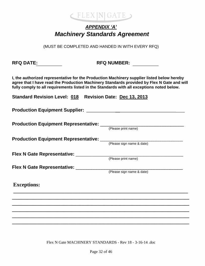
APPENDIX ‘A’
Machinery Standards Agreement
(MUST BE COMPLETED AND HANDED IN WITH EVERY RFQ) RFQ DATE: RFQ NUMBER: I, the authorized representative for the Production Machinery supplier listed below hereby agree that I have read the Production Machinery Standards provided by Flex N Gate and will fully comply to all requirements listed in the Standards with all exceptions noted below.
Standard Revision Level: 018 Revision Date: Dec 13, 2013
Production Equipment Supplier: __ ____ Production Equipment Representative: ________________________________
(Please print name)
Production Equipment Representative: _____________________________________ (Please sign name & date)
Flex N Gate Representative: ________________________________________________ (Please print name)
Flex N Gate Representative: _________________________________________ (Please sign name & date)
Exceptions: ___________________________________________________________________________________________________________________________________________________________________________________________________________________________________________________________________________________________________________________________________________________________________________________________________________
Flex N Gate MACHINERY STANDARDS - Rev 18 - 3-16-14 .doc
Page 32 of 46
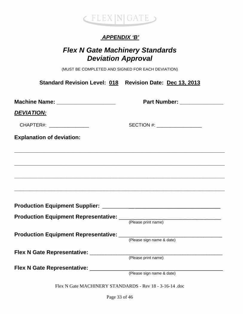
APPENDIX ‘B’
Flex N Gate Machinery Standards Deviation Approval
(MUST BE COMPLETED AND SIGNED FOR EACH DEVIATION)
Standard Revision Level: 018 Revision Date: Dec 13, 2013
Machine Name: ___________________ Part Number: ______________ DEVIATION:
CHAPTER#: _______________ SECTION #: _________________ Explanation of deviation:
____________________________________________________________________
____________________________________________________________________
____________________________________________________________________
____________________________________________________________________
Production Equipment Supplier: __ ________________________________ Production Equipment Representative: _________________________________
(Please print name)
Production Equipment Representative: _______________________________________ (Please sign name & date)
Flex N Gate Representative: __________________________________________________ (Please print name)
Flex N Gate Representative: ___________________________________________ (Please sign name & date)
Flex N Gate MACHINERY STANDARDS - Rev 18 - 3-16-14 .doc
Page 33 of 46
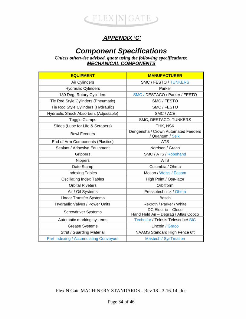
APPENDIX ‘C’
Component Specifications Unless otherwise advised, quote using the following specifications:
MECHANICAL COMPONENTS
EQUIPMENT MANUFACTURER Air Cylinders SMC / FESTO / TUNKERS
Hydraulic Cylinders Parker 180 Deg. Rotary Cylinders SMC / DESTACO / Parker / FESTO
Tie Rod Style Cylinders (Pneumatic) SMC / FESTO Tie Rod Style Cylinders (Hydraulic) SMC / FESTO
Hydraulic Shock Absorbers (Adjustable) SMC / ACE Toggle Clamps SMC, DESTACO, TUNKERS
Slides (Lube for Life & Scrapers) THK, NSK
Bowl Feeders Dengensha / Crown Automated Feeders / Quantum / Seiki
End of Arm Components (Plastics) ATS Sealant / Adhesive Equipment Nordson / Graco
Grippers SMC / ATS / Robohand Nippers ATS
Date Stamp Columbia / Ohma Indexing Tables Motion / Weiss / Easom
Oscillating Index Tables High Point / Osa-lator Orbital Riveters Orbitform Air / Oil Systems Pressotechnick / Ohma
Linear Transfer Systems Bosch Hydraulic Valves / Power Units Rexroth / Parker / White
Screwdriver Systems DC Electric – Cleco Hand Held Air – Degrag / Atlas Copco
Automatic marking systems Technifor / Telesis Telescribe/ SIC Grease Systems Lincoln / Graco
Strut / Guarding Material NAAMS Standard High Fence 6ft Part Indexing / Accumulating Conveyors Mastech / SysTmation
Flex N Gate MACHINERY STANDARDS - Rev 18 - 3-16-14 .doc
Page 34 of 46
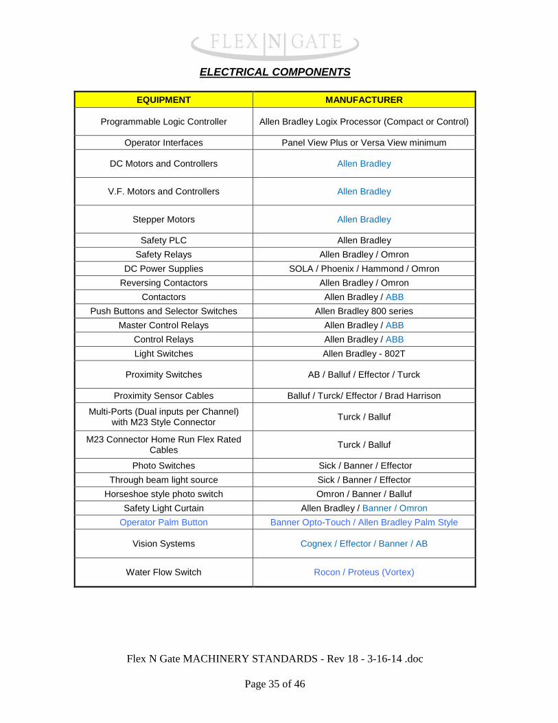
ELECTRICAL COMPONENTS
EQUIPMENT MANUFACTURER
Programmable Logic Controller Allen Bradley Logix Processor (Compact or Control)
Operator Interfaces Panel View Plus or Versa View minimum
DC Motors and Controllers Allen Bradley
V.F. Motors and Controllers Allen Bradley
Stepper Motors Allen Bradley
Safety PLC Allen Bradley Safety Relays Allen Bradley / Omron
DC Power Supplies SOLA / Phoenix / Hammond / Omron Reversing Contactors Allen Bradley / Omron
Contactors Allen Bradley / ABB Push Buttons and Selector Switches Allen Bradley 800 series
Master Control Relays Allen Bradley / ABB Control Relays Allen Bradley / ABB Light Switches Allen Bradley - 802T
Proximity Switches AB / Balluf / Effector / Turck
Proximity Sensor Cables Balluf / Turck/ Effector / Brad Harrison
Multi-Ports (Dual inputs per Channel) with M23 Style Connector Turck / Balluf
M23 Connector Home Run Flex Rated Cables Turck / Balluf
Photo Switches Sick / Banner / Effector Through beam light source Sick / Banner / Effector
Horseshoe style photo switch Omron / Banner / Balluf Safety Light Curtain Allen Bradley / Banner / Omron
Operator Palm Button Banner Opto-Touch / Allen Bradley Palm Style
Vision Systems Cognex / Effector / Banner / AB
Water Flow Switch Rocon / Proteus (Vortex)
Flex N Gate MACHINERY STANDARDS - Rev 18 - 3-16-14 .doc
Page 35 of 46
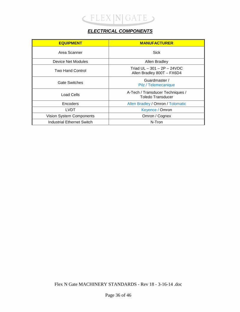
ELECTRICAL COMPONENTS
EQUIPMENT MANUFACTURER
Area Scanner Sick
Device Net Modules Allen Bradley
Two Hand Control Triad UL – 301 – 2P – 24VDC Allen Bradley 800T – FX6D4
Gate Switches Guardmaster / Pilz / Telemecanique
Load Cells A-Tech / Transducer Techniques / Toledo Transducer
Encoders Allen Bradley / Omron / Tolomatic LVDT Keyence / Omron
Vision System Components Omron / Cognex Industrial Ethernet Switch N-Tron
Flex N Gate MACHINERY STANDARDS - Rev 18 - 3-16-14 .doc
Page 36 of 46
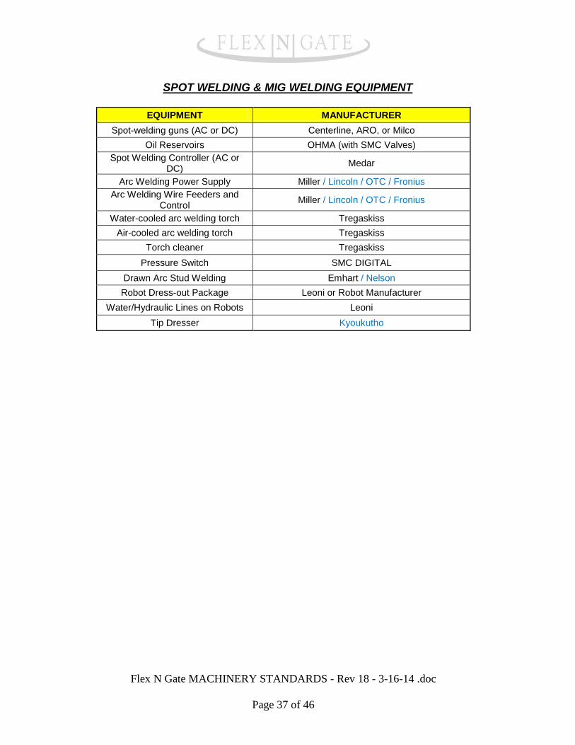
SPOT WELDING & MIG WELDING EQUIPMENT
EQUIPMENT MANUFACTURER Spot-welding guns (AC or DC) Centerline, ARO, or Milco
Oil Reservoirs OHMA (with SMC Valves) Spot Welding Controller (AC or
DC) Medar
Arc Welding Power Supply Miller / Lincoln / OTC / Fronius Arc Welding Wire Feeders and
Control Miller / Lincoln / OTC / Fronius
Water-cooled arc welding torch Tregaskiss Air-cooled arc welding torch Tregaskiss
Torch cleaner Tregaskiss Pressure Switch SMC DIGITAL
Drawn Arc Stud Welding Emhart / Nelson Robot Dress-out Package Leoni or Robot Manufacturer
Water/Hydraulic Lines on Robots Leoni Tip Dresser Kyoukutho
Flex N Gate MACHINERY STANDARDS - Rev 18 - 3-16-14 .doc
Page 37 of 46
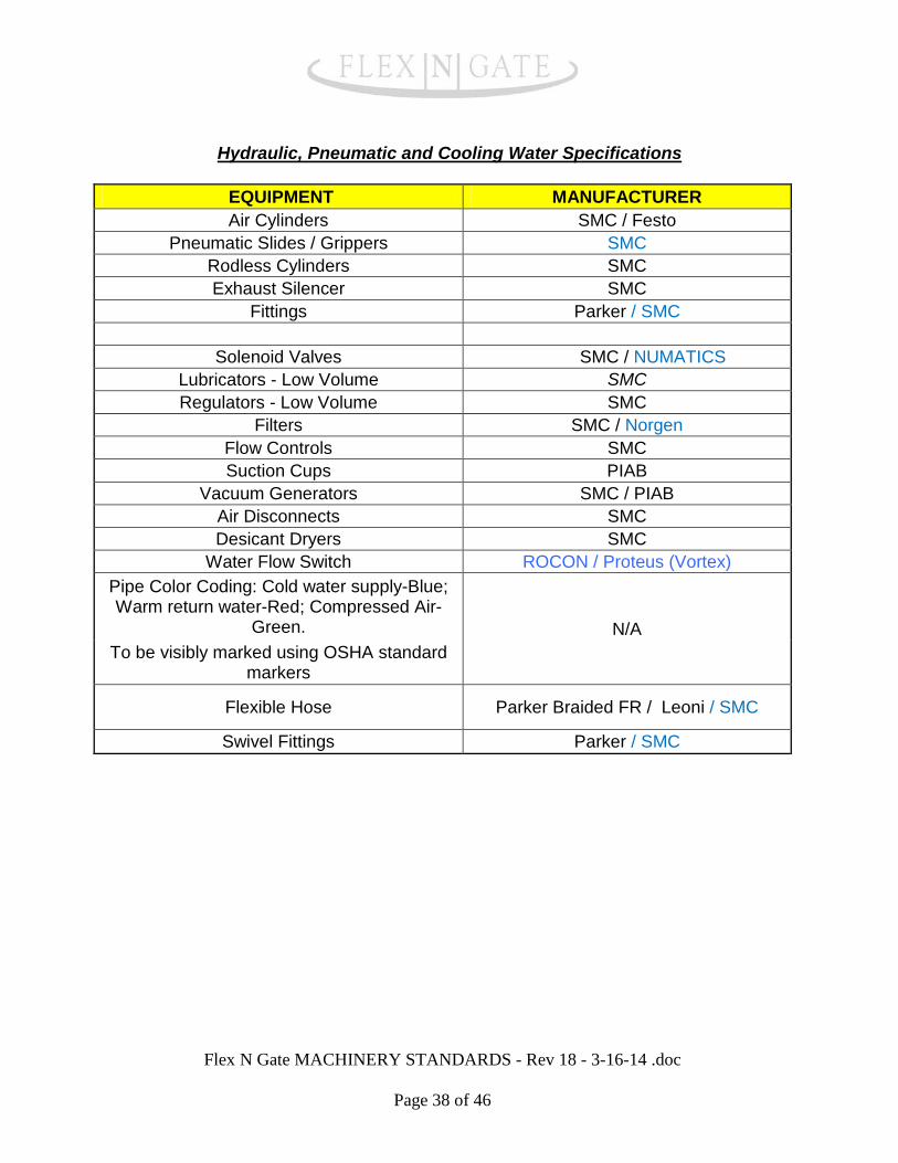
Hydraulic, Pneumatic and Cooling Water Specifications
EQUIPMENT MANUFACTURER Air Cylinders SMC / Festo
Pneumatic Slides / Grippers SMC Rodless Cylinders SMC Exhaust Silencer SMC
Fittings Parker / SMC
Solenoid Valves SMC / NUMATICS Lubricators - Low Volume SMC Regulators - Low Volume SMC
Filters SMC / Norgen Flow Controls SMC Suction Cups PIAB
Vacuum Generators SMC / PIAB Air Disconnects SMC Desicant Dryers SMC
Water Flow Switch ROCON / Proteus (Vortex) Pipe Color Coding: Cold water supply-Blue; Warm return water-Red; Compressed Air-
Green. N/A To be visibly marked using OSHA standard
markers
Flexible Hose Parker Braided FR / Leoni / SMC
Swivel Fittings Parker / SMC
Flex N Gate MACHINERY STANDARDS - Rev 18 - 3-16-14 .doc
Page 38 of 46
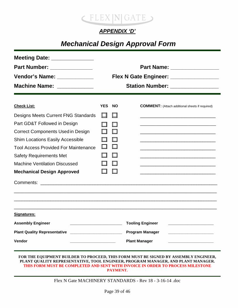
APPENDIX ‘D’
Mechanical Design Approval Form
Meeting Date: ______________ Part Number: ______________ Part Name: ________________ Vendor’s Name: ____________ Flex N Gate Engineer: ________________ Machine Name: ____________ Station Number: ________________
Check List: YES NO COMMENT: (Attach additional sheets if required) Designs Meets Current FNG Standards _____________________________
Part GD&T Followed in Design ___________________________________
Correct Components Used in Design _____________________________
Shim Locations Easily Accessible _____________________________
Tool Access Provided For Maintenance _____________________________
Safety Requirements Met _____________________________
Machine Ventilation Discussed _____________________________
Mechanical Design Approved _____________________________
Comments: ____________________________________________________________________
______________________________________________________________________________
______________________________________________________________________________
______________________________________________________________________________ Signatures: Assembly Engineer ________________________ Tooling Engineer _____________________
Plant Quality Representative ________________________ Program Manager _____________________
Vendor _____________________ Plant Manager _____________________
FOR THE EQUIPMENT BUILDER TO PROCEED, THIS FORM MUST BE SIGNED BY ASSEMBLY ENGINEER, PLANT QUALITY REPRESENTATIVE, TOOL ENGINEER, PROGRAM MANAGER, AND PLANT MANAGER.
THIS FORM MUST BE COMPLETED AND SENT WITH INVOICE IN ORDER TO PROCESS MILESTONE PAYMENT.
Flex N Gate MACHINERY STANDARDS - Rev 18 - 3-16-14 .doc
Page 39 of 46
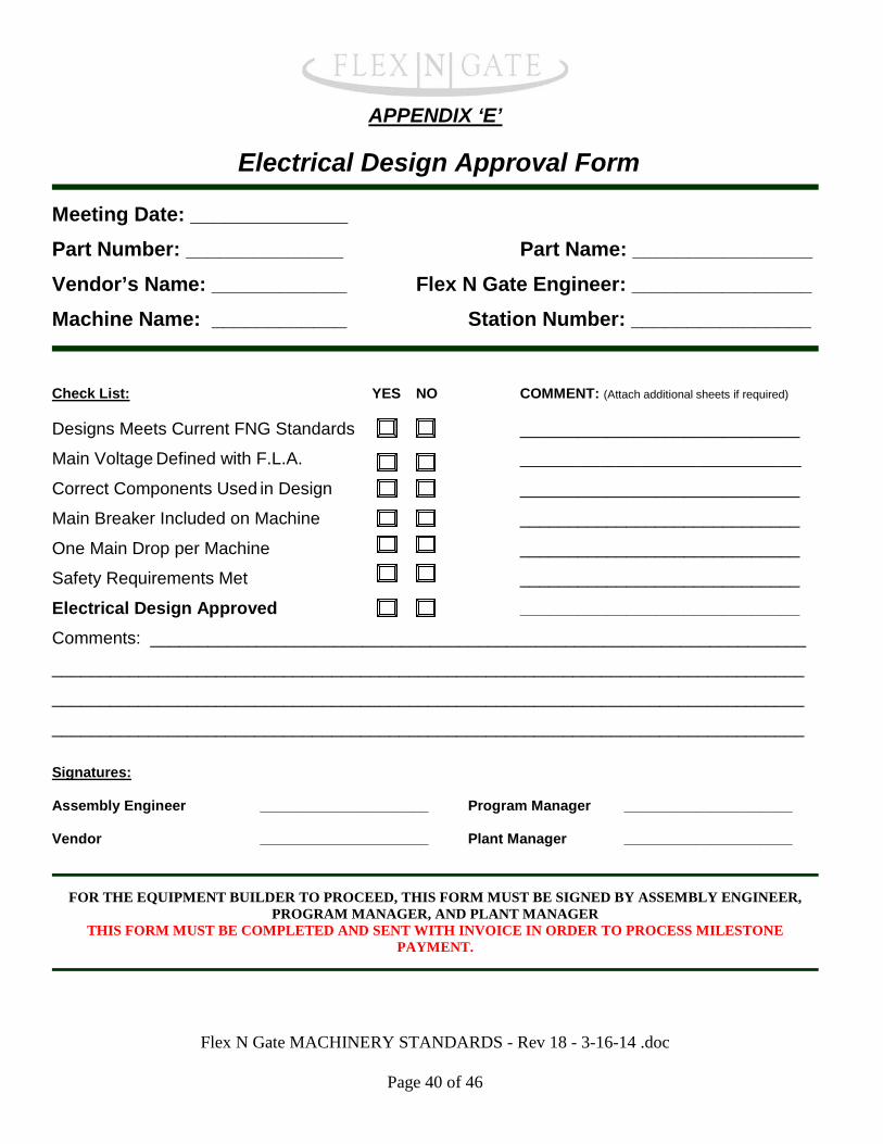
APPENDIX ‘E’
Electrical Design Approval Form
Meeting Date: ______________ Part Number: ______________ Part Name: ________________ Vendor’s Name: ____________ Flex N Gate Engineer: ________________ Machine Name: ____________ Station Number: ________________
Check List: YES NO COMMENT: (Attach additional sheets if required) Designs Meets Current FNG Standards _____________________________
Main Voltage Defined with F.L.A. ___________________________________
Correct Components Used in Design _____________________________
Main Breaker Included on Machine _____________________________
One Main Drop per Machine _____________________________
Safety Requirements Met _____________________________
Electrical Design Approved _____________________________ Comments: ____________________________________________________________________
______________________________________________________________________________
______________________________________________________________________________
______________________________________________________________________________ Signatures: Assembly Engineer _____________________ Program Manager _____________________
Vendor _____________________ Plant Manager _____________________
FOR THE EQUIPMENT BUILDER TO PROCEED, THIS FORM MUST BE SIGNED BY ASSEMBLY ENGINEER,
PROGRAM MANAGER, AND PLANT MANAGER THIS FORM MUST BE COMPLETED AND SENT WITH INVOICE IN ORDER TO PROCESS MILESTONE
PAYMENT.
Flex N Gate MACHINERY STANDARDS - Rev 18 - 3-16-14 .doc
Page 40 of 46
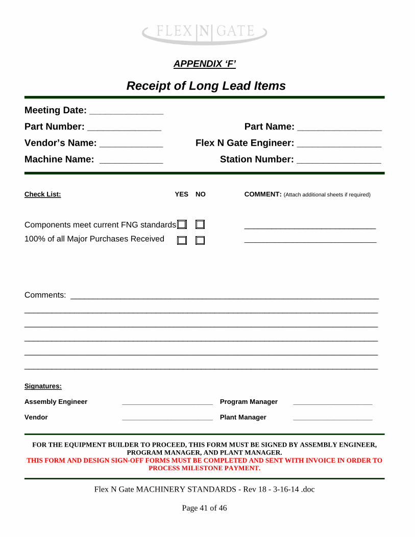
APPENDIX ‘F’
Receipt of Long Lead Items
Meeting Date: ______________ Part Number: ______________ Part Name: ________________ Vendor’s Name: ____________ Flex N Gate Engineer: ________________ Machine Name: ____________ Station Number: ________________
Check List: YES NO COMMENT: (Attach additional sheets if required)
Components meet current FNG standards _____________________________
100% of all Major Purchases Received ___________________________________
Comments: ____________________________________________________________________
______________________________________________________________________________
______________________________________________________________________________
______________________________________________________________________________
______________________________________________________________________________
______________________________________________________________________________ Signatures: Assembly Engineer ________________________ Program Manager _____________________
Vendor ________________________ Plant Manager _____________________
FOR THE EQUIPMENT BUILDER TO PROCEED, THIS FORM MUST BE SIGNED BY ASSEMBLY ENGINEER,
PROGRAM MANAGER, AND PLANT MANAGER. THIS FORM AND DESIGN SIGN-OFF FORMS MUST BE COMPLETED AND SENT WITH INVOICE IN ORDER TO
PROCESS MILESTONE PAYMENT.
Flex N Gate MACHINERY STANDARDS - Rev 18 - 3-16-14 .doc
Page 41 of 46

APPENDIX ‘G’
Build Complete Approval Form
Meeting Date: ______________ Part Number: ______________ Part Name: ________________ Vendor’s Name: ____________ Flex N Gate Engineer: ________________ Machine Name: ____________ Station Number: ________________
Check List: YES NO COMMENT: (Attach additional sheets if required) Build Meets Current FNG Standards _____________________________
Machine Built as Per Design ___________________________________
Mechanical Build Complete _____________________________
Electrical Build Complete _____________________________
Pneumatic Build Complete _____________________________
Cable and Hose Routing Acceptable _____________________________
Safety Requirements Met _____________________________
Build Complete Approved _____________________________
Comments: ____________________________________________________________________
______________________________________________________________________________
______________________________________________________________________________ Signatures: Assembly Engineer ________________________ Program Manager _____________________
FNG Plant Representative ________________________ Vendor _____________________
Plant Manager ________________________
FOR THE EQUIPMENT BUILDER TO PROCEED, THIS FORM MUST BE SIGNED BY ASSEMBLY ENGINEER, PROGRAM MANAGER, AND PLANT MANAGER.
THIS FORM MUST BE COMPLETED AND SENT WITH INVOICE IN ORDER TO PROCESS MILESTONE PAYMENT.
Flex N Gate MACHINERY STANDARDS - Rev 18 - 3-16-14 .doc
Page 42 of 46
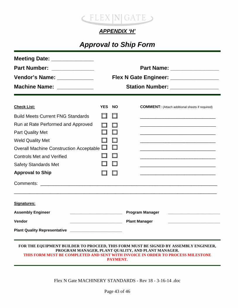
APPENDIX ‘H’
Approval to Ship Form
Meeting Date: ______________ Part Number: ______________ Part Name: ________________ Vendor’s Name: ____________ Flex N Gate Engineer: ________________ Machine Name: ____________ Station Number: ________________
Check List: YES NO COMMENT: (Attach additional sheets if required) Build Meets Current FNG Standards _____________________________
Run at Rate Performed and Approved ___________________________________
Part Quality Met _____________________________
Weld Quality Met _____________________________
Overall Machine Construction Acceptable _____________________________
Controls Met and Verified _____________________________
Safety Standards Met _____________________________
Approval to Ship _____________________________
Comments: ____________________________________________________________________
______________________________________________________________________________ Signatures: Assembly Engineer ________________________ Program Manager ________________________
Vendor ________________________ Plant Manager ________________________
Plant Quality Representative ________________________
FOR THE EQUIPMENT BUILDER TO PROCEED, THIS FORM MUST BE SIGNED BY ASSEMBLY ENGINEER,
PROGRAM MANAGER, PLANT QUALITY, AND PLANT MANAGER. THIS FORM MUST BE COMPLETED AND SENT WITH INVOICE IN ORDER TO PROCESS MILESTONE
PAYMENT.
Flex N Gate MACHINERY STANDARDS - Rev 18 - 3-16-14 .doc
Page 43 of 46

APPENDIX ‘I’
Final Acceptance Form
Meeting Date: ______________ Part Number: ______________ Part Name: ________________ Vendor’s Name: ____________ Flex N Gate Engineer: ________________ Machine Name: ____________ Station Number: ________________
Check List: YES NO COMMENT: (Attach additional sheets if required) Build Meets Current FNG Standards _____________________________
Run at Rate Performed and Approved ___________________________________
Part Quality Met _____________________________
Weld Quality Met _____________________________
Overall Machine Construction Acceptable _____________________________
Controls Met and Verified _____________________________
Safety Standards Met _____________________________
Machine Accepted _____________________________
Comments: ____________________________________________________________________
______________________________________________________________________________ Signatures: Assembly Engineer ________________________ Program Manager _____________________
Plant Quality Representative ________________________ Vendor _____________________
Director of Adv. Programs ________________________ Plant Manager ______________________
FOR FINAL ACCEPTANCE, THIS FORM MUST BE SIGNED BY ASSEMBLY ENGINEER, PLANT QUALITY,
PROGRAM MANAGER, AND PLANT MANAGER. THIS FORM MUST BE COMPLETED AND SENT WITH INVOICE IN ORDER TO PROCESS MILESTONE
PAYMENT.
Flex N Gate MACHINERY STANDARDS - Rev 18 - 3-16-14 .doc
Page 44 of 46

APPENDIX ‘J’
Machine Dry Cycle Acceptance Form
Date of Dry Cycle Run: ______________ Part Number: ______________ Part Name: ________________ Vendor’s Name: ____________ Flex N Gate Engineer: ________________ Machine Name: ____________ Station Number: ________________
Check List: Start Time of Dry Cycle : _____________ End of Dry Cycle :
Quoted Machine JPH : _____________ Quoted Cycle Time :
Total cycles required to be run (JPH x 12 hours) : _____________
Total cycles actually run (from part counter) : ________________
Dry Cycle Run Accepted Yes No
If No, list reason(s) for failure : _____________________________
Comments :
Signatures: Assembly Engineer Program Mgr
Plant Representative Vendor
Plant Manager
FOR THE EQUIPMENT BUILDER TO PROCEED, THIS FORM MUST BE SIGNED BY ASSEMBLY ENGINEER,
PROGRAM MANAGER, PLANT REPRESENTATIVE, AND PLANT MANAGER. THIS FORM MUST BE COMPLETED AND SENT WITH INVOICE IN ORDER TO PROCESS MILESTONE
PAYMENT.
Flex N Gate MACHINERY STANDARDS - Rev 18 - 3-16-14 .doc
Page 45 of 46
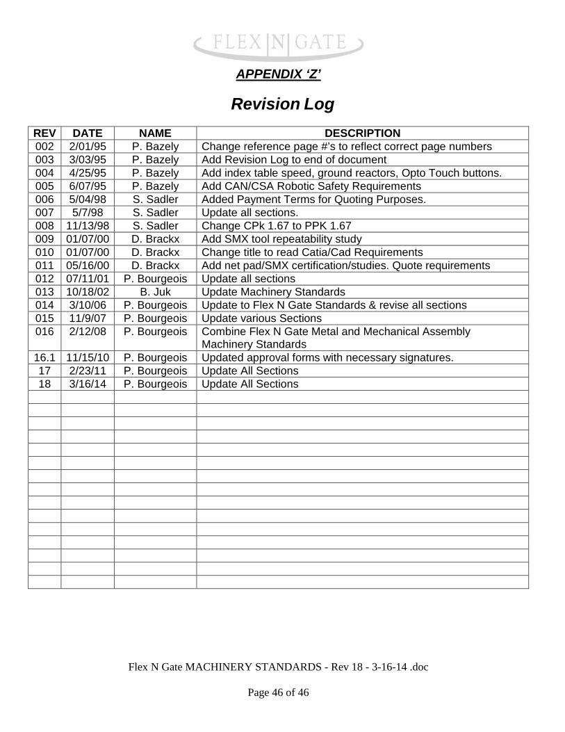
APPENDIX ‘Z’
Revision Log REV DATE NAME DESCRIPTION 002 2/01/95 P. Bazely Change reference page #’s to reflect correct page numbers 003 3/03/95 P. Bazely Add Revision Log to end of document 004 4/25/95 P. Bazely Add index table speed, ground reactors, Opto Touch buttons. 005 6/07/95 P. Bazely Add CAN/CSA Robotic Safety Requirements 006 5/04/98 S. Sadler Added Payment Terms for Quoting Purposes. 007 5/7/98 S. Sadler Update all sections. 008 11/13/98 S. Sadler Change CPk 1.67 to PPK 1.67 009 01/07/00 D. Brackx Add SMX tool repeatability study 010 01/07/00 D. Brackx Change title to read Catia/Cad Requirements 011 05/16/00 D. Brackx Add net pad/SMX certification/studies. Quote requirements 012 07/11/01 P. Bourgeois Update all sections 013 10/18/02 B. Juk Update Machinery Standards 014 3/10/06 P. Bourgeois Update to Flex N Gate Standards & revise all sections 015 11/9/07 P. Bourgeois Update various Sections 016 2/12/08 P. Bourgeois Combine Flex N Gate Metal and Mechanical Assembly
Machinery Standards 16.1 11/15/10 P. Bourgeois Updated approval forms with necessary signatures. 17 2/23/11 P. Bourgeois Update All Sections 18 3/16/14 P. Bourgeois Update All Sections
Flex N Gate MACHINERY STANDARDS - Rev 18 - 3-16-14 .doc
Page 46 of 46