gmch building 10 remedial investigation work plan components holdings, llc 200 upper mountain road...
TRANSCRIPT
GM COMPONENTS HOLDINGS, LLC 200 UPPER MOUNTAIN ROAD LOCKPORT, NEW YORK BUILDING 10 SITE # 932140 REMEDIAL INVESTIGATION WORK PLAN
PREPARED FOR: New York State Department of Environmental Conservation PREPARED BY: GZA GeoEnvironmental of New York Buffalo, New York June 2010 File No. 21.0056546.00
i 6/16/2010
GM COMPONENTS HOLDINGS, LLC LOCKPORT, NEW YORK
BUILDING 10 SITE ID #C932140 BROWNFIELD CLEANUP PROGRAM
REMEDIAL INVESTIGATION WORK PLAN TABLE OF CONTENTS
Page
1.0 INTRODUCTION ....................................................................................................... 1
1.1 PURPOSE ................................................................................................................. 1 1.2 PROPERTY DESCRIPTION ................................................................................... 1 1.3 BACKGROUND ...................................................................................................... 2 1.4 INVESTIGATION OBJECTIVES ........................................................................... 4
2.0 DESCRIPTION OF FIELD ACTIVITIES .................................................................. 5
2.1 GENERAL FIELD ACTIVITIES ............................................................................. 5 2.1.1 Site Meetings ......................................................................................................... 5 2.1.2 Mobilization .......................................................................................................... 5 2.1.3 Health and Safety .................................................................................................. 5 2.1.4 Decontamination and Handling of Investigation Derived Waste .......................... 5 2.1.5 Survey .................................................................................................................... 6
2.2 RI FIELD INVESTIGATIONS ................................................................................ 6 2.2.1 Soil Probes ............................................................................................................. 6 2.2.2 Test Boring, Monitoring Well Installation and Sampling ...................................... 7 2.2.3 Indoor Air Sampling ............................................................................................... 9 2.2.3 Fish and Wildlife Resources Impact Analysis ....................................................... 9
2.3 ENVIRONMENTAL ANALYTICAL TESTING PROGRAM ............................. 10 2.4 SURVEY ................................................................................................................ 10
3.0 ADDITIONAL FIELD EXPLORATIONS .............................................................. 10
4.0 QUALITY ASSURANCE/QUALITY CONTROL ................................................. 11
5.0 HEALTH AND SAFETY PROTOCOLS ................................................................. 11
6.0 SCHEDULE .............................................................................................................. 11
7.0 CITIZEN PARTICIPATION .................................................................................... 12
ii 6/16/2010
TABLE OF CONTENTS (CONT’D)
TABLES TABLE 1 PROPOSED ANALYTICAL SAMPLING PROGRAM FIGURES FIGURE 1 LOCUS PLAN FIGURE 2 SITE PLAN FIGURE 3 PREVIOUSLY INDENTIFED AREAS OF INTEREST FIGURE 4 FOCUSED ENVIRONMENTAL ASSESSMENT FIGURE FIGURE 5 SVE/SSD SYSTEM LAYOUT FIGURE 6 BROWNFIELD CLEANUP PROGRAM SITES & SITE WIDE
INVESTIGATION FIGURE FIGURE 7 PROPOSED EXPLORATION LOCATION PLAN APPENDICES APPENDIX A FIELD METHOD GUIDELINES for: Equipment Decontamination Waste Characterization Soil Boring Soil Classification Bedrock Coring
Rock Classification Well Construction Materials
Deep Bedrock Wells Soil Sampling Well Development In-Situ Hydraulic Conductivity (Slug Test) Procedure Water Level Measurements Groundwater Sampling Sample Handling & Shipping

1 6/16/2010
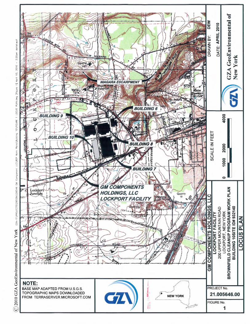
1.0 INTRODUCTION 1.1 PURPOSE The purpose of this Remedial Investigation Work Plan (RIWP) is to describe activities planned for the implementation of the Remedial Investigation (RI) associated with Building 10 (Site ID # C932140) at the GM Components Holdings, LLC (GMCH) Lockport Facility, located at 200 Upper Mountain Road, in the City of Lockport, New York (see Figure 1). The work described in this RIWP is being done under a New York State Department of Environmental Conservation (NYSDEC) Brownfield Cleanup Program (BCP) Agreement. GZA GeoEnvironmental of New York (GZA) will be responsible for completing the RI for Building 10. It should be noted that there are three separate BCP Sites associated with the GMCH Lockport Facility, as follows.
• GM Components Holdings, LLC Building 7, site ID #C932138 (Building 7) • GM Components Holdings, LLC Building 8, site ID #C932139 (Building 8) • GM Components Holdings, LLC Building 10, site ID #C932140 (Building 10)
This RIWP has been developed for the work associated with Building 10. Separate RIWPs have been developed for the work associated with Building 7 and Building 8. 1.2 PROPERTY DESCRIPTION The GMCH facility is located at 200 Upper Mountain Road in both the City and Town of Lockport, which is located in Niagara County, New York. The portion of the facility which includes Building 10 is located within the City of Lockport. The GMCH facility is approximately 342 acres in size and located in an area of mixed residential, agricultural, commercial, and industrial settings along Upper Mountain Road. Building 10 constitutes approximately 11 of the 342 acres and is located in the southern central portion of the GMCH facility. Across Upper Mountain Road, the Niagara Escarpment is located approximately one-half mile to the northeast. A stone quarry and former steel facility are located approximately 1 mile south of GMCH. Residential properties are generally present along the east and north sides of Upper Mountain Road and to the west. Within the facility, Building 7, Building 8 and Building 9 are dedicated to manufacturing and engineering. Building 10 has been converted to house new manufacturing operations staffed by non-GMCH personnel in the northern portion with the southern portion being used by GMCH as a warehouse. Building 6 has been leased to Delphi Properties Management, LLC for vehicle component engineering and testing (see Figure 2).

2 6/16/2010
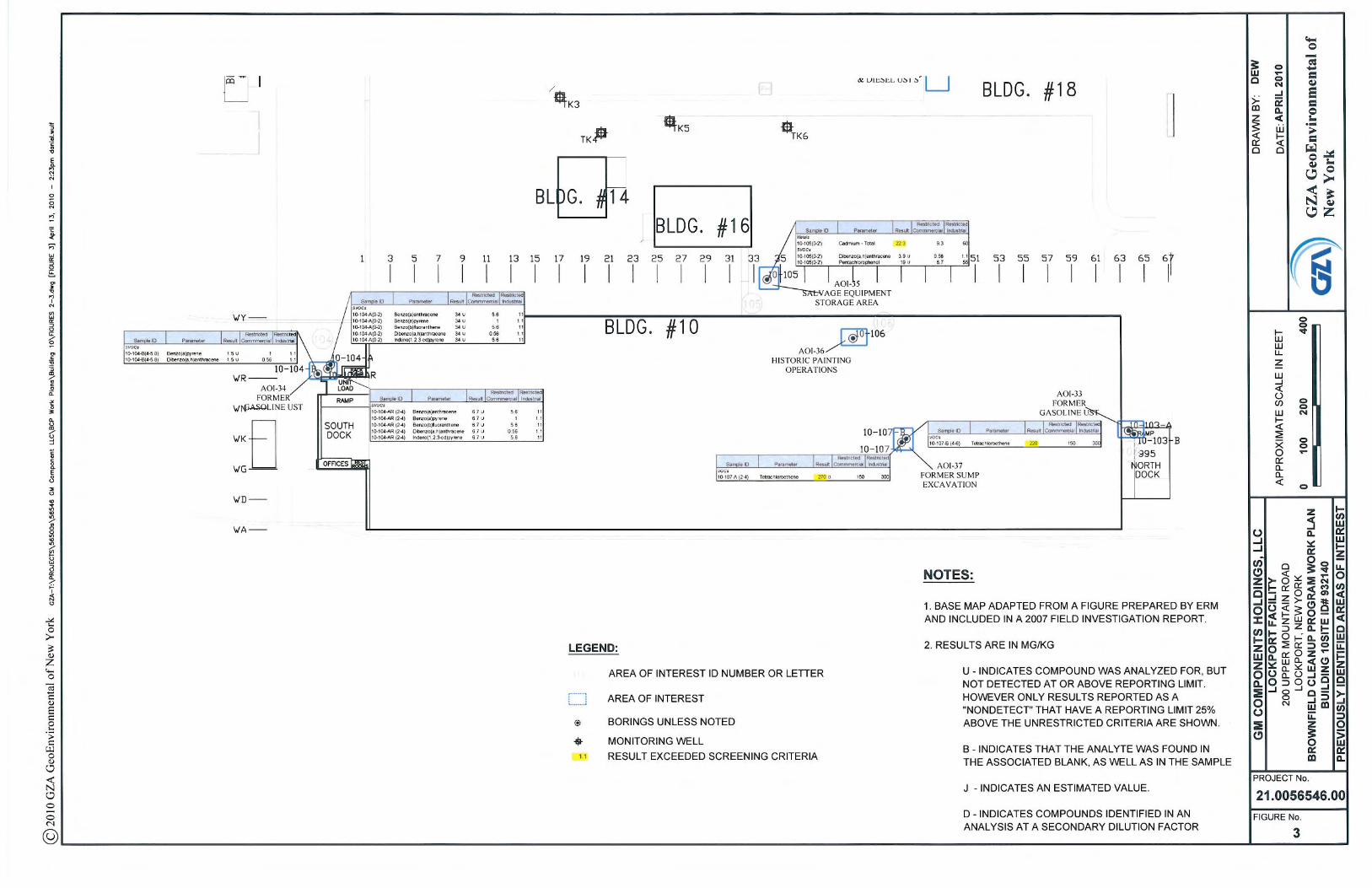
1.3 BACKGROUND GMCH currently owns and operates an automotive component manufacturing facility along Upper Mountain Road in the City and Town of Lockport, New York. The facility was initially developed in 1937 on vacant agricultural land and orchards. The Site was developed as part of an expansion of the manufacturing operations, formerly located in downtown Lockport. Manufacturing operations began at the facility along Upper Mountain Road in 1939. General Motors Corporation owned and operated the facility until it was conveyed to Delphi Automotive Systems, LLC (Delphi) in December 1998. In June 2009, General Motors Corporation filed for Chapter 11 bankruptcy protection and it is now known as Motors Liquidation Company (MLC). A new company was created to purchase certain assets of MLC and the current name of that entity is General Motors LLC (GM). A GM subsidiary, known as GMCH, took title from Delphi of the portion of the facility that includes Building 10 in October 2009. Building 10 was constructed in two sections, the north end in 1960 and the south end in 1969. It was used for warehousing until 1989 when manufacturing equipment installation began in the north end. From 1990 to 2002, the north end of the building was used for manufacturing. In 2007, Building 10 was converted to house new manufacturing operations staffed by non-Delphi personnel in the northern portion with the southern portion continuing to be used by Delphi as a warehouse. In 2006, a voluntary facility-wide investigation of soil and groundwater conditions at the facility was conducted. The first phase of that work was the development of a Current Conditions Summary (CCS) which was completed by Environmental Resource Management (ERM). The CCS work generally followed the requirements for a CCS in the RCRA Corrective Action Program and we believe it was comprehensive, comparable to an initial BCP or State Superfund investigation. After completion of the CCS, a field investigation, also completed by ERM, was initiated to assess soil and groundwater conditions at the 50 areas of interest (AOI), identified by the CCS. A total of 144 soil borings were completed, nine sediment and four surface soil samples were collected. Six monitoring wells were installed, but only five were sampled as one of the wells was dry. Over 400 soil and groundwater samples were collected from the 144 soil borings and analyzed for an extensive list of parameters, which included volatile organic compounds (VOCs), semi-volatile organic compounds (SVOCs), metals and polychlorinated biphenyls (PCBs). The field investigation activities and results were described in the Field Investigation Report (FIR) that was submitted to the NYSDEC Region 9 office in January 2007, followed by the CCS submission in May 2007. Two (2) AOIs, located within the footprint of the Building 10, were investigated as part of the field investigations. AOI-36 was a former painting operation in the western portion of the building and AOI-37 was an area where soil contamination was encountered during construction of a sump in 1999 (see Figure 3). Boring 10-106 was completed in the
3 6/16/2010
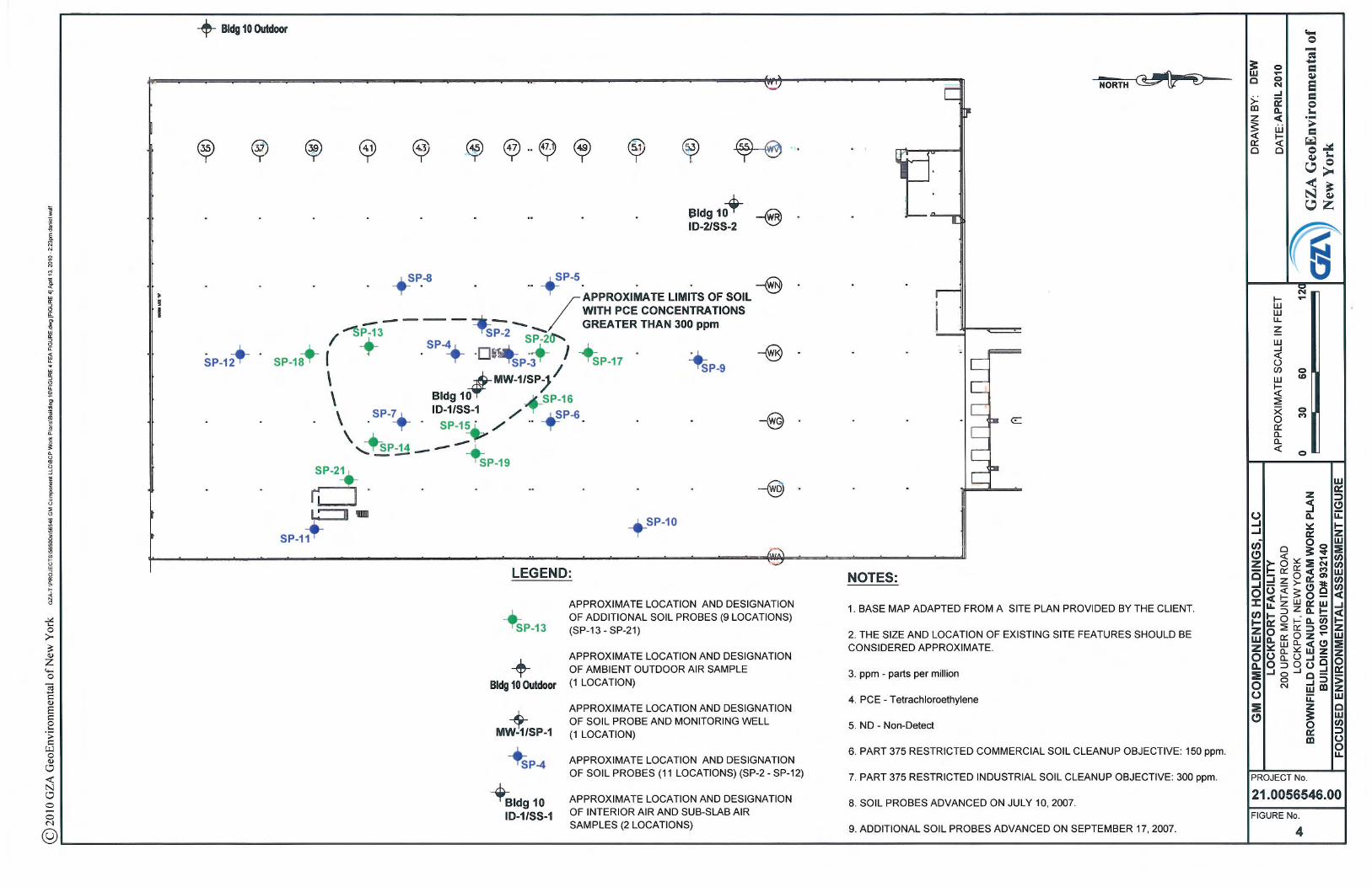
vicinity of AOI-36 and borings 10-107-A and 10-107-B were completed in the vicinity of AOI-37 (see Figure 3). At each AOI, samples were analyzed for VOCs, SVOCs, PCBs, and metals. No detections above NYSDEC Part 375 Commercial Soil Clean-up Objectives (CSCO) were found at AOI 36. At AOI-37, one VOC, tetrachloroethylene (PCE) was detected at a concentration of 270 parts per million (ppm) in one sample, exceeding the CSCO of 150 ppm. Based on the findings described above, a Focused Environmental Assessment1 (FEA) was conducted by GZA. The purpose of the FEA was to determine if the previously identified contamination at AOI-37 required remediation. The FEA was conducted in general accordance with a NYSDEC reviewed work plan in June 2007. The FEA included the completion of 12 soil probes (SP-1 through SP-12), installation of one groundwater monitoring well (Bldg 10 MW-1), and a vapor intrusion (VI) assessment of the northern portion of the building (see Figure 4). The FEA identified elevated concentrations of PCE in the soil samples tested, numerous VOCs were detected above their respective groundwater criteria in the groundwater sample from Bldg 10 MW-1 and a VI concern was identified based on the results of the indoor and sub-slab air samples collected. Additional investigations to further delineate the VOC-impacted soil beneath Building 10 with PCE soil contamination greater than the NYSDEC Part 375 Industrial SCO of 300 ppm were conducted in July 2007. The additional investigations consisted of 9 soil probes (SP-13 through SP-21) and identified an approximate 14,000 square foot area where PCE concentrations were detected at a concentration greater than 300 ppm (see Figure 4). In October 2007, GZA performed a Soil Vapor Extraction (SVE) System Pilot Study to develop the design criteria of the SVE system to be used to treat soil with PCE concentrations greater than 300 ppm. Field activities associated with the pilot study included the installation of two, 4-inch diameter PVC SVE extraction wells, installation of eight vacuum monitoring points via soil probe, mobilization and set up of a mobile extraction system to perform the testing, and two days of pilot testing to collect vacuum and flow rate readings, organic vapor measurements, and analytical air samples. The two pilot test extraction wells were installed within the 14,000 sq ft area. Based on the findings of the additional soil investigation and SVE pilot study, a SVE Pilot Test Summary and SVE System Design Report2 was prepared and submitted to NYSDEC for review. In March 2009, a SVE and sub-slab depressurization system (SSDS) installation was completed and put into operation. The SVE/SSDS Installation Document3 was submitted to NYSDEC for review in July 2009. The SVE System consists of seventeen (17), 4 inch diameter vertical extraction wells installed to depths ranging from 5 to 7 feet below the building slab. The extraction wells were installed on approximate 30 foot centers within the 14,000 sq ft area (see Figure 5). Three trenches were utilized to pipe the 17 extraction
1 “Focused Environmental Assessment, Building 10, Lockport, New York” dated August 27, 2007. GZA File No.: 21.0056340.00 2 “Soil Vapor Extraction (SVE) Pilot Test Summary and SVE System Design Report, Delphi Automotive, Northern Portion of Building 10, Lockport Complex, 200 Upper Mountain Road, Lockport, New York” dated November 2007. GZA File No.: 21.0056364.00 3 “SVE/SSD System Installation Document, Delphi Automotive, Lockport, New York” dated July 2009. GZA File No.: 21.0056445.00
4 6/16/2010
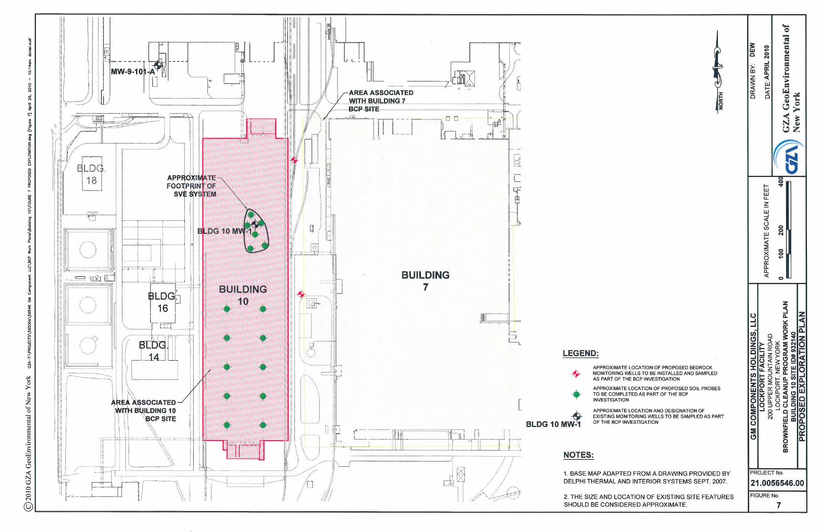
wells to the SVE shed housing the rotary blower. Also within each trench, 2 inch diameter PVC screened piping was installed horizontally within the full length of each of the three trenches (see Figure 5). This piping is also connected to the blower and is acting as a SSDS, extracting potential vapors that may accumulate beneath the concrete slab. 1.4 INVESTIGATION OBJECTIVES The objectives of this RI is to obtain Site specific data on the nature and extent of potential soil and groundwater contamination and the degree to which the potential contamination poses a threat to human health and the environment. On March 18, 2010 GMCH met with NYSDEC to discuss the three BCP sites; NYSDEC acknowledged that VOCs would be the focus of the investigation, with the exception of the soil probes investigation in the southern portion of Building 10 as discussed in Section 2.2.1. Soil samples collected for analysis from the southern portion of the Building 10 will be tested for VOCs, SVOCs, metals and PCBs. Other areas to be investigated will be tested for VOCs only. Proposed soil borings, soil probes and indoor air sample locations, and bedrock monitoring wells related to the Building 10 RI are shown on Figure 7. As there are also RIs occurring related to the Buildings 7 and 8 BCP Sites, the number of explorations associated with Building 10 is limited to Building 10 and the area immediately downgradient (east) between Building 10 and the Building 7 BCP Site (see Figure 7). It should be noted that the RIs for the three BCP Sites at the Lockport facility will be conducted concurrently. Consequently, although the focus of the BCP Agreement for Building 10 is on an evaluation of environmental conditions at the site known as Building 10 (with an approximate acreage of 10.6 acres - see paragraph II of the BCP Agreement), the data generated from the neighboring BCP sites and from other facility-wide investigations that are being conducted (for example, 18 existing monitoring wells will be sampled in 2010 as part of other on-going monitoring and/or investigations (see Figure 6)) will be considered as part of that evaluation. This RI will involve test borings, monitoring well installation, soil probes, and analytical sample collection. The specific objectives of the RI are as follows: • Further assess Site geology; • Further assess hydrogeology; • Evaluate extent of contamination; • Evaluate transport mechanisms; • Assess the potential source(s) of contamination and assess impact to soil and
groundwater; and • Identify potential pathways for human exposure as part of a qualitative risk assessment.
5 6/16/2010
2.0 DESCRIPTION OF FIELD ACTIVITIES The field activities described below are intended to accomplish the objectives of the RI. 2.1 GENERAL FIELD ACTIVITIES General field activities include site meetings, mobilization, implementing the health and safety plan, test borings, sampling and analytical testing, decontamination and handling of investigation wastes, and surveying. Subcontractors will be used for drilling, analytical testing and surveying.
2.1.1 Site Meeting
A Site “kick-off” meeting will be held with GMCH, GZA and the drilling subcontractor(s) prior to initiating field work activities. The purpose of the meeting will be to orient field team members, GMCH staff and subcontractors with the Site, project personnel, Site background, scope of work, potential dangers, health and safety requirements, GMCH site-specific security and safety protocols, emergency contingencies and other field procedures. NYSDEC staff are welcome to attend and will be notified at least seven (7) days in advance of the meeting.
2.1.2 Mobilization
Following approval of the RI Work Plan by NYSDEC, the Underground Facilities Protection Organization (UFPO) will be contacted at 1-800-962-7962 to clear exploration locations. Utility clearance will require three working days by UFPO. Additionally, an Excavation Permit (Environmental Management System Work Instruction 014) will need to be obtained from GMCH Plant Engineering. This will require that exploration locations be approved by GMCH Plant Engineering prior to starting the investigation. GZA and its subcontractors then will mobilize necessary materials and equipment to the Site.
2.1.3 Health and Safety
It is anticipated that the work to be completed at the Site will be done at level D
personal protection. Should health and safety monitoring during field activities indicate a threat to field personnel or warrant an upgrade to level C protection, work will stop, Site conditions will be re-evaluated prior to further investigation activities. See Section 5.0 for additional information on Health and Safety.
2.1.4 Decontamination and Handling of Investigation Derived Waste
Decontamination procedures for the field activities are described in the Equipment Decontamination Field Method Guideline (FMG) included in Appendix A. Personal protective equipment (i.e., latex gloves) and disposable sampling equipment (i.e., polyethylene tubing) will be placed in plastic garbage bags for disposal as a solid waste at the Site.
6 6/16/2010
Excess soil cuttings from test borings and/or soil probes will be drummed and stored on-Site for future disposal. Soil will be characterized for proper disposal at a landfill facility permitted to accept the soil cuttings based on the waste characterization results (i.e., non-hazardous or hazardous). Waste characterization sample analysis will be based on the sampling requirements of the disposal facility selected.
Purge water and well development water will be containerized in 55-gallon drums and stored until analytical results are received. If analytical results are within permissible acceptable limits for discharge to the City of Lockport wastewater treatment facility and authorization is received to do so, drummed water will be discharged to the sanitary sewer. If analytical results do not permit discharge to the sanitary sewer, drummed water will be sampled and characterized for proper disposal. Waste characterization sample analysis will be based on the sampling requirements of the disposal facility selected.
The quantities and volumes of investigation derived waste (IDW) to be generated are unknown and will be managed in accordance with the Waste Characterization Field Method Guide (FMG) in Appendix A.
2.1.5 Survey
Following completion of the RI investigation, a professional land surveying firm
(McIntosh & McIntosh, P.C.) will be subcontracted to locate exploration locations and prepare a Site base map. 2.2 RI FIELD INVESTIGATIONS RI field work will generally be done in compliance with NYSDEC’s Draft DER-10 “Technical Guidance for Site Investigation and Remediation”, dated June 2010. On March 18, 2010 GMCH met with NYSDEC to discuss the three BCP sites. NYSDEC acknowledged that VOCs would be the focus of the investigation, with the exception of the soil probes investigation in the southern portion of Building 10 as discussed in Section 2.2.1. Soil samples collected for analysis from the southern portion of the Building 10 will be tested for VOCs, SVOCs, metals and PCBs. Other areas to be investigated will be tested for VOCs only.
2.2.1 Soil Probes
GZA is proposing to complete six (6) soil probes in the northern portion of the Building 10 and ten (10) soil probes in the southern portion (see Figure 7). The soil probes in the northern portion of Building 10 will be completed in the 14,000 sq ft area of the existing SVE system. The purpose of the six soil probes will be to assess contaminant concentrations in the soil in the northern portion of Building 10, as the SVE system will have been in operation for approximately 18 months at the time of the investigation. After completing the six (6) soil probes, they will be converted to vacuum monitoring points to assess the vacuum distribution of the SVE system in the subsurface. Polyethylene tubing (¼-inch outer diameter) will installed to a depth of approximately 5 feet below ground surface (bgs) within a sand pack. The sand pack will be installed from the bottom of the
7 6/16/2010
soil probe to approximately 2.5 feet below the slab. A bentonite seal will be installed from about 2.5 feet to the bottom of the concrete slab. The vacuum monitoring point will be finished with a flush mounted road box cover. A manometer will be used to measure vacuum readings in the subsurface.
During the March 18, 2010 meeting, NYSDEC requested that GMCH complete
soil probes in the southern portion of the building. The CCS, as previously discussed in Section 1.3, did not identify any AOI in the southern interior portion of Building 10. Therefore, no investigation activities have been performed in the southern interior portion of the building. The proposed soil probes will be completed to provide general coverage of the southern portion of the building. Actual locations will be determined in the field based on rig accessible areas (i.e., GMCH uses the southern portion of Building 10 for storage) and the location of underground utilities. Figure 7 identifies the proposed soil probe locations.
The soil probes will be advanced into overburden soils utilizing direct push
technology via a hydraulic hammer mounted on a truck or track mounted rig equipped with a 2-inch outer diameter by 48-inch long macrocore sampler. Soil probes will be advanced to refusal, which is anticipated to be about 8 feet below the building slab based on previous investigations in the northern portion of the building.
A field engineer/geologist will observe the soil probes and create a field log for each probe. Real time air monitoring will be conducted while soil probes are being completed using an OVM. Soil samples will be collected from the soil probes for classification, laboratory analysis, and screening with the OVM. Soil samples will be collected at two-foot intervals to the bottom of the probes. Samples collected for analytical testing will typically be collected from contaminated soils or material, based on visual, olfactory, field screening and engineering judgment that warrant further analysis. If total organic vapors are not detected above 1 part per million (ppm) during the field screening at a probe location, no soil sample will submitted for laboratory analysis. The soil probe investigation will be completed in accordance with the Drilling Techniques and Soil Boring FMGs included in Appendix A.
2.2.2 Test Boring, Monitoring Well Installation and Sampling
Two (2) permanent monitoring wells will be installed as part of the Building 10 RI.
Figure 7 identifies the proposed monitoring well locations identified. It should be noted that two additional wells are being installed downgradient of Building 10 as part of the Building 7 RI work (see Figure 6). Based on previous work done at the GMCH property in this area, bedrock east of Building 10 is at a depth of approximately 7 to 9 feet below ground surface (bgs). Groundwater at the Site is typically present in the vicinity of the overburden soil and bedrock interface.
Test borings for monitoring well installation will be advanced in the overburden
soils using a track or truck mounted rotary drill rig using 6 ¼ inch inside diameter hollow stem augers (HSA). Overburden soil samples will be obtained by driving a 1 3/8 inch inside diameter by 24 inch long split spoon sampler 24-inches ahead of the lead cutting
8 6/16/2010
shoe of the HAS. The test borings will be completed as outlined in the Soil Boring FMG in Appendix A.
Soil samples collected from the test borings will be classified in the field by visual
examination in accordance with the Soil Classification FMG in Appendix A. Boring logs that identify appropriate stratification lines, blow counts (if applicable), sample identification, sample depth interval and recovery, and date will be generated for each test boring and included as an appendix to the RI report.
The HSAs will be advanced until refusal is encountered. Drilling fluids will not be
used while advancing the HSA in the overburden, so groundwater can be identified, if encountered. Once bedrock is encountered, the upper 2 feet of bedrock will be drilled using a 5 7/8 inch roller bit to set a 4 inch diameter steel casing. The steel casing will be installed, grouted into place and allowed to set up for at least 12 hours before drilling activities continue at the respective location. Once the grout around the casing has set up, a 3 7/8 inch diameter rock core barrel will be used to complete the boring to the designated depth, assumed to be approximately 15 feet bgs.
The rock core samples will be logged including run number, sample interval, length of sample recovered, rock quality designation (RQD), depth where drill water was lost, and a description of the rock mass and individual discontinuities (bedding planes, joints, voids, etc.). This information will be included on the boring logs. Rock core samples will be placed in wooden core boxes, photographed and labeled with the project name and number, boring number, run number, depth interval of the run and date. The rock core boxes shall be stored by GMCH for 1 year. The bedrock coring will be completed as outlined in the Bedrock Coring and Rock Classification FMGs in Appendix A.
After the designated depth has been reached, the completed test boring will be converted to a groundwater monitoring well. The well will be constructed of 2-inch inner diameter flush coupled PVC riser and screen. The screen will consist of an approximate 5 to 7-foot long section of machine slotted PVC. A sand filter will be placed in the boring around the annulus space of the well screen such that the sand extends a minimum of 1-foot above the top of the screen. An approximate 3-foot thick layer of bentonite will be placed above the sand filter to provide a seal from the overburden conditions above the screen. A mixture of cement/bentonite grout will extend from the bentonite seal to approximately 1-feet bgs. The monitoring well will be completed by placing a flush mounted road box over the riser. Concrete will be placed in the boring around the protective casing and sloped away from the casing. The monitoring wells will be installed as outlined in the Well Construction Materials and Deep Bedrock Wells FMG in Appendix A.
The soil spoils generated from the test boring will be placed in 55-gallon drums for
disposal by GMCH. The drums will be labeled with date and location and staged in a secure area at the Site approved by GMCH. GZA assumes the soil spoils generated from the test borings will not be contaminated. Procedures discussed in Section 2.1.4 will be utilized to determine the handling of the soil spoils.
9 6/16/2010
The test borings will be observed by a field engineer/geologist and a field log for each boring/monitoring well will be created. Real time air monitoring will be conducted while test borings are being completed using an OVM. Soil samples will be collected at two-foot intervals to the bottom of the boring for classification, laboratory analysis and screening with the OVM. Soil samples collected for analytical testing will typically be collected from contaminated soils or material, based on visual, olfactory, field screening (OVM) and engineering judgment that warrant further assessment. One soil sample will be collected for analytical testing from each test boring. The soil sampling will be conducted utilizing the Soil Sampling FMG in Appendix A.
The monitoring wells will be developed to remove the fines and develop the sand filter pack utilizing the Well Development FMG in Appendix A. Hydraulic conductivity testing will be performed to assess whether the monitoring well is functioning and provide hydrologic information in accordance with the In Situ Hydraulic Conductivity (Slug Test) Procedure FMG in Appendix A. Water level measurements will be collected to interpret groundwater flow direction as outline in the Water Level Measurements FMG in Appendix A.
Groundwater samples will be collected from the two newly installed monitoring
wells and two existing wells (Bldg 10 MW-1, located inside Building 10 and MW-9-101-A, located just south of Building 9, see Figure 6). Groundwater sampling will be conducted utilizing low-flow sampling techniques as outlined in the Groundwater Sampling FMG in Appendix A. A water quality meter, disposable polyethylene tubing and a variable speed peristaltic pump will be utilized during the monitoring and sampling.
Water generated during development and purging prior to sampling will be
containerized until the analytical results of the groundwater samples are received. IDW will be managed as described in Section 2.1.4.
2.2.3 Indoor Air Sampling Two (2) indoor air samples will be collected as part of the Building 10 RI. Figure 7
identifies the proposed indoor air sampling locations. The samples will be collected using dedicated, laboratory-supplied flow regulators and sample canisters over an 8-hour period. The indoor air sampling locations will be similar to the two sample location utilized as part of the Building FEA discussed in Section 1.3. The indoor samples will be compared to the indoor air data previously collected and the New York State Department of Health Indoor Air criteria to determine the effectiveness of the SVE/SSD System currently operating in the northern portion of Building 10. In addition to the indoor air samples, one (1) exterior outdoor air sample will be collected concurrently with the indoor air samples to assess the potential impact of outdoor on the indoor air sampling results.
2.2.4 Fish and Wildlife Resources Impact Analysis
A fish and wildlife impact analysis that characterizes resources used to identify potential or actual impacts will be performed for the Site (Part 1 assessment – see NYSDEC Draft DER-10). If no fish or wildlife resources or ecological exposure pathways
10 6/16/2010
are identified, then this component of the work will be considered complete. If there is a potential for fish and wildlife impacts, then a plan will be developed to implement a preliminary ecological impact assessment (Part 2). 2.3 ENVIRONMENTAL ANALYTICAL TESTING PROGRAM The environmental testing program is summarized in Table 1. The location for sample collection will be determined based upon the results of the field screening and engineering judgment. The samples collected as part of this RI will be subject to analytical testing methodologies that follow NYSDEC Analytical Service Protocol (ASP) Category B deliverables and data validation. Further information regarding sampling and testing methodologies can be found in the QAPP (see Section 4.0). Samples submitted for analytical testing will be given a unique sample designation. The sample designation will be done in accordance with the Sample Handling and Shipping FMG included in Appendix A. 2.4 SURVEY The survey will be done after completion of the fieldwork to locate soil probes and monitoring wells. This will allow measurement of the actual exploration locations and elevations. A licensed land surveyor will be subcontracted to do the survey. Vertical measurements will include a ground surface elevation, plus top of casing and top of riser for monitoring wells. The top of riser will serve as the water level monitoring point. Vertical measurements will be made relative to the National Geodetic Vertical Datum (NGVD). Monitoring point measurements and top of protective casing measurements will be accurate to within 0.01 foot. Horizontal measurements and ground surface elevations will be accurate to within 0.1 foot. The base map for the Site will include pertinent Site features and the investigation exploration locations.
3.0 ADDITIONAL FIELD EXPLORATIONS If determined to be necessary, contingent field explorations for the RI may be conducted. This work may consist of additional soil probes and monitoring well installations for supplemental soil and groundwater data to complement or fill in data gaps from the initial RI, if deemed necessary. If needed, a scope of work will be developed for review by NYSDEC prior to initialing additional investigation activities. The work activities will be completed according to the procedures described in this RIWP and any subsequently approved modifications.
11 6/16/2010
4.0 QUALITY ASSURANCE/QUALITY CONTROL
The Quality Assurance and Quality Control (QA/QC) for the Building 10 RI are discussed in the “GM Components Holdings, LLC, Brownfield Cleanup Program, Quality Assurance and Quality Control Plan, Building 7 (Site ID #C932138), Building 8 (Site ID #932139) and Building 10 (Site ID #C932140), Lockport Facility, 200 Upper Mountain Road, Lockport, New York” dated June 2010. The QA/QC Plan presents the objectives and specific QA/QC procedures associated with the RI activities planned for Building 10. Protocols for sample collection, sample handling and storage, Chain of Custody procedures, and laboratory and field analyses are described or specifically referenced to related investigation documents.
5.0 HEALTH AND SAFETY PROTOCOLS
The health and safety protocols for the Building 10 RI are discussed in the “Site Health and Safety Plan, GM Components Holdings, LLC, Brownfield Cleanup Program, Building 7 (Site ID #C932138), Building 8 (Site ID #932139) and Building 10 (Site ID #C932140), Lockport Facility, 200 Upper Mountain Road, Lockport, New York” dated April 20, 2010. The Health and Safety Plan presents specific health and safety protocols associated with the RI activities planned for Building 10.
6.0 SCHEDULE
The following schedule is associated with the Building 10 field activities and RI report preparation. Submit Building 10 RI Work Plans: June 18, 2010 Perform Building 10 RI: July through August 2010 (Timing depends on coordinating subsurface investigations with manufacturing activities) Submittal of RI Report: February 2011 Submittal of Alternative Analysis Report: June 2011
12 6/16/2010
7.0 CITIZEN PARTICIPATION
The Citizen Participation (CP) proponents for the Building 10 RI are discussed in the “Brownfield Cleanup Program, Citizen Participation Plans, GM Components Holdings, LLC, Building 7 Site ID #C932138, Building 8 Site ID #932139 and Building 10 Site ID #C932140, 200 Upper Mountain Road, City of Lockport, New York” dated June 2010. The CP Plan outlines how members of the affected and interested public are provided with information about how NYSDEC will inform and involve them during the investigation and remediation of the Site. Information such as project contacts, document repositories, site contact lists and CP activities are provided in the CP Plan.
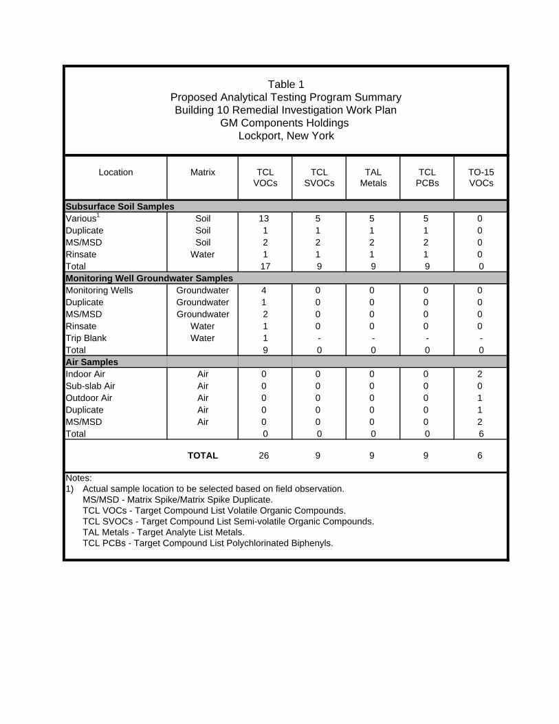
Table 1Proposed Analytical Testing Program SummaryBuilding 10 Remedial Investigation Work Plan
GM Components Holdings Lockport, New York
Location Matrix TCL TCL TAL TCL TO-15VOCs SVOCs Metals PCBs VOCs
Subsurface Soil SamplesVarious1 Soil 13 5 5 5 0Duplicate Soil 1 1 1 1 0MS/MSD Soil 2 2 2 2 0Rinsate Water 1 1 1 1 0Total 17 9 9 9 0Monitoring Well Groundwater SamplesMonitoring Wells Groundwater 4 0 0 0 0Duplicate Groundwater 1 0 0 0 0MS/MSD Groundwater 2 0 0 0 0Rinsate Water 1 0 0 0 0Trip Blank Water 1 - - - -Total 9 0 0 0 0Air SamplesIndoor Air Air 0 0 0 0 2Sub-slab Air Air 0 0 0 0 0Outdoor Air Air 0 0 0 0 1Duplicate Air 0 0 0 0 1MS/MSD Air 0 0 0 0 2Total 0 0 0 0 6
TOTAL 26 9 9 9 6
Notes:1) Actual sample location to be selected based on field observation.
MS/MSD - Matrix Spike/Matrix Spike Duplicate.TCL VOCs - Target Compound List Volatile Organic Compounds.TCL SVOCs - Target Compound List Semi-volatile Organic Compounds.TAL Metals - Target Analyte List Metals.TCL PCBs - Target Compound List Polychlorinated Biphenyls.