gmpls overview - snummlab.snu.ac.kr/links/hsn/workshop/hsn2002/documents/ix_1.pdfmultimedia...
TRANSCRIPT

Multimedia Networking Lab 2
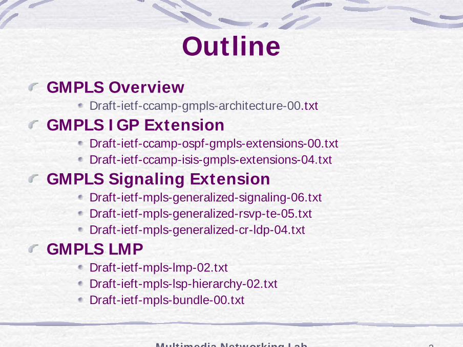
OutlineGMPLS Overview
Draft-ietf-ccamp-gmpls-architecture-00.txt
GMPLS IGP ExtensionDraft-ietf-ccamp-ospf-gmpls-extensions-00.txtDraft-ietf-ccamp-isis-gmpls-extensions-04.txt
GMPLS Signaling ExtensionDraft-ietf-mpls-generalized-signaling-06.txtDraft-ietf-mpls-generalized-rsvp-te-05.txtDraft-ietf-mpls-generalized-cr-ldp-04.txt
GMPLS LMPDraft-ietf-mpls-lmp-02.txtDraft-ieft-mpls-lsp-hierarchy-02.txtDraft-ietf-mpls-bundle-00.txt
Multimedia Networking Lab 3
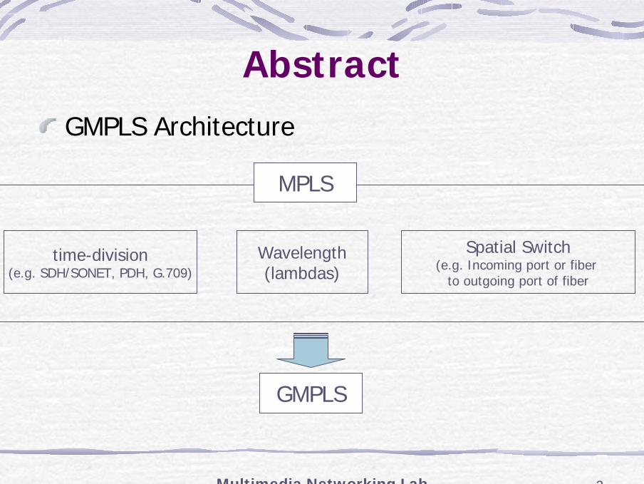
AbstractGMPLS Architecture
time-division(e.g. SDH/SONET, PDH, G.709)
Wavelength(lambdas)
Spatial Switch(e.g. Incoming port or fiber
to outgoing port of fiber
MPLS
GMPLS
Multimedia Networking Lab 4
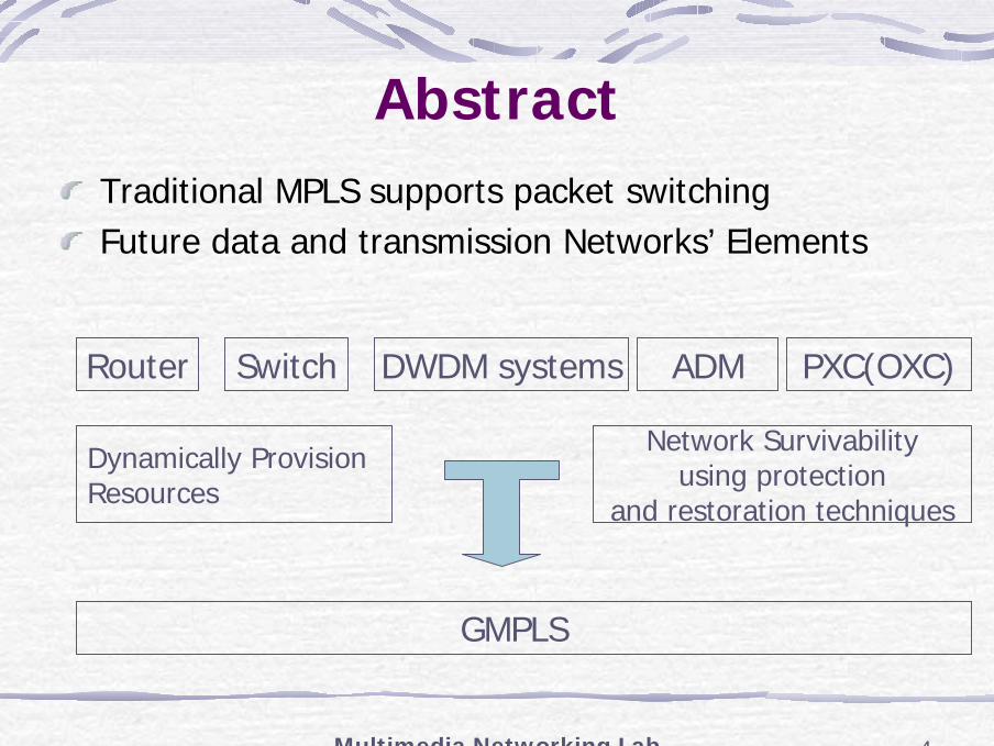
AbstractTraditional MPLS supports packet switchingFuture data and transmission Networks’ Elements
Router Switch DWDM systems ADM PXC(OXC)
GMPLS
Dynamically Provision Resources
Network Survivabilityusing protection
and restoration techniques
Multimedia Networking Lab 5
GMPLS GoalsA single network-wide control plane to
Distribute optical transport network topology stateSet up optical channel trails
Support traffic engineering functions and enable protection and restoration capabilitiesSimplify the integration of optical switches, optical transport, and label switching routersEnhances service provider revenues
New services creation, Faster provisioning, Operational efficiency
Multimedia Networking Lab 6
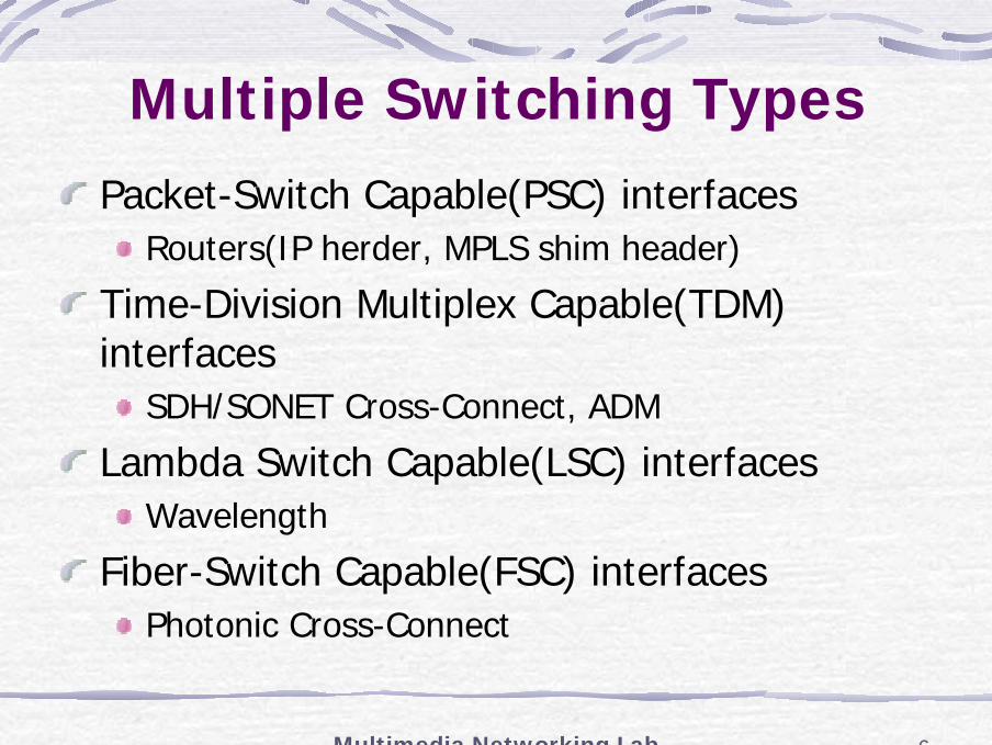
Multiple Switching TypesPacket-Switch Capable(PSC) interfaces
Routers(IP herder, MPLS shim header)
Time-Division Multiplex Capable(TDM) interfaces
SDH/SONET Cross-Connect, ADM
Lambda Switch Capable(LSC) interfacesWavelength
Fiber-Switch Capable(FSC) interfacesPhotonic Cross-Connect
Multimedia Networking Lab 7
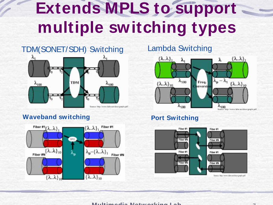
Extends MPLS to support multiple switching types
Lambda Switching
Waveband switching Port Switching
TDM(SONET/SDH) Switching
Multimedia Networking Lab 8
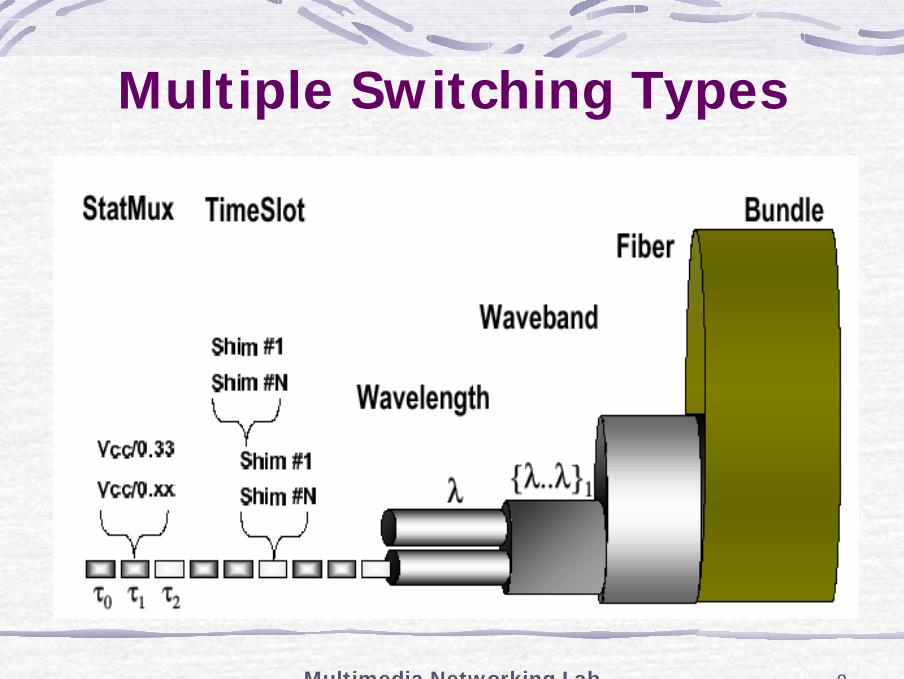
Multiple Switching Types
Multimedia Networking Lab 9
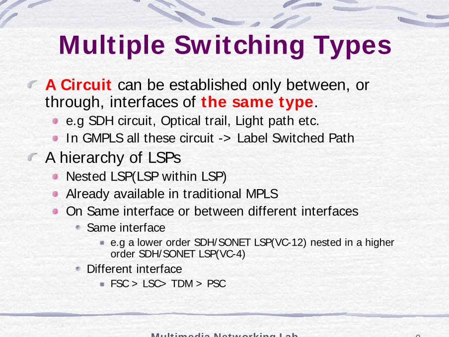
Multiple Switching TypesA Circuit can be established only between, or through, interfaces of the same type.
e.g SDH circuit, Optical trail, Light path etc.In GMPLS all these circuit -> Label Switched Path
A hierarchy of LSPsNested LSP(LSP within LSP)Already available in traditional MPLSOn Same interface or between different interfaces
Same interfacee.g a lower order SDH/SONET LSP(VC-12) nested in a higher order SDH/SONET LSP(VC-4)
Different interfaceFSC > LSC> TDM > PSC
Multimedia Networking Lab 10
Extension of MPLS Control PlaneGMPLS
Extend control planes to support of the four classes of interfaces
GMPLS Building BlockThe Main Building Blocks
To build a consistent control plane for multiple switching layers.Different models can be applied : e.g.overlay, peer, augmented/integrated, A number of combinations are possible.
Multimedia Networking Lab 11
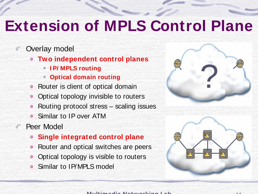
Extension of MPLS Control PlaneOverlay model
Two independent control planesIP/MPLS routingOptical domain routing
Router is client of optical domainOptical topology invisible to routersRouting protocol stress – scaling issuesSimilar to IP over ATM
Peer ModelSingle integrated control planeRouter and optical switches are peersOptical topology is visible to routersSimilar to IP/MPLS model
?
Multimedia Networking Lab 12
Extension of MPLS Control PlaneGMPLS can be summarized as follows
The Concepts of Generalized InterfaceA new Link Management Protocol(LMP)
To address issues related to link management in optical networks using photonic switches
Traffic Engineering EnhancementsEnhancements to OSPF/IS-IS
To advertise availability of optical resources in the networks(e.q. Generalized representation of various link types, bandwidth on wavelengths, link protection type, fiber identifiers)
Enhancements to RSVP-TE/CR-LDPTo allow a LSP to be explicitly specified across the optical core.
Scalability enhancementssuch as hierarchical LSP formation, Link Bundling
Multimedia Networking Lab 13
Key Difference(1)
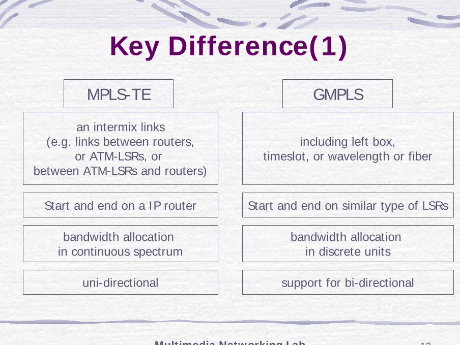
MPLS-TE GMPLS
an intermix links(e.g. links between routers,
or ATM-LSRs, or between ATM-LSRs and routers)
including left box,timeslot, or wavelength or fiber
Start and end on a IP router Start and end on similar type of LSRs
bandwidth allocation in continuous spectrum
bandwidth allocation in discrete units
uni-directional support for bi-directional
Multimedia Networking Lab 14
Key Difference(2)GMPLS
Expected to have(much) fewer labels on non-PSC links than on PSC linksForwarding Adjacency(FA) mechanism
to improve bandwidth utilizationto aggregate forwarding stateallowing the number of required labels to be reduced
Allowing for a label to be suggested by an upstream node
to reduce setup latencyGMPLS with RSVP-TE supports an RSVP specific mechanism for rapid failure notification
Multimedia Networking Lab 15
Key Difference(3)An ingress or other upstream node may restrict the labels(Label Set) that may be used by an LSP along either a single hop or along the whole LSP pathConstraining Label Choice
Some switches cannot modify labels (lambdas)May want to restrict available resourcesAdvertise available lambdas using ‘Label Set’Label set is allowed to have just one member
Multimedia Networking Lab 16
GMPLS Scalability EnhancementGMPLS
The overall number of links in optical/TDM can be several orders of magnitude larger than that of an MPLS network -> Link BundlingIdentifying which port on a network element is connected to which port on a neighboring network element is also a major management burden and highly error-prone -> LMPFast fault detection and isolation, and fast failover to an alternate channel are needed -> LMPThe user data carried in the optical domain is transparently switched to increase the efficiency of the network -> LMP
Multimedia Networking Lab 17
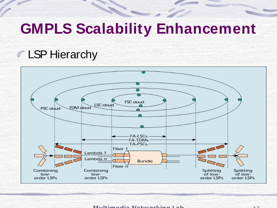
GMPLS Scalability Enhancement
LSP Hierarchy
Multimedia Networking Lab 18
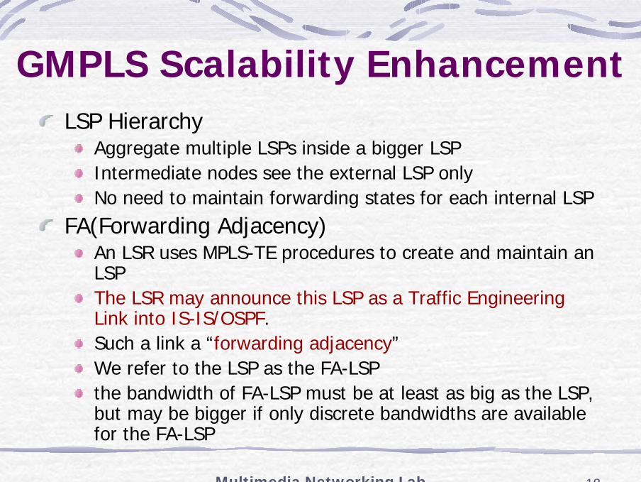
GMPLS Scalability EnhancementLSP Hierarchy
Aggregate multiple LSPs inside a bigger LSPIntermediate nodes see the external LSP onlyNo need to maintain forwarding states for each internal LSP
FA(Forwarding Adjacency)An LSR uses MPLS-TE procedures to create and maintain an LSPThe LSR may announce this LSP as a Traffic Engineering Link into IS-IS/OSPF.Such a link a “forwarding adjacency”We refer to the LSP as the FA-LSPthe bandwidth of FA-LSP must be at least as big as the LSP, but may be bigger if only discrete bandwidths are available for the FA-LSP
Multimedia Networking Lab 19
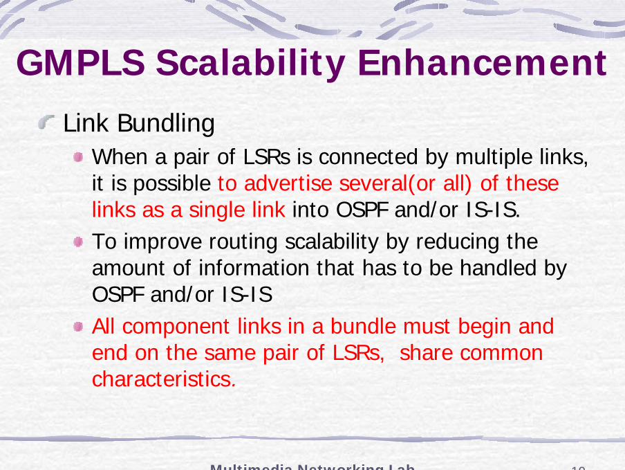
GMPLS Scalability EnhancementLink Bundling
When a pair of LSRs is connected by multiple links, it is possible to advertise several(or all) of these links as a single link into OSPF and/or IS-IS.To improve routing scalability by reducing the amount of information that has to be handled by OSPF and/or IS-ISAll component links in a bundle must begin and end on the same pair of LSRs, share common characteristics.
Multimedia Networking Lab 20
GMPLS Routing & Addressing model(1)
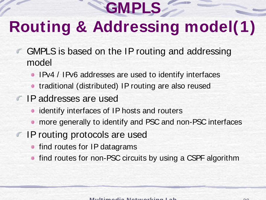
GMPLS is based on the IP routing and addressing model
IPv4 / IPv6 addresses are used to identify interfacestraditional (distributed) IP routing are also reused
IP addresses are used identify interfaces of IP hosts and routersmore generally to identify and PSC and non-PSC interfaces
IP routing protocols are usedfind routes for IP datagramsfind routes for non-PSC circuits by using a CSPF algorithm
Multimedia Networking Lab 21
GMPLS Routing & Addressing model(2)
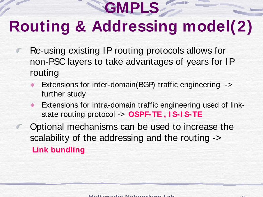
Re-using existing IP routing protocols allows for non-PSC layers to take advantages of years for IP routing
Extensions for inter-domain(BGP) traffic engineering -> further studyExtensions for intra-domain traffic engineering used of link-state routing protocol -> OSPFOSPF--TE , ISTE , IS--ISIS--TETE
Optional mechanisms can be used to increase the scalability of the addressing and the routing ->Link bundling Link bundling
Multimedia Networking Lab 22
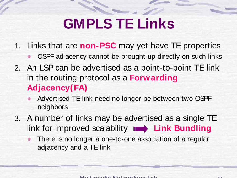
GMPLS TE Links1. Links that are non-PSC may yet have TE properties
OSPF adjacency cannot be brought up directly on such links
2. An LSP can be advertised as a point-to-point TE link in the routing protocol as a Forwarding Adjacency(FA)
Advertised TE link need no longer be between two OSPF neighbors
3. A number of links may be advertised as a single TE link for improved scalability Link Bundling
There is no longer a one-to-one association of a regular adjacency and a TE link

Multimedia Networking Lab 23
RSVP-TE / CR-LDP Extensions
PATH / REQUEST MessageGeneralized Label Request, Explicit RouteUpstream Label, Label Set, Suggested Label
RESV / MAPPING MessageGeneralized Label
SONET/SDHADM
SONET/SDHADM
RESV/MAPPINGRESV/MAPPING
PATH/REQUESTPATH/REQUEST
Multimedia Networking Lab 24
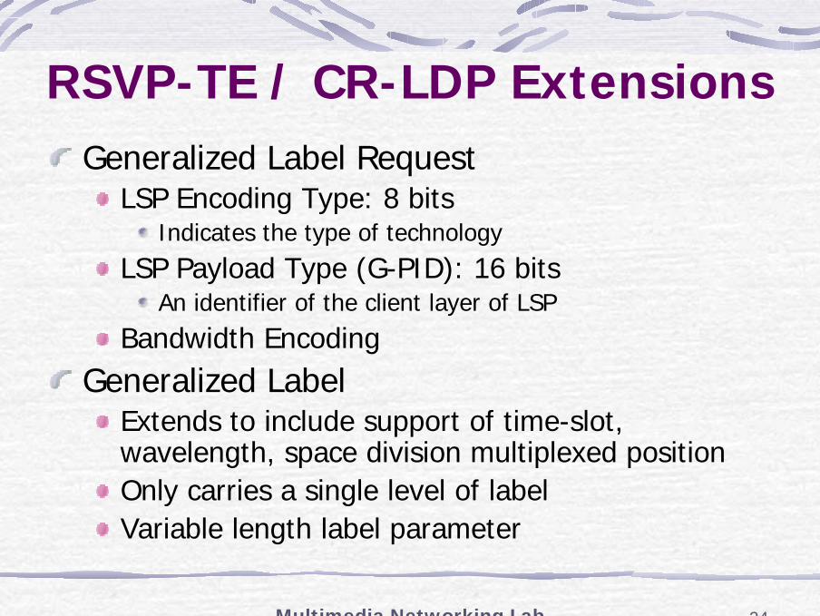
RSVP-TE / CR-LDP ExtensionsGeneralized Label Request
LSP Encoding Type: 8 bitsIndicates the type of technology
LSP Payload Type (G-PID): 16 bitsAn identifier of the client layer of LSP
Bandwidth EncodingGeneralized Label
Extends to include support of time-slot, wavelength, space division multiplexed positionOnly carries a single level of labelVariable length label parameter
Multimedia Networking Lab 25
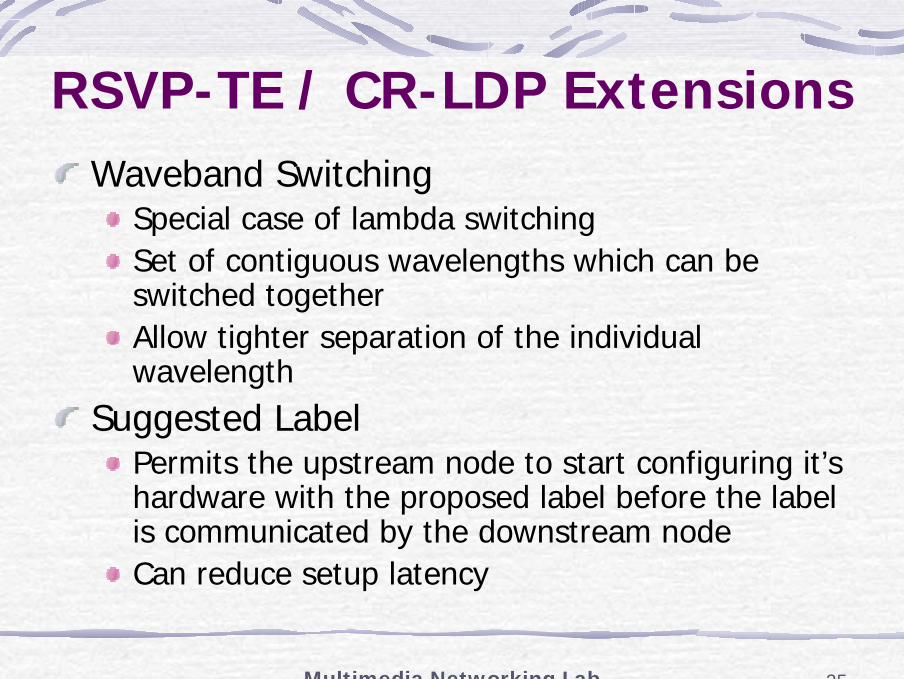
RSVP-TE / CR-LDP ExtensionsWaveband Switching
Special case of lambda switchingSet of contiguous wavelengths which can be switched togetherAllow tighter separation of the individual wavelength
Suggested LabelPermits the upstream node to start configuring it’s hardware with the proposed label before the label is communicated by the downstream nodeCan reduce setup latency
Multimedia Networking Lab 26
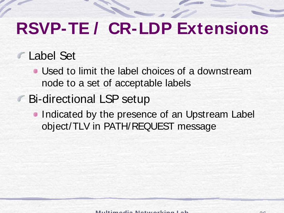
RSVP-TE / CR-LDP ExtensionsLabel Set
Used to limit the label choices of a downstream node to a set of acceptable labels
Bi-directional LSP setupIndicated by the presence of an Upstream Label object/TLV in PATH/REQUEST message
Multimedia Networking Lab 27
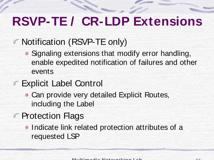
RSVP-TE / CR-LDP ExtensionsNotification (RSVP-TE only)
Signaling extensions that modify error handling, enable expedited notification of failures and other events
Explicit Label ControlCan provide very detailed Explicit Routes, including the Label
Protection FlagsIndicate link related protection attributes of a requested LSP
Multimedia Networking Lab 28
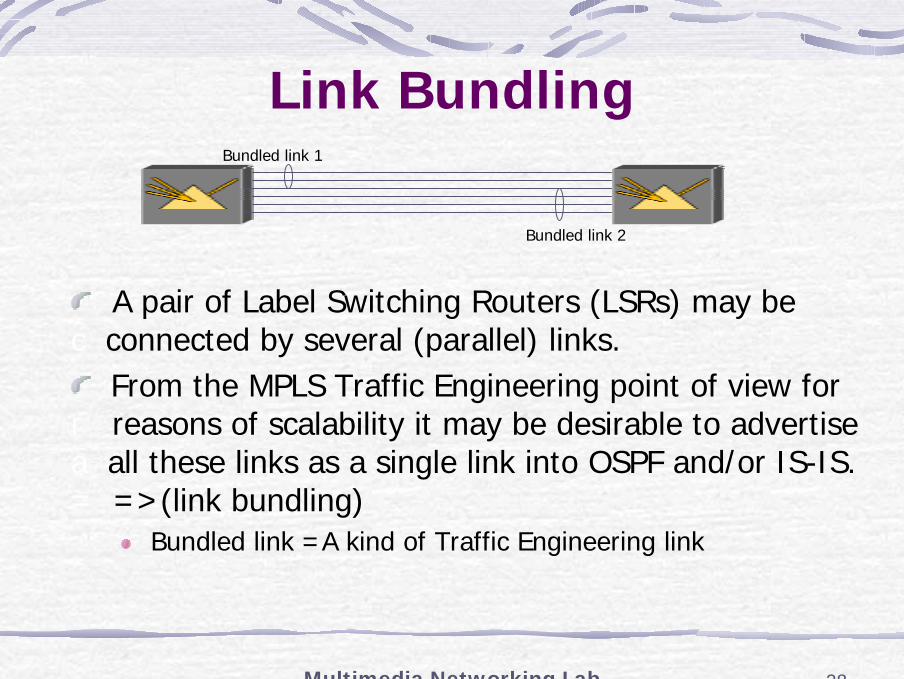
Link BundlingBundled link 1
Bundled link 2
A pair of Label Switching Routers (LSRs) may be c connected by several (parallel) links.
From the MPLS Traffic Engineering point of view for r reasons of scalability it may be desirable to advertise a all these links as a single link into OSPF and/or IS-IS. = =>(link bundling)
Bundled link =A kind of Traffic Engineering link
Multimedia Networking Lab 29
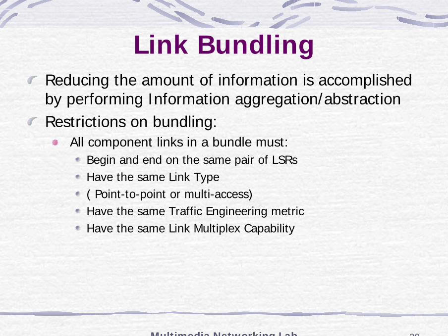
Link BundlingReducing the amount of information is accomplished by performing Information aggregation/abstraction Restrictions on bundling:
All component links in a bundle must:Begin and end on the same pair of LSRsHave the same Link Type( Point-to-point or multi-access)Have the same Traffic Engineering metricHave the same Link Multiplex Capability
Multimedia Networking Lab 30
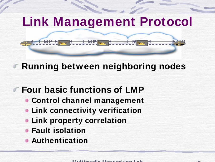
Link Management Protocol
Running between neighboring nodes
Four basic functions of LMPControl channel managementLink connectivity verificationLink property correlationFault isolationAuthentication
LMP LMP LMP LMP
Multimedia Networking Lab 31
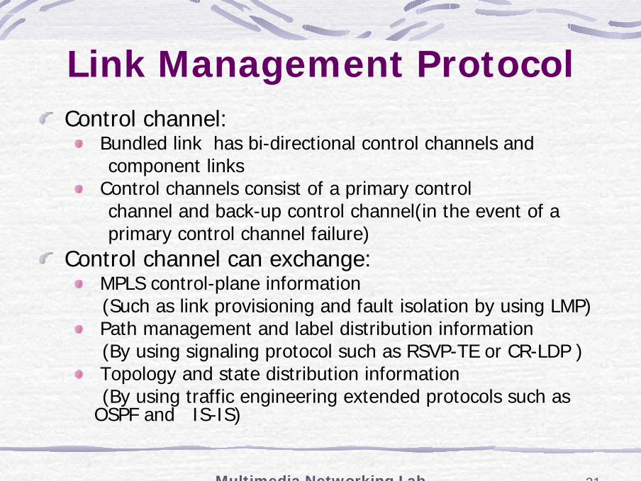
Link Management ProtocolControl channel:
Bundled link has bi-directional control channels andcomponent links
Control channels consist of a primary controlchannel and back-up control channel(in the event of aprimary control channel failure)
Control channel can exchange:MPLS control-plane information(Such as link provisioning and fault isolation by using LMP)Path management and label distribution information(By using signaling protocol such as RSVP-TE or CR-LDP )Topology and state distribution information (By using traffic engineering extended protocols such as
OSPF and IS-IS)
Multimedia Networking Lab 32
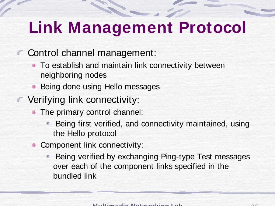
Link Management ProtocolControl channel management:
To establish and maintain link connectivity between neighboring nodes Being done using Hello messages
Verifying link connectivity:The primary control channel:
Being first verified, and connectivity maintained, using the Hello protocol
Component link connectivity:Being verified by exchanging Ping-type Test messages over each of the component links specified in the bundled link
Multimedia Networking Lab 33
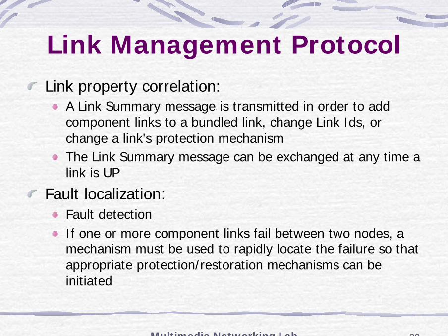
Link Management ProtocolLink property correlation:
A Link Summary message is transmitted in order to add component links to a bundled link, change Link Ids, or change a link's protection mechanism The Link Summary message can be exchanged at any time a link is UP
Fault localization:Fault detectionIf one or more component links fail between two nodes, a mechanism must be used to rapidly locate the failure so that appropriate protection/restoration mechanisms can be initiated