gmr 18/24 gmr 18 hd/24 hd - fondriest environmental, inc.€¦ · garmin radome installation...
TRANSCRIPT
GMR 18/24
radome
installation instructions
GMR 18 HD/24 HD
© 2007-2008 Garmin Ltd. or its subsidiariesGarmin International, Inc. 1200 East 151st Street, Olathe, Kansas 66062, USA Tel. (913) 397.8200 or (800) 800.1020 Fax (913) 397.8282
Garmin (Europe) Ltd. Liberty House Hounsdown Business Park, Southampton, Hampshire, SO40 9RB UK Tel. +44 (0) 870.8501241 (outside the UK) 0808 2380000 (within the UK) Fax +44 (0) 870.8501251
Garmin Corporation No. 68, Jangshu 2nd Road, Shijr, Taipei County, Taiwan Tel. 886/2.2642.9199 Fax 886/2.2642.9099
All rights reserved. Except as expressly provided herein, no part of this manual may be reproduced, copied, transmitted, disseminated, downloaded or stored in any storage medium, for any purpose without the express prior written consent of Garmin. Garmin hereby grants permission to download a single copy of this manual onto a hard drive or other electronic storage medium to be viewed and to print one copy of this manual or of any revision hereto, provided that such electronic or printed copy of this manual must contain the complete text of this copyright notice and provided further that any unauthorized commercial distribution of this manual or any revision hereto is strictly prohibited.Information in this document is subject to change without notice. Garmin reserves the right to change or improve its products and to make changes in the content without obligation to notify any person or organization of such changes or improvements. Visit the Garmin Web site (www.garmin.com) for current updates and supplemental information concerning the use and operation of this and other Garmin products.Raymarine® is a registered trademark of Raymarine Ltd. Garmin® is a trademark of Garmin Ltd. or its subsidiaries, registered in the USA and other countries. This trademark may not be used without the express permission of Garmin.
February 2008 Part Number 190-00831-02 Rev. C Printed in Taiwan

Garmin Radome Installation Instructions �
IntroductIonThank you for choosing a Garmin radome. This radome utilizes the performance of Garmin radar and provides overlay and color information when combined with a Garmin marine network chartplotter.
Product RegistrationHelp us better support you by completing our online registration today! Connect to our Web site at http://my.garmin.com. Keep the original sales receipt, or a photocopy, in a safe place.
Contact GarminContact Garmin if you have any questions while using your Garmin radome. In the USA contact Garmin Product Support by phone: (913) 397-8200 or (800) 800-1020 or go to www.garmin.com/support/.
In Europe, contact Garmin (Europe) Ltd. at +44 (0) 870.8501241 (outside the UK) or 0808 2380000 (within the UK).
Note: The Garmin radome has no user-serviceable parts. If you encounter a problem with your unit, please take it to an authorized Garmin NMEA dealer or contact Garmin Product Support for repairs.
Packing ListBefore installing and getting started with your unit, check that your package includes the following items. If any parts are missing, please contact your Garmin dealer immediately.Standard Package:
GMR 18/24 radome or GMR 18 HD/24 HD radomePower cableMarine network cableField install RJ-45 network cable connectorMounting kit hardwareMounting templateGrommet for marine cable
•••••••
� Garmin Radome Installation Instructions
InstallatIon
Radome InstallationThe following section covers the installation and setup of the Garmin radome. The Garmin radome only operates with Garmin chartplotters through a Garmin marine network. See your Garmin dealer or the Garmin Web site for more details.
To complete the installation, you need the appropriate fasteners, tools, and mounts. These items should be available at most marine dealers. Always wear safety goggles, ear protection, and a dust mask when drilling, cutting, or sanding. When drilling or cutting, always check first to see what is on the other side of the surface. If you experience difficulty with the installation, contact Garmin Product Support or seek the assistance of a professional installer.
Installation GuidelinesTo maximize the performance of the radar, observe the following installation guidelines:
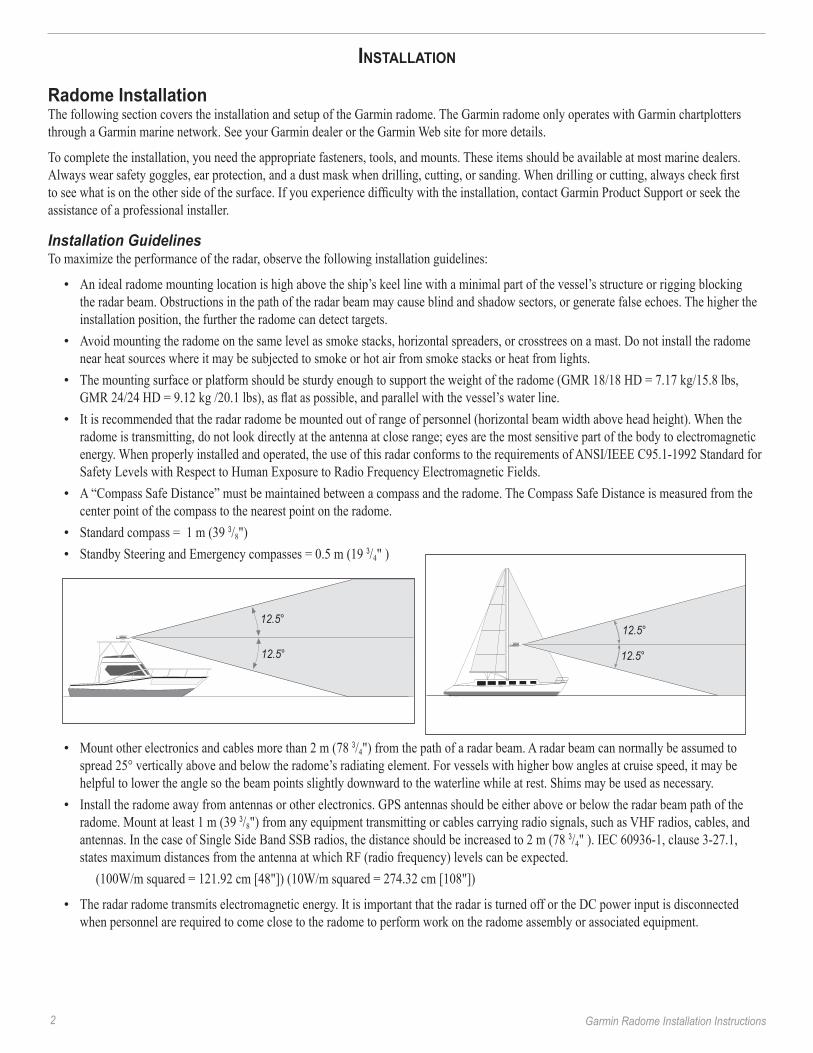
An ideal radome mounting location is high above the ship’s keel line with a minimal part of the vessel’s structure or rigging blocking the radar beam. Obstructions in the path of the radar beam may cause blind and shadow sectors, or generate false echoes. The higher the installation position, the further the radome can detect targets. Avoid mounting the radome on the same level as smoke stacks, horizontal spreaders, or crosstrees on a mast. Do not install the radome near heat sources where it may be subjected to smoke or hot air from smoke stacks or heat from lights.The mounting surface or platform should be sturdy enough to support the weight of the radome (GMR 18/18 HD = 7.17 kg/15.8 lbs, GMR 24/24 HD = 9.12 kg /20.1 lbs), as flat as possible, and parallel with the vessel’s water line. It is recommended that the radar radome be mounted out of range of personnel (horizontal beam width above head height). When the radome is transmitting, do not look directly at the antenna at close range; eyes are the most sensitive part of the body to electromagnetic energy. When properly installed and operated, the use of this radar conforms to the requirements of ANSI/IEEE C95.1-1992 Standard for Safety Levels with Respect to Human Exposure to Radio Frequency Electromagnetic Fields.A “Compass Safe Distance” must be maintained between a compass and the radome. The Compass Safe Distance is measured from the center point of the compass to the nearest point on the radome.Standard compass = 1 m (39 3/8") Standby Steering and Emergency compasses = 0.5 m (19 3/4" )
Mount other electronics and cables more than 2 m (78 3/4") from the path of a radar beam. A radar beam can normally be assumed to spread 25° vertically above and below the radome’s radiating element. For vessels with higher bow angles at cruise speed, it may be helpful to lower the angle so the beam points slightly downward to the waterline while at rest. Shims may be used as necessary.Install the radome away from antennas or other electronics. GPS antennas should be either above or below the radar beam path of the radome. Mount at least 1 m (39 3/8") from any equipment transmitting or cables carrying radio signals, such as VHF radios, cables, and antennas. In the case of Single Side Band SSB radios, the distance should be increased to 2 m (78 3/4" ). IEC 60936-1, clause 3-27.1, states maximum distances from the antenna at which RF (radio frequency) levels can be expected.
(100W/m squared = 121.92 cm [48"]) (10W/m squared = 274.32 cm [108"])
The radar radome transmits electromagnetic energy. It is important that the radar is turned off or the DC power input is disconnected when personnel are required to come close to the radome to perform work on the radome assembly or associated equipment.
•
•
•
•
•
••
•
•
•
��.5°
��.5° ��.5°
��.5°

Garmin Radome Installation Instructions �
Installation ProceduresThe following order of mounting the radome and attaching the power and network cables may vary depending on the installation location and mount used.
Mounting the Radome1. Whenasuitablemountinglocationisdetermined,verifythatthemountingholelocationsarealignedforeandaft,andusetheincluded
mountingtemplateorreferenceFigure1todrillfour9.5mm(3/8")mountingholes.(Thisstepisnotnecessaryifyouareusingapre-drilledGarmincompatibleorRaymarine®mount.)
2.Alignthenotchandlockingringonthepowercabletothepowerconnector.Pressthe2-pinpowercabletothepowerconnectorandtheRJ-45marinenetworkcabletotheRJ-45socket(Figure2).Turnthepowercablelockingringclockwiseuntilitstops.TightentheRJ-45locking ring clockwise until it is firmly sealed.
3. The power and network cables may be pressed into any of the five guide grooves molded into the bottom of the radome case and securedunderthecablehold-downplate(Figure2).Avoidexcessivebendingortwistingofthecables.Seethefollowing“CableRuns”sectionformoreinformation.
4. Positiontheradomeonthemountingsurfacewiththetriangularmarkonthecasealignedtothefrontofthevessel.Applyabeadofmarinesealantaroundeachofthemountingholesonthemountingsurface.
5. Installthefour(4)M8x1.25x60threadedrodsintothemountingholesonthebottomoftheradome.Thereshouldbenomorethan50mm±1mm(2")extrudingfromtheradomewhentheyareinstalledproperly.
6. Fasten the radome to the mounting surface using the M8 x 1.25 x 60 threaded rods (installed in the previous step), spring washers, flat washers,andM8HexnutsasshowninFigure3.The nuts should be torqued to between 13.7-18.6 N m (10-14 lb ft).
Note: The supplied M8 x 1.25 x 60 threaded rods can be used on mounting thicknesses of 5-30 mm (3/16" - 1 3/16") (recommended). For surfaces over 30 mm (1 3/16"), locally supplied longer threaded rods are needed.
Wire Gauge Table
Figure 1
�4�.5 mm
(5 9/�6 ")"
9.5 mm (3/8")"
��� mm (9 5/��")"
Ship's Bow
Distance Gauge2 meters (6 1/2 ft) 16 AWG4 meters (13 ft) 14 AWG6 meters (19 ft) 12 AWG
Figure 2
Mounting holes
Powerconnector
Networkconnector
Cable routing options
Plate
Mountingbracket
Flatwasher
Springwasher
M8 x 60threaded rod
Radome
M8 nut
Figure 3

4 Garmin Radome Installation Instructions
Cable RunsRoute the cables as needed, depending on the type of mount you are using. It may be necessary to drill 31.7 mm (1.25") holes for routing the power or network cable. Garmin provides a rubber cable grommet which may be used to cover a cable installation hole. The grommet does NOT provide a waterproof seal. To waterproof the grommet, apply a marine sealant. Additional cable grommets can be purchased through Garmin or a Garmin dealer.
When installing the power and network cables, observe the following:
It is not recommended to cut the RJ-45 marine network cable, but the Garmin radome package includes a field install kit if it is necessary to do so. Make sure you save the end you cut. It is important that the wires are connected to the new RJ-45 connector the same way.To ensure safety, use the appropriate tie-wraps, fasteners, and sealant to secure the cable along a route and through any bulkhead or deck. Avoid running the cables near moving objects, high-heat sources, or through doorways and bilges. Avoid installing the cables next to or parallel to other cables, such as radio antenna lines or power cables. This is essential to avoid interference to or from other equipment. If this is not possible, shield the cables with metal conduit or a form of EMI shielding.Install the power cable as close to the battery source as possible. A minimum of 10.5 VDC is required during radar turn-on and operation. Reference the wire gauge table on the previous page when using extended runs of wire between the power cable and the battery.
Final Wiring ConnectionsMaking the final wiring connections1. ConnecttheBlackground(-)wiretothevessel’snegativepowerterminal.2. ConnecttheRedpower(+)wire(withfuseholder)tothevessel’spositivepowerterminal.
WarNING: Do not cut the fuse holder from the red wire. The fuse holder must remain in place for the Garmin radome to function correctly. Removing the inline fuse holder may damage your boat's circuitry.
3. Forastand-alonenetwork(chartplotterandradaronly),attachtheRJ-45marinenetworkcabletotheRJ-45socketonthebackofthechartplotter.Foranexpandednetwork(chartplotter,radar,GMS10,etc.),attachtheRJ-45marinenetworkcabletoanopenRJ-45socket on the GMS 10 network port expander. Tighten the RJ-45 locking ring clockwise until it is firmly sealed.
Note: If you are using a Garmin GPSMAP 4000 or 5000 series chartplotter, you may not need a GMS 10 network port expander. The GPSMAP 4000 and 5000 series chartplotters have multiple RJ-45 sockets.
Stand-alone Network
Garmin radome
GPS �7/�7X
Garmin Chartplotter
Note: When using the Garmin radome with a stand-alone network, the chartplotter and GPS antenna (GPS 17) must be installed according to their installation instructions. This diagram only shows how a Garmin radome communicates with a stand-alone network and does not illustrate the full wiring needs of the chartplotter or GPS 17/17X.
Note: Both the Garmin radome and Garmin chartplotter must be connected to a power source according to their installation instructions. This diagram only illustrates the network data connections.
•
•
•
•

Garmin Radome Installation Instructions 5
Expanded Network
Garmin GMS �0 marine network port expander
Garmin GDL �0/�0A marine weather/audio satellite
receiver
GA ��
GSD �� sounder module
to transducer
Garmin Chartplotter
Garmin Chartplotter
Garmin radome
GPS �7/�7X
Note: When using the Garmin radome with an expanded network, each network component must be installed according to its installation instructions. This diagram only shows how a Garmin radome communicates with an expanded network, and does not show the full wiring needs of the other network components.
Note: The Garmin radome, Garmin chartplotter, and the other network components must be connected to a power source according to their installation instructions. This diagram only illustrates the network data connections.
Front of Boat OffsetDepending on the radome installation, it may be necessary to adjust the Front of Boat Offset. If the radome installation requires a 180° offset, change the Front of Boat Offset to 180° and test the radar. If the Front of Boat Offset needs further adjustment, continue with the procedure below.
Using the bow of the ship, take an optical bearing of a stationary target located within viewable range. Measure the target bearing on the radar. If the bearing deviation is more than +/- 1°, then do the following to access the Front of Boat Offset from the menu on your chartplotter:
Front of Boat Offest on a 3000 Series chartplotter:1.FromtheRadarPage,presstheADJkeytodisplaytheAdjustmentMenu.2.FromtheAdjustmentMenu,selectSetup,andpressENTER.UsingtheRocker,selecttheAdvancedtab.3.UsingtheROCKER,highlighttheFront of Boat Offsetslider,andpressENTER.4.AdjusttheFrontofBoatOffset.
Front of Boat Offset on a 4000/5000 Series chartplotter:1.FromtheHomescreen,selectRadar >Radar Setup >Advanced > Front Of Boat.2.AdjusttheFrontofBoatOffset.
Using the RadarAll functions of the Garmin radome are controlled using your Garmin marine network chartplotter. See the Radar section of your chartplotter's manual for operating instructions. If your chartplotter's manual does not contain a Radar section, download the latest revision of the manual from http://www.garmin.com/support/userManual.jsp
6 Garmin Radome Installation Instructions
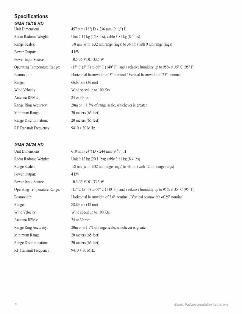
SpecificationsGMR 18/18 HDUnit Dimensions: 457 mm (18") D x 236 mm (9 1/4
.") H
Radar Radome Weight: Unit 7.17 kg (15.8 lbs); cable 3.81 kg (8.4 lbs)
Range Scales: 1/8 nm (with 1/32 nm range rings) to 36 nm (with 9 nm range rings)
Power Output: 4 kW
Power Input Source: 10.5-35 VDC 33.5 W
Operating Temperature Range: -15° C (5° F) to 60° C (140° F), and a relative humidity up to 95% at 35° C (95° F)
Beamwidth: Horizontal beamwidth of 5° nominal / Vertical beamwidth of 25° nominal
Range: 66.67 km (36 nm)
Wind Velocity: Wind speed up to 100 Kts
Antenna RPMs: 24 or 30 rpm
Range Ring Accuracy: 20m or ± 1.5% of range scale, whichever is greater
Minimum Range: 20 meters (65 feet)
Range Discrimination: 20 meters (65 feet)
RF Transmit Frequency: 9410 ± 30 MHz
GMR 24/24 HDUnit Dimensions: 610 mm (24") D x 244 mm (9 5/8") H
Radar Radome Weight: Unit 9.12 kg (20.1 lbs); cable 3.81 kg (8.4 lbs)
Range Scales: 1/8 nm (with 1/32 nm range rings) to 48 nm (with 12 nm range rings)
Power Output: 4 kW
Power Input Source: 10.5-35 VDC 33.5 W
Operating Temperature Range: -15° C (5° F) to 60° C (140° F), and a relative humidity up to 95% at 35° C (95° F)
Beamwidth: Horizontal beamwidth of 3.6° nominal / Vertical beamwidth of 25° nominal
Range: 88.89 km (48 nm)
Wind Velocity: Wind speed up to 100 Kts
Antenna RPMs: 24 or 30 rpm
Range Ring Accuracy: 20m or ± 1.5% of range scale, whichever is greater
Minimum Range: 20 meters (65 feet)
Range Discrimination: 20 meters (65 feet)
RF Transmit Frequency: 9410 ± 30 MHz
Garmin Radome Installation Instructions 7
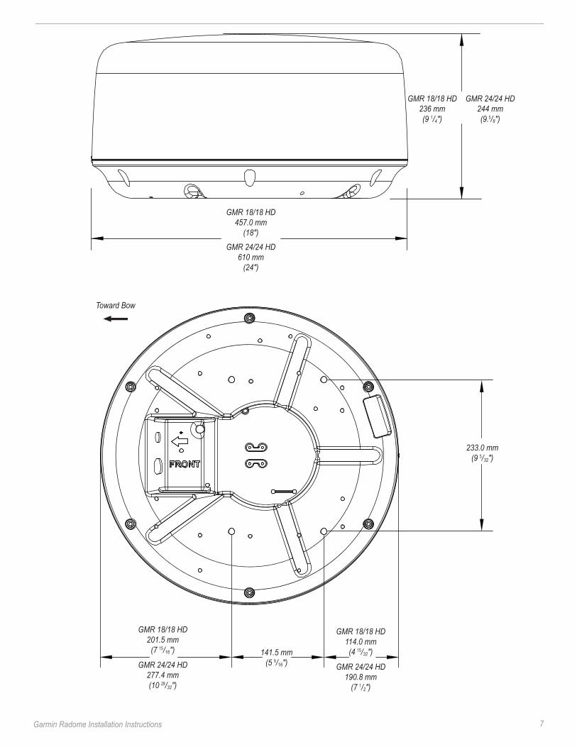
Toward Bow
GMR �8/�8 HD ��6 mm (9 1/4")
GMR �4/�4 HD �44 mm(9.5/8")
GMR �8/�8 HD 457.0 mm
(�8")
GMR �4/�4 HD 6�0 mm
(�4")
���.0 mm (9 5/��")
�4�.5 mm (5 9/�6")
GMR �8/�8 HD �0�.5 mm
(7 15/�6")
GMR �4/�4 HD �77.4 mm (�0 29/��")
GMR �8/�8 HD ��4.0 mm (4 15/��")
GMR �4/�4 HD �90.8 mm
(7 1/�")
8 Garmin Radome Installation Instructions
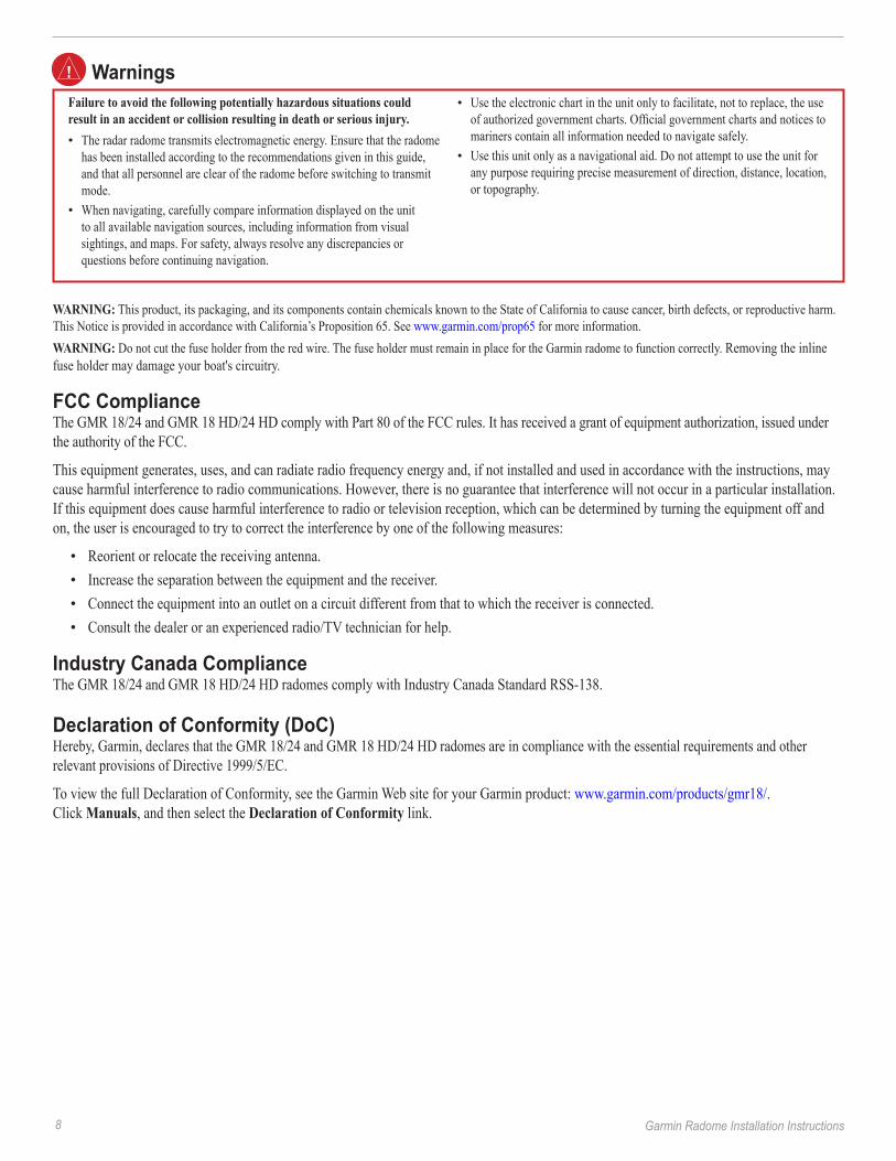
WarNING: This product, its packaging, and its components contain chemicals known to the State of California to cause cancer, birth defects, or reproductive harm. This Notice is provided in accordance with California’s Proposition 65. See www.garmin.com/prop65 for more information.WarNING: Do not cut the fuse holder from the red wire. The fuse holder must remain in place for the Garmin radome to function correctly. Removing the inline fuse holder may damage your boat's circuitry.
FCC ComplianceThe GMR 18/24 and GMR 18 HD/24 HD comply with Part 80 of the FCC rules. It has received a grant of equipment authorization, issued under the authority of the FCC.
This equipment generates, uses, and can radiate radio frequency energy and, if not installed and used in accordance with the instructions, may cause harmful interference to radio communications. However, there is no guarantee that interference will not occur in a particular installation. If this equipment does cause harmful interference to radio or television reception, which can be determined by turning the equipment off and on, the user is encouraged to try to correct the interference by one of the following measures:
Reorient or relocate the receiving antenna.Increase the separation between the equipment and the receiver. Connect the equipment into an outlet on a circuit different from that to which the receiver is connected.Consult the dealer or an experienced radio/TV technician for help.
Industry Canada ComplianceThe GMR 18/24 and GMR 18 HD/24 HD radomes comply with Industry Canada Standard RSS-138.
Declaration of Conformity (DoC)Hereby, Garmin, declares that the GMR 18/24 and GMR 18 HD/24 HD radomes are in compliance with the essential requirements and other relevant provisions of Directive 1999/5/EC.
To view the full Declaration of Conformity, see the Garmin Web site for your Garmin product: www.garmin.com/products/gmr18/. Click Manuals, and then select the Declaration of Conformity link.
••••
Failure to avoid the following potentially hazardous situations could result in an accident or collision resulting in death or serious injury.
The radar radome transmits electromagnetic energy. Ensure that the radome has been installed according to the recommendations given in this guide, and that all personnel are clear of the radome before switching to transmit mode.When navigating, carefully compare information displayed on the unit to all available navigation sources, including information from visual sightings, and maps. For safety, always resolve any discrepancies or questions before continuing navigation.
•
•
Use the electronic chart in the unit only to facilitate, not to replace, the use of authorized government charts. Official government charts and notices to mariners contain all information needed to navigate safely.Use this unit only as a navigational aid. Do not attempt to use the unit for any purpose requiring precise measurement of direction, distance, location, or topography.
•
•
Warnings
Garmin Radome Installation Instructions 9
Software License AgreementBY USING THE GARMIN RADOME, YOU AGREE TO BE BOUND BY THE TERMS AND CONDITIONS OF THE FOLLOWING SOFTWARE LICENSE AGREEMENT. PLEASE READ THIS AGREEMENT CAREFULLY.
Garmin grants you a limited license to use the software embedded in this device (the “Software”) in binary executable form in the normal operation of the product. Title, ownership rights, and intellectual property rights in and to the Software remain in Garmin.
You acknowledge that the Software is the property of Garmin and is protected under the United States of America copyright laws and international copyright treaties. You further acknowledge that the structure, organization, and code of the Software are valuable trade secrets of Garmin and that the Software in source code form remains a valuable trade secret of Garmin. You agree not to decompile, disassemble, modify, reverse assemble, reverse engineer, or reduce to human readable form the Software or any part thereof or create any derivative works based on the Software. You agree not to export or re-export the Software to any country in violation of the export control laws of the United States of America.
Limited WarrantyAll Garmin marine radomes and open array radomes are warranted to be free from defects in materials or workmanship for two years from the date of purchase. Within this period, Garmin will, at its sole option, repair or replace any components that fail in normal use. Such repairs or replacement will be made at no charge to the customer for parts or labor, provided that the customer shall be responsible for any transportation cost. This warranty does not cover failures due to abuse, misuse, accident, or unauthorized alteration or repairs.
THE WARRANTIES AND REMEDIES CONTAINED HEREIN ARE EXCLUSIVE AND IN LIEU OF ALL OTHER WARRANTIES EXPRESS, IMPLIED, OR STATUTORY, INCLUDING ANY LIABILITY ARISING UNDER ANY WARRANTY OF MERCHANTABILITY OR FITNESS FOR A PARTICULAR PURPOSE, STATUTORY OR OTHERWISE. THIS WARRANTY GIVES YOU SPECIFIC LEGAL RIGHTS, WHICH MAY VARY FROM STATE TO STATE.
IN NO EVENT SHALL GARMIN BE LIABLE FOR ANY INCIDENTAL, SPECIAL, INDIRECT, OR CONSEQUENTIAL DAMAGES, WHETHER RESULTING FROM THE USE, MISUSE, OR INABILITY TO USE THIS PRODUCT OR FROM DEFECTS IN THE PRODUCT. Some states do not allow the exclusion of incidental or consequential damages, so the above limitations may not apply to you. Garmin retains the exclusive right to repair or replace the unit or software or offer a full refund of the purchase price at its sole discretion. SUCH REMEDY SHALL BE YOUR SOLE AND EXCLUSIVE REMEDY FOR ANY BREACH OF WARRANTY.
To obtain warranty service, contact your local Garmin authorized dealer or call Garmin Product Support for shipping instructions and an RMA tracking number. Securely pack the unit and a copy of the original sales receipt, which is required as the proof of purchase for warranty repairs. Write the tracking number clearly on the outside of the package. Send the unit, freight charges prepaid, to any Garmin warranty service station.
online auction Purchases: Products sold through online auctions are not eligible for rebates or other special offers from Garmin. Online auction confirmations are not accepted for warranty verification. To obtain warranty service, an original or copy of the sales receipt from the original retailer is required. Garmin will not replace missing components from any package purchased through an online auction.
International Purchases: A separate warranty is provided by international distributors for units purchased outside the United States. This warranty is provided by the local in-country distributor and this distributor provides local service for your unit. Distributor warranties are only valid in the area of intended distribution. Units purchased in the United States or Canada must be returned to the Garmin service center in the United Kingdom, the United States, Canada, or Taiwan for service.
Garmin International, Inc. Garmin (Europe) Ltd. Garmin Corporation 1200 East 151st Street, Liberty House No. 68, Jangshu 2nd Road, Olathe, Kansas 66062, USA Hounsdown Business Park, Shijr, Taipei County, Taiwan Tel. (913) 397-8200 or Southampton, Hampshire, SO40 9RB UK Tel. 886/2.2642.9199 (800) 800-1020 Tel. +44 (0) 870.8501241 (outside the UK) Fax 886/2.2642.9099 Fax (913) 397-8282 0808.2380000 (within the UK) Fax +44 (0) 870.8501251
For the latest free software updates (excluding map data) throughout the life of your Garmin products, visit the Garmin Web site at www.garmin.com.
© 2007-2008 Garmin Ltd. or its subsidiaries
Garmin International, Inc. 1200 East 151st Street, Olathe, Kansas 66062, USA
Garmin (Europe) Ltd. Liberty House, Hounsdown Business Park, Southampton, Hampshire, SO40 9RB UK
Garmin Corporation No. 68, Jangshu 2nd Road, Shijr, Taipei County, Taiwan
www.garmin.com
Part Number 190-00831-02 Rev. C