gmtifs: the adaptive optics beam steering mirror for the gmt integral-field spectrograph ·...
TRANSCRIPT

GMTIFS: The Adaptive Optics Beam Steering Mirror for the GMT Integral-Field Spectrograph
J. Davies, G. Bloxham, R. Boz, D. Bundy, B. Espeland, B. Fordham, J. Hart, N. Herrald, J. Nielsen, R.
Sharp, A. Vaccarella, C. Vest, P. J. Young. Research School of Astronomy & Astrophysics, The Australian National University, Mount Stromlo Observatory, Cotter Road, Weston Creek, ACT 2611, Australia.
ABSTRACT
To achieve the high adaptive optics sky coverage necessary to allow the GMT Integral-Field Spectrograph (GMTIFS) to access key scientific targets, the on-instrument adaptive-optics wavefront-sensing (OIWFS) system must patrol the full 180 arcsecond diameter guide field passed to the instrument. The OIWFS uses a diffraction limited guide star as the fundamental pointing reference for the instrument. During an observation the offset between the science target and the guide star will change due to sources such as flexure, differential refraction and non-sidereal tracking rates. GMTIFS uses a beam steering mirror to set the initial offset between science target and guide star and also to correct for changes in offset. In order to reduce image motion from beam steering errors to those comparable to the AO system in the most stringent case, the beam steering mirror is set a requirement of less than 1 milliarcsecond RMS. This corresponds to a dynamic range for both actuators and sensors of better than 1/180,000.
The GMTIFS beam steering mirror uses piezo-walk actuators and a combination of eddy current sensors and interferometric sensors to achieve this dynamic range and control. While the sensors are rated for cryogenic operation, the actuators are not. We report on the results of prototype testing of single actuators, with the sensors, on the bench and in a cryogenic environment. Specific failures of the system are explained and suspected reasons for them. A modified test jig is used to investigate the option of heating the actuator and we report the improved results. In addition to individual component testing, we built and tested a complete beam steering mirror assembly. Testing was conducted with a point source microscope, however controlling environmental conditions to less than 1 micron was challenging. The assembly testing investigated acquisition accuracy and if there was any un-sensed hysteresis in the system. Finally we present the revised beam steering mirror design based on the outcomes and lessons learnt from this prototyping.
1 INTRODUCTION
The Giant Magellan Telescope Integral Field Spectrograph and Imager, GMTIFS, is scheduled to see first light at the GMT alongside adaptive-optics commissioning in 2022. The instrument couples to the folded F=8 Gregorian focus of the GMT and provides a 20" x 20" field-of-view diffraction-limited broad-band imager and rectangular integral-field spectrograph with four interchangeable scales to sample both the diffraction limit (6 & 12 mas spaxels) and provide high sensitivity to low surface brightness extended sources (25 & 50 mas spaxels). The instrument concept entered into the Preliminary Design Phase in September 2013 at the Australian National University (ANU) and builds on the combined heritage of the Gemini Near-IR Integral-Field Spectrograph [1], [2] and Gemini South Adaptive Optics Imager [3], [4] systems delivered by the design team for the current generation of flagship AO systems.
The GMTIFS instrument consists of a large cryostat housing a three layered optical table as displayed in Figure 1. Light enters the cryostat at the central layer through a tilted dichroic window and optical compensating plate and comes to focus at the science pick-off mirror at the telescope focus which folds out the science field and passes the surrounding guide field to the On-Instrument Wavefront Sensor (OIWFS) via the Beam Steering Mirror (BSM). The upper level houses the optical relay containing the cold-stop and atmospheric dispersion corrector as well as the Imager optics and the IFS anamorphic projection optics. This layer also has the associated science selector dichroic suite which defines the
Advances in Optical and Mechanical Technologies for Telescopes and Instrumentation II, edited by Ramón Navarro, James H. Burge, Proc. of SPIE Vol. 9912, 991217
© 2016 SPIE · CCC code: 0277-786X/16/$18 · doi: 10.1117/12.2231560
Proc. of SPIE Vol. 9912 991217-1
Downloaded From: http://proceedings.spiedigitallibrary.org/ on 02/01/2017 Terms of Use: http://spiedigitallibrary.org/ss/termsofuse.aspx

observational wavelength passed to the spectrograph or imager. The lower layer supports the integral-field spectrograph and the on-instrument wavefront sensor.
By virtue of a light weight but stiff construction, all optical components are supported from this common optical table, minimising internal flexure and limiting differential motion between the OIWFS and the science detectors. The central layer of the optical table, the cavity formed within the table’s cross-braced structure, houses the BSM mechanism responsible for acquiring a guide star and passing it to the OIWFS. The concept and design criteria for this system forms the body of this presentation, but first we consider the operational and scientific requirements placed on such a system.
Figure 1. The chamber layouts for the three levels of the GMTIFS optics.
1.1 GMTIFS AO Feed
The science field is fed to GMTIFS from the Adaptive Secondary Mirror (ASM) with AO correction derived from either the on-axis Natural Guide Star AO (NGSAO [5]) or the off-axis Laser Tomography Adaptive Optics (LTAO [6]) system1. Wavefront correction in NGSAO is derived by an optical system mounted externally to the GMTIFS cryostat along with the laser wavefront sensor constellation required of LTAO. Both systems require an On-Instrument Wave Front Sensor (OIWFS), coupled tightly to the spectrograph optical table within the cryostat. When performing NGSAO observations a slow differential flexure compensation is required, while in LTAO mode the OIWFS provides the essential fast tip-tilt correction (not sensed by the laser system) along with truth and focus calibrations.
1.2 Sky Coverage and Guide Star Acquisition
The current generation of astronomical AO systems, deployed largely on 8 m class telescopes, have suffered to some degree due to poor sky coverage. The need for a bright stellar source close to the science target restricts telescope pointing and prevents many key science targets from benefiting from AO observations, particularly in important legacy deep fields (selected in part for their low stellar density). Sky coverage is significantly increased with the introduction of laser guide stars, which in essence place an artificial star onto the science target. However laser beacons provide only high order correction, and are insensitive to tip-tilt (due to the double-pass of the laser light through the atmospheric turbulence.
1 Additionally, recent analysis indicates sufficient image correction (FWHM ~ 200 mas) will be possible with Ground Layer Adaptive Optics correction (GLAO) in the K-band to deliver scientifically interesting observations of extended sources during early commissioning phases of the AO system.
Proc. of SPIE Vol. 9912 991217-2
Downloaded From: http://proceedings.spiedigitallibrary.org/ on 02/01/2017 Terms of Use: http://spiedigitallibrary.org/ss/termsofuse.aspx
A key concern in developing the GMTIFS system has been to ensure sufficient access to stars bright enough to perform this correction. Sky coverage is dictated not only by the limiting sensitivity of the wavefront sensing system (setting the faintest photon return, and hence star magnitude, which allows sufficient sensing speed) but also the field of view surrounding a given science target from which suitable stars can be drawn. While angular isoplanatism degrades AO performance with increasing angular separation between science target and AO guide stars, simulations show correction can be achieved for guides stars at a radius of < 90", and hence the GMTIFS design allows the OIWFS access to stars drawn from across the 180" diameter field of view of the folded Gregorian focal plane of GMT. This sensitivity and field of view will allow GMT/GMTIFS to deliver > 90% sky coverage for low surface brightness LTAO mode and also to deliver exquisite image quality for a smaller fraction of the sky (> 30%) with ideal guide stars.
The F=8 focal plane of the GMT delivers a plate scale of ~ 1 arcsec mm-1 and hence the pick-off system for OIWFS guide star selection must access a field 180 mm in diameter in order to access the full available guide field. The requirement to deliver diffraction limited image quality over exposure times of 900 - 1800 seconds duration dictates that the star pick-off be held on the OIWFS with a positional accuracy of 1 µm in the focal plane. Field derotation is principally provided to GMTIFS by the GMT Gregorian Instrument Rotator. However, for Angular Differential Imaging observations and other none-sidereal tracking rates the OIWFS feed must perform the differential tracking. Furthermore, since the guide field is not corrected for differential refraction or dispersion in the proposed OIWFS design this correction must be performed by the BSM. This degree of stability was considered challenging for a deployable pick-off arm system. Instead the GMTIFS has elected to direct the guide star onto the OIWFS via a Beam Steering Mirror located behind the focal plane, with the 20" x 20" science field redirected by a science fold in the centre of the guide field at the telescope focal plane. A concentric BSM provides the required performance which a simple, compact and rigid structure with the mirror body tipped and tilted about its own centroid.
2 POSITIONAL REQUIREMENTS
The guide star must be steered to the OIWFS such that it does not degrade the AO corrected PSF due to tip-tilt motion introduced by the beam steering system. This is taken to mean 10% of the Rayleigh-criterion. For λ = 1 µm and a focal ratio of F = 8, this becomes a positional tolerance of ℎ = 1.22 (1)
With the focal plane and BSM separated by l = 1520 mm this becomes an angular tip-tilt resolution of θ = = 0.33 × 10 (0.068 ) (2)
For a three-strut mount with a pitch of r = 100 mm (retaining a compact design with sufficient mechanical clearances) and assuming this error is the quadrature sum of the mount strut individual positional errors, we find the precision required in positioning each strut actuator is = √ θ = √ ℎ (3)
The maximum displacement, at the extreme edge of the 180 mm diameter guide field, is h = 90 mm, hence the maximum steering angle is θ = = 0.030 (1.7°) (4)
leading to a maximum actuator travel (for pitch of r = 100 mm) of = = 3 (5)
Hence the resolution of the system, with an angular range of 2θ = 0.060 rad, requires a dynamic range of
Proc. of SPIE Vol. 9912 991217-3
Downloaded From: http://proceedings.spiedigitallibrary.org/ on 02/01/2017 Terms of Use: http://spiedigitallibrary.org/ss/termsofuse.aspx
2 = 182400⁄ (6)
In addition to guide star acquisition, the OIWFS system will also be required to map out on-source dither patterns for high precision observations. Many principle science targets will provide insufficient signal in individual observation frames for accurate registration of data during post processing and data will require combination from multiple such observations, potentially spread across multiple visits to the source. Recording the high precision relative offsets for the dither pattern observation allows accurate registration preventing image blurring.
3 BEAM STEERING MIRROR
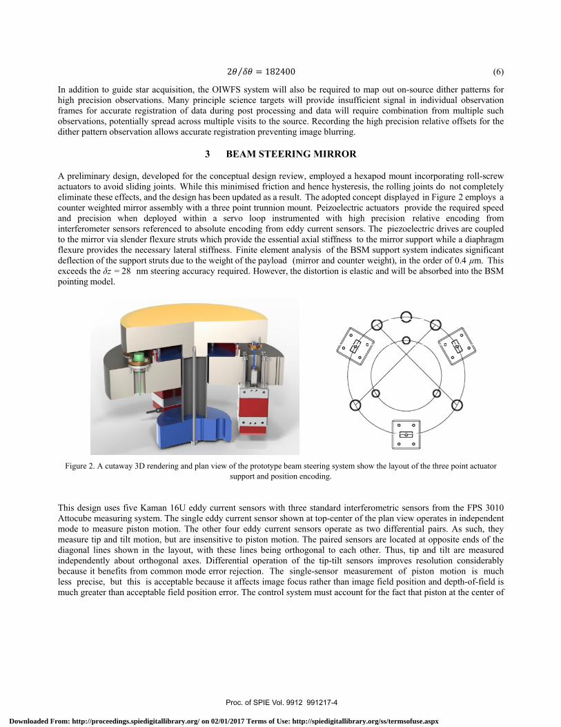
A preliminary design, developed for the conceptual design review, employed a hexapod mount incorporating roll-screw actuators to avoid sliding joints. While this minimised friction and hence hysteresis, the rolling joints do not completely eliminate these effects, and the design has been updated as a result. The adopted concept displayed in Figure 2 employs a counter weighted mirror assembly with a three point trunnion mount. Peizoelectric actuators provide the required speed and precision when deployed within a servo loop instrumented with high precision relative encoding from interferometer sensors referenced to absolute encoding from eddy current sensors. The piezoelectric drives are coupled to the mirror via slender flexure struts which provide the essential axial stiffness to the mirror support while a diaphragm flexure provides the necessary lateral stiffness. Finite element analysis of the BSM support system indicates significant deflection of the support struts due to the weight of the payload (mirror and counter weight), in the order of 0.4 µm. This exceeds the δz = 28 nm steering accuracy required. However, the distortion is elastic and will be absorbed into the BSM pointing model.
Figure 2. A cutaway 3D rendering and plan view of the prototype beam steering system show the layout of the three point actuator
support and position encoding.
This design uses five Kaman 16U eddy current sensors with three standard interferometric sensors from the FPS 3010 Attocube measuring system. The single eddy current sensor shown at top-center of the plan view operates in independent mode to measure piston motion. The other four eddy current sensors operate as two differential pairs. As such, they measure tip and tilt motion, but are insensitive to piston motion. The paired sensors are located at opposite ends of the diagonal lines shown in the layout, with these lines being orthogonal to each other. Thus, tip and tilt are measured independently about orthogonal axes. Differential operation of the tip-tilt sensors improves resolution considerably because it benefits from common mode error rejection. The single-sensor measurement of piston motion is much less precise, but this is acceptable because it affects image focus rather than image field position and depth-of-field is much greater than acceptable field position error. The control system must account for the fact that piston at the center of
Proc. of SPIE Vol. 9912 991217-4
Downloaded From: http://proceedings.spiedigitallibrary.org/ on 02/01/2017 Terms of Use: http://spiedigitallibrary.org/ss/termsofuse.aspx

the system is a function of piston measured by the independent sensor and the tip-tilt measured by the differential sensors. There is also some mean-position displacement at the differential sensor pairs that accompanies tip-tilt because the pair axes are offset from the mirror center, but the system is insensitive to this.
The three interferometric sensors are mounted inboard of the actuators and eddy current sensors. The mirrors they use take the form of aluminium alloy posts with diamond machined ends that are screwed into the mirror body. There are three corresponding holes in the trunnion diaphragm to allow passage of the interferometer beams. They also allow the post ends to pass though the diaphragm as the mirror tips and tilts. The separation between mirrors and sensors can thereby be made small to minimize lateral displacement of the return beam as it re-enters the sensor. This lateral displacement is likewise reduced by the smaller pitch circle radius of the interferometric sensor system. The consequently smaller range of movement that they measure is acceptable because these sensors have sub-nanometer resolution. The aim with this configuration is to achieve adequate resolution from the eddy current sensors alone, in which case the interferometric sensors function only as test devices. Should this aim not be achieved, the eddy current sensors would be used for absolute calibration of the incremental interferometric sensors in a system that requires both sensor types.
Off-the-shelf (OTS) beam steering mirror assemblies were considered prior to the development of the current design. However, these OTS units were limited in suitability for several reason, including: non-cryogenic and high vacuum operation; limited load capacity; and limited resolution dynamic range.
3.1 Piezoelectric Linear Actuators
The linear motion of the three positional struts are provided by Physik Instrumente (PI) N-216.20 Nexline piezo linear actuators. While these devices are not rated for cryogenic operations (~100 K for GMTIFS), this will be addressed by local heating of the individual actuators.
There are several other known issues that had to be addressed in BSM design and testing. These include: the load capacity of the actuator in nano step mode is reduced to approximately 60% of that in full step mode; the minimum operational temperature is only -40°C (~ 233 K); the actuators are unguided and are subject to mechanical crosstalk that is observed as off-axis wobble; and there is an observed tendency to back step across the piezo step transitions. The reduced load capacity in nano step mode is not considered to be an issue due to the high load capacity of the actuator. Even at the reduced operating temperature there is still sufficient load capacity. The minimum operating temperature can be addressed and is discussed below. The mechanical crosstalk is not considered to be a significant issue because any lateral actuator motion will be constrained by the struts in the BSM assembly and is corrected by the closed loop control system. Inter-step backward displacements will be eliminated by working with the manufacturer to optimize the actuator for reduced temperature operation.
Cryogenic operation can be challenging for piezoelectric actuators. With a reduction in temperature comes a reduction in the clamp and shear stack displacement which subsequently reduces the actuators step size and ramp velocity. Additionally, operation in nano step mode at lower temperature can increase actuator wear and reduce its operational life. Remedial measures that are considered to compensate for the performance degradation at lower temperatures might include using higher drive voltages; drive waveform optimization and the adjustment (reduction) of the actuator preload.
The actuator piezo stacks operate at voltages up to ±250 V and, as such, they are at risk of arcing or voltage breakdown under certain conditions. The particular condition in this case is vacuum operation. At partial vacuum conditions can exist that promote voltage breakdown across the piezo stacks. The obvious control for this is to ensure that the actuators are not energised while performing a pump down prior to cryogenic operation
Proc. of SPIE Vol. 9912 991217-5
Downloaded From: http://proceedings.spiedigitallibrary.org/ on 02/01/2017 Terms of Use: http://spiedigitallibrary.org/ss/termsofuse.aspx

3.2 Absolute Displacement Encoding via Eddy Current Sensors
Absolute position encoding will be performed with a 3-axis differential sensor system, consisting of three pairs of Kaman DIT-5200-16U eddy current sensors (ECS). As described above, the prototype BSM had two orthogonal differential pairs of sensors measuring tip-tilt, while a single-ended sensor measured piston. The required head diameter for the sensors increases with range to target. The target surface, in this instance the aluminium mirror body itself, must be flat and unobstructed over a diameter that is approximately x3 the head diameter. These constraints are easily accommodated with the sensors selected and are fully consistent with the required range of mirror motion. The sensors are UHV and cryo-rated.
The stringent positioning tolerance of the BSM under operational conditions (28 nm position accuracy) is near the limit of specification for the chosen sensors and hence the final accuracy of the system may not be achieved with the eddy current system alone. For this reason a secondary high precision relative position sensor array, will be employed to ensure compliance. Both systems were prototyped as part of development of the piezoelectric actuator verification test plan. The results obtained from the tests described below indicate, however, that the eddy current sensors will provide the necessary resolution.
The eddy current sensors are subject to measurement non-linearity due to inappropriate installation and operating temperature. The installation-induced non-linearity is typically caused by side loading of the sensor by adjacent metal structures. Suitable clearance to the sides and rear of each sensor is required to avoid this problem. Temperature induced non-linearity is very significant at the ~ 100 K cryogenic operating temperature due to the effect on the sensor coil impedance. Fortunately, both of these sources of non-linearity can be addressed by calibration of the assembly at the operating temperature and applying linearization coefficients to the actuator controller.
These sensors are also subject to electrical noise and interference. The sources of noise in this case would include mains-borne interference, electronic noise in the sensor modules, and sensor crosstalk. External interference was addressed with appropriate earthing, shielding and suppression. The common mode rejection of the differential sensor configuration removed most of this noise and interference. However, crosstalk was found to be an issue when more than one sensor electronics module was operating. This crosstalk was due to cross-coupling of the RF excitation signals used by the sensors to generate the eddy current fields in the target and manifest as a beat frequency in the displacement measurements.
3.3 Relative Displacement Encoding via Interferometric Sensors
High precision (sub-nm) relative encoding will be provided by an Attocube FPS3010 3-channel interferometric displacement sensor system. These sensors provide no absolute position data, this being derived from the eddy current sensor system, but ensure the system reaches the required relative displacement accuracy. Tracking speeds of ≤ 1 m s−1 are achievable and they also provide the ideal sensor system with which to calibrate the performance of the piezoelectric actuator system under operational conditions during prototyping.
Mirror tilt is limited by the allowed separation between the return beam and the receiving aperture of the interferometer sensor. This limits the maximum design separation between the sensor and target. The displacement range required for the mirror is 6 mm for a 100 mm pitch diameter, consistent with the maximum separation allowed by the devices. Consequently the interferometric sensors are mounted on a reduced pitch and as close as possible to the target area on the mirror back surface. The relative precision of the sensor system comfortably exceeds that required. Fortunately, the interferometric sensors are immune to electrical interference and are not affected by cryogenic temperature operation.
3.4 Beam Steering Mirror Reacquisition and Flexure Tests
The aim of these tests was to demonstrate that a guide star can be acquired and reacquired to the 1 μm specification, irrespective of attitude. The test utilizes the BSM flexure rig to mount a point source microscope (PSM) on axis with the
Proc. of SPIE Vol. 9912 991217-6
Downloaded From: http://proceedings.spiedigitallibrary.org/ on 02/01/2017 Terms of Use: http://spiedigitallibrary.org/ss/termsofuse.aspx

BSM, where the PSM provides a representative guide star at the nominal focal plane. The test configuration shown in Figure 3, below, displays the flexure test rig. The BSM assembly is interfaced to the controller rack that includes the PI E-712 piezo controller; the Kaman DIT-5200 and SMT-9700 eddy current sensor systems; and the Attocube FPS3010 interferometer system. The PSM and inertial system (INS) are controlled by their respective software applications on a separate laptop.
Figure 3. Overview of Axial Mechanism Flexure Configuration
The following images display the flexure test assembly on the optical bench. In Figure 4 the flexure rig is shown resting on two roller block assemblies on the optical bench with the BSM actuator and sensor cabling interfaced to the controller rack in the foreground.
3.4.1 Point Source Microscope Re-Acquisition
The aim of this test was to determine the stability and repeatability of the BSM to closed loop commands. The performance was to be measured using the PSM Align software. The re-acquisition process required the BSM to be driven off axis in a direction θ by the equivalent of 1 mm of actuator displacement; this is approximately 30 mm in the field. The BSM was then driven back to the datum position for re-acquisition.
The field offset was measured by analyzing the beam centroid at the beginning and end of each sequence. This measurement was averaged over approximately 10 seconds of each video clips. The direction angles were θ = 0°, 90°, 180°, 270° and the re-acquisition at each angle was performed three times to determine the RMS offset. Successful completion of this test would demonstrated the ability to: acquire a guide star; move the BSM off target; and reacquire the guide star to better than 1μm.
The PSM beam (the ‘guide star’) was successfully acquired with the X acquisition position maintained to within less than 0.5 µm RMS; the Y acquisition position was maintained to within ~ 1.7 µm RMS. The primary reason for the for the higher Y jitter measurements is most likely due to the high level of coupling from the piston sensor ECS (see below for further discussion). In each case of the 0°, 90°, 180° and 270° sequences the PSM beam was moved in closed loop approximately 30 mm off target and returned. The PSM beam typically returned to a position within ±1.0 µm of the target position in most cases. In the case of the X measurements in each of the 0°, 90°, 180° and 270° sequences, the first returns were significantly higher at ±1.5 to ±2.0 µm. Subsequent returns were typically less than ±0.5 µm. As stated
Proc. of SPIE Vol. 9912 991217-7
Downloaded From: http://proceedings.spiedigitallibrary.org/ on 02/01/2017 Terms of Use: http://spiedigitallibrary.org/ss/termsofuse.aspx

/c:y--
above, this trend was not evident with the Y measurements however, with values ranging over 0.0 to ±2.0 µm, but typically less than ±0.5 µm.
Figure 4. BSM reacquisition and flexure test assembly setup
Figure 5. Beam Steering Mirror installation Figure 6. Point Source Microscope installation
3.4.1.1 Loss of Interferometric Sensor Return Signal
The interferometric sensors displayed anomalous behaviour throughout the reacquisition tests involving the loss of return signal in the 0°, 90° and 180° reacquisition sequences. Throughout the 0° and 180° sequences in particular, the signal loss triggered error conditions at specific rotation angles. The error condition occurred at an angular rotation equivalent to approximately 0.23°. The error condition continues as the rotation angle increases to a maximum of approximately 0.57° and until the mirror rotates back to the equivalent angular rotation of 0.23°. This error pattern is repeated throughout the full sequence of three tilt motions. The alignment tolerance of the collimators used with the interferometer should tolerate up to at least ±2° of misalignment. Further investigation of this issue was conducted. This investigation showed that angular tolerance of the target degraded quickly with lateral displacement of the target. The
Proc. of SPIE Vol. 9912 991217-8
Downloaded From: http://proceedings.spiedigitallibrary.org/ on 02/01/2017 Terms of Use: http://spiedigitallibrary.org/ss/termsofuse.aspx

results of this investigation included a recommendation to employ a newly-available collimator that allowed for a greater angular rotation.
3.4.2 Beam Steering Mirror Flexure Test
The aim of this test was to confirm that mechanism flexure is elastic and the design mitigates hysteresis. The flexure testing was performed about the optical axis of the beam steering mirror and will detect any component of sag or slippage at mechanical interfaces. To achieve this the BSM was operated in closed-loop mode, but only in the sense of maintaining the position of the mirror cell against the BSM base, which also forms the reference for both the eddy current and interferometric sensors. Only hysteresis that is undetected by the sensors is of concern; hysteresis that is detected by the sensors is corrected by the closed loop control system.
The BSM assembly was initially at the datum position for the PSM. The control system simply holds the BSM at the same sensor position under closed loop control. The flexure rig was manually rotated from θ = 0˚ to θ = 90˚, 180°, 270° the using the inertial navigation sensor as reference. For each θ the flexure rig was then be rotated back to θ = 0˚. The mechanical stop was applied and the field offset determined from the PSM Align software package. This process was performed three times for each value of θ to determine the RMS offset. The test pass/fail criterial for this test is primarily judged by the absence of hysteresis when returning to the start position between gravity vector changes. This is derived from the relative position differences between each test sequence.
The results from each flexure motion showed that in most cases the RMS X values are less than 0.3 µm. By contrast, the RMS Y values are from 0.7 to 1.4 µm. The primary reason for the higher Y jitter measurements is most likely due to the high level of coupling from the piston sensor ECS (see below for further discussion). The relative position differences between the repeated motions range over 0.0 to ±4.6 µm with values typically less than ±1.0 µm. This indicates that the PSM beam typically returns to a position within ±1.0 µm of the target position in most cases. Flexure testing has demonstrated that the beam steering mirror is immune to hysteresis and can be simply be described by elastic deformation.
3.4.3 Eddy Current Sensor Coupling
It has been known from previous tests that cross-coupling of the ECS excitation signals represents a potential reduction in displacement measurement resolution. In those cases this coupling has been manageable. However, it was evident throughout this test process that the single-ended ECS introduced significant cross-coupled interference. This was not totally unexpected due to its proximity to the other ECS pairs. This interference was most likely responsible for significant closed loop jitter in the observed PSM return beam, particularly in the Y axis. It is recommended that the proposed final design for the BSM will use maximum separation and only differential pairs sensing equal and opposite displacement.
3.5 Single Heated Actuator Cryogenic Tests
A single locally-heated PI N-216.20 piezo actuator was tested in the Detector Test Facility (DTF). The actuator was maintained at 250 K (-23 °C) which is well above the recommended minimum operating temperature for the actuator of ~ 233 K (-40 °C). The cryostat cold work surface (CWS) was at 80 K. The primary goal was to establish a baseline cryogenic displacement performance for the actuator. The accuracy, step size and speed reduction with temperature are the principal parameters that were investigated. To ensure correct functionality of the tests, laboratory ambient bench testing was used to verify the motion control macros and control techniques for actuator operation prior to their installation in the Detector Test Facility (DTF). The heated PI N-216 piezo actuator test jig with two Kaman DIT-5200 eddy current sensor differential pairs, and two Attocube FPS3010 interferometric sensors were installed onto the DTF cold work surface (CWS) as shown in Figure 8 below.
Proc. of SPIE Vol. 9912 991217-9
Downloaded From: http://proceedings.spiedigitallibrary.org/ on 02/01/2017 Terms of Use: http://spiedigitallibrary.org/ss/termsofuse.aspx

The heated piezo actuator was connected externally to the PI E-712 controller system via a hermetic feedthrough assembly. The Kaman 16U eddy current sensor pairs connected externally to the 2-channel Kaman DIT-5200 electronics module via a hermetic SMA feedthrough. The Attocube laser interferometer collimator heads were connected internally via cryogenic optical fibers to an optical fiber hermetic feedthrough. Externally they connected via ambient fibers to two channels of the Attocube FPS3010 interferometer electronics module.
(a). (b).
Figure 7. The heated single actuator assembly is displayed in (a) showing the major components. The cutaway in (b) shows the hidden components.
Heating the actuator to 250 K, while the surrounding environment was < 100 K and a vacuum, only required 3.3 W. Eight thermocouples were installed to monitor the temperature of the actuator and adjacent structures. The thermocouples were connected via a DB9 hermetic thermocouple feedthrough to two external National Instruments thermocouple interfaces for the purpose of temperature logging.
The testing of the single actuator involved a number of test sequences controlled by command sequence macros on the PI E-712 controller PIMikroMove application and specifically developed C algorithms. The macro code was used to control the simpler displacement sequences that were designed to assess the actuators’ baseline step size and ramp rate in the full step and nano step displacement modes. The C algorithms were used to control the more complex tracking procedures that were used to assess the actuators’ finer tracking capacity in nano step mode at various update modes and rates.
The test procedures included: fixed rate open loop full step mode to determine the decrease in step size with a decrease in temperature; fixed rate closed loop full step mode to assess the slewing ability with a decrease in temperature to satisfy a requirement to acquire a guide star at the other side of the 180 mm BSM field in 30 seconds (200 µm/sec at the actuator); fixed rate closed loop nano step mode to assess the nano step ability with a decrease in temperature; fixed and
Load Spring
ECS 1A
ECS 2A
Piezo Actuator Heater Jacket
Heater Resistors
FPS2 (Lateral)
Limit Switches
Radiation Shield
Target Plate
ECS 1BFPS1 (Axial)
ECS 2B
Actuator rod
Proc. of SPIE Vol. 9912 991217-10
Downloaded From: http://proceedings.spiedigitallibrary.org/ on 02/01/2017 Terms of Use: http://spiedigitallibrary.org/ss/termsofuse.aspx
variable rate closed loop nano step tracking modes to assess the high resolution tracking capacity with a decrease in temperature and also with the presence of a 100 N load.
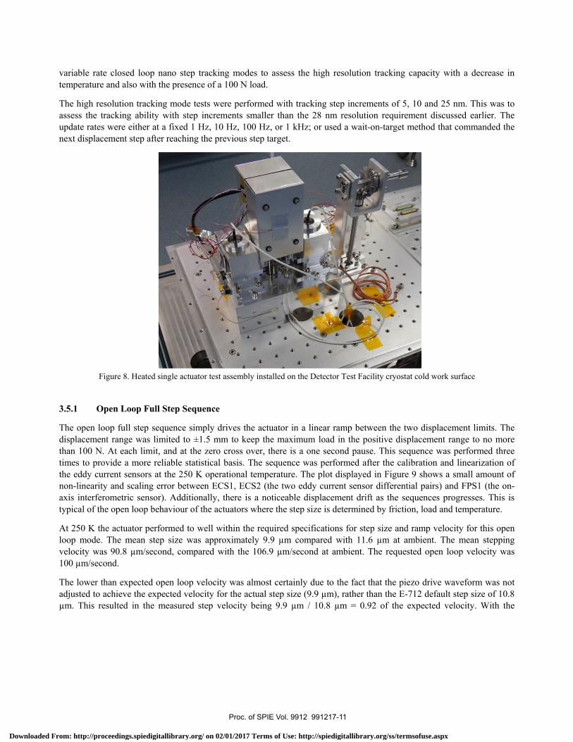
The high resolution tracking mode tests were performed with tracking step increments of 5, 10 and 25 nm. This was to assess the tracking ability with step increments smaller than the 28 nm resolution requirement discussed earlier. The update rates were either at a fixed 1 Hz, 10 Hz, 100 Hz, or 1 kHz; or used a wait-on-target method that commanded the next displacement step after reaching the previous step target.
Figure 8. Heated single actuator test assembly installed on the Detector Test Facility cryostat cold work surface
3.5.1 Open Loop Full Step Sequence
The open loop full step sequence simply drives the actuator in a linear ramp between the two displacement limits. The displacement range was limited to ±1.5 mm to keep the maximum load in the positive displacement range to no more than 100 N. At each limit, and at the zero cross over, there is a one second pause. This sequence was performed three times to provide a more reliable statistical basis. The sequence was performed after the calibration and linearization of the eddy current sensors at the 250 K operational temperature. The plot displayed in Figure 9 shows a small amount of non-linearity and scaling error between ECS1, ECS2 (the two eddy current sensor differential pairs) and FPS1 (the on-axis interferometric sensor). Additionally, there is a noticeable displacement drift as the sequences progresses. This is typical of the open loop behaviour of the actuators where the step size is determined by friction, load and temperature.
At 250 K the actuator performed to well within the required specifications for step size and ramp velocity for this open loop mode. The mean step size was approximately 9.9 µm compared with 11.6 µm at ambient. The mean stepping velocity was 90.8 µm/second, compared with the 106.9 µm/second at ambient. The requested open loop velocity was 100 µm/second.
The lower than expected open loop velocity was almost certainly due to the fact that the piezo drive waveform was not adjusted to achieve the expected velocity for the actual step size (9.9 µm), rather than the E-712 default step size of 10.8 µm. This resulted in the measured step velocity being 9.9 µm / 10.8 µm = 0.92 of the expected velocity. With the
Proc. of SPIE Vol. 9912 991217-11
Downloaded From: http://proceedings.spiedigitallibrary.org/ on 02/01/2017 Terms of Use: http://spiedigitallibrary.org/ss/termsofuse.aspx

o
1
Open Loop Full Step Sequence (A2, 100 umpa, 250 K, 100 N load) 140416 -1
20 40 60 80 100 120
Time (s(140 160 200
appropriate step size adjustment the velocity would have been more like 90.8 µm/second / 0.92 = 99.1 µm/second. These test values represent a ~ 15% reduction in open loop step size and velocity at 250 K, which is consistent with previous cryogenic test results.
Figure 9. Open loop full step sequence at 250 K
3.5.2 Closed Loop Full Step Slew Sequence
This sequence is used to provide initial calibration of the eddy current sensors. The actuator is commanded to perform a constant linear ramp between the two displacement limits in order to collect calibration data. This data is subsequently used to generate polynomial coefficients that are applied to the actuator controller.
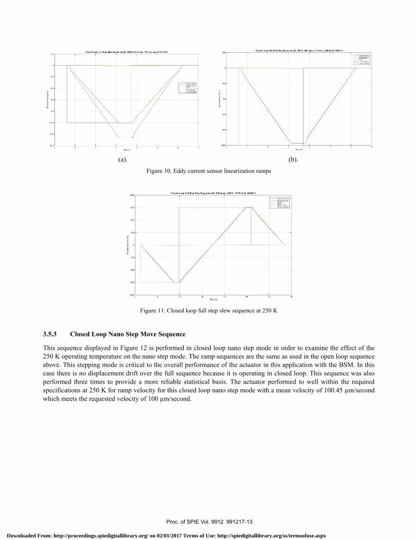
Figure 10(a) below displays a plot showing the significant scaling error between the two eddy current sensor differential pairs (ECS1 and ECS2) and the on-axis interferometer measurement (FPS1) with the actuator at 250 K. The eddy current sensors, however, are at closer to 100 K since they are mounted to the base of the actuator assembly that is sitting on the cold work surface which is at 80 K. As a result the eddy current sensors are under-reading by approximately 20%. Figure 10(b) displays a linearized plot after the application of the linearization coefficients in the controller.
The other requirement for this test sequence is to confirm that the actuator is capable of slewing the BSM across the 180 mm optical field in 30 seconds at the 250 K operational temperature. This requires a slew rate of 200 µm/second at the actuator.
The displacement range for the closed loop full step slew sequence displayed in Figure 11 below was limited to ±1.5 mm to keep the maximum load in the positive displacement range to no more than 100 N. There is a small amount of non-linearity observed between ECS1, ECS2 and FPS1. This is most likely due to the off-axis drift of the actuator rod.
The actuator performed to well within the required specifications at 250 K for ramp velocity for this closed loop full step mode with a mean slew velocity of 200.1 µm/second which meets the minimum acquisition slew requirement of 200 µm/second.
Proc. of SPIE Vol. 9912 991217-12
Downloaded From: http://proceedings.spiedigitallibrary.org/ on 02/01/2017 Terms of Use: http://spiedigitallibrary.org/ss/termsofuse.aspx
am_
Tn. Eel
o
laid b_N .......040
(a). (b).
Figure 10. Eddy current sensor linearization ramps
Figure 11. Closed loop full step slew sequence at 250 K
3.5.3 Closed Loop Nano Step Move Sequence
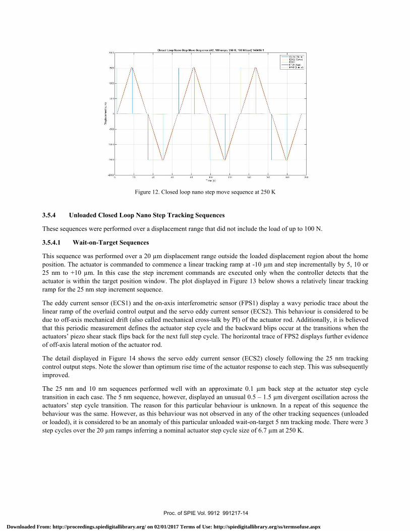
This sequence displayed in Figure 12 is performed in closed loop nano step mode in order to examine the effect of the 250 K operating temperature on the nano step mode. The ramp sequences are the same as used in the open loop sequence above. This stepping mode is critical to the overall performance of the actuator in this application with the BSM. In this case there is no displacement drift over the full sequence because it is operating in closed loop. This sequence was also performed three times to provide a more reliable statistical basis. The actuator performed to well within the required specifications at 250 K for ramp velocity for this closed loop nano step mode with a mean velocity of 100.45 µm/second which meets the requested velocity of 100 µm/second.
Proc. of SPIE Vol. 9912 991217-13
Downloaded From: http://proceedings.spiedigitallibrary.org/ on 02/01/2017 Terms of Use: http://spiedigitallibrary.org/ss/termsofuse.aspx
Closed Loop Nano Step Move Sequence (A2, 100 amps 100 N load) 140116 -1
Times)120
ened OuiputS] (Sava)
P51'í19'9)FPS] (late.)
140 160 180 200
Figure 12. Closed loop nano step move sequence at 250 K
3.5.4 Unloaded Closed Loop Nano Step Tracking Sequences
These sequences were performed over a displacement range that did not include the load of up to 100 N.
3.5.4.1 Wait-on-Target Sequences
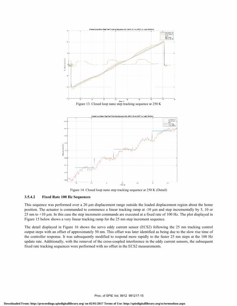
This sequence was performed over a 20 µm displacement range outside the loaded displacement region about the home position. The actuator is commanded to commence a linear tracking ramp at -10 µm and step incrementally by 5, 10 or 25 nm to +10 µm. In this case the step increment commands are executed only when the controller detects that the actuator is within the target position window. The plot displayed in Figure 13 below shows a relatively linear tracking ramp for the 25 nm step increment sequence.
The eddy current sensor (ECS1) and the on-axis interferometric sensor (FPS1) display a wavy periodic trace about the linear ramp of the overlaid control output and the servo eddy current sensor (ECS2). This behaviour is considered to be due to off-axis mechanical drift (also called mechanical cross-talk by PI) of the actuator rod. Additionally, it is believed that this periodic measurement defines the actuator step cycle and the backward blips occur at the transitions when the actuators’ piezo shear stack flips back for the next full step cycle. The horizontal trace of FPS2 displays further evidence of off-axis lateral motion of the actuator rod.
The detail displayed in Figure 14 shows the servo eddy current sensor (ECS2) closely following the 25 nm tracking control output steps. Note the slower than optimum rise time of the actuator response to each step. This was subsequently improved.
The 25 nm and 10 nm sequences performed well with an approximate 0.1 µm back step at the actuator step cycle transition in each case. The 5 nm sequence, however, displayed an unusual 0.5 – 1.5 µm divergent oscillation across the actuators’ step cycle transition. The reason for this particular behaviour is unknown. In a repeat of this sequence the behaviour was the same. However, as this behaviour was not observed in any of the other tracking sequences (unloaded or loaded), it is considered to be an anomaly of this particular unloaded wait-on-target 5 nm tracking mode. There were 3 step cycles over the 20 µm ramps inferring a nominal actuator step cycle size of 6.7 µm at 250 K.
Proc. of SPIE Vol. 9912 991217-14
Downloaded From: http://proceedings.spiedigitallibrary.org/ on 02/01/2017 Terms of Use: http://spiedigitallibrary.org/ss/termsofuse.aspx
Closed Loop Nano Step Feet T
Closed Loop Nano Step Fat
racking Sequence (A2, 250 K, 2!
40Time fai
I Tracking Sequence (A2, 250 K, SI
Tima (a)
s nm, WOT, no load) 140416-2
S nm, WOT, no load) 140416-2
u,s «,s,)1L,te,,,
3.5.4.2 F
This sequencposition. The25 nm to +10Figure 15 bel
The detail dioutput steps the controllerupdate rate. Afixed rate tra
ixed Rate 100
ce was performe actuator is co0 µm. In this calow shows a ve
isplayed in Figwith an offset r response. It wAdditionally, wcking sequence
Figure 13
Figure 14. Cl
0 Hz Sequence
med over a 20 µommanded to case the step incery linear track
gure 16 showsof approximatwas subsequenwith the removes were perform
3. Closed loop n
losed loop nano
es
µm displacemecommence a licrement commking ramp for t
s the servo edtely 50 nm. Thntly modified tval of the crossmed with no o
ano step tracking
step tracking seq
ent range outsiinear tracking r
mands are executhe 25 nm step
dy current senhis offset was lto respond mos-coupled interffset in the EC
g sequence at 25
quence at 250 K
ide the loaded ramp at -10 µmuted at a fixed increment seq
nsor (ECS2) foater identified
ore rapidly to trference in the
CS2 measureme
50 K
K (Detail)
displacement m and step incrate of 100 Hz
quence.
ollowing the 2as being due t
the faster 25 neddy current s
ents.
region about thcrementally by z. The plot disp
25 nm trackingto the slow risenm steps at thesensors, the sub
he home 5, 10 or
played in
g control e time of e 100 Hz bsequent
Proc. of SPIE Vol. 9912 991217-15
Downloaded From: http://proceedings.spiedigitallibrary.org/ on 02/01/2017 Terms of Use: http://spiedigitallibrary.org/ss/termsofuse.aspx

o
o
.°8 2,14
2A2
2 38
888'
Closed Loop Nano Step Fast l
Closed Loop Nano Step Fa,
Tracking Sequence (A2, 250 K 25 me
Tima (a) 8
at Tracking Sequence (A2, 250 K 25
Tima (0
n,100I2,no load) 140416-Y
nm, 10012noloeE)140410-:
The trackingmeasurementsequences, reIt was subseAdditionally,fixed rate tra
Small oscillapeak were obinferring a no
F
g performance t to the controespectively. Thequently modi, with the subscking sequence
ations with a pebserved in the ominal actuato
Figure 15. Cl
Figure 16. Closed
for the 25 nmol output was hese offsets weified at ambiesequent removaes were perform
eriod of approxECS2 Servo) mr step cycle siz
losed loop nano
d loop nano step
m, 10 nm and 5approximately
ere later identifent to respondal of the crossmed with no o
ximately 0.1 –measurements ze of 6.7 µm at
step 100 Hz trac
100 Hz tracking
5 nm sequencey 20 ms, 14 mfied as being d
d more rapidly-coupled interfffset in the EC
0.15 seconds in all sequenc
t 250 K.
cking sequence a
g sequence at 25
es was quite goms and 20 m
due to the slowy to the fasteference in the
CS2 measureme
and an amplitues. There were
at 250 K
50 K (Detail)
ood. The offsems for the 25 nw rise time of th
r steps at theeddy current s
ents.
ude of approxime 3 step cycles
et of the ECS2nm, 10 nm anhe controller r
e 100 Hz updsensors, the sub
mately 10 nm over the 20 µm
2 (servo) nd 5 nm response. date rate. bsequent
peak-to-m ramps
Proc. of SPIE Vol. 9912 991217-16
Downloaded From: http://proceedings.spiedigitallibrary.org/ on 02/01/2017 Terms of Use: http://spiedigitallibrary.org/ss/termsofuse.aspx
Cloaetl Loop Nano Step Fat Tracking Sequence (A2, 250 K, 5 nm, WOT, 100 N load) 150116 -:
Time (a)I
3.5.5 Loaded Closed Loop Nano Step Tracking Sequences
These sequences were performed over a displacement range that did include the load of up to 100 N. However, the performance in the loaded cases was not significantly different to the unloaded sequences described above.
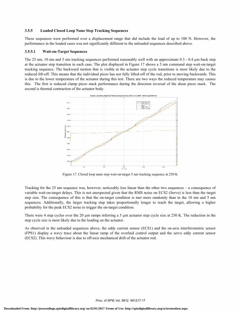
3.5.5.1 Wait-on-Target Sequences
The 25 nm, 10 nm and 5 nm tracking sequences performed reasonably well with an approximate 0.3 - 0.4 µm back step at the actuator step transition in each case. The plot displayed in Figure 17 shows a 5 nm command step wait-on-target tracking sequence. The backward motion that is visible at the actuator step cycle transitions is most likely due to the reduced lift-off. This means that the individual piezo has not fully lifted-off of the rod, prior to moving backwards. This is due to the lower temperature of the actuator during this test. There are two ways the reduced temperature may causes this. The first is reduced clamp piezo stack performance during the direction reversal of the shear piezo stack. The second is thermal contraction of the actuator body.
Figure 17. Closed loop nano step wait-on-target 5 nm tracking sequence at 250 K
Tracking for the 25 nm sequence was, however, noticeably less linear than the other two sequences – a consequence of variable wait-on-target delays. This is not unexpected given that the RMS noise on ECS2 (Servo) is less than the target step size. The consequence of this is that the on-target condition is met more randomly than in the 10 nm and 5 nm sequences. Additionally, the larger tracking step takes proportionally longer to reach the target, allowing a higher probability for the peak ECS2 noise to trigger the on-target condition.
There were 4 step cycles over the 20 µm ramps inferring a 5 µm actuator step cycle size at 250 K. The reduction in the step cycle size is most likely due to the loading on the actuator.
As observed in the unloaded sequences above, the eddy current sensor (ECS1) and the on-axis interferometric sensor (FPS1) display a wavy trace about the linear ramp of the overlaid control output and the servo eddy current sensor (ECS2). This wavy behaviour is due to off-axis mechanical drift of the actuator rod.
Proc. of SPIE Vol. 9912 991217-17
Downloaded From: http://proceedings.spiedigitallibrary.org/ on 02/01/2017 Terms of Use: http://spiedigitallibrary.org/ss/termsofuse.aspx

Closed Loop Nano Step Fat Tracking Sequence (A2, 250 K, 5 nm, 10012, 100 N load) 140/16 -1
Time (s)
3.5.5.2 Fixed Rate 100 Hz Sequences
The plot displayed in Figure 18 shows a 5 nm command step wait-on-target tracking sequence. The tracking ramp is very linear with only a very small offset between the control output and ECS2 servo traces. The backward motion is visible at the actuator step cycle transitions.
The tracking performance for the 25 nm, 10 nm and 5 nm sequences was quite good. The offset of the ECS2 (servo) measurement to the control output was approximately 30 ms, 30 ms and 10 ms, for the 25 nm, 10 nm and 5 nm sequences, respectively. As in the unloaded case, this offset was identified as being due to the slow rise time of the controller response. With the improvements discussed above, this sequence was performed with no offset in the ECS2 measurements.
Small oscillations with a period of approximately 0.1 – 0.15 seconds and an amplitude of approximately 10 nm peak-to-peak were observed in the ECS2 Servo) measurements in all sequences. There were 5 step cycles over the 20 µm ramps inferring an actuator step cycle size of 4 µm at 250 K.
Figure 18. Closed loop nano step 100 Hz 5 nm tracking sequence at 250 K
3.6 Cryogenic Test Outcomes
The results obtained from the test sequences performed under cryogenic conditions were very encouraging and confirmed that the actuators and displacement sensors are capable of providing the level of performance necessary for moving forward with the BSM design. The piezoelectric actuators performed very well, particularly at the fine 5, 10 and 25 nm tracking levels. While there were some observed anomalies in their inter-step cycle behaviour, it is believed that these will not be an issue in a fully optimized BSM installation. Specifically, heating the actuators, with only a small amount of input heat required, enables the use of the OTS piezoelectric actuators with minimal modification. The ANU is working with the manufacturer (PI) to make some small changes to improve lift-off and eliminate the small backward step apparent in the closed loop nano-step load tests. Possible solutions are modified waveforms, increased clamp voltage or modification of the pre-load of the stacks on to the actuator rod. Due to the good performance of the eddy current sensors, they could be considered as the primary servoing sensor when correctly calibrated against the interferometric sensors for installation and temperature-induced non-linearities. Although they are susceptible to
Proc. of SPIE Vol. 9912 991217-18
Downloaded From: http://proceedings.spiedigitallibrary.org/ on 02/01/2017 Terms of Use: http://spiedigitallibrary.org/ss/termsofuse.aspx

electrical noise and interference, with proper wiring and installation practices, this can be reduced to levels significantly below the required sensor resolution.
Post-cryogenic bench testing of the actuator assembly, after addressing the issues of sensor cross talk interference, and improving the controller servo loop performance, has resulted in significant improvements to the performance of the system.
4 DESCRIPTION OF PROPOSED DESIGN
To address some of the issues and deficiencies found through the testing of the prototype BSM assembly and the single actuator, a modified version of the BSM assembly has been designed. The new design also benefits from some design changes to the GMTIFS cryostat. This system uses the same six eddy current sensors arranged in three differential pairs, and the same three interferometric sensors. The elements of each differential sensor pair are placed on opposite sides of the mirror, with the mirror rim extended considerably to accommodate those at the front. In Figure 19 below the three interferometric sensors are placed in front of the mirror, directly opposite the three piezoelectric actuators. In the proposed design these sensors will be located beneath the mirror to reduce the combined lateral and angular motion of the target and avoid the loss of signal seen in the BSM assembly testing. This will also remove the risk of scatter of the FPS laser from the optical surface of the BSM.
Figure 19. A cutaway 3D wire frame and plan view of the prototype beam steering system show the layout of the three point actuator
support and position encoding.
5 CONCLUSIONS
The GMTIFS beam steering mirror concept provides an elegant design solution capable of meeting the stringent positioning accuracies demanded by adaptive optics observations on the Giant Magellan Telescope. Allowing access to the full available guide field from which to draw guide stars will ensure GMT/GMTIFS provides high sky coverage for observations of key science targets. Precision control of the beam steering system will ensure high precision relative offsetting can be performed allowing accurate image registration in post processing. The prototype testing of the actuator, sensors and the BSM assembly has delivered results that provide confidence in the chosen design strategy.
Proc. of SPIE Vol. 9912 991217-19
Downloaded From: http://proceedings.spiedigitallibrary.org/ on 02/01/2017 Terms of Use: http://spiedigitallibrary.org/ss/termsofuse.aspx

Australian membership in the GMT consortium is funded by the Department of Innovation, Industry, Science and Research, and Tertiary Education (DIISRTE) through the Australian Government Education Investment Fund (EIF). The GMTIFS Conceptual Design Study was funded by EIF, the Giant Magellan Telescope Organization (GMTO), and the National Science Foundation under Science Program No. 10 as issued for support of the Giant Segmented Mirror Telescope for the United States Astronomical Community in accordance with Proposal No. AST-0443999 submitted by AURA.
REFERENCES
[1] McGregor, P. J., Hart, J., Conroy, P. G., Pfitzner, M. L., Bloxham, G. J., Jones, D. J., Downing, M. D., Dawson, M., Young, P., Jarnyk, M., and Van Harmelen, J., “Gemini near-infrared integral field spectrograph (NIFS),” in [Instrument Design and Performance for Optical/Infrared Ground-based Telescopes ], Iye, M. and Moorwood, A. F. M., eds., Society of Photo-Optical Instrumentation Engineers (SPIE) Conference Series 4841, 1581–1591 (Mar. 2003).
[2] Hart, J., McGregor, P. J., and Bloxham, G. J., “NIFS concentric integral field unit,” in [Instrument Design and Performance for Optical/Infrared Ground-based Telescopes ], Iye, M. and Moorwood, A. F. M., eds., Society of Photo-Optical Instrumentation Engineers (SPIE) Conference Series 4841, 319–329 (Mar. 2003).
[3] McGregor, P., Hart, J., Stevanovic, D., Bloxham, G., Jones, D., Van Harmelen, J., Griesbach, J., Dawson, M., Young, P., and Jarnyk, M. A., “Gemini South Adaptive Optics Imager (GSAOI),” in [Ground-based Instrumentation for Astronomy ], Moorwood, A. F. M. and Iye, M., eds., Society of Photo-Optical Instrumentation Engineers (SPIE) Conference Series 5492, 1033–1044 (Sept. 2004).
[4] Carrasco, E. R., Edwards, M. L., McGregor, P. J., Winge, C., Young, P. J., Doolan, M. C., van Harmelen, J., Rigaut, F. J., Neichel, B., Trancho, G., Artigau, E., Pessev, P., Colazo, F., Tigner, J., Mauro, F., Lu¨hrs, J., and Rambold, W. N., “Results from the commissioning of the Gemini South Adaptive Optics Imager (GSAOI) at Gemini South Observatory,” in [Society of Photo-Optical Instrumentation Engineers (SPIE) Conference Series], Society of Photo-Optical Instrumentation Engineers (SPIE) Conference Series 8447 (July 2012).
[5] Esposito, S., Pinna, E., Quiro´s-Pacheco, F., Puglisi, A. T., Carbonaro, L., Bonaglia, M., Biliotti, V., Briguglio, R., Agapito, G., Arcidiacono, C., Busoni, L., Xompero, M., Riccardi, A., Fini, L., and Bouchez, A., “Wavefront sensor design for the GMT natural guide star AO system,” in [Society of Photo-Optical Instrumentation Engineers (SPIE) Conference Series], Society of Photo-Optical Instrumentation Engineers (SPIE) Conference Series 8447 (July 2012).
[6] Wang, M., Uhlendorf, K., Jones, D., Cˆot´e, P., Chˆateauneuf, F., Gauvin, J., Conan, R., and Espeland, B., “Optical designs of the LGS WFS system for GMT-LTAO,” in [Society of Photo-Optical Instrumentation Engineers (SPIE) Conference Series], Society of Photo-Optical Instrumentation Engineers (SPIE) Conference Series 8447 (July 2012).
[7] Sharp R., Boz R., Hart J., Bloxham, G., Bundy, D., Davies, J., McGregor, P.J., Nielsen, J., Vest, C., Young, P.J., “The adaptive optics beam steering mirror for the GMT Integral-Field Spectrograph, GMTIFS”, in [Advances in Optical and Me4chanical Technologies for Telescopes and Instrumentation], Society of Photo-Optical Instrumentation Engineers (SPIE) Conference Series 9151 (June 2014).
ACKNOWLEDGMENTS
Proc. of SPIE Vol. 9912 991217-20
Downloaded From: http://proceedings.spiedigitallibrary.org/ on 02/01/2017 Terms of Use: http://spiedigitallibrary.org/ss/termsofuse.aspx