go ren,olrilo eiteatr,ok,oye uiciroyesoeikc,odbj paralleling technique the paralleling technique is...
TRANSCRIPT
Go Green, Go Online to take your course
Earn
3 CE creditsThis course was
written for dentists, dental hygienists,
and assistants.
This course has been made possible through an unrestricted educational grant. The cost of this CE course is $49.00 for 3 CE credits. Cancellation/Refund Policy: Any participant who is not 100% satisfied with this course can request a full refund by contacting PennWell in writing.
Best Practices in Intraoral Digital RadiographyA Peer-Reviewed Publication Written by Gail F. Williamson, RDH, MS
Published: August 2010Expiry: July 2013

2 www.ineedce.com
Educational ObjectivesThe overall goal of this article is to provide the reader with information on intraoral digital radiography. Upon completion of this course, the reader will be able to: 1. List and describe the types of digital receptors used
for intraoral radiographic imaging.2. List and describe the principles of paralleling and
bisecting angle techniques for effective and accurate intraoral digital radiography.
3. List and describe the adjustments in technique that may be necessary to accommodate anatomy, discomfort and placement difficulties.
4. List and describe best practices for patient radiation safety and protection.
5. List and describe common errors that occur when taking intraoral digital radiographs and corrections that can be made when errors occur.
AbstractDetailed, accurate radiographs are a primary diagnostic tool as well as necessary for and during some treatments. Increasingly, digital radiographic imaging is being used with two types of available receptors. Anatomical varia-tions and patient comfort must be considered when taking intraoral radiographs. In addition, recognizing common sources of errors is important to ensure that the clinician avoids them and knows how to correct them when they occur. Techniques, as well as devices and accessories, can be used that will enable accurate image acquisition and improve patient comfort.
IntroductionDental radiographs are taken as primary diagnostic tools and for treatment purposes. As such, they must be as detailed and accurate as possible to meet clinical require-ments. Increasingly, digital radiography is becoming the technology of choice and offers several advantages over film radiography. These include the ability to view im-ages on the screen, computerized archiving of images, ability to enhance acquired images, reduced exposure to radiation, and rapid acquisition of images without the need for chemical processing. In order to produce high-quality diagnostic images, a careful technique is required that considers best practices and patient comfort. Accurate technique, effective patient manage-ment, and proper exposure are required to optimize the information that can be obtained from radiographs and, therefore, their value.
Typically, radiographic examinations are used to evaluate oral disease states such as periodontal disease, caries, and periapical pathology. While for periodontal disease and periapical pathology the radiographic projec-tion of choice is usually a periapical or series of periapical images that record the entire tooth and supporting bone
and is of value in diagnosing bony and root pathoses, bitewing radiographs are the radiograph of choice for the detection and monitoring of dental caries in the posterior teeth and can also better detect alveolar bone levels in these sextants. Vertical bitewings (size 1) may also be used to take images of the anterior teeth to assess alveo-lar bone levels. The patient’s medical and dental history, clinical signs and symptoms of disease, risk factors, age and dentition, and new or recall patient status must also be considered when determining which radiographs are required. Recommendations are available for the ap-propriate patient-specific selection of radiographs (The Selection of Patients for Dental Radiographic Examina-tions, Revised 2004).1 The overall objective of intraoral radiography is to minimize exposure to radiation while maximizing the diagnostic and interpretative value of the radiographs. The focus of this article is on the use of digital radiography, which in the last two decades has steadily increased.
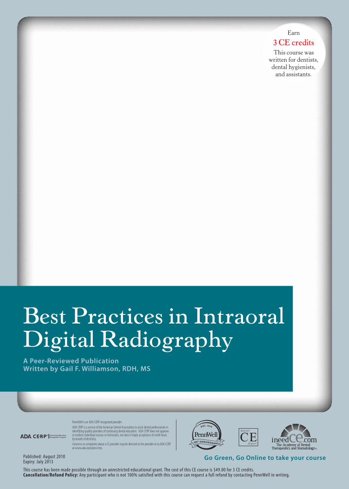
I. Digital ReceptorsDigital receptors are available in two formats: 1) pho-tostimulable phosphor plate (PSP) receptors; or 2) rigid wired or wireless charge-coupled devices (CCD), complementary metal oxide semi-conductors (CMOS) or complementary-metal-oxide semiconductor active pixel sensor (CMOS-APS) receptors. These rigid digital receptors are often referred to as sensors and the term is used interchangeably. Both systems are computer-based technologies that require specific hardware and software components for operation.
Digital receptors are faster than film, which reduces the amount of radiation needed to produce a diagnostic image and eliminate chemical processing errors, darkroom main-tenance, and chemical waste disposal. They are available in sizes comparable to film, most typically sizes 0, 1, and 2. Both types of digital receptors are reusable. Therefore, it is important for the clinician to consult the manufacturer’s in-structions for proper preparation and coverage of the recep-tor, as well as for effective barrier removal techniques. Care must be taken to avoid direct saliva contact with the recep-tor and prevent cross-contamination. Disinfection can be accomplished with ADA- or EPA-approved products and typical disinfection techniques followed by coverage with an effective barrier. For rigid receptors, the Centers for Dis-ease Control and Prevention recommends using a double barrier, with both an internal and external barrier.2
Phosphor plate receptors are more flexible and thin-ner than rigid digital receptors but have the same dimen-sions as film. Plate receptors are used much like film but must be handled carefully, scanned to digitize the image, and erased before reuse. Rough handling may produce plate scars, result in image artifacts, and necessitate plate replacement, making them less user friendly in these in-
www.ineedce.com 3
stances.3 These problems in turn may result in retakes, thereby increasing patients’ radiation exposure. Recent improvements in plate technology have been directed toward making plates more scratch resistant to improve longevity, and permitting immediate erasure after scan-ning to save time.
Figure 1. Digital receptors
Phosphor plate receptors
Rigid digital receptors
Rigid digital receptors are more difficult to use initially than phosphor plate receptors, and may result in more problems for both periapical and bitewing radiographic images when compared to film. Common issues associ-ated with rigid digital receptors include: 1. placement errors, especially in premolar and molar areas; 2. verti-cal angulation errors in the anterior regions, resulting in incisal edge cutoffs; 3. horizontal overlapping; 4. cone-cutting; 5. difficulties with bitewing placement, especially premolar views and vertical bitewings; and 6. discomfort.4-7 To avoid these problems, attention to the details of placement in terms of precise location, horizontal and vertical parallelism of the receptor to the structures, and accurate alignment of the x-ray beam are critical. To avoid cutting off incisal edges, a cotton roll can be placed on the biteblock to facilitate placement and allow the crowns to be fully recorded. In addition, rigid receptors should be placed closer to the midline to reduce discomfort and to achieve a parallel rather than angular placement. It is particularly important to employ this approach when a patient has a shallow palate or floor of mouth, both to avoid discomfort and distortion of the
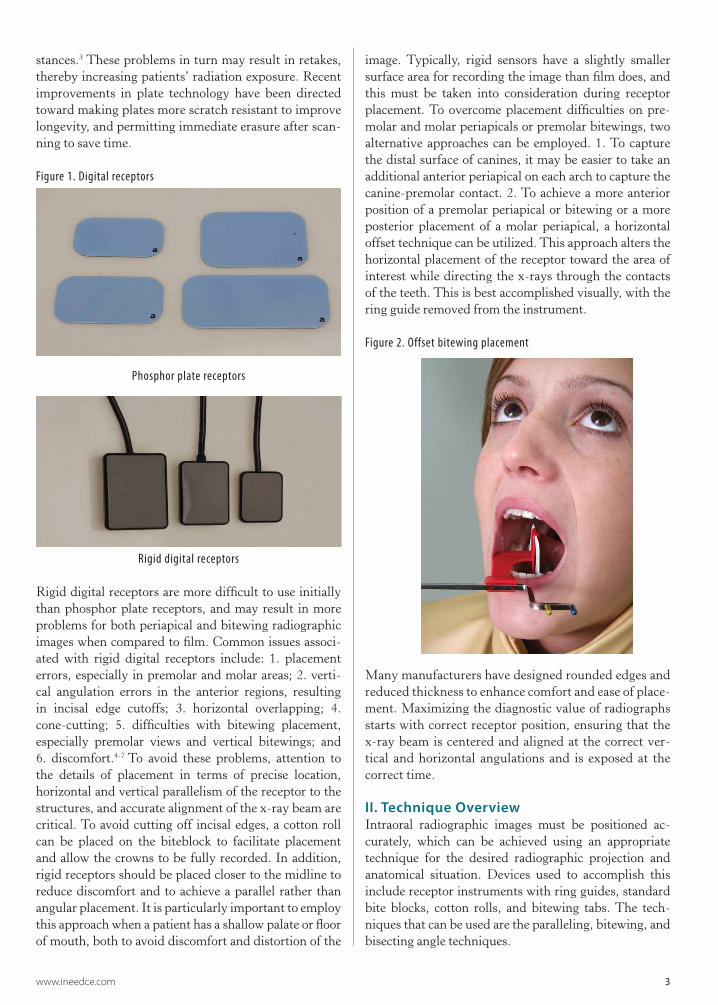
image. Typically, rigid sensors have a slightly smaller surface area for recording the image than film does, and this must be taken into consideration during receptor placement. To overcome placement difficulties on pre-molar and molar periapicals or premolar bitewings, two alternative approaches can be employed. 1. To capture the distal surface of canines, it may be easier to take an additional anterior periapical on each arch to capture the canine-premolar contact. 2. To achieve a more anterior position of a premolar periapical or bitewing or a more posterior placement of a molar periapical, a horizontal offset technique can be utilized. This approach alters the horizontal placement of the receptor toward the area of interest while directing the x-rays through the contacts of the teeth. This is best accomplished visually, with the ring guide removed from the instrument.
Figure 2. Offset bitewing placement
Many manufacturers have designed rounded edges and reduced thickness to enhance comfort and ease of place-ment. Maximizing the diagnostic value of radiographs starts with correct receptor position, ensuring that the x-ray beam is centered and aligned at the correct ver-tical and horizontal angulations and is exposed at the correct time.
II. Technique OverviewIntraoral radiographic images must be positioned ac-curately, which can be achieved using an appropriate technique for the desired radiographic projection and anatomical situation. Devices used to accomplish this include receptor instruments with ring guides, standard bite blocks, cotton rolls, and bitewing tabs. The tech-niques that can be used are the paralleling, bitewing, and bisecting angle techniques.
4 www.ineedce.com
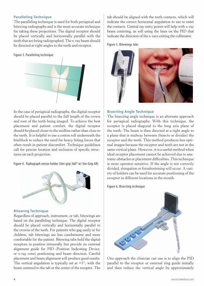
Paralleling TechniqueThe paralleling technique is used for both periapical and bitewing radiographs and is the most accurate technique for taking these projections. The digital receptor should be placed vertically and horizontally parallel with the teeth that are being radiographed. The x-ray beam should be directed at right angles to the teeth and receptor.
Figure 3. Paralleling technique
In the case of periapical radiographs, the digital receptor should be placed parallel to the full length of the crown and root of the teeth being imaged. To achieve the best placement and patient comfort, the digital receptor should be placed closer to the midline rather than close to the teeth. It is helpful to use a cotton roll underneath the biteblock to reduce the need for heavy biting forces that often result in patient discomfort. Technique guidelines call for precise location and inclusion of specific struc-tures on each projection.
Figure 4. Radiograph sensor holder (Uni-grip 360® w/ Uni-Grip AR)
Bitewing TechniqueRegardless of approach, instrument, or tab, bitewings are based on the paralleling technique. The digital receptor should be placed vertically and horizontally parallel to the crowns of the teeth. For patients who gag easily or for children, tab bitewings are less cumbersome and more comfortable for the patient. Bitewing tabs hold the digital receptors in position intraorally but provide no external alignment guide for PID (Position Indicating Device, or x-ray cone) positioning and beam direction. Careful placement and beam alignment will produce good results. The vertical angulation is typically set at +5°, with the beam centered to the tab or the center of the receptor. The
tab should be aligned with the teeth contacts, which will indicate the correct horizontal angulation to use to enter the contacts. Central ray entry points will help with x-ray beam centering, as will using the lines on the PID that indicate the direction of the x-rays exiting the collimator.
Figure 5. Bitewings tabs
Bisecting Angle TechniqueThe bisecting angle technique is an alternate approach for periapical radiography. With this technique, the receptor is placed diagonal to the long axis plane of the teeth. The beam is then directed at a right angle to a plane that is midway between (bisects or divides) the receptor and the teeth. This method produces less opti-mal images because the receptor and teeth are not in the same vertical plane. However, it is a useful method when ideal receptor placement cannot be achieved due to ana-tomic obstacles or placement difficulties. This technique is more operator-sensitive. If the angle is not correctly divided, elongation or foreshortening will occur. A vari-ety of holders can be used for accurate positioning of the receptor in different locations in the mouth.
Figure 6. Bisecting technique
One approach the clinician can use is to align the PID parallel to the receptor or external ring guide initially and then reduce the vertical angle by approximately
www.ineedce.com 5
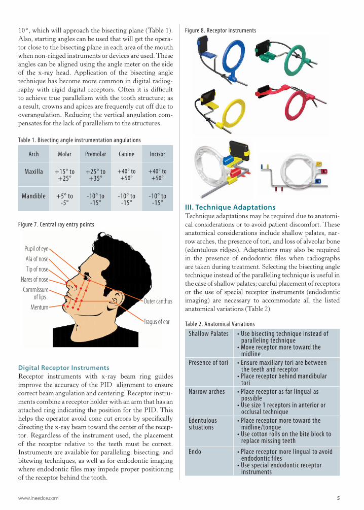
10°, which will approach the bisecting plane (Table 1). Also, starting angles can be used that will get the opera-tor close to the bisecting plane in each area of the mouth when non-ringed instruments or devices are used. These angles can be aligned using the angle meter on the side of the x-ray head. Application of the bisecting angle technique has become more common in digital radiog-raphy with rigid digital receptors. Often it is difficult to achieve true parallelism with the tooth structure; as a result, crowns and apices are frequently cut off due to overangulation. Reducing the vertical angulation com-pensates for the lack of parallelism to the structures.
Table 1. Bisecting angle instrumentation angulations
Arch Molar Premolar Canine Incisor
Maxilla +15° to +25°
+25° to +35°
+40° to +50°
+40° to +50°
Mandible +5° to -5°
-10° to -15°
-10° to -15°
-10° to -15°
Figure 7. Central ray entry points
Pupil of eyeAla of noseTip of nose
Nares of noseCommissure
of lips Mentum
Outer canthus
Tragus of ear
Digital Receptor InstrumentsReceptor instruments with x-ray beam ring guides improve the accuracy of the PID alignment to ensure correct beam angulation and centering. Receptor instru-ments combine a receptor holder with an arm that has an attached ring indicating the position for the PID. This helps the operator avoid cone cut errors by specifically directing the x-ray beam toward the center of the recep-tor. Regardless of the instrument used, the placement of the receptor relative to the teeth must be correct. Instruments are available for paralleling, bisecting, and bitewing techniques, as well as for endodontic imaging where endodontic files may impede proper positioning of the receptor behind the tooth.
Figure 8. Receptor instruments
III. Technique AdaptationsTechnique adaptations may be required due to anatomi-cal considerations or to avoid patient discomfort. These anatomical considerations include shallow palates, nar-row arches, the presence of tori, and loss of alveolar bone (edentulous ridges). Adaptations may also be required in the presence of endodontic files when radiographs are taken during treatment. Selecting the bisecting angle technique instead of the paralleling technique is useful in the case of shallow palates; careful placement of receptors or the use of special receptor instruments (endodontic imaging) are necessary to accommodate all the listed anatomical variations (Table 2).
Table 2. Anatomical VariationsShallow Palates • Use bisecting technique instead of
paralleling technique• Move receptor more toward the midline
Presence of tori • Ensure maxillary tori are between the teeth and receptor• Place receptor behind mandibular tori
Narrow arches • Place receptor as far lingual as possible• Use size 1 receptors in anterior or occlusal technique
Edentulous situations
• Place receptor more toward the midline/tongue• Use cotton rolls on the bite block to replace missing teeth
Endo • Place receptor more lingual to avoid endodontic files• Use special endodontic receptor instruments
6 www.ineedce.com
Projection Or View Receptor Placement Teeth
Recorded Central Ray Entry Point Receptor Orientation
Receptor Size Image
MAXILLARY PERIAPICALS
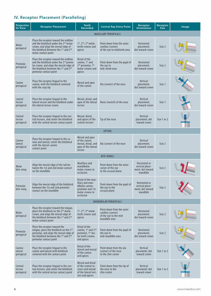
Molar periapical
Place the receptor toward the midline and the biteblock under the 2nd molar crown, and align the mesial edge of the biteblock between the 1st and 2nd molar contact point
1st, 2nd, 3rd molar teeth crowns and apices
Point down from the outer canthus (corner) of the eye to midcheek area
Horizontal placement;
dot toward crownSize 2
Premolar periapical
Place the receptor toward the midline and the biteblock under the 2nd premo-lar crown, and align the mesial edge of the biteblock between the 1st and 2nd premolar contact point
Distal of the canine, 1st and 2nd premolar, 1st molar crowns and apices
Point down from the pupil of the eye to mid-cheek area
Horizontal placement;
dot toward crownSize 2
Canine periapical
Place the receptor lingual to the canine, with the biteblock centered with the cusp tip
Mesial and apex of the canine Ala (corner) of the nose
Vertical placement;
dot toward crownSize 1
Lateral incisor periapical
Place the receptor lingual to the lateral incisor and the biteblock under the lateral incisor crown
Mesial, distal, and apex of the lateral incisor
Nares (nostril) of the noseVertical
placement; dot toward crown
Size 1
Central incisor periapical
Place the receptor lingual to the cen-tral incisors, and center the biteblock with the central incisor contact point
Mesial, distal, and apices of the central incisors
Tip of the noseVertical
placement; dot toward crown
Size 1 or 2
OPTION
Canine- lateral periapical
Place the receptor lingual to the ca-nine and lateral; center the biteblock with the lateral-canine contact point
Mesial and apex of the canine, mesial, distal, and apex of the lateral incisor
Ala (corner) of the noseVertical
placement; dot toward crown
Size 2
BITE-WINGS
Molar bite-wing
Align the mesial edge of the tab be-tween the 1st and 2nd molar contact on the mandible
Maxillary and mandibular molar crowns in occlusion
Point down from the outer corner of the eye to the occusal plane
Horizontal or vertical place-
ment; dot toward mandible
Size 2
Premolar bite-wing
Align the mesial edge of the biteblock between the 1st and 2nd premolar contact on the mandible
Distal of the max-illary and man-dibular canine, premolar and 1st molar crowns in occlusion
Point down from the pupil of the eye to the occusal plane
Horizontal or vertical place-
ment; dot toward mandible
Size 2
MANDIBULAR PERIAPICALS
Molar periapical
Place the receptor toward the tongue, place the biteblock on the 2nd molar crown, and align the mesial edge of the biteblock between the 1st and 2nd molar contact point
1st, 2nd, 3rd molar teeth crowns and apices
Point down from the outer canthus (corner) of the eye to the mid-mandible area
Horizontal placement;
dot toward crownSize 2
Premolar periapical
Place the receptor toward the tongue, place the biteblock on the 2nd premolar, and align the mesial edge of the biteblock between the 1st and 2nd premolar contact point
Distal of the canine, 1st and 2nd premolar, 1st mo-lar teeth crowns and apices
Point down from the pupil of the eye to mid-mandible area
Horizontal placement;
dot toward crownSize 2
Canine- lateral periapical
Place the receptor lingual to the canine and lateral with biteblock centered with the contact point
Distal of the lateral and mesial of the canine and apices
Point down from the ala (corner) of the nose to the chin corner
Vertical placement; dot toward crown
Size 1 or 2
Central incisor periapical
Place the receptor lingual to the cen-tral incisors, and center the biteblock with the central incisor contact point
Mesial and distal of the central in-cisors and mesial of the lateral inci-sors and apices
Point down from the tip of the nose to the chin center
Vertical placement; dot toward crown
Size 1 or 2
IV. Receptor Placement (Paralleling)
www.ineedce.com 7
V. Patient ComfortEnsuring that patients are as comfortable as possible while taking radiographs not only helps patients but also results in a greater likelihood of successful imag-ing and reduced risk of retakes associated with patients moving or altering the position of a digital receptor while the radiograph is being taken. Gagging and dis-comfort associated with the edges of receptors are key considerations.
Gagging patients can be challenging and require patience and reassurance from the clinician. It is impor-tant to be organized, preset the exposure time, pre-align the PID, and be ready to act quickly. The most common area to elicit the gag reflex is the maxillary molar periapi-cal view. Placement of the receptor toward the midline and away from the soft palate will reduce the tendency for gagging. A variety of strategies will help manage the gagging patient: breathing through the nose, salt on the tongue, distraction techniques (lifting one leg in the air, bending the toes toward the body, humming), use of topical anesthetics, and tissue cushions on the receptor.
Similar approaches can be useful when the patient experiences discomfort from the receptor. The use of topical anesthetic agents and receptor cushions improve comfort. Rigid digital receptors can cause more dis-comfort than other receptors; placing these closer to the midline can reduce patient discomfort. This is especially important in patients with a shallow palate or shallow floor of the mouth, because the edge of the receptor is more likely to dig in as there is less space for position-ing and placement of the receptor, and tori necessitate placing the receptor behind them. Using lightweight bite blocks and receptor arms/rings also improves pa-tient comfort. Another option is to use a receptor holder without the accompanying arm and ring, allowing for positioning of the sensor that optimizes patient comfort without compromising accuracy; this requires knowl-edge of the bisecting angle technique and is useful when positioning must accommodate anatomical variations as described above.
In bitewing radiography, tabs can be used and are usually less uncomfortable for the patient, although the edges of a rigid receptor may still be a potential source of discomfort. While regular bitewing tabs are more com-fortable, they are less reliable than the use of a holding device because they may allow movement or displace-ment of the sensor. Bitewing tabs with extended straps that wrap around the sensor solve this problem and keep the tab positioned exactly in the center of the sen-sor and the barrier cover without compromising patient comfort. Self-adhesive foam covers can be used over the receptor for both bitewings and periapicals to smooth the edges and provide cushioning against the patient’s oral mucosa.
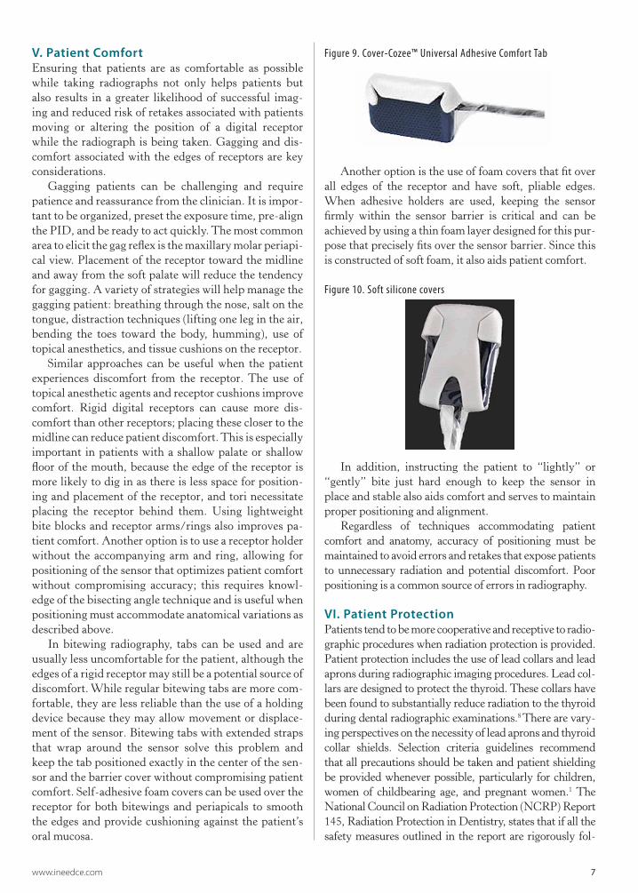
Figure 9. Cover-Cozee™ Universal Adhesive Comfort Tab
Another option is the use of foam covers that fit over all edges of the receptor and have soft, pliable edges. When adhesive holders are used, keeping the sensor firmly within the sensor barrier is critical and can be achieved by using a thin foam layer designed for this pur-pose that precisely fits over the sensor barrier. Since this is constructed of soft foam, it also aids patient comfort.
Figure 10. Soft silicone covers
In addition, instructing the patient to “lightly” or “gently” bite just hard enough to keep the sensor in place and stable also aids comfort and serves to maintain proper positioning and alignment.
Regardless of techniques accommodating patient comfort and anatomy, accuracy of positioning must be maintained to avoid errors and retakes that expose patients to unnecessary radiation and potential discomfort. Poor positioning is a common source of errors in radiography.
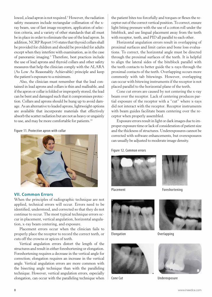
VI. Patient ProtectionPatients tend to be more cooperative and receptive to radio-graphic procedures when radiation protection is provided. Patient protection includes the use of lead collars and lead aprons during radiographic imaging procedures. Lead col-lars are designed to protect the thyroid. These collars have been found to substantially reduce radiation to the thyroid during dental radiographic examinations.8 There are vary-ing perspectives on the necessity of lead aprons and thyroid collar shields. Selection criteria guidelines recommend that all precautions should be taken and patient shielding be provided whenever possible, particularly for children, women of childbearing age, and pregnant women.1 The National Council on Radiation Protection (NCRP) Report 145, Radiation Protection in Dentistry, states that if all the safety measures outlined in the report are rigorously fol-
8 www.ineedce.com
lowed, a lead apron is not required.9 However, the radiation safety measures include rectangular collimation of the x-ray beam, use of fast image receptors, application of selec-tion criteria, and a variety of other standards that all must be in place in order to eliminate the use of the lead apron. In addition, NCRP Report 145 states that thyroid collars shall be provided for children and should be provided for adults except when they interfere with examination, as in the case of panoramic imaging.9 Therefore, best practices include the use of lead aprons and thyroid collars and other safety measures that help the clinician comply with the ALARA (As Low As Reasonably Achievable) principle and keep the patient’s exposure to a minimum.
Also, the clinician must remember that the lead con-tained in lead aprons and collars is thin and malleable, and if the apron or collar is folded or improperly stored, the lead can be bent and damaged such that it compromises protec-tion. Collars and aprons should be hung up to avoid dam-age. As an alternative to leaded aprons, lightweight options are available that incorporate materials that effectively absorb the scatter radiation but are not as heavy or ungainly to use, and may be more comfortable for patients.10
Figure 11. Protective apron with collar
VII. Common ErrorsWhen the principles of radiographic technique are not applied, technical errors will occur. Errors need to be identified, understood, and corrected so that they do not continue to occur. The most typical technique errors oc-cur in placement, vertical angulation, horizontal angula-tion, x-ray beam centering, and exposure.
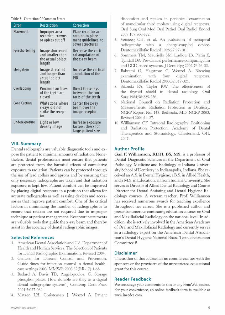
Placement errors occur when the clinician fails to properly place the receptor to record the correct teeth, or cuts off the crowns or apices of teeth.
Vertical angulation errors distort the length of the structures and result in either foreshortening or elongation. Foreshortening requires a decrease in the vertical angle for correction; elongation requires an increase in the vertical angle. Vertical angulation errors are more common with the bisecting angle technique than with the paralleling technique. However, vertical angulation errors, especially elongation, can occur with the paralleling technique when
the patient bites too forcefully and torques or flexes the re-ceptor out of the correct vertical position. To correct, ensure light biting pressure with the use of a cotton roll under the biteblock, and use lingual placement away from the teeth with receptor, teeth, and PID all parallel to each other.
Horizontal angulation errors result in overlapping of proximal surfaces and limit caries and bone loss evalua-tions. To correct, the horizontal angle must be directed through the proximal surfaces of the teeth. It is helpful to align the lateral sides of the biteblock parallel with the teeth contacts to better guide the x-rays through the proximal contacts of the teeth. Overlapping occurs more commonly with tab bitewings. However, overlapping can occur with bitewing instruments if the receptor is not placed parallel to the horizontal plane of the teeth.
Cone cut errors are caused by not centering the x-ray beam over the receptor. Lack of centering produces par-tial exposure of the receptor with a “cut” where x-rays did not interact with the receptor. Receptor instruments with beam guides facilitate beam centering over the re-ceptor when properly assembled.
Exposure errors result in light or dark images due to im-proper exposure time or lack of consideration of patient size and the thickness of structures. Underexposures cannot be corrected with software enhancements, but overexposures can usually be adjusted to moderate image density.
Figure 12. Common errors
Placement Foreshortening
Elongation Overlapping
Cone Cut Underexposure
www.ineedce.com 9
Table 3: Correction Of Common Errors
Error Description CorrectionPlacement Improper area
recorded, crowns or apices cut off
Place receptor ac-cording to place-ment guidelines to cover structures
Foreshortening Image shortened and smaller than the actual object length
Decrease the verti-cal angulation of the x-ray beam
Elongation Image stretched and longer than actual object length
Increase the vertical angulation of the PID
Overlapping Proximal surfaces of the teeth are closed
Direct the x-rays between the con-tacts of the teeth
Cone Cutting White zone where x-rays did not strike the recep-tor
Center the x-ray beam over the image receptor
Underexposure Light or low density image
Increase exposure factors; check for large patient size
VIII. SummaryDental radiographs are valuable diagnostic tools and ex-pose the patient to minimal amounts of radiation. None-theless, dental professionals must ensure that patients are protected from the harmful effects of cumulative exposure to radiation. Patients can be protected through the use of lead collars and aprons and by ensuring that only necessary radiographs are taken and that radiation exposure is kept low. Patient comfort can be improved by placing digital receptors in a position that allows for accurate radiographs as well as using devices and acces-sories that improve patient comfort. One of the critical factors in minimizing the number of radiographs is to ensure that retakes are not required due to improper technique or patient management. Receptor instruments are valuable tools that guide the x-ray beam and thereby assist in the accuracy of dental radiographic images.
Selected References1. AmericanDentalAssociationandU.S.Departmentof
HealthandHumanServices.TheSelectionofPatientsforDentalRadiographicExamination,Revised2004.
2. Centers for Disease Control and Prevention.Guide¬lines for infection control in dental health-caresettings2003.MMWR2003;52(RR-17):1-68.
3. Bedard A, Davis TD, Angelopoulos, C. Storagephosphor plates: How durable are they as a digitaldental radiographic system? J Contemp Dent Pract2004;5:057-069.
4. Matzen LH, Christensen J, Wenzel A. Patient
discomfort and retakes in periapical examinationof mandibular third molars using digital receptors.OralSurgOralMedOralPatholOralRadiolEndod2009;107:566-572.
5. Versteeg CH, et al. An evaluation of periapicalradiography with a charge-coupled device.DentomaxillofacRadiol1998;27:97-101.
6. SommersTM, Mauriello SM, Ludlow JB, Platin E,TyndallDA.Pre-clinicalperformancecomparingfilmandCCD-basedsystems.JDentHyg2002;76:26-33.
7. Bahrami G, Hagstrom C, Wenzel A. Bitewingexamination with four digital receptors.DentomaxillofacRadiol2003;32:317-321.
8. Sikorski PA, Taylor KW. The effectiveness ofthe thyroid shield in dental radiology. OralSurg.1984;58:225-236.
9. National Council on Radiation Protection andMeasurements. Radiation Protection in Dentistry.NCRPReportNo.145.Bethesda,MD.NCRP2003,Revised2004;14-27.
10.Williamson GF. Intraoral Radiography: Positioningand Radiation Protection. Academy of DentalTherapeutics and Stomatology, Chesterland, OH,2007.
Author ProfileGail F. Williamson, RDH, BS, MS, is a professor of Dental Diagnostic Sciences in the Department of Oral Pathology, Medicine and Radiology at Indiana Univer-sity School of Dentistry in Indianapolis, Indiana. She re-ceived an A.S. in Dental Hygiene, a B.S. in Allied Health, and a M.S. in Education, all from Indiana University. She serves as Director of Allied Dental Radiology and Course Director for Dental Assisting and Dental Hygiene Ra-diology courses. A veteran teacher, Prof. Williamson has received numerous awards for teaching excellence throughout her career. She is a published author and presents numerous continuing education courses on Oral and Maxillofacial Radiology on the national level. In ad-dition, she is actively involved in the American Academy of Oral and Maxillofacial Radiology and currently serves as a radiology expert on the American Dental Associa-tion’s Dental Hygiene National Board Test Construction Committee B.
DisclaimerThe author of this course has no commercial ties with the sponsors or the providers of the unrestricted educational grant for this course.
Reader FeedbackWe encourage your comments on this or any PennWell course. For your convenience, an online feedback form is available at www.ineedce.com.

10 www.ineedce.com
Questions
Online CompletionUse this page to review the questions and answers. Return towww.ineedce.comand sign in. If you have not previously purchased the program select it from the “Online Courses” listing and complete the online purchase. Once purchased the exam will be added to your Archives page where a Take Exam link will be provided. Click on the “Take Exam” link, complete all the program questions and submit your answers. An immediate grade report will be provided and upon receiving a passing grade your “Verification Form” will be provided immediately for viewing and/or printing. Verification Forms can be viewed and/or printed anytime in the future by returning to the site, sign in and return to your Archives Page.
1. Dental radiographs are taken ________a. for treatment purposesb. as primary diagnostic toolsc. as definitive tools d. a and b
2. _________ is an advantage of digital radiography over film radiography. a. Computerized archiving of imagesb. The ability to enhance acquired imagesc. Rapid acquisition of images without the need for
chemical processing d. all of the above
3. For periapical pathology, the radio-graphic projection of choice is usually _________.a. a series of bitewing imagesb. a series of periapical imagesc. a series of periapical and bitewing imagesd. none of the above
4. Digital receptors are available in ________.a. rigid wired or wireless charge-coupled devicesb. photostimulable phosphor plate (PSP) receptors c. complementary metal oxide semi-conductors
or complementary-metal-oxide semiconductor active pixel sensor receptors
d. all of the above5. For rigid receptors, the Centers for
Disease Control and Prevention recommends _________.a. using a single barrier, with an external barrierb. using a single barrier, with an internal barrierc. using a double barrier, with both an internal and
external barrierd. using a single barrier, with both an internal and
external barrier6. Phosphor plate receptors _________.
a. are more flexible than rigid receptorsb. are thinner than rigid receptorsc. have the same dimensions as filmd. all of the above
7. To capture the distal surface of canines, it may be easier to take an additional anterior periapicals on each arch to capture the _________.a. canine-lateral incisor contactb. premolar-premolar contactc. canine-premolar contactd. all of the above
8. The paralleling technique is used for _________ radiographs.a. periapicalb. bitewingc. panoramicd. a and b
9. For the paralleling technique, the x-ray beam should be directed _________ to the teeth and receptor.a. perpendicularb. at an acute anglec. at right anglesd. at an obtuse angle
10. For patients who gag easily or for children, tab bitewings are _________ for the patient.a. less convenientb. less cumbersomec. more comfortabled. b and c
11. Central ray entry points will help with _________.a. positioning of the sensor plateb. x-ray beam reductionc. x-ray beam lateralizationd. x-ray beam centering
12. The bisecting angle technique is an alternate approach for _________.a. bitewing radiographyb. periapical radiographyc. occlusal radiography d. all of the above
13. Application of the bisecting angle technique has become more common in digital radiography with _________.a. rigid digital receptorsb. flexible digital receptorsc. flexible x-ray filmd. none of the above
14. When using the bisecting angle technique, for a maxillary molar the angulation should be _________.a. +15° to +25°b. -15° to - 25°c. +25° to +35°d. -25° to -35°
15. When using the bisecting angle technique, for a mandibular canine the angulation should be _________.a. +10° to +15°b. +15° to +25°c. -10° to -15°d. -15° to -25°
16. For a periapical radiograph of the maxillary canine, the central ray entry point should be the ________.a. corner of the mouthb. ala of the nosec. tip of the nosed. none of the above
17. For a mandibular central incisor peri-apical radiograph, a ________ should be used for the receptor orientation.a. horizontal placementb. vertical placementc. diagonal placementd. any of the above
18. For a molar bitewing radiograph, a ________ should be used for the receptor orientation. a. horizontal placementb. vertical placementc. diagonal placementd. horizontal or vertical placement
19 Technique adaptations may be required ________.a. due to anatomical considerationsb. in the presence of endodontic filesc. to avoid patient discomfortd. all of the above
20. If a patient has a shallow palate, the clinician can ________. a. use the bisecting technique instead of the
paralleling technique and move the receptor more towards the midline
b. use the paralleling technique instead of the bisecting technique and move the receptor farther from the midline
c. use the paralleling technique instead of the bisecting technique and move the receptor more towards the midline
d. use the bisecting technique instead of paralleling technique and move the receptor farther from the midline
21. With gagging patients it is important to _________.a. be organizedb. preset the exposure time and pre-align the PIDc. be ready to act quicklyd. all of the above
22. The most common area to elicit the gag reflex is the ________ view. a. maxillary molar periapicalb. mandibular molar periapicalc. maxillary incisor periapicald. mandibular incisor periapical
23. The use of _________ can improve patient comfort.a. receptor cushionsb. topical anesthetic agentsc. lightweight bite blocksd. all of the above
24. Self-adhesive foam covers can be used _________.a. over the receptor for bitewings b. over the receptor for periapicalsc. to smooth the edges and provide cushioningd. all of the above
25 When adhesive tabs are used, keeping the sensor firmly within the sensor barrier can be achieved by using _________.a. a thin foam layer b. a thick foam layerc. a thin polystyrene layer d. a thick polystyrene layer
26. Lead collars _________.a. are designed to protect the thyroidb. substantially reduce radiation to the thyroidc. is a best practice together with the use of lead
apronsd. all of the above
27.In radiography, ALARA stands for _________.a. As Level As Reasonably Achievableb. As Low As Reasonably Acceptablec. As Low As Reasonably Achievabled. none of the above
28. Vertical angulation errors _________.a. distort the length of the structuresb. result in either foreshortening or elongationc. are more common in bisecting angle technique
than with paralleling techniqued. all of the above
29. Horizontal angulation errors result in and _________.a. overlapping of proximal surfacesb. limit caries evaluationsc. limit bone loss evaluationsd. all of the above
30. Cone cutting can be corrected by _______.a. increasing the vertical angulation of the PIDb. centering the x-ray beam over the image receptorc. decreasing the vertical angulation of the x-ray
beamd. directing the x-rays between the contacts of the
teeth
PLEASE PHOTOCOPY ANSWER SHEET FOR ADDITIONAL PARTICIPANTS.
Ifnottakingonline,mailcompletedanswersheetto
Academy of Dental Therapeutics and Stomatology,A Division of PennWell Corp.
P.O.Box116,Chesterland,OH44026orfaxto:(440)845-3447
AGD Code 731
www.ineedce.com Customer Service 216.398.7822 11
Educational Objectives1. List and describe the types of digital receptors used for intraoral radiographic imaging.
2. List and describe the principles of paralleling and bisecting angle techniques for effective and accurate intraoral digital radiography.
3. List and describe the adjustments in technique that may be necessary to accommodate anatomy, discomfort and placement difficulties.
4. List and describe best practices for patient radiation safety and protection.
5. List and describe common errors that occur when taking intraoral digital radiographs and corrections that can be made when these occur.
Course EvaluationPlease evaluate this course by responding to the following statements, using a scale of Excellent = 5 to Poor = 0.
1. Were the individual course objectives met? Objective #1: Yes No Objective #4: Yes No
Objective #2: Yes No Objective #5: Yes No
Objective #3: Yes No
2. To what extent were the course objectives accomplished overall? 5 4 3 2 1 0
3. Please rate your personal mastery of the course objectives. 5 4 3 2 1 0
4. How would you rate the objectives and educational methods? 5 4 3 2 1 0
5. How do you rate the author’s grasp of the topic? 5 4 3 2 1 0
6. Please rate the instructor’s effectiveness. 5 4 3 2 1 0
7. Was the overall administration of the course effective? 5 4 3 2 1 0
8. Do you feel that the references were adequate? Yes No
9. Would you participate in a similar program on a different topic? Yes No
10. If any of the continuing education questions were unclear or ambiguous, please list them.
___________________________________________________________________
11. Was there any subject matter you found confusing? Please describe.
___________________________________________________________________
___________________________________________________________________
12. What additional continuing dental education topics would you like to see?
___________________________________________________________________
___________________________________________________________________
ANSWER SHEET
Best Practices in Intraoral Digital Radiography
Name: Title: Specialty:
Address: E-mail:
City: State: ZIP: Country:
Telephone:Home() Office() Lic.RenewalDate:
Requirementsforsuccessfulcompletionofthecourseandtoobtaindentalcontinuingeducationcredits:1)Readtheentirecourse.2)Completeallinformationabove.3)Completeanswersheetsineitherpenorpencil.4)Markonlyoneanswerforeachquestion.5)Ascoreof70%onthistestwillearnyou3CEcredits.6)CompletetheCourseEvaluationbelow.7)MakecheckpayabletoPennWellCorp.For Questions Call 216.398.7822
AUTHOR DISCLAIMERThe author(s) of this course has/have no commercial ties with the sponsors or the providers of the unrestricted educational grant for this course.
SPONSOR/PROVIDERThis course was made possible through an unrestricted educational grant. No manufacturer or third party has had any input into the development of course content. All content has been derived from references listed, and or the opinions of clinicians. Please direct all questions pertaining to PennWell or the administration of this course to Machele Galloway, 1421 S. Sheridan Rd., Tulsa, OK 74112 or [email protected].
COURSE EVALUATION and PARTICIPANT FEEDBACKWe encourage participant feedback pertaining to all courses. Please be sure to complete the survey included with the course. Please e-mail all questions to: [email protected].
INSTRUCTIONSAll questions should have only one answer. Grading of this examination is done manually. Participants will receive confirmation of passing by receipt of a verification form. Verification forms will be mailed within two weeks after taking an examination.
EDUCATIONAL DISCLAIMERThe opinions of efficacy or perceived value of any products or companies mentioned in this course and expressed herein are those of the author(s) of the course and do not necessarily reflect those of PennWell.
Completing a single continuing education course does not provide enough information to give the participant the feeling that s/he is an expert in the field related to the course topic. It is a combination of many educational courses and clinical experience that allows the participant to develop skills and expertise.
COURSE CREDITS/COSTAll participants scoring at least 70% (answering 21 or more questions correctly) on the examination will receive a verification form verifying 3 CE credits. The formal continuing education program of this sponsor is accepted by the AGD for Fellowship/Mastership credit. Please contact PennWell for current term of acceptance. Participants are urged to contact their state dental boards for continuing education requirements. PennWell is a California Provider. The California Provider number is 4527. The cost for courses ranges from $39.00 to $110.00.
Many PennWell self-study courses have been approved by the Dental Assisting National Board, Inc. (DANB) and can be used by dental assistants who are DANB Certified to meet DANB’s annual continuing education requirements. To find out if this course or any other PennWell course has been approved by DANB, please contact DANB’s Recertification Department at 1-800-FOR-DANB, ext. 445.
RECORD KEEPINGPennWell maintains records of your successful completion of any exam. Please contact our offices for a copy of your continuing education credits report. This report, which will list all credits earned to date, will be generated and mailed to you within five business days of receipt.
CANCELLATION/REFUND POLICYAny participant who is not 100% satisfied with this course can request a full refund by contacting PennWell in writing.
© 2010 by the Academy of Dental Therapeutics and Stomatology, a division of PennWell
RR910DE
For immediate results, go to www.ineedce.com to take tests online.
answer sheets can be faxed with credit card payment to (440) 845-3447, (216) 398-7922, or (216) 255-6619.
�Paymentof$49.00isenclosed.(Checks and credit cards are accepted.)
Ifpayingbycreditcard,pleasecompletethefollowing: MC Visa AmEx Discover
Acct.Number:______________________________
Exp.Date:_____________________
Charges on your statement will show up as PennWell
A Division of DENTSPLY International Inc.
800 323 0970www.rinncorp.com