goff, inc. · goff, inc. 12216 ns 3520 * p.o. box 1607 * seminole, ok 74818-1607 parts and repairs...
TRANSCRIPT
Goff, Inc. � --12-2-1 6-NS-35_2_0 _*_
P_-o-.-
Bo_x_1_6 0_ 7_*_S_e_m_in-ol-e,-
O-K-74-8 -18---16_0_7 ___ �
OPERATIONS
AND
MAINTENANCE MANUAL
(liDFF:]
2460 SPINNER MACHINE
07461-50-7220 SERIAL NUMBER
AUGUST2007 DATE SHIPPED
Ph: 405-382-6900 * Fax: 405-382-7013 * Toll Free: 800-654-4633 [email protected] * www.goff-inc.com

Goff, Inc. 12216 NS 3520 * P.O. Box 1607 * Seminole, OK 74818-1607
PARTS AND REPAIRS
Congratulations, you have just purchased the finest blast cleaning equipment available.
Goff equipment is designed to meet all national electrical and mechanical manufacturer codes. All electrical and mechanical components are U.L. or equivalent approved.
Our goal - 11 Customer Satisfaction 11
Our customer service department is here to help you with any questions you may have about your Goff equipment from replacement parts to trouble shooting. Please feel free to contact us at 1-800-654-4633.
We look forward to serving you with all your blast cleaning needs
(liDFF.) Ph: 405-3 82-6900 * Fax: 405-3 82-7013 * Toll Free: 800-654-4633 [email protected] * www.goff-inc.com

Goff, Inc.
12216 NS 3520 * P.O. Box 1607 * Seminole, OK 74818-1607
WARRANTY
This equipment is sold by Goff, Inc. (hereafter referred to as Goff) under the warranty set forth in the following paragraph. Such warranty is extended only to the buyer who purchases the equipment directly from Goff or its authorized representative as new merchandise.
This equipment other than its expendable parts is warranted by Goff to be free from manufacturing defects for ONE FULL YEAR (365 days) after delivery by Goff, provided that the same is properly operated under conditions of normal use and that regular periodic maintenance and service is performed or replacements made, in accordance with the instructions provided. Expendable parts of this equipment are warranted to be free from manufacturing defects at the time of delivery by Goff. Goff s sole obligation under this warranty is limited to making replacements at its factory location for equipment or parts which are returned to it with transportation charges prepaid and which, upon Goffs examination, have been found to be so defective. Goff shall not be liable for consequential damages or special damages.
The foregoing warranty shall not apply if the equipment has been subject to abuse, misuse, negligence, or accident, or if the equipment is used with other than Goff parts. THERE ARE NO WARRANTIES WHICH EXTEND BEYOND THE DESCRIPTION OF THIS EQUIPMENT CONTAINED IN THE MANUAL, OTHER THAN THE FOREGOING WARRANTY.
USER RESPONSIBILITIES
This equipment will perform safely and reliably only when installed, operated, maintained, and repaired in accordance with the instructions provided. Components must be checked periodically and repaired, replaced, or reset as necessary for continued safe and reliable performance. Defective equipment should not be used. Parts that are broken, missing, plainly worn or distorted should be replaced immediately with parts that are manufactured or sold by Goff. The equipment or any of its parts should not be modified without the prior written approval of Goffs Engineering Department. The user of this equipment shall have the sole responsibility for any malfunction which results from improper use, faulty maintenance, or from parts that have been damaged or modified by anyone other than Goff.
[liDFF:) Ph: 405-382-6900 * Fax: 405-382-7013 * Toll Free: 800-654-4633 [email protected] * www.goff-inc.com
GOFF, INC. 2460 SPINNER HANGER HEAVY DUTY
OPERATION AND MAINTENANCE MANUAL
This manual has been prepared for those responsible for the operation and maintenance of this machine, and for ordering replacement parts. The Goff 2460 Heavy Duty Spinner Hanger has been designed to give years of efficient and trouble free performance with the proper maintenance. A careful study of the infonnation given will help assure that this equipment is operated in the most efficient manner and maintained properly.

TABLE OF CONTENTS 2460 HEAVY DUTY SPINNER HANGER
SECTION 1 General Information
SECTION 2 Blast Wheel Assembly
SECTION 3 Cabinet Assembly
SECTION 4 Abrasive Recycling System
SECTION 5 Electrical System and Operating Procedures
SECTION 6 General Maintenance
SECTION 7 Safety and Preventive Maintenance

SECTION 1 - GENERAL INFORMATION
General Description ..................................................................................................................... 1-1 Installation Procedures ................................................................................................................. 1-2

f GENERAL DESCRIPTION
The Goff 2460 heavy duty spinner hanger cabinet contains a structurally reinforced dual blast
chamber fabricated from 3" steel plate. The chamber is revolved at a speed of 3 rpm by an electric
motor and gear reducer activating a low speed-high torque "HTD" type drive assembly. Adjustable
stops on the chamber top working in conjunction with automatic electrical switching provides
variable indexing. Number of stops vary for different customer applications. One hook spindle is
provided for each chamber. Each spindle is capable of supporting a load of 1500 pounds and
continually rotates at a speed of 15 rpm during the blast operating cycle of each chamber. Other
fixtures are available to accommodate various blasting needs.
At each indexing stop, abrasive is fed into two direct drive blast wheels. The blast wheels
throw a controlled pattern of abrasive at the rotating parts at a high velocity.
The used abrasive falls through specially designed drain holes in the bottom of the chamber
and into the primary abrasive screen below. The abrasive is moved by screw conveyor from the
cabinet to the elevator where it is picked up and transported to the abrasive separator by cast metal
buckets attached to heavy duty belting.
The separator utilizes a rotary screen and air wash separation system to remove contaminants
from the recycling abrasive. The clean abrasive is then deposited into the abrasive storage hopper.
The hopper is located on top of the cabinet and has the capacity to store a sufficient quantity of
usable abrasive to maintain an even flow to the blast wheels.
The dust and contaminants are drawn out of the separator and into the dust collector system
for disposal. The 2460 heavy duty spinner hanger utilizes an optional dust collector.
1-1
l
INSTALLATION PROCEDURES
The 2460 heavy duty spinner hanger will be shipped to the customer in two sections. Section
I: elevator section and separator/storage hopper section, section II: cabinet/chamber section. Trained
Goff personnel or a Goff representative will be made available to instruct customer personnel in the
proper operating procedures and maintenance requirements. Installation should be complete
including proper air and electrical hook-up, and ready for operation when the representative arrives.
Customer provides materials and personnel required for installation. The following is the procedure
check list that should be followed during installation.
I. Cabinet and chamber section should be leveled and anchored in place.
2. Section I should be positioned with the separator/hopper section over the blast cabinet and
the elevator top section over the elevator leg (located on the right side of the blast unit).
Level and bolt securely in place.
3. The elevator belt should now be installed. To gain access to the elevator casing, remove the
lid on the elevator top section. Loosen all thread take-ups and lower elevator belt through
the top lid. Remove the access cover on the elevator bottom section and adjust the belt
splice.
4. Adjust the elevator belt to proper tension by adjusting the all-thread take-ups. The unloaded
belt should run generally in the center of the elevator casing with minimum movement from
side to side. Elevator buckets should not strike the sides of the casing. It should not be
possible to manually slide the elevator belt back and forth across the face of the pulley when
the elevator is stopped. However, the tension on the belt should not be so great that there is
a danger of tearing out the splice.
5. Connect the drive chains on the conveyor shafts and tighten the set screws on the shaft
bearings. Check the tension on all v-belts.
6. The dust collection system is an optional feature. The dust collector should be securely
anchored in place. Connect the ducting from the cabinet to the dust collector (Note:
7.
8.
Customer provides all ducting materials.)
The major p01tion of the installation is completed. Final electrical and air connections can
now be completed. Hoses from the storage hopper to the blast wheels can be attached.
After machine installation, inspect all hoppers, conveyors, buckets, screens and spouts.
1-2

Remove any bolts, nuts, tags or other foreign objects that might have been dropped or left in
the system. Inspection should be made while the power is off and before the machine is put
into production.
9. Jog (momentarily start and stop) the blast wheel motors to verify proper rotation and
operation.
10. Abrasive can now be added through the rear blast door. Start the elevator system and pour
abrasive gradually through the access screen in amounts of approximately 50 pounds.
Abrasive will cycle through the elevator system and deposit in the abrasive storage hopper.
Continue this procedure until approximately 2000 pounds of abrasive is deposited into the
storage hopper. Following initial operation, it may be necessary to add more abrasive to the
system. The storage hopper should always be full. Abrasive separator adjustments can be
made while initial abrasive is recycling to the hopper.
11. Test the automatic indexing for proper operation. The chamber should always rotate in a
clockwise direction.
12. Before loading parts test to check proper operation of the blast wheels.
13. Start abrasive flow to the blast wheels.
14. Set the blast pattern. (Refer to Adjusting and Checking the Blast Pattern in Section 2.)
15. The 2460 heavy duty spinner hanger has been properly adjusted and tested prior to shipping.
However all chains, belts and oil levels should be inspected prior to initial operation.
16. Your blast cleaning system is ready for full production cleaning. Please read this operation
and maintenance manual completely before attempting to operate or repair this equipment.
1-3
SECTION 2 - BLAST WHEEL ASSEMBLY
General Description ......................................................................................................... 2-1 Replacement Parts List - CW Blast Wheel Assembly ..................................................... 2-2 Replacement Parts List - CW Blast Wheel Assembly ..................................................... 2-3 Blast Wheel Drainage Position Detail ............................................................................. 2-4 CW Blast Wheel Assembly - Front View ........................................................................ 2-5 CCW Blast Wheel Assembly - Front View ..................................................................... 2-6 Blast Wheel Assembly - Side View ................................................................................. 2-7 Blast Wheel Assembly - Exploded View ......................................................................... 2-8 Inspection of the Wearing Parts ....................................................................................... 2-9 Blast Wheel Housing Liners .......................................................................................... 2-10 Blades ............................................................................................................................. 2-11 Blade Wear Detail .......................................................................................................... 2-11 Checking the Rotating Assembly for Balance & Noise ................................................. 2-12 Blast Wheel Disassembly .............................................................................................. 2-13 Blast Wheel Assembly ................................................................................................... 2-15 Abrasive Control Valve ................................................................................................. 2-18 Replacement Parts List - Abrasive Valve ...................................................................... 2-19 Abrasive Valve Assembly Detail ................................................................................... 2-20 Adjusting and Checking the Blast Pattern ..................................................................... 2-21 Blast Abrasive Hot Spot Detail.. .................................................................................... 2-22 Control Cage Diagram ................................................................................................... 2-22
GENERAL DESCRIPTION
The blast wheel assembly is the most vital part of any airless blast cleaning system, thus the
operating efficiency depends entirely upon the proper inspection, assembly, and adjustment of the
blast wheel components. Due to the abrasive nature of the material handled by the blast wheel, there
will be constant wear on internal parts, making periodic inspection and replacement essential.
It is important to keep in mind that the very nature of this device requires that some of the
parts be extremely hard and wear resistant. This hardness cannot be attained without making the
wear parts brittle. When handling these parts (blades, impeller, control cage and liners) they should
be considered as cast glass. A sharp blow with a drift or pry bar can result in chips flying off with
explosive force. Flying chips may also result from accidentally or carelessly knocking hardened
parts together. When working with blast wheel components, always wear gloves and safety glasses.
The efficiency of this equipment, the blast cycle time and the production requirements will
all depend largely on the conditions under which the blast wheel is operated and maintained.
Compliance with the instructions and suggestions given in this manual should result in a highly
efficient and productive blast cleaning system.
The blast wheel assembly functions as follows: The abrasive valve feeds a controlled
amount of abrasive (steel shot or steel grit) through the feed spout to the impeller. The impeller,
rotating at a high speed, produces a centrifugal force, which moves the abrasive through the control
cage opening onto the heel of the blades. The blades throw a controlled pattern of abrasive at the
work surface. The blast wheel, by throwing a large quantity of abrasive per minute, at a high
velocity, provides an economical and thorough method of cleaning.
2-1
r Item Number
2 3 4 5 6 7 8 9 10 11 12 13 14 15 16 17 18 19 20 21 22 23 24 25 26 27 28 29 30 31 32 33 34 35 36 37 38 39 40 41 42 43 44 45 46 47 48
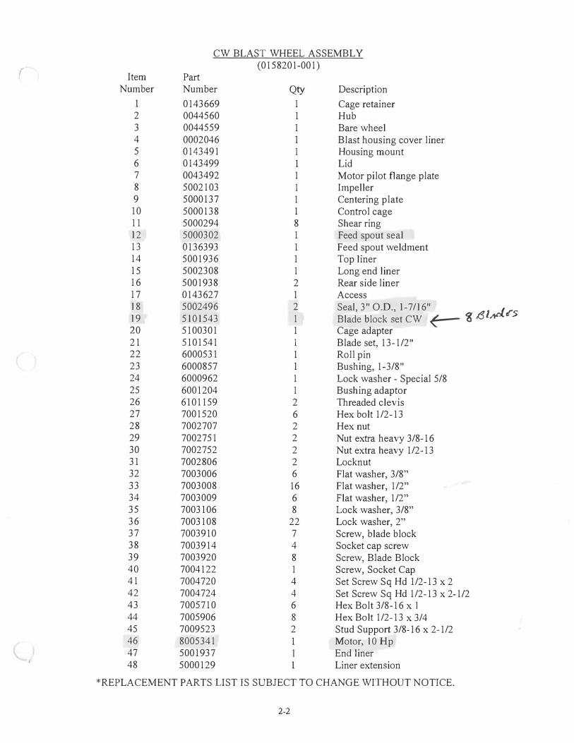
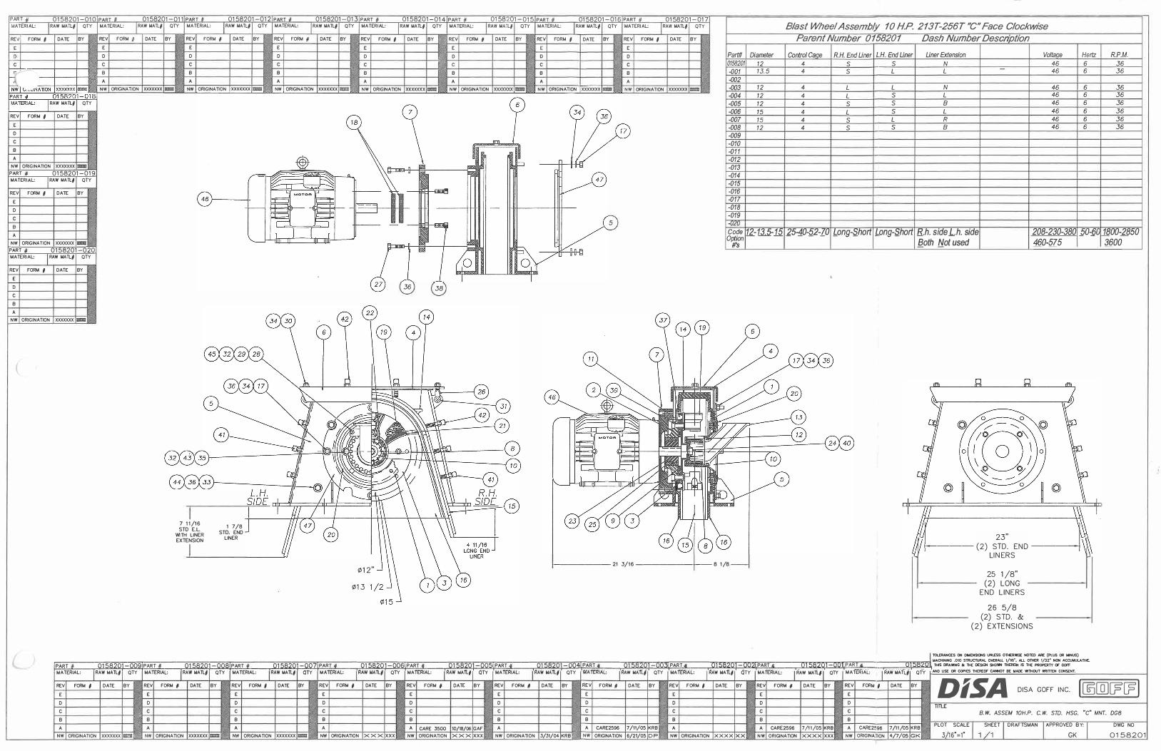
CW BLAST WHEEL ASSEMBLY (0158201-001)
Part Number Qty 0143669 1 0044560 1 0044559 1 0002046 1 0143491 1 0143499 1 0043492 1 5002103 1 5000137 1 5000138 1 5000294 8 5000302 1 0136393 1 5001936 1 5002308 1 5001938 2 0143627 1 5002496 2 5101543 1 5100301 1 5101541 1 6000531 1 6000857 1 6000962 1 6001204 1 6101159 2 7001520 6 7002707 2 7002751 2 7002752 2 7002806 2 7003006 6 7003008 16 7003009 6 7003106 8 7003108 22 7003910 7 7003914 4 7003920 8 7004122 1 7004720 4 7004724 4 7005710 6 7005906 8 7009523 2 8005341 1 5001937 1 5000129
Description Cage retainer Hub Bare wheel Blast housing cover liner Housing mount Lid Motor pilot flange plate Impeller Centering plate Control cage Shear ring Feed spout seal Feed spout weldment Top liner Long end liner Rear side liner Access Seal, 3" O.D., 1-7/16"
.,,d..c5 Blade block set CW � g- 151 Cage adapter Blade set, 13-1/2" Roll pin Bushing, 1-3/8" Lock washer - Special 5/8 Bushing adaptor Threaded clevis Hex bolt 1/2-13 Hex nut Nut extra heavy 3/8-16 Nut extra heavy 1/2-13 Locknut Flat washer, 3/8" Flat washer, 1/2" Flat washer, 1/2" Lock washer, 3/8" Lock washer, 2" Screw, blade block Socket cap screw Screw, Blade Block Screw, Socket Cap Set Screw Sq Hd 1/2-13 x 2 Set Screw Sq Hd 1/2-13 x 2-1/2 Hex Bolt 3/8-16 x I Hex Bolt 1/2-13 x 3/4 Stud Support 3/8-16 x 2-1/2 Motor, 10 Hp End liner Liner extension
*REPLACEMENT PARTS LIST IS SUBJECT TO CHANGE WITHOUT NOTICE.
2-2

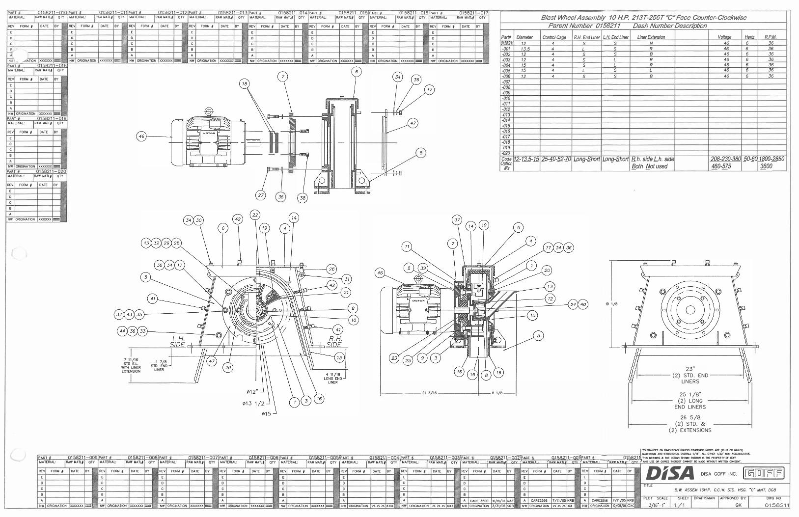
CCW BLAST WHEEL ASSEMBLY (0158211-001)
Item Part Number Number Qty Description
0143669 1 Cage retainer 2 0044560 1 Hub 3 0044559 1 Bare wheel 4 0002046 1 Blast housing cover liner 5 0143491 1 Housing mount 6 0143499 1 Lid 7 0043492 1 Motor pilot flange plate 8 5002103 1 Impeller 9 5000137 1 Centering plate
10 5000138 1 Control cage 11 5000294 8 Shear ring 12 5000302 1 Feed spout seal 13 0136393 1 Feed spout weldment 14 5001936 1 Top liner 15 5002308 1 Long end liner 16 5001938 2 Rear side liner 17 0143627 1 Access 18 5002496 2 Seal, 3 " O.D., 1-7/16" 19 5101544 1 Blade block set CCW 20 5100301 I Cage adapter 21 5101541 1 Blade set, 13-1/2" 22 6000531 1 Roll pin 23 6000857 1 Bushing, 1-3/8" 24 6000962 1 Lock washer - Special 5/8 25 6001204 1 Bushing adaptor 26 6101159 2 Threaded clevis 27 7001520 6 Hex bolt 1/2-13 28 7002707 2 Hex nut 29 7002751 2 Nut extra heavy 3/8-16 30 7002752 2 Nut extra heavy 1/2-13 31 7002806 2 Locknut 32 7003006 6 Flat washer, 3/8" 33 7003008 16 Flat washer, 1/2" 34 7003009 6 Flat washer, 1/2" 35 7003106 8 Lock washer, 3/8" 36 7003108 22 Lock washer, 2" 37 7003910 7 Screw, blade block 38 7003914 4 Socket cap screw 39 7003920 8 Screw, Blade Block 40 7004122 1 Screw, Socket Cap 41 7004720 4 Set Screw Sq Hd 1/2-13 x 2 42 7004724 4 Set Screw Sq Hd 1 /2-13 x 2-1/2 43 7005710 6 Hex Bolt 3/8-16 x I 44 7005906 8 Hex Bolt 1/2-13 x 3/4 45 7009523 2 Stud Support 3/8-16 x 2-1/2 46 8005341 1 Motor, 10 Hp 47 5001937 I End liner 48 5000129 1 Liner extension
*REPLACEMENT PARTS LIST rs SUBJECT TO CHANGE WITHOUT NOTT CE. 2-3
M01192
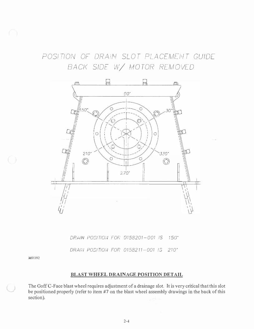
POSI TION OF ORA /;\/ SL O T PLA C[MEf,f T GUIDE
BA CK SIDE lt/ f10 TOR REM O VED
/1 ; L/j
DR/..IN PO:J T/0, J FOF, 0 1 5820 1 - 001 IS
/� �
1 so·
DR,J./,'../ PO:I TIO, J FOF: 0 1 582 1 1 - 00 1 1:; 2 1 0 ·
BLAST WHEEL DRAINAGE POSITION DETAIL
The Goff C-Face blast wheel requires adjustment of a drainage slot. It is very critical that this slot be positioned properly (refer to item #7 on the blast wheel assembly drawings in the back of this section).
2-4

M0I099
CW BLAST WHEEL FRONT VIEW
(Refer to replacement parts list on page 2-2)
2-5

MOI!OO
0)
I
CCW BLAST WHEEL FRONT VIEW
(Refer to replacement parts list on page 2-3)
2-6

M058 1B
BLAST WHEEL SIDE VIEW (Refer to replacement parts list on page 2-2 & 2-3)
2-7

M058IC
®
BLAST WHEEL EXPLODED VIEW (Refer to replacement parts list on page 2-2 & 2-3)
2-8
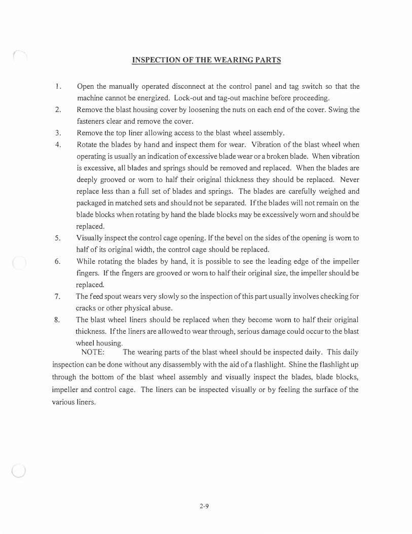
INSPECTION OF THE WEARING PARTS
1 . Open the manually operated disconnect at the control panel and tag switch so that the
machine cannot be energized. Lock-out and tag-out machine before proceeding.
2. Remove the blast housing cover by loosening the nuts on each end of the cover. Swing the
fasteners clear and remove the cover.
3. Remove the top liner allowing access to the blast wheel assembly.
4. Rotate the blades by hand and inspect them for wear. Vibration of the blast wheel when
operating is usually an indication of excessive blade wear or a broken blade. When vibration
is excessive, all blades and springs should be removed and replaced. When the blades are
deeply grooved or worn to half their original thickness they should be replaced. Never
replace less than a full set of blades and springs. The blades are carefully weighed and
packaged in matched sets and should not be separated. If the blades will not remain on the
blade blocks when rotating by hand the blade blocks may be excessively worn and should be
replaced.
5. Visually inspect the control cage opening. If the bevel on the sides of the opening is worn to
half of its original width, the control cage should be replaced.
6. While rotating the blades by hand, it is possible to see the leading edge of the impeller
fingers. If the fingers are grooved or worn to half their original size, the impeller should be
replaced.
7. The feed spout wears very slowly so the inspection of this part usually involves checking for
cracks or other physical abuse.
8. The blast wheel liners should be replaced when they become worn to half their original
thickness. If the liners are allowed to wear through, serious damage could occur to the blast
wheel housing. NOTE: The wearing parts of the blast wheel should be inspected daily. This daily
inspection can be done without any disassembly with the aid of a flashlight. Shine the flashlight up
through the bottom of the blast wheel assembly and visually inspect the blades, blade blocks,
impeller and control cage. The liners can be inspected visually or by feeling the surface of the
various liners.
2-9

BLAST WHEEL HOUSING LINERS
The blast housing liners are identified as follows: top liner, end liners and side liners. These
liners are made of an extremely hard cast alloy. The blast wheel liners are positioned around the
blast wheel to protect the blast wheel housing. Since these liners are in the path of abrasive, wear is
to be expected. Liners should be inspected often to determine when replacement is necessary. All
liners should be inspected on a regular basis. If the liners are allowed to wear through, the housing
itself will quickly develop wear holes causing abrasive leakage on and around the machine.
ALWAYS TURN THE POWER OFF PRIOR TO LINER INSPECTION. Lock-out and tag-out
before proceeding.
The top liner is located in the uppermost section of the housing and is held in place by the
housing cover. The side liners are located in the front and back sides of the housing. The end liners
are located in the right and left ends of the blast wheel housing. The end liners are a slip fit between
the side liners.
TOP L INER
r;/
oi /�ct
END E N D
LI NER L INER
M03 1 1 B
2-10

BLADES
The blades used in Goff airless blast wheel have been weighed and matched at the factory to
insure minimum vibration of the blast wheel assembly. The blades should always be replaced in
matched sets. Partial replacement will result in excessive vibration.
The blades should be checked on a regular basis for wear and breakage. Although a set of
blades may be wearing evenly and may not be causing any abnormal vibrations, they should not be
allowed to wear all the way through. Holes in the blades will allow abrasive to enter the area in back
of the blades causing wear on internal blast wheel parts. This will cause the blast wheel to vibrate as
well as disrupt the quality of blast. If a new set of blades will not remain on the blade blocks when
rotated by hand, the blade blocks are worn and will require replacement.
-,
OLD BLADE N E \1\1 B LADE
M0036
2-11
CHECKING THE ROTATING ASSEMBLY FOR BALANCE AND NOISE
The blast wheel assembly should always run smooth with very little vibration or noise.
Excessive vibration of the blast wheel or unusual noise during operation should be investigated
immediately. Vibration is an indication of an "out of balance" wheel. An "out of balance" blast
wheel is the result of worn or broken blades, blade blocks, impeller, and bare wheel or damaged
internal parts. When investigating an "out of balance" wheel, the blades should be inspected first,
followed by impeller, blade blocks and the bare wheel.
Damage to the internal rotating parts of the blast wheel usually occurs when blades are
allowed to be worn through or broken and abrasive enters the area behind the blade. To inspect and
replace the blades and other parts of the rotating assembly, it will be necessary to partially or
completely disassemble the blast wheel depending on the cause and remedy of the vibration or noise.
Motor failure or improper motor rotation could also cause excessive vibration or noise. Any
motor repairs or replacements should be done by a qualified electrical serviceperson.
2-12
C-FACE BLAST WHEEL MAINTENANCE
WHEEL DISASSEMBLY 1. Ensure power is disconnected following OSHA approved "LOCK-OUT TAG-OUT"
procedure.
2. Remove the blast housing cover (Item 6) (refer to illustrations on page 2-4 and 2-5) by
loosening the nuts (Item 30) on each end of the cover, swing the fasteners (Item 26) clear and
remove the lid.
3. Lift the top liner (Item 14) out.
4. Remove the feed spout (Item 13) by removing the two 3/8" hex nuts (Item 28) holding it in
place.
5. Remove the two 3/8-16 NC x 1 " hex head bolts (Item 43) from the recessed slotted holes in
the cage adapter.
6. Remove the socket head cap screw (Item 40) attaching the impeller to the motor shaft . A
special lock washer (Item 24) locks the screw in place. The control cage (Item 10) and
centering plate (Item 9) can now be removed.
7. The blast wheel blades (Item 21) can now be removed. If the blades are not badly worn, they
can be used again. To aid in the re-installation process, the blades should be numbered I
thru 8 in a clockwise direction before removal. To remove a blade, push it toward the center
of wheel and rotate bottom free of the block (Item 19), then lift it out.
8. Inspect all the parts which have been removed to determine whether they are worn or
damaged to the extent that replacement is necessary.
9. Replace the top liner (Item 14) and housing cover. Bolt cover in place and run blast wheel
assembly (no abrasive).
NOTE: If the assembly runs smoothly and there is no noticeable noise or excessive vibration,
no further disassembly will be necessary. The worn parts can be replaced and the
blast wheel re-assembled. However if vibration or noise is still present it will be
necessary to complete the disassembly and remove the remaining rotating parts.
I 0. Remove the housing cover and lift out the top liner.
1 1. Loosen the compression cap screws (Item 41) on the right and left side of the blast housing.
The end liners (Items 15 & 48) can now be removed through the top or bottom of the blast
wheel housing. Tap the liner gently with a rubber or plastic mallet to ease removal.
12. Remove the four hex head bolts (Item 27) holding the motor mount (Item 7).
2-13

13. This will allow access to the back side to remove the sixteen socket cap screws (Items 37 &
39) holding the blade blocks (Item 19).
14. Hold one of the blade blocks (Item 19) from inside the housing and remove the socket head
screw attaching it to the bare wheel. These screws are located on the inner bolt circle.
Remove each of the remaining blade blocks in the same manner.
15. After all eight blade blocks have been removed; the bare wheel (Item 3) will be free to fall
away from the hub (Item 2). Tilt the bare wheel forward and remove it through the top of the
housing.
16. Remove the two socket set screws in the taper lock bushing. Lightly oil one of the screws
and re-install it in the third hole on the bushing. Be sure the hole is free of abrasive. This
hole is threaded only on the bushing side, the side nearest the motor shaft. Tighten this
screw until the hub releases from the taper lock bushing. If the hub does not release, tap the
face of the hub using a bronze drift and tighten the screw again. When the hub is loose on
the bushing, slide the taper lock assembly off the end of the motor shaft.
17. Remove the hub and key from the motor shaft.
18. Clean the motor shaft and all blast wheel components. Inspect the keyway in the motor shaft
and the key for wear. Check the motor shaft for end play.
19. Inspect front and back side liners (Item 16) for wear. If liners are worn to one half their
original thicknesses, they should be replaced. Remove the retaining bolts holding the front
side liner and remove. Repeat this step on the back side liner. The side liners must be
removed through the bottom of the blast housing.
20. If the blast wheel motor runs smoothly, the blast wheel can be re-assembled. All badly worn
parts should be replaced to assure a smooth running final assembly. If vibration still exists,
the motor may need to be repaired or replaced. Be sure all motor or electrical repairs or
replacements are done by a qualified electrician or serviceperson.
2-14

WHEEL ASSEMBLY
The Goff C-Face blast wheel requires adjustment of a drainage slot. It is critical that this slot
be positioned properly. (Refer to item #7 on the blast wheel assembly drawing showing correct
rotation and drain position in the back of this manual)
1. Replace the key in the motor shaft keyway. The key should fit snugly.
2. Pre-assemble the hub (Item 2) and the bare wheel (Item 3) using Item 39 for alignment. Fit
the shear rings (Item 11) into the counter bore of the threaded hole in the blade block. The
beveled side of the blade block faces toward the center of the hub. Pilot the shear ring into
the bare wheel counter bore and install Items 39 & 37. When all eight blade blocks are
attached, tighten Items 39 & 37 to 80 ft-lb. Attach the motor to the motor mount weldment
(Item 7) and Item 7 to the blast wheel housing. Place the taper lock bushing (Item 23) in the
taper lock of the hub (Item 2). Align the taper lock assembly with the two opposite threaded
half holes in the bushing.
3. Place the rear side liner in position. Center the liner around the motor shaft and bolt in place.
4. Slide the taper lock bushing over the end of the motor shaft (Item 46) with the key properly
aligned with the keyway in the bushing.
5. Lightly oil the two set screw threads. Start the set screws in the holes which are
diametrically opposite each other. Position the face of the bare wheel 1//4" from the face of
the rear side liner.
6. Install the front side liner making sure it is aligned with the rear side liner. This alignment is
essential for the top liner and end liners to seal correctly.
7. Place the cage retainer (Item 4 7) on the housing (Item 5) centering it with the large center
hole of the housing front. Attach the cage adapter (Item 20) to the cage retainer (Item 4 7)
using two 3/8-16 NC x l " hex head bolts (Item 43) on the outer bolt circle.
8. The blades (Item 21) should be installed in a clockwise direction. Attach the blades to the
blade blocks (Item 19) as illustrated on page 2-4 (CW) or 2-9 (CCW).
9. Install the centering plate (Item 9) over the end of the motor shaft.
10. Place the control cage (Item 10) inside the cage adapter. The notch in the outside rim of the
control cage (Item 10) should be facing 180 ° away from the shot pattern.
11. Install the impeller (Item 8) inside the control cage matching up the notches in the impeller
with the lugs on the centering plate (Item 9). Install 5/8-11 NC x 1-1/2" socket head cap
screw (Item 40), and the special lock washer (Item 24) in the threaded motor shaft. Block
2-15
the blast wheel rotation with a wooden block and tighten the screw (Item 40) to 60 ft-lbs
of torque.
1 2. The control cage (Item 10) can now be adjusted and bolted in place. The control cage is held
in place by two 3/8-16 NC x l " hex head screws (Item 43) with flat and lock washers (Items
32 & 35). The screws and washers should be installed in the two recessed slotted holes in
the cage adapter (Item 20) at the 3:00 and 9:00 position. Move the assembly up and down
and side to side until the spacing between the impeller and the control cage is equal all
around. Rotate the blades by hand to check for cage clearance. Repositioning of the cage
adapter (Item 20) and maintenance access to obtain proper cage clearance may be necessary.
Tighten the two 3/8" bolts (Item 43) to hold the assembly in place.
13. Rotate the blast wheel assembly by hand and check for noise or binding.
14. Install top liner (Item 14) and replace the blast housing cover (Item 6).
15. The end liners are designed to slip fit between the front and rear side liners. When properly
installed, a ship lap j oint is provided between the top liner and end liners.. The end liners
should be placed in the bottom of the housing, according to the blast wheel assembly
drawings in the back of this section for correct orientation due to clockwise or counter
clockwise rotation. When end liners are in place, tap lightly with a plastic mallet to insure
proper fit against the top liner. Tighten the compression cap screws to hold end liners in
place.
16. Install the two support studs (Item 45) into cage retainer. Make sure the studs do not extend
past the cage retainer into the blast wheel area. Install the two 3/8" heavy hex nuts (Item 29)
followed by the two washers (Item 32).
17. Inspect the feed spout seal (Item 12) and replace if necessary. Slide the slotted ears of the
feed spout (Item 13) into place over the two support studs (Item 45) and fix it place using
two flat washers, two lock washers and two 3/8" hex head nuts.
18. Rotate the blast wheel assembly by hand and check for noise or binding.
19. After installation of the abrasive valve the blast wheel will be ready for operation.
(Instructions on abrasive valve adjustment are in this section)
20. Proper rotation of the blast wheel motor should always be checked during initial installation;
after any change to electrical supply lines, electrical circuits or blast wheel motor. The blast
wheel should always rotate so that the abrasive is discharged from the front or face of the
blades. Whenever the blast wheel is started for the first time be sure to j og (momentarily
start and stop) the blast motor to insure that the direction of rotation is correct and that the
2-16

positioning of the blades, cage and impeller are correct. Following the jog test, run the
wheel "no load" test (no abrasive) checking for noise or vibration. The unit should run
quietly with little or no vibration.
21. Always check the blast pattern after installation of a new set of blades. (Information on blast
pattern test and adjustment are in this section)
2-17

l
ABRASIVE CONTROL VAL VE
The Goff airless blast wheel assembly is equipped with a totally enclosed abrasive control
valve. Correct adjustment of the control valve is essential for maximum cleaning efficiency and
maximum blast motor life.
The abrasive flow adjustment is determined by the blast wheel motor. (To determine the full
load rating of the motor, check the motor manufacturer's nameplate.) To obtain maximum blast
wheel efficiency, the motor should run at "full load" amperage during the blast cycle.
When the blast wheel motor is started, the ammeter indicator will go to the extreme right side
of the dial until the blast wheel has attained maximum speed. The indicator will then drop back to
normal "no load" amperage. This "no load" reading can serve to indicate the presence of motor or
bearing trouble in future operation. When the blast wheel is running true, the ampere reading should
be constant and steady. Any severe fluctuations can be interpreted as an indication of bearing
trouble, "drag" in some moving parts of the blast wheel, motor trouble, or electrical supply
variances.
While the machine is in actual operation, any fluctuations in the ammeter reading should be
investigated. Changes could indicate shortage of abrasive, stalled elevator, clogged screen, or
foreign objects in the impeller. The ammeter serves as a prime indicator of proper or improper
operation.
As the abrasive valve is opened the amperage load will increase. The valve should be set so
that the motor will draw maximum rated amperage or run at full load. Always run the blast motor at
full load (never overload). Monitor and adjust amperage as necessary.
The abrasive control valve is operated by an adjustable air cylinder. The cylinder has an
adjustable bolt mounted in the end of the air cylinder. By adjusting this bolt, in or out, you can
increase or decrease amperage. To increase amperage, loosen the jam nut on the bolt adjustment and
back the bolt out until desired amperage is obtained. Re-tighten the jam nut. To decrease amperage,
the bolt should be tightened.
2-18

ABRASIVE VAL VE (0105763)
Item Part Number Number Qty Description
1 7002832 I Hex Nut UNC 1/4-20 2 5002058-001 1 Butterfly disc - Heat treated 3 5000121 I Insert 4 5000152 1 Lever 5 0003943 1 Shaft 6 5 100103 1 Valve Body 7 6000136 1 Air cylinder 8 5 1 00190 1 Cylinder mount bracket 9 6000142 1 Clevis rod 10 6000936 2 Ring retainer 11 6001165 2 Fitting 12 7008878 2 Screw 10-24 13 7000912 1 Hex bolt 1 /4-20 1 4 7003004 2 Flat washer 1 /4"
* REPLACEMENT PARTS LIST IS SUBJECT TO CHANGE WITHOUT NOTICE.
L
2-19
ADJUSTING AND CHECKING THE BLAST PATTERN
The appropriate adjustment of the blast pattern is of the utmost importance. A poor
adjustment will not only reduce cleaning efficiency but also increase maintenance and replacement
costs. A blast pattern test should be made when the equipment is first put in operation; when any
decrease in blast efficiency is noted; after replacement or major maintenance have taken place; if a
change is made in the size or type of abrasive material used. Goff recommends, as a good
preventive maintenance measure, that the blast pattern be tested on regular basis. Only the blast
wheel and abrasive recycling system should be operating during a pattern test.
The "hot spot" is that area of the work surface receiving the greatest po1tion of the abrasive
blast. It is visible by the discoloration caused by frictional heat. The "hot spot" should be directed
toward the center of the blast chamber to give the most effective cleaning pattern. If not properly
directed, abnormal wear of the equipment and pa1ts could occur.
To check location of the hot spot, place a painted metal plate (both sides) in the direct path of
the blast pattern of one blast wheel pod at the work height position. Start machine as normal. Blast
the plate at the average speed of 6-l OFPM, and then visually locate the "hottest spot". Gloves
should always be worn during the pattern test. The plate after blasting will be very hot and care
should be taken when handling. The abrasive pattern is delivered in a clockwise and counter
clockwise motion covering the top and bottom of the plate. Never attempt to operate a clockwise
blast wheel or a counter-clockwise blast wheel in the opposite direction from which it was
designed.
The control cage, located at the center of the blast wheel, receives the abrasive from the
storage hopper through the feed spout. The control cage, through the location of its opening,
controls the point of delivery of the abrasive to the blast wheel blades. If the notch in the control
cage is set in a 12 o'clock position then each blade will pick up abrasive at this point and deliver it in
a downward thrust at a point below the blast wheel (approximately 6 o'clock). The point of delivery
may vary with different types and sizes of abrasive.
To adjust the blast stream, "hot spot", the control cage must be rotated clockwise or counter
clockwise. The notch in the cage should always be facing approximately 1 80 · away from the blast
pattern. Rotating the control cage in a clockwise direction will move the "hot spot" toward the left
side of the blast chamber, moving the control cage in a counter-clockwise direction moves the "hot
spot" to the right. Initial adjustment should begin with the notch in the 12 o'clock position. Final
2-21

adjustment will usually be less than l " from this point.
The blast pattern is always set during factory testing prior to shipment, but testing is not
always done with the same type and size of abrasive which will be used at the customer's facility.
Therefore, the pattern must always be checked at initial set-up under the condition the equipment
will be operating.
2-22
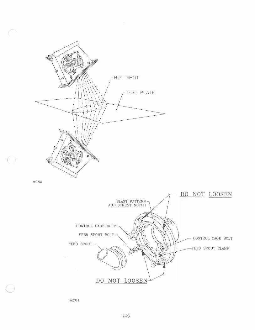
M0718
BLAST p ADJUSTMENT
A TTERN NOTCH
CONTROL CAGE BOLT
FEED SPOUT BOLT
FEED SPOUT
M0719
Ql DO NOT LO OS E:'-J
2-23
DO NOT LOOSEN
.� CONTROL CAGE BOLT
FEED SP OUT CLAMP
PAR T 0 1 5 8 201 - 0 1 0 PART 0 1 58201 - 0 1 1 PART 0 1 58 2 0 1 - 0 1 2 PART 01 58201 - 0 1 3 PART 01 5 8 2 0 1 - 0 1 4 PART 01 58201 - 0 1 5 PART 01 5820 1 - 0 1 6 PART 0 1 582 0 1 - 01 7
MATER I AL: RAW MATL# QTY MATER IAL: RAW MATL# QTY MATERIAL: RAW MATL# QTY MATERIAL: RAW MATL# QTY MATER IAL: RAW MATL# QTY MATER IAL: RAW MA TL# QTY MATER IAL: RAW MATL# QTY MATERI AL: RAW MATL# QTY Blast Wheel Assembly 10 H.P 213T-256T "C" Face Clockwise REV FORM # DATE BY
C
RAW MATL# QTY
REV FORM # DA TE BY
D C
B
A
NW ORIGINATION XXXXXXX 1111111
PART 0 1 5 8 2 0 1 - 0 1 9
MATER IAL: RAW MA TL# QTY
REV FORM # DA TE BY E D
A
NW ORIGINATION XXXXXXX 1111111 PART 0 1 5 82 0 1 - 0 20 MATERI AL: RAW MATL# QTY
REV FORM # DATE BY E
C
B
A
NW ORIGINATION XXXXXXX 1111111
(
REV FORM D DATE BY E D C B A
NW ORIGINATION xxxxxxx 1111111
REV FORM I DATE E D C B A
NW ORIGINATION xxxxxxx
7 1 1 /1 6 STD E.L
\\l TH LINER EXTENSION
1 7/8 STD. END
LINER
BY REV FORM # DATE BY E D C B A
1111111 NW ORIGINATION xxxxxxx 1111111
REV FORM # E D C B A
NW ORIGINATION
¢ 1 2"
¢1 3
DATE
xxxxxxx
36
BY REV FORM I
E D C B A
1111111 NW ORIGINATION
38
DATE BY REV
0 C B A
xxxxxxx 1111111 NW
FORM # DATE BY REV FORM # DA TE BY E D C B A
ORIGINATION xxxxxxx 1111111 NW ORIGlNATION xxxxxxx IIDIII
5
Parent Number 0158201 Dash Number Description
Part# Diameter Control Ca e R.H. End Liner L.H. End Liner Liner Extension 0158201 12 4 s s N -001 13. 5 4 s L L
-002 -003 12 4 L L N -004 12 4 L s L
-005 12 4 s s B
-006 15 4 L s L
-007 15 4 s L R
-008 12 4 s s B
-009 -010 -01 1 -012 -013 -014 -015 -016 -017 -018 -019
Code 12-13.5- 15 25-40-52-70 Long-Short Long-Short R.h. side L.h. side Opt/on - - - - - - - - - - - Both Notused #s - -
23"
Volta e Hertz R.P.M. 46 6 36
46 6 36
46 6 36
46 6 36
46 6 36
46 6 36
46 6 36
46 6 36
208-230-380 JO-§ 1800-2850 460-575 3600
i---- (2) STD . END -----i LIN ERS
f-------- 21 3/1 6 -------+-- 8 1 /8
25 1 /8" (2) LONG
END L INERS
26 5/8 (2) STD . &
(2 ) EXTENS IONS
TOL£RANC£S ON DIMENSlc>IS UNLESS OTHER'MSE NOTED AA£ (PL.US � t.lNUS)
�---------�----------�-----��-�=�-----=---=------=---�-----==--��------=--=----------�----------�-------�=.,,..,j MAOIINING .010 SlRUCT\JRAL OVERALL 1/115•, All OTHER 1/32. HOH ACCUMULA11'¥E.
.,P�A�RT'cc"---""T::'0�1=5�8�2�0
'-/1_-�0�0=9
'tP�AR
-'-::'::T
c"c-:-,---r::0=1:','
5=8,.,
2c-'
0",
1r-�0":'
0=8"+-
P�AR-::
T::='c--.::"0
':'1=5=8
-=2=0+1 -...... 0=0�7+P�A
'--:
R::::T ='":-,--,.,,0
",1':'
5'-:'
8�2�0'-/
1_-�0':'
0�o't
P�A�R::':T
c::"c-:-:----r::"0
:':1 =5=8
""-20=1
t----,
0"':
0=5=-r,
P�AR'-':
T':=---""T::'0
'-:'1=5=8
'-';2=041_-�0=0�4
-tP:c
A":
R:::T
c"c-:-,---r::0�1=5=8
,.,2,,_.,
0..,
1�-�0=0=3'+,'
PA�R::':
Tc::"c-:,-----r::"0�1 5=8=2
=-0�1
;--...,
0=0=2"4-,
P�AR'-':
T':=-
----rc,-=0�1 5=8"'
2�0,.
1�--0=0�1+P�A�R:::T
c"c-:--:---,..,-,,-=-'0
'-i1=5=8-=
2=0,1 1HJS CftA.,NC " 1HE OESCN SHO"' THEREIN JS THE PROPERTY <F corr MATERIAL: RAW MATL# QTY MATERIAL: RAW MATL# QTY MATERIAL: RAW MATL# QTY M ATERIAL: RAW MATL# QTY MATERIAL: RAW MATL# QTY MATERIAL: RAW MATL# QTY MATER IAL: RAW MATL# QTY MATERIAL: RAW MATL# QTY MATERIAL: RAW MATL# QTY M ATER IAL: RAW MATL# QTY ANO USE OR COPIES THERE<F CANNOT BE MADE .,THOUT ..,TTIN CONSENT.
REV FORM # DATE BY E
REV FORM # DATE BY REV FORM # DATE BY REV FORM # DATE BY REV FORM # DATE BY REV FORM # DATE BY REV FORM # DATE BY REV FORM # DATE BY REV FORM # DATE BY REV FORM # DATE BY
DiSA DISA GOFF INC. l[]JrnJcscsl E E E E E E E E D D D D D D D D D D
TITLIE C C C C C C C C C C B. W. ASSEM 10H.P. C. W. STD. HSG. "c" MNT. 0GB
B B B B B B B B B B A A A A A CARE 3500 10/18/06 GAF A A CARE2596 7/11/05 KRB A A CARE2596 7/1 1 /05 KRB A CARE2596 7 /1 1 /05 KRB PLOT SCALE SHEET DRAFTSMAN APPROVED B Y: DWG NO
NW ORIGINATION XXXXXXX IIXt'll NW ORIGINATION xxxxxxx IIDIII NW ORIGINATION xxxxxxx 1111111 NW ORIGINATION X X X XXX NW ORIGINATION X X X XXX NW ORIGINATION 3/31/04 KRB NW ORIGINATION 6/21/05 D P NW ORIGINATION XXXX xx N W ORIGINATION xxxx XXX NW ORIGINATION 4/7/05 GK 3 1 6"=1" GK 0 1 5 8 2 0 1
PART 01 5821 1 - 01 0 PART 01 5821 1 - 01 1 PART 01 5821 1 - 01 2 PART 01 5821 1 - 01 3 PART 01 5821 1 - 01 4 PART 01 5821 1 - 01 5 PART 01 5821 1 - 01 6 PART 01 5821 1 - 01 7 MATERIAL: RAW MATL# QTY M ATERIAL: RAW MATL# QTY f.lATERIAL: RAW MATL# QTY MATERIAL: RAW MATL# QTY MATERIAL: RAW MATL# QTY MATERIAL: RAW MATL# QTY f.lATERIAL: RAW MATL# QTY MATERIAL: RAW MATL# QTY
REV FORM # DATE BY REV FORM f DATE BY REV FORM # DATE BY REV FORM # DATE BY REV FORM # DATE BY REV FORM # DATE BY REV FORM # DATE BY REV FORM # DA TE BY E E E E E E E
D D D D D D D C C C C C C C C
� B B B B B B B
A A A A A A A A
NW I ... 1.1\/ATION xxxxxxx 1111m NW ORIGINATION xxxxxxx 1111m NW ORIGINATION xxxxxxx 1111m NW ORIGINATION xxxxxxx 1111m NW ORIGINATION xxxxxxx 1111m NW ORIGINATION xxxxxxx mxm NW ORIGINATION xxxxxxx 1111m NW ORIGINATION XXXXXXX IXlllll PART 01 5821 1 - 01 8 MATERIAL: RAW MATL# QTY
REV FORM # DATE BY E D C
B
A NW ORJGINA TION XXXXXXX 1111m
PART 01 5821 1 - 01 9 MATERIAL: RAW MATL# QTY
REV FORM # DATE BY E D C
5
Blast Wheel Assembly 10 HP. 213T-256T "C" Face Counter-Clockwise
Parent Number 015821 1 Dash Number Description
Part# Diameter Contro/ Ca e R.H. End Liner L. H. End Liner Liner Extension Volta e Hertz R.P.M. 0158211 12 4 s s N 46 6 36
-001 1 3. 5 4 L s R 46 6 36
-002 12 4 s s B 46 6 36
-003 12 4 s L R 46 6 36
-004 15 4 s L R 46 6 36
-005 15 4 L s L 46 6 36
-006 12 4 s s B 46 6 36
-007 -008 -009 -010 -01 1 -012 -013 -014 -015 -016 -017 -018 -019
B
Code 12-13.5- 15 25-40-52-70 Long-Short Long-Short R.h. side L.h. side Optfon - - - - - - - - - - - Both Notiised
208-230-380 JO� �00-2850 NW ORIGINATION XXXXXXX 1111m
#s - - 460-575 3600 PART 01 5821 1 - 020 MATERIAL: RAW MATL# QTY
REV FORM # DA TE BY E D 36
C
B
A NW ORIGINATION XXXXXXX 1111m
l
7 1 1 /1 6 STD E.L.
111TH LINER EXTENSION
1 7/8 STD. END
LINER
¢1 3
19 1 /8
t------- 21 3/1 6 -------+-- 8 1 /8
23" 1----- (2) STD . END ___ ____,
LIN ERS
25 1 /8" (2 ) LON G
EN D L IN ERS
26 5/8 (2 ) STD. &
(2 ) EXTENS IONS
10l£RANCES ON DIMENSlc»,1S U NlESS 01HERWl5£ NOTED ARE (PWS OR MINUS)
�------=-�=------=---�-----=---=�-------------------------------�-------------------------------�-------��,..,....,, MACHINING .010 STRUCTURAL CMRALL 1/115", AU. On£R 1/32• NON ACOJMULATI'fE. PART 01 5821 1 -009 PART 01 5821 1 - 008 PART 01 5821 1 - 007 PART 01 5821 1 - 006 PART 01 5821 1 -005 PART 01 5821 1 - 004 PART 01 5821 1 - 003 PART 01 5821 1 - 002 PART 01 5821 1 - 001 PART 01 5821 1 1HIS MAWING " ™' DESGN SHO'ON THEREIN IS THE PROPERTY DF GOFF
l':M�A:-::TE=R�l,...AL-, --,-:;R=AW.....,MA=:TL
:"#':+-�Q=TY=t,-:M-,-ATE=:'R':-:IA.,...
L:--r::Rc"AW,:"=M=All:"#"c+-�Q=:
TY",=ii':'
"4�A-=TE
==R�IAL-: -,Rc-'A":'W�M�A'=ll�,;-Q,"TY=+M�A:-::TE
:':::R-!',1-,-AL:-·--,-:;R=AW=MA�ll�#-�Q�TY=t�M�A':'TER
,,,...,IA-L·-. -.,,R�A�W=M=A-=ll�,+--Q=TY==rM�A'-':TE
'::-RilA.,,L-, -""T'::'RA�W=MA�TL�,+-�QTY""-''+:-:M7ATE=:'R�IA,-
L:---.:R=AW=M=All.,_,_# ;--Q�TY=rt.1�A-=TE
':-:R�I A,,.L-: -.R�A�W=M�A'=TL�#;-Q=TY=+M�A�TE
'::-R�I A,...L:-- -""T'::'RA�W=MA""ll�,--Q=TY-�M�A==TE
=R':-:IA7L:---.:Rc:-AW"'""MC'CA1l=-,-=Q=TY",'-'t '"D USE OR COPIES THEREOf' CANNOT BE WADE WITHOUT ... TIEH CONSENT.
REV FORM # DATE BY E
REV FORM # DATE BY REV FORM # DATE BY REV FORM # DATE BY REV FORM # DATE BY REV FORM # DATE BY REV FORM # DATE BY REV FORM # DATE BY REV FORM # DATE BY REV FORM I DATE BY
DiSA DISA GOFF INC. l[B[]][?[?I E E E E E E E E D D 0 0 D 0 D D D 0
TITLE C C C C C C C C C C B. W ASSEM 1 0H.P. C.C. W. STD. HSG. -c- MNT. 0GB
B B B B B B B B B B A A A A A A A A 10/18/06 A CARE2596 7/1 1 /05 KRB A CARE2596 7/1 1 /05 KRB PLOT SCALE SHEET DRAFTSMAN APPROVED BY: DWG NO
CARE 3500 GAF NW ORIGINATION XXXXXXX = NW ORIGINATION xxxxxxx mxm NW ORIGINATION XXXXXXX 1111m NW ORIGINATION xxxxxxx mxm NW ORIGINATION xxxxxxx IIDlll NW ORIGINATION X X X XXX NW ORIGINATION X X X XXX NW ORIGINATION 3/31/06 KRB NW ORIGINATION X X X XXX NW ORIGINAllON 10/05/01 GK 3 1 6"=1" GK 01 5821 1

SECTION 3 - CABINET ASSEMBLY
Replacement Parts List - Cabinet Assembly ................................ ................................................ 3- 1 Cabinet - Front View Detail. ................................................................................. ....................... 3-3 Cabinet - Side View Detail .......................................................................................................... 3-4 Cabinet - Plan View Detail ................................... ................................................. ...................... 3-5 Span Assen1bly Detail .................................................................................................................. 3-6 Spinner/Thrust Bearing Detail ..................................................................................................... 3-7 Span Detail ...................................................................................................... ............................. 3-8 Spinner Chamber Drive Assembly - Exploded View .................................................................. 3-9

CABINET ASSEMBLY (0158382)
Item Part Number Number Qty Description
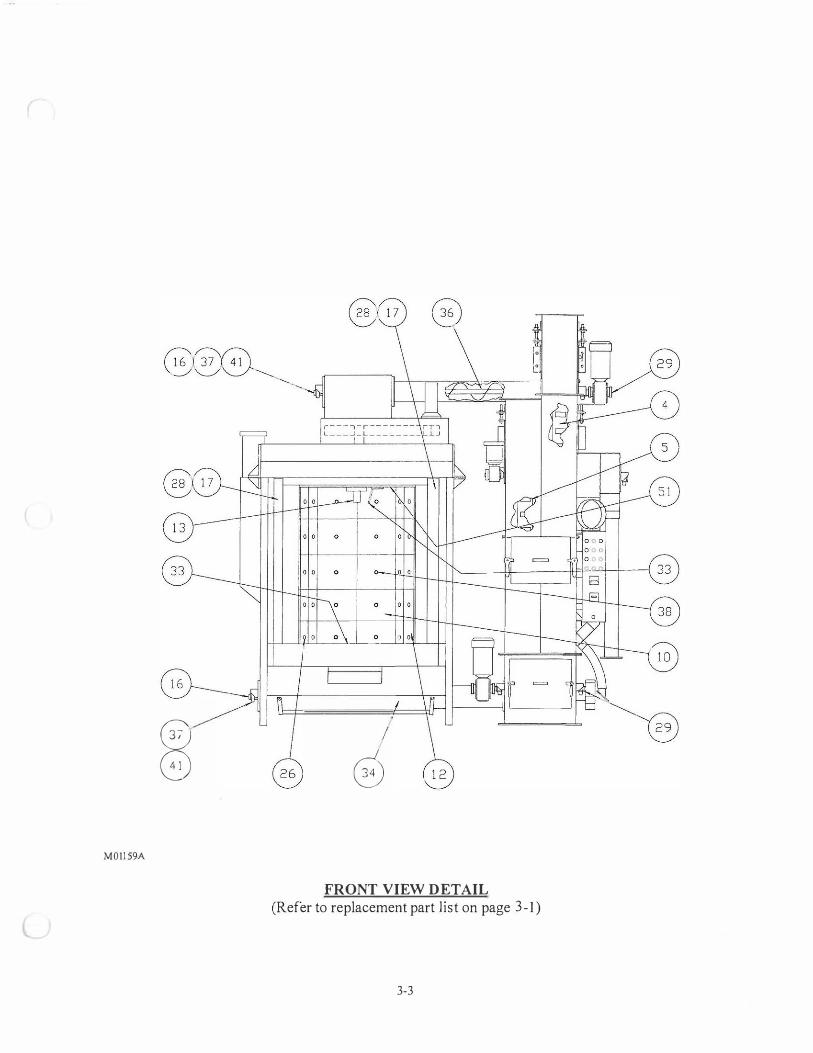
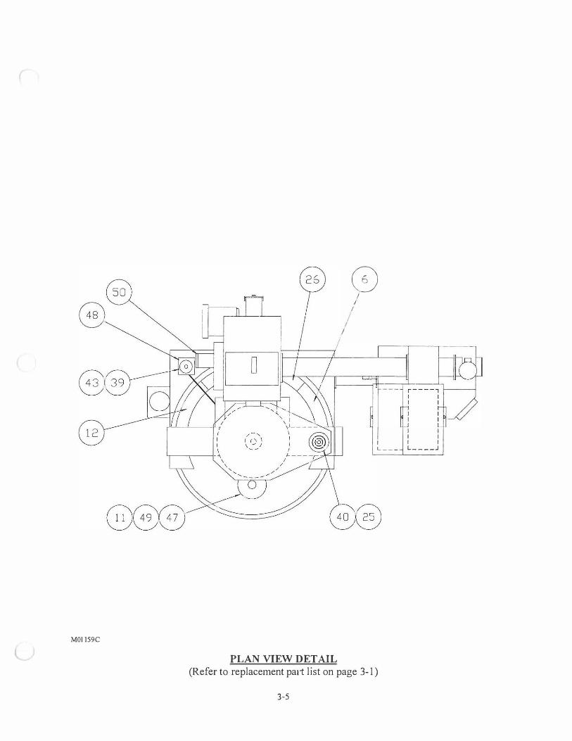
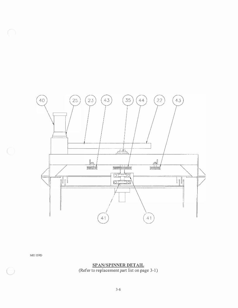
3 6000729 2 Bushing, - Idler 4 0154789 1 Belt assembly - Elevator/Hopper 5 0154788 1 Belt assembly - Elevator/Separator 6 0109714 1 Seal, front right 7 0105763 2 Abrasive valve assembly 8 0158201-001 1 Blast wheel assembly CW 9 0158211-001 1 Blast wheel assembly CCW 10 5001000 40 Cast liner 11 0008784 2 Shaft - Spinner 12 0 109195 1 Seal - Front left 13 0009057-001 2 Support hanger - Heat treated 14 00 18063 1 Shaft - Span/Chamber 15 0010790 1 Bottom stub shaft 3" dia. 16 0015433-002 2 Stub shaft - Top screw 17 0013755 4 Seal 18 6001333 8" Hose 3" dia. 19 0110895 4 Flange adapter 20 6001869 1 Bushing 21 6001495 1 Sprocket HTD 22 6001496 1 Sprocket HTD 23 6001497 1 Belt HTD 24 6001756 1 Bushing, 2" 25 6001868 1 Reducer, 100: 1 26 0 109196 2 Seal - back 28 0014075 2 Liner - side , 29 0015436-001 2 Drive shaft 30 6100554 1 Belt, 5/8" Urethane x 72" lg 3 1 0109058-001 2 Seal ring - heat treat 32 0113084 2 Chamber liner weldment 33 01 13767 2 Deflector weldment 34 01 14017 1 Bottom screw conveyor 35 6000928 1 Bearing, 4-bolt, 3" bore 36 0 123316-001 1 Top screw onveyor 37 5002496 4 Seal, 1-7/16" , 3" OD 38 5000860 24 Cast nut 1/2-13 39 6001285 2 Bushing, 1 -7 /16" bore 40 8002055 1 Motor, 3/4hp 41 6000485 6 Bearing, 1-7/16" 42 6000497 I Bearing - Thrust 3" 43 6000723 1 Sheave, TL, 5.4PD 44 6000724 2 Sheave, TL, 9.4PD
3-1
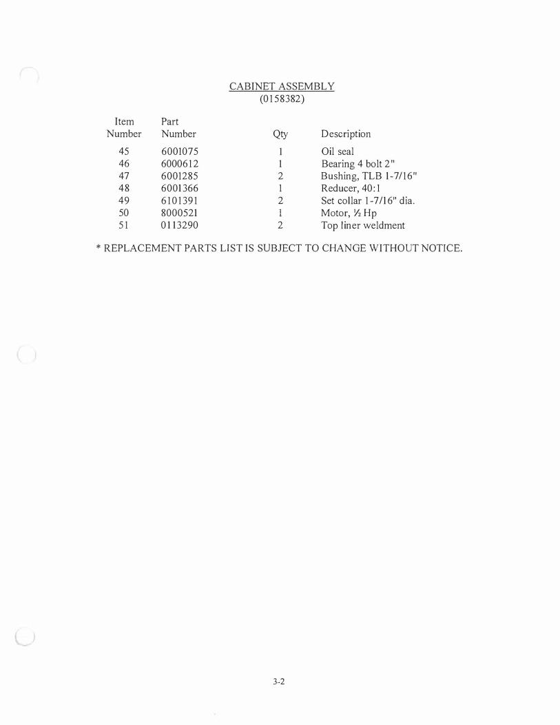
CABINET ASSEMBLY (0 1 58382)
Item Part Number Number Qty Description
45 6001075 1 Oil seal 46 6000612 1 Bearing 4 bolt 2" 47 6001285 2 Bushing, TLB 1-7/16" 48 6001366 1 Reducer, 40: 1 49 6 10 1 39 1 2 Set collar 1 -7/16" dia. 50 8000521 1 Motor, ½ Hp 5 1 0 1 13290 2 Top liner weldment
* REPLACEMENT PARTS LIST IS SUBJECT TO CHANGE WITHOUT NOTICE.
3-2
M011 59A
0 0
I
0
FRONT VIEW DETAIL (Refer to replacement part list on page 3- 1 )
3-3

MO! 159B
L SIDE VIEW DETAIL (Refer to replacement part list on page 3-1)
3-4
MOl 159C
I I
PLAN VIEW DETAIL
0 I
I
I I
I I I L _ _ _ L _ _ _ _ .J
(Refer to replacement pa1t list on page 3-1)
3-5
MOl 159D
I I
G
SP AN/SPINNER DETAIL (Refer to replacement part list on page 3- 1 )
3-6

MOl 159E
l
� = I
CHMH BER
E,:'=-=-=-=-�==:,·;--, ------�@
THRUST BEARING DETAIL (Refer to replacement part list on page 3- 1 )
3-7

M01 159F
SPAN DETAIL
l (Refer to replacement part list on page 3- 1 )
3-8

@)
G
M0 1 159G
CHAMBER DRIVE ASSEMBLY DETAIL (Refer to replacement part list on page 3-1)
3-9
SECTION 4 - ABRASIVE RECYCLING SYSTEM
Replacement Parts List - FES Assembly .............................................. . . . . . . . . . . . . . . . . . . . . . . . . . ...... ........ 4-1 Elevator Top Section .......................... . . . .. . ............... ... . ................. ........... .... . . . . . ........................... 4-2 Replacement Parts List - Elevator Separator Assembly . . . . . . . . . . .. . . . . . ...................................... . ...... 4-3 Elevator Separator Assembly - Front View . . . . ....... ... . ............ . . .. .. ........ . . . . . . . . . . . . . ............. .. . . . .. . . . . . . . 4-4 Elevator Separator Assembly .... . . . . . . . . .......... . . .................. ................ . .............. .. ............. ............... 4-5 Adjustment of the Abrasive Separator ............. . . . . . . . .... . . ........... ... . ... . . . . . . ........................ ............... 4-6 Abrasive Separator and Air Flow Detail. ....... ................................... .. . . . . . ....... . . . . . . . . . . . . . . . . . . ........... 4-6 Replacement Parts List - Elevator Bottom Section . . . . ......... . .............. . . . . . . . . . . . . . . ................ ........... 4-8 Replacement Parts List - Abrasive Valve Assembly ... . . ..................... . . . . . . . . ...... ............. .. . . . . . . .... 4-1 1 Abrasive Storage Hopper ........................... ....... .............................. . . . ...... ..................... ..... . . . ..... 4-12 Auto Abrasive Adder Hopper . . . .... . . . . . . . . . . . ......... ....... . . .... . . . . .. . ......... . . . ........ . . . . . ..... . . . . . . . ................ 4-12 Elevator Belt Maintenance ................................ ......................... ..................... .. . . . . . . . . . . . . . . . ...... . . . . 4-13 Abrasive .... . . . . . . .. . . ... . . . ............ .......... . . . ............... . . . . . . . ..................... ...... . . . . ...... . . . . .............. . . . . . . ..... 4-14 Steel Abrasive Sizes and General Applications . ............................................ . . ....................... . . . 4-15

r ,.-----.. ,., \ 6j 5 > 4 ;
... _......, ... ,...
8---tt----------M01 161
Item Part Number Number
1 0 1 54722 2 0 154721 3 0 154723 4 0 1 54793 5 7002709 6 7003 108 7 0 1 54788 8 0 1 54789 9 6 100 1 10 10 600 1799 1 1 6003642
FES ASSEMBLY (01 54720)
Qty Description
1 Elevator bottom assembly 1 Elevator separator assembly 1 Elevator top assembly 1 Adder hopper
14 Hex nut 1/2- 1 3 14 Lock washer 1/2" 1 Separator belt 1 Hopper belt 2 Rubber neoprene 1/16 x 3 x 36 4 Clamp 1 Duct
* REPLACEMENT PARTS LIST IS SUBJECT TO CHANGE WITHOUT NOTICE.
4-1
- . , l )
MDI 164
0
2
. 1) 0
�-
� .i) \..:J
I L:J 0
l
o
•
j
g -
0 �
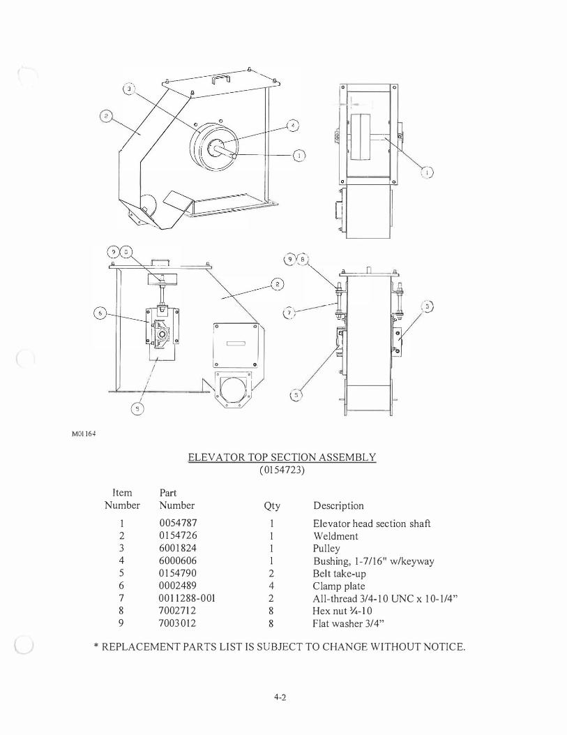
ELEV A TOR TOP SECTION ASSEMBLY (01 54723)
Item Part Number Number
1 0054787 2 0 1 54726 3 600 1 824 4 6000606 5 0 1 54790 6 0002489 7 00 1 1288-001 8 7002712 9 7003012
Qty
1 1 1 I
2 4 2 8 8
Description
Elevator head section shaft Weldment Pulley Bushing, 1-7/16" w/keyway Belt take-up Clamp plate All-thread 3/4- 10 UNC x 10-1/4" Hex nut ¾-10 Flat washer 3/4"
* REPLACEMENT PARTS LIST IS SUBJECT TO CHANGE WITHOUT NOTICE.
4-2
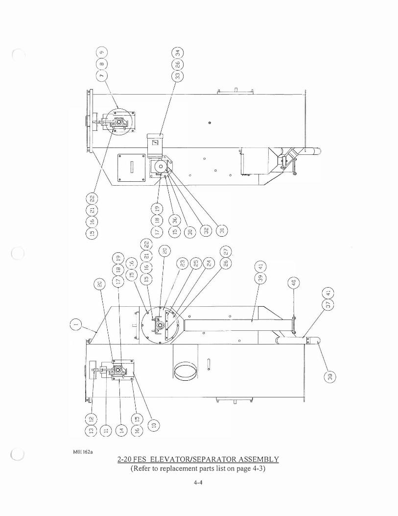
ELEVATOR SEPARATOR ASSEMBLY (0 1 54721)
Item Part Number Number Qty Description
1 0 154757 1 Elevator/Separator weldment 2 0 102935 2 Baffle weldment 3 0106 149 2 Refuse gate 4 000293 1 2 Spreader gate 5 0 1 03 1 44 2 Swinging gate weldment 6 0 1 50076 1 Rotary screen weldment 7 0003767 1 Elevator leg shaft 8 6001244 1 Pulley 9 6000606 1 Bushing, 1-7 / 16" w/keyway 1 0 0103597 2 Take-up elevator belt 1 1 00 1 1 288-001 2 Take-up Screw 12 7002712 8 Hex nut 3/4- 10 1 3 7003016 8 Flat washer 3/4" 14 0002489 4 Clamp plate 15 7003 108 34 Lock washer 1/2" 16 7002709 28 Hex nut 384-10 1 7 0024016 3 Seal bearing 18 5002496 3 Seal, 1 -7/16" 19 0002438 3 Retainer seal 20 6000485 4 Bearing, 1-7 / 16" 2 1 7005924 8 Hex bolt 1/2-13 x 2-1/2" 22 7003008 8 Flat washer 1/2" 23 0 1 02833 1 Screen weldment 24 0002936 1 Rotary screen curtain 25 0002509 1 Retainer curtain 26 7003 106 1 2 Lock washer 3/8" 27 7002707 4 Hex nut 3/8-16 28 600 1295 4 Ball spring plunger 29 7002807 8 Lock nut 1/2-13 30 0 102905 1 Bearing hanger weldment 3 1 0054772 1 Reducer mount 32 600 1381 1 Reducer, 50: 1 33 8001032 1 Motor, 1/2 HP 34 7005712 4 Hex bolt 3/8- 16 x 1 - 1 /4" 35 7005710 1 Hex bolt 3/8-16 x 1 " 36 7005906 6 Hex bolt 1/2-1 3 x 3/4" 37 6 10 13 12-001 1 Tubing, flex steel 3 8 0 10301 3 1 Dribble valve assembly 39 6 1 01252-001 1 Tubing, flex steel 40 0 103 183 1 Dribble valve assembly 4 1 7000762 12 Screw traxx 42 0 103208-001 1 Elevator cover weldment 43 600 1 1 85 2' Weatherstrip 42 0 1 03208-001 1 Elevator cover weldment
* REPLACEMENT PARTS LIST IS SUBJECT TO CHANGE WITHOUT NOTICE.
4-3
l MO! 162a
ffi
� -------1------L=::'.:'.:=::'.'.L------1
0
0
0 0
0
2-20 FES ELEV A TOR/SEP ARA TOR ASSEMBLY (Refer to replacement parts list on page 4-3)
4-4
®

,.
l.
_.,,,,,.. .. - 1 '-, ' -----
0
M01 162B
®
0
2-20 FES ELEV A TOR/SEP ARA TOR ASSEMBLY (Refer to replacement parts list on page 4-3)
4-5
< [ I
::-I
L_
C: 1---i
f-LJ w (/')
l
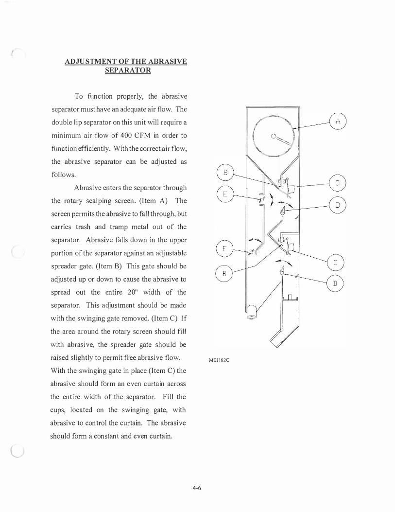
ADJUSTMENT OF THE ABRASIVE SEPARATOR
To function properly, the abrasive
separator must have an adequate air flow. The
double lip separator on this unit will require a
minimum air flow of 400 CFM in order to
function efficiently. With the correct air flow,
the abrasive separator can be adjusted as
follows.
Abrasive enters the separator through
the rotary scalping screen. (Item A) The
screen permits the abrasive to fall through, but
carries trash and tramp metal out of the
separator. Abrasive falls down in the upper
portion of the separator against an adjustable
spreader gate. (Item B) This gate should be
adjusted up or down to cause the abrasive to
spread out the entire 20" width of the
separator. This adjustment should be made
with the swinging gate removed. (Item C) If
the area around the rotary screen should fill
with abrasive, the spreader gate should be
raised slightly to permit free abrasive flow.
With the swinging gate in place (Item C) the
abrasive should form an even curtain across
the entire width of the separator. Fill the
cups, located on the swinging gate, with
abrasive to control the curtain. The abrasive
should form a constant and even curtain.
MOI 162C
4-6
./ \ t c� I
' -;? 11---,.-1-,---,

As the abrasive falls down to the next separator section, air is being pulled through the
curtain of abrasive by the dust collector. This air flow removes the sand and fine contaminants
from the abrasive. The size and amount of contaminant removed is determined by the
adjustment of the refuse gate (Item D) and the air baffle (Item E). The refuse gate and the air
baffle must be set in combination in order to function properly. Size and type of abrasive used
will determine correct setting. Adjusting the refuse gate toward the falling curtain of abrasive
will adjust the size and quantity of particle removed from the abrasive. Moving the refuse gate
away decreases the size and quantity of particle removed. Adjust the air baffle and refuse gate,
until as much sand and unusable abrasive as possible are removed, but no usable abrasive is
removed.
Adjust upper and lower separator to maximum efficiency and to prolong machine blast unit life.
4-7
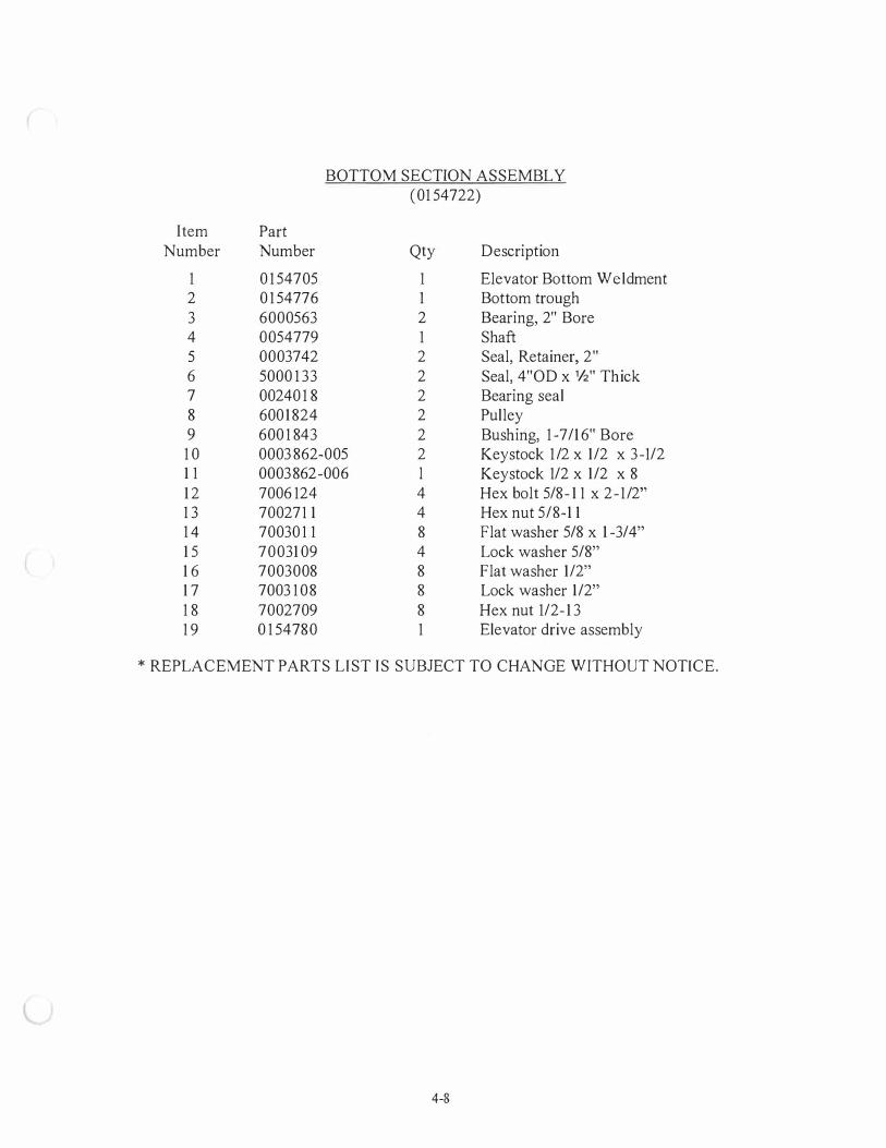
BOTTOM SECTION ASSEMBLY (01 54722)
Item Part Number Number Qty Description
1 0 1 54705 1 Elevator Bottom Weldment 2 0 1 54776 1 Bottom trough 3 6000563 2 Bearing, 2" Bore 4 0054779 1 Shaft 5 0003742 2 Seal, Retainer, 2" 6 5000 1 33 2 Seal, 4"OD x ½" Thick 7 00240 1 8 2 Bearing seal 8 6001824 2 Pulley 9 600 1 843 2 Bushing, 1 -7/16" Bore 10 0003862-005 2 Keystock 1/2 x 1/2 x 3-1/2 1 1 0003 862-006 l Keystock 1/2 x 1/2 x 8 12 7006 124 4 Hex bolt 5/8-1 1 x 2-1/2" 1 3 700271 1 4 Hex nut 5/8-1 1 1 4 70030 1 1 8 Flat washer 5/8 x 1-3/4" 15 7003109 4 Lock washer 5/8" 16 7003008 8 Flat washer 1/2" 17 7003 108 8 Lock washer 1/2" 1 8 7002709 8 Hex nut 1/2-13 1 9 0 1 54780 1 Elevator drive assembly
* REPLACEMENT PARTS LIST IS SUBJECT TO CHANGE WITHOUT NOTrCE.
4-8

M0I I 63A
-=, 0 ;
0 <.,
0 0 0
1 6 1 7 1 8
ELEVATOR BOTTOM ASSEMBLY (Refer to replacement parts list on page 4-9)
4-9

M01163B
. 0 '-,
9
ELEVATOR BOTTOM ASSEMBLY (Refer to replacement parts list on page 4-9)
4-10
4

9
8
M0311E
ABRASIVE VAL VE (01 1481 1)
Item Part Number Number Qty Description
1 7002832 1 Hex nut UNC 1/4-20 2 5002058-001 1 Butterfly disc - Heat treated 3 5000121 1 Valve body insert 4 5000152 1 Lever 5 0003943 1 Shaft 6 5 1 00 103 1 Valve body 7 6000221 1 Air cylinder 8 5100190 1 Cylinder mount bracket 9 6000142 1 Clevis rod
10 6000936 2 Ring retainer 11 6001 17 1 2 Fitting 12 7008878 2 Screw 10-24 13 7000914 1 Hex bolt 1/4-20 x 1-1/2 14 003004 2 Flat washer 1/4"
* REPLACEMENT PARTS LIST IS SUBJECT TO CHANGE WITHOUT NOTICE.
4-1 1
ABRASIVE STORAGE HOPPER
The storage hopper abrasive level should be full at the start up of machine. After the end of
each shift allow the abrasive to recycle back into the hopper. While the abrasive is re-cycling back
keep the blast wheels off and the abrasive control valves to the blast wheel closed. After a few
minutes stop recycling abrasive. Inspect hopper and add abrasive as needed. While the machine is
blast cleaning parts, the abrasive volume in the hopper will decrease until the abrasive is recovered
automatically from the machine. Depending on the machine, it takes the abrasive 15-45 seconds to
be recycled back from the blast wheels to the hopper. Some abrasive will be lost due to abrasive
breaking apart after contact with parts. This unusable abrasive is removed by the air wash separator
making it necessary to replace abrasive periodically. An adequate accumulation of abrasive in the
hopper will not only ensure a steady flow to the blast wheels, but will also prevent wear on the
hopper by keeping the sides of the hopper protected against the abrading action of cascading
abrasive particles. The correct abrasive level in the hopper should be maintained by periodic
additions of new abrasive to compensate for abrasive breakdown.
AUTO ABRASIVE ADDER HOPPER (OPTIONAL EQUIPMENT)
The auto abrasive adder hopper adds abrasive to the machine's abrasive recycling system
while the machine is blast cleaning parts. A sensor in the abrasive storage hopper alerts the auto
abrasive adder hopper's abrasive control valve to add more abrasive into the recycling system when
the abrasive volume in the storage hopper become too low. Some abrasive will be lost in the
cleaning process due to abrasive breaking apart after contacting parts. This unusable abrasive is
removed by the air wash separator making it necessary to replace abrasive periodically. At the end
of each shift make sure the auto abrasive adder hopper is full.
4-12

l
ELEVATOR BELT MAINTENANCE
Belt tension should be checked regularly to insure proper operation of the recycling system.
The following information should be considered when checking belt tension.
1 ) The pulley in the elevator bottom section should rotate constantly without slippage or
hesitation.
2) The unloaded belt should run generally in the center of the elevator casing with
minimum movement from side to side.
3) Elevator buckets should not strike the sides of the casing.
4) It should not be possible to manually slide the elevator belt back and forth across the
face of the pulley when the elevator is stopped. However, the tension on the elevator
belt should not be so great that there is danger of tearing out the splice.
The elevator belt may become stalled or jammed for several reasons.
1 ) If the blasting operation is started without the elevator running.
2) If the elevator belt slips because of improper tension adjustment.
3) If abrasive is added without the elevator system operating.
4) If abrasive is added to the machine at a rate faster than the elevator is capable of
handling.
If a stalled elevator condition exists, the abrasive feed to the blast wheels and all power sources to
the machine should be cut off immediately. It is advisable to use a scoop or scraper for removing
abrasive from a jammed elevator. DO NOT USE YOUR HANDS! The rubber elevator belt in this
jammed condition has been stretched and is probably under tension. At some point, while the excess
abrasive is being removed, the tension in the stretched belt will be released causing the pulley to
rotate very rapidly in the reverse direction. Serious personal injury could result if a hand or forearm
were in the path of the rotating elevator buckets.
4-13
ABRASIVE
The abrasive has a major influence on the efficiency of cleaning and on the profitability of
the blast cleaning system. We recommend the use of tough cast steel abrasive or cut wire shot.
We strongly advise against using chilled iron shot. It is less durable and its sharp edges and
particular texture will cause premature wear of blast wheels and liners
OPERATING MIX
In most cases, the operating mix consists of rounded grains of various sizes. The medium
grain size forms the major portion. There must, however, also be active portions of coarse and fine
granulates.
The coarse grains (nominal grain size) remove the surface layer. The medium sized grains
perform the main cleaning job, whereas the small sized grains clean and smooth the details of the
surface.
This operating mix results from the wear of the abrasive during operation of the blast
cleaning system and should be kept constant by refilling abrasive with the nominal grain size. For
the first filling of the blast cleaning system, a simulated operating mix must be composed.
In order to do so, the following grain sizes should be used: approx. 30% nominal size and
70% of the next two sizes smaller than the nominal size. Thereafter the refill, carried out at regular
intervals, consists only of the nominal grain size.
The quality of the abrasive should be checked at regular intervals, as poor abrasive has a
strong negative effect on the efficiency and profitability of the blast cleaning system.
As a general rule: Abrasive grains smaller than 1/3 of the nominal grain size have to be removed in
the air separator.
In order to keep the abrasive consumption as low as possible, special care must be taken to limit the
abrasive that is retained with the clean castings.
The proper selection of abrasive is important, not only from the standpoint of blasting results
but also from a maintenance standpoint. An abrasive of good quality will help to keep operating
costs at a minimum. Abrasives are generally classified in shape as either "shot" or "grit" and are
designated as such by the letters "S" for shot and "G" for grit preceding the size number. Grit is
4-14
angular in shape presenting numerous sharp cutting edges especially adaptable for matte or etched
finishes. Shot is spherical in shape which produces peening to provide a smooth, more attractive
finish. Many different sizes and types of shot and grit are available in today's market to meet various
requirements and applications. If you have any problems in abrasive selection, one of our
representatives will be glad to help you make the selection best suited for your needs. The following
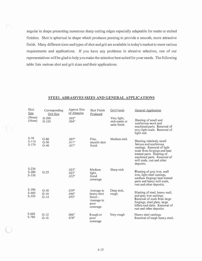
table lists various shot and grit sizes and their applications.
STEEL ABRASIVES SIZES AND GENERAL APPLICATIONS
Shot Corresponding Approx Size Shot Finish Grit Finish General Ai;112lication Size Grit Size of Abrasive Produced (None) G-200 .002" Very light,
Blasting of small and (None) G-120 .004" etch-matte or satin finish nonferrous work and
machined parts. Removal of very light scale. Removal of light rust.
S-70 G-80 .007" Fine, Medium etch S- 1 10 G-50 .0 1 [ " smooth shot Blasting relatively small S-170 G-40 .017" finish feITous and nonferrous
castings. Removal of light scale from forgings and heat treated parts. Blasting of machined parts. Removal of mill scale, rust and other deposits.
S-230 .023" Medium Sharp etch S-280 G-25 .023" light, Blasting of grey iron, mall S-330 .033" Good iron, light steel castings,
coverage medium forgings heat treated parts and heavy mill scale, rust and other deposits.
S-390 G-18 .039" Average to Deep etch, S-460 G-16 .046" heavy shot rough Blasting of steel, heavy mall, S-550 G-14 .055" finish - and gray iron castings.
Average to Removal of scale from large forgings, steel plate, large poor billets and slabs. Removal of coverage rust and other deposits.
S-660 G- 12 .066" Rough or Very rough Heavy steel castings. S-780 G- 10 .078" poor Removal of tough heavy steel.
coverage
4- 1 5

SECTION 5 - ELECTRICAL SYSTEM AND OPERATING PROCEDURES
Button/Switch Descriptions ....................................................................................... 5- 1 Operating Procedures .. ........... .......... . . ........................................................................ 5-2 Replacement Parts List .................................................... .......................................... 5-3
BUTTON/SWITCH DESCRIPTIONS
I . EMERGENCY STOP - Stops the entire system, including abrasive recycling system and
optional dust collector.
2. ABRASIVE RECLAIM START - Starts the abrasive recycling system and optional dust
collector.
3. SPINNER START - Starts the spinner drive.
4. SPINNER STOP - Stops the spinner drive.
5. BLAST WHEEL #1 START - Starts blast wheel # I .
6. BLAST WHEEL #2 START - Sta1ts blast wheel #2.
7. BLAST WHEEL STOP - Stops both blast wheels.
8. ABRASIVE ON/OFF - To blast parts set to "ABRASIVE ON". To index parts through the
blast chamber without blasting them set to "ABRASIVE OFF".
9. CHAMBER INDEX - Starts rotation of the chamber until all chambers are advanced forward
one position. The previous blast sequence must have finished.
10. CYCLE OVERRIDE - Starts rotation of the chambers forward for as long as the button is
pressed. This will interrupt a current blast sequence.
1 1 . CHAMBER ON/OFF - Allows the chamber rotation to be stopped during a cycle.
5-1 sec5/10-2 460/3672SP2BW

l
OPERATING PROCEDURES
NOTE: Operator should wear eye protection during operation of this equipment.
1. Press "Abrasive Reclaim Start" button to start the abrasive recycling system and optional
dust collector.
2. Press "Spinner Start" button to start the spinner drive.
3. Select "Chamber On".
4. Select "Abrasive On".
5. Load chamber with parts.
6. One or both of the blast wheels may be used for blasting depending on the parts and cleaning
that is desired. To stop a blast wheel, press the "Blast Wheel Stop" button and any wheels
that were left on from previous cycles will be stopped. Press the blast wheel start buttons for
those wheels to be used.
7. Set blast cycle timer to desired blast time.
8. Press "Chamber Index" button to start the blast cycle.
9. Parts may be unloaded and loaded to the next chamber when it comes to the loading station.
The chamber will rotate short distances as the blast cycle advances through the blast
positions.
10. After the blast cycle timer times out at the last blasting position the chamber will advance a
short distance then the abrasive and chamber will stop.
11. Repeat steps 7 through 10 for remaining blast cycles. Allow abrasive reclaim to run between
cycles to refill the abrasive hopper for next blast cycle.
12. Before shutting down the machine allow the abrasive reclaim and optional dust collector to
run for 1-2 minutes to refill the abrasive storage hopper.
1 3. To shut down the machine press "Emergency Stop" button.
5-2 sec5/10-2 460/3672SP2BW
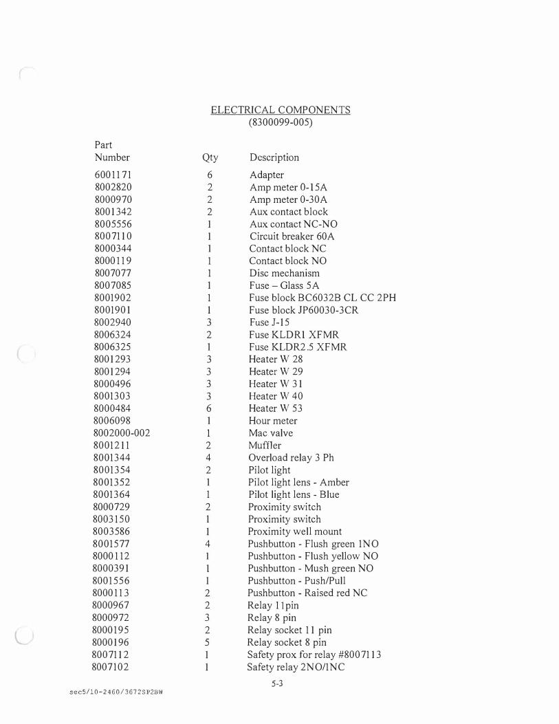
ELECTRICAL COMPONENTS (8300099-005)
Part Number Qty Description
6001 171 6 Adapter 8002820 2 Amp meter O-l 5A 8000970 2 Amp meter 0-30A 8001342 2 Aux contact block 8005556 1 Aux contact NC-NO 8007110 1 Circuit breaker 60A 8000344 1 Contact block NC 80001 19 1 Contact block NO 8007077 1 Disc mechanism 8007085 1 Fuse - Glass 5A 8001902 1 Fuse block BC6032B CL CC 2PH 8001901 1 Fuse block JP60030-3CR 8002940 3 Fuse J-15 8006324 2 Fuse KLDRl XFMR 8006325 1 Fuse KLDR2.5 XFMR 8001293 3 Heater W 28 8001294 3 Heater W 29 8000496 3 Heater W 31 8001303 3 Heater W 40 8000484 6 Heater W 53 8006098 1 Hour meter 8002000-002 1 Mac valve 8001211 2 Muffler 8001344 4 Overload relay 3 Ph 8001354 2 Pilot light 8001352 1 Pilot light lens - Amber 8001364 1 Pilot light lens - Blue 8000729 2 Proximity switch 8003150 1 Proximity switch 8003586 1 Proximity well mount 8001577 4 Pushbutton - Flush green 1 NO 8000 1 12 1 Pushbutton - Flush yellow NO 8000391 l Pushbutton - Mush green NO 8001556 1 Pushbutton - Push/Pull 80001 13 2 Pushbutton - Raised red NC 8000967 2 Relay 1 l pin 8000972 3 Relay 8 pin
L 8000195 2 Relay socket 11 pin 8000196 5 Relay socket 8 pin 8007112 1 Safety prox for relay #8007113 8007102 1 Safety relay 2NO/1NC
5-3 sec5/10-2 460/367 2SP2BW
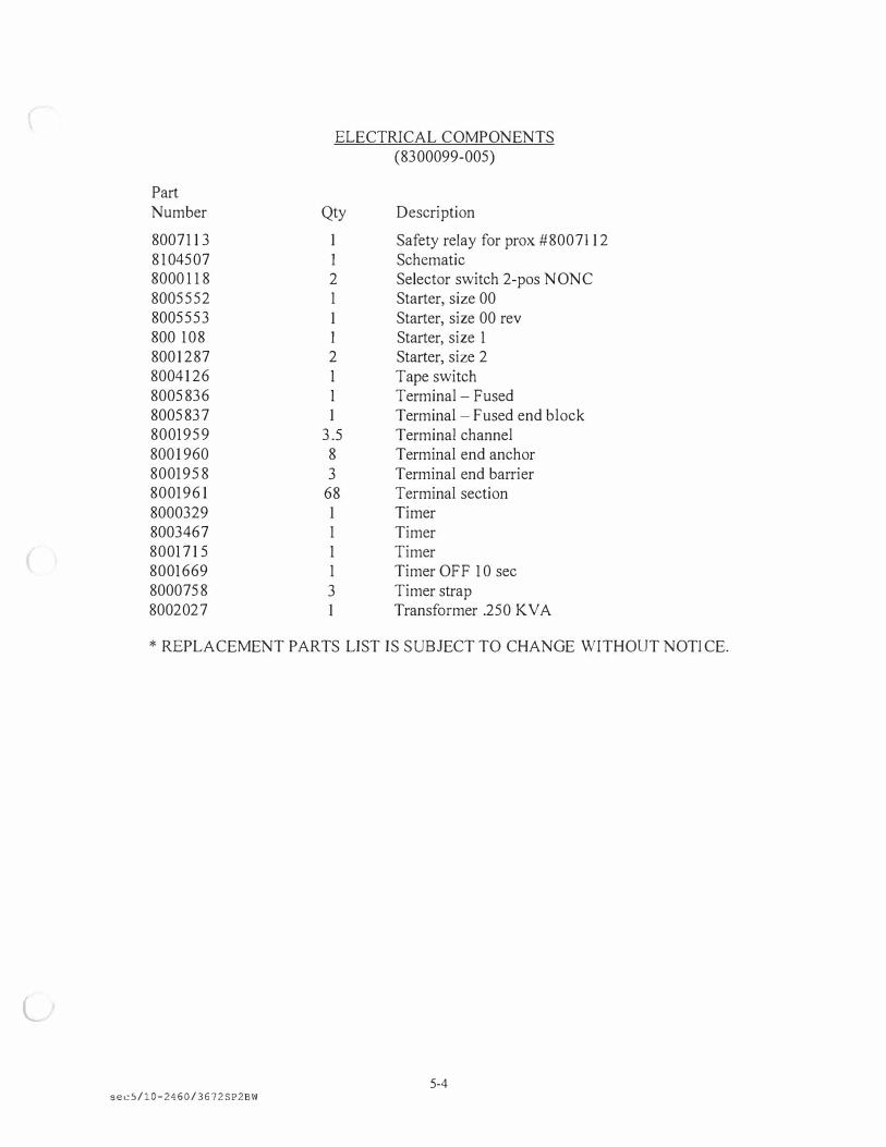
ELECTRICAL COMPONENTS (8300099-005)
Part Number Qty Description
8007113 1 Safety relay for prox #80071 12 8 104507 1 Schematic 8000 1 18 2 Selector switch 2-pos NONC 8005552 1 Starter, size 00 8005553 1 Starter, size 00 rev 800 108 1 Starter, size 1 8001287 2 Starter, size 2 8004126 1 Tape switch 8005836 1 Terminal - Fused 8005837 1 Terminal - Fused end block 8001959 3.5 Terminal channel 8001960 8 Terminal end anchor 8001958 3 Terminal end barrier 8001961 68 Terminal section 8000329 1 Timer 8003467 1 Timer 8001715 1 Timer 8001669 1 Timer OFF 10 sec 8000758 3 Timer strap 8002027 1 Transformer .250 KV A
* REPLACEMENT PARTS LIST IS SUBJECT TO CHANGE WITHOUT NOTICE.
l
5-4 sec5/10-2460/3672 SP2BW
SECTION 6 - GENERAL MAINTENANCE
Electric Motors .............................................................................................................. 6- 1 Gear Reducers ............................................................................................................... 6-3 Screen Systems ............................................................................................................. 6-3 Chambers ...................................................................................................................... 6-5 Roller Chain Drives ...................................................................................................... 6-6 Air Cylinders ...................................................... . . . ........................................................ 6-8 Pulleys, Sheaves, and HTD Sprockets .......................................................................... 6-8 Belt Drives for Spinner Hangers and Conveyors .......................................................... 6-9 Rollers ...................... . .......... . ......................................................................................... 6-1 1
l
ELECTRIC MOTOR MAINTENANCE
In the lubrication of shot blast equipment the problem of contamination is forever
present and must always be considered as a prime factor of motor bearing failure. Keep
motors free of oil, dust, dirt, water and chemicals as much as possible. On non-explosive
TEFC motors, a removable plug in the bottom center of the motor frame permits removal
of any accumulated moisture. Always keep your lubricant free from abrasive and dust.
Grease fittings and plugs and the area around them, must be thoroughly cleaned before
the pressure grease gun is applied. The grease gun itself should be kept clean and its
nozzle free from abrasive dust and grit.
Although motors are ruggedly constructed, they should be handled with care.
Dropping or jarring a motor can seriously damage its bearings. When lifting, use a
device with a capacity to handle the motor. Any motor inspections, repairs, or
replacements should be handled by qualified service or maintenance personnel.
The greatest cause of motor bearing failure is over greasing rather than under
greasing. Electric motors are basically dependable and require little maintenance. Too
much attention may be worse than none. Motor bearings are packed with grease by the
manufacturer and should operate at least one year without needing lubrication, however,
should re-lubrication become necessary the grease most commonly used by motor
manufacturers are:
Robalube Ayprina #3 BRB Lifetime Andok "C" Regal
Continental Oil Co. Shell Oil Co. Soncony Vacuum Std. Oil of New Jersey Texas Co.
Motor bearings should be lubricated using the following procedure:
1) Disconnect machine from all power sources.
2) Thoroughly clean off and remove pipe plugs from bearing housing.
3) Remove hardened grease from drains with a stiff wire or rod.
4) Add grease to inlet with hand gun until a small amount of new grease is forced
out of the drain.
5) Remove excess grease from ports and replace inlet plugs. Allow motor to drain
an adequate amount of time before replacing drain plug.
6) Motor may now be put back into full operation.
Do not lubricate the motor while in operation or excess grease could be forced into the
motor. Excess grease accumulation reduces insulation life.
6-1
Longer motor bearing life is assured by proper alignment, proper belt and chain
tension and proper lubrication. Please follow all instructions given in this manual when
attempting any replacements or repairs.
High external thrust from the driven unit is usually carried by the top bearing or
thrust bearing. If replacement of the thrust bearing becomes necessary, the new bearing
must be the same type and mounted in an identical manner. When angular contact type
bearings are replaced, the new bearing must have the same thrust capacity.
Aside from a thorough maintenance program, one of the best ways to guarantee
economical performance and long motor life is to make sure your motors operate at
nameplate voltage. In the case of a T-frame motor, applying too high a voltage will
reduce the motor ef ficiency. Too high a voltage will also lower the power factor of any
motor increasing power consumption, utility bills and core loss. Core loss shortens motor
life by overheating the insulation system.
Low voltage can also shorten motor life. When a voltage is used that is below
nameplate recommendations, the effective horsepower of the motor is reduced. If, for
example, a 5 HP motor is operated at 10% below rated voltage it becomes for all
purposes a 4 HP motor. The motor, however, will try to drive the load it was intended to
drive and become overloaded resulting in premature failure.
Operating voltages that are too high or too low can cause problems for motors of
all kinds, but operating a three-phase motor on an unbalanced or open-delta distribution
system can also cause serious overheating that will shorten motor life dramatically. A
motor operating with a 3.5% voltage unbalance, for example, will experience a
temperature rise of approximately 25%. Under normal conditions a totally enclosed
fan-cooled T-frame motor has a temperature rise of about 750C (167□F). An increase
of 25% in this case would add about 19□C (660F) to the motor operating temperature.
The rule of thumb for motor life is that for each IODC (50CF) rise in temperature above
the rated temperature, the life of the motor is reduced one half. An increase of 19 □ C
would reduce the motor life to about one fourth of normal wear.
In deciding whether to repair or replace an electric motor several factors should
be considered. Motors with unusual electrical or mechanical features are usually more
expensive and may not always be readily available. Therefore, it is frequently faster and
more economical to repair these motors.
Because of differences in frame designs, modifications may have to be made
when replacing some standard motors. In some cases an adapter may be necessary.
Depending on the motor and cause of failure, the spiraling repair costs on parts and
service could far outweigh the expense of replacement. A discussion about the motor in
6-2
l
question with a qualified electrician or your local electrical repair center can help you
determine whether repair or replacement would be most economical for you.
GEAR REDUCERS
All Goff equipment uses high quality wonn gear speed reducers. The lubricant
should be changed after the first 100 hours of operation. Drain out initial oil and flush
out the gear case with an approved non-flammable, non-toxic solvent and refill.
Thereafter, oil should be changed at least every 2500 operating hours or once a year
whichever comes first. If unit is operating in extremely dirty or high/low temperature
environments, change oil more often. A high grade, mineral base worm gear oil is
recommended for lubrication. An approved list for worm gear speed reducers is shown
below:
Texaco Texaco American Gulf Humble Shell M obil Chevron Std. of Indiana Std. of Ohio
Meropa #3 650 Cylinder Oil 196L Cylinder Oil Senate 186 Cy lesso TK-190 Valvata J82 Super Cylinder 600W Gear Comp. 240 Calumet SH Cylinder Oil Sohicyl 650
Keep shafts and vent plug clean to prevent foreign particles from entering the
seals or the gear case. Inspect periodically for oil leaks. Check couplings, set screws and
reducer mounting bolts for tightness (loose fasteners can cause alignment problems and
excessive wear). Check the end play in shafts. Noticeable movement might indicate
service or part replacement is necessary. A high grade, 1 0-W-40 motor oil is
recommended for the elevator drive torque arm reducer.
SCREEN SYSTEMS
The abrasive undergoes a screening process to remove any objects or tramp metal
that might have been mixed into it during the blasting operation. The screen system
permits the abrasive to pass but removes trash and tramp material from the system. If
trash and tramp material were to pass through the blast wheel severe damage could occur
to the blast wheels. The primary screen, located immediately under the blast chamber,
6-3
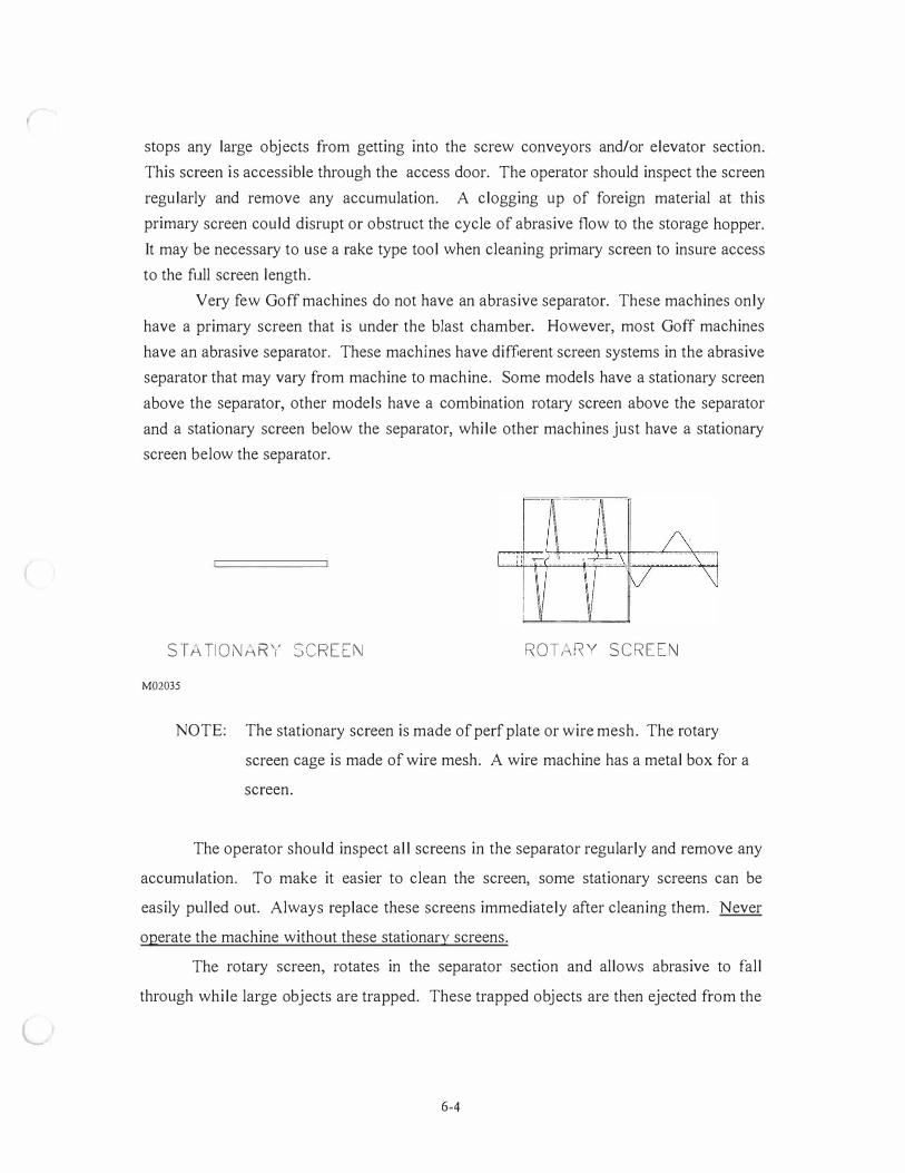
l
stops any large objects from getting into the screw conveyors and/or elevator section.
This screen is accessible through the access door. The operator should inspect the screen
regularly and remove any accumulation. A clogging up of foreign material at this
primary screen could disrupt or obstruct the cycle of abrasive flow to the storage hopper.
It may be necessary to use a rake type tool when cleaning primary screen to insure access
to the full screen length.
Very few Goff machines do not have an abrasive separator. These machines only
have a primary screen that is under the blast chamber. However, most Goff machines
have an abrasive separator. These machines have different screen systems in the abrasive
separator that may vary from machine to machine. Some models have a stationary screen
above the separator, other models have a combination rotary screen above the separator
and a stationary screen below the separator, while other machines just have a stationary
screen below the separator.
ST/-\ TI ONMRY SCREEN ROT r8Y SCREEN
M02035
NOTE: The stationary screen is made ofperf plate or wire mesh. The rotary
screen cage is made of wire mesh. A wire machine has a metal box for a
screen.
The operator should inspect all screens in the separator regularly and remove any
accumulation. To make it easier to clean the screen, some stationary screens can be
easily pulled out. Always replace these screens immediately after cleaning them. Never
operate the machine without these stationary screens.
The rotary screen, rotates in the separator section and allows abrasive to fall
through while large objects are trapped. These trapped objects are then ejected from the
6-4

system through the refuse spout. The rotary screen should be checked periodically for
accumulation and cleaned if necessary.
The long refuse spout is for discharge of trapped objects in the rotary screen. The
short refuse spout is for discharge of dirt and contaminates removed from the abrasive
during air wash separation. Both refuse spouts should be inspected periodically for
accumulation and cleaned if necessary.
CHAMBERS
There are a variety of chambers that Goff uses in its machines.
Spinner Hanger Machines have a chamber drum that is divided into 2 or 3
equal sections. The chamber drum is driven by an electric motor and reducer situated on
top of the chamber. This configuration allows the operator to unload and load one
section of the drum while the other section(s) with parts are being blasted with abrasive.
While being blasted, parts are spun in a circle in each section while resting on spinning
hanger fixtures.
Table Blast Machines have only one chamber. This chamber has a table that
spins around while the parts are being blasted with abrasive. Most tables are driven by an
electric motor and reducer situated under that table and chambers, others are driven by a
wheel that is attached to an electric motor and reducer. The wheel drives on the side of
the table while the electric and reducer operates from the outside rear of the chamber.
Barrel Blast and Tumblers have a mill belt that tumbles the parts in the
chamber. The mill belt fonns a pocket in the chamber. The ends of this pocket are
blocked off with barrel head liners as shown below.
B ;RREL HE.�D LINER
MILL BELT
M02039
6-5
L
Rod and Pipe Cleaner, Block Cleaners and Wire Mesh Machines major
function is to allow parts to enter one end of the machine and exit the other end. While
parts are in the machine, they are blasted with abrasive. These machines allow
continuous blasting of parts without stopping the machine to unload and load parts. Rod
and pipe cleaners use roller conveyors to move parts. Block cleaners and wire mesh
machines use a belt conveyor to move parts.
Liners (optional) are put into the machines to increase the life of the chamber
walls. Not every Goff machine has liners. Goff liners come in different varieties. Some
Goff machines will have more than one type of liner. These varieties include cast alloy
liners, plate liners, hanging liners, table liners, ban-el head liners, and abrasive resistant
rubber. Liner position and size were designed for ease of maintenance and replacement.
When liners get worn to half their original thickness or severe wear holes develop they
should be replaced. If liners are allowed to wear through. damage could occur to internal
chamber components.
Note: All cast alloy liners and some plate liners are fastened to the wall and/or ceiling
of the chamber with cast nuts. Barrel head liners are fastened with counter
sunk bolts to the barrel head. Abrasive resistant rubber is held in place with
bar retainers and nuts. Some abrasive resistant rubber is held in place with cast
nuts. All fasteners should be replaced when worn severely. Always check the
fasteners for wear and replacement when replacing liners. Some liners rest on
the bottom of the chamber or on top of a table. These liners do not use
fasteners.
ROLLER CHAIN DRIVES
Normal chain wear is caused by a joining of the pins in the bushings. In a
properly lubricated chain drive, separating film of fluid lubricant is formed in the
operating chain joints. Without adequate lubrication wear in the chain joints is usually
the limiting factor in the life of the chain. Such wear results in increased chain pitch.
This increase in pitch allows the chain to ride out on the sprocket teeth. When excessive
stretching occurs the chain must be replaced before it overrides the sprocket teeth.
6-6
Proper lubrication of the bearing surfaces of the chain is of major importance in retarding
wear. Installation of a new chain or badly worn sprockets will result in excessive chain
wear and serious shortening of the life of the drive.
Careful and accurate installation is essential for trouble free operation. Before
installing sprockets, the shafts should be checked to make sure that they are parallel and
level. Alignment after mounting can be checked with a string or straight-edge held
against the sides of the sprocket face. Sprockets should be located as close to the shaft
bearing as possible. Shafting and motors should be installed as rigidly as possible in
order to avoid vibration. Keyways and set screws should be checked for tightness. When
installing replacement chains, always check sprockets for excessive wear and replace if
necessary.
The life of a roller chain is usually limited by pitch elongation, or stretching, due
to wear of the load carrying joints. This finally results in failure of the chain to mesh
with the sprocket teeth.
Premature chain failure may be caused by excessive wear due to lack of
lubrication. This allows entrance of abrasive matter into the chain joints causing
corrosion. Chains must be properly lubricated for the existing conditions of load and
speed.
Chain drives should be protected against dirt and moisture and the oil supply kept
free of contamination. A fluid lubricant must be applied to assure an oil supply to the
joints and minimize metal-to-metal contact. Periodic cleaning and oil change is
recommended. A good grade of a petroleum based oil is recommended. Heavy oils and
greases are generally too stiff to enter and fill the chain joints. Below are the
recommended lubrication viscosity for various surrounding temperatures.
Temperature Degrees F
20-40 40-100 1 00- 1 20 1 20-140
Recommended Lubricant SAE 20 SAE 30 SAE 40 SAE 50
Chain life can vary depending upon the way the drive is lubricated. The better the
lubrication, the longer the chain life. At slow speeds good results are obtained by an oil
of medium consistency applied with a brush while the chain is running slowly.
6-7
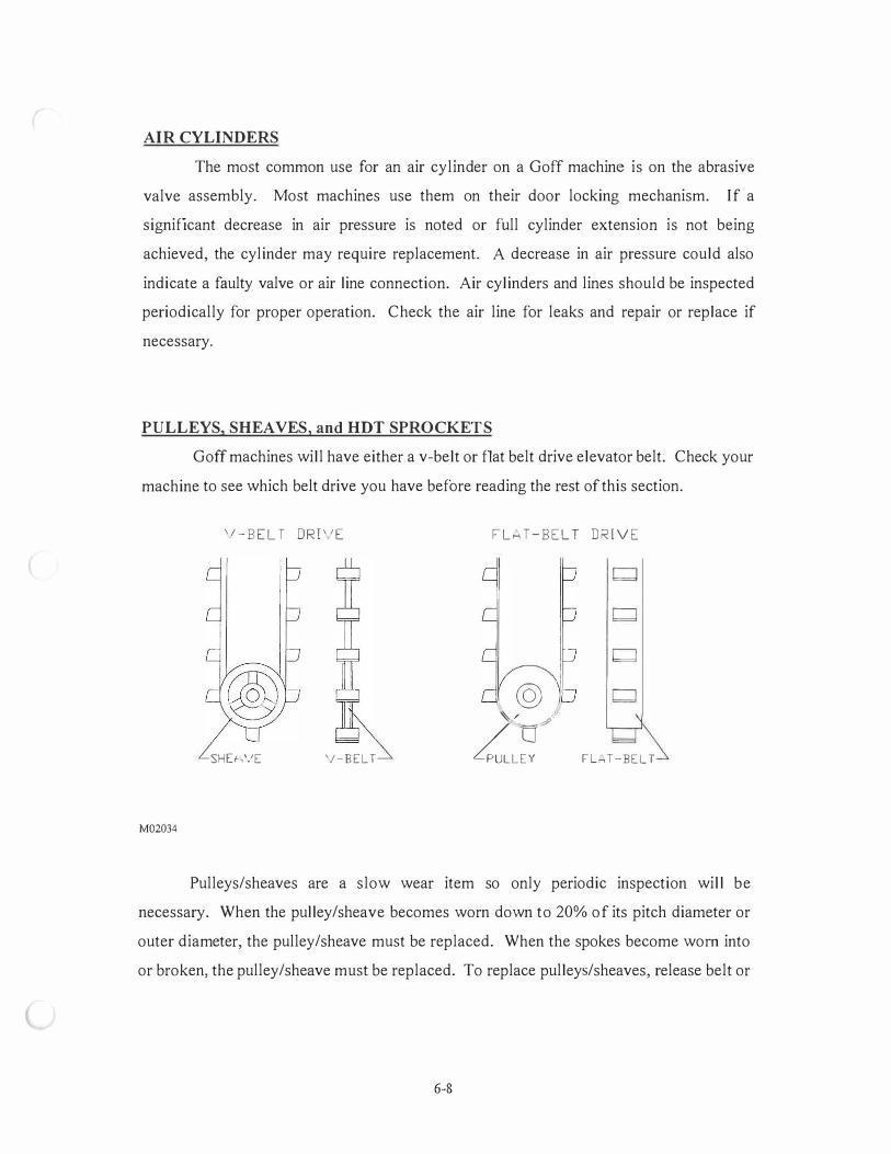
AIR CYLINDERS
The most common use for an air cylinder on a Goff machine is on the abrasive
valve assembly. Most machines use them on their door locking mechanism. If a
significant decrease in air pressure is noted or full cylinder extension is not being
achieved, the cylinder may require replacement. A decrease in air pressure could also
indicate a faulty valve or air line connection. Air cylinders and lines should be inspected
periodically for proper operation. Check the air line for leaks and repair or replace if
necessary.
PULLEYS, SHEAVES, and HOT SPROCKETS
Goff machines will have either a v-belt or flat belt drive elevator belt. Check your
machine to see which belt drive you have before reading the rest of this section.
'I - B E L T DRI ' 1 E
SHU,VE '/-BELT
M02034
F L H T - B E L T D R I V E
@ )/ /
4uLL�
v
Fln T-BELT
Pulleys/sheaves are a slow wear item so only periodic inspection will be
necessary. When the pulley/sheave becomes worn down to 20% of its pitch diameter or
outer diameter, the pulley/sheave must be replaced. When the spokes become worn into
or broken, the pulley/sheave must be replaced. To replace pulleys/sheaves, release belt or
6-8
chain tension by loosening the torque arm on the reducer, loosen set screws on shaft
bearings and slide pulley/sheave off shaft.
Spinner hangers use a variety of sheaves to drive the chamber drum and the
chamber spinner hangers. Roller conveyors use sheaves to drive rollers. They should be
periodically inspected.
Some spinner hangers use HTD sprockets and a HTD rubber belt to drive the
chamber drum. Inspect these sprockets periodically and replace if the teeth are worn,
chipped or cracked.
Always release the belt tension on any belt drive system before removing pulleys,
sheaves, or sprockets.
BELT DRIVE for SPINNER HANGERS and CONVEYORS
The proper alignment of the drive must be checked and maintained at all times. If
the drive is misaligned, the belts will rub on the sheaves/HTD sprockets causing reduced
belt and sheave/HTD sprocket life. Keep sheaves/HTD sprockets and belt free from dirt,
oil and grease. Rust nicks and burrs should be removed from the sheave/HTD sprocket
grooves and worn sheaves/HTD sprockets should be replaced. The locking devices on
the sheaves/HTD sprockets should be checked to assure and maintain proper tightness on
the shaft. Vibration or improper alignment could cause set screws, taperlock bushings or
locking caps to become loose. They should be checked and tightened periodically.
Urethane belts are orange and round. They drive the spinner hanger mechanism
above the chamber. If conveyor is roller driven then each roller is driven by a urethane
belt. Replace belts when worn or cracked. Always release the belt tension before
removing the belt.
HTD rubber belts are usually on Goff's heave spinner hanger machines. An
HTD rubber belt drives the chamber drum. Both urethane and HTD belts will be used on
heavy spinner hangers. Replace HTD rubber belts when the teeth are worn, chipped, or
cracked. Always release the belt tension before removing the belt.
6-9
l
V-belts are used on older model heavy spinner hangers. The proper installation
procedures, alignment, inspection and general maintenance of these drives are vitally
impo11ant to efficient performance of the machine.
Always use matched belts. V-belts are manufactured either by molding or are cut
to specified shape. The cross-sectional dimensions of v-belts made by various
manufacturers are not always identical, some belts may be slightly wider, some thinner or
the angle of the belt sides may be different. Make sure that all the belts on one drive are
from the same manufacturer and that they are properly matched. Never match used belts
with new ones. Belts which are improperly matched could cause a reduction in the
efficiency of the v-belt drive.
Always use matched sheaves. A sheave with an improper diameter for the belt
being used will cause a significant reduction in belt life.
When replacing v-belts it should not be necessary to pry or lever them into or out
of the sheave grooves. If excessive force is used to pry v-belt internal breakdown may
occur. To properly install or remove v-belts release pressure on the air cylinder or release
tension on the drive chain. This should allow the belt to be easily removed.
Always use a full set of v-belts. The efficiency and durability of a multiple v-belt
drive can only be assured if the drive is operated with a full set of belts as originally
designed. Operating a drive with less than a full set of v-belts results not only in loss of
efficiency but also causes an overload on the belts, shortening belt life.
Proper v-belt tension is important. If a drive is set up with the v-belts too tight, it
will force the belts to pull an unnecessary load which may cause overheating of the
bearings. If the drive is too loose, the belt may slip causing a drop in efficiency as well
as causing undue wear on the belts and sheaves. A v-belt drive is properly tightened
when a slight bow is noted on the slack side of the belt while it is running.
A void contact with oil, grease and acid. Oil and grease will cause swelling of the
v-belts and can result in premature failure. Do not be careless during lubrication. Acids
will greatly reduce belt life and hence all contact with acid should be avoided. Never use
belt dressing on a v-belt drive.
6- 10
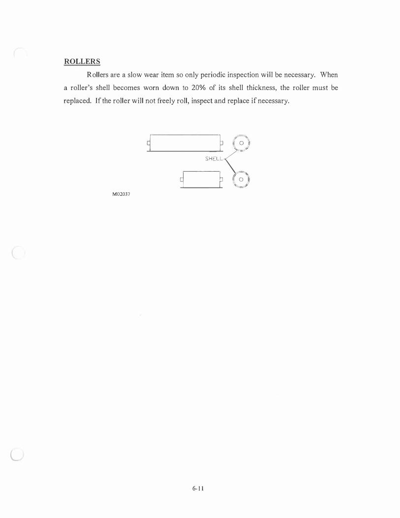
L
ROLLERS
Rollers are a slow wear item so only periodic inspection will be necessary. When
a roller's shell becomes worn down to 20% of its shell thickness, the roller must be
replaced. If the roller will not freely roll, inspect and replace if necessary.
M02037
� p � � �
.__ ______ S_
H_E�LL <�}
9�--�p � � )i
6- 1 1
SECTION 7 - SAFETY AND PREVENTIVE MAINTENANCE
Preventive Maintenance Check List ....... ............................................................................... 7-1 Suggested Preventive Maintenance ................. ...................................................................... 7-2 Safety ..................................................................................................................................... 7-6 Instructions for Welding and Cutting Work on
Descaling Machines and Blast Cleaning Systems ................................................... 7-14 Safety Tips ........................ ......... ................................................................................. . . ....... 7- 15 Lock-out/Tag-out ....................................................... . . .. . . .................................................... 7-16 Trouble Shooting
Cabinet and Blast Wheel. .............................................................. . .......................... 7-21 Abrasive Recycling System ...... .............. . . . . ................................................... .......... 7-23 Electrical System ..................................................................................................... 7-25 Dust Collection System ............................. . . . .. . ......................................................... 7-25 Hydraulic System ..................................................................................................... 7-26 Air Blast Machines .................................................................................................. 7-26 CRD Mechanics System ...................................... . . . . . ......... ............ . ......................... 7-27 WM Mechanics System ........................................................................................... 7-27

PREVENTIVE MAINTENANCE
Routine inspection is the key to preventive maintenance. This assures that needed repairs
are discovered while they are still minor. Here is a suggested maintenance check list:
PREVENTIVE MAINTENANCE CHECK LIST
AFTER 1st 10 HOURS OF
ITEM OPERATION DAILY WEEKLY MONTHLY YEARLY
Set screws - Tighten V
Blast Wheel Liners V
Blast Wheel Blades V
Blast Wheel Control Cage V
Blast Wheel Impeller V
Blast Pattern V
Fans & Motors V
Screens - Hopper V
Screens - Cabinet V
Gear/Drives/Reducers/Chain/Belts V
Check & Empty Separator Refuse V
Elevator-Sheaves-Belts-Bearings V
Electrical Components V
*Dust Collector Check & Empty V Hopper/Refuse Drum
*Table Liners-Alloy or Neoprene V
*Cabinet Liners-Cast,Alloy,or Neo. V
*Mill Tumble Belt V
*Air Dryer V
*Air Oiler V
*Belt Conveyor - Belt adjustment V
*Hydraulics V
*Nozzles V
* WHEN APPLICABLE
7-1

SUGGESTED MAINTENANCE SCHEDULE
1. Blast Wheel Wear Parts - Inspect Daily Replace when wear parts are deeply grooved or worn to half original thickness.
2. Blast Wheel - Balance & Noise - Daily Testing for balance is done by running the blast wheel with the blades in position and then without blades. A vibrating wheel indicates improper balance or possible motor failure.
3. Blast Pattern - Weekly If improperly directed the blast pattern will cause an increase in blast time as well as abnormal wear on the equipment. The blast pattern should always be checked after blade replacement or any change in abrasive being used.
4. Fans & Motors - Monthly Check for proper rotation. Improper rotation could cause a loss in power or severe damage to motor or machine. Keep motors free of oil, dust, dirt, water and chemicals as much as possible. Inspect motor bearings and lubricate when necessary. BE CAREFUL NOT TO OVER LUBRICATE. The greatest cause of motor bearing failure is over greasing not under greasing.
5. Screens - Daily A hole in the abrasive screen could allow large materials to re-circulate and reach the blast wheel causing severe damage.
6. Roller Chain and Sprockets - Inspect Monthly Maintain light film of oil - Replace when stretched beyond "take-up". Replace sprockets when teeth are worn.
7. Separator Air Flow - Daily This is done by inspecting the abrasive. If it is dirty or dusty, increase the air. Dirt and dust allowed to build up in the abrasive will use up power in the blast wheel causing a decrease in cleaning quality.
8. Elevator Belts, Buckets and Pulleys - Inspect Weekly Replace belts when worn and/or frayed or when stretched to point where belt will not "take-up" or will not track. Replace buckets when cracked or worn where 60% capacity cannot be held. Replace pulleys when lagging is worn
9. Dust Collector - Daily Inspect fan, blower, duct work, housing and filters. Improper operation of the dust collector causes a build up of dust on the working parts of the machine and causes work environment hazards. Refuse from the dust collector should be inspected daily for any traces of good usable abrasive. The dust collector should keep machine dustless but should not draw out any usable abrasives.
7-2

10. Gear Reducers - Inspect Monthly Replace gear oil every 2500 hours or annually. Check the manufactures nameplate attached to each reducer for the correct lubricant to use. Check for oil leaks. Check for end play in shafts and all bolts retaining hardware. Noticeable movement might indicate service or part replacement is necessary.
11 . Bearing - Inspect Every Six Months Bearings are lubed for life. Excess lubricant can cause abrasive contamination in the bearing and result in premature bearing failure.
12. Electric Motors - Inspect Monthly Add a small amount of oil occasionally. Excess lubricant can cause abrasive contamination in the bearing and result in premature bearing failure.
13. Hydraulics - Weekly Inspect filter and replace when necessary. Check and replace fluid annually or as conditions warrant. Keep area as clean as possible.
14. Pneumatic Components - Monthly Air cylinders and lines should be checked for proper operation and wear and leaks.
15. Cabinet and Barrel Head Liner - Inspect Daily Replace when worn to half original thickness.
16. Mill Belt - Inspect Daily Replace when worn and/ or frayed or when stretched to point where belt will not track.
17. Nozzles - Inspect Daily Since abrasive passes through the nozzle's orifice, the orifice will over time become larger. If you notice an increase in cleaning time replace the nozzle.
18. Belt Conveyor The abrasive return belt serves to transport the abrasive and sand mix to the abrasive screen conveyor.
7-3

Adjusting the belt tracking In the first operating phase of belt conveyors, care must be taken that the belt tracking is perfect even under varying operating conditions. Incorrect belt tracking will invariably cause major damage.
To adjust the tracking and the tension of the belt, tensioning spindles are provided on the tensioning station.
By tightening the right tensioning spindle (seen in the direction of the belt travel), the belt will swerve to the left.
By tightening the left tensioning spindle, the belt will swerve to the right.
If the belt tracking is perfect when the belt is unloaded, but the belt swerves to the left when loaded (seen in the direction of the belt travel), the support rollers have to be adjusted as follows:
adjust the support rollers on the left - in the direction of the belt travel.
Adjust the suppo1i rollers on the right - in the opposite direction of the belt travel.
If the belt swerves to the right proceed the same way - but reverse the procedure.
The brackets of the suppmi rollers have oblong holes.
When the belt is replaced, the belt tracking must be completely readjusted.
The support rollers and the deflection pulleys are provided with greased-for-life roller bearings.
7-4

L
Belt Conveyor Maintenance - Everyday: Check belt tracking. In the first operating phase you must check the belt once a day for straight tracking. Incorrect belt tracking increases wear and causes damage to the belt conveyor.
After every 1 60 operating hours: Check belt tracking. Check the support rollers and deflection pulleys for ease of operation. Check the wipers for wear. The wipers are equipped with adjustable rubber lips which must have full contact with the belt. Do not allow any abrasive to drop on the floor.
After every 500 operating hours: Lubricate the bearings on the drive drum and on the tensioning drum. Lubricate the tensioning spindles with dry lubricant.
After every 10,000 operating hours: Clean the bearings and change lubricant i n the geared motor according to manufacturer's specifications.
Consult your maintenance and operating manual before making any repairs to your equipment.
7-5
SAFETY
There are several advantages to an effective safety program which include: lower
operating costs, lower worker compensation, less work time lost, high employee moral and less
problems. No one can work safely without knowing what precautions one must take to ensure
one's personal safety. One must know what safety equipment to wear, which job practices are
safe and which are not, and one must be aware of what hazards are possible in one's work area.
A regular schedule of preventive maintenance on your equipment is the best protection against
unpleasant surprises that slow production and can sometimes result in injuries.
The blast cleaning system has been built in accordance with state-of-the-art standards.
Nevertheless, there can be hazards inherent in the blast cleaning system if it is used m an
improper way or for inappropriate purposes or if it is operated by non-trained personnel.
To achieve maximum operating safety, the personnel mentioned below must have
carefully read this "Safety Section" supplied by: • the plant management • the supervisors of the blast cleaning system • the operating, maintenance and repair personnel.
Make sure this manual is • kept in a place close to the blast cleaning system
■ always available a complete and in good condition
as this manual is an essential part of the protection system.
No responsibility can be assumed for damage caused by non-observance of the instruc
tions given in these manuals.
The blast cleaning system must be operated and serviced by trained operating and
maintenance personnel only. Work on the electrical system must be carried out by skilled
electricians. The fields of responsibility of the personnel must clearly be defined. This lies
within the responsibility of the plant management.
IMPORTANT Never operate the blast cleaning system without a complete and properly functioning protection system.
Therefore, it is absolute! necessa to ins ect the rotection s stem re ularl .
If, in this manual, components of the blast cleaning system are shown without protective
devices, this is only done to be more illustrative. The illustrations in this manual are schematic
diagrams.
7-6
Should any defects within the protection system occur, eliminate them immediately and report them to the supervisors or to the plant manager.
Before adjusting, servicing or repairing the blast cleaning system, you must follow the shut-off procedures explained in the Operating Instructions and put the blast cleaning system into
"lock out/tag out".
You can find an exact description of this "lock out/tag out" and how to attain it in this section.
Upon adjusting, servicing or repairing the blast cleaning system, check that all
components of the protection system are installed and operate properly.
CAUTION
Always keep a fire extinguisher on hand when perfonning cutting, grinding or welding work.
Always keep the dust collector switched off while cutting, grinding or welding within the blast cleaning system.
WARNING!
Modifications and constructional changes on the blast cleaning system without consulting us can cause impairment of the operational safety and are therefore not allowed.
A clean work environment and the observance of safety instructions and regulations help prevent accidents and increase the efficiency of the blast cleaning system.
Make sure that the safety instructions m this manual and the local accident prevention regulations are observed.
7-7

RECOGNIZE SAFETY INFORMATION
This is the safety-alert symbol.
When you see this symbol, become alert!
Your safety is involved.
UNDERSTAND SIGNAL WORDS
SAFETY
A signal word - DANGER, WARNING or CAUTION
is usually near specific hazards.
DANGER - Indicates an imminently hazardous situation
which, if not avoided, will result in death or serious
injury.
WARNING - Indicates a potentially hazardous situation
which, if not avoided, could result in death or serious
injury.
CAUTION - Indicates a potentially hazardous situation
which, if not avoided, may result in minor or moderate
injury. It may also be used to alert against unsafe
practices.
SAFETY INSTRUCTIONS - Instructions
on proper safety procedures of the
blast machine.
7-8
ILL DANGER
ILL WARNING
ILL CAUTION
SAFETY
INSTRUCTIONS
READ OPERA TING INSTRUCTIONS AND WARNING SIGNS CAREFULLY
Read all warning messages in this manual and warning signs on your machine.
Keep warning signs in good condition. Replace missing or unreadable warning signs.
LEARN MACHINE SAFETY
Carefully read this manual. Learn how to operate blast machine and how to use controls
properly.
Do not let anyone operate the blast machine without proper instruction. New operators
require special training before they begin working on the blast machine.
Unauthorized modifications to the blast machine will impair the function and/or safety
and affect machine !if e.
INSPECT MACHINE
Inspect your machine carefully each day before you start it. See Pre-Start Inspection
section in this manual.
OPERA TE MACHINE SAFELY
Persons not trained to operate or repair the blast machine should not be in the area of
operation and machine movement.
DANGER!
Only one person must use the control panel for most
operations. That one operator must walk completely around
the machine to make sure no persons are near the machine
before starting the machine. If the machine stops, determine
why it stops and when it will restart before resetting machine
and continuing the operation.
7-9
PREPARE FOR EMERGENCIES
Be prepared if a fire starts.
Keep first aid kit and fire extinguisher handy.
Keep emergency number for doctors, ambulance service, hospital, and fire department near your
telephone.
WEAR PROTECTIVE CLOTHING
Always wear fairly tight clothing and proper safety equipment.
AVOID HIGH-PRESSURE FLUIDS
Escaping fluid under pressure can penetrate the skin causing serious injury. Put blast
machine into ZMS® to relieve pressure before disconnecting hydraulic or other lines. Tighten all
connections before applying pressure. Keep hands and body away from pinholes and
connections which eject fluids under high pressure. Use a piece of cardboard to search for leaks.
If ANY fluid is injected into the skin, see a doctor immediately.
SERVICE MACHINE SAFELY
Never operate the machine if an unsafe condition exists.
Be sure you understand the service procedure before working on the machine.
Put blast machine in Zero Mechanical State (ZMS0) before doing maintenance. See
Putting Blast Machine in (ZMS®) in this manual.
DANGER!
WHEN USING TWO PEOPLE to make checks with
the machine running - the operator at the controls
must be able to see the person doing the checking.
DANGER!
DO NOT ever climb into machine when machine is not
in ZMS®
.
CLEAN THE MACHINE AND FLOOR REGULARLY
Remove any grease, oil, shot, and sand or dirt build-up to avoid possible injury or
machine damage. Remove shot beads from floor daily, or more frequently, ifrequired. 7-10
L
PROTECTION SYSTEM
Please read this operation manual before operating, testing and maintaining the protection
system.
The protection system includes this manual, guards, protective circuits, emergency stop
buttons, warning signs and machine colors. Hazardous areas are marked with warning signs.
The service access door and emergency stop protective circuits must be inspected and
tested at the beginning of each shift. DO NOT use protective circuits as control devices.
GUARDS
DANGER!
Never operate the blast machine without the
protection system operating correctly and guard in
place or severe injury may result.
DANGER!
Do not rely only on protective circuits during service
and repair. Put blast machine into Zero Mechanical
States (ZMS®
)
During operation, maintenance access panels, guard gates and guard fences must be in
place and securely closed.
Put machine in ZMS® before doing maintenance. If guards are missing, contact Disa
Goff, Inc.
PROTECTIVE CIRCUITS
The maintenance access door, located on the rear of the cabinet is equipped with an
electrical protective device.
When the operator opens this door, the protective circuit will not allow the blast machine
to start or stops the cycle of the blast machine immediately. In order to start the machine, the
maintenance access door must be closed and the operator must "report" that he is now outside the
door clearing the alarm on the panel view.
7-11
If a protective guard has an interlock that interrupts the automatic cycle, it then comes
under the definition of an "Interlocked Barrier Guard", and the operator " ... SHALL INSPECT
THE INTERLOCK AT THE BEGINNING OF EACH SHIFT OF OPERATION AND
IMMEDIATELY REPORT ANY DAMAGE OR MALFUNCTION OF THE DEVICE TO HIS
SUPERVISOR" (See ANSI Z241 .3 , para 5.2.1.4)
DANGER!
Do not rely only on protective circuits during service
and repair. Bring the blast machine into Zero
Mechanical State (ZMS®
).
7-12
l
PROTECTIVE SYSTEM COMPONENT LOCATIONS
A maintenance access door is located on the blast machine. This door must be closed to
allow machine operation. The service access door and its protective circuit must be inspected
and tested at the beginning of each shift.
ELECTRIC POWER TO CONTROL PANEL AND BLAST CLEANING MACHINE
Lock switch in the off position with padlock when it is necessary to enter machine.
MAIN AIR SUPPLY
Main air supply valve is located on the back of the cabinet. Pull valve handle to shut air
off. Lock valve in off ( closed) position when it is necessary to enter machine for maintenance or
troubleshooting.
SLACKLINE MONITOR
Monitors skip bucket hoist. If cable is slack or breaks, drum will not operate.
FLASHING LAMP
Amber light on top of control cabinet lights when machine power is turned on, when
emergency stop button is pushed or machine malfunctions.
HORN ALARM
Audible alarm that sounds, when machine starts, to alert personnel in the area.
EMERGENCY STOP BUTTONS
Pushing an emergency stop button stops all machine movements.
7-13
I.
INSTRUCTIONS FOR WELDING AND CUTTING WORK ON DESCALING MACHINES AND BLAST CLEANING SYSTEMS FOR ALUMINU M WORK PIECES
Descaling machines and blast cleaning systems for aluminum work pieces always involve
an increased risk of fire and explosion.
The plant management has the obligation to make the maintenance and service personnel aware of these dangers and to point out the hazards of fire and explosion posed by mixtures of
dust and air generated inside the blast cleaning cabin, the filters and the piping and tubing system.
Before starting any welding work, it is absolutely necessary to thoroughly dedust the
blast cleaning system. Always keep the cabinet doors open and the dust collector switched off during ongoing welding work.
Also proceed with great caution when carrying out welding or cutting work on the
exterior of the cabinet walls. Always keep fire extinguishers on hand when carrying out welding or cutting work.
7-14

L
SAFETY TIPS
1 . The first step before any maintenance or inspection takes place should be to disconnect
the power. This includes removing all electric, pneumatic and hydraulic power sources.
Then LOCK-OUT and TAG-OUT the machine.
2 . Wear proper eye protection at all times.
3 . Practice good preventive maintenance.
4. Practice good housekeeping.
5 . Replace worn parts when necessary.
6. Do not reach into elevator access while machine is in operation.
7. Do not attempt to open blast cabinet access doors until blast wheels have come to a
complete stop.
8.
9.
10 .
11.
Be sure all electrical inspections or changes are done by a qualified electrician.
Routine inspections usually require climbing onto your machine. Loose abrasive can
cause dangerous footing. Be alert and careful.
Be sure to read this operation and maintenance manual fully and carefully before
attempting any operation or repairs to this equipment.
Use a scoop or scraper when removing abrasive from a jammed elevator. DO NOT USE
YOUR HANDS! If a jammed elevator belt is stretched tight, the tension in the belt will
release when excess abrasive is removed causing the pulley to rotate rapidly in the
reverse direction. Serious personal injury could result if a hand or forearm is in the path
of the rotating buckets.
1 2. During an electrical power shortage or failure, disconnect the main power switch and
manually operate the pneumatic solenoid valve to close the abrasive flow.
1 3 . An adequate dust collection system should be used to insure a safe working environment.
1 4. After replacing parts, make sure all the tools used are removed from the machine. Be
sure all bolts and nuts are tightened. The loose connection of a rotating part could cause
the part to fly off with explosive force causing serious damage to machine and injury to
the operator.
1 5 . If the system should malfunction during cycle immediately depress the emergency stop.
7-15
L
LOCK-OUT/TAG-OUT
As described in the Safety M anual, the lock-out/tag-out is to prevent unexpected
movement of parts of the blast cleaning system and thus to provide maximal protection during
maintenance and repair work.
If protective devices are removed or work is carried out on the blast cleaning system
without protective devices, the blast cleaning system must be in lock-out/tag-out.
IMPORTANT
Although lock-out/tag-out has been established, you must still be very careful when working on the blast cleaning system.
While the blast cleaning system is in lock-out/tag-out, personal safety tags and padlocks
must be attached to the following locations:
• on the blast cleaning system personal safety tags stating that work on the blast cleaning system is in progress
• on the three-way tap of the pneumatic and hydraulic systems and the electric main switch
personal safety tags stating that these components must not be operated
• on the three-way tap of the pneumatic and hydraulic systems and the electric main switch
personal padlocks to lock these components in closed/off position
IMPORTANT
Always respect other people's safety tags and padlocks.
7-16
PUTTING THE BLAST CLEANING SYSTEM INTO LOCK-OUT/TAG-OUT
Before performing periodic maintenance work, you must unload the blast cleaning
system and stop it as described in the Operating Instructions. The cabinet door must be open and
there must not be any parts inside the blast cabinet.
To prevent inadvertent movement of individual components while the blast cleaning
system is in lock-out/tag-out, you will have to evacuate the abrasive from the blast cleaning
system.
• Position the machine to its most neutral position.
For a CRD machine, position to its zero tilt position and its drum should be its
horizontal position.
For a loader, all hydraulic and pneumatic cylinders should be in their most
compressed or relaxed states.
• Switch off the control system by pressing "Emergency Stop". o Switch off the main voltage and secure the main switch with a personal padlock to
prevent actuation by unauthorized persons. • Close the shut-off tap on the service unit of the pneumatic system and secure it with
a personal padlock. By closing the shut-off tap the pneumatic system is vented
simultaneously. Disconnect pneumatic lines at quick release connections. • Place personal warning tags on the control cabinet and on the shut-off tap of the
pneumatic system stating that maintenance work is in progress. • Close the shut-off tap on the service unit of the hydraulic system and secure it with a
personal padlock. Disconnect hydraulic lines at quick release connections. • Place personal warning tags on the control cabinet and on the shut-off tap of the
hydraulic system stating that maintenance work is in progress.
The blast cleaning system is now in lock-out/tag-out.
IMPORTANT
Before starting any maintenance work, you must put the blast cleaning system into lock-out/tagout and secure all movable parts carefully against inadvertent movement.
7- 17
l
LOCK-OUT/TAG-OUT AFTER A FAULT
If the blast cleaning system stops after a fault, there might still be parts inside the blast
cabinet. To move the parts out of the blast cabinet, proceed as described below:
• Switch off all drives. • Switch off the control system by pressing "Emergency Stop". " Switch off the main voltage and secure the main switch with a personal padlock. • Close the shut-off tap on the service unit of the pneumatic system and secure the tap
with a personal padlock. By closing the shut-off tap the pneumatic system is vented
simultaneously. Disconnect pneumatic lines at the quick release connections. • Place personal warning tags on the control cabinet and on the shut-off tap of the
pneumatic system stating that maintenance work is in progress. • Close the shut-off tap on the service unit of the hydraulic system and secure it with a
personal padlock. Disccfirnect hydraulic lines at quick release connections. • Place personal warning tags on the control cabinet and on the shut-off tap of the
hydraulic system stating that maintenance work is in progress. • Pull the door locks open by hand and open the door. • Remove all parts from the blast cleaning system
Depending on the nature of the fault, it might happen that the lock-out/tag-out cannot be
fully attained.
7- 1 8

l
TESTING THE BLAST CLEANING SYSTEM FOR L0CK-OUT/f AG-0UT
To make sure that the blast cleaning system is in lock-out/tag-out, check the following:
I . Control system - it must not be possible to switch on the control system.
2. Pressure in the pneumatic system - the pressure gauge for compressed air must indicate 0
bar, (0 psi).
3. Pressure in the hydraulic system - the pressure gauge for compressed fluid must indicate 0
bar (0 psi).
4. Cabinet door - the cabinet door must be open. It must be possible to move it by hand.
5. Bucket elevator - the buckets of the bucket elevator must be empty.
WARNING
Even when the blast cleaning system is 111 lock-out/tag-out, working on the blast cleaning system still involves certain risks.
For example, it is dangerous to remove heavy equipment components if these are not properly supported.
Any work being done on the blast cleaning system must be performed with extreme
caution.
7-19

L
RESTARTING THE BLAST CLEANING SYSTEM AFTER LOCK-OUT/TAG-OUT
After lock-out/tag-out, you must restart the blast cleaning system as follows:
1 . Check that repair or other work is completed and that nobody is within or in the
immediate vicinity of the blast cleaning system.
2 . Check that all tools which were used have been removed from the blast cleaning system.
3 . Properly reinstall all protective devices which were removed or opened.
4 . Remove the safety tag and your personal padlock from the main switch of the electric
system.
5 . Turn the main switch of the electric system to "on".
6 . Remove the safety tag and the padlock from the shut-off tap of the pneumatic system.
7 . Reconnect the pneumatic lines. Open the shut-off tap of the pneumatic system.
8 . Remove the safety tag and the padlock from the shut-off tap of the hydraulic system.
9 . Reconnect the hydraulic lines. Open the shut-off tap of the hydraulic system.
Now you can restart the blast cleaning system as described in the operating instructions.
IMPORTANT
If you see other workers' personal safety tags during the start-up procedure, stop the procedure immediately.
If necessary, re-establish lock-out/tag-out
7-20
TROUBLE SHOOTING
MALFUNCTION CAUSE SUGGESTED REMEDY
CABINET AND BLAST WHEEL
EXCESSIVE I . Unevenly worn blades I . Replace blades with a new complete VIBRATION set. Check separator adjustment.
Inadequate contaminant removal could cause blades to wear faster
2. Chipped or broken blades. 2. Usually caused by abrasive rebound action. Replace blades with complete new set. If frequent chipping or breakage is noted, your abrasive mixture may be too large for your needs. A smaller size mixture could be more economical and just as effective.
3. Improperly mounted blast 3. Blast wheel unit should not wobble or wheel. vibrate excessively. Unit should be
tightened down even!) . If blast wheel unit develops severe leakage or wear holes in housing, unit may need replacement.
EXCESSIVE NOISE I . Improper clearance 1. Check alignment and mounting of between the rotating parts. rotating parts. Patis should not be
allowed to knock against each other during rotation.
2. Abrasive size. 2. Be sure to use the abrasive mixture that best meets your needs, provides good blast coverage, quieter operation, and more efficient cleaning or shot peening.
3. Loose bolts or set screws 3. Check base plates, motor bearings, housings and sheaves. Make certain all components are firmly secured. Check belt tension.
4. Defective bearing. 4. Check all bearings (motor & drive), a smooth free rotation should exist. Replace worn or defective bearings. Lubricate motor bearings if necessary. DO NOT OVER LUBRICATE
INCREASED I . Improper abrasive feed to I . If ammeter indicates a lower ampere CLEANING TIME blast wheel. reading than the normal full load
rating: - reduces efficiency a. Check storage hopper and add of equipment
abrasive if level is low.
7-2 1
l
MALFUNCTION - denotes a malfunction which even though it permits production to continue it might eventually cause serious machine damage
ABRASIVE LEAKAGE
TROUBLE SHOOTING
CAUSE SUGGESTED REMEDY
2. Loss of direction control of 2. the blast pattern. This will cause abrasive to strike sections of the blast chamber rather than the work to be blasted, increasing cleaning time, wear and maintenance.
b. Check abrasive for dirt or other contaminants which should have been removed by the separator.
c. Check separator adjustment.
d. Check feed lines for obstructions that could reduce flow through the feed spout or abrasive valve. Clean or blow out if necessary
e. Check impeller for wear. Replace if necessary.
f. Check motor and blast wheel rotation for proper operation.
g. Make sure wheel is not overloaded with more abrasive than it can handle. Check and adjust the abrasive valve accordingly.
h. Check screens for any accumulation of objects or debris that could disrupt the cycle of abrasive flow.
Conduct an accurate blast pattern test. Check the "hot spot" location and adjust control cage accordingly. The "hot spot" should be directed onto the work to be blasted at the most beneficial angle. Inspect control cage and impeller for wear. Replace if necessary.
1. Improper sealing. 1. Maintain and replace all worn seals in the blast wheel housing and feed spout. Check chamber seals and replace if necessary.
2. Worn liners.
7-22
2. Inspect liners on a daily basis and replace when necessary. If liners are allowed to become too worn abrasive wear or damage could occur to the blast wheel housing, blast chamber or blast doors allowing abrasive to leak out.

TROUBLE SHOOTING
MALFUNCTION CAUSE SUGGESTED REMEDY INSUFFICIENT AIR 1. Faulty air cylinder 1. Check and replace air cylinder if PRESSURE necessary.
2. Faulty valve. 2. Check and repair or replace.
3. Faulty air lines 3. Air hoses could become clogged causing air flow to be obstructed. Blow hoses and clean lines. Check for any leaks. Repair or replace if necessary.
VARIABLE 1 . Worn or loose belt 1. Check belts for wear and tension. EXPOSURE TIME Replace if necessary. AND MA TERI AL
2. Worn sheave 2. Check sheaves and replace if FINISH necessary.
3. Worn bearings. 3. Check bearings for wear and replace if necessary.
4. Faulty air cylinder 4. Check air cylinder for proper operation and pressure. Replace or repair if necessary.
ABRASIVE RECYCLING SYSTEM
STALLED 1. Clogged screens 1. Clean screens regularly. When screens ELEVATOR become clogged abrasive backs up into
the elevator causing a jammed condition. Inspect and replace screens when worn.
2. Worn elevator buckets. 2. If buckets are worn they will no longer carry their pre-determined load. Replace buckets when necessary. If belts show considerable wear replace complete assembly.
3. Storage hopper overflows. ,., .) . If too much abrasive has been added to
the system or an accumulation of dust and contaminants has been delivered to the storage hopper it will fill above capacity level causing abrasive material to back up and jam. Drain off excessive abrasive and check abrasive for excessive dust and dirt accumulation. If dust and dirt are present check separator for proper operations and
l adjustment. Storage hopper should be maintained at 3/4 full.
4. Abrasive added too fast. 4. When making abrasive additions, especially when machine is in
7-23
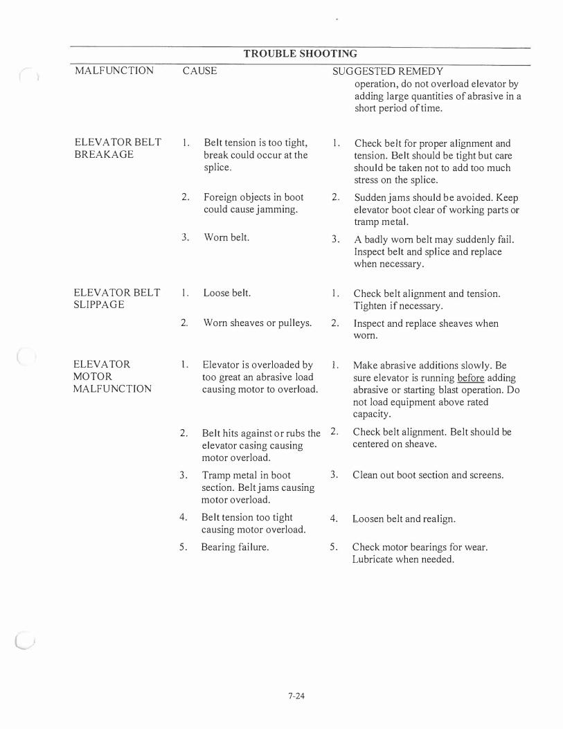
TROUBLE SHOOTING
MALFUNCTION CAUSE SUGGESTED REMEDY operation, do not overload elevator by adding large quantities of abrasive in a short period of time.
ELEVATOR BELT I . Belt tension is too tight, I . Check belt for proper alignment and BREAKAGE break could occur at the tension. Belt should be tight but care
splice. should be taken not to add too much stress on the splice.
2. Foreign objects in boot 2. Sudden jams should be avoided. Keep could cause jamming. elevator boot clear of working parts or
tramp metal.
3. Worn belt. 3 . A badly worn belt may suddenly fail. Inspect belt and splice and replace when necessary.
ELEVA TOR BELT I . Loose belt. I . Check belt alignment and tension. SLIPPAGE Tighten if necessary.
2. Worn sheaves or pulleys. 2. Inspect and replace sheaves when worn.
ELEVATOR I . Elevator is overloaded by I . Make abrasive additions slowly. Be MOTOR too great an abrasive load sure elevator is running before adding MALFUNCTION causing motor to overload. abrasive or starting blast operation. Do
not load equipment above rated capacity.
2. Belt hits against or rubs the 2. Check belt alignment. Belt should be elevator casing causing centered on sheave. motor overload.
3 . Tramp metal in boot 3 . Clean out boot section and screens. section. Belt jams causing motor overload.
4. Belt tension too tight 4. Loosen belt and realign. causing motor overload.
5. Bearing failure. 5. Check motor bearings for wear. Lubricate when needed.
l
7-24
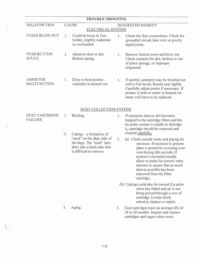
l
MALFUNCTION
FUSES BLOW OUT
PUSH BUTTON STUCK
AMMETER MALFUNCTION
DUST CARTRIDGE FAILURE
TROUBLE SHOOTING
CAUSE SUGGESTED REMEDY ELECTRICAL SYSTEM
I . Could be loose in fuse holder, slightly undersize or overloaded.
I . Abrasive dust or dirt. Broken spring.
1. Dirty or bent pointer. Ammeter is burned out.
I . Check the fuse connections. Check for grounded circuit, bare wire or poorly taped joints.
I . Remove button cover and blow out. Check contacts for dirt, broken or out of place springs, or improper alignment.
1 . If careful, ammeter may be brushed out with a fine brush. Reseal case tightly. Carefully adjust points if necessary. If pointer is bent or meter is burned out meter will have to be replaced.
DUST COLLECTION SYSTEM
1. Binding 1 . If excessive dust or dirt becomes trapped in the cartridge fibers and the air pulse system is unable to dislodge it, cartridge should be removed and
2. Caking - a formation of cleaned carefully.
"mud" on the dirty side of 2. (a) Check outside vents and piping for the bags. The "mud" later moisture. If moisture is present dries into a hard cake that place a protective covering over is difficult to remove. vent during idle periods. If
system is mounted outside allow to pulse for several extra minutes to assure that as much dust as possible has been removed from the filter ca1iridge.
(b) Caking could also be caused if a pulse valve has failed and air is not being pulsed through a row of cartridge. Locate faulty valve(s), replace or repair.
3. Aging. 3. Dust cartridges have an average life of 18 to 36 months. Inspect and replace cartridges and cages when worn.
7-25
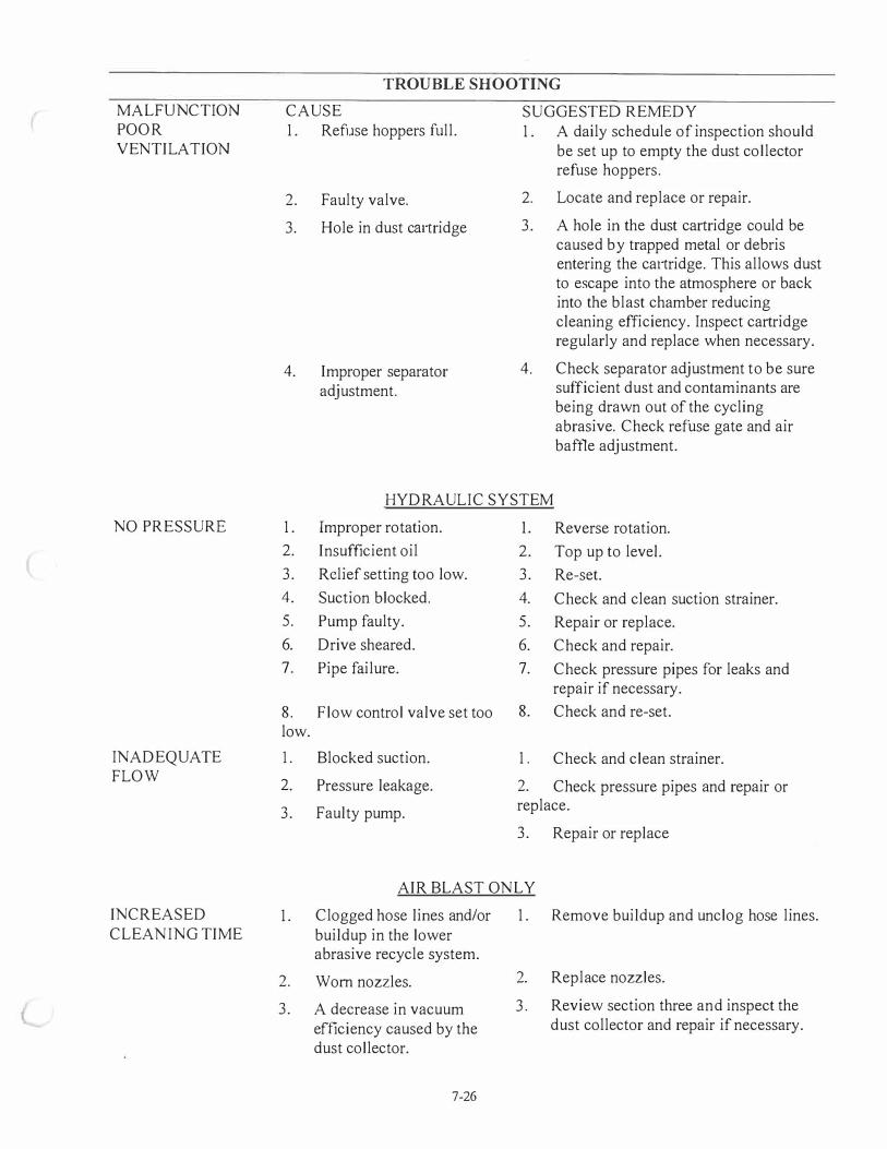
MALFUNCTION POOR VENTILATION
NO PRESSURE
INADEQUATE FLOW
INCREASED CLEANING TIME
TROUBLE SHOOTING
CAUSE 1. Refuse hoppers full.
2. Faulty valve.
3. Hole in dust cmiridge
4. Improper separator adjustment.
SUGGESTED REMEDY 1. A daily schedule of inspection should
be set up to empty the dust collector refuse hoppers.
2. Locate and replace or repair.
3. A hole in the dust cartridge could be caused by trapped metal or debris entering the ca1iridge. This allows dust to escape into the atmosphere or back into the blast chamber reducing cleaning efficiency. Inspect cartridge regularly and replace when necessary.
4. Check separator adjustment to be sure sufficient dust and contaminants are being drawn out of the cycling abrasive. Check refuse gate and air baffle adjustment.
HYDRAULIC SYSTEM
1. Improper rotation. 1. Reverse rotation. 2. Insufficient oil 2. Top up to level. 3. Relief setting too low. 3. Re-set. 4. Suction blocked. 4. Check and clean suction strainer. 5. Pump faulty. 5. Repair or replace. 6. Drive sheared. 6. Check and repair. 7. Pipe failure. 7. Check pressure pipes for leaks and
repair if necessary. 8. Flow control valve set too 8. Check and re-set. low.
1. Blocked suction. 1. Check and clean strainer.
2. Pressure leakage. 2. Check pressure pipes and repair or
3. Faulty pump. replace.
3. Repair or replace
AIR BLAST ONLY
1. Clogged hose lines and/or 1. Remove buildup and unclog hose lines. buildup in the lower abrasive recycle system.
2. Worn nozzles.
3. A decrease in vacuum efficiency caused by the dust collector.
7-26
2. Replace nozzles.
3. Review section three and inspect the dust collector and repair if necessary.

{
(
MALFUNCTION
PARTS CAUGHT BETWEEN BELT AND DRUM
EXTREME HYDRAULIC PRESSURE
PARTS NOT EXITING DRUM ONTO VIBRATORY CONVEYOR
BELT MALFUNCTIONING
TROUBLE SHOOTING
CAUSE SUGGESTED REMEDY CRD MECHANIC SYSTEM
1 . Belt loose.
2. Parts caught between belt and drum.
I .
2.
CRD tilt position is zero.
Parts too big.
3 . Fast feed rate of parts into drum.
4. Drum is not oscillating properly.
1 . Review section six - tightening belt
2. Inspect drum and belt for loose parts. If parts are caught between belt and drum, remove parts and tighten belt (see section six).
EXCESSIVE OF 850psi FOR ALUMINUM PARTS OR I O00psi FOR CAST IRON AND STEEL PARTS
I .
2.
Increase tilt position above zero.
Use smaller parts. Contact Goff for possible larger machine.
3 . Lower the feed rate of parts into drum.
4. (a) Review section six and make sure everything is in its proper position.
(b) Check the hydraulic system. Make sure all hoses, valves, and fittings are not leaking. Make sure the torque hub, torque drive, and hydraulic pump are functioning properly and replace any components if needed.
(c) Make sure the C3 coupling and bearing on the drive shaft are functioning properly and replace if needed. Make sure the C3 coupling is correctly aligned.
WM MECHANIC SYSTEM
1. Belt off track. I . Review section three - belt installation and adjustment.
2. Belt stretching. 2. Review section three - belt installation and adjustment.
3. Belt breaking. 3. Repair and replace if necessary.
4. Belt curling. 4. Review section three - belt installation and adjustment.
7-27