golf car troubleshooting guideacgcars.us/support/2009_troubleshooting_guide.pdfgolf car...
TRANSCRIPT

Golf Car Troubleshooting Guide 08-09 Alltrax/Wolf Controller
Problem: Car not running Steps to diagnose car
1. Turn key to on position
2. Check if indicator lights are on
3. Turn forward-reverse switch to neutral, then reverse, then back to forward

4. Check if horn works
5. Check if turn signals work
6. Check if the headlights work
7. Check if brake lights work
8. Turn key to on position
9. Check the red wire opposite the on/off solenoid. This should read 45 to 52 volts
10. Set volt meter to 200 volts DC

11. Attach negative lead to B negative (B-) on speed control
12. Touch front terminal to on/off solenoid. Voltage should read 45 to 52 volts
13. Move hot lead to forward-reverse solenoid on blue wire. Should read 45 to 52 volts

14. Check motor
15. Set volt meter to diode meter
16. Disconnect s1 wire for motor
17. Check continuity of 4 motor terminals, s1 – s2 should have continuity.

18. A1 and A2 should have continuity
19. Set volt meter to 200 volts DC
20. With the negative lead still on B negative, check the brown cable on the speed controller box, it should
read 48 volts
21. Set volt meter to 200 k ohms

22. Take the red lead of volt meter and touch the orange wire and with the black lead touch the green
wire, these are the potentiometer wires
23. The potentiometer with full throttle should read 4.7 to 5.0 k ohms. The car should be driven or raised on
jack stands to do this test
Problem: Key switch is not working
1. Set volt meter to 200 volts DC
2. Take the negative lead of volt meter and place on black wire of cigarette lighter

3. With the positive lead of volt meter check the voltage on both terminals of the switch and key switch must be on. Should read 48 volts
Problem: Headlights, taillights, horn doesn’t work (voltage converter doesn’t work)
1. Set volt meter to 200 volts DC
2. Check 40 amp fuse for voltage converter
Note: Roadster has an extra fuse in the wiring harness next to voltage converter
3. Locate the connector for voltage converter and place the negative lead of the volt meter on the
black wire of the connector with the red lead touching the brown wire. It should have 48 volts

4. With the negative lead still on the black wire, touch the pink wire with the red lead and it should have 12
volts
Problem: F/R Solenoid doesn’t work
1. Set volt meter on 200 volts DC
2. Turn on key switch (make sure dashboard is on)
3. Set F/R switch on forward
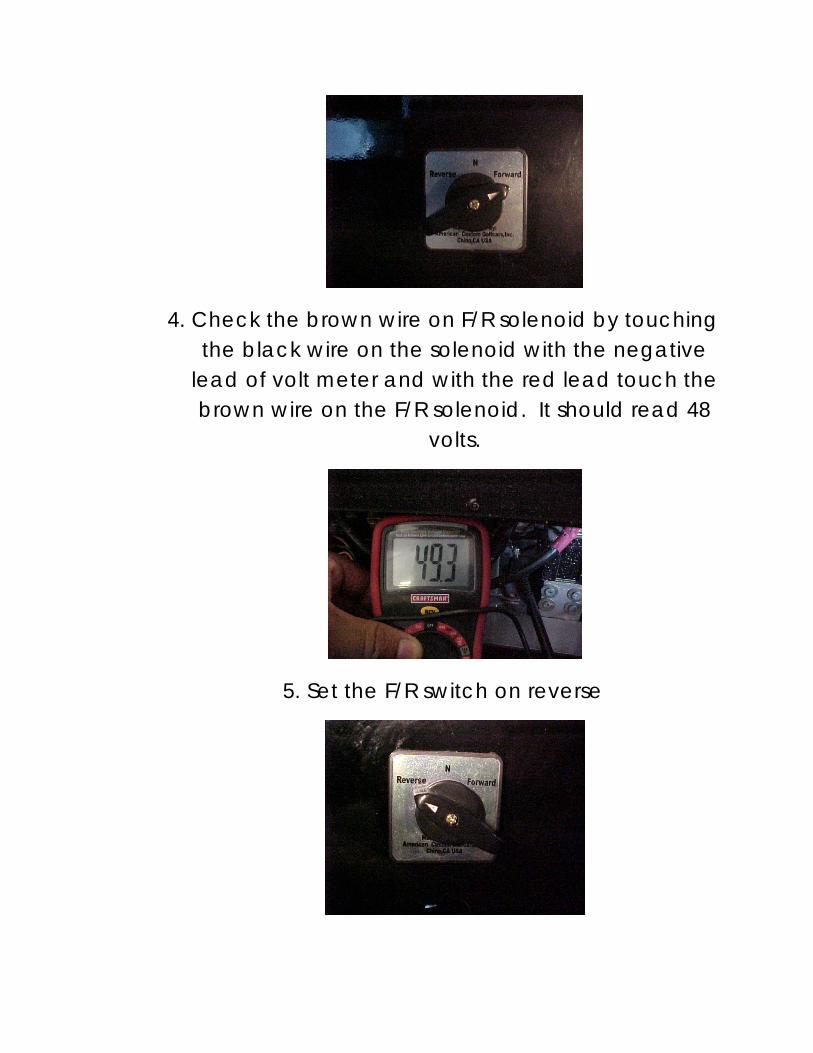
4. Check the brown wire on F/R solenoid by touching the black wire on the solenoid with the negative
lead of volt meter and with the red lead touch the brown wire on the F/R solenoid. It should read 48
volts.
5. Set the F/R switch on reverse

6. Check the voltage on the green wire of the F/R solenoid by touching the negative lead with the black wire and the red lead touching the green
wire
7. With the keys witch still on and the F/R on neutral: Take the black lead of the volt meter and touch the B negative (B-) on speed controller, with the
red lead touch the yellow (A2) and then touch the white (A1) wire, it should read plus or minus 0.0
volts
8. Now with the F/R switch on forward, the voltage should read 48 volts on the 4 terminal of the F/R
solenoid

Problem: F/R switch doesn’t work
1. Set the volt meter on diode meter
2. Disconnect the F/R switch

3. Take the red lead of volt meter and touch the grey wire with the black lead touch the brown wire then turn the F/R switch to forward, it should have continuity. To check the switch on reverse do the same, only change the switch on reverse and with the red lead touch the green wire, it should have continuity
4. Plug in the F/R switch that you just disconnected and turn on the key switch
5. Set volt meter to 200 volts DC
6. Place the negative lead of volt meter on the negative side of batteries and with the positive lead touch the grey wire, it should have 48 volts

7. With the black lead still on the negative of battery pack turn the F/R switch on forward and touch with the red lead, the brown wire of F/R switch should read 48 volts
8. Turn the F/R switch on reverse, touch with the red lead of volt meter, the green wire on the F/R switch, the voltage should read 48 volts

Problem: On/off solenoid doesn’t work
1. Check on the fuse box the ignition fuse (5 amp)
2. Set volt meter to 200 volts DC
3. Turn key switch on
4. The solenoid has two wires attached, take the negative lead of volt meter to the black wire and with the red lead touch the grey wire. Voltage should read 48 volts

5. Set the negative lead of volt meter on B negative (B-) of speed controller
6. With the red lead of volt meter touch both top terminals of on/off solenoid (one at a time) the voltage should read 48 volts on both

How to check the ceramic resistor and diode for On/off solenoid:
1. Take diode off of solenoid
2. Set volt meter to diode meter
3. Take red lead of volt meter and touch the side of ceramic resistor and with the black lead touch the side of the diode (as seen in picture). The reading should be around 750 ohms

4. Put diode back on solenoid
Problem: Potentiometer doesn’t work
1. Set volt meter at 200 K ohms
2. Take off plastic covers from the potentiometer

3. Disconnect cable from potentiometer, take off the red lock off the plug, take a set of
alligator cables and grab the terminals and then connect the leads to the volt meter. It
should read 0 ohms without pressing the
accelerator
4. When your press on the accelerator all the way down, it should read 5.0 k ohms

5. To calibrate the potentiometer move the adjustment bolt for the potentiometer
plastic arm all the way forward
6. Now we have to move the adjustment bolt for the throttle pedal all the way to the top

7. Last step is to calibrate the potentiometer from 0.0 k ohms to 5.0 k ohms by moving the set screw on the potentiometer
Note: when vehicle is stopped, the potentiometer should always read 0 k ohms