good practices in radiation exposure dose reduction measures
TRANSCRIPT

Commissioned by the Ministry of Health, Labour and Welfare in FY2017Project to Enhance the International Transmission of Radioactivity-Related Information
on the Workers at TEPCO Holdings’ Fukushima Daiichi Nuclear Power Plant
Edited: Japan Environment Research Co., Ltd.
Pedestal
1F-Unit 3 reactor
Underwater ROV
“Unit 3 Reactor: How to Reduce Exposure Dose during Internal Investigation of Reactor Containment Vessel, and Removal and Installation of Fixed Thermometer” (Material provided by Toshiba Energy Systems & Solutions Corporation)This includes results achieved by the International Research Institute for Nuclear Decommissioning and Toshiba Energy Systems & Solutions Corporation with a FY2015 subsidy for decommissioning and contaminated water management (for developing techniques for investigating the inside of reactor containment vessek).
Lifting thruster Propulsion thruster
Front camera
Lighting
Cable
Good Practices in Radiation Exposure Dose Reduction Measures

Beforeimplementation
Afterimplementation
Reductionamount
29-01-01 RB 3 Shielding the front of X-6 of Unit 2 reactor building -- -- --
29-01-02 RB 3 Shielding the front of X-6 of Unit 2 reactor building -- -- --Shielded so the air dose rate becomes1/1000 of the original value.
29-02-01 RB 5 Adopting the remote monitoring system 1.0 0.87 -- Relative value
29-02-02 RB 5 Adopting the remote monitoring system 1.0 0.87 -- Relative value
29-02-03 RB 5 Configuring the remote monitoring system -- -- 119
29-03 RB 6Preventing contamination of insertion apparatus whenpulling it out of the PCV
-- -- 77
29-04-01 TB 2Changing the work place to an area with a low radiationexposure dose rate
7 to 22 0.5 to 4.0 --
29-04-02 TB 5Changing the work place to an area with a low radiationexposure dose rate
7 to 22 0.5 to 4.0 --
29-05-01 TB 3 Shielding heater drain piping and other parts 5.6 1.6 --
29-05-02 TB 3 Shielding heater drain piping and other parts -- -- --
29-06 TB 3Shielding the accessible area of the upper part of thecondenser
-- -- --
29-07 TB 3Shielding the transfer lines of water stored in thecondenser
-- -- --
29-08 TB 3 Shielding the opening around the condenser 2.4 1.4 --
29-09-01 TB 3 Installing pre-assembled partitioning shields 2.8 0.11 --
29-09-02 TB 3 Installing pre-assembled partitioning shields 2.8 0.11 --
29-10-01 TB 5 Removing accumulated sludge -- -- --
29-10-02 TB 4 Removing accumulated sludge -- -- --
29-11 TB 4Diluting the water with a high radiation exposure dose ratethat was stored in the condenser
-- -- --Diluted until the amount of radioactive substancesinside the condenser becomes 1/30 of the originalvalue.
29-12 TB 7 Setting and indicating the access route -- -- --
29-13 R 2Setting lifting facilities in areas with a low radiationexposure dose rate
-- -- --
29-14 R 2Setting traffic lines and waiting areas at places with lowradiation exposure doses
1.0 0.46 -- Relative value
29-15 R 3 Shielding the periphery of Unit 3 reactor building 1.0 0.30 (228) Relative value
29-16 R 3Shielding for radioactive substances from the upper part ofUnit 3 turbine building
-- -- --
29-17 R 3 Shielding for beta rays inside the flange tank 89.4 2.4 --
29-18 R 3 Adopting shielding trolleys 1.0 0.46 -- Relative value
29-19-01 R 4 Removing rubble before applying waterproof coating -- -- --
29-19-02 R 4 Removing rubble before applying waterproof coating -- -- --
29-20 R 5Using a remote sprayer to control spreading of thecontamination on the inner surface of the tank
42.3 pertank
0 per tank42.3 per
tank
29-21 R 6Contamination management during flange tankdisassembly
-- -- --
29-22 R 7Reducing workload by developing and using the superfluidconcrete material
1.0 0.25 -- Relative value
29-23 R 7 Mechanizing waterproof coating 1.0 0.46 -- Relative value
Note: The above good practices have been taken from the Radiation Exposure Dose Reduction Measures Workshop held on November 9, 2017, and then edited.
Contents List of Good Practices in Radiation Exposure Dose Reduction Measures
No. Location Category Title
Radiation exposure doseequivalent (mSv) Notes

1F Site Operation Zone Control(1) 1F site operation zone status
(2) 1F site area map
Zone Protective Equipment
Red zone (Anorak areas)- Inside Units 1 to 3 reactor buildings- Area with stored water around Units 1 to 4 reactor buildings
- Full-face mask- 2 layer coveralls or anorak- Work boots (for R zone)- Helmet (for R zone)- Cotton gloves + rubber gloves
Yellowzone(Coverallsareas)
- Inside buildings that include water treatment facilities (such as desalinization units, multi-nuclide removal facilities)*1- Work in areas around tanks that contain concentrated salt water, strontium-treated water*2, and work that involves the handling of transport lines to tanks
- Full-face mask- Coveralls- Work boots (for Y zone)- Helmet (for Y zone)- Cotton gloves + rubber gloves
- Around Units 1 to 4 buildings- Specified as required to suit work environment (such as inside Units 5, 6 buildings, parts of storage areas for high-radiation exposure dose rubble)
- Half-face mask- Coveralls- Work boots (for Y zone)- Helmet (for Y zone)- Cotton gloves + rubber gloves
Green zone (Regular uniform areas)Areas except the above. Y areas of the following have been changed to G from March 30,2017: some parts of the periphery of Units 1 to 4 buildings and their slopes.
- D2 mask- Site clothing, regular work clothing*3- Work boots (for G zone)- Helmet (for G zone)- Cotton gloves + rubber gloves or work gloves
- Inside important anti-seismic buildings and inside rest areas
*1: Excludes observations and other operations that are not considered work.*2: Excluding work that does not involve the handling of concentrated salt water, patrolling, field surveys in the work planning phase, observation visits, etc.*3: Certain light work (such as patrolling, monitoring and transportation of items brought in from outside the premises).
Source: Japan Space Imaging Corporation, ©DigitalGlobe
As of Feb. 5, 2018. Material provided by Tokyo Electric Power Company Holdings, Incorporated.
R zone [Anorak area]*1
Y zone [Coverall area]*2
G zone [Regular work clothing area]*3
Continuous dust monitor
Unit 1 seaside Unit 3 seaside
Former entry and exit control point for units 5 and 6
Former health and welfare
Former information
Main anti-seismic building
Slopes for units 1 and 2
Slopes for units 3 and 4
H tank area
Shield main control room
South side of HTI South side of
Unit 3
Registration center
Main entrance security
*1: Inside Units 1 to 3 reactor buildings, and areas with stored water around Units 1 to 4 turbine buildings and surrounding buildings *2: The Y zone shown in dotted yellow lines is for when working with concentrated salt water or work related to contamination, and requires G zone equipment during patrols or when
conducting site surveys for creating work plans. When performing work under high dust concentration (such as demolishing buildings) in the G zone, or working with concentrated saltwater or work related to tank transfer lines, those areas will be temporarily specified as the Y zone.
*3: In addition to the G zone in the map, this also applies to some areas of the common pool building 2F and 3F.
Inside reactor building RB 1 TimeInside turbine building TB 2 DistanceR ZONE R 3 ShieldingY ZONE Y 4 Removing radiation source
G ZONE G 5 Remote-control, robot operation
Other ( 6 Preventing spread of contamination
) 7 Other
Location Category Good Practices in RadiationExposure Dose Reduction
MeasuresRB 3Z No. 29-01-01
Title Shielding the front of X-6 of Unit 2 reactor building
Work location The front of the 1F X-6 of Unit 2 reactor building
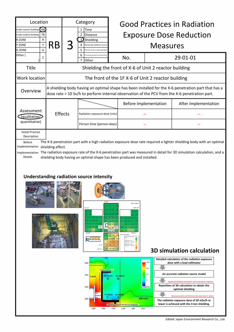
Overview A shielding body having an optimal shape has been installed for the X-6 penetration part that has adose rate > 10 Sv/h to perform internal observation of the PCV from the X-6 penetration part.
Assessment Effects
Before Implementation After Implementation
Radiation exposure dose (mSv) -- --(qualitative/quantitative) Person time (person-days)
Edited: Japan Environment Research Co., Ltd.
-- --
Good PracticeDescription
BeforeImplementation
The X-6 penetration part with a high radiation exposure dose rate required a lighter shielding body with an optimalshielding effect.
ImplementationDetails
The radiation exposure rate of the X-6 penetration part was measured in detail for 3D simulation calculation, and ashielding body having an optimal shape has been produced and installed.
19 mSv/h②
19 mSv/h④
6 mSv/h③
9 mSv/h① 100 Sv/h
1 Sv/h
(mSv/h)
Ceiling shielding ↓
↑ Shielding bodies for the floor are integrated.
Exte
nsio
n of
a s
hiel
ding
bod
y↓
X-6 penetration
Detailed calculation of the radiation exposure dose with a lead collimator
An accurate radiation source model
Repetition of 3D calculation to obtain the optimal shielding
The radiation exposure dose of 20 mSv/h or lower is achieved with the 3-ton shielding.
Quality of shielding calculation and assessment improves.
Necessary parts and thickness become clear in detail.
Understanding radiation source intensity
3D simulation calculation
Shield thickness60 mm
Shield thickness62 mm
Left wall
Unit: mSv/h
Right wall
Ceiling
Buried steel plateMeasurement from the front
Measurement at an angle of 45° diagonally
Measurement at an angle of 75° diagonally
Floor face
Groove Groove
Groove
Min.
Max.

Inside reactor building RB 1 TimeInside turbine building TB 2 DistanceR ZONE R 3 ShieldingY ZONE Y 4 Removing radiation source
G ZONE G 5 Remote-control, robot operation
Other ( 6 Preventing spread of contamination
) 7 Other
Location Category Good Practices in RadiationExposure Dose Reduction
MeasuresRB 3Z No. 29-01-02
Title Shielding the front of X-6 of Unit 2 reactor building
Work location The front of the 1F X-6 of Unit 2 reactor building
Overview A shielding body having an optimal shape has been installed for the X-6 penetration part that has adose rate > 10 Sv/h to perform internal observation of the PCV from the X-6 penetration part.
Assessment Effects
Before Implementation After Implementation
Radiation exposure dose (mSv) -- --(qualitative/quantitative)
Person time (person-days)
Edited: Japan Environment Research Co., Ltd.
-- --
Good PracticeDescriptionBefore
ImplementationThe X-6 penetration part with a high radiation exposure dose rate required a lighter body with an optimal shieldingeffect.
Implementation Details
The radiation exposure rate of the X-6 penetration part was measured in detail for 3D simulation calculation, and ashielding body having an optimal shape has been produced and installed.
In addition to the box-shaped shielding obtained by the 3D simulation result, a gate-shaped shielding has been installed to shield the clearance.
Air dose rate (geometric mean value) 2,700 mSv/h → 2.8 mSv/h (reduction of about 1/1000)
Box-shaped shielding
Detailed shielding effect
Gate-shaped shielding
Comparison of exposure radiation dose(Unit: mSv/h)Note: Values measured
by TOSHIBA CORPORATION.Air dose equivalent rate.
Before installing shielding bodies
After installing shielding bodies
Isolation valve flange
X-6 penetration

Inside reactor building RB 1 TimeInside turbine building TB 2 DistanceR ZONE R 3 ShieldingY ZONE Y 4 Removing radiation source
G ZONE G 5 Remote-control, robot operation
Other ( 6 Preventing spread of contamination
) 7 Other
Edited: Japan Environment Research Co., Ltd.
-- --
Good PracticeDescription
BeforeImplementation
The radiation exposure dose reduction requires an engineering approach and then management measures;however, no management tools were actively adopted.
ImplementationDetails
The remote monitoring system made in the U.S. has been adopted and it enabled the primary contractor tomanage and monitor the workers more smoothly and efficiently, thus realizing radiation exposure dose reduction.
Assessment Effects
Before Implementation After Implementation
Radiation exposure dose (mSv) Relative value of 1.0 Relative value of 0.87(qualitative/quantitative)
Person time (person-days)
Title Adopting the remote monitoring system
Work location Areas with a high radiation exposure dose rate such as reactor buildings
Overview The remote monitoring system made in the U.S. has enabled the primary contractor to manageand monitor the workers without entering the areas with a high radiation exposure dose rate.
Location Category Good Practices in RadiationExposure Dose Reduction
MeasuresRB 5Z No. 29-02-01
Includes an IP camera, headset, and PAD for remote monitoring
Wireless
PAD for remote monitoring
Wireless
Wired
Wired
Main body
IP camera
Relay
When stored: 600 mm (length and width) x 1300 mm (height)When unfolded: 1300 to 3000 mm (width) x 1600 mm (height)
Communication device

Inside reactor building RB 1 TimeInside turbine building TB 2 DistanceR ZONE R 3 ShieldingY ZONE Y 4 Removing radiation source
G ZONE G 5 Remote-control, robot operation
Other ( 6 Preventing spread of contamination
) 7 Other
Edited: Japan Environment Research Co., Ltd.
-- --
Good PracticeDescription
BeforeImplementation
The radiation exposure dose reduction requires an engineering approach and then management measures;however, no management tools were actively adopted.
ImplementationDetails
The remote monitoring system made in the U.S. has been adopted and it enabled the primary contractor tomanage and monitor the workers more smoothly and efficiently, thus realizing radiation exposure dose reduction.
Assessment Effects
Before Implementation After Implementation
Radiation exposure dose (mSv) Relative value of 1.0 Relative value of 0.87(qualitative/quantitative) Person time (person-days)
Title Adopting the remote monitoring system
Work location Areas with a high radiation exposure dose rate such as reactor buildings
Overview The remote monitoring system made in the U.S. has enabled the primary contractor to manageand monitor the workers without entering the areas with a high radiation exposure dose rate.
Location Category Good Practices in RadiationExposure Dose Reduction
MeasuresRB 5Z No. 29-02-02
State on the site (photos)
Control room Communication screen
IP camera imagesX53 penetration for environment measurement
Inside reactor building RB 1 TimeInside turbine building TB 2 DistanceR ZONE R 3 ShieldingY ZONE Y 4 Removing radiation source
G ZONE G 5 Remote-control, robot operation
Other ( 6 Preventing spread of contamination
) 7 Other
Edited: Japan Environment Research Co., Ltd.
-- --
Good PracticeDescriptionBefore
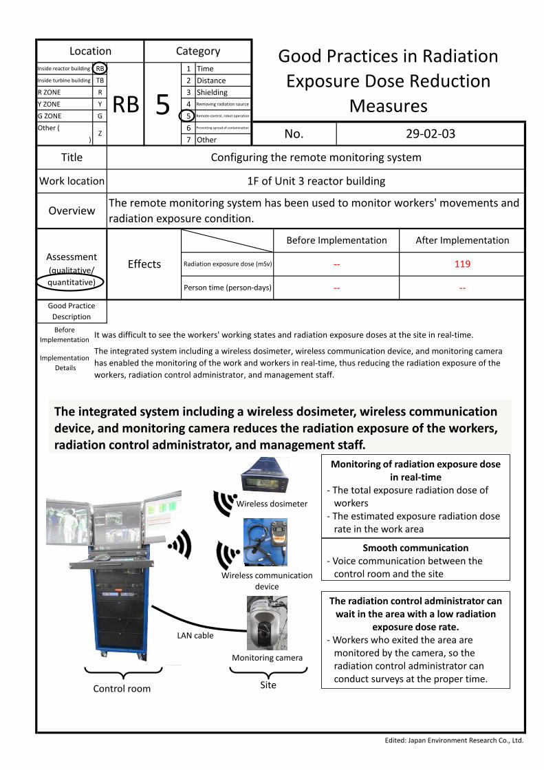
Implementation It was difficult to see the workers' working states and radiation exposure doses at the site in real-time.
Implementation Details
The integrated system including a wireless dosimeter, wireless communication device, and monitoring camerahas enabled the monitoring of the work and workers in real-time, thus reducing the radiation exposure of theworkers, radiation control administrator, and management staff.
Assessment Effects
Before Implementation After Implementation
Radiation exposure dose (mSv) -- 119(qualitative/quantitative) Person time (person-days)
Title Configuring the remote monitoring system
Work location 1F of Unit 3 reactor building
OverviewThe remote monitoring system has been used to monitor workers' movements andradiation exposure condition.
Location Category Good Practices in RadiationExposure Dose Reduction
MeasuresRB 5Z No. 29-02-03
The integrated system including a wireless dosimeter, wireless communication device, and monitoring camera reduces the radiation exposure of the workers, radiation control administrator, and management staff.
LAN cable
Wireless communication device
Monitoring camera
Wireless dosimeter
Monitoring of radiation exposure dose in real-time
- The total exposure radiation dose of workers
- The estimated exposure radiation doserate in the work area
Smooth communication- Voice communication between the
control room and the site
The radiation control administrator can wait in the area with a low radiation
exposure dose rate.- Workers who exited the area are
monitored by the camera, so theradiation control administrator canconduct surveys at the proper time.
Control room Site
Inside reactor building RB 1 TimeInside turbine building TB 2 DistanceR ZONE R 3 ShieldingY ZONE Y 4 Removing radiation source
G ZONE G 5 Remote-control, robot operation
Other ( 6 Preventing spread of contamination
) 7 Other
Edited: Japan Environment Research Co., Ltd.
-- --
Good PracticeDescription
BeforeImplementation
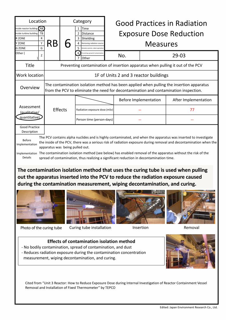
The PCV contains alpha nuclides and is highly contaminated, and when the apparatus was inserted to investigatethe inside of the PCV, there was a serious risk of radiation exposure during removal and decontamination when theapparatus was being pulled out.
ImplementationDetails
The contamination isolation method (see below) has enabled removal of the apparatus without the risk of thespread of contamination, thus realizing a significant reduction in decontamination time.
Assessment Effects
Before Implementation After Implementation
Radiation exposure dose (mSv) -- 77(qualitative/quantitative) Person time (person-days)
Title Preventing contamination of insertion apparatus when pulling it out of the PCV
Work location 1F of Units 2 and 3 reactor buildings
Overview The contamination isolation method has been applied when pulling the insertion apparatusfrom the PCV to eliminate the need for decontamination and contamination inspection.
Location Category Good Practices in RadiationExposure Dose Reduction
MeasuresRB 6Z No. 29-03
Cited from “Unit 3 Reactor: How to Reduce Exposure Dose during Internal Investigation of Reactor Containment VesselRemoval and Installation of Fixed Thermometer” by TEPCO
The contamination isolation method that uses the curing tube is used when pulling out the apparatus inserted into the PCV to reduce the radiation exposure caused during the contamination measurement, wiping decontamination, and curing.
Photo of the curing tube Insertion RemovalCuring tube installation
Effects of contamination isolation method- No bodily contamination, spread of contamination, and dust- Reduces radiation exposure during the contamination concentration
measurement, wiping decontamination, and curing.

Inside reactor building RB 1 TimeInside turbine building TB 2 DistanceR ZONE R 3 ShieldingY ZONE Y 4 Removing radiation source
G ZONE G 5 Remote-control, robot operation
Other ( 6 Preventing spread of contamination
) 7 Other
Edited: Japan Environment Research Co., Ltd.
-- --
Good PracticeDescriptionBefore
ImplementationThe periphery of the floor drain sump had a high radiation exposure dose rate when the workers carried in thesubmersible pump to B1F of the turbine building.
ImplementationDetails
The workers carried in the pump to B1F of the turbine building from 1F. The pump had less effect on the heaterdrain piping.
Assessment Effects
Before Implementation After Implementation
Radiation exposure doserate (mSv/h) 7 to 22 0.5 to 4.0
(qualitative/quantitative) Person time (person-days)
Title Changing the work place to an area with a low radiation exposure dose rate
Work location 1F of Unit 1 turbine building
Overview A submersible pump was carried in from 1F where the radiation exposure dose rate was low,but not from the middle part of B1F where the radiation exposure dose rate was high.
Location Category Good Practices in RadiationExposure Dose Reduction
MeasuresTB 2Z No. 29-04-01
Floor drain sump
Pump
1F (T.P.8743)
Middle part of B1F (T.P.3443)
B1F (T.P.443)
Transfer hose and other equipment
x 0.5 to 4.0mSv/h
x 7 to 22mSv/h
The pump was also carried in from 1F. The pump had less effect on the heater drain piping.
Work done by remote control from the area with a low radiation exposure dose rate

Inside reactor building RB 1 TimeInside turbine building TB 2 DistanceR ZONE R 3 ShieldingY ZONE Y 4 Removing radiation source
G ZONE G 5 Remote-control, robot operation
Other ( 6 Preventing spread of contamination
) 7 Other
Edited: Japan Environment Research Co., Ltd.
-- --
Good PracticeDescription
BeforeImplementation
The periphery of the floor drain sump (work area in B1F) had a high radiation exposure dose rate when the workerscut the interfering piping from B1F.
ImplementationDetails
Remote control was done about 10 m away to cut the piping from 1F where the radiation exposure dose rate wascomparatively low.
Assessment Effects
Before Implementation After Implementation
Radiation exposure doserate (mSv/h) 7 to 22 0.5 to 4.0
(qualitative/quantitative) Person time (person-days)
Title Changing the work place to an area with a low radiation exposure dose rate
Work location 1F of Unit 1 turbine building
Overview The interfering piping was cut off from 1F, where the radiation exposure dose rate was low, butnot from B1F, where the radiation exposure dose rate was high.
Location Category Good Practices in RadiationExposure Dose Reduction
MeasuresTB 5Z No. 29-04-02
The jigs for cutting the interfering piping (such as hydraulic cutters) were prepared, and the piping was cut from 1F, which had less effect on the heater drain piping.
1F (T.P.8743)
B1F (T.P.3443)
B1F (T.P.443)
T.P. -2057Hydraulic cutter
Removed at a level of T.P.8743
Pump installation positionInterfering piping
Heater drain piping and other parts
x 0.5 to 4.0mSv/h
x 7 to 22mSv/h
Work done by remote control from the area with a low radiation exposure dose rate
Inside reactor building RB 1 TimeInside turbine building TB 2 DistanceR ZONE R 3 ShieldingY ZONE Y 4 Removing radiation source
G ZONE G 5 Remote-control, robot operation
Other ( 6 Preventing spread of contamination
) 7 Other
Edited: Japan Environment Research Co., Ltd.
-- --
Good PracticeDescriptionBefore
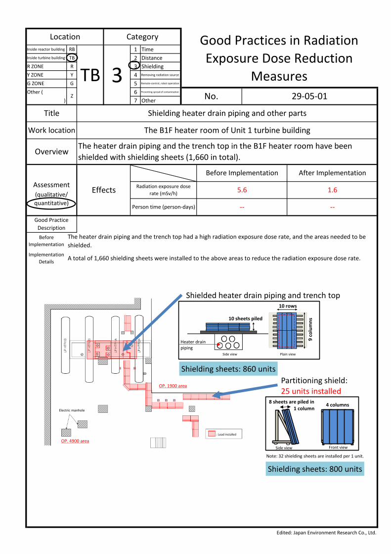
ImplementationThe heater drain piping and the trench top had a high radiation exposure dose rate, and the areas needed to beshielded.
ImplementationDetails A total of 1,660 shielding sheets were installed to the above areas to reduce the radiation exposure dose rate.
Assessment Effects
Before Implementation After Implementation
Radiation exposure doserate (mSv/h) 5.6 1.6
(qualitative/quantitative) Person time (person-days)
Title Shielding heater drain piping and other parts
Work location The B1F heater room of Unit 1 turbine building
OverviewThe heater drain piping and the trench top in the B1F heater room have beenshielded with shielding sheets (1,660 in total).
Location Category Good Practices in RadiationExposure Dose Reduction
MeasuresTB 3Z No. 29-05-01
Electric manhole
: Lead installed
OP. 1900 area
OP. 4900 area
Shielded heater drain piping and trench top
4 columns8 sheets are piled in1 column
Partitioning shield: 25 units installed
Side view Front view
Note: 32 shielding sheets are installed per 1 unit.
Shielding sheets: 860 units
Shielding sheets: 800 units
Heater drain piping
10 rows9
colu
mns10 sheets piled
Plain viewSide view

Inside reactor building RB 1 TimeInside turbine building TB 2 DistanceR ZONE R 3 ShieldingY ZONE Y 4 Removing radiation source
G ZONE G 5 Remote-control, robot operation
Other ( 6 Preventing spread of contamination
) 7 Other
Edited: Japan Environment Research Co., Ltd.
-- --
Good PracticeDescriptionBefore
ImplementationThe heater drain piping was the radiation source, and the work done around it had a higher risk of radiationexposure.
ImplementationDetails The radiation exposure has been reduced by shielding the piping and other parts with lead mats.
Assessment Effects
Before Implementation After Implementation
Radiation exposure dose (mSv) -- --(qualitative/quantitative) Person time (person-days)
Title Shielding heater drain piping and other parts
Work location The B1F heater room of Unit 1 turbine building
OverviewThe heater drain piping and other parts have been shielded because the pipingconnected to the condenser was the radiation source.
Location Category Good Practices in RadiationExposure Dose Reduction
MeasuresTB 3Z No. 29-05-02
The heater drain piping, electrical pit, and opening were shielded.
N
B1F of turbine building
: Shielding body
: Partitioning shield
Shielding the heater drain piping and other parts
The shielding in the diagram includes installationby several companies.
Reducing the radiation exposure dose in the unit installation area in the basement
Heater drain piping
Electrical pits
Opening
Turbine oil tank
Condenser (A)
Low-pressure feed water heater

Inside reactor building RB 1 TimeInside turbine building TB 2 DistanceR ZONE R 3 ShieldingY ZONE Y 4 Removing radiation source
G ZONE G 5 Remote-control, robot operation
Other ( 6 Preventing spread of contamination
) 7 Other
Edited: Japan Environment Research Co., Ltd.
-- --
Good PracticeDescriptionBefore
ImplementationThe inside of the condenser had a high radiation exposure dose rate, and thus the upper part of it also had a highradiation exposure dose rate.
ImplementationDetails
The condenser surface has been shielded to reduce the radiation exposure at the upper part of the condenserwhen the workers perform drilling and carry in a pump.
Assessment Effects
Before Implementation After Implementation
Radiation exposure dose (mSv) -- --(qualitative/quantitative) Person time (person-days)
Title Shielding the accessible area of the upper part of the condenser
Work location Around the condenser neck heater in 1F of Unit 1 turbine building
Overview The condenser surface has been shielded to reduce the radiation exposure at the upper part ofthe condenser.
Location Category Good Practices in RadiationExposure Dose Reduction
MeasuresTB 3Z No. 29-06
Radiation source direction
Condenser (B)Manhole cover opened
Existing hose
×2.0
Condenser B (shielding state)
Condenser (B)
Area for installing shields
Drilled part for carrying in a pump
Condenser B (shielding state)
Water with a high radiation exposure dose rate was stored in the condenser The area for carrying in the pump was shielded to reduce the radiation exposure dose rate.
Reducing the radiation exposure dose in the unit installation area in the basement

Inside reactor building RB 1 TimeInside turbine building TB 2 DistanceR ZONE R 3 ShieldingY ZONE Y 4 Removing radiation source
G ZONE G 5 Remote-control, robot operation
Other ( 6 Preventing spread of contamination
) 7 Other
Edited: Japan Environment Research Co., Ltd.
-- --
Good PracticeDescriptionBefore
ImplementationThe inside of the condenser had a high radiation exposure dose rate, and thus draining and transferring the dilutedwater also had the risk of a high radiation exposure dose rate.
ImplementationDetails The radiation exposure during transfer has been reduced by shielding the transfer lines with lead mats.
Assessment Effects
Before Implementation After Implementation
Radiation exposure dose (mSv) -- --(qualitative/quantitative) Person time (person-days)
Title Shielding the transfer lines of water stored in the condenser
Work location The 1F heater room of Unit 1 turbine building
Overview The transfer lines were shielded for transferring water stored in the condenser.
Location Category Good Practices in RadiationExposure Dose Reduction
MeasuresTB 3Z No. 29-07
Shielding state(transfer lines of water storedin the condenser)
N
1F of Unit 1 turbine building
Water with a high radiation exposure dose rate was stored in the condenser The radiation exposure during transfer has been reduced by installing shields to the transfer lines of the water stored in the condenser.
Area for installing shields

Inside reactor building RB 1 TimeInside turbine building TB 2 DistanceR ZONE R 3 ShieldingY ZONE Y 4 Removing radiation source
G ZONE G 5 Remote-control, robot operation
Other ( 6 Preventing spread of contamination
) 7 Other
Edited: Japan Environment Research Co., Ltd.
-- --
Good PracticeDescriptionBefore
ImplementationThe opening side of the heater room, which is the work area, had a comparatively high radiation exposure doserate.
ImplementationDetails Additional shielding mats were installed on the handrail of the opening to reduce the radiation exposure dose rate.
Assessment Effects
Before Implementation After Implementation
Radiation exposure doserate (mSv/h) 2.4 1.4
(qualitative/quantitative) Person time (person-days)
Title Shielding the opening around the condenser
Work location The 1F opening side of Unit 1 turbine building
OverviewShields were installed on the handrail of the opening of the heater room, which isthe remote control area.
Location Category Good Practices in RadiationExposure Dose Reduction
MeasuresTB 3Z No. 29-08
The remote control area on 1F was also shielded to further reduce the radiation exposure dose rate.
Opening
Handrail
: Existing shield area (16 sheets)
: Area for installing shields this time (20 sheets)
N
Unit 1 T/B 1FL
Radiation exposure dose rate around the opening reduction from 2.4 mSv/h to 1.4 mSv/h

Inside reactor building RB 1 TimeInside turbine building TB 2 DistanceR ZONE R 3 ShieldingY ZONE Y 4 Removing radiation source
G ZONE G 5 Remote-control, robot operation
Other ( 6 Preventing spread of contamination
) 7 Other
Edited: Japan Environment Research Co., Ltd.
-- --
Good PracticeDescriptionBefore
ImplementationThe heater drain piping and the trench top had a high radiation exposure dose rate, and the areas needed to beshielded.
ImplementationDetails The pre-assembled partitioning shields were used to reduce the installation time.
Assessment Effects
Before Implementation After Implementation
Radiation exposure doserate (mSv/h) 2.8 0.11
(qualitative/quantitative) Person time (person-days)
Title Installing pre-assembled partitioning shields
Work location B1F heater room of Unit 1 turbine building
Overview The heater drain piping and the trench top have been shielded with shielding sheets (1,660 in total). The pre-assembled partitioning shields were used to reduce the installation time.
Location Category Good Practices in RadiationExposure Dose Reduction
MeasuresTB 3Z No. 29-09-01
Folded state
Pre-assembled state
Lead being installed
Assembly completed
Installation of pre-assembled partitioning shields (image photos)

Inside reactor building RB 1 TimeInside turbine building TB 2 DistanceR ZONE R 3 ShieldingY ZONE Y 4 Removing radiation source
G ZONE G 5 Remote-control, robot operation
Other ( 6 Preventing spread of contamination
) 7 Other
Edited: Japan Environment Research Co., Ltd.
-- --
Good PracticeDescriptionBefore
ImplementationThe heater drain piping and the trench top had a high radiation exposure dose rate, and the areas needed to beshielded.
ImplementationDetails The pre-assembled partitioning shields were used to reduce the installation time.
Assessment Effects
Before Implementation After Implementation
Radiation exposure doserate (mSv/h) 2.8 0.11
(qualitative/quantitative) Person time (person-days)
Title Installing pre-assembled partitioning shields
Work location B1F heater room of Unit 1 turbine building
Overview The heater drain piping and the trench top have been shielded with the shielding sheets (1,660in total). The pre-assembled partitioning shields were used to reduce the installation time.
Location Category Good Practices in RadiationExposure Dose Reduction
MeasuresTB 3Z No. 29-09-02
Shielding sheetLead thickness: 3 mm/sheet
Weight: about 16 kg/sheet
Assembly partitioning sheet
Lead thickness: 24 mm
Lead weight: about 512 kg/unit
Frame weight: about 100 kg/unit
Assembly time: about 10 min/unit
Movable: with casters
Separable: into 3 parts
Overview of assembly partitioning shields
Shielding sheet: 8 units Shielding sheet: 4 columns

Inside reactor building RB 1 TimeInside turbine building TB 2 DistanceR ZONE R 3 ShieldingY ZONE Y 4 Removing radiation source
G ZONE G 5 Remote-control, robot operation
Other ( 6 Preventing spread of contamination
) 7 Other
Edited: Japan Environment Research Co., Ltd.
-- --
Good PracticeDescriptionBefore
ImplementationThe heater room had a high radiation exposure dose rate because of the influence of the sludge widelyaccumulated on the floor.
ImplementationDetails
The accumulated sludge was removed by a remotely operated device to reduce the radiation exposure rate in theheater room.
Assessment Effects
Before Implementation After Implementation
Radiation exposure dose (mSv) -- --(qualitative/quantitative) Person time (person-days)
Title Removing accumulated sludge
Work location B1F heater room of Unit 1 turbine building
Overview The radioactive sludge accumulated on the heater room floor was removed.
Location Category Good Practices in RadiationExposure Dose Reduction
MeasuresTB 5Z No. 29-10-01
[Driving unit]- Collects the sludge on the floor. - The sludge is transported in a narrow area usinghigh-pressure water, and wall equipment is decontaminated by spraying water.
- The sludge is moisturized by spraying water overa wide angle.
[Relay unit]- Monitors the driving unit, and pulls the cable.
Device control room
1F (T.P.8743)
B1F (T.P.3443)
Decontamination head
High-pressure jet nozzle
SludgeDriving unit Relay unit
[Driving unit]- Weight: 48 kg- Dimensions: L830 x W413 x H466 mm
(excluding the head part)
[Relay unit]- Weight: 44 kg- Dimensions: L950 x W413 x H919 mm
Removing sludge on floor (decontamination)The sludge on the floor was removed with a small remotely operated device.[Overview of sludge collection]
Reducing the radiation exposure dose in the unit installation area in the basement
From the website of TEPCO

Inside reactor building RB 1 TimeInside turbine building TB 2 DistanceR ZONE R 3 ShieldingY ZONE Y 4 Removing radiation source
G ZONE G 5 Remote-control, robot operation
Other ( 6 Preventing spread of contamination
) 7 Other
Edited: Japan Environment Research Co., Ltd.
-- --
Good PracticeDescriptionBefore
ImplementationThe heater room had a high radiation exposure dose rate because of the influence of the sludge widelyaccumulated on the floor.
ImplementationDetails
After removing the sludge by a remotely operated device, workers wiped the heater chamber floor to furtherreduce the radiation exposure dose rate.
Assessment Effects
Before Implementation After Implementation
Radiation exposure dose (mSv) -- --(qualitative/quantitative) Person time (person-days)
Title Removing accumulated sludge
Work location B1F heater room of Unit 1 turbine building
Overview The radioactive sludge accumulated on the heater room floor was removed.
Location Category Good Practices in RadiationExposure Dose Reduction
MeasuresTB 4Z No. 29-10-02
N
T/B B1F
Being wiped
Removing sludge on floor (decontamination)
After being wiped
After removing the sludge by a remote device, workers wiped the heater room floor.
Reducing the radiation exposure dose in the unit installation area in the basement

Inside reactor building RB 1 TimeInside turbine building TB 2 DistanceR ZONE R 3 ShieldingY ZONE Y 4 Removing radiation source
G ZONE G 5 Remote-control, robot operation
Other ( 6 Preventing spread of contamination
) 7 Other
Edited: Japan Environment Research Co., Ltd.
-- --
Good PracticeDescriptionBefore
ImplementationThe water stored in the condenser had a high radiation exposure dose rate, and therefore, had a higher risk ofradiation exposure when being transferred.
ImplementationDetails
The work was conducted after diluting the water stored in the condenser to a radioactive concentration of about1/30 of the original value.
Assessment Effects
Before Implementation After Implementation
Radiation exposure dose (mSv) -- --(qualitative/quantitative) Person time (person-days)
Title Diluting the water with a high radiation exposure dose rate that was stored in the condenser.
Work location Around the condenser neck heater in B1F of Unit 1 turbine building
OverviewAfter being diluted, the water stored in the condenser was transferred and drainedto reduce radiation exposure.
Location Category Good Practices in RadiationExposure Dose Reduction
MeasuresTB 4Z No. 29-11
Repeated
To condenser pump
From HD piping (dilution water)
From HD piping (dilution water)
From HD piping (dilution water)
To condenser pump
To condenser pump
To stagnant water process (drained by temporary pump)
Dilution water flows from HD piping
Reducing the radiation exposure dose in the unit installation area in the basement
Water with a high radiation exposure dose rate was stored in the condenser Dilution water was injected into the water stored in the condenser to reduce its radioactivity concentration to about 1/30 of the original value, and thus reduce the radiation exposure dose rate during transfer.
From the website of TEPCO
The work has been completed with less radiation exposure by shielding the pump installation area and transfer line.
Heater
Dilution water injected from heaterTo building stagnant water
Heater drain piping
Condenser
Current water level
Pump
Steps 2 and 4Transfer of stored water and dilution water in condenserStep 1Pump installation
Step 3Dilution water injection
Hot well top plate

Inside reactor building RB 1 TimeInside turbine building TB 2 DistanceR ZONE R 3 ShieldingY ZONE Y 4 Removing radiation source
G ZONE G 5 Remote-control, robot operation
Other ( 6 Preventing spread of contamination
) 7 Other
Edited: Japan Environment Research Co., Ltd.
-- --
Good PracticeDescriptionBefore
ImplementationThe quickest route to the work area included the area with a high radiation exposure dose rate and had a higherrisk of radiation exposure.
ImplementationDetails
The route with a low radiation exposure dose rate was set beforehand and signs were put on the route to prevententering the area with a high radiation exposure dose rate.
Assessment Effects
Before Implementation After Implementation
Radiation exposure dose (mSv) -- --(qualitative/quantitative) Person time (person-days)
Title Setting and indicating the access route
Work location All of 1F of Unit 1 turbine building
OverviewThe route for entering and exiting the work area was set beforehand so the workers can pass through the areawith a low radiation exposure dose rate. Signs were put on the route to prevent entering the area with a highradiation exposure dose rate.
Location Category Good Practices in RadiationExposure Dose Reduction
MeasuresTB 7Z No. 29-12
The access route to the condenser room basement with a low radiation exposure dose rate was set and indicated.
N
1F of Unit 1 turbine building
Access route
Setting and indicating the access route with a low radiation exposure dose rate
Sign of access route

Inside reactor building RB 1 TimeInside turbine building TB 2 DistanceR ZONE R 3 ShieldingY ZONE Y 4 Removing radiation source
G ZONE G 5 Remote-control, robot operation
Other ( 6 Preventing spread of contamination
) 7 Other
Edited: Japan Environment Research Co., Ltd.
-- --
Good PracticeDescriptionBefore
Implementation(1) The existing scaffoldings were in the area with a high radiation exposure dose rate.(2) When removing rubble, displaying the radiation exposure dose was difficult because the work was conducted outside.
ImplementationDetails
(1) New scaffoldings were installed in the areas with a low radiation exposure dose rate(2) The radiation exposure dose was displayed on the rooftop floor in different colors.
Assessment Effects
Before Implementation After Implementation
Radiation exposure dose (mSv) -- --(qualitative/quantitative) Person time (person-days)
Title Setting lifting facilities in areas with a low radiation exposure dose rate
Work location The rooftops of Units 1 and 2 turbine buildings
OverviewThe installation of new scaffoldings was conducted before beginning the application of waterproof coating tothe rooftops of the turbine buildings and visual control of exposure radiation dose rate was implementedduring the work.
Location Category Good Practices in RadiationExposure Dose Reduction
MeasuresR 2Z No. 29-13
Indication of radiation exposure dose rates
Installation of lifting facilities
Conv
entio
nal l
iftin
g fa
cilit
ies
posit
ions
Unit 1 Unit 2 Red: above 2.5 mSv/h
Inside reactor building RB 1 TimeInside turbine building TB 2 DistanceR ZONE R 3 ShieldingY ZONE Y 4 Removing radiation source
G ZONE G 5 Remote-control, robot operation
Other ( 6 Preventing spread of contamination
) 7 Other
Edited: Japan Environment Research Co., Ltd.
-- --
Good PracticeDescriptionBefore
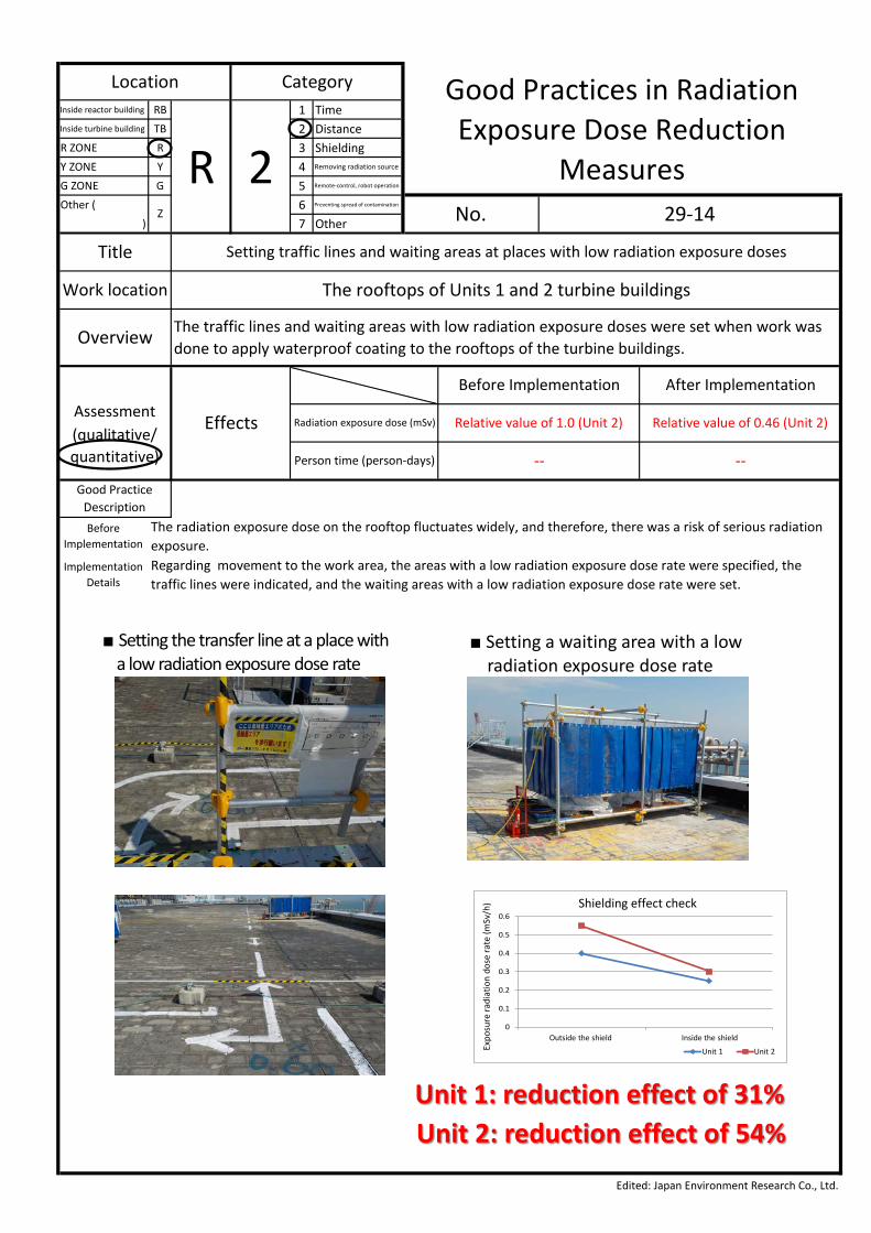
ImplementationThe radiation exposure dose on the rooftop fluctuates widely, and therefore, there was a risk of serious radiationexposure.
ImplementationDetails
Regarding movement to the work area, the areas with a low radiation exposure dose rate were specified, thetraffic lines were indicated, and the waiting areas with a low radiation exposure dose rate were set.
Assessment Effects
Before Implementation After Implementation
Radiation exposure dose (mSv) Relative value of 1.0 (Unit 2) Relative value of 0.46 (Unit 2)(qualitative/quantitative) Person time (person-days)
Title Setting traffic lines and waiting areas at places with low radiation exposure doses
Work location The rooftops of Units 1 and 2 turbine buildings
Overview The traffic lines and waiting areas with low radiation exposure doses were set when work wasdone to apply waterproof coating to the rooftops of the turbine buildings.
Location Category Good Practices in RadiationExposure Dose Reduction
MeasuresR 2Z No. 29-14
Unit 1: reduction effect of 31%Unit 2: reduction effect of 54%
0
0.1
0.2
0.3
0.4
0.5
0.6
遮へい外 遮へい内
1号機 2号機
線量率(m
Sv/h)
遮へい効果確認
■ Setting the transfer line at a place witha low radiation exposure dose rate
■ Setting a waiting area with a lowradiation exposure dose rate
Shielding effect check
Outside the shield Inside the shield
Unit 1 Unit 2Expo
sure
radi
atio
n do
se ra
te (m
Sv/h
)

Inside reactor building RB 1 TimeInside turbine building TB 2 DistanceR ZONE R 3 ShieldingY ZONE Y 4 Removing radiation source
G ZONE G 5 Remote-control, robot operation
Other ( 6 Preventing spread of contamination
) 7 Other
Edited: Japan Environment Research Co., Ltd.
-- --
Good PracticeDescriptionBefore
Implementation The site control office required shielding because the reactor building was the radiation source.
ImplementationDetails
The lead mats and partitioning shields were installed on the ceiling and side surfaces so as to cover the site controloffice.
Assessment Effects
Before Implementation After Implementation
Radiation exposure dose (mSv) Relative value of 1.0 Relative value of 0.3 (228)(qualitative/quantitative) Person time (person-days)
Title Shielding the periphery of Unit 3 reactor building
Work location The west yard of Unit 3 reactor building
OverviewFor the internal investigation of the Unit 3 PCV, the site control office has been set up in the west yard of thereactor building. The area is affected by radiation from the reactor building, and therefore, was shielded withlead partitioning shields.
Location Category Good Practices in RadiationExposure Dose Reduction
MeasuresR 3Z No. 29-15
N SE
W
Sky
Ground
13%
21%
9%
11%
37%
9%Percentage of the air dose rate in different directions
in the planned installation area
Installation of site control office (at 1st entry)
Lead plate mats were installed around the temporary control office to reducethe air dose rate inside the control office.
The air dose rate inside the control officewas reduced by 70% compared to beforeshielding installation.
Unit 2 side (single: 63
sheets)
Back (single: 78 sheets)
Ceiling (double: 208 sheets)
Unit 4 side (double: 126 sheets)
Front (7 ALARA screens: 112 sheets)

Inside reactor building RB 1 TimeInside turbine building TB 2 DistanceR ZONE R 3 ShieldingY ZONE Y 4 Removing radiation source
G ZONE G 5 Remote-control, robot operation
Other ( 6 Preventing spread of contamination
) 7 Other
Edited: Japan Environment Research Co., Ltd.
-- --
Good PracticeDescriptionBefore
ImplementationRadiation is emitted not just from the ground but also from the upper part of the turbine building; therefore, thework area also needed upper shielding.
ImplementationDetails
Concrete retaining walls and lead plates were used to install the shielding walls and to shield the roof. The workerswore shielding vests.
Assessment Effects
Before Implementation After Implementation
Radiation exposure dose (mSv) -- --(qualitative/quantitative) Person time (person-days)
Title Shielding for radioactive substances from the upper part of Unit 3 turbine building
Work location On the seaside of Unit 3 turbine building
Overview The work area and ceiling parts were shielded with concrete retaining walls and lead plates toshield against radiation (gamma rays) from the turbine buildings.
Location Category Good Practices in RadiationExposure Dose Reduction
MeasuresR 3Z No. 29-16
(1) How to shield against radiation- Ground => crushed stone, iron plates- Air => concrete retaining wall, lead mats
Unit 3 Unit 2
Crushed stone and iron plates laid
Lead mats installed
on the roof
Concrete retaining walls
Radial rays from the upper part of Unit
Lead mats
Tungsten vest
(2) Isolation from the position with a highradiation exposure dose rate
(3) Tungsten vest (shield)

Inside reactor building RB 1 TimeInside turbine building TB 2 DistanceR ZONE R 3 ShieldingY ZONE Y 4 Removing radiation source
G ZONE G 5 Remote-control, robot operation
Other ( 6 Preventing spread of contamination
) 7 Other
Edited: Japan Environment Research Co., Ltd.
-- --
Good PracticeDescriptionBefore
Implementation The tank needed shielding because there was a high beta dose rate inside.
ImplementationDetails
When the workers entered the tank, the bottom plate was shielded with rubber mats and the side plate wasshielded with concrete panels and aluminum plates to shield against the beta rays inside the tank.
Assessment Effects
Before Implementation After Implementation
Radiation exposure dose rate insidethe tank (mSv/h) 89.4 2.4
(qualitative/quantitative) Person time (person-days)
Title Shielding for beta rays inside the flange tank
Work location Flange tank disassembly area in the yard
Overview When the workers entered the tank, the bottom plate was shielded with rubber mats and theside plate was shielded with concrete panels and aluminum plates.
Location Category Good Practices in RadiationExposure Dose Reduction
MeasuresR 3Z No. 29-17
Shielding vest
Measurement result of dose rate inside C10 tank(measurement area: 50 cm from the side plate,
1.2 m from the floor)Black: before implementation
Red: after implementation
X75.0
X45.0
X90.0
X90.0
X85.0
X90.0
Measure: installation of shielding materials- Install rubber mats on the bottom of the tank.- Install concrete panels and aluminum plates on the side plate ofthe tank
Reduction effect (average value of dose equivalent rates)Before implementation: 89.4 mSv/hAfter implementation: 2.4 mSv/h (reduced by 97%)
×150.0
X130.0
1.2
Unit: mSv/h
1.5
5.0
6.02.0
3.0
2.0
2.0

Inside reactor building RB 1 TimeInside turbine building TB 2 DistanceR ZONE R 3 ShieldingY ZONE Y 4 Removing radiation source
G ZONE G 5 Remote-control, robot operation
Other ( 6 Preventing spread of contamination
) 7 Other
Location Category Good Practices in RadiationExposure Dose Reduction
MeasuresR 3Z No. 29-18
Title Adopting shielding trolleys
Work location The rooftops of Units 1 and 2 turbine buildings
OverviewThe shielding trolleys were adopted during work to apply waterproof coating to therooftops of the turbine buildings.
Assessment Effects
Before Implementation After Implementation
Radiation exposure dose (mSv) Relative value of 1.0 Relative value of 0.46(qualitative/quantitative) Person time (person-days)
Edited: Japan Environment Research Co., Ltd.
-- --
Good PracticeDescriptionBefore
Implementation The reactor building adjacent to the rooftop floor was still the radiation source even after rubble removal.
ImplementationDetails Trolleys with shields were adopted and workers did the coating work from inside the trolleys.
Reduction effect of 54%
[Driver]
[Person who prepared the coating]
[Sprayer]
Shielding effect check
Before shielding After shielding
Expo
sure
radi
atio
n do
se
rate
(mSv
/h)
Driver seat SprayerPerson who

Inside reactor building RB 1 TimeInside turbine building TB 2 DistanceR ZONE R 3 ShieldingY ZONE Y 4 Removing radiation source
G ZONE G 5 Remote-control, robot operation
Other ( 6 Preventing spread of contamination
) 7 Other
Location Category Good Practices in RadiationExposure Dose Reduction
MeasuresR 4Z No. 29-19-01
Title Removing rubble before applying waterproof coating
Work location The rooftops of Units 1 and 2 turbine buildings
OverviewThe rubble was removed before applying waterproof coating to the rooftops of theturbine buildings.
Assessment Effects
Before Implementation After Implementation
Radiation exposure dose (mSv) -- --(qualitative/quantitative) Person time (person-days)
Edited: Japan Environment Research Co., Ltd.
-- --
Good PracticeDescriptionBefore
Implementation The turbine building rooftop were scattered with rubble and had a high radiation exposure dose rate.
ImplementationDetails Other work was performed after removing the rubble and reducing the overall radiation exposure dose rate.
The exposure radiation dose rate in the area before and after the rubble removal
Beforerubble removal
Unit 1 T/B rooftop
1.00 (120 cm above shield)0.60 ( surface on the shield)
×0.50
×1.10
×1.80 ×1.20×0.70
×1.20
1.00 (120 cm above shield)0.60 ( surface on the shield)
×0.50
×1.10
×1.20×0.70
Afterrubble removal
15.01.00.5 1.5 2.0 2.5 3.00.5 1.0 1.5 2.0 2.5 3.0 15.0 mSv/h

Inside reactor building RB 1 TimeInside turbine building TB 2 DistanceR ZONE R 3 ShieldingY ZONE Y 4 Removing radiation source
G ZONE G 5 Remote-control, robot operation
Other ( 6 Preventing spread of contamination
) 7 Other
Location Category Good Practices in RadiationExposure Dose Reduction
MeasuresR 4Z No. 29-19-02
Title Removing rubble before applying waterproof coating
Work location The rooftops of Units 1 and 2 turbine buildings
OverviewPhotos showing progress (before rubble removal after rubble removal after applying waterproof coating)
Assessment Effects
Before Implementation After Implementation
Radiation exposure dose (mSv) -- --(qualitative/quantitative) Person time (person-days)
Edited: Japan Environment Research Co., Ltd.
-- --
Good PracticeDescription
Before rubble removal After rubble removal
After applyingwaterproof coating

Inside reactor building RB 1 TimeInside turbine building TB 2 DistanceR ZONE R 3 ShieldingY ZONE Y 4 Removing radiation source
G ZONE G 5 Remote-control, robot operation
Other ( 6 Preventing spread of contamination
) 7 Other
Location Category Good Practices in RadiationExposure Dose Reduction
MeasuresR 5Z No. 29-20
Title Using a remote sprayer to control spreading of the contamination on the inner surface of the tank
Work location Flange tank disassembly area in the yard
Overview The flange tank disassembly work exposes contaminated parts; therefore, a remote sprayer hasbeen developed to control the spread of the contamination and to reduce labor hours.
Assessment Effects
Before Implementation After Implementation
Radiation exposure dose (mSv) 42.3 per tank 0 per tank(qualitative/quantitative) Person time (person-days)
Edited: Japan Environment Research Co., Ltd.
-- --
Good PracticeDescriptionBefore
ImplementationBefore starting the tank disassembly work, the inner surface needs to be sprayed with a coating so thecontamination spread can be controlled; however, entering the tank presented problems of safety and workload.
ImplementationDetails
The sprayer has been developed so that workers can spray coating on the inner surface of the tank withoutentering it.
Installation of spraying device Spray completionSpraying state(water-based epoxy anticorrosive material)
Overall appearance of device
Nozzle for side wall
6 nozzles for bottom plate
Turntable(circumferential direction)

Inside reactor building RB 1 TimeInside turbine building TB 2 DistanceR ZONE R 3 ShieldingY ZONE Y 4 Removing radiation source
G ZONE G 5 Remote-control, robot operation
Other ( 6 Preventing spread of contamination
) 7 Other
Location Category Good Practices in RadiationExposure Dose Reduction
MeasuresR 6Z No. 29-21
Title Contamination management during flange tank disassembly
Work location Preventing contamination spread and internal exposure when exiting the tank
OverviewAn exit area was provided to prevent the contamination spread. The workers’ equipment was removed bydedicated radiation control administrators to prevent internal contamination and body contamination ofworkers while undressing.
Assessment Effects
Before Implementation After Implementation
Radiation exposure dose (mSv) -- --(qualitative/quantitative) Person time (person-days)
Edited: Japan Environment Research Co., Ltd.
-- --
Good PracticeDescriptionBefore
ImplementationThe inside of the tank is highly contaminated. There was a risk of contamination spread, internal contamination,and body contamination when the workers exit the tank or undress.
ImplementationDetails
An exit area was provided and the workers’ equipment was removed by dedicated radiation control administratorsin the exit area to prevent contamination spread, internal contamination, and body contamination.
Equipment exchange place Anorak removal by dedicated radiation control administrator
Place to keep boots for work site
Equipment check by dedicated radiation control administrator
The following measures have been thoroughly carried out:(1) Dividing the work area into several zones(2) Making equipment checks by dedicated radiation control
administrators(3) Making contamination inspections after work
Inside reactor building RB 1 TimeInside turbine building TB 2 DistanceR ZONE R 3 ShieldingY ZONE Y 4 Removing radiation source
G ZONE G 5 Remote-control, robot operation
Other ( 6 Preventing spread of contamination
) 7 Other
Location Category Good Practices in RadiationExposure Dose Reduction
MeasuresR 7Z No. 29-22
Title Reducing workload by developing and using the superfluid concrete material
Work location On the seaside of Unit 3 turbine building
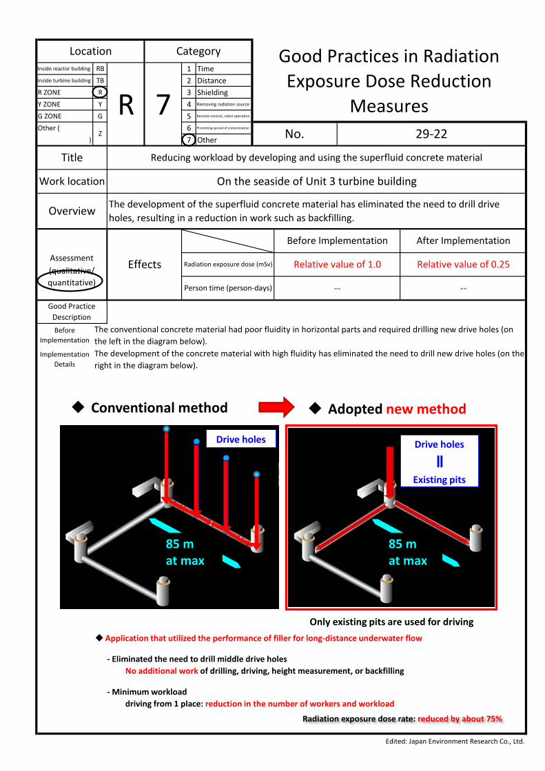
Overview The development of the superfluid concrete material has eliminated the need to drill driveholes, resulting in a reduction in work such as backfilling.
Assessment Effects
Before Implementation After Implementation
Radiation exposure dose (mSv) Relative value of 1.0 Relative value of 0.25(qualitative/quantitative) Person time (person-days)
Edited: Japan Environment Research Co., Ltd.
-- --
Good PracticeDescriptionBefore
ImplementationThe conventional concrete material had poor fluidity in horizontal parts and required drilling new drive holes (onthe left in the diagram below).
ImplementationDetails
The development of the concrete material with high fluidity has eliminated the need to drill new drive holes (on theright in the diagram below).
Conventional method
Drive holes
85 m at max
Drive holes
Existing pits
Only existing pits are used for driving
85 m at max
Drive holes
Existing pits
Application that utilized the performance of filler for long-distance underwater flow
- Eliminated the need to drill middle drive holesNo additional work of drilling, driving, height measurement, or backfilling
- Minimum workloaddriving from 1 place: reduction in the number of workers and workload
Radiation exposure dose rate: reduced by about 75%
Adopted new method
Inside reactor building RB 1 TimeInside turbine building TB 2 DistanceR ZONE R 3 ShieldingY ZONE Y 4 Removing radiation source
G ZONE G 5 Remote-control, robot operation
Other ( 6 Preventing spread of contamination
) 7 Other
Location Category Good Practices in RadiationExposure Dose Reduction
MeasuresR 7Z No. 29-23
Title Mechanizing waterproof coating
Work location The rooftops of Units 1 and 2 turbine buildings
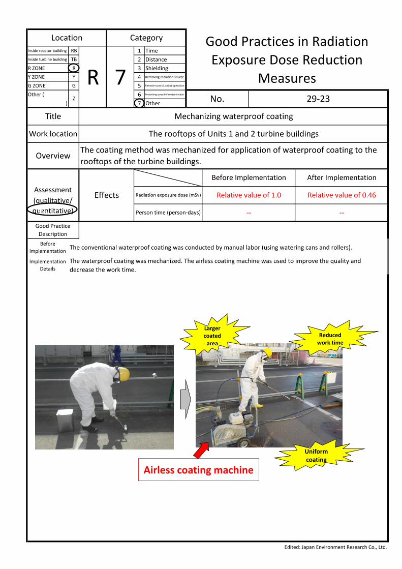
OverviewThe coating method was mechanized for application of waterproof coating to therooftops of the turbine buildings.
Assessment Effects
Before Implementation After Implementation
Radiation exposure dose (mSv) Relative value of 1.0 Relative value of 0.46(qualitative/quantitative) Person time (person-days)
Edited: Japan Environment Research Co., Ltd.
-- --
Good PracticeDescriptionBefore
Implementation The conventional waterproof coating was conducted by manual labor (using watering cans and rollers).
ImplementationDetails
The waterproof coating was mechanized. The airless coating machine was used to improve the quality anddecrease the work time.
あs
Reducedwork time
Uniform coating
Airless coating machine
Larger coated
area
FY2017 Project to Enhance the International Transmission of Radioactivity-Related Information on the Workers at TEPCO Holdings’ Fukushima Daiichi Nuclear Power PlantAssignee: Japan Environment Research Co., Ltd.
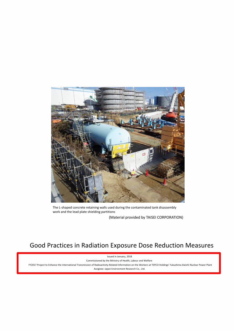
Good Practices in Radiation Exposure Dose Reduction MeasuresIssued in January, 2018
Commissioned by the Ministry of Health, Labour and Welfare
The L-shaped concrete retaining walls used during the contaminated tank disassembly work and the lead plate shielding partitions
(Material provided by TAISEI CORPORATION)