gost 31938-2012 interstate council for …gost 31938-2012 3 standard, relevant notification will be...
TRANSCRIPT

GOST 31938-2012
1
INTERSTATE COUNCIL FOR STANDARDIZATION, METROLOGY AND
CERTIFICATION
(ISC)
INTERSTATE STANDARD GOST 31938 - 2012
FIBRE-REINFORCED POLYMER BAR FOR CONCRETE REINFORCEMENT
General technical specifications
(ISO 10406-1:2008, NEQ)
Official publication
/Seal: territorial subdivision of propagation of regulatory technical documentation and scientific
and engineering information No 1. Moscow.* Copy is an official document* Illegible/
Moscow
Standartinform
2014

GOST 31938-2012
2
Introduction
Goals, main principles, and standard operating procedures of interstate standardization in
construction are established by GOST 1.0—92 «State System for Standardization of Russion
Federation. Basic principles» and GOST 1.2—2009 « Interstate system for standardization.
Interstate standards, rules and recommendations on interstate standardization. Rules for
development, taking over, application, renovation and cancellation»
Information on the standard
1 DEVELOPED BY RESEARCH INSTITUTE OF CONCRETE AND REINFORCED
CONCRETE (NIIZHB) NAMED A.A. GVOZDEV and Reinforced Concrete “Concrete and
Reinforced Concrete Research Institute of Moscow”, “Research Centre of Construction” JSC,
“Biysk factory of glass-fibre reinforced plastics” LLC with the participation of “TMB” LLC
2 INTEGRATED BY Interoperability Technical Committee ТK 465 “Construction”
3 APPROVED BY Interstate Scientific and Technical Commission for Standardization,
Technical rate setting and Compliance assessment in Construction (proceedings of 18 December,
2012 No. 41)
For acceptance voted:
Short name of country
acc. to MK (ISO 3166)
004-97
Country code acc. to
MK (ISO 3166) 004-97
Short name of State Administrative Body
for Construction
Azerbaijan AZ State Committee for Construction
Armenia AM Ministry of Urban planning
Belarus BY Ministry of Architecture and Construction
Kirghizia KG State Committee for Construction
Moldova MD State Committee for Construction
Russia RU Ministry of Regional Development
Tajikistan TJ Construction and Architecture Agency and
affiliated to the government
Uzbekistan YZ State Committee of Architecture and
Construction
4 This standard is developed on the basic of the main statutory regulations ISO 10406-1:2009
Fibre-reinforced polymer (FRP) reinforcement of concrete — Test methods — Part 1: FRP bars
and grids in terms of test methods.
Degree of conformity — inequivalent (NEQ)
5 By order of Federal Agency on Technical Regulating and Metrology dated 27 December, 2012
No. 2004-st interstate standard GOST 31938 -2012 has been put into effect as a national standard
of the Russia Federation since 1 January, 2014.
6 PUT INTO EFFECT FOR THE FIRST TIME
Information on changes to this standard is published in annual reference index “National
standards” (as of 1 January of the present year), and amendment text — in monthly reference
index “National standards”. In the case of oversight (replacement) or cancellation of this

GOST 31938-2012
3
standard, relevant notification will be published in monthly reference index “National
standards”. You can also find relevant information, notification and texts in information system
of common use — at official website of Federal Agency on Technical Regulating and Metrology
on the internet
© Standartinform, 2014
In the Russian Federation this standard cannot be reproduced, duplicated, or extended in whole
or in part as official publication without permission of Federal Agency on Technical Regulating
and Metrology

GOST 31938-2012
4
Contents
1 Scope 1
2 Normative references 1
3 Terms and definitions 2
4 Classification, basic parameters and dimensions 4
5 Technical specifications 5
6 Safety and environmental requirements 7
7 Acceptance rules 7
8 Control methods 9
9 Shipping and storage 10
10 Manufacturer's guarantee 10
Annex A (reference) Nominal diameter test method 11
Annex B (reference) Axial tension test method 13
Annex C (reference) Compression test method 16
Annex D (reference) Transverse shear strength test method 19
Annex E (reference) Test of limit bond strength to concrete 22
Annex F (reference) Alkali resistance accelerated test method 28
Annex G (reference) Maximum operating temperature test method 31
Annex H (reference) Passport form 36
Bibliography 37

GOST 31938-2012
1
INTERSTATE STANDARD
FIBRE-REINFORCED POLYMER BAR FOR CONCRETE REINFORCEMENT
General specifications
Date of introduction —2014—01—01
1 Scope
This standard establishes General specifications and is applied to fibre-reinforced
polymer ribbed bar (FRP bar) meant for reinforcement of conventional and restressed of building
constructions and elements, used in mediums with different attack degrees, agreeable to the
standards of fire resistance as per GOST Standard 30247 and fire safety as per GOST Standard
30403.
This standard is not applied to composite polymeric bars of smooth airfoil and composite
polymeric flexible couplers.
2 Normative references
The following references to standards are used in this standard:
GOST 8.207—76 State system for ensuring the uniformity of measurements. Direct
measurements with multiple observations. Methods of processing the results of observations.
Basic principles
GOST 12.1.044—89 Fire and explosion hazard of substances and materials.
Nomenclature of indices and methods of their determination
GOST 17.2.3.02—78 Regulations for establishing permissible emissions of noxious
pollutants from industrial enterprises
GOST 166—89 (ISO 3599—76) Vernier callipers. Specifications
GOST 427—75 Measuring metal rules. Basic parameters and dimensions. Specifications
GOST 3560—73 Sealing tape
GOST 4651—82 Plastics. Compression test method
GOST 6507—90 Micrometers. Specifications
GOST 7502—98 Measuring metal tapes. Specifications
GOST 10884—94 Thermomechanically hardened steel bars for reinforced concrete
constructions. Specifications
GOST 12004—81 Reinforcing-bar steel. Tensile test methods
GOST 12423—66 Plastics. Standard atmospheres for conditioning of test specimens
(sample)
GOST 14192—96 Marking of cargoes
GOST 14359—69 Plastics. Testing method. General requirements of the methods of
mechanical testing
GOST 15139—69 Plastics. Methods for the determination of density (volume mass)
GOST 15150—69 Machines, instruments and other industrial products. Modifications for
different climatic regions. Categories, operating, storage and transportation conditions as to
environment climatic aspects influence
GOST 16504—81 The state system of testing products. Product test and quality
inspection. General terms and definitions
GOST 17308—88 Twine. Specifications
Official publication
GOST 28840—90 Machines for tension, compression and bending testing of materials.
General technical requirements
GOST 31938-2012
2
GOST 30108—94 Building materials and elements. Determination of specific activity of
natural radioactive nuclei
GOST 30247.0—94 Elements of building constructions. Fire resistance tests methods.
General requirements
GOST 30403—96 Building structures. Fire hazard test methods
Note — When applying this standard you are advised to check if reference standards are
in force in information system of common use — at official website of Federal Agency on
Technical Regulating and Metrology on the internet or annual reference index “National
standards”, which is published as of 1 January of the present year, and releases of monthly
reference index “National standards” for the present year. If reference standard is replaced
(changed), when applying the standard you should follow replaced (changed) standard. If
reference standard is cancelled without its replacement, provision where there is a reference to it,
is applied without touching this reference.
3 Terms and definitions
Terms in this standard are applied per GOST Standard 10884 and GOST 12004, as well
as the following terms with relevant definitions:
3.1 composite: Solid product comprised of two or more materials that are different from
each other on form and/or phase state, and/or chemical composition, and/or properties fastened
together, as a rule, with physical link and having interface between obligatory material (matrix)
and their fillers, including reinforcing fillers.
Note — Matrix and composite filler form single structure and act jointly providing
necessary properties of end item for its functional purpose in the best possible way.
3.2 matrix of polymer composite; matrix. A structure made of hardened thermosetting
resin that provides wholeness of polymer composite, responsible for transmission and
distribution of tensions in reinforcing filler, and defines heat stability, moisture resistance, fire
resistance and chemical stability of polymer composite.
3.3 thermosetting resin: resin, which when hardening on exposure to temperatures
and/or due to chemical reaction irreversibly converts to hard, infusible and insoluble material
with three-dimensional grid-type structure.
Note — Thermosetting resins refer to unsaturated polyester, epoxy, vinylester, phenolic
and other types of organic resins.
3.4 filler of thermosetting resin; filler; Material or product connected with
thermosetting resin prior to hardening process to change or give required properties to resin
and/or matrix, or reduce the value of end production.
3.5 reinforcing agent: Material or article connected with thermosetting resin prior to
hardening process to improve physical and mechanical characteristics of polymer composite.
Notes
1 “Reinforcing agent” in this standard means reinforcing filler made of continuous fibre.
This term is not a synonym to the term “filler”.
2 Continuous reinforcing agents of glass fibre, basalt fibre, carbon and aramid fibre are
used to produce FRP bars.
3.6 fibre: Flexible extensive, continuous and solid object of limited length with small
cross dimensions in relation to length, being applied for production of fibrous materials meant
for polymer composites reinforcement.
Notes
1 Cross dimensions refer to thickness or diameter of fibre.
2 Depending on manufacturing process, there are continuous or staple fibres.
3.7 glass fibre: Fibre for polymer composites reinforcement generated from melt of

GOST 31938-2012
3
inorganic glass.
3.8 basalt fibre: Fibre for polymer composites reinforcement generated from melt of
basalt or gabbrodiabase.
3.9 carbon fibre: Fibre for polymer composites reinforcement generated by pyrolysis of
precursors organic fibres, which contains not less than 90 % of carbon mass.
Notes
1 Precursors refer to, for example, polyacrylonitrile or hydrated cellulose fibres.
2 Depending on ultimate strength and modulus of elasticity, carbon fibres are divided into
general-purpose, high-strength, intermediate modulus, high-modulus and ultrahigh modulus
fibres.
3.10 aramid fibre: Fibre for polymer composites reinforcement generated from linear
fibre-forming polyamides, where not less than 85 % of amido groups are directly connected with
two aromatic rings.
3.11 glass composite: Polymer composite containing continuous reinforcing agent from
glass fibre.
3.12 basalt composite: Polymer composite containing continuous reinforcing agent from
basalt fibre.
3.13 carbon composite: Polymer composite containing continuous reinforcing agent
from carbon fibre.
3.14 aramid composite: Polymer composite containing continuous reinforcing agent
from aramid fibre.
3.15 combined composite: Glass composite or basalt composite, or carbon composite, or
aramid composite, additionally filled with continuous reinforcing agent from other type or types
of fibre.
3.16 composite reinforcement of die-rolled section; composite polymeric
reinforcement; FRP bar; Power bar with equally spaced on a surface and at angle to its
longitudinal axis anchoring layer made of thermosetting resin, continuous reinforcing agent and
other fillers.
3.17 outside diameter of composite polymeric reinforcement; outside diameter;
Diameter allowing to identify nominal diameter by direct measuring the tops of periodical lugs
on power bar.
3.18 nominal diameter of composite polymeric reinforcement; nominal diameter:
Diameter of equivoluminar round plain bar considering allowable variations indicated in
reinforcement designation used in calculations of physical and mechanical characteristics and
structural analyses.
3.19 cross section nominal area of composite polymeric reinforcement; cross section
nominal area: Cross section area, which is equivalent to cross section area of round plain bar of
the same nominal diameter
3.20 ultimate strength of concrete bond: Shear stresses at the boundary of concrete
bond arising during pulling reinforcement out concrete at the moment that precedes bond
boundary destruction.
3.21 ultimate strength in cross section: Shear stresses arising in reinforcement from its
exposure to lateral shear.
3.22 ultimate service temperature: Temperature, by which in case of its exceeding,
physical and mechanical reinforcement characteristics as a result of polymer composite matrix
softening fall off.
3.23 power bar: Solid bearing bar of reinforcement defining stress-strain properties.
3.24 anchoring layer: Transverse projections generated from winding on power bar of
continuous fibre layer designed for hardening of a bond between concrete and reinforcement.
3 25 die-rolled section step: Distance between centres of two consecutive transverse
projections, changed in parallel to longitudinal axis of power bar.

GOST 31938-2012
4
4 Classification, basic parameters and dimensions
4 1 By type of continuous reinforcing agent FRP bars are divided in the following types:
ASK — glass composite;
ABK— basalt composite;
AUK— carbon composite:
AAK— aramid composite;
AKK— combined composite.
4.2 FRP bar is produced in nominal diameters listed in the table 1.
Table 1
Nominal
diameter
d/mm
4 6 8 10 12 14 16 18 20 22 25 28 32
Note – It is allowed to produce FRP bars with other nominal diameters subject to
conformity with requirements of this standard.
4.3 Value of FRP bar outside diameter should not be less than value of diameter indicated
on manufacturing documentation.
4.4 FRP bar may have different die-rolled section providing required bond strength with
concrete, incl. after exposure to corrosive mediums.
4.5 Manufacturer’s documents on specific produced by him types of FRP bars must state
the following geometrical dimensions of geometrical dimension of die-rolled section with
extreme deviations:
- nominal diameter;
- outside diameter;
- die-rolled section step;
- cross section nominal area.
4.6 FRP bars are produced in the form of bars with fixed length of 0.5 to 12.0 m with
length step of 0.5 m, it is allowed to produce bars of greater length.
4.7 Extreme deviations in the length of measuring bars must comply with meaning listed
in the table 2.
Table 2
Length of bars, m Extreme deviations in the length, mm
Up to 6 incl. +25
More than 6 » 12 » +35
» 12 +50
4.8 FRP bar with nominal diameter of 4 to 8 mm may be supplied in hanks or drums.
4.9 Minimum diameter of a hank or a drum d6, mm, must provide FRP bar safety in all
conditions of its transportation and storage before use, and it is calculated by formula
(1)
where d— nominal diameter, mm;
в — ultimate strength limit, MPa;
Еf— modulus of elongation MPa.
4.10 Symbol of FRP bar must include: symbol of product type in terms of reinforcement
fibre as of 4.1, nominal diameter, amount of strength under tension, elongation modulus value
under tension and designation of this standard.
Examples of symbol:
- reinforcement of glass composite, with diameter of 12 mm, amount of strength under
tension 1000 MPa, modulus of elongation 50 HPa:
ASK-12-1000/50 — GOST 00000— 2012
- composite combined reinforcement containing at the same time continuous reinforcing

GOST 31938-2012
5
agents of glass fibre and basalt fibre (reinforcing filler of glass fibre is principal, of basalt fibre –
additional), with diameter of 10 mm, amount of strength under tension 1300 MPa, modulus of
elongation 90 HPa:
AKK(SB)-10-1300/90—GOST 00000-2012
5 Technical specifications
5.1 Main indicators and characteristics
5.1.1 FRP bar must be produced according to the production documentation approved in
accordance with the established procedure, and meet the requirements of this standard.
5.1.2 FRP bar must be produced from thermosetting resin and contain obligatory
continuous reinforcing filler in amount not less than 75 % by weight.
5.1.3 As for the physical and mechanical performance, FRP bar must comply with
requirements listed in the table 3.
Table 3
Indicator name Regulation
Ultimate strength limit qa, MPa, not less As required in the table 4
Modulus of elongation Еf, HPa, not less As required in the table 4
Ultimate compression strength qa, MPa, not less As required in the table 4
Ultimate strength in cross section, MPa, not less As required in the table 4
Ultimate strength of concrete bond, MPa, not less 12
Reduction of ultimate strength limit after its exposure to alkaline
medium, %, not less
25
Ultimate strength of concrete bond after its exposure to alkaline
medium, MPa, not less
10
Ultimate service temperature Т, °С, not less 60
5.1.4 FRP bar stress-strain properties of different types must comply with requirements
listed in the table 4.
Table 4
Item ASK ABK AUK ААК АКК
Ultimate strength limit, MPa, not less 800 800 1400 1400 1000
Modulus of elongation ЕF, HPa, not less 50 50 130 70 100
Ultimate compression strength, MPa, not less 300 300 300 300 300
Ultimate strength in cross section, MPa, not less 150 150 350 190 190
5.1.5 Ultimate strength limit and modulus of elongation of FRP bar must be not less than
the amount specified in manufacturer’s documents. If manufacturer’s documents contain higher
amounts of strength and modulus of elasticity, you should follow the requirements of
manufacturing documentation.
5.1.6 Climatic modification of FRP bar — UHL 2 (moderately-cold climate) as per
GOST Standard 15150.
5.2 Appearance standards
5.2.1 Identification characteristics of FRP bar describing trademark, geometric metrics
and parameters of die-rolled section must be specified in manufacturing documentation.
5.2.2 In terms of appearance (defects), FRP bar must comply with requirements listed in
the table 5.

GOST 31938-2012
6
Table 5
Defect name Norm of restriction
Fissures Not allowed
Spalling Not allowed
Blisters Not allowed
Protruding burrs with winding rush Not allowed
Pinchers from mechanical effect with fibres damage Not allowed
5.3 Requirements to raw material and materials
5.3.1 Materials used for production of FRP bars, must conform to the requirements of
regulatory documents and technical documentation, have in-line documentation approving their
compliance with the requirements of these regulatory documents and technical documentation,
including test reports.
5.4 Marking
5 4.1 Production packing must have legible, easy-to-read marking.
5.4.2 Marking is implemented by way of labels.
5.4.3 Marking is applied to label by print method.
5.4.4 Each package must be fastened by label. Method and place of fastening must be
specified in manufacturer’s documents.
5.4.5 Position of label must provide for unequivocal visual identification of production
without damaging its package.
5.4.6 Marking must be kept during the whole service life when storage, transportation
and handling operations.
5.4.7 Marking of FRP bar must contain the following data:
- name;
- name of country of origin;
- name of manufacturer;
- legal address of manufacturer;
- trademark (brand) of manufacturer;
- major application properties and/or characteristics;
- information on certification;
- serial number and production date;
- composition (package contents);
- symbol;
- number of products in packing unit;
- total length in packing unit;
- stamp of quality inspector and signature of packer;
- designation of standard and/or technical condition according to which it is produced and
identified;
- bar code;
- transport marking as per GOST Standard 14192 with applying of handling mark “Keep
dry”.
Note — When marking of FRP bar you must comply with statutory regulations existing
in each of member states of a treaty and establishing the procedure of product labelling with
information in state language.
5.5 Package
5.5.1 Package must provide integrity of FRP bar during handling procedures, storage and
transportation.
5.5.2 FRP bars of one lot with specific cut length are packed into bunches, it is allowed to
be packed into hanks or drums for 4.8 as agreed upon with consumer.
5.5.3 FRP bars with specific cut length must be closely packed and firmly tied in cross

GOST 31938-2012
7
direction every other 1—1.5 m, at that distance between outside locations of bandaging from
butts must be 10—20 cm.
5.5.4 Hanks must be tied around two binders located diametrically, and bunches of hanks
must be firmly fastened by two-three binders.
5.5.5 Binding is carried out by strings as per GOST Standard 17308 or bands as per
GOST Standard 3560.
5.5.6 During hand loading and unloading, mass of bunch, hank or drum, as well as mass
of unpacked bars of FRP bars must not exceed 80 kg.
5.5.7 Mass of bunch, hank or drum during mechanized handling operations is regulated
by type and specifications of lifting gears at manufacturer and consumers. Hand unloading is
stipulated in order.
6 Safety and environmental requirements
6.1 FRP bar, under normal conditions of operation, during storage and transportation in
accordance with requirements of section 9, must not emit harmful and toxic agents in
concentrations, which are dangerous to human health and adversely affect environment.
6.2 FRP bar according to hygienic requirements [1] must comply with the table 6.
6.3 Production of FRP bar must be performed in conditions corresponding to [2] and [3].
6.4 Control over harmful production factors in conditions of production and hygienic
indices of final product must be carried out according to production control programme approved
at manufacturer according to [4] and [5].
6.5 When applying FRP bar you must comply with environmental requirements of GOST
17.2.3.02.
Table 6
Indicator name Indicator meaning
Smell level, not less 2 points
Percent volatiles in air by [6], not more:
- phenol
- formaldehyde
- toluene
0.003 mg/m3
0.003 mg/m3
0.600 mg/m3
Effective specific activity of natural radioactive nuclides Aeff
by[7], not more
370 Bq/kg
6.6 Waste recovery and disposal of FRP bar is carried out in accordance with current
legislation in the field of environmental protection. Safety requirements and environment control
measures must be specified in manufacturer’s documents.
6.7 Manufacturer’s documents of FRP bar must contain fire/explosion hazards as per
GOST Standard 12.1.044, whereby transportation terms and conditions are scheduled.
7 Acceptance rules
7.1 FRP bar is accepted by lots pursuant to the requirements of this standard. A lot must
contain FRP bar of one composition and dimension type, made of material of the same brand, by
the same regulatory documents, on the same processing line, by permissible operational
shutdowns not more than 3 h. Lot size is determined in regulatory documents of manufacturer.
7.2 Each FRP bar lot must be accompanied with passport (see appendix I).
7.3 FRP bar must be accepted upon quality by technical control service of manufacturer,
at that the following types of production control must be provided for as per GOST Standard
16504:
- incoming control — quality of raw materials, from which FRP bar is produced, their
regulatory compliance, on which these materials are manufactured, as well as compliance with
process regulation;
- operational control – parameters of equipment performance and manufacturing process
flow, fibre-reinforced plastic bar (FRP bar) parameters and their compliance with the process
procedures;
GOST 31938-2012
8
- acceptance inspection – FRP bar quantity and quality indicators established by the
present standard.
7.4 For the purposes of verification of FRP bar compliance with the requirements of the
present standard the following tests shall be carried out as per GOST 16504:
- acceptance testing;
- periodic testing;
- routine testing.
7.5 Acceptance testing shall be performed for each batch.
7.6 Periodic testing shall be performed after 6 months from the date of the last periodic
testing (during the first year of manufacturing) and after one year from the date of the last
periodic testing (during subsequent years of manufacturing).
For the purposes of periodic testing, they shall take from the batch the FRP bar
complying with the requirements of the present standard according to the results of
manufacturing inspections and acceptance testing.
7.7 The results of periodic testing apply to all batches of FRP bar manufactured during
the period between two successive periodic tests.
7.8 The results of acceptance testing and periodic testing aimed at evaluation of FRP bar
indicators shall be represented in the Certificate.
7.9 Routing testing shall be carried out:
- when raw materials are changed;
- when amendments are introduced to regulatory documents for any raw material;
- when manufacturing process flow is changed;
- upon the customer’s request in the process of certification.
7.10 The scope of control for every type of testing is given in the table 7.
7.11 Qualification testing shall be performed in the process of FRP bar manufacturing at
new facilities or on new equipment according to all the indicators mentioned in the table 7
minimum on the first three batches.
7.12 When unsatisfactory testing results are obtained upon any indicator, repeated testing
shall be performed upon this indicator using double quantity of specimens. When unsatisfactory
testing results are obtained repeatedly the batch shall be discarded, FRP bar manufacturing
process shall be stopped. After that, they shall carry out the analysis of the causes, which have
led to unsatisfactory results and develop plan of the actions aimed at these causes elimination.
Trial batch shall be manufactured for carrying out of acceptance testing and periodic testing in
full extent upon the indicators which has given negative results. When satisfactory testing results
are obtained on the trial batch the goods manufacturing is resumed. When unsatisfactory testing
results are obtained on the trial batch, it is necessary to continue searching of the causes of
defects until testing results complying with the requirements of the present standard are not
obtained.
7.13 FRP bar manufacturer shall ensure complying with the requirements given in the
items 5.1.3 – 5.1.4 with minimum confidence coefficient 95% and shall ensure annual
confirmation of compliance with these requirements based on the results of the statistical
analysis of acceptance testing and periodic testing obtained during the whole period of
manufacturing.
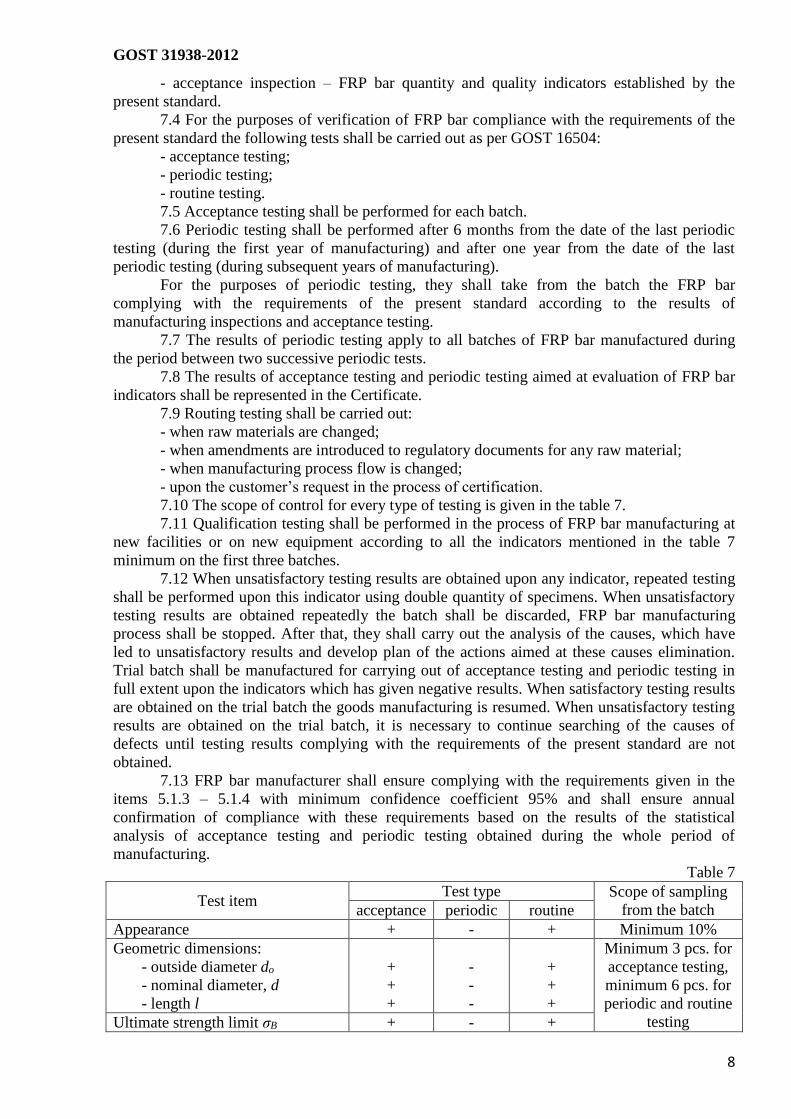
Table 7
Test item Test type Scope of sampling
from the batch acceptance periodic routine
Appearance + - + Minimum 10%
Geometric dimensions:
- outside diameter do
- nominal diameter, d
- length l
+
+
+
-
-
-
+
+
+
Minimum 3 pcs. for
acceptance testing,
minimum 6 pcs. for
periodic and routine
testing Ultimate strength limit σB + - +

GOST 31938-2012
9
Elastic modulus Et + - +
Minimum 3 pcs. for
acceptance testing,
minimum 6 pcs. for
periodic and routine
testing
Compressive strength σac - + +
Cross-shearing strength τsh - + +
Strength of adhesion to concrete τr - + +
Reduction of ultimate strength
limit after curing in alkaline
medium, ∆σR
- + +
Adhesion to concrete after curing
in alkaline medium τr
- + +
Ultimate service temperature - + +
7.14 When manufacturing process stability is evaluated, compliance of FRP bar
indicators with the required values is determined based on the results obtained for the period not
exceeding 6 months. Criteria of FRP bar indicators compliance with the required values for
manufacturing process stability evaluation are given in the table 8.
7.15 FRP bar compliance with the required indicators shall be determined by means of
the calculation of the number of testing results obtained for evaluation period which are outside
the limits of the required values, and by comparison of this number with the acceptance number.
7.16 FRP bar compliance with actually required value is confirmed when the number of
testing results outside the limits of the required values does not exceed the acceptance number.
Table 8
Number of tests Acceptance number
1-6 1
13-19 2
20-29 3
30-39 4
40-49 5
50-64 6
65-79 7
80-94 8
95-100 10
8 Control methods
8.1 FRP bar surface appearance and quality shall be inspected visually as for compliance
with the established requirements or reference specimen without using any special magnifying
devices.
8.2 Outside diameter, die-rolled section height, die-rolled section pitch of FRP bar shall
be checked using beam-compass as per GOST 166 and using micrometer as per GOST 6507.
8.3 FRP bar length shall be checked using ruler as per GOST 427, using measuring tape
as per GOST 7502 having nominal scale length 10, 20 m, third class of accuracy.
8.4 Nominal diameter shall be determined as per GOST 15139 as supplemented (see
Annex A).
8.5 Mechanical properties at axial tension shall be determined as per GOST 12004 as
amended and supplemented (see Annex B).
8.6 Compression strength shall be determined as per GOST 4651 as amended and
supplemented (see Annex C).
8.7 Cross-shearing strength shall be determined according to the Annex D.
8.8 Strength of adhesion to concrete shall be determined according to the Annex E.
8.9 Resistance to alkali medium of concrete shall be determined according to the Annex
F.

GOST 31938-2012
10
8.10 Ultimate service temperature shall be determined according to the Annex F.
8.11 Effective specific activity of natural radioactive nuclides of raw materials used for
FRP bar manufacturing shall be determined as per GOST 30108.
9 Shipping and storage
9.1 FRP bars shall be shipped in horizontal position in any vehicle according to the
shipping rules effective for the certain type of vehicle with adherence to the storage
requirements.
9.2 FRP bars shall be stored in horizontal position on a rack in unheated or heated
warehouses at the distance not less than 1 m from heating devices at the minimum height from
the floor of 100 mm.
9.3 During storage, shipping and handling one shall consider the measures preventing
mechanical damage of FRP bars, effects of ultraviolet radiation and moisture.
10. Manufacturer guarantees
10.1 The manufacturer guarantees FRP bars compliance with the requirements of the
present standard provided that customer considers requirements and regulations on storage,
shipping and usage.
10.2 Guarantee period for FRP bars storage – 24 months from the date of manufacturing.
10.3 Upon expiration of the guarantee storage period FRP bars could be used only after
its testing for absolute compliance with the requirements of the present standard.

GOST 31938-2012
11
Annex A
(reference)
Method for Determination of Nominal Diameter
A.1 General
The present method is based upon determination (based on the results of hydrostatic
weighing) of the volume of the specimen cut from the inspected item with the specified length
and subsequent calculation of nominal diameter.
A.2 Specimens
A.2.1 Test specimens are taken by the method of random selection from the inspected
batch of FRP bars. It is required that this process is documented in the sampling certificate
containing the following information:
- name of the manufacturing company;
- identification code;
- type of fiber and binding substance;
- date of manufacturing;
- batch number;
- quantity and dimensions of specimens;
- indicators to be inspected using the taken specimens;
- signature of the person responsible for sampling.
A.2.2 In the process of FRP bars specimens selection and preparation for testing it is
necessary to exclude deformation and heating, the effects of ultraviolet radiation and other
environmental impacts which can cause changes of the material properties.
A.2.3 Number of specimens taken for testing shall comply with the requirements of the
table 7.
A.2.4 Measured fragments used as testing specimens shall have the length l, mm,
determined by the formula:
l ≥ 10 lnp (A.1)
where lnp – is length of die-rolled section pitch, mm.
A.2.5 Before testing the test specimens shall be cured according to the requirements of
GOST 12423.
A.3 Equipment and materials
The following equipment and materials are used for the testing:
- analytical balances, minimum 2d accuracy class;
- vessel and fixing (clamps) for hydrostatic weighing to analytical balances;
- beam-compass as per GOST 166, maximum scale division – 0.1 mm.
A.4 Conduction of testing
A.4.1 Testing conditions shall comply with the section 3.15 of GOST 15150.
A.4.2 The length of every specimen shall be measured 3 times while rotating the
specimen by the angle of 120° after each measurement. The average value of three
measurements shall be rounded to 0.1 mm. The length of a specimen shall be measured with the
tolerance of not more than 0.1 mm.
A.4.3 The vessel for hydrostatic weighing shall be filled with distilled water, left at a
room temperature for 2 hours.
A.4.4 The clamps without specimen shall be immersed into the vessel filled with water,
the indications of the balances shall be zeroed or recorded.
A.4.5 The specimen shall be fixed in the clamps and the balances reading m1 shall be
recorded. Then the specimen together with the clamps shall be immersed into the water and
balances reading m2 shall be recorded.

GOST 31938-2012
12
A.5 Processing of the testing results
Nominal diameter d, mm, shall be calculated by the formula:
𝑑 = √4(𝑚1−𝑚2)
𝜋𝜌𝑙, (A.2)
where m1 – weight of a specimen in the air, mg;
m2 – weight of a specimen in the water, mg;
ρ – water density, mg/mm3 (taken as ρ = 1);
l – length of a specimen, mm.
The values of the evaluated characteristics and quantities used for intermediate
calculations shall be determined with the relative accuracy of not less than 0.01 (1%).
Statistical processing of the testing results shall be performed according to the
requirements of GOST 8.207.
A.6 Test report
Test report shall contain the following:
- the information about the specimens given in the sampling certificate;
- name of the company conducting the testing;
- date of testing;
- the information about testing conditions;
- the values of the measured parameters for every specimen;
- the values of the determined characteristics for every specimen obtained in the process
of the testing results processing;
- the average values, standard deviation of the determined characteristics and the results
of testing results statistical processing;
- the information about the specialists who have conducted testing and their signatures.

GOST 31938-2012
13
Annex B
(reference)
Axial tension test method
B.1 General
The present method establishes requirements for axial tension testing of FRP bar for the
purposes of determination of the following properties:
- strength limit;
- elastic modulus;
- percentage elongation;
The method establishes the following requirements for axial tension testing of FRP bar:
- specimen destruction shall occur within the limits of the operating zone;
- the part of a specimen located between testing sleeves used for specimen clutching
within the grips of testing machine is considered as the operating zone;
- the effect of shearing load and radial tensile load occurring in the intermediate zone
from the testing sleeve to the bar on the process of specimen destruction shall not be taken into
consideration.
B.2 Specimens
B.2.1 Test specimens are taken by the method of random selection from the inspected
batch of FRP bar. It is required that this process is documented in the sampling certificate
containing the following information:
- name of the manufacturing company;
- identification code;
- type of fiber and binding substance;
- date of manufacturing;
- batch number;
- quantity and dimensions of specimens;
- indicators to be inspected using the taken specimens;
- signature of the person responsible for sampling.
In the process of selection of FRP bar specimens and preparation for testing it is
necessary to exclude deformation and heating, the effects of ultraviolet radiation and other
environmental impacts which can cause changes of the material properties.
Number of specimens taken for testing shall comply with the requirements of the table 7.
B.2.2 The length of testing sleeves shall be determined based on the conditions ensuring
specimen rupturing within the length of the operating zone without slipping in testing sleeves.
B.2.3 Length of test specimen s is determined by the length of the operating zone and the
length of two testing sleeves.
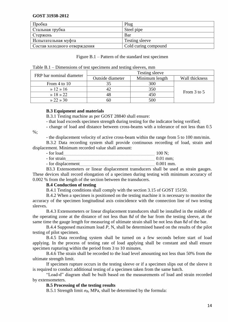
The recommended structure and dimensions of testing sleeve are given in the figure B.1
and the table B.1.
The length of the operating zone shall be minimum 40d of the bar.
B.2.4 It is permitted to use shorter specimens provided that the rupture occurs within the
length of the operating zone without slipping in testing sleeves.
B.2.5 Before testing test specimens shall be cured according to the requirements of GOST
12423.
GOST 31938-2012
14
Пробка Plug
Стальная трубка Steel pipe
Стержень Bar
Испытательная муфта Testing sleeve
Состав холодного отверждения Cold curing compound
Figure B.1 – Pattern of the standard test specimen
Table B.1 – Dimensions of test specimens and testing sleeves, mm
FRP bar nominal diameter Testing sleeve
Outside diameter Minimum length Wall thickness
From 4 to 10 35 300
From 3 to 5 » 12 » 16 42 350
» 18 » 22 48 450
» 22 » 30 60 500
B.3 Equipment and materials
B.3.1 Testing machine as per GOST 28840 shall ensure:
- that load exceeds specimen strength during testing for the indicator being verified;
- change of load and distance between cross-beams with a tolerance of not less than 0.5
%;
- the displacement velocity of active cross-beam within the range from 5 to 100 mm/min.
B.3.2 Data recording system shall provide continuous recording of load, strain and
displacement. Minimum recorded value shall amount:
- for load 100 N;
- for strain 0.01 mm;
- for displacement 0.001 mm.
B3.3 Extensometers or linear displacement transducers shall be used as strain gauges.
These devices shall record elongation of a specimen during testing with minimum accuracy of
0.002 % from the length of the section between the transducers.
B.4 Conduction of testing
B.4.1 Testing conditions shall comply with the section 3.15 of GOST 15150.
B.4.2 When a specimen is positioned on the testing machine it is necessary to monitor the
accuracy of the specimen longitudinal axis coincidence with the connection line of two testing
sleeves.
B.4.3 Extensometers or linear displacement transducers shall be installed in the middle of
the operating zone at the distance of not less than 8d of the bar from the testing sleeve, at the
same time the gauge length for measuring of ultimate strain shall be not less than 8d of the bar.
B.4.4 Supposed maximum load P, N, shall be determined based on the results of the pilot
testing of pilot specimen.
B.4.5 Data recording system shall be turned on a few seconds before start of load
applying. In the process of testing rate of load applying shall be constant and shall ensure
specimen rupturing within the period from 3 to 10 minutes.
B.4.6 The strain shall be recorded to the load level amounting not less than 50% from the
ultimate strength limit.
If specimen rupture occurs in the testing sleeve or if a specimen slips out of the sleeve it
is required to conduct additional testing of a specimen taken from the same batch.
“Load-d” diagram shall be built based on the measurements of load and strain recorded
by extensometers.
B.5 Processing of the testing results
B.5.1 Strength limit σB, MPa, shall be determined by the formula:

GOST 31938-2012
15
𝜎𝐵 =𝑃
𝐴, (B.1)
where P – rupture load, N;
A – cross-section area of the bar A = πd2/4, mm2.
B.5.2 The value of initial tangent modulus of elasticity Ef, MPa, is calculated as a ratio of
load increment during tension within the range from 0.23P to 0.5P and strains by the formula:
𝐸𝑓 =𝑃1−𝑃2
(𝜀1−𝜀2)𝐴, (B.2)
where P1 – load amounting (50 ± 2) % of the rupture load, N;
P2 – load amounting (20 ± 2) % of the rupture load, N;
ε1 – strain corresponding to the load P1;
ε2 – strain corresponding to the load P2.
B.5.3 Relative elongation under rupture load εε, mm/mm, is calculated by the formula:
𝜀𝜀 = 𝑃
𝐸𝑙𝐴, (B.3)
The values of the evaluated characteristics and quantities shall be determined with the
accuracy of up to 0.001.
Statistical processing of the testing results shall be performed according to the
requirements of GOST 8.207.
B.6 Test report
Test report shall contain the following:
- the information about the specimens given in the sampling certificate;
- name of the company conducting the testing;
- date of testing;
- the information about testing conditions;
- geometric characteristics of each specimen;
- the values of the measured characteristics for every specimen;
- the values of the determined characteristics for every specimen obtained in the process
of the testing results processing;
- the average values, standard deviation of the determined characteristics and the results
of testing results statistical processing;
- “load-strain” diagram for every specimen;
- the information about the specialists who have conducted testing and their signatures.

GOST 31938-2012
16
Annex C
(reference)
Compression test method
C.1 General
The present method establishes requirements for compression testing of FRP bars for the
purposes of determination of compression strength.
The method is based on specimen rupturing by application of axial compression load.
The method considers main provisions of GOST 4651 as amended and supplemented:
- rupture of pilot specimen shall occur within the operating zone;
- the part of a specimen located between testing sleeves used is considered as the
operating zone;
- the effect of shearing load and radial tensile load occurring in the intermediate zone
from the testing sleeve to the bar on the process of specimen destruction shall not be taken into
consideration.
C.2 Specimens
C.2.1 Test specimens are taken by the method of random selection from the inspected
batch of FRP bars. It is required that this process is documented in the sampling certificate
containing the following information:
- name of the manufacturing company;
- identification code;
- type of fiber and binding substance;
- date of manufacturing;
- batch number;
- quantity and dimensions of specimens;
- indicators to be inspected using the taken specimens;
- signature of the person responsible for sampling.
In the process of FRP bar specimens selection and preparation for testing it is necessary
to exclude deformation and heating, the effects of ultraviolet radiation and other environmental
impacts which can cause changes of the material properties.
Number of specimens taken for testing shall comply with the requirements of the table 7.
C.2.2 Test specimen (see figure C.1) consists of the section of the bar at the ends of
which testing sleeves are mounted on glue line.
1- the section of the bar; 2 – testing sleeve
Figure C.1 – Schematic diagram of test specimen
C.2.3 Total length of a specimen is determined by bush construction.
C.2.4 Length of the bar operating zone located between bushes shall amount 6d.
C.2.5 Before testing the specimens shall be cured according to the requirements of GOST
12423.
GOST 31938-2012
17
C.3 Equipment and materials
C.3.1 Testing machine as per GOST 28840 shall ensure:
- that load exceeds specimen strength during testing for the indicator being verified;
- change of load and distance between cross-beams with a tolerance of not less than 0.5
%;
- the displacement velocity of active cross-beam within the range from 5 to 100 mm/min.
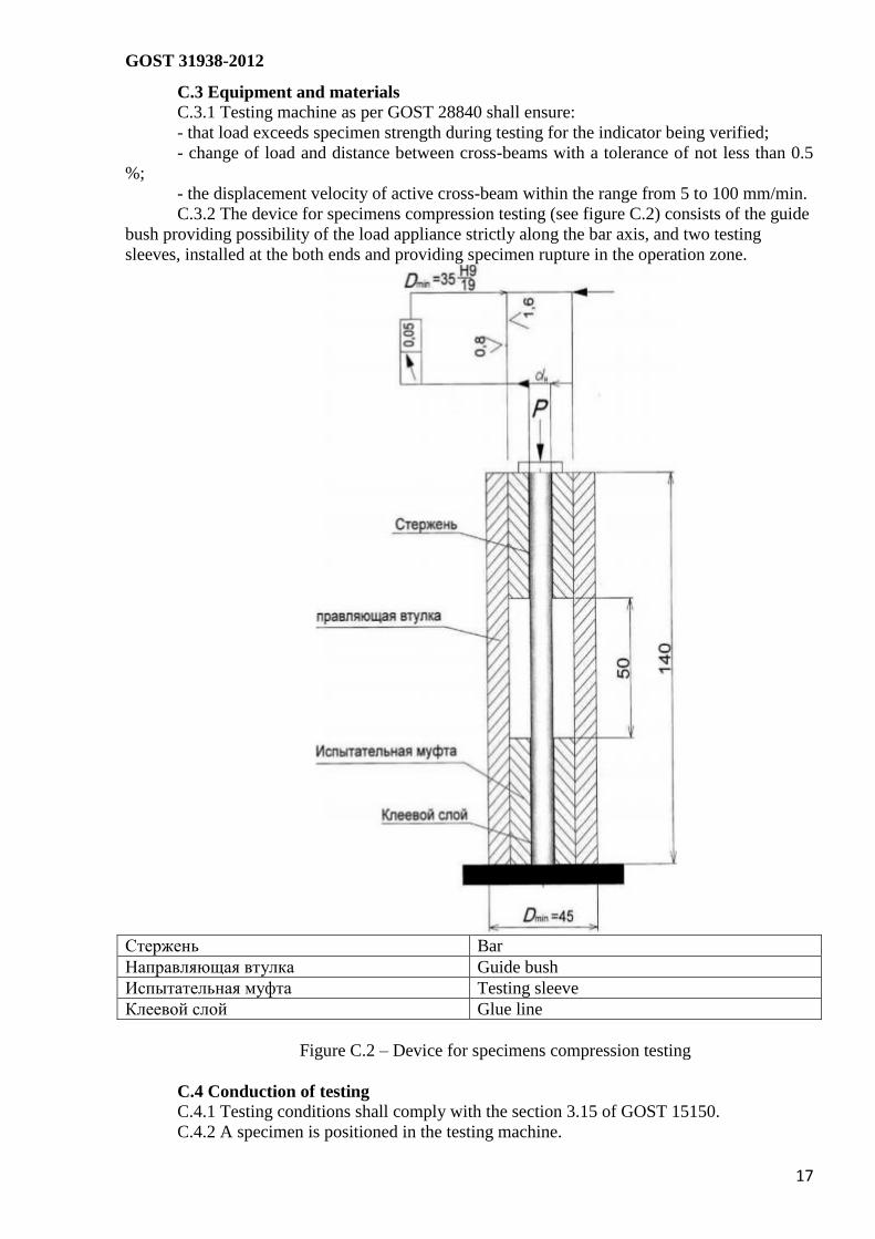
C.3.2 The device for specimens compression testing (see figure C.2) consists of the guide
bush providing possibility of the load appliance strictly along the bar axis, and two testing
sleeves, installed at the both ends and providing specimen rupture in the operation zone.
Стержень Bar
Направляющая втулка Guide bush
Испытательная муфта Testing sleeve
Клеевой слой Glue line
Figure C.2 – Device for specimens compression testing
C.4 Conduction of testing
C.4.1 Testing conditions shall comply with the section 3.15 of GOST 15150.
C.4.2 A specimen is positioned in the testing machine.
GOST 31938-2012
18
C.4.3 The measuring system is turned on and the drive of the testing machine is switched
to the test mode. The recommended velocity value lays within the range from 5 to 15 mm/min.
The load shall be applied gradually; a specimen shall not be subjected to impacts.
C.4.4. Applying of load shall be continued until a specimen is ruptured. If a specimen
rupture occurs outside the limits of the operating zone it is required to conduct additional testing
of a specimen taken from the same batch.
C.4.5 Rupture load is determined with the accuracy of up to 0.001.
C.5 Processing of the testing results
C.5.1 Compressive strength σBC, MPa, shall be determined by the formula:
𝜎𝐵𝐶 =4𝑃
𝜋𝑑2, (C.1)
where P – rupture load, N;
d – nominal diameter, mm.
The values of the evaluated characteristics and quantities shall be determined with the
accuracy of up to 0.001.
Statistical processing of the testing results shall be performed according to the
requirements of GOST 8.207.
C.6 Test report
Test report shall contain the following:
- the information about the specimens given in the sampling certificate;
- name of the company conducting the testing;
- date of testing;
- the information about testing conditions;
- geometric characteristics of each specimen;
- test results;
- the values of the measured characteristics for every specimen;
- the values of the determined characteristics for every specimen obtained in the process
of the testing results processing;
- the average values, standard deviation of the determined characteristics and the results
of testing results statistical processing;
- the information about the specialists who have conducted testing and their signatures.

GOST 31938-2012
19
Annex D
(reference)
Transverse shear strength test method
D.1 General provisions
The present test method sets the requirements to testing FRP bars on the basis of
determining the value of maximal shear strength at shearing of the bar in the transverse direction
with regard to the fibers.
The method is based on loading the specimen with the shearing strength by means of direct
applying of the double shear
D.2 Test specimens
D.2.1 Test specimens are selected randomly from the controlled lot of FRP with mandatory
formalization of the selection procedure by issuing the specimens sampling protocol, which
should include:
name of the manufacturing company;
designation marks;
type of the fiber and bonding substance used;
date of production;
lot number;
number and size of specimens;
parameters that should be tested on selected specimens;
signature of the person responsible for the sampling procedure
While sampling and preparation of specimens there should be avoided any and all
deformation, heating, exposure to ultraviolet light and other environmental effects that might
cause changes to material properties.
The number of specimens selected for testing must comply with the requirements set out in
Table 7.
D.2.2 A selected for testing specimen represents a bar, the length of which is determined
based on the testing machine design, but not less than 250 mm irrespective of the specimen
diameter
D.2.3 Before performance of testing the specimens should be cured according to the
requirements set out in the provisions of GOST 12423.
D.3 Testing equipment and materials
D.3.1 According to the provisions of GOST 28840 the testing machine should provide for:
loading capacity in excess of the tensile capacity of the specimen when performing
testing for the controlled parameter;
measurements of loading capacity and the distance between the transverse shears
with the error of not more than 0.5%.
the active transverse shear displacement speed should be within the rate of 5 to 100
mm per minute.
D.3.2 The testing machine used for performance of tests must consist of the specimen
holder with a longitudinal V-shaped groove (see Figure D.1), a rectangular-shaped groove for
fixture of the upper and lower blades with the V-shaped grooves or the holes to run through (see
Figure D.2) for mounting of the specimens calibrated in compliance with their diameter.
D.3.3 The total sum of two gaps between one upper blade and two lower blades should be
not less than 0.25 mm.

GOST 31938-2012
20
1 — Test specimen holder; 2 —
upper blade;
3 — lower blades; 4 — specimen
Figure D.1 — Apparatus for
testing the specimens for
transverse shear strength.
1 — specimen; 2 — upper blade; 3 — lower blades.
Figure D.2 — Installation diagram of the test apparatus with the holes to run through
D.4 Performance of tests
D.4.1 The testing conditions should comply with the requirements of subparagraph 3.15
GOST 15150.
D.4.2 The specimen should be inserted into the center of the test apparatus and installed in
the testing machine.
D.4.3 The surface of upper blade should contact with the loading device of the testing
machine. No gap is admissible.
D.4.4 The measuring appliance and the drive of the testing machine are switched on into
the testing mode. The loading rate shall be such that the shearing stress amounts from 5 to 15
mm per minute. The loading should be applied uniformly without subjecting the specimen to
shocks.
D.4.5 The specimen should be cut by blade edges in two planes simultaneously converging
along the faces perpendicular to its axis.
D.4.6 To decrease friction of the blade edges their surfaces are to be grinded, polished or
covered with a thin lubrication coating.
D.4.7 The loading should be applied until the failure of the specimen.
D 4 8 The shear failure load should be determined with the accuracy of up to 0.001.
D.4.9 While performing the test vertical displacements of the bar are measured with the
b) Element by element a) Assembled

GOST 31938-2012
21
accuracy of up to 0.01 mm with the help of the electronic meter used for measuring the
displacement of the hydraulic press slabs.
D.5 Processing of test results
The maximally allowable shear strength τsh, МPa is calculated according to the formula:
(D.1)
where Р is the shear failure load, N;
А is the nominal cross-sectional area of the specimen. А = πd2/4. mm2
Statistical processing of the test results shall be performed compliant to the requirements of
GOST 8.207.
D.6 Test protocol
The test protocol shall include the following items:
information about the specimens, as provided in the specimens sampling protocol;
name of the testing facility that performed the testing;
date of performance of testing;
information about the conditions for performance of testing;
geometrical characteristics of each specimen;
results of the tests;
values of measured characteristics for each of the tested specimen:
values of the characteristics determined for each of the specimens, which were obtained
at processing of the results of the tests;
average values of the determined characteristics and the results of statistical processing
of the obtained results;
type and manner of shear failure for each specimen;
personal data of the experts engaged in performing the testing and their signatures.

GOST 31938-2012
22
Annex E
(reference)
Test of limit bond strength to concrete
E.1 General provisions
The present test method sets the requirements to performance of testing for bond strength
between the FRP bars and concrete by means of axial pull-out of the reinforcement bar from the
concrete cube or for bending tensile capacity of the bar.
The method is based on determining the values of displacement tensile stress along the
boundary of FRP bonding with the concrete realized at the maximum load applied and obtained
at the maximum load resulting in pull-out elongation of the specimen before its load failure,
irrespective of the place where the specimen failure occurs (whether along the bar length or
along the boundary of the bar bonding with the concrete).
E.2 Test specimens
E.2.1 Test specimens are selected randomly from the controlled lot of FRP bars with
mandatory formalization of the selection procedure by issuing the specimens sampling protocol,
which should include:
name of the manufacturing company;
designation marks;
type of the fiber and bonding substance used;
date of production;
lot number;
number and size of specimens;
parameters that should be tested on selected specimens;
signature of the person responsible for the sampling procedure
While sampling and preparation of specimens there should be avoided any and all
deformation, heating, exposure to ultraviolet light and other environmental effects that might
cause changes to material properties.
The number of specimens selected for testing must comply with the requirements set out in
Table 7.
E.2.2 The specimens for testing the bond strength by means of axial pull-out of the bar
from the concrete cube consist of concrete cubes, in the centers of which there are vertically
installed bar-shaped FRP bars with the testing sleeve perpendicular or in parallel to the direction
of concrete layer (see Figure E.1). the dimensions of concrete cubes depending upon the FRP
bar diameters are provided in Table E.1.
Total length of the specimen to be tested is determined by the following factors:
conditions of installation and fitting into the concrete cube;
conditions of mounting of the specimen in the testing machine;
design of the testing sleeve.
E.2.3 Part of the FRP bar bonded into concrete should be sheathed by a polyvinylchloride
T a b l e E.1 — Dimensions of the specimens, mm
Nominal diameter of the FRP
bar Size of the concrete cube edge
FRP bar-to-concrete bonded
length
≤10 100
5 d 12 to 18 150
20 to 30 200
GOST 31938-2012
23
insert or tube.
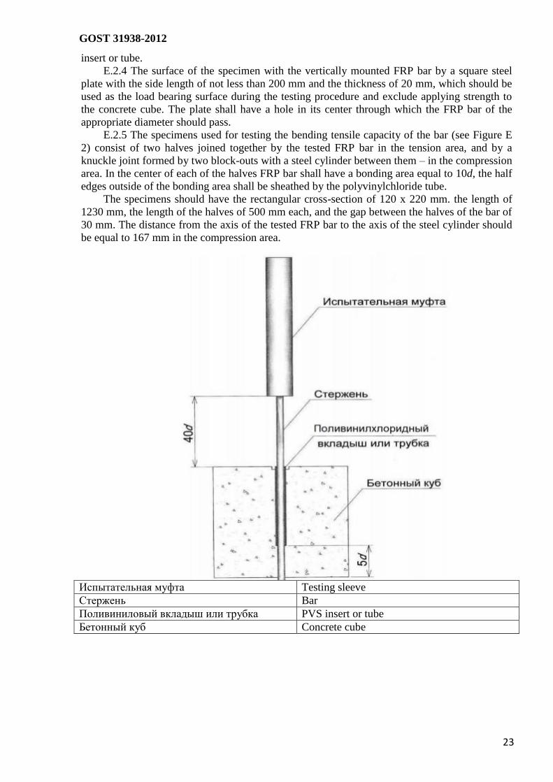
E.2.4 The surface of the specimen with the vertically mounted FRP bar by a square steel
plate with the side length of not less than 200 mm and the thickness of 20 mm, which should be
used as the load bearing surface during the testing procedure and exclude applying strength to
the concrete cube. The plate shall have a hole in its center through which the FRP bar of the
appropriate diameter should pass.
E.2.5 The specimens used for testing the bending tensile capacity of the bar (see Figure E
2) consist of two halves joined together by the tested FRP bar in the tension area, and by a
knuckle joint formed by two block-outs with a steel cylinder between them – in the compression
area. In the center of each of the halves FRP bar shall have a bonding area equal to 10d, the half
edges outside of the bonding area shall be sheathed by the polyvinylchloride tube.
The specimens should have the rectangular cross-section of 120 x 220 mm. the length of
1230 mm, the length of the halves of 500 mm each, and the gap between the halves of the bar of
30 mm. The distance from the axis of the tested FRP bar to the axis of the steel cylinder should
be equal to 167 mm in the compression area.
Испытательная муфта Testing sleeve
Стержень Bar
Поливиниловый вкладыш или трубка PVS insert or tube
Бетонный куб Concrete cube

GOST 31938-2012
24
Figure E.1 - Installation diagram of FRP bar mounting in the concrete cube
1 - bar; 2 - polyvinylchloride insert or tube; 3 – steel cylinder
Figure E.2 - Installation diagram of FRP bar mounting in the concrete while testing the
bending tensile capacity of the bar
E.2.6 It is recommended the following mode of making up the concrete in the form:
the concrete mix shall be placed in four layers of approximately equal thickness
whereas each layer should be poked 25 times by a metal bar having the diameter
of 16 mm;
after puddling of the upper layer the surface should be smoothed and cleaned from
moisture evaporations, including the bonding section of the vertically mounted
FRP bar.
E.2.7 The requirements set to the concrete quality shall be the following:
maximum dimensions of coarse aggregates 20 to 25 mm;
mobility of concrete mix, grade P3;
concrete compressive strength, grade B25.
E.2.8 The compressive strength of the concrete shall be determined on the basis of the
concrete cubes having the edge size of 100 mm whereas at least three specimens are tested.
Removal of forms from the test shall be performed not earlier than 24 hours after their
manufacturing. The specimens shall be stored under normal conditions. The age of the test
specimens used for testing shall be 28 days.
E.2.9 Before performance of testing the specimens should be cured according to the
requirements set out in GOST 12423.
E.3 Testing equipment and materials
E.3.1 According to the provisions of GOST 28840 the testing machine should provide for:
loading capacity in excess of the tensile capacity of the specimen when performing
testing for the controlled parameter;
measurements of loading capacity and the distance between the transverse shears
with the error of not more than 0.5%;
the active transverse shear displacement speed should be within the rate of 5 to 100
mm per minute.
E.3.2 To measure slippage of the FRP bar from the concrete there should be applied strain
gauges, linear variable differential transformers, and analog or digital display sensors with the
accuracy of up to 0.01 mm (the devices for measuring slippage).
E.3.3 To prepare the specimens there should be required:
metal forms for manufacturing concrete cubes and the loading plates having holes
for mounting the bar-shaped FRP bar of the appropriate diameter. The loading
plates have to be waterproof and easily removable without causing any damage to

GOST 31938-2012
25
the FRP bars;
anchorage sections in compliance with the requirements of Table 5.1 Annex B.
E.4 Performance of tests
E 4.1 The testing conditions should comply with the requirements of subparagraph 3.15
GOST 15150.
E.4.2 The specimen used for performance of bond strength test by means of axial pull-out
of the reinforcement bar from the concrete cube shall be mounted in a manner that the loading
plate of the concrete cube, from which the free end of the FRP bar shall protrude, should
contact via the soft gasket with the moving transverse shear of the testing machine (see Figure
E.3).
1 – slippage measuring device at the free end of the bar; 2 – specimen; 3 – loading
plate; 4 – soft gasket; 5 – moving transverse shear of the testing machine; 6 - fixed transverse
shear of the testing machine; 7 – anchorage section.
Figure E.3 — Installation diagram of mounting the specimen at axial pull-out from the concrete
cube
E.4.3 The load-transmission device shall rest on the support transmitting the load to the
force-measuring device of the testing machine.
E.4.4 The protruding bar shall pass through the node of the load-transmission device and
the loading plate while the testing sleeve shall be mounted via the fixed transverse shear or in
the holders of the testing machine.
E.4.5 The device for measuring slippage shall be installed on the free end of the FRP bar.
E.4.6 the distance between the upper surface of the fixed transverse shear or the holders of
the testing machine to the surface where the device for measuring slippage is installed, shall be
measured with the accuracy of up to ±0.01 mm.
E.4 7 When the bar has undergone a failure or has slipped out of the testing sleeve before it
slips form the concrete, or the applied load is significantly reduced due cracking of the concrete,
then the measurement data are rejected and the tests are repeated using an additional specimen
from the same lot.
E.4.8 If splitting of the concrete occurs as the result of testing, then it is required to increase
the size of the edge of the concrete tubes or apply for beam test.
E.4.9 Testing for bending tensile capacity of the bar shall be performed according to the
method shown in Figure E.4. The slippage measuring device shall be installed on both end faces
of the beam at the end of the bar.
GOST 31938-2012
26
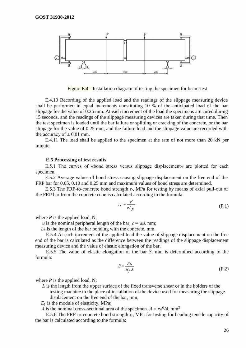
Figure E.4 - Installation diagram of testing the specimen for beam-test
E.4.10 Recording of the applied load and the readings of the slippage measuring device
shall be performed in equal increments constituting 10 % of the anticipated load of the bar
slippage for the value of 0.25 mm. At each increment of the load the specimens are cured during
15 seconds, and the readings of the slippage measuring devices are taken during that time. Then
the test specimen is loaded until the bar failure or splitting or cracking of the concrete, or the bar
slippage for the value of 0.25 mm, and the failure load and the slippage value are recorded with
the accuracy of ± 0.01 mm.
E.4.11 The load shall be applied to the specimen at the rate of not more than 20 kN per
minute.
E.5 Processing of test results
E.5.1 The curves of «bond stress versus slippage displacement» are plotted for each
specimen.
E.5.2 Average values of bond stress causing slippage displacement on the free end of the
FRP bar for 0.05, 0.10 and 0.25 mm and maximum values of bond stress are determined.
E.5.3 The FRP-to-concrete bond strength τr, МPa for testing by means of axial pull-out of
the FRP bar from the concrete cube is calculated according to the formula:
(F.1)
where P is the applied load, N;
u is the nominal peripheral length of the bar, с = πd, mm;
Lb is the length of the bar bonding with the concrete, mm.
E.5.4 At each increment of the applied load the value of slippage displacement on the free
end of the bar is calculated as the difference between the readings of the slippage displacement
measuring device and the value of elastic elongation of the bar.
E.5.5 The value of elastic elongation of the bar S, mm is determined according to the
formula:
(F.2)
where P is the applied load, N;
L is the length from the upper surface of the fixed transverse shear or in the holders of the
testing machine to the place of installation of the device used for measuring the slippage
displacement on the free end of the bar, mm;
Ef is the module of elasticity, MPa;
А is the nominal cross-sectional area of the specimen. А = πd2/4. mm2
E.5.6 The FRP-to-concrete bond strength τr, МPa for testing for bending tensile capacity of
the bar is calculated according to the formula:

GOST 31938-2012
27
(F.3)
E.5.7 The axial force in the bar N, N in the middle of the beam is calculated according to
the formula:
(F.4)
where M is the total momentum of the cross-section, which divides the beam in two halves, N •
mm;
z is the arm of the internal pair of the cross-section dividing the beam in two halves, it is
equal to the distance between the bar axis and the axis of the steel cylinder in the compression
area, mm.
E.5.6 Test protocol
The test protocol shall include the following items:
information about the specimens, as provided in the specimens sampling protocol;
name of the testing facility that performed the testing;
date of performance of testing;
information about the conditions for performance of testing;
geometrical characteristics of each specimen;
information about the quality of the concrete: composition and mobility of the concrete
mix, compressive strength of concrete tests pieces at the age of 28 days;
information about the bars, as provided in the specimens sampling protocol – ultimate
bond strength during pull-out testing and the value of the module of elasticity,
dimensions of the specimens, bonded length of the bars mounting into the concrete;
values of measured characteristics for each of the tested specimen:
values of the characteristics determined for each of the specimens, which were obtained
at processing of the results of the tests;
average values of the determined characteristics and the results of statistical processing
of the obtained results;
type of load failure, curves of «bond stress versus slippage displacement» for each
specimen;
personal data of the experts engaged in performing the testing and their signatures.

GOST 31938-2012
28
Annex F
(reference)
Alkali resistance accelerated test method
F.1 General provisions
The present test method sets the requirements to estimation of alkali resistance of the FRP
bars by means of their immersion into the alkaline aqueous solution under the conditions of the
effect of the alkaline environment on the FRP bars with subsequent performance of tensile
testing and bond stress testing.
F.2 Scope of the method
The method envisages performance of testing under two testing procedures:
Procedure А is the procedure, under which the specimens are immersed into the
alkaline aqueous solution with subsequent straining of them until the complete failure occurs.
The controlled parameters include – the pH level, the temperature of the alkaline aqueous
solution, and the immersion time;
Procedure B is the procedure, under which the specimens, one end of which is fitted
with the anchorage section for fitting the specimen in the testing machine, while the other is
immersed into the alkaline aqueous solution and bonded with the concrete with subsequent
pulling it out of the concrete. The controlled parameters include – the pH level, the temperature
of the alkaline aqueous solution, and the immersion time.
F.3 Test specimens
F.3.1 Test specimens are selected randomly from the controlled lot of FRP bars with
mandatory formalization of the selection procedure by issuing the specimens sampling protocol,
which should include:
name of the manufacturing company;
designation marks;
type of the fiber and bonding substance used;
date of production;
lot number;
number and size of specimens;
parameters that should be tested on selected specimens;
signature of the person responsible for the sampling procedure
While sampling and preparation of specimens there should be avoided any and all
deformation, heating, exposure to ultraviolet light and other environmental effects that might
cause changes to material properties.
The number of specimens selected for testing must comply with the requirements set out in
Table 7.
F.3.2 Total length of the specimens subject to testing under Procedure А shall comply with
B.2.3 Annex B.
F.3.3 The specimens subject to testing under Procedure B shall comply with E.2.2 Annex E
F.3.4 The concrete mix shall be placed in accordance with the instructions set out in E 2.6
Annex E
F.3.5 The requirements set of the quality of concrete shall be in compliance with the
provisions of E.2.7, E.2.8 Annex E
F.3.6 In order to prevent infiltration of the alkaline aqueous solution into the body of the
bar, the end faces of the specimens subject to testing under Procedures А and B should be
coated with a thin layer of epoxy resin.
F.3.7 The specimens shall be cured before performance of testing in accordance with the
requirements set out in GOST 12423.
GOST 31938-2012
29
F.4 Testing equipment and materials F.4.1 According to the provisions of GOST 28840 the testing machine should provide for:
loading capacity in excess of the tensile capacity of the specimen when performing
testing for the controlled parameter;
measurements of loading capacity and the distance between the transverse shears
with the error of not more than 0.5%;
the active transverse shear displacement speed should be within the rate of 5 to 100
mm per minute.
F.4.2 The alkaline aqueous solution shall simulate the pore solution found in the concrete
and be of the following composition: 8.0 g of NaOH and 22.4 g КОН in 1 l of deionized water.
F.4.3 The value of pH of the alkaline aqueous solution shall be within the limits of 12.6 to
13. Before and after the test the alkaline aqueous solution should be kept in a closed container to
avoid its interaction with the СO2 contained in the ambient air and evaporation.
F.4.4 The anchorage sections shall comply with the requirements set out in Table B.1
Annex B.
F.5 Performance of tests
F 5.1 The sequence of performance of testing under Procedure А shall be the following:
- before immersion into the alkaline aqueous solution the specimen should be dried till
the constant mass m0 at the temperature of (100 ±2) °С.
- the specimens shall be immersed into the alkaline aqueous solution with the constant
temperature of (60 ± 3) °С for 30 days, at that, it is allowed to immerse into the alkaline aqueous
solution not the entire specimen but only its tested part between the testing sleeves;
- after immersion the specimen should be removed from the alkaline aqueous solution,
rinsed in deionized water, dried at the temperature of (100 ±2) °С within not less than 4 hours,
and then weighed (m1).
the specimens shall be installed in the testing sleeves and tested for strength limit
until complete failure pursuant to Annex B.
F.5.2 The sequence of performance of testing under Procedure B shall be the following:
the specimens shall be immersed into the alkaline aqueous solution with the
constant temperature of (60 ± 3) °С for 30 days, at that, it is allowed to immerse into the
alkaline aqueous solution not the entire specimen but only its tested part bonded into the
concrete;
after immersion the specimen should be removed from the alkaline aqueous
solution;
one end of the specimen shall be installed in the testing sleeve designed for its
fixing in the testing machine, the other end of the specimen (immersed in the alkaline solution)
shall be mounted in the concrete in accordance with the provisions of E.2.3, E.2.4 Annex E;
after 28 days of the concrete curing the specimen shall be installed in the testing
machine under the procedure as shown in Figure E.3:
the testing shall be performed in accordance with the provisions of E.4.2, E.4.3,
E.4.4, E.4.6, E 4.8, and E.4.10 Annex E in order to determine the ultimate bond strength with
the concrete.
F.5.3 While performing tests under Procedures A and B the pH value of the alkaline
aqueous solution shall be measured before and after the tests.
F.5.4 External appearance of the specimen (color, variation of the surface and geometrical
dimensions) should be examined before and after immersion into the alkaline aqueous solution
in compliance with 8.1 and 8.8
F.5.5 When performing the strain capacity test the load shall be applied to the specimen at
the rate of 5 to 15 mm/min.
F.5.6 When performing the pull-out test for bond strength the load shall be applied to the

GOST 31938-2012
30
specimen at the rate of not more than 20 N/min or 1 mm/min.
F.5.7 the material properties of bars shall be assessed only on the basis of the specimens
undergoing failure in the test section. In the cases when tensile failure or slippage takes place at
the testing sleeve, the data are disregarded and additional tests should be carried out with the
specimens representing the same lot of production.
F.6 Processing of test results
F.6.1 Changing of the FRP bar mass Δm, % is calculated according to the formula:
(F.1)
where m1 is the mass of the specimen after immersion into the alkaline
aqueous solution, g; т0 is the mass of the specimen before immersion, g.
F.6 2 The ultimate strength limit is calculated according to the formula (B.1).
F 6.3 Variation of the ultimate strength limit Δσ, % is calculated according to the formula:
(F.2)
where σ1 is the ultimate strength limit after immersion, MPa;
σ2 is the ultimate strength limit before immersion, MPa.
F.6.4 The ultimate FRP bar-to-concrete bond strength is calculated according to the
formula (E.3) Annex E.
F.6.5 Variation of the ultimate FRP bar -to-concrete bond strength Δτr, % is
calculated according to the formula:
(F.3)
where τr1 is the ultimate FRP bar-to-concrete bond strength after immersion, MPa;
τr is the ultimate FRP bar-to-concrete bond strength before immersion, MPa.
Statistical processing of the test results shall be performed compliant to the requirements of
GOST 8.207.
F.7 Test protocol
The test protocol shall include the following items:
information about the specimens, as provided in the specimens sampling protocol;
name of the testing facility that performed the testing;
date of performance of testing;
information about the conditions for performance of testing;
geometrical characteristics of each specimen;
information about the conditions for performance of testing (composition of the alkaline
solution, the value of pH, temperature, and the immersion period and time);
values of measured characteristics for each of the tested specimen (change of mass, the
ultimate strength limit, and the module of elasticity);
values of the characteristics determined for each of the specimens, which were obtained
at processing of the results of the tests;
average values of the determined characteristics and the results of statistical processing
of the obtained results;
type of load failure, curves of «load versus deformation» for each specimen;
personal data of the experts engaged in performing the testing and their signatures.
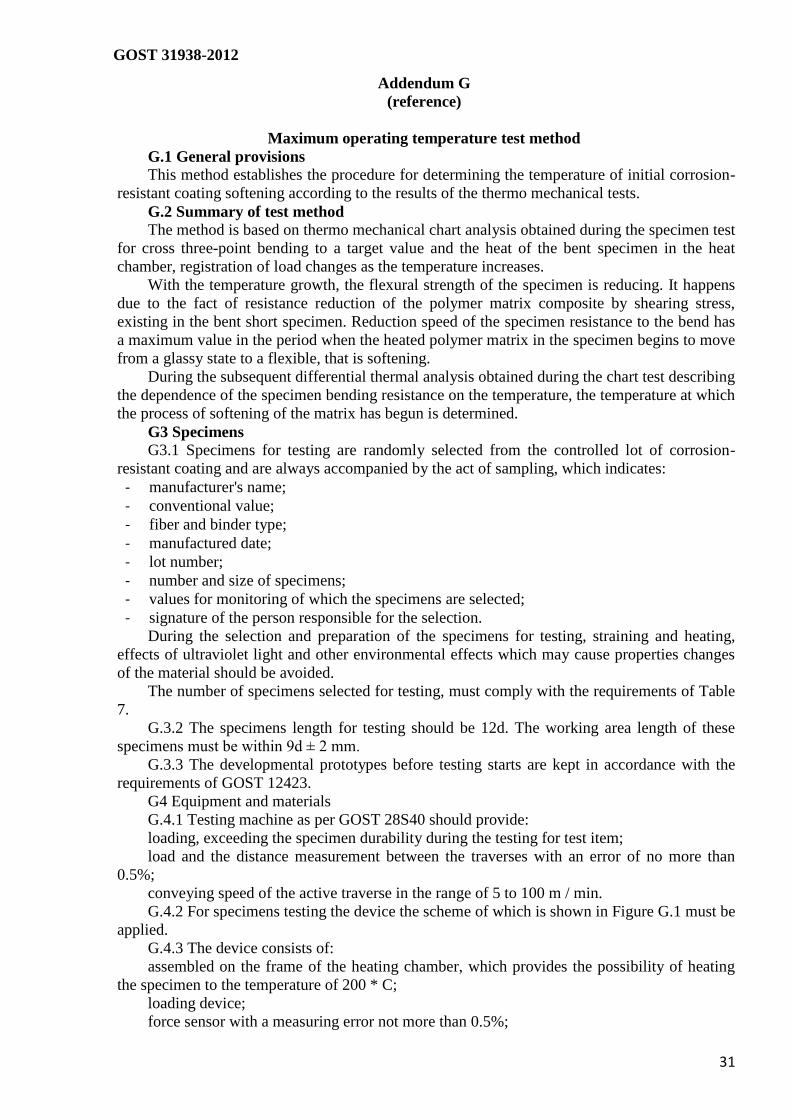
GOST 31938-2012
31
Addendum G
(reference)
Maximum operating temperature test method
G.1 General provisions
This method establishes the procedure for determining the temperature of initial corrosion-
resistant coating softening according to the results of the thermo mechanical tests.
G.2 Summary of test method
The method is based on thermo mechanical chart analysis obtained during the specimen test
for cross three-point bending to a target value and the heat of the bent specimen in the heat
chamber, registration of load changes as the temperature increases.
With the temperature growth, the flexural strength of the specimen is reducing. It happens
due to the fact of resistance reduction of the polymer matrix composite by shearing stress,
existing in the bent short specimen. Reduction speed of the specimen resistance to the bend has
a maximum value in the period when the heated polymer matrix in the specimen begins to move
from a glassy state to a flexible, that is softening.
During the subsequent differential thermal analysis obtained during the chart test describing
the dependence of the specimen bending resistance on the temperature, the temperature at which
the process of softening of the matrix has begun is determined.
G3 Specimens
G3.1 Specimens for testing are randomly selected from the controlled lot of corrosion-
resistant coating and are always accompanied by the act of sampling, which indicates:
- manufacturer's name;
- conventional value;
- fiber and binder type;
- manufactured date;
- lot number;
- number and size of specimens;
- values for monitoring of which the specimens are selected;
- signature of the person responsible for the selection.
During the selection and preparation of the specimens for testing, straining and heating,
effects of ultraviolet light and other environmental effects which may cause properties changes
of the material should be avoided.
The number of specimens selected for testing, must comply with the requirements of Table
7.
G.3.2 The specimens length for testing should be 12d. The working area length of these
specimens must be within 9d ± 2 mm.
G.3.3 The developmental prototypes before testing starts are kept in accordance with the
requirements of GOST 12423.
G4 Equipment and materials
G.4.1 Testing machine as per GOST 28S40 should provide:
loading, exceeding the specimen durability during the testing for test item;
load and the distance measurement between the traverses with an error of no more than
0.5%;
conveying speed of the active traverse in the range of 5 to 100 m / min.
G.4.2 For specimens testing the device the scheme of which is shown in Figure G.1 must be
applied.
G.4.3 The device consists of:
assembled on the frame of the heating chamber, which provides the possibility of heating
the specimen to the temperature of 200 * C;
loading device;
force sensor with a measuring error not more than 0.5%;
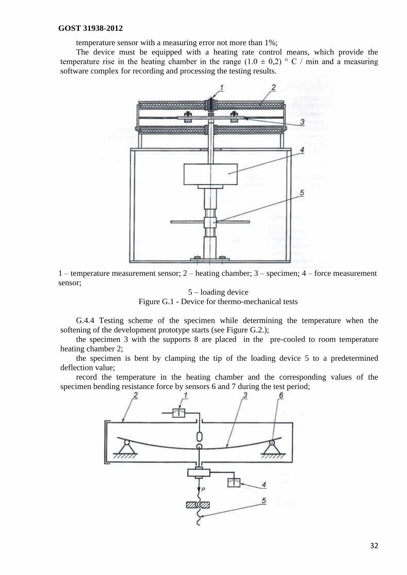
GOST 31938-2012
32
temperature sensor with a measuring error not more than 1%;
The device must be equipped with a heating rate control means, which provide the
temperature rise in the heating chamber in the range (1.0 ± 0,2) ° C / min and a measuring
software complex for recording and processing the testing results.
1 – temperature measurement sensor; 2 – heating chamber; 3 – specimen; 4 – force measurement
sensor;
5 – loading device
Figure G.1 - Device for thermo-mechanical tests
G.4.4 Testing scheme of the specimen while determining the temperature when the
softening of the development prototype starts (see Figure G.2.);
the specimen 3 with the supports 8 are placed in the pre-cooled to room temperature
heating chamber 2;
the specimen is bent by clamping the tip of the loading device 5 to a predetermined
deflection value;
record the temperature in the heating chamber and the corresponding values of the
specimen bending resistance force by sensors 6 and 7 during the test period;
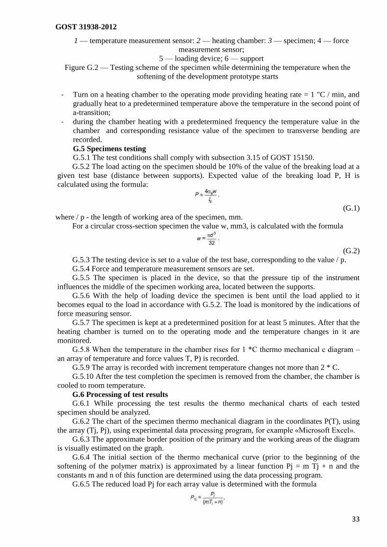
GOST 31938-2012
33
1 — temperature measurement sensor: 2 — heating chamber: 3 — specimen; 4 — force
measurement sensor;
5 — loading device; 6 — support
Figure G.2 — Testing scheme of the specimen while determining the temperature when the
softening of the development prototype starts
- Turn on a heating chamber to the operating mode providing heating rate = 1 "C / min, and
gradually heat to a predetermined temperature above the temperature in the second point of
а-transition;
- during the chamber heating with a predetermined frequency the temperature value in the
chamber and corresponding resistance value of the specimen to transverse bending are
recorded.
G.5 Specimens testing
G.5.1 The test conditions shall comply with subsection 3.15 of GOST 15150.
G.5.2 The load acting on the specimen should be 10% of the value of the breaking load at a
given test base (distance between supports). Expected value of the breaking load P, H is
calculated using the formula:
(G.1)
where / p - the length of working area of the specimen, mm.
For a circular cross-section specimen the value w, mm3, is calculated with the formula
(G.2)
G.5.3 The testing device is set to a value of the test base, corresponding to the value / p.
G.5.4 Force and temperature measurement sensors are set.
G.5.5 The specimen is placed in the device, so that the pressure tip of the instrument
influences the middle of the specimen working area, located between the supports.
G.5.6 With the help of loading device the specimen is bent until the load applied to it
becomes equal to the load in accordance with G.5.2. The load is monitored by the indications of
force measuring sensor.
G.5.7 The specimen is kept at a predetermined position for at least 5 minutes. After that the
heating chamber is turned on to the operating mode and the temperature changes in it are
monitored.
G.5.8 When the temperature in the chamber rises for 1 *С thermo mechanical c diagram –
an array of temperature and force values T, P) is recorded.
G.5.9 The array is recorded with increment temperature changes not more than 2 * C.
G.5.10 After the test completion the specimen is removed from the chamber, the chamber is
cooled to room temperature.
G.6 Processing of test results
G.6.1 While processing the test results the thermo mechanical charts of each tested
specimen should be analyzed.
G.6.2 The chart of the specimen thermo mechanical diagram in the coordinates P(T), using
the array (Tj, Pj), using experimental data processing program, for example «Microsoft Excel».
G.6.3 The approximate border position of the primary and the working areas of the diagram
is visually estimated on the graph.
G.6.4 The initial section of the thermo mechanical curve (prior to the beginning of the
softening of the polymer matrix) is approximated by a linear function Pj = m Tj + n and the
constants m and n of this function are determined using the data processing program.
G.6.5 The reduced load Pj for each array value is determined with the formula

GOST 31938-2012
34
(G.3)
where Ti - temperature value in the array, , *С
Pi - force value in the array, H;
m and n – the values of the empirical constants of the straight line approximating initial section
of the load depending Pi with which the specimen resists to bending from the temperature Ti, in
the heating chamber.
G.6.6 The new data array (Ti, Pi) is built, the working area of which is approximated by
the formula sigmoid
(G.4)
where a. b, c, d - empirical constants of the sigmoid approximating the experimental data.
The function with number 8011of the software product «Table Curve Windows v 1.10» is
recommended for determining constants.
G.6.7 The values of the first and second temperature derivative of the mathematical
function [P (T)] is determined with the help of the software product «Table Curve Windows v.
110», by which the dependence working area of the given load values Pi applied to the
specimen during the test, by temperature values Ti in a heating chamber is approximated.
G.6.8 The temperature value whereby the second derivative of the function [Pi (T)] has a
minimum value is taken as the temperature Ti for which the numerical values of the function Pi,
(T) and its first derivative CP / kT is found on the thermo mechanical diagrams.
G.6.9 The temperature value whereby the second derivative of the function [Pi (T)] has the
maximum value is taken as the temperature Ti.
G.6.10 The temperature value whereby the first derivative of the function [Pi (T)] has the
maximum value is taken as the temperature Тс, °С.
G.6.11 According to the obtained values of T0 and Tc G1ts the correctness of the
preliminary borders assessment of the initial and the working area of the thermo mechanical
curve diagram and decide on the need for re-treatment chart is evaluated and decide whether the
repeated diagram processing is needed.
G.6.12 The limiting operating temperature T3."C is calculated with the formula
(G.5)
(G.6)
G.7 Test Accuracy
G.7.1 Temperature in the test chamber shall be measured with an error of not more than 2
“С.
G.7.2 Specimen resistance to cross bending shall be measured with an error of not more
than 0.5% of the maximum value of the force obtained during testing.
G.7.3 The values that determine the characteristics, constants and other variables that are
used in intermediate calculations should be determined with an accuracy of up to 0.001.
G.8 Test report
The test report shall include;
- Information about the specimens that are listed in the selection act of specimens;
- test date;
- information about the conditions under which the tests were done;
- tests results;

GOST 31938-2012
35
- the values of measured characteristics for each test specimen;
- the values of the determined characteristics of each specimen obtained while the
processing the test results;
- average values of the determined characteristics and results of statistical processing of the
received data;
- initial thermo mechanical test diagram of each specimen;
- the reduced thermo mechanical test diagram of each specimen;
- dependence diagram of the first derivative reduced load to the temperature for each
specimen;
- dependence diagram of the second derivative reduced load to the temperature for each
specimen;
- information about the test technicians, and their signatures.

GOST 31938-2012
36
Addendum H
(reference)
Passport form
PASSPORT №
Manufacturer:
(name, address, telephone, fax
)________________________________________________________
Date of manufacture
________________________________________________________________
Shipping date
_____________________________________________________________________
Conventional value of corrosion-resistant coating
__________________________________________
Lot № ___________
Lot weight, kg
____________________________________________________________________
Total lot length ____________ m
Number of products in the packaging ________ pieces
Regulated parameters of the quality
_____________________________________________________________________________
____
The certificate availability (if certified)
Other regulated parameters of the quality (if necessary)
Issue date «__»______20__year
Head of laboratory ________________/____________________/
(signature)
QC Department ________________/____________________/
(signature)
Bundler _______________________/
(signature)

GOST 31938-2012
37
Bibliography
[1] SanPin 2.1 2 729—99 Polymer and polymer-containing building materials, products and
structures.
[2] SP 2 2.2 1327—2003 Hygienic safety requirements
[3] SanPin 2.2.3.1385—2003 Hygienic requirements for the organization of technological
processes, production equipment and working tools
[4] SP 1.1.1058—2001 Organization and carrying out production control over compliance with
sanitary regulations and the implementation of sanitary and anti-epidemic (preventive) measures
[5] SP 1.1.2193—2007 Organization and carrying out production control over compliance with
sanitary regulations and the implementation of sanitary and anti-epidemic (preventive). Changes
and additions 1 to SP 1.1.1058—2001
[6] GN 1.1.6.1338—2003 Maximum permissible concentration (MPC) of pollutants in the
ambient air of populated areas
[7] SanPin 2.6.1.2523—2009 Radiation Safety Standards (NRB-99/2009)

GOST 31938-2012
38
UDC 621.002.3: 006.354 ISS 91.080.40 H13 NEQ
Keywords: polymer composite reinforcement, acceptance rules, control methods, test methods

GOST 31938-2012
39
Editor O.I. Kashtanova
Technical editor V.N.Prusakova
Proofreader M.V. Buchnaya
Computer-aided makeup O.D. Cherepkovoy
Put for typing 24.12.2013. Signed for print 16.01.2014. Format 60x84 1/5 Arial headset.
Conv.print.sh. 4,65
published sheets 3,72. Edition 118 examples. Order 44.
Published and printed in FSUE «STANDARTINFORM», 4 Granatniy lane, Moscow, 123995
www.gostinfo.ru [email protected]