gotthard base tunnel sedrun section mastering squeezing ... · pdf fileexperience of...
TRANSCRIPT

Underground Space Use: Analysis of the Past and Lessons for the Future – Erdem & Solak (eds)© 2005 Taylor & Francis Group, London, ISBN 04 1537 452 9
277
1 FUNDAMENTAL CONSIDERATIONSREGARDING PLANNING ANDIMPLEMENTATION
Since the route of the Gotthard Base Tunnel (GBT)was decided, it has been known that in the Sedrun sec-tion two constructional difficult zones – the TavetschIntermediate Massif (TIM) (North) and the UrserenGarvera Zone (UGZ) – must be cut through. In bothzones, squeezing rock conditions are expected to beencountered.The main questions during design and constructionare:
1. With what type of ground conditions are we con-fronted?
2. What phenomena could hinder the successful con-struction of a tunnel?
3. What are the constructional measures to overcomethese phenomena, so that a tunnel can be con-structed safely at an acceptable cost?
In each phase of the project, answers to these ques-tions have been, and are, found by application of theprocedure shown simplified in Fig. 2.
The main project steps are:
– Geological exploration– Description of the rock mass based on the geolog-
ical exploration– Assessment of the rock mass with regard to exca-
vation of the underground cavity– Determination of the cross section– Determination of the rock support– Determination of the method of excavation– Determination of the requirement for construc-
tional aids– Definition of the radial and longitudinal proce-
dures (construction sequence)
Gotthard Base Tunnel Sedrun section mastering squeezing rock zones
Heinz EhrbarAlpTransit Gotthard Ltd., Lucerne, Switzerland
ABSTRACT: Since more than three years the main tunnel of the Gotthard Base Tunnel is under construction.In the central section of Sedrun large zones with squeezing rock are predicted. The project takes the high forcesand the necessary deformations into account. For the rock support steel ribs are the main elements. Special onsite tests were carried out to check the effectiveness of the chosen rock support.
Figure 1. Gotthard Base Tunnel, geological risk zones. Figure 2. General planning procedure.
2 CONSTRUCTIONAL FOUNDATION
2.1 Geological exploration
The owner AlpTransit Gotthard Ltd. (ATG) alreadydecided at an early stage to explore the geologicallydifficult zones with extensive test-bore campaigns andother investigations. The following test-bore campaignswere conducted:
1991: Diagonal bore SB 1 L � 838 m1991: Diagonal bore SB 2 L � 543 m1993: Diagonal bore SB 3.1 L � 780 m1997: Diagonal bore SB 4.1 L � 1750 m1997/98: Diagonal bore SB 3.2 L � 1716 m
The Urseren Garvera zone was not explored withtest bores. However, since this tectonic unit had beentraversed during construction of the headrace tunnelfor the Vorderrhein hydropower scheme, and whenbuilding the Gotthard road tunnel, sufficient knowl-edge and experience was available.
During the construction phase, horizontal testbores are made in both of the single-track tunnels, tothe north as well as to the south. Depending on therock conditions, the test bores are either percussion orcore bores. The length of the bores varies between36 m for the percussion bores and from 150 m up to400 m (in the region of the Nalps dam) fore the corebores. Depending on the evaluation of the potentialhazard of water ingress, the test bores are protectedwith preventers.
2.2 Description of the rock situation
The test bores to the north have indicated that the1.1 km long Tavetsch Intermediate Massif North con-sists to approximately 70% of soft, kakiritic rocks dis-playing ductile fracture behaviour. Approximately 30%of the rock is hard and displays brittle facture behav-ior. Hard and soft rocks alternate in narrow verticallayers. Where the material resembles loose rock, it issaturated with water.
2.3 Assessment of the rock mass
The assessment of the rock serves to forecast thecomposition and behavior of the rock which will beencountered when constructing the underground cav-ity. This evaluation, as well as an evaluation of therock in relation to water and gas, was made project-specifically based on known hazard scenarios.
In the Tavetsch Intermediate Massif (North) aswell as in the Urseren Garvera zone, the predominanthazard is the phenomenon of squeezing rock.
In view of the high overburden of 900 m and more,as well as the fact that the rock is saturated with water,the squeezing conditions are classified as extreme.
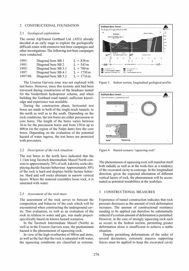
The phenomenon of squeezing rock will manifest itselfboth radially as well as at the work-face as a tendencyof the excavated cavity to converge. In the longitudinaldirection, given the expected alternation of differentvertical layers of rock, the phenomenon will be accen-tuated as potential instabilities at the workface.
3 CONSTRUCTIONAL MEASURES
Experience of tunnel construction indicates that rockpressure decreases as the amount of rock deformationincreases. The amount of constructional resistanceneeding to be applied can therefore be substantiallyreduced if a certain amount of deformation is permitted.However, in the case of strongly squeezing rock suchas occurs in the Sedrun section, permitting greaterdeformation alone is insufficient to achieve a stablesituation.
Despite permitting deformations of the order ofseveral decimeters, extremely massive supportingforces must be applied to keep the excavated cavity
278
Figure 3. Sedrun section, longitudinal geological profile.
Figure 4. Hazard scenario “squeezing rock”.

open. Without permitting deformations, it would betechnically practically impossible to create the forcesneeded to keep the excavated cross section open.
3.1 Design of the cross section
The specifications for the high-speed railway line inthe GBT stipulate a minimum free air cross sectionFair of 41.0 m2. The high forces on the constructionexpected from the true rock pressure demand a struc-turally optimal form. For this reason, through-out theentire Sedrun section, the only cross section whichcan be used for the single-track tunnel is a circle,whereas in sections with favorable geological condi-tions the base of the tunnel is made flat to assist con-struction operations.
3.2 Mining engineering methods of support
Considerations based on the principles of rock mechan-ics resulted in a concept being sought which wouldfulfill the conditions specific to the Sedrun situation,
i.e. a concept which would allow a high degree ofdeformation but also provide a high level of outwardresistance when completed.
In their search, both owner and project engineersendeavored to find a solution based on proven tech-nology. The technique applied in German coal minesof using deformable steel inserts with Toussaint-Heintzmann (TH) sections fulfilled the specifiedrequirements.
After excavation of the cavity, two steel ring insertseach consisting of eight segments are assembled toform two concentric rings. The joins can slide overeach other to a predefined limited extent, whichallows the overall system to deform radially. Whenfully compressed, the system attains a maximumload-bearing pressure of approx. 1.8 MPa.
The insertion process is shown idealized and sym-metrical in Fig. 5. However, this idealized situationwill rarely be achieved in practice. The GBT projectallows a degree of tolerance for uneven deformation,which in the mining industry leads to the term ‘swim-ming inserts’.
279
Figure 5. Experience of tunnelling in squeezing rock.
Figure 6. Normal profiles.
Figure 7. Principle of steel rib support.
Figure 8. Supporting concept in squeezing rock.
In the most extreme case, the steel rings areinserted practically ‘shoulder to shoulder’. In addi-tion to the steel inserts, the system is also reinforcedwith a systematic radial anchoring using up to 25 m ofanchor per tunnel meter. The tunnel face is alsoanchored to a similar extent.
After the steel rings have been inserted, they arepermanently concreted into place with shotcrete.
The overall supporting concept in the Sedrun sec-tion is modular, so as to allow optimal deployment ofthe associated machinery.
3.3 Constructional aids
Constructional aids are measures which enable driv-ing under exceptional conditions by improving therock (increased strength, rigidity, reduced permeabil-ity, etc.) and assuring the stability of the tunnel face.
In the main contract for the construction of theSedrun Section, the following measures are foreseen:
– long advance drainage;– grouting (individual grouting, grouting shields,
grouting bodies);– reinforcement of tunnel-face anchors and lances;– re-profiling if necessary.
3.4 Construction procedure
The procedures for creating the profile are based onthe following considerations:
The exploratory bores which have been made inthe TIM (North), and the associated laboratory tests,indicate that in the TIM (North) an extreme amount ofsqueezing must be expected. Quick closure of the ringis therefore essential to keep the cross section open.For this reason, in the Sedrun section full-face excava-tion will always be used followed by immediate ring
closure. The procedure for closing the ring will be asfollows:
– After each advance, the steel rings are inserted(2 � TH 44, minimum distance 33 cm).
– 12 m long radial anchors are inserted to form ananchoring system.
– 18 m long tunnel-face anchors are inserted afterevery 6 m of advance.
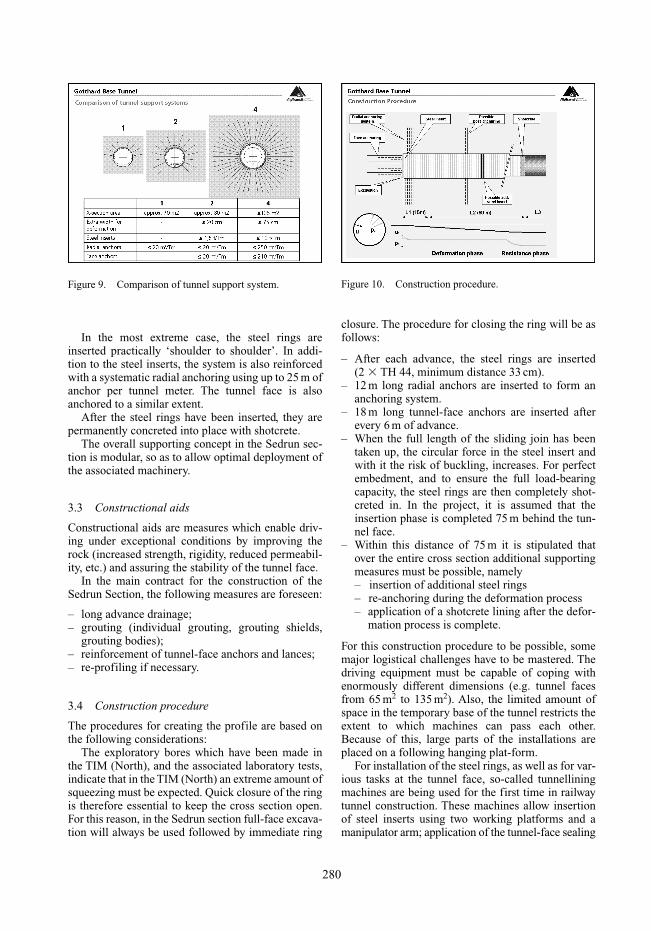
– When the full length of the sliding join has beentaken up, the circular force in the steel insert andwith it the risk of buckling, increases. For perfectembedment, and to ensure the full load-bearingcapacity, the steel rings are then completely shot-creted in. In the project, it is assumed that theinsertion phase is completed 75 m behind the tun-nel face.
– Within this distance of 75 m it is stipulated thatover the entire cross section additional supportingmeasures must be possible, namely– insertion of additional steel rings– re-anchoring during the deformation process– application of a shotcrete lining after the defor-
mation process is complete.
For this construction procedure to be possible, somemajor logistical challenges have to be mastered. Thedriving equipment must be capable of coping withenormously different dimensions (e.g. tunnel facesfrom 65 m2 to 135 m2). Also, the limited amount ofspace in the temporary base of the tunnel restricts theextent to which machines can pass each other.Because of this, large parts of the installations areplaced on a following hanging plat-form.
For installation of the steel rings, as well as for var-ious tasks at the tunnel face, so-called tunnelliningmachines are being used for the first time in railwaytunnel construction. These machines allow insertionof steel inserts using two working platforms and amanipulator arm; application of the tunnel-face sealing
280
Figure 9. Comparison of tunnel support system. Figure 10. Construction procedure.
from the work platform by means of spray nozzles;cutting the tunnel-face anchors to length withhydraulic pincers.
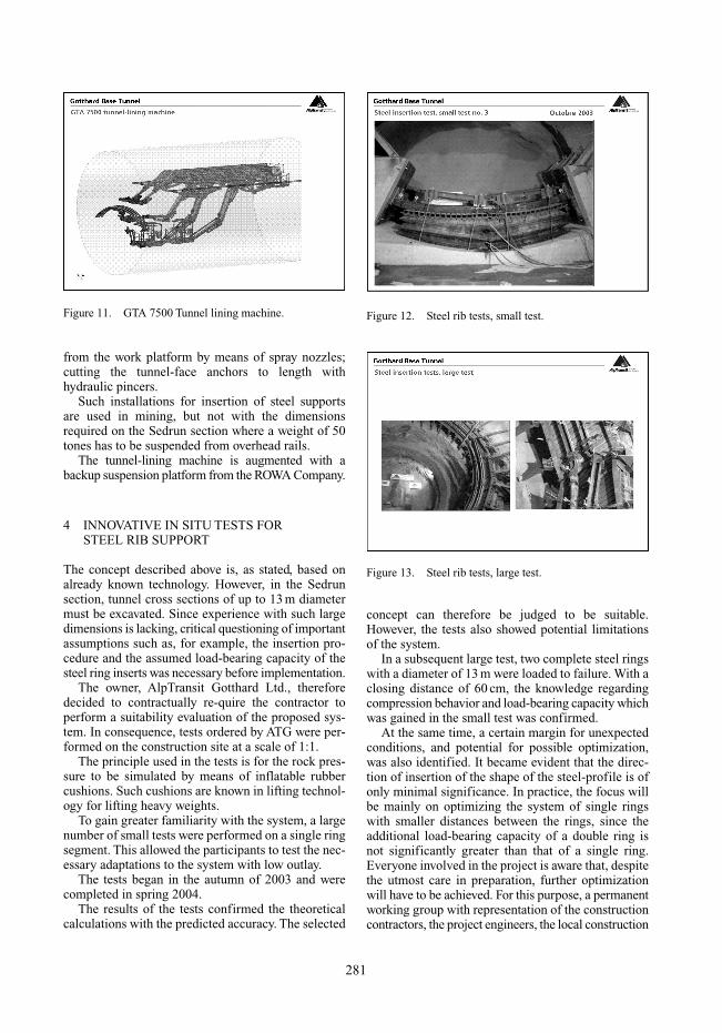
Such installations for insertion of steel supportsare used in mining, but not with the dimensionsrequired on the Sedrun section where a weight of 50tones has to be suspended from overhead rails.
The tunnel-lining machine is augmented with abackup suspension platform from the ROWA Company.
4 INNOVATIVE IN SITU TESTS FOR STEEL RIB SUPPORT
The concept described above is, as stated, based onalready known technology. However, in the Sedrunsection, tunnel cross sections of up to 13 m diametermust be excavated. Since experience with such largedimensions is lacking, critical questioning of importantassumptions such as, for example, the insertion pro-cedure and the assumed load-bearing capacity of thesteel ring inserts was necessary before implementation.
The owner, AlpTransit Gotthard Ltd., thereforedecided to contractually re-quire the contractor toperform a suitability evaluation of the proposed sys-tem. In consequence, tests ordered by ATG were per-formed on the construction site at a scale of 1:1.
The principle used in the tests is for the rock pres-sure to be simulated by means of inflatable rubbercushions. Such cushions are known in lifting technol-ogy for lifting heavy weights.
To gain greater familiarity with the system, a largenumber of small tests were performed on a single ringsegment. This allowed the participants to test the nec-essary adaptations to the system with low outlay.
The tests began in the autumn of 2003 and werecompleted in spring 2004.
The results of the tests confirmed the theoreticalcalculations with the predicted accuracy. The selected
concept can therefore be judged to be suitable.However, the tests also showed potential limitationsof the system.
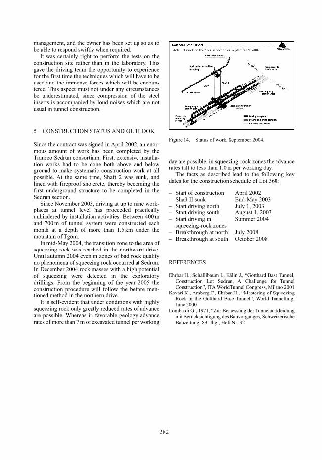
In a subsequent large test, two complete steel ringswith a diameter of 13 m were loaded to failure. With aclosing distance of 60 cm, the knowledge regardingcompression behavior and load-bearing capacity whichwas gained in the small test was confirmed.
At the same time, a certain margin for unexpectedconditions, and potential for possible optimization,was also identified. It became evident that the direc-tion of insertion of the shape of the steel-profile is ofonly minimal significance. In practice, the focus willbe mainly on optimizing the system of single ringswith smaller distances between the rings, since theadditional load-bearing capacity of a double ring isnot significantly greater than that of a single ring.Everyone involved in the project is aware that, despitethe utmost care in preparation, further optimizationwill have to be achieved. For this purpose, a permanentworking group with representation of the constructioncontractors, the project engineers, the local construction
281
Figure 11. GTA 7500 Tunnel lining machine. Figure 12. Steel rib tests, small test.
Figure 13. Steel rib tests, large test.
management, and the owner has been set up so as tobe able to respond swiftly when required.
It was certainly right to perform the tests on theconstruction site rather than in the laboratory. Thisgave the driving team the opportunity to experiencefor the first time the techniques which will have to beused and the immense forces which will be encoun-tered. This aspect must not under any circumstancesbe underestimated, since compression of the steelinserts is accompanied by loud noises which are notusual in tunnel construction.
5 CONSTRUCTION STATUS AND OUTLOOK
Since the contract was signed in April 2002, an enor-mous amount of work has been completed by theTransco Sedrun consortium. First, extensive installa-tion works had to be done both above and belowground to make systematic construction work at allpossible. At the same time, Shaft 2 was sunk, andlined with fireproof shotcrete, thereby becoming thefirst underground structure to be completed in theSedrun section.
Since November 2003, driving at up to nine work-places at tunnel level has proceeded practicallyunhindered by installation activities. Between 400 mand 700 m of tunnel system were constructed eachmonth at a depth of more than 1.5 km under themountain of Tgom.
In mid-May 2004, the transition zone to the area ofsqueezing rock was reached in the northward drive.Until autumn 2004 even in zones of bad rock qualityno phenomena of squeezing rock occurred at Sedrun.In December 2004 rock masses with a high potentialof squeezing were detected in the exploratorydrillings. From the beginning of the year 2005 theconstruction procedure will follow the before men-tioned method in the northern drive.
It is self-evident that under conditions with highlysqueezing rock only greatly reduced rates of advanceare possible. Whereas in favorable geology advancerates of more than 7 m of excavated tunnel per working
day are possible, in squeezing-rock zones the advancerates fall to less than 1.0 m per working day.
The facts as described lead to the following keydates for the construction schedule of Lot 360:
– Start of construction April 2002– Shaft II sunk End-May 2003– Start driving north July 1, 2003– Start driving south August 1, 2003– Start driving in Summer 2004
squeezing-rock zones– Breakthrough at north July 2008– Breakthrough at south October 2008
REFERENCES
Ehrbar H., Schällibaum I., Kälin J., “Gotthard Base Tunnel,Construction Lot Sedrun, A Challenge for TunnelConstruction”, ITA World Tunnel Congress, Milano 2001
Kovári K., Amberg F., Ehrbar H., “Mastering of SqueezingRock in the Gotthard Base Tunnel”, World Tunnelling,June 2000
Lombardi G., 1971, “Zur Bemessung der Tunnelauskleidungmit Berücksichtigung des Bauvorganges, SchweizerischeBauzeitung, 89. Jhg., Heft Nr. 32
282
Figure 14. Status of work, September 2004.