gp4000h series hardware manual · gp4000h series hardware manual safety information important...
TRANSCRIPT

GP4000H Series
Hardware Manual

The information provided in this documentation contains general descriptions and/or technical characteristics of the performance of the products contained herein. This documentation is not intended as a substitute for and is not to be used for determining suitability or reliability of these products for specific user applications. It is the duty of any such user or integrator to perform the appropriate and complete risk analysis, evaluation and testing of the products with respect to the relevant specific application or use thereof. Neither Pro-face nor any of its affiliates or subsidiaries shall be responsible or liable for misuse of the information that is contained herein. If you have any suggestions for improvements or amendments or have found errors in this publication, please notify us.
No part of this document may be reproduced in any form or by any means, electronic or mechanical, including photocopying, without express written permission of Pro-face.
All pertinent state, regional, and local safety regulations must be observed when installing and using this product. For reasons of safety and to help ensure compliance with documented system data, only the manufacturer should perform repairs to components.
When devices are used for applications with technical safety requirements, the relevant instructions must be followed.
Failure to use Pro-face software or approved software with our hardware products may result in injury, harm, or improper operating results.
Failure to observe this information can result in injury or equipment damage.
Copyright © 2016 Digital Electronics Corporation. All Rights Reserved.
2

GP4000H Series Hardware Manual
Table of Contents
Safety Information . . . . . . . . . . . . . . . . . . . . . . . . . . . . . 5About the Book. . . . . . . . . . . . . . . . . . . . . . . . . . . . . . . . 7
Chapter 1 Overview . . . . . . . . . . . . . . . . . . . . . . . . . . . . . . . . . . . . . 11Model Numbers . . . . . . . . . . . . . . . . . . . . . . . . . . . . . . . . . . . . . . . . . . 12Package Contents . . . . . . . . . . . . . . . . . . . . . . . . . . . . . . . . . . . . . . . . 13Certifications and Standards . . . . . . . . . . . . . . . . . . . . . . . . . . . . . . . . 14Federal Communication Commission Radio Frequency Interference Statement - For USA . . . . . . . . . . . . . . . . . . . . . . . . . . . . . . . . . . . . . . 16
Chapter 2 Device Connectivity . . . . . . . . . . . . . . . . . . . . . . . . . . . . 17System Design . . . . . . . . . . . . . . . . . . . . . . . . . . . . . . . . . . . . . . . . . . 18Accessories . . . . . . . . . . . . . . . . . . . . . . . . . . . . . . . . . . . . . . . . . . . . . 19
Chapter 3 Parts Identification and Functions . . . . . . . . . . . . . . . . 21Parts name and Functions. . . . . . . . . . . . . . . . . . . . . . . . . . . . . . . . . . 22LED Indications . . . . . . . . . . . . . . . . . . . . . . . . . . . . . . . . . . . . . . . . . . 24
Chapter 4 Specifications . . . . . . . . . . . . . . . . . . . . . . . . . . . . . . . . . 254.1 General Specifications. . . . . . . . . . . . . . . . . . . . . . . . . . . . . . . . . . . . . 26
Electrical Specifications. . . . . . . . . . . . . . . . . . . . . . . . . . . . . . . . . . . . 27Environmental Specifications . . . . . . . . . . . . . . . . . . . . . . . . . . . . . . . 28Structural Specifications . . . . . . . . . . . . . . . . . . . . . . . . . . . . . . . . . . . 29
4.2 Functional Specifications. . . . . . . . . . . . . . . . . . . . . . . . . . . . . . . . . . . 30Display Specifications . . . . . . . . . . . . . . . . . . . . . . . . . . . . . . . . . . . . . 31Memory, Clock, Touch Panel . . . . . . . . . . . . . . . . . . . . . . . . . . . . . . . 32
4.3 Interface Specifications . . . . . . . . . . . . . . . . . . . . . . . . . . . . . . . . . . . . 33Interface Specifications . . . . . . . . . . . . . . . . . . . . . . . . . . . . . . . . . . . . 34Interface Connection . . . . . . . . . . . . . . . . . . . . . . . . . . . . . . . . . . . . . . 36Connector for Direct-connect Cable . . . . . . . . . . . . . . . . . . . . . . . . . . 37Serial Interface . . . . . . . . . . . . . . . . . . . . . . . . . . . . . . . . . . . . . . . . . . 39Emergency Stop Switch / Stop Switch Output Interface . . . . . . . . . . . 413-Position Enable Switch Output Interface . . . . . . . . . . . . . . . . . . . . . 42Key Switch Output Interface . . . . . . . . . . . . . . . . . . . . . . . . . . . . . . . . 43DC Power Interface . . . . . . . . . . . . . . . . . . . . . . . . . . . . . . . . . . . . . . . 44Connecting the Power Supply . . . . . . . . . . . . . . . . . . . . . . . . . . . . . . . 45Grounding . . . . . . . . . . . . . . . . . . . . . . . . . . . . . . . . . . . . . . . . . . . . . . 47
Chapter 5 Dimensions . . . . . . . . . . . . . . . . . . . . . . . . . . . . . . . . . . . 49External Dimensions . . . . . . . . . . . . . . . . . . . . . . . . . . . . . . . . . . . . . . 50Dimensions with a Stop Switch Guard . . . . . . . . . . . . . . . . . . . . . . . . 52
Chapter 6 Installation. . . . . . . . . . . . . . . . . . . . . . . . . . . . . . . . . . . . 536.1 Fixing This Product . . . . . . . . . . . . . . . . . . . . . . . . . . . . . . . . . . . . . . . 54
Introduction . . . . . . . . . . . . . . . . . . . . . . . . . . . . . . . . . . . . . . . . . . . . . 55Hand Strap . . . . . . . . . . . . . . . . . . . . . . . . . . . . . . . . . . . . . . . . . . . . . 56Neck Strap. . . . . . . . . . . . . . . . . . . . . . . . . . . . . . . . . . . . . . . . . . . . . . 57Wall Hanging Adapter . . . . . . . . . . . . . . . . . . . . . . . . . . . . . . . . . . . . . 58
3
6.2 Direct-connect Cable Attaching/Removing . . . . . . . . . . . . . . . . . . . . . 59Introduction . . . . . . . . . . . . . . . . . . . . . . . . . . . . . . . . . . . . . . . . . . . . . 60Attaching the Cable . . . . . . . . . . . . . . . . . . . . . . . . . . . . . . . . . . . . . . . 61Removing the Cable. . . . . . . . . . . . . . . . . . . . . . . . . . . . . . . . . . . . . . . 62
6.3 Attaching the Stop Switch Guard . . . . . . . . . . . . . . . . . . . . . . . . . . . . . 63Introduction . . . . . . . . . . . . . . . . . . . . . . . . . . . . . . . . . . . . . . . . . . . . . 63
6.4 Replacing the Function Switch Sheet . . . . . . . . . . . . . . . . . . . . . . . . . 64Introduction . . . . . . . . . . . . . . . . . . . . . . . . . . . . . . . . . . . . . . . . . . . . . 64
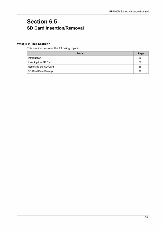
6.5 SD Card Insertion/Removal . . . . . . . . . . . . . . . . . . . . . . . . . . . . . . . . . 65Introduction . . . . . . . . . . . . . . . . . . . . . . . . . . . . . . . . . . . . . . . . . . . . . 66Inserting the SD Card. . . . . . . . . . . . . . . . . . . . . . . . . . . . . . . . . . . . . . 67Removing the SD Card . . . . . . . . . . . . . . . . . . . . . . . . . . . . . . . . . . . . 68SD Card Data backup . . . . . . . . . . . . . . . . . . . . . . . . . . . . . . . . . . . . . 70
Chapter 7 Maintenance . . . . . . . . . . . . . . . . . . . . . . . . . . . . . . . . . . 71Regular Cleaning . . . . . . . . . . . . . . . . . . . . . . . . . . . . . . . . . . . . . . . . . 72Periodic Check Points . . . . . . . . . . . . . . . . . . . . . . . . . . . . . . . . . . . . . 73Replacing the Backlight . . . . . . . . . . . . . . . . . . . . . . . . . . . . . . . . . . . . 74After-sales Service . . . . . . . . . . . . . . . . . . . . . . . . . . . . . . . . . . . . . . . . 75
4

GP4000H Series Hardware Manual
Safety Information
Important Information
NOTICE
Read these instructions carefully, and look at the equipment to become familiar with the device before trying to install, operate, or maintain it. The following special messages may appear throughout this documentation or on the equipment to warn of potential hazards or to call attention to information that clarifies or simplifies a procedure.
PLEASE NOTE
Electrical equipment should be installed, operated, serviced, and maintained only by qualified personnel. No responsibility is assumed by Pro-face for any consequences arising out of the use of this material.
A qualified person is one who has skills and knowledge related to the construction and operation of electrical equipment and its installation, and has received safety training to recognize and avoid the hazards involved.
5

6
GP4000H Series Hardware Manual
About the Book
At a Glance
Document Scope
This manual describes how to use this product.
Validity Note
This documentation is valid for this product.
The technical characteristics of the device(s) described in this manual also appear online at http://www.pro-face.com/.
The characteristics presented in this manual should be the same as those that appear online. In line with our policy of constant improvement we may revise content over time to improve clarity and accuracy. In the event that you see a difference between the manual and online information, use the online information as your reference.
Registered Trademarks
Microsoft and Windows are registered trademarks of Mircrosoft Corporation in the United States and/or other countries.
Product names used in this manual may be the registered trademarks owned by the respective proprietors.
Related Documents
You can download the manuals related to this product, such as the software manual, from our support site at http://www.pro-face.com/trans/en/manual/1001.html.
Product Related Information
If the equipment is used in a manner not specified by the manufacturer, the protection provided by the equipment may be impaired.
Critical alarm indicators and system functions require independent and redundant protection hardware and/or mechanical interlocks.
When you cycle power, wait at least 10 seconds after it has been turned off. If this product is restarted too quickly, it may not operate correctly.
DANGERHAZARD OF ELECTRIC SHOCK, EXPLOSION, OR ARC FLASH
Remove all power from the device before removing any covers or elements of the system, and prior to installing or removing any accessories, hardware, or cables.
Unplug the power cable from both this product and the power supply. Always use a properly rated voltage sensing device to confirm power is off. Replace and secure all covers or elements of the system before applying power to this
product. Use only the specified voltage when operating this product. This product is designed to use
24 Vdc. Always check whether your device is DC powered before applying power.
Failure to follow these instructions will result in death or serious injury.
7

In the event the screen cannot be properly read, for example, if the backlight is not functioning, it may be difficult or impossible to identify a function. Functions that may present a hazard if not immediately executed, such as a fuel shut-off, must be provided independently of this product. The machine’s control system design must take into account the possibility of the backlight no longer functioning and the operator being unable to control the machine or making mistakes in the control of the machine.
For additional information, refer to NEMA ICS 1.1 (latest edition), "Safety Guidelines for the Application, Installation, and Maintenance of Solid State Control" and to NEMA ICS 7.1 (latest edition), "Safety Standards for Construction and Guide for Selection, Installation and Operation of Adjustable-Speed Drive Systems" or their equivalent governing your particular location.
WARNINGLOSS OF CONTROL
The designer of any control scheme must consider the potential failure modes of control paths and, for certain critical control functions, provide a means to achieve a safe state during and after a path failure. Examples of critical control functions are emergency stop and overtravel stop, power outage and restart.
Separate or redundant control paths must be provided for critical control functions. System control paths may include communication links. Consideration must be given to the
implications of unanticipated transmission delays or failures of the link. Observe all accident prevention regulations and local safety guidelines. Each implementation of this product must be individually and thoroughly tested for proper
operation before being placed into service. The machine control system design must take into account the possibility that the emergency
stop switch may not work, control lines may be unable to function due to cut cable lines, or the backlight is no longer functioning, and therefore the operator is unable to control the machine or makes errors in the control of the machine.
Failure to follow these instructions can result in death, serious injury, or equipment damage.
WARNINGUNINTENDED EQUIPMENT OPERATION
The application of this product requires expertise in the design and programming of control systems. Only persons with such expertise should be allowed to program, install, alter, and apply this product.
Follow all local and national safety standards.
Failure to follow these instructions can result in death, serious injury, or equipment damage.
8

GP4000H Series Hardware Manual
The following characteristics are specific to the LCD panel and are considered normal behavior: LCD screen may show unevenness in the brightness of certain images or may appear different
when seen from outside the specified viewing angle. Extended shadows, or crosstalk may also appear on the sides of screen images.
LCD screen pixels may contain black and white colored spots and color display may seem to have changed.
When the same image is displayed on the screen for a long period, an afterimage may appear when the image is changed.
NOTE: Change the screen image periodically and try not to display the same image for a long period of time.
WARNINGUNINTENDED EQUIPMENT OPERATION
Do not use this product as the only means of control for critical system functions such as motor start/stop or power control.
Do not use this equipment as the only notification device for critical alarms, such as device overheating or overcurrent.
Use only the software provided with this product. If you use another software, please confirm the operation and safety before use.
Failure to follow these instructions can result in death, serious injury, or equipment damage.
CAUTIONRISK OF INJURY
Handle with care. Do not drop this product. Do not step on cables.
Failure to follow these instructions can result in injury or equipment damage.
CAUTIONSERIOUS EYE AND SKIN INJURY
The liquid in the LCD panel contains an irritant:
Avoid direct skin contact with the liquid. Wear gloves when you handle a broken or leaking unit. Do not use sharp objects or tools in the vicinity of the LCD panel. Handle the LCD panel carefully to prevent puncture, bursting, or cracking of the panel material. If the panel is damaged and any liquid comes in contact with your skin, immediately rinse the
area with running water for at least 15 minutes. If the liquid gets in your eyes, immediately rinse your eyes with running water for at least 15 minutes and consult a doctor.
Failure to follow these instructions can result in injury or equipment damage.
9

10
GP4000H Series Hardware Manual
Overview
KanpaiHandy_GP4000H 5/2016
GP4000H Series Hardware Manual
Overview
Chapter 1Overview
What Is in This Chapter?
This chapter contains the following topics:
Topic Page
Model Numbers 12
Package Contents 13
Certifications and Standards 14
Federal Communication Commission Radio Frequency Interference Statement - For USA 16
11

Overview
Model Numbers
*1 Includes models with additional alphanumeric characters at the end of the model number.
Model Number Configuration
The following describes the configuration of model numbers.
Global Code
A global code is assigned to every Pro-face product as a universal model number. For more information on product models and their matching global codes, please refer to the following URL.
http://www.pro-face.com/trans/en/manual/1003.html
Series Model name Model number*1
GP4000 Series GP4000H Series GP-4311HT PFXGP4311HTAD
PFXGP4311HTADER
PFXGP4311HTADERK
PFXGP4311HTADEYK
PFXGP4311HTADEGK
Digit Position
1 2 3 4 5 6 7 8 9 10 11 12 13
P F X (model) (series) (size) (resolution) (type) (LCD) (touch panel)
(power supply)
GP 4: GP4000 Series
3: 5.7” 11: VGA H: Handy
T: TFT color LCD
A: Analog
D: DC24V
14...16
(switch)
N/A: without any Stop Switch and Key SwitchER: with Emergency Stop Switch (Red), without Key SwitchERK: with Emergency Stop Switch (Red) and Key SwitchEYK: with Stop Switch (Yellow) and Key SwitchEGK: with Stop Switch (Gray) and Key Switch
12

GP4000H Series Hardware Manual
Package Contents
NOTE: This product has been carefully packed with special attention to quality. However, should you find anything damaged or missing, please contact your local distributor immediately.
Verify all items listed here are present in your package:
1 GP4000H Series (this product): 12 Stop Switch Guard: 1, Attachment Screws: 3
(Only models equipped with an Emergency Stop Switch or a Stop Switch)3 Key: 2
(Only models equipped with a Key Switch)4 Hand Strap: 15 Touch Pen: 1 (attached to this product)6 Function Switch Sheet (2 piece/set): 1 set (attached to this product), 5 sets (for replacement)7 Connector Cover: 1 (attached to this product)8 GP4000H Series Installation Guide: 19 Warning/Caution Information: 110 Emergency Stop Switch Instruction Sheet: 1
Revision
You can identify the product version (PV), revision level (RL), and the software version (SV) from the product label.
1 2 543
6
SN:PV: RL: SV:
13

Overview
Certifications and Standards
NOTE: The certifications and standards listed below may include those that are not yet acquired for this product. For the latest certifications and standards that this product has acquired, please check the product marking or the following URL.http://www.pro-face.com/trans/en/manual/1002.html
Agency Certifications
Pro-face submitted this product for independent testing and qualification by third-party listing agencies. These agencies have certified this product as meeting the following standards.
Underwriters Laboratories Inc., UL61010-2-201 and CSA C22.2 No 61010-2-201, Industrial Control Equipment
EAC certification (Russia, Belarus, Kazakhstan)
Compliance Standards
Europe:
CE
Directive 2014/35/EU (Low Voltage) Directive 2014/30/EU (EMC) Programmable Controllers: EN61131-2 EN61000-6-4 EN61000-6-2
Australia
RCM EN61000-6-4
Korea
KC KN11 KN61000-6-2
Qualifications Standards
Pro-face voluntarily tested this product to additional standards. The additional tests performed, and the standards under which the tests were conducted, are specifically identified in Structural Specifications (see page 29).
Hazardous Substances
This product is a device for use in factory systems. When using this product in a system, the system should comply with the following standards in regards to the installation environment and handling: WEEE, Directive 2012/19/EU RoHS, Directive 2011/65/EU RoHS China, Standard SJ/T 11364 REACH regulation EC 1907/2006
European (CE) Compliance
The product described in this manual comply with the European Directives concerning Electromagnetic Compatibility and Low Voltage (CE marking) when used as specified in the relevant documentation, in application for which they are specifically intended, and in connection with approved third-party products.
14

GP4000H Series Hardware Manual
KC Markings
15

Overview
Federal Communication Commission Radio Frequency Interference Statement - For USA
FCC Radio Interference Information
This product has been tested and found to comply with the Federal Communications Commission (FCC) limits for a Class A digital device, pursuant to Part 15 of the FCC Rules. These limits are designed to provide reasonable protection against harmful interference in a commercial, industrial or business environment. This product generates, uses, and can radiate radio frequency energy and, if not installed and used in accordance with the instructions, may cause or be subject to interference with radio communications. To minimize the possibility of electromagnetic interference in your application, observe the following two rules:
Install and operate this product in such a manner that it does not radiate sufficient electromagnetic energy to cause interference in nearby devices.
Install and test this product to ensure that the electromagnetic energy generated by nearby devices does not interfere with the operation of this product.
Changes or modifications not expressly approved by the party responsible for compliance could void the user’s authority to operate this product.
16

GP4000H Series Hardware Manual
Connectivity
KanpaiHandy_GP4000H 5/2016
GP4000H Series Hardware Manual
Device Connectivity
Chapter 2Device Connectivity
What Is in This Chapter?
This chapter contains the following topics:
Topic Page
System Design 18
Accessories 19
17

Connectivity
System Design
*1 Refer to Accessories (see page 19).
*2 For information on how to connect controllers and other types of equipment, refer to the corresponding device driver manual of your screen editing software.
*3 For supported models, refer to our support site (http://www.pro-face.com/trans/en/manual/1001.html).
+
Serial Interface
Host controller, PLC*2, etc.
Host controller, PLC*2, etc.Ethernet HUB
Personal computer (commercial type)
USB device*1
USB device(commercial type)*3
Personal computer(commercial type)
Cable*1
Cable*1
Isolationunit*1
Ethernet Interface
USB (Type A) Interface
Interface for Direct-connect Cable
Conversion adapter*1
StorageSD card*1
Cable*1
Cable
(commercial type)
Cable*1*2
Cable*1*2
Host controller, PLC*2, etc.Ethernet HUB
Personal computer (commercial type)Power supply unit (commercial type)
Personal computer(commercial type)Cable*1
USB (mini-B) Interface
24-pole terminal block
Cable(Prepared
by user)
Power supply unit, Buzzer, etc.
(commercial type)
18

GP4000H Series Hardware Manual
Accessories
For host controllers and connection cables, refer to the corresponding device driver manual of your screen editing software.
*1 Make sure your screen editing software supports the product.
Product name Product number Description
USB (Type A) interface
USB Transfer Cable (2 m) CA3-USBCB-01 Downloads project data created with the screen editing software via the display unit’s USB I/F.
USB Cable (5 m)*1 FP-US00 Connects a USB printer. (TYPE-B)
USB (mini-B) interface
USB Transfer Cable (USB Type A/mini-B) (1.8 m)
ZC9USCBMB1 Cable for transferring screen data from a PC (USB Type A) to this product (USB mini-B).
Interface for direct-connect cable
GP3000H Hard-type 10m Direct-connect Cable
GP3000H-CBLH-10M Heavy-duty type interface cable for communication between this product and external equipment (e.g. host controller), equipped with common mode filter.
GP3000H Soft-type 3m Direct-connect Cable
GP3000H-CBLS-3M Standard type interface cable for communication between this product and external equipment (e.g. host controller), equipped with common mode filter.
GP3000H Soft-type 5m Direct-connect Cable
GP3000H-CBLS-5M
GP3000H Soft-type 10m Direct-connect Cable
GP3000H-CBLS-10M
GP3000H Hard-type 10m Direct-connect Cable (with connector)
GP3000H-CBLHD-10M Heavy-duty type cable between the GP3000H Conversion Adapter and this product.
GP3000H Soft-type 3m Direct-connect Cable (with connector)
GP3000H-CBLSD-3M Standard type cable between the GP3000H Conversion Adapter and this product.
GP3000H Soft-type 5m Direct-connect Cable (with connector)
GP3000H-CBLSD-5M
GP3000H Soft-type 10m Direct-connect Cable (with connector)
GP3000H-CBLSD-10M
GP3000H Conversion Adapter
AGP3000H-ADPCOM-01
Conversion Adapter for interfacing with a Cable Connector and External Output I/F output the following connectors; serial: D-Sub 9 pin (plug),ethernet: modular jack (RJ-45),others: terminal block.
SD Memory Card PFXZCBSD4GC41 SD Memory Card (4 GB, CLASS4)
Screen Protection Sheet PFXZCBDS61 Disposable, dirt-resistant sheet for the display (5 sheets/set)
UV Protection Sheet PFXZCFUV61 Sheet to protect the display from dirt and ultraviolet light.
Neck Strap GP2000H-STRAP11 Strap for wearing over the neck.
Wall Hanging Adapter GP3000H-WMA-01 Bracket for mounting this product to a commercially available arm or panel.
19

Connectivity
Maintenance Accessories
Accessories for the GP3000H Conversion Adapter
Maintenance Accessories for the GP3000H Conversion Adapter
Product name Product number Description
Touch Pen CA7-TPPEN/ALL-01 Touch pens for screen operation (5 peace).
Hand Strap GP3000H-HS-01 Strap for hand-held operation.
Stop Switch Guard GP3000H-EMGD-01 For preventing accidental operation.
Function Switch Sheet GP3000H-DUPS-01 For changing image of the function switches. 5 sheets/set (x 5)
Product name Product number Description
RS-232C Isolation Unit CA3-ISO232-01 Connects a host controller to this adapter with provides isolation.(RS-232C and RS-422 are switchable.)
Product name Product number Description
Installation Gasket GP3000H-WPGADP-01
Provides dust and moisture resistance when GP3000H Conversion Adapter is installed into a solid panel.
20

GP4000H Series Hardware Manual
Parts Identification and Functions
KanpaiHandy_GP4000H 5/2016
GP4000H Series Hardware Manual
Parts Identification and Functions
Chapter 3Parts Identification and Functions
What Is in This Chapter?
This chapter contains the following topics:
Topic Page
Parts name and functions 22
LED Indications 24
21
Parts Identification and Functions
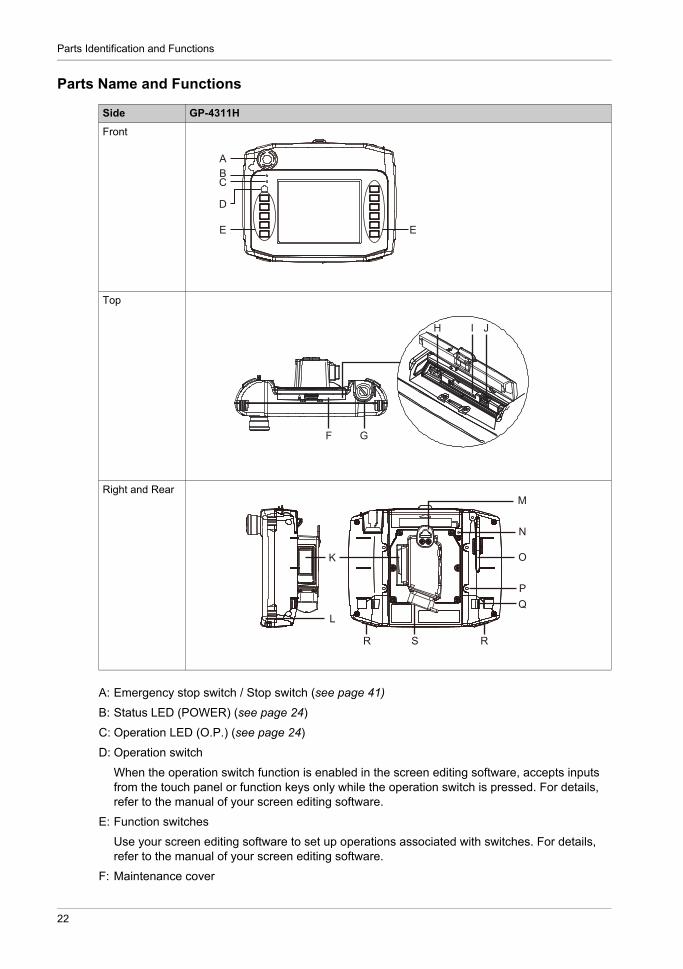
Parts Name and Functions
A: Emergency stop switch / Stop switch (see page 41)
B: Status LED (POWER) (see page 24)
C: Operation LED (O.P.) (see page 24)
D: Operation switch
When the operation switch function is enabled in the screen editing software, accepts inputs from the touch panel or function keys only while the operation switch is pressed. For details, refer to the manual of your screen editing software.
E: Function switches
Use your screen editing software to set up operations associated with switches. For details, refer to the manual of your screen editing software.
F: Maintenance cover
Side GP-4311H
Front
Top
Right and Rear
ABC
D
E E
F G
H I J
N
O
PQ
R S
K
L
M
R
22

GP4000H Series Hardware Manual
G: Key switch (see page 43)
H: USB (Type A) interface
I: SD card slot
J: USB (mini-B) interface
K: 3-position enable switch (see page 42)
L: Neck strap attachment slot
M: Hanger
Hanger for temporarily hanging this product on a wall. We recommend the panel, hooks and screws defined below for use with the Hanger.
*1 Even if the installation wall thickness is within the recommended range, depending on wall’s material, size, and installation location of this product and other devices, the installation wall could warp. To prevent warping, the installation surface may need to be strengthened.
N: SD card access LED (see page 24)
O: Touch pen
P: Wall hanging adapter attachment slots
By attaching a Wall Hanging Adapter (model number: GP3000H-WMA-01), you can secure this product to a panel or commercially available arm.
Q: Hand strap attachment slots
R: Insertion hole (with cover) for function switch sheet
S: Interface for direct-connect cable (with connector cover) (see page 37)
Panel Panel thickness: 1 to 1.6 mm (0.04 to 0.06 in)*1
Panel width: 14 mm (0.55 in) or more.
Hook Diameter 7 mm (0.27 in) or less, Rod-shaped or S-shaped hook.
Screw M4 pan-head machine screws. Head diameter of 7 mm (0.27 in) or less.
23

Parts Identification and Functions
LED Indications
Status LED
*1 Make sure your screen editing software supports the function.
Operation LED
SD card access LED
Color Indicator HMI operation Logic program operation*1
Green ON Offline -
In operation RUN
Flashing In operation STOP
LED fade*1 Backlight OFF (Standby Mode)
Orange Flashing Software starting up.
Red ON Power is ON.
Flashing In operation Major error
- OFF Power is OFF.
Color Indicator Description
Green ON Indicates the Operation Switch is ON.
- OFF Indicates the Operation Switch is OFF.
Color Indicator Description
Green ON The SD Card is inserted.
- OFF The SD Card is not inserted or is not being accessed.
24

GP4000H Series Hardware Manual
Specifications
KanpaiHandy_GP4000H 5/2016
GP4000H Series Hardware Manual
Specifications
Chapter 4Specifications
What Is in This Chapter?
This chapter contains the following sections:
Section Topic Page
4.1 General Specifications 26
4.2 Functional Specifications 30
4.3 Interface Specifications 33
25

Specifications
General Specifications
Section 4.1General Specifications
What Is in This Section?
This section contains the following topics:
Topic Page
Electrical Specifications 27
Environmental Specifications 28
Structural Specifications 29
26

GP4000H Series Hardware Manual
Electrical Specifications
Po
wer
sup
ply
Rated input voltage 24 Vdc
Input voltage limits 19.2...28.8 Vdc
Voltage drop 10 ms or less
Pow
er c
onsu
mpt
ion Maximum Power
Consumption12 W or less
When power is not supplied to external devices
8 W or less
In-rush current 35 A or less
Voltage endurance 500 Vac, 20 mA for 1 minute (between charging and FG terminals)
Insulation resistance 500 Vdc, 10 MΩ or more (between charging and FG terminals)
27

Specifications
Environmental Specifications
NOTE: When using any of this product’s options, check the specifications for any special conditions or cautions that may apply.
Air quality requirements
Do not operate or store this product where chemicals evaporate, or where chemicals are present in the air:
Corrosive chemicals: Acids, alkalines, liquids containing salt. Flammable chemicals: Organic solvents.
Physical environment
Surrounding air temperature 0...40 °C (32...104 °F)
Storage temperature -20...60 °C (-4...140 °F)
Surrounding air and storage humidity
10...90% RH (Non condensing, wet bulb temperature 39 °C [102.2 °F] or less)
Dust 0.1 mg/m3 (10-7 oz/ft3) or less (non-conductive levels)
Pollution degree For use in Pollution Degree 2 environment
Corrosive gases Free of corrosive gases
Atmospheric pressure (operating altitude)
800...1,114 hPa (2,000 m [6,561 ft] or lower)
Mechanical environment
Vibration resistance IEC/EN 61131-2 compliant5...9 Hz Single amplitude 3.5 mm (0.14 in)
9...150 Hz Fixed acceleration: 9.8 m/s2
X, Y, Z directions for 10 cycles (approximately 100 minutes)
Shock resistance IEC/EN 61131-2 compliant
147 m/s2, X, Y, Z directions for 3 times
Drop resistance IEC 61131-2 compliant1.0 m [3.3 ft] drop - 2 times
Electrical environment
Noise immunity Noise voltage: 1,000 Vp-pPulse duration: 1 sRise time: 1 ns(via noise simulator)
Electrostatic discharge immunity Contact discharge method: 6 kV (IEC/EN 61000-4-2 Level 3)
CAUTIONINOPERATIVE EQUIPMENT
Do not allow water, liquids, metal, and wiring fragments to enter this product.
Failure to follow these instructions can result in injury or equipment damage.
28

GP4000H Series Hardware Manual
Structural Specifications
*1 This product has been tested using conditions equivalent to the standards shown in the specification. Therefore, prior to using this product, be sure to confirm the type of conditions that will be present in this product 's operating environment.
Grounding Functional grounding: Grounding resistance of 100 Ω, 2 mm2 (AWG 14) or thicker wire, or your country's applicable standard (same for FG and SG terminals).
Cooling method Natural air circulation
Structure*1 Equivalent to IP65
External dimensions(W x H x D)
224 x 178.3 x 87.6 mm (8.82 x 7.02 x 3.45 in): without any Stop Switch224 x 178.3 x 107.5 mm (8.82 x 7.02 x 4.23 in): with an Emergency Stop Switch or a Stop SwitchRefer to Dimensions (see page 49).
Weight 910 g (2.01 lb) or less: without a Key Switch, unit only960 g (2.12 lb) or less: with a Key Switch, unit only
CAUTIONEQUIPMENT DAMAGE
Ensure this product is not in permanent and direct contact with oils. Do not press on the display of this product with excessive force or with a hard object. Do not press on the touch panel with a pointed object, such as the tip of a mechanical pencil
or a screwdriver.
Failure to follow these instructions can result in injury or equipment damage.
CAUTIONEQUIPMENT DAMAGE
Do not expose the device to direct sunlight.
Failure to follow these instructions can result in injury or equipment damage.
NOTICESTORAGE AND OPERATION OUTSIDE OF SPECIFICATIONS
Store this product in areas where temperatures are within the product’s specifications. Do not restrict or block this product’s ventilation slots.
Failure to follow these instructions can result in equipment damage.
29

Specifications
Functional Specifications
Section 4.2Functional Specifications
What Is in This Section?
This section contains the following topics:
Topic Page
Display Specifications 31
Memory, Clock, Touch Panel 32
30

GP4000H Series Hardware Manual
Display Specifications
Display type TFT Color LCD
Display size 5.7”
Resolution 640 x 480 pixels (VGA)
Effective display area (W x H)
115.2 x 86.4 mm (4.54 x 3.4 in)
Display colors 65,536 colors (No blink) / 16,384 colors (Blink)For details about display colors, refer to the manual for your screen editing software.
Backlight White LED (Not user replaceable. When replacement is required, contact your local distributor.)
Backlight service life 50,000 hours or more (continuous operation at 25 °C [77 °F] before backlight brightness decreases to 50%
Brightness control 16 levels (Adjusted with touch panel)
31
Specifications
Memory, Clock, Touch Panel
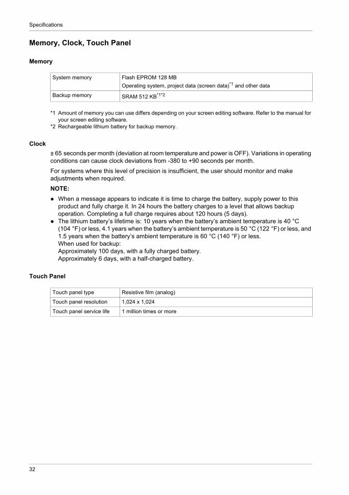
Memory
*1 Amount of memory you can use differs depending on your screen editing software. Refer to the manual for your screen editing software.
*2 Rechargeable lithium battery for backup memory.
Clock
± 65 seconds per month (deviation at room temperature and power is OFF). Variations in operating conditions can cause clock deviations from -380 to +90 seconds per month.
For systems where this level of precision is insufficient, the user should monitor and make adjustments when required.
NOTE:
When a message appears to indicate it is time to charge the battery, supply power to this product and fully charge it. In 24 hours the battery charges to a level that allows backup operation. Completing a full charge requires about 120 hours (5 days).
The lithium battery’s lifetime is: 10 years when the battery’s ambient temperature is 40 °C (104 °F) or less, 4.1 years when the battery’s ambient temperature is 50 °C (122 °F) or less, and 1.5 years when the battery’s ambient temperature is 60 °C (140 °F) or less.When used for backup:Approximately 100 days, with a fully charged battery.Approximately 6 days, with a half-charged battery.
Touch Panel
System memory Flash EPROM 128 MB
Operating system, project data (screen data)*1 and other data
Backup memory SRAM 512 KB*1*2
Touch panel type Resistive film (analog)
Touch panel resolution 1,024 x 1,024
Touch panel service life 1 million times or more
32
GP4000H Series Hardware Manual
Interface Specifications
Section 4.3Interface Specifications
What Is in This Section?
This section contains the following topics:
Topic Page
Interface Specifications 34
Interface Connection 36
Interface for direct-connect cable 37
Serial Interface 39
Emergency Stop Switch / Stop Switch Output Interface 41
3-Position Enable Switch Output Interface 42
Key Switch Output Interface 43
DC Power Interface 44
Connecting the Power Supply 45
Grounding 47
33

Specifications
Interface Specifications
USB (Type A) interface Connector USB 2.0 (Type A) x 1
Power supply voltage 5 Vdc ±5%
Maximum current supplied 500 mA/port
Maximum transmission distance
Less than 5 m (16.4 ft)
USB (mini-B) interface Connector USB 2.0 (mini-B) x 1
Maximum transmission distance
Less than 5 m (16.4 ft)
SD card interface SD card slot x 1, SD/SDHC card of up to 32 GB.
Inte
rfac
e fo
r di
rect
-con
nect
cab
le Serial interface Asynchronous transmission
RS-232C/RS-422/RS-485
Data length 7 or 8 bits
Stop bit 1 or 2 bits
Parity None, odd, or even
Data transmission speed 2,400...115,200 bps, 187,500 bps (MPI)
Maximum communication
distance*1
When using RS-232C: 15 m (49.2 ft)When using RS-422 at 115,200 bps: 1,200 m (3,937 ft)
Ethernet interface Standard IEEE802.3i/IEEE802.3u, 10BASE-T/100BASE-TX
Maximum communication
distance*1
100 m (328.1 ft)
Emergency stop switch / stop switch output interface
Contacts a-contact (normally open): 1b-contact (normally closed): 2
Rated voltage 30 Vdc
Maximum rated current 1 A(minimum allowable load: 5 Vdc, 1 mA)
Standard*2 IEC/EN 60947-5-1, 60947-5-5UL508, CSA C22.2 No.14
3-Position enable switch output interface
Contacts a-contact (normally open): 2
Rated voltage 30 Vdc
Maximum rated current 700 mA(minimum allowable load: 3 Vdc, 5 mA)
Standards*2 IEC/EN 60947-5-8, 60204-1UL508, CSA C22.2 No.14ISO 12100/EN 12100-1, 2ISO 11161/prEN 11161ISO 10218/EN 775ANSI/RIA R15.06, ANSI B11.19
Key switch output interface Contacts c-contact: 1 (can be set normally open or normally closed)
Rated voltage 24 Vdc
Maximum rated current 300 mA
34

GP4000H Series Hardware Manual
*1 When using the Conversion Adapter (model number: AGP3000H-ADPCOM-01), the distance includes the cable length between this product and the Conversion Adapter.
*2 Overall system may not meet these standards if implemented outside these parameters. Follow these stan-dards when designing the system.
*3 The conversion adapter is required to use the external output interface (DOUT) and build a system. For de-tails, refer to the installation guide of conversion adapter.
External output
interface*3
DOUT output Open collector output 2 points (function switches, F1 and F2 keys)
Rated voltage 24 Vdc
Maximum rated current 300 mA/point
Operation output
Open collector output 1 point
Rated voltage 24 Vdc
Maximum rated current 300 mA
External Buzzer output
Open collector output 1 point
Rated voltage 24 Vdc
Maximum rated current 300 mA
35

Specifications
Interface Connection
Cable Connections
A direct-connect cable (sold separately) is required to connect to external devices for communication, power, or wiring of switches.
A conversion adapter (model number: AGP3000H-ADPCOM-01) is required to build a system with an external output interface, such as DOUT.
NOTE: For the kinds of the direct-connect cable, refer to Accessories (see page 19). UL certification has been achieved for this product with the conversion adapter, and with the
direct-connect cables. For details on the conversion adapter, refer to the installation guide of conversion adapter. For instructions on how to connect to other devices, always refer to the corresponding device
driver manual of your screen editing software. Use only the SELV (Safety Extra-Low Voltage) circuit to connect the COM, USB, and LAN
interfaces.
DANGERHAZARD OF ELECTRIC SHOCK, EXPLOSION, OR ARC FLASH
Remove all power from the device before removing any covers or elements of the system, and prior to installing or removing any accessories, hardware, or cables.
Unplug the power cable from both this product and the power supply. Always use a properly rated voltage sensing device to confirm power is off. Replace and secure all covers or elements of the system before applying power to this
product. Use only the specified voltage when operating this product. This product is designed to use
24 Vdc. Always check whether your device is DC powered before applying power.
Failure to follow these instructions will result in death or serious injury.
CAUTIONEQUIPMENT DAMAGE
To prevent damage, do not allow the cable's connector to drop or hit against anything hard. Connect peripheral equipment first, and connect this product last. Otherwise, the RS-
232C/RS-422/RS-485 circuit may become inoperable. Properly terminate unused wires to help avoid short-circuits by other signals or metal parts. After cable length adjustment, connect the shield on the cable to the FG terminal.
Failure to follow these instructions can result in injury or equipment damage.
36

GP4000H Series Hardware Manual
Interface for Direct-connect Cable
(Cable side)
8 7 6 5 4 3 2 1
D
C
B
A
Pin No.
Signal name Description Cable color / Marking color,
number*1
D7 KEY_NC Key switch output signalb-contact: normally closedRating: 24 Vdc, 300 mA
Orange/None
D8 KEY_NO Key switch output signala-contact: normally openRating: 24 Vdc, 300 mA
Orange/Black 1
C7 ENB0A 3-position enable switch output signala-contact: normally openRating: 30 Vdc, 700 mA
Blue/Black 2
B7 ENB0B 3-position enable switch output signala-contact: normally open
Blue/Black 3
A6 ENB1A 3-position enable switch output signala-contact: normally openRating: 30 Vdc, 700 mA
Blue/None
A7 ENB1B 3-position enable switch output signala-contact: normally open
Blue/Black 1
C6 EMG0A Emergency stop switch / stop switch output signala-contact: normally openRating: 30 Vdc, 1 A
Purple/Black 2
B6 EMG0B Emergency stop switch / stop switch output signala-contact: normally open
Purple/White 3
A5 EMG1A Emergency stop switch / stop switch output signalb-contact: normally closedRating: 30 Vdc, 1 A
Purple/Black 1
D6 EMG1B Emergency stop switch / stop switch output signalb-contact: normally closed
Purple/White 2
C5 EMG2A Emergency stop switch / stop switch output signalb-contact: normally closedRating: 30 Vdc, 1 A
Purple/None
B5 EMG2B Emergency stop switch / stop switch output signalb-contact: normally closed
Purple/White 1
37
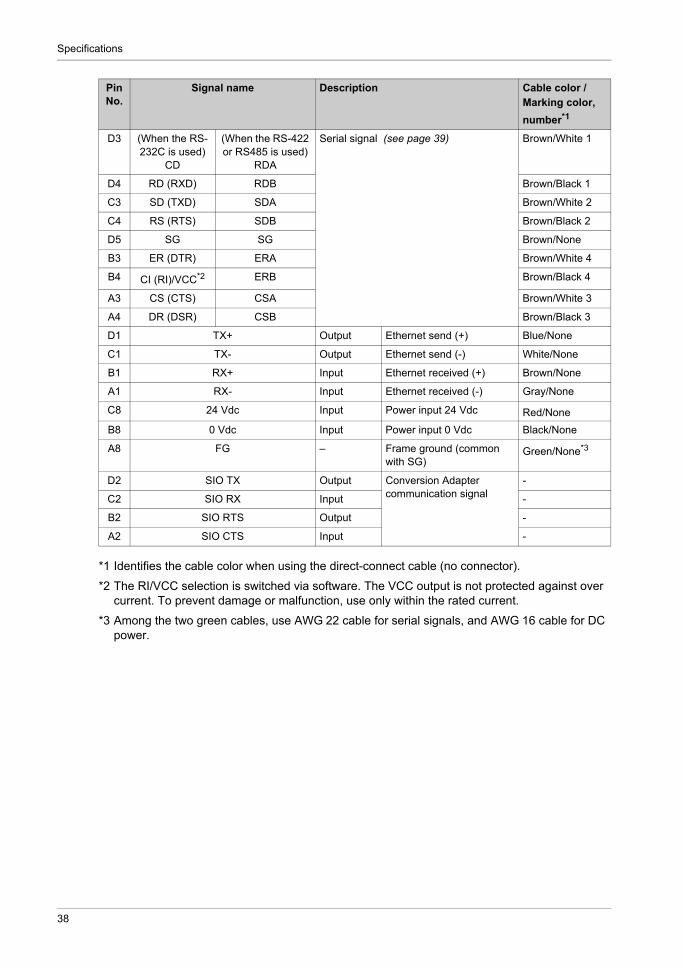
Specifications
*1 Identifies the cable color when using the direct-connect cable (no connector).
*2 The RI/VCC selection is switched via software. The VCC output is not protected against over current. To prevent damage or malfunction, use only within the rated current.
*3 Among the two green cables, use AWG 22 cable for serial signals, and AWG 16 cable for DC power.
D3 (When the RS-232C is used)
CD
(When the RS-422 or RS485 is used)
RDA
Serial signal (see page 39) Brown/White 1
D4 RD (RXD) RDB Brown/Black 1
C3 SD (TXD) SDA Brown/White 2
C4 RS (RTS) SDB Brown/Black 2
D5 SG SG Brown/None
B3 ER (DTR) ERA Brown/White 4
B4 CI (RI)/VCC*2 ERB Brown/Black 4
A3 CS (CTS) CSA Brown/White 3
A4 DR (DSR) CSB Brown/Black 3
D1 TX+ Output Ethernet send (+) Blue/None
C1 TX- Output Ethernet send (-) White/None
B1 RX+ Input Ethernet received (+) Brown/None
A1 RX- Input Ethernet received (-) Gray/None
C8 24 Vdc Input Power input 24 Vdc Red/None
B8 0 Vdc Input Power input 0 Vdc Black/None
A8 FG – Frame ground (common with SG)
Green/None*3
D2 SIO TX Output Conversion Adapter communication signal
-
C2 SIO RX Input -
B2 SIO RTS Output -
A2 SIO CTS Input -
Pin No.
Signal name Description Cable color / Marking color,
number*1
38

GP4000H Series Hardware Manual
Serial Interface
Introduction
For information on how to connect controllers and other types of equipment, refer to the corresponding device driver manual of your screen editing software.
Connect to the D-SUB 9-pin plug type connector.
You can switch the communication method between RS-232C and RS-422/RS-485 via the software.
The serial interface is not isolated. The SG (signal ground) and the FG (functional ground) terminals are connected inside this product.
NOTE: Use within the rated current.
RS-232C
*1 The RI/VCC selection is switched via software. The VCC output is not protected against over current. To prevent damage or malfunction, use only within the rated current.
Interfit bracket is #4-40 (UNC).
Recommendations:
Cable Connector: XM3D-0921 manufactured by OMRON Corporation. Cable Cover: XM2S-0913 manufactured by OMRON Corporation. Jack Screw (#4-40 UNC): XM2Z-0073 manufactured by OMRON Corporation.
DANGERELECTRIC SHOCK AND FIRE
When using the SG terminal to connect an external device to this product: Verify that a short-circuit loop is not created when you set up the system. Connect the SG terminal to remote equipment when the external device is not isolated. Connect the SG terminal to a known reliable ground connection to reduce the risk of damaging
the circuit.
Failure to follow these instructions will result in death or serious injury.
RS-232C
Signal name Direction Meaning
CD Input Carrier detect
RD (RXD) Input Receive data
SD (TXD) Output Send data
ER (DTR) Output Data terminal ready
SG – Signal ground
DR (DSR) Input Data set ready
RS (RTS) Output Request to send
CS (CTS) Input Send possible
CI (RI)/VCC*1 Input Called status display5 Vdc ±5% Output 0.25 A
FG – Frame ground (common with SG)
39

Specifications
The direct-connect cable’s serial interface is not isolated. When the host (PLC) unit is also not isolated, be sure to connect the SG (Signal Ground) terminal.
You can set up isolation with the RS-232C Isolation Unit (model number CA3-ISO232-01) and the following recommended equipment.
Recommendations:
Intermediate Connector: XM3A-0921 manufactured by OMRON Corporation. Cable Cover: XM2S-0913 manufactured by OMRON Corporation. Fastener 1: XM2Z-0003 manufactured by OMRON Corporation.
RS-422/RS-485
Interfit bracket is #4-40 (UNC).
Recommendations:
Cable Connector: XM3D-0921 manufactured by OMRON Corporation. Cable Cover: XM2S-0913 manufactured by OMRON Corporation. Jack Screw (#4-40 UNC): XM2Z-0073 manufactured by OMRON Corporation.
RS-422/RS-485
Signal name Direction Meaning
RDA Input Receive data A (+)
RDB Input Receive data B (-)
SDA Output Send data A (+)
ERA Output Data terminal ready A (+)
SG – Signal ground
CSB Input Send possible B (-)
SDB Output Send data B (-)
CSA Input Send possible A (+)
ERB Output Data terminal ready B (-)
FG – Frame ground (common with SG)
40

GP4000H Series Hardware Manual
Emergency Stop Switch / Stop Switch Output InterfaceWith this product incorporating an emergency stop switch or stop switch, the switch activates the contact output, when the switch is enabled. To reset the stop status (lock status), pull the button forward, or turn the button in the direction indicated by the arrow.
When the switch is pressed, the ON/OFF status are as follows:
Contact state in brackets ( ).
NOTE: When using a model without an emergency stop switch or a stop switch, disconnect (NC) these signal lines.
Signal name Stop reset Stop
EMG0 0 (OFF) 1 (ON)
EMG1 1 (ON) 0 (OFF)
EMG2 1 (ON) 0 (OFF)
EMG2AEMG1AEMG0A
EMG0BEMG1BEMG2B
41

Specifications
3-Position Enable Switch Output Interface
The 3-position enable switch has three positions: 1) Not pressed (released position), 2) Pressed to the intermediate position, 3) Pressed to the innermost position (fully closed).
The continuity between ENB0 to ENB1 during each position of the switch is as follows.
Contact state in brackets ( ).
NOTE: The contact is OFF when the switch is pressed to the innermost position then returned to the not pressed position.
Signal name Not pressed Pressed to the intermediate position
Pressed to the innermost position
ENB0 0 (OFF) 1 (ON) 0 (OFF)
ENB1 0 (OFF) 1 (ON) 0 (OFF)
ENB1AENB0A
ENB0BENB1B
42

GP4000H Series Hardware Manual
Key Switch Output Interface
Turning the key turns this product's power supply ON or OFF.
NOTE:
When the key is not turned to ON or OFF, either the “KEY_NO” or the “KEY_NC” signal is ON. These signals will not simultaneously turn OFF.
These signal lines must be disconnected (NC) when the model without a key switch is used.
Signal name Turn OFF this product Turn ON this product
KEY_NO 0 (OFF) 1 (ON)
KEY_NC 1 (ON) 0 (OFF)
OFF
DC24VKEY_NOKEY_NC
Cable This product
ONDC24V
KEY_NOKEY_NC
Cable This product
43

Specifications
DC Power Interface
Connecting the DC Power Cord
NOTE: The SG (signal ground) and FG (functional ground) terminals are connected internally in this
product. When the FG terminal is connected, be sure the wire is grounded. Not grounding this product
can result in excessive electromagnetic interference (EMI).
DANGERHAZARD OF ELECTRIC SHOCK, EXPLOSION, OR ARC FLASH
Remove all power from the device before removing any covers or elements of the system, and prior to installing or removing any accessories, hardware, or cables.
Unplug the power cable from both this product and the power supply. Always use a properly rated voltage sensing device to confirm power is off. Replace and secure all covers or elements of the system before applying power to this
product. Use only the specified voltage when operating this product. This product is designed to use
24 Vdc power. Always check whether your device is DC powered before applying power. Be sure to ground this product's FG terminal.
Failure to follow these instructions will result in death or serious injury.
44

GP4000H Series Hardware Manual
Connecting the Power Supply
Precautions
Use copper wire rated for 60 C (140 F). When using the direct-connect cable (no connector), it's recommended to use the provided
common mode filter on the cable to reduce noise.
NOTE: The above image is an example internal circuit for a common mode filter. For the actual circuit in use, refer to the specifications of your common mode filter.
Improving Noise/Surge Resistance
This product’s power supply cord should not be bundled with or kept close to main circuit lines (high voltage, high current), power lines, or input/output lines, and their various systems should be kept separate. When power lines cannot be wired via a separate system, use shielded cables for input/output lines.
Make the power cord as short as possible, and be sure to twist the ends of the wires together (i.e. twisted pair cabling) from close to the power supply unit.
If there is an excess amount of noise on the power supply line, connect a noise reducing transistor before turning on the power.
Connect a lightning surge absorber device to handle power surges. To increase noise resistance, attach a ferrite core to the power cable.
This product
24 Vdc
FG
0 Vdc
Common mode filterExternal power supply
24 Vdc
0 Vdc
The black square indicates the connection point for the direct-connect cable and common field filter.
45
Specifications
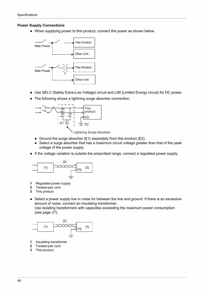
Power Supply Connections
When supplying power to this product, connect the power as shown below.
Use SELV (Safety Extra-Low Voltage) circuit and LIM (Limited Energy circuit) for DC power.
The following shows a lightning surge absorber connection:
Ground the surge absorber (E1) separately from this product (E2). Select a surge absorber that has a maximum circuit voltage greater than that of the peak
voltage of the power supply.
If the voltage variation is outside the prescribed range, connect a regulated power supply.
1 Regulated power supply2 Twisted-pair cord3 This product
Select a power supply low in noise for between the line and ground. If there is an excessive amount of noise, connect an insulating transformer.Use isolating transformers with capacities exceeding the maximum power consumption (see page 27).
1 Insulating transformer2 Twisted-pair cord3 This product
E1 E2
FG
Thisproduct
Lightning Surge Absorber
46
GP4000H Series Hardware Manual
Grounding
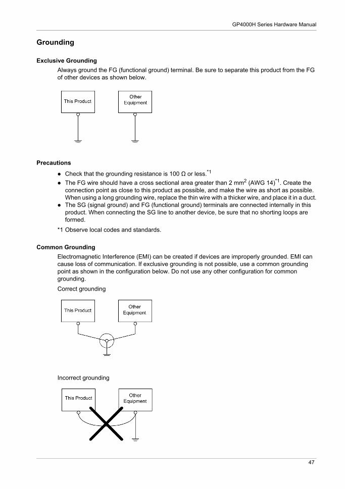
Exclusive Grounding
Always ground the FG (functional ground) terminal. Be sure to separate this product from the FG of other devices as shown below.
Precautions
Check that the grounding resistance is 100 Ω or less.*1
The FG wire should have a cross sectional area greater than 2 mm2 (AWG 14)*1. Create the connection point as close to this product as possible, and make the wire as short as possible. When using a long grounding wire, replace the thin wire with a thicker wire, and place it in a duct.
The SG (signal ground) and FG (functional ground) terminals are connected internally in this product. When connecting the SG line to another device, be sure that no shorting loops are formed.
*1 Observe local codes and standards.
Common Grounding
Electromagnetic Interference (EMI) can be created if devices are improperly grounded. EMI can cause loss of communication. If exclusive grounding is not possible, use a common grounding point as shown in the configuration below. Do not use any other configuration for common grounding.
Correct grounding
Incorrect grounding
47

Specifications
48

GP4000H Series Hardware Manual
Dimensions
KanpaiHandy_GP4000H 5/2016
GP4000H Series Hardware Manual
Dimensions
Chapter 5Dimensions
What Is in This Chapter?
This chapter contains the following topics:
Topic Page
External Dimensions 50
Dimensions with Emergency Switch Guard 52
49

Dimensions
External Dimensions
Models with an Emergency Stop Switch or Stop Switch
NOTE: External view is shown using first angle projection method.
1 Front2 Left3 Bottom
2248.82
174
6.85
4.3
0.17
mmin
(1) (2)
(3)
106.84.2
86.43.4
0.70.03
50

GP4000H Series Hardware Manual
Models without any Stop Switch
NOTE: External view is shown using first angle projection method.
1 Front2 Left3 Bottom
2248.82
174
6.85
4.3
0.17
mmin
(1) (2)
(3)
86.93.4286.43.4
0.70.03
51

Dimensions
Dimensions with a Stop Switch Guard
NOTE: External view is shown using first angle projection method.
1 Front2 Left3 Bottom
External Dimensions of the Stop Switch Guard
2248.82
174
6.85
4.3
0.17
mmin
(1) (2)
(3)
110.94.37
0.70.03
20.08
652.56
45 1.77
mmin
81.5
3.21
52

GP4000H Series Hardware Manual
Installation and Wiring
KanpaiHandy_GP4000H 5/2016
GP4000H Series Hardware Manual
Installation
Chapter 6Installation
What Is in This Chapter?
This chapter contains the following sections:
Section Topic Page
6.1 Fixing This Product 54
6.2 Direct-connect Cable Attaching/Removing 59
6.3 Attaching the Stop Switch Guard 63
6.4 Replacing the Function Switch Sheet 64
6.5 SD card Insertion/Removal 65
53

Installation and Wiring
Fixing This Product
Section 6.1Fixing This Product
What Is in This Section?
This section contains the following topics:
Topic Page
Introduction 55
Hand Strap 56
Neck Strap 57
Wall Hanging Adapter 58
54

GP4000H Series Hardware Manual
Introduction
Be aware of the following: This product is not designed for outdoor use. UL certification obtained is for indoor use only.
DANGERHAZARD OF ELECTRIC SHOCK, EXPLOSION, OR ARC FLASH
Remove all power from the device before removing any covers or elements of the system, and prior to installing or removing any accessories, hardware, or cables.
Unplug the power cable from both this product and the power supply. Always use a properly rated voltage sensing device to confirm power is off. Replace and secure all covers or elements of the system before applying power to this
product.
Failure to follow these instructions will result in death or serious injury.
CAUTIONEQUIPMENT DAMAGE
Use this product attached properly to a hand strap, neck strap (sold separately), or a wall hanging adapter (sold separately).
Do not operate or wire this product while it is hang on the wall with the Hanger, attached to the rear.
Failure to follow these instructions can result in injury or equipment damage.
55
Installation and Wiring
Hand Strap
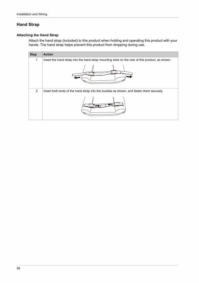
Attaching the Hand Strap
Attach the hand strap (included) to this product when holding and operating this product with your hands. The hand strap helps prevent this product from dropping during use.
Step Action
1 Insert the hand strap into the hand strap mounting slots on the rear of this product, as shown.
2 Insert both ends of the hand strap into the buckles as shown, and fasten them securely.
56

GP4000H Series Hardware Manual
Neck Strap
Attaching the Neck Strap
Attach the neck strap (model number: GP2000H-STRAP11) to this product so that the product can hang from your neck. The neck strap helps prevent this product from dropping during use.
NOTE: Hang the neck strap around your neck when operating this product.
Step Action
1 First remove the neck straps from the buckles on both ends. Next, insert the ends of the neck straps into the neck strap mounting slots, as shown.
2 Insert the neck straps into the buckles as shown, and fasten them securely.
57

Installation and Wiring
Wall Hanging Adapter
Attaching the Wall Hanging Adapter
You can mount this product to a wall or a commercially available arm with the Wall Hanging Adapter (model number: GP3000H-WMA-01). For details, refer to the Wall Hanging Adapter installation guide.
58
GP4000H Series Hardware Manual
Direct-connect Cable Attaching/Removing
Section 6.2Direct-connect Cable Attaching/Removing
What Is in This Section?
This section contains the following topics:
Topic Page
Introduction 60
Attaching the Cable 61
Removing the Cable 62
59

Installation and Wiring
Introduction
DANGERHAZARD OF ELECTRIC SHOCK, EXPLOSION, OR ARC FLASH
Remove all power from the device before removing any covers or elements of the system, and prior to installing or removing any accessories, hardware, or cables.
Unplug the power cable from both this product and the power supply. Always use a properly rated voltage sensing device to confirm power is off. Replace and secure all covers or elements of the system before applying power to this
product.
Failure to follow these instructions will result in death or serious injury.
CAUTIONEQUIPMENT DAMAGE
To prevent damage, do not allow the cable's connector to drop or hit against anything hard. Connect peripheral equipment first, and connect this product last. Otherwise, the RS-
232C/RS-422/RS-485 circuit may become inoperable. Properly terminate unused wires to help avoid short-circuits by other signals or metal parts. After cable length adjustment, connect the shield on the cable to the FG terminal.
Failure to follow these instructions can result in injury or equipment damage.
CAUTIONRISK OF INJURY
Handle with care. Do not drop this product. Do not step on cables.
Failure to follow these instructions can result in injury or equipment damage.
60

GP4000H Series Hardware Manual
Attaching the Cable
Step Action
1 Before connection, remove the cable's connector cap and this product’s connector cover. To remove the cable's connector cap, pull out the cable by holding the cable connector.
1 Cable’s connector cap2 Cable connector
NOTE: To disconnect this cable from the connector cap, be sure to hold the cable connector and pull it out. If you hold other parts of this cable (lock ring, etc.), the cable cannot be disconnected.
2 As illustrated, line up the arrow on this product with the arrow on the cable. Insert the cable connector into the product connector until you hear it click.
1 Arrows
NOTE: Be sure to insert the cable connector as shown.
3 Turn the cable connector lock ring to lock the connector, so that the small arrow (for LOCK) on the lock ring is aligned with the small arrow on the cable connector.
1 Lock ring2 Small arrows
1 2
1
1
2
61

Installation and Wiring
Removing the Cable
NOTE: Whenever the cable is removed, you cover the connector with a connector cover.
Step Action
1 Turn the lock ring so that the small arrow on the lock ring is displaced from the small arrow on the cable connector. Then, pull out the cable by holding the cable connector.
(1) Turn the lock ring(2) Pull out the cable
NOTE: To disconnect the cable, be sure to hold the cable connector and pull it out. If you hold other parts of the cable (lock ring, etc.), the cable cannot be disconnected.
(1)
(2)
62
GP4000H Series Hardware Manual
Attaching the Stop Switch Guard
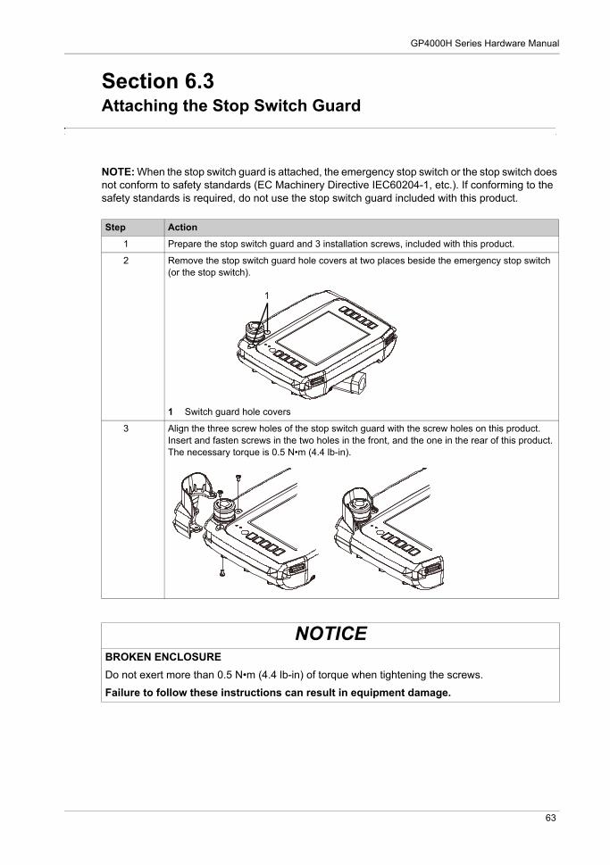
Section 6.3Attaching the Stop Switch Guard
NOTE: When the stop switch guard is attached, the emergency stop switch or the stop switch does not conform to safety standards (EC Machinery Directive IEC60204-1, etc.). If conforming to the safety standards is required, do not use the stop switch guard included with this product.
Step Action
1 Prepare the stop switch guard and 3 installation screws, included with this product.
2 Remove the stop switch guard hole covers at two places beside the emergency stop switch (or the stop switch).
1 Switch guard hole covers
3 Align the three screw holes of the stop switch guard with the screw holes on this product. Insert and fasten screws in the two holes in the front, and the one in the rear of this product.The necessary torque is 0.5 N•m (4.4 lb-in).
NOTICEBROKEN ENCLOSURE
Do not exert more than 0.5 N•m (4.4 lb-in) of torque when tightening the screws.
Failure to follow these instructions can result in equipment damage.
1
63

Installation and Wiring
Replacing the Function Switch Sheet
Section 6.4Replacing the Function Switch Sheet
Step Action
1 Remove the cover of the insertion hole and pull out the current sheet.
2 Insert the new sheet and put the cover back on the insertion hole.
1 Function switch sheet
NOTE:
Insert the cover on the insertion hole all the way in. Failure to do so will reduce the water resistance.
The cover cannot be pressed into place if the sheet sticks out from the insertion hole. Use a touch pen (included) to push the sheet all the way into this product.
To simplify insertion of the function switch sheet, bend the edge on the dotted line, as shown.
1
64
GP4000H Series Hardware Manual
SD Card Insertion/Removal
Section 6.5SD Card Insertion/Removal
What Is in This Section?
This section contains the following topics:
Topic Page
Introduction 66
Inserting the SD Card 67
Removing the SD Card 68
SD Card Data Backup 70
65
Installation and Wiring
Introduction
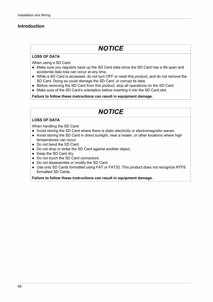
NOTICELOSS OF DATA
When using a SD Card: Make sure you regularly back up the SD Card data since the SD Card has a life span and
accidental data loss can occur at any time. While a SD Card is accessed, do not turn OFF or reset this product, and do not remove the
SD Card. Doing so could damage the SD Card, or corrupt its data. Before removing the SD Card from this product, stop all operations on the SD Card. Make sure of the SD Card’s orientation before inserting it into the SD Card slot.
Failure to follow these instructions can result in equipment damage.
NOTICELOSS OF DATA
When handling the SD Card: Avoid storing the SD Card where there is static electricity or electromagnetic waves. Avoid storing the SD Card in direct sunlight, near a heater, or other locations where high
temperatures can occur. Do not bend the SD Card. Do not drop or strike the SD Card against another object. Keep the SD Card dry. Do not touch the SD Card connectors. Do not disassemble or modify the SD Card. Use only SD Cards formatted using FAT or FAT32. This product does not recognize NTFS
formatted SD Cards.
Failure to follow these instructions can result in equipment damage.
66
GP4000H Series Hardware Manual
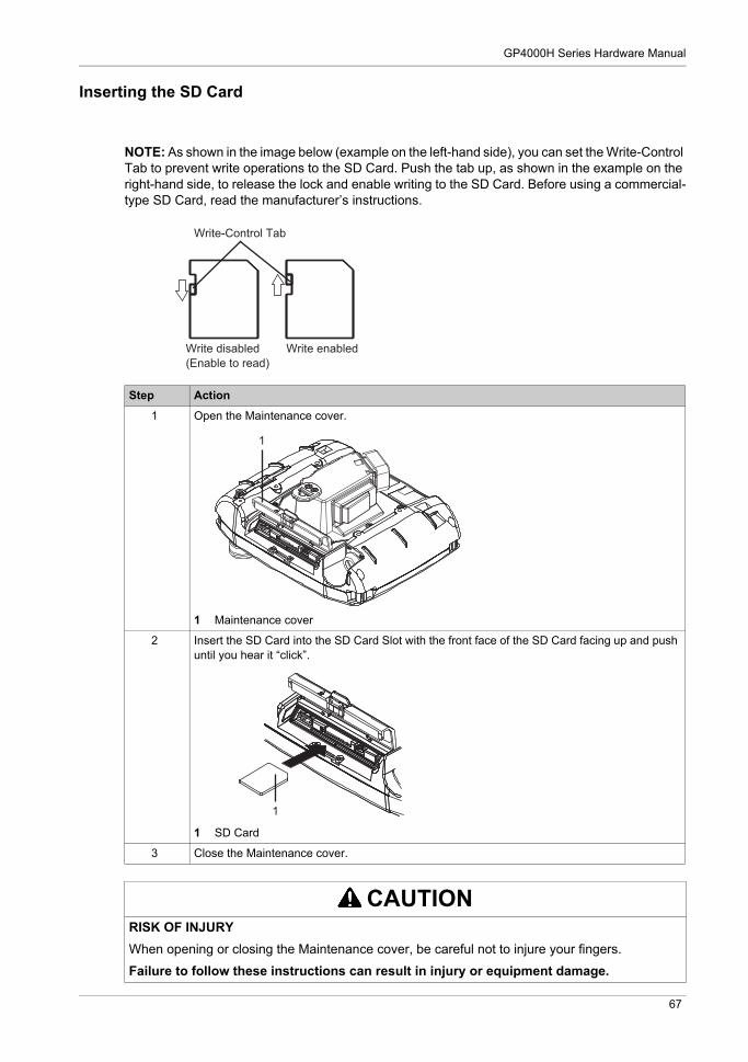
Inserting the SD Card
NOTE: As shown in the image below (example on the left-hand side), you can set the Write-Control Tab to prevent write operations to the SD Card. Push the tab up, as shown in the example on the right-hand side, to release the lock and enable writing to the SD Card. Before using a commercial-type SD Card, read the manufacturer’s instructions.
Step Action
1 Open the Maintenance cover.
1 Maintenance cover
2 Insert the SD Card into the SD Card Slot with the front face of the SD Card facing up and push until you hear it “click”.
1 SD Card
3 Close the Maintenance cover.
CAUTIONRISK OF INJURY
When opening or closing the Maintenance cover, be careful not to injure your fingers.
Failure to follow these instructions can result in injury or equipment damage.
Write-Control Tab
Write disabled(Enable to read)
Write enabled
1
1
67
Installation and Wiring
Removing the SD Card
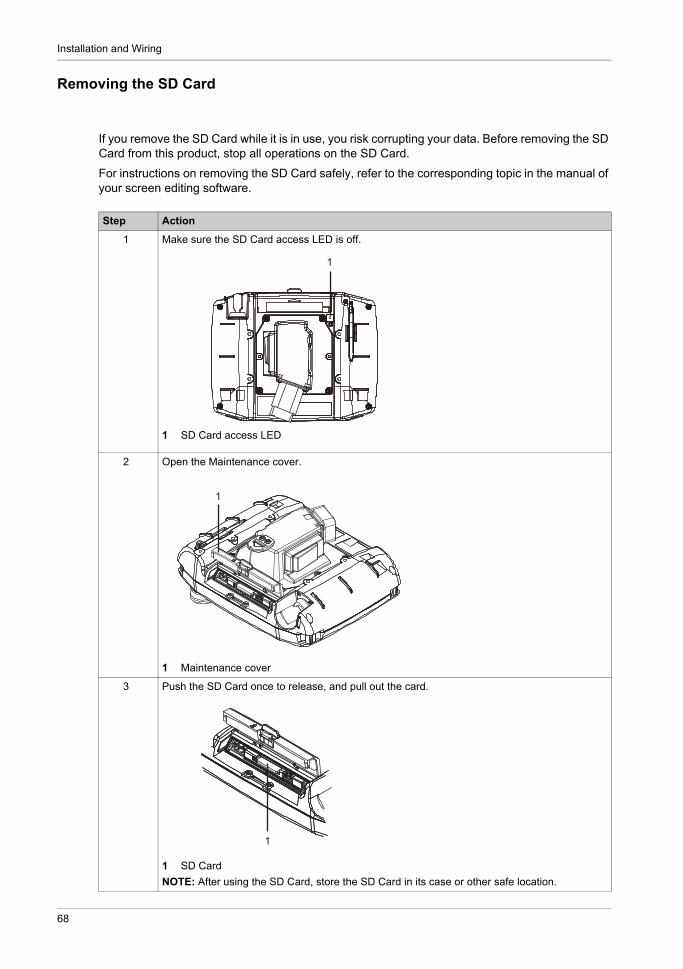
If you remove the SD Card while it is in use, you risk corrupting your data. Before removing the SD Card from this product, stop all operations on the SD Card.
For instructions on removing the SD Card safely, refer to the corresponding topic in the manual of your screen editing software.
Step Action
1 Make sure the SD Card access LED is off.
1 SD Card access LED
2 Open the Maintenance cover.
1 Maintenance cover
3 Push the SD Card once to release, and pull out the card.
1 SD Card
NOTE: After using the SD Card, store the SD Card in its case or other safe location.
1
1
1
68

GP4000H Series Hardware Manual
4 Close the Maintenance cover.
CAUTIONRISK OF INJURY
When opening or closing the Maintenance cover, be careful not to injure your fingers.
Failure to follow these instructions can result in injury or equipment damage.
Step Action
69

Installation and Wiring
SD Card Data Backup
To make your backups, you can either insert the SD Card directly into the SD Card Slot on your computer, or use a commercially available SD Card reader.
70

GP4000H Series Hardware Manual
Maintenance
KanpaiHandy_GP4000H 5/2016
GP4000H Series Hardware Manual
Maintenance
Chapter 7Maintenance
What Is in This Chapter?
This chapter contains the following topics:
Topic Page
Regular Cleaning 72
Periodic Check Points 73
Replacing the Backlight 74
After-sales Service 75
71

Maintenance
Regular Cleaning
Cleaning this product
When this product gets dirty, soak a soft cloth in water with a neutral detergent, wring the cloth tightly and wipe this product.
NOTICEEQUIPMENT DAMAGE
Power off this product before cleaning it. Do not use hard or pointed objects to operate the touch panel as you may damage the panel
surface. Do not use paint thinner, organic solvents, or a strong acid compound to clean the unit.
Failure to follow these instructions can result in equipment damage.
72
GP4000H Series Hardware Manual
Periodic Check Points
Operation Environment
Is the operating temperature within the allowable range? (0...40 °C [32...104 °F]) Is the operating humidity within the specified range? (10...90% RH, wet bulb temperature of
39 °C [102.2 °F] or less) Is the operating atmosphere free of corrosive gases?
When this product is inside a panel, the ambient environment refers to the interior of the panel.
Electrical Specifications
Is the input voltage appropriate? (19.2...28.8 Vdc) Are all power cords and cables connected properly? Are there any loose cables?
Unit Disposal
When disposing this product, dispose it in a manner appropriate to, and in accordance with, your country's industrial machinery disposal/recycling standards.
73

Maintenance
Replacing the Backlight
Not user replaceable. When replacement is required, contact your local distributor.
74

GP4000H Series Hardware Manual
After-sales Service
Information
For details on after-sales service, refer to Pro-face website at
http://www.pro-face.com/trans/en/manual/1001.html
75