gpfs aix clusters concepts, planning, and installation · pdf filegeneral parallel file...
TRANSCRIPT

General Parallel File System for AIX 5L
AIX Clusters Concepts, Planning, andInstallation Guide
GA22-7895-01
���


General Parallel File System for AIX 5L
AIX Clusters Concepts, Planning, andInstallation Guide
GA22-7895-01
���

Note:Before using this information and the product it supports, be sure to read the general information under “Notices” on page 69.
Second Edition (December 2002)
This edition applies to version 2 release 1 of the IBM General Parallel File System for AIX 5L licensed program(number 5765-F64) and to all subsequent releases and modifications until otherwise indicated in new editions.
This edition replaces GA22-7895-01. Significant changes or additions to the text and illustrations are indicated by avertical line ( | ) to the left of the change.
IBM welcomes your comments. A form for your comments may be provided at the back of this publication, or youmay address your comments to:
International Business Machines CorporationDepartment 55JA, Mail Station P3842455 South RoadPoughkeepsie, NY 12601-5400United States of America
FAX (United States and Canada): 1+845+432-9405FAX (Other Countries):
Your International Access Code +1+845+432-9405
IBMLink™ (United States customers only): IBMUSM10(MHVRCFS)Internet e-mail: [email protected]
If you would like a reply, be sure to include your name, address, telephone number, or FAX number.
Make sure to include the following in your comment or note:v Title and order number of this book
v Page number or topic related to your comment
When you send information to IBM, you grant IBM a nonexclusive right to use or distribute the information in anyway it believes appropriate without incurring any obligation to you.
Permission to copy without fee all or part of MPI: A Message Passing Interface Standard, Version 1.2 and Version2.0 Message Passing Interface Forum is granted, provided the University of Tennessee copyright notice and the titleof the document appear, and notice is given that copying is by permission of the University of Tennessee. ©1995,1996, and 1997 University of Tennessee, Knoxville, Tennessee.
© Copyright International Business Machines Corporation 2002. All rights reserved.US Government Users Restricted Rights – Use, duplication or disclosure restricted by GSA ADP Schedule Contractwith IBM Corp.
|
||
||
||||||||||||||
|
||
|
||
||||

Contents
Figures . . . . . . . . . . . . . . . . . . . . . . . . . . . . . . . . . . . . vii
About This Book . . . . . . . . . . . . . . . . . . . . . . . . . . . . . . . . ixWho Should Use This Book . . . . . . . . . . . . . . . . . . . . . . . . . . . . . ixHow this book is organized . . . . . . . . . . . . . . . . . . . . . . . . . . . . . ix
Typography and Terminology . . . . . . . . . . . . . . . . . . . . . . . . . . . . x
What’s new . . . . . . . . . . . . . . . . . . . . . . . . . . . . . . . . . . xiWhat’s new for GPFS 2.1 . . . . . . . . . . . . . . . . . . . . . . . . . . . . . . xiMigration. . . . . . . . . . . . . . . . . . . . . . . . . . . . . . . . . . . . xii
Part 1. Understanding GPFS . . . . . . . . . . . . . . . . . . . . . . . . . . 1
Chapter 1. Introducing General Parallel File System . . . . . . . . . . . . . . . . . . . 3The strengths of GPFS . . . . . . . . . . . . . . . . . . . . . . . . . . . . . . . 3
Improved system performance . . . . . . . . . . . . . . . . . . . . . . . . . . . 3Assured file consistency . . . . . . . . . . . . . . . . . . . . . . . . . . . . . 3High recoverability and increased data availability . . . . . . . . . . . . . . . . . . . . 3Enhanced system flexibility . . . . . . . . . . . . . . . . . . . . . . . . . . . . 4Simplified administration . . . . . . . . . . . . . . . . . . . . . . . . . . . . . 4
The basic GPFS structure . . . . . . . . . . . . . . . . . . . . . . . . . . . . . . 5The GPFS kernel extension . . . . . . . . . . . . . . . . . . . . . . . . . . . . 5The GPFS daemon . . . . . . . . . . . . . . . . . . . . . . . . . . . . . . . 6
The AIX cluster environment . . . . . . . . . . . . . . . . . . . . . . . . . . . . . 6The RSCT peer domain environment. . . . . . . . . . . . . . . . . . . . . . . . . 7The HACMP environment . . . . . . . . . . . . . . . . . . . . . . . . . . . . . 7
Chapter 2. Planning for GPFS. . . . . . . . . . . . . . . . . . . . . . . . . . . . 9Hardware specifications . . . . . . . . . . . . . . . . . . . . . . . . . . . . . . 9Programming specifications . . . . . . . . . . . . . . . . . . . . . . . . . . . . . 9Recoverability considerations . . . . . . . . . . . . . . . . . . . . . . . . . . . . 9
Node failure . . . . . . . . . . . . . . . . . . . . . . . . . . . . . . . . . 10Disk failure . . . . . . . . . . . . . . . . . . . . . . . . . . . . . . . . . . 10Making your decision . . . . . . . . . . . . . . . . . . . . . . . . . . . . . . 10
Disk considerations . . . . . . . . . . . . . . . . . . . . . . . . . . . . . . . . 11Disk fencing . . . . . . . . . . . . . . . . . . . . . . . . . . . . . . . . . 11Logical volume creation considerations . . . . . . . . . . . . . . . . . . . . . . . 11
GPFS cluster creation considerations . . . . . . . . . . . . . . . . . . . . . . . . . 14Nodes in your GPFS cluster . . . . . . . . . . . . . . . . . . . . . . . . . . . 14GPFS cluster data servers . . . . . . . . . . . . . . . . . . . . . . . . . . . . 14GPFS cluster type . . . . . . . . . . . . . . . . . . . . . . . . . . . . . . . 15Remote shell command . . . . . . . . . . . . . . . . . . . . . . . . . . . . . 15Remote file copy command . . . . . . . . . . . . . . . . . . . . . . . . . . . . 15
Nodeset configuration considerations . . . . . . . . . . . . . . . . . . . . . . . . . 15Nodes in your GPFS nodeset . . . . . . . . . . . . . . . . . . . . . . . . . . . 16Nodeset identifier . . . . . . . . . . . . . . . . . . . . . . . . . . . . . . . 17The operation of nodes . . . . . . . . . . . . . . . . . . . . . . . . . . . . . 17Maximum file system block size allowed . . . . . . . . . . . . . . . . . . . . . . . 19DMAPI configuration options . . . . . . . . . . . . . . . . . . . . . . . . . . . 19A sample nodeset configuration . . . . . . . . . . . . . . . . . . . . . . . . . . 19
File system creation considerations . . . . . . . . . . . . . . . . . . . . . . . . . . 20Automatic mount. . . . . . . . . . . . . . . . . . . . . . . . . . . . . . . . 21Estimated node count . . . . . . . . . . . . . . . . . . . . . . . . . . . . . . 21
© Copyright IBM Corp. 2002 iii

File system sizing . . . . . . . . . . . . . . . . . . . . . . . . . . . . . . . 21File system recoverability parameters . . . . . . . . . . . . . . . . . . . . . . . . 22Automatic quota activation . . . . . . . . . . . . . . . . . . . . . . . . . . . . 23Disk verification . . . . . . . . . . . . . . . . . . . . . . . . . . . . . . . . 24Enable DMAPI . . . . . . . . . . . . . . . . . . . . . . . . . . . . . . . . 24Mountpoint directory . . . . . . . . . . . . . . . . . . . . . . . . . . . . . . 24Device name of the file system . . . . . . . . . . . . . . . . . . . . . . . . . . 25Disks for the file system . . . . . . . . . . . . . . . . . . . . . . . . . . . . . 25Nodeset to which the file system belongs. . . . . . . . . . . . . . . . . . . . . . . 25A sample file system creation . . . . . . . . . . . . . . . . . . . . . . . . . . . 26
Part 2. Preparing your system for GPFS . . . . . . . . . . . . . . . . . . . 27
Chapter 3. Installing GPFS . . . . . . . . . . . . . . . . . . . . . . . . . . . . 29Electronic license agreement . . . . . . . . . . . . . . . . . . . . . . . . . . . . 29Files to ease the installation process . . . . . . . . . . . . . . . . . . . . . . . . . 29Verify there is no conflicting software installed . . . . . . . . . . . . . . . . . . . . . . 29Verifying the level of prerequisite software . . . . . . . . . . . . . . . . . . . . . . . 30Installation procedures . . . . . . . . . . . . . . . . . . . . . . . . . . . . . . 31
Creating the GPFS directory . . . . . . . . . . . . . . . . . . . . . . . . . . . 31Installing the GPFS man pages . . . . . . . . . . . . . . . . . . . . . . . . . . 31Creating the GPFS installation images. . . . . . . . . . . . . . . . . . . . . . . . 32Installing GPFS on your network . . . . . . . . . . . . . . . . . . . . . . . . . . 32
Verifying the GPFS installation . . . . . . . . . . . . . . . . . . . . . . . . . . . 33What’s next after completing the installation of GPFS . . . . . . . . . . . . . . . . . . . 33
Chapter 4. Tuning your system for GPFS . . . . . . . . . . . . . . . . . . . . . . . 35System configuration settings . . . . . . . . . . . . . . . . . . . . . . . . . . . . 35
Security . . . . . . . . . . . . . . . . . . . . . . . . . . . . . . . . . . . 35Topology Services . . . . . . . . . . . . . . . . . . . . . . . . . . . . . . . 35Communications I/O . . . . . . . . . . . . . . . . . . . . . . . . . . . . . . 35Disk I/O . . . . . . . . . . . . . . . . . . . . . . . . . . . . . . . . . . . 36nofiles . . . . . . . . . . . . . . . . . . . . . . . . . . . . . . . . . . . 36MANPATH environment variable . . . . . . . . . . . . . . . . . . . . . . . . . . 36
Chapter 5. Migration, coexistence, and compatibility . . . . . . . . . . . . . . . . . . 37Migrating to GPFS 2.1. . . . . . . . . . . . . . . . . . . . . . . . . . . . . . . 37
GPFS nodesets for migration . . . . . . . . . . . . . . . . . . . . . . . . . . . 37Staged migration to GPFS 2.1. . . . . . . . . . . . . . . . . . . . . . . . . . . 37Full migration to GPFS 2.1 . . . . . . . . . . . . . . . . . . . . . . . . . . . . 38Reverting to the previous level of GPFS . . . . . . . . . . . . . . . . . . . . . . . 39
Coexistence . . . . . . . . . . . . . . . . . . . . . . . . . . . . . . . . . . 39Compatibility . . . . . . . . . . . . . . . . . . . . . . . . . . . . . . . . . . 40
Chapter 6. Permanently uninstalling GPFS . . . . . . . . . . . . . . . . . . . . . . 41
Part 3. Appendixes. . . . . . . . . . . . . . . . . . . . . . . . . . . . . . 43
Appendix A. GPFS architecture . . . . . . . . . . . . . . . . . . . . . . . . . . 45Special management functions . . . . . . . . . . . . . . . . . . . . . . . . . . . 45
The GPFS configuration manager . . . . . . . . . . . . . . . . . . . . . . . . . 45The file system manager . . . . . . . . . . . . . . . . . . . . . . . . . . . . . 45The metanode . . . . . . . . . . . . . . . . . . . . . . . . . . . . . . . . 47
Use of disk storage and file structure within a GPFS file system . . . . . . . . . . . . . . . 47Metadata . . . . . . . . . . . . . . . . . . . . . . . . . . . . . . . . . . 47
iv GPFS AIX Clusters Concepts, Planning, and Installation Guide
Quota files . . . . . . . . . . . . . . . . . . . . . . . . . . . . . . . . . . 49Log files . . . . . . . . . . . . . . . . . . . . . . . . . . . . . . . . . . . 49User data . . . . . . . . . . . . . . . . . . . . . . . . . . . . . . . . . . 49
GPFS and memory . . . . . . . . . . . . . . . . . . . . . . . . . . . . . . . . 49Component interfaces . . . . . . . . . . . . . . . . . . . . . . . . . . . . . . . 50
Program interfaces . . . . . . . . . . . . . . . . . . . . . . . . . . . . . . . 50Socket communications . . . . . . . . . . . . . . . . . . . . . . . . . . . . . 51
Application and user interaction with GPFS . . . . . . . . . . . . . . . . . . . . . . . 52Operating system commands . . . . . . . . . . . . . . . . . . . . . . . . . . . 52Operating system calls . . . . . . . . . . . . . . . . . . . . . . . . . . . . . 53GPFS command processing . . . . . . . . . . . . . . . . . . . . . . . . . . . 56
Recovery . . . . . . . . . . . . . . . . . . . . . . . . . . . . . . . . . . . 57GPFS cluster data . . . . . . . . . . . . . . . . . . . . . . . . . . . . . . . . 57
Appendix B. Considerations for GPFS applications . . . . . . . . . . . . . . . . . . . 59Exceptions to Open Group technical standards . . . . . . . . . . . . . . . . . . . . . 59Application support . . . . . . . . . . . . . . . . . . . . . . . . . . . . . . . . 59
Appendix C. Restrictions and conventions for GPFS . . . . . . . . . . . . . . . . . . 61GPFS cluster configuration . . . . . . . . . . . . . . . . . . . . . . . . . . . . . 61GPFS nodeset configuration . . . . . . . . . . . . . . . . . . . . . . . . . . . . 62Starting GPFS . . . . . . . . . . . . . . . . . . . . . . . . . . . . . . . . . 62GPFS file system configuration . . . . . . . . . . . . . . . . . . . . . . . . . . . 63GPFS cluster administration . . . . . . . . . . . . . . . . . . . . . . . . . . . . 63GPFS nodeset administration . . . . . . . . . . . . . . . . . . . . . . . . . . . . 64GPFS file system administration . . . . . . . . . . . . . . . . . . . . . . . . . . . 64Disk administration in your GPFS file system . . . . . . . . . . . . . . . . . . . . . . 66Communicating file accessing patterns . . . . . . . . . . . . . . . . . . . . . . . . 67System configuration . . . . . . . . . . . . . . . . . . . . . . . . . . . . . . . 68
Notices . . . . . . . . . . . . . . . . . . . . . . . . . . . . . . . . . . . . 69Trademarks . . . . . . . . . . . . . . . . . . . . . . . . . . . . . . . . . . 70
Glossary . . . . . . . . . . . . . . . . . . . . . . . . . . . . . . . . . . . 73
Bibliography . . . . . . . . . . . . . . . . . . . . . . . . . . . . . . . . . . 77GPFS publications . . . . . . . . . . . . . . . . . . . . . . . . . . . . . . . . 77AIX publications . . . . . . . . . . . . . . . . . . . . . . . . . . . . . . . . . 77Reliable Scalable Cluster Technology publications . . . . . . . . . . . . . . . . . . . . 78HACMP/ES publications . . . . . . . . . . . . . . . . . . . . . . . . . . . . . . 78Storage related information . . . . . . . . . . . . . . . . . . . . . . . . . . . . . 78Redbooks . . . . . . . . . . . . . . . . . . . . . . . . . . . . . . . . . . . 78Whitepapers . . . . . . . . . . . . . . . . . . . . . . . . . . . . . . . . . . 78Non-IBM publications . . . . . . . . . . . . . . . . . . . . . . . . . . . . . . . 79
Index . . . . . . . . . . . . . . . . . . . . . . . . . . . . . . . . . . . . . 81
Contents v

vi GPFS AIX Clusters Concepts, Planning, and Installation Guide
Figures
1. An RSCT peer domain environment . . . . . . . . . . . . . . . . . . . . . . . . 72. An HACMP environment . . . . . . . . . . . . . . . . . . . . . . . . . . . . 83. RAID/ESS Controller multi-tailed to each node . . . . . . . . . . . . . . . . . . . . 104. GPFS files have a typical UNIX structure . . . . . . . . . . . . . . . . . . . . . . 48
© Copyright IBM Corp. 2002 vii

viii GPFS AIX Clusters Concepts, Planning, and Installation Guide

About This Book
The General Parallel File System for AIX 5L: AIX Clusters Concepts, Planning, and Installation Guidedescribes:
v The IBM General Parallel File System (GPFS) licensed program.
v Planning concepts for GPFS.
v The installation and migration of GPFS.
v Tuning your system for GPFS.
Throughout this publication you will see various command and component names beginning with the prefixmmfs. This is not an error. GPFS shares many components with the related products IBM Multi-MediaServer and IBM Video Charger. Consequently, the coexistence of GPFS with either the IBM Multi-MediaServer product or the IBM Video Charger product is not supported. See “Verify there is no conflictingsoftware installed” on page 29.
Who Should Use This BookThis book is intended for system administrators, analysts, installers, planners, and programmers of GPFSsystems. It assumes that you are, and it is particularly important that you be, experienced with andunderstand the AIX 5L™ operating system and the subsystems used to manage disks. For an RSCT peerdomain environment, it also assumes that you are experienced with and understand the RSCT subsystemof AIX 5L and the managment of peer domains. For an HACMP environment, it also assumes that you areexperienced with and understand the High Availability Cluster Multi-Processing for AIX EnhancedScalability (HACMP/ES) program product and the subsystems used to manage disks. Use this book if youare:
v Planning for GPFS
v Installing GPFS
v Migrating to the latest level of GPFS
v Tuning your environment for GPFS
For a list of related books you should be familiar with, see the “Bibliography” on page 77.
How this book is organizedPart 1, “Understanding GPFS” includes:
v Chapter 1, “Introducing General Parallel File System”, on page 3
v Chapter 2, “Planning for GPFS”, on page 9
Part 2, “Preparing your system for GPFS” includes:
v Chapter 3, “Installing GPFS”, on page 29
v Chapter 4, “Tuning your system for GPFS”, on page 35
v Chapter 5, “Migration, coexistence, and compatibility”, on page 37
The Appendixes includes:
v Appendix A, “GPFS architecture”, on page 45
v Appendix B, “Considerations for GPFS applications”, on page 59
v Appendix C, “Restrictions and conventions for GPFS”, on page 61
“Notices” on page 69
© Copyright IBM Corp. 2002 ix

“Glossary” on page 73
“Bibliography” on page 77
Typography and TerminologyThis book uses the following typographical conventions:
Convention Usage
Bold Bold words or characters represent system elements that you must use literally, such ascommands, subcommands, flags, path names, directories, file names, values, and selectedmenu options.
Bold Underlined Bold Underlined keywords are defaults. These take effect if you fail to specify a differentkeyword.
Italic v Italic words or characters represent variable values that you must supply
v Italics are used for book titles
v Italics are used for general emphasis
Monospace All of the following are displayed in monospace type:
v Displayed information
v Message text
v Example text
v Specified text typed by the user
v Field names as displayed on the screen
v Prompts from the system
v References to example text
[ ] Brackets enclose optional items in format and syntax descriptions.
{ } Braces enclose a list from which you must choose an item in format and syntax descriptions.
< > Angle brackets (less-than and greater-than) enclose the name of a key on the keyboard. Forexample, <Enter> refers to the key on your terminal or workstation that is labeled with theword Enter.
... An ellipsis indicates that you can repeat the preceding item one or more times.
<Ctrl-x> The notation <Ctrl-x> indicates a control character sequence. For example, <Ctrl-c> meansthat you hold down the control key while pressing <c>.
x GPFS AIX Clusters Concepts, Planning, and Installation Guide

What’s new
This section summarizes all the changes made to IBM General Parallel File System for AIX 5L:
What’s new for GPFS 2.1GPFS 2.1 provides several usability enhancements:
v Support for AIX 5L 5.1 with APAR IY33002 including:
– The ability to create a GPFS cluster from an RSCT peer domain.
– Faster failover through the persistent reserve feature.
v Support the latest IBM Eserver Cluster 1600 configuration
v The GPFS for AIX 5L product may be installed in either an AIX cluster environment or a PSSP clusterenvironment. Consequently, two sets of man pages are now shipped with the product and you must setyour MANPATH environment variable accordingly (see Installing the GPFS manual pages).
v 64-bit kernel exploitation
The GPFS kernel extensions are now shipped in both 32-bit and 64-bit formats.
v Electronic license agreement
v Two new commands for managing the disks (logical volumes) in your GPFS cluster:
– mmdellv
– mmlsgpfsdisk
v For atime and mtime values as reported by the stat, fstat, gpfs_stat, and gpfs_fstat calls, you may:
– Suppress updating the value of atime.
When supressing the periodic update, these calls will report the time the file was last accessed whenthe file system was mounted with the -S no option or, for a new file, the time the file system wascreated.
– Display the exact value for mtime.
The default is to periodically update the mtime value for a file system. If it is more desirable todisplay exact modification times for a file system, specify the -E yes option.
Commands which have been updated:
1. mmcrfs
2. mmchfs
3. mmlsfs
v The capability to read from or write to a file with direct I/O. The mmchattr command has been updatedwith the -D option for this support.
v The default use designation for nodes in your GPFS nodeset has been changed from manager toclient.
Commands which have been updated:
1. mmconfig
2. mmchconfig
v The terms to install/uninstall GPFS quotas have been replaced by the terms enable/disable GPFSquota management.
v The GPFS documentation is no longer shipped on the product CD-ROM. You may download, view,search, and print the supporting documentation for the GPFS program product in the following ways:
1. In PDF format:
– On the World Wide Web at www.ibm.com/servers/eserver/pseries/library/gpfs.html
– From the IBM Publications Center at www.ibm.com/shop/publications/order
© Copyright IBM Corp. 2002 xi
|
|
|

2. In HTML format at publib.boulder.ibm.com/clresctr/docs/gpfs/html
To view the GPFS PDF publications, you need access to Adobe Acrobat Reader. Acrobat Reader isshipped with the AIX 5L Bonus Pack and is also freely available for downloading from the Adobe website at www.adobe.com. Since the GPFS documentation contains cross-book links, if you choose todownload the PDF files they should all be placed in the same directory and the files should not berenamed.
To view the GPFS HTML publications, you need access to an HTML document browser such asNetscape. An index file into the HTML files (aix_index.html) is provided when downloading the tar fileof the GPFS HTML publications. Since the GPFS documentation contains cross-book links, all filescontained in the tar file should remain in the same directory.
The GPFS library includes:
– General Parallel File System for AIX 5L: AIX Clusters Concepts, Planning, and Installation Guide,GA22-7895 (PDF file name an2ins00.pdf)
– General Parallel File System for AIX 5L: AIX Clusters Administration and Programming Reference,SA22-7896 (PDF file name an2adm00.pdf)
– General Parallel File System for AIX 5L: AIX Clusters Problem Determination Guide, GA22-7897(PDF file name an2pdg00.pdf)
– General Parallel File System for AIX 5L: AIX Clusters Data Management API Guide, GA22-7898(PDF file name an2dmp00.pdf)
New file system functions existing in GPFS 2.1 are not usable in existing file systems until you explicitlyauthorize these changes by issuing the mmchfs -V command.
MigrationFor information on migrating your system to the latest level of GPFS, see Migration, coexistence, andcompatibility.
xii GPFS AIX Clusters Concepts, Planning, and Installation Guide

Part 1. Understanding GPFS
Part 1 provides planning concepts for the General Parallel File System for AIX 5L (GPFS) licensedprogram:
v Chapter 1, “Introducing General Parallel File System”, on page 3
v Chapter 2, “Planning for GPFS”, on page 9
© Copyright IBM Corp. 2002 1

2 GPFS AIX Clusters Concepts, Planning, and Installation Guide

Chapter 1. Introducing General Parallel File System
IBM’s General Parallel File System (GPFS) allows users shared access to files that may span multiple diskdrives on multiple nodes. It offers many of the standard UNIX® file system interfaces allowing mostapplications to execute without modification or recompiling. UNIX file system utilities are also supported byGPFS. That is, users can continue to use the UNIX commands they have always used for ordinary fileoperations (see Appendix B, “Considerations for GPFS applications”, on page 59 for exceptions). The onlyunique commands are those for administering the GPFS file system (see the General Parallel File Systemfor AIX 5L: AIX Clusters Administration and Programming Reference for complete command usageinformation).
GPFS provides file system services to parallel and serial applications. GPFS allows parallel applicationssimultaneous access to the same files, or different files, from any node in the GPFS nodeset whilemanaging a high level of control over all file system operations. A nodeset is a group of nodes that all runthe same level of GPFS and operate on the same file system.
GPFS is particularly appropriate in an environment where the aggregate peak need for data exceeds thecapability of a distributed file system server. It is not appropriate for those environments where hot backupis the main requirement or where data is readily partitioned along individual node boundaries.
The strengths of GPFSGPFS is a powerful file system offering:
v Improved system performance
v Assured file consistency
v High recoverability and increased data availability
v Enhanced system flexibility
v Simplified administration
Improved system performanceUsing GPFS to store and retrieve your files can improve system performance by:
v Allowing multiple processes or applications on all nodes in the nodeset simultaneous access to thesame file using standard file system calls.
v Increasing aggregate bandwidth of your file system by spreading reads and writes across multiple disks.
v Balancing the load evenly across all disks to maximize their combined throughput. One disk is no moreactive than another.
v Supporting large amounts of data.
v Allowing concurrent reads and writes from multiple nodes. This is a key concept in parallel processing.
Assured file consistencyGPFS uses a sophisticated token management system to provide data consistency while allowing multipleindependent paths to the same file by the same name from anywhere in the system. Even when nodesare down or hardware resource demands are high, GPFS can find an available path to file system data.
High recoverability and increased data availabilityGPFS is a logging file system that creates separate logs for each node. These logs record the allocationand modification of metadata aiding in fast recovery and the restoration of data consistency in the event ofnode failure.
GPFS failover support allows you to organize your hardware into a number of failure groups to minimizesingle points of failure. A failure group is a set of disks that share a common point of failure that could
© Copyright IBM Corp. 2002 3

cause them all to become simultaneously unavailable. In order to assure file availability, GPFS maintainseach instance of replicated data on disks in different failure groups.
The replication feature of GPFS allows you to determine how many copies of a file to maintain. Filesystem replication assures that the latest updates to critical data are preserved in the event of disk failure.During configuration, you assign a replication factor to indicate the total number of copies you wish tostore. Replication allows you to set different levels of protection for each file or one level for an entire filesystem. Since replication uses additional disk space and requires extra write time, you might want toconsider replicating only file systems that are frequently read from but seldom written to (see “File systemrecoverability parameters” on page 22). Even if you do not specify replication when creating a file system,GPFS automatically replicates recovery logs in separate failure groups. For further information on failuregroups see “Logical volume creation considerations” on page 11.
Once your file system is created, you can have it automatically mounted whenever the GPFS daemon isstarted. The automount feature assures that whenever the system and disks are up, the file system will beavailable.
Enhanced system flexibilityWith GPFS, your system resources are not frozen. You can add or delete disks while the file system ismounted. When the time is right and system demand is low, you can rebalance the file system across allcurrently configured disks. You can also add new nodes without having to stop and restart the GPFSdaemon (an exception to this applies when single-node quorum is in effect, see “Quorum” on page 18).
After GPFS has been configured for your system, depending on your applications, hardware, andworkload, you can reconfigure GPFS to increase throughput. Set up your GPFS environment for today’sapplications and users, secure in the knowledge that you can expand in the future without jeopardizingyour data. GPFS capacity can grow as your hardware expands.
Simplified administrationGPFS commands save configuration and file system information in one or more files, collectively known asGPFS cluster data. The GPFS administration commands are designed to keep these files synchronizedbetween each other and with the GPFS system files on each node in the nodeset, thereby ensuringaccurate configuration data (see “GPFS cluster data” on page 57).
GPFS administration commands are similar in name and function to UNIX file system commands, with oneimportant difference: the GPFS commands operate on multiple nodes. A single GPFS command performsa file system function across the entire nodeset. Most GPFS administration tasks can be performed fromany node running GPFS (see the individual commands as documented in the General Parallel File Systemfor AIX 5L: AIX Clusters Administration and Programming Reference).
4 GPFS AIX Clusters Concepts, Planning, and Installation Guide

The basic GPFS structureGPFS is a clustered file system defined over a number of nodes. The overall set of nodes over whichGPFS is defined is known as a GPFS cluster. Depending on the operating environment, GPFS definesseveral cluster types:
Table 1. GPFS cluster types
Cluster type Environment
sp The PSSP cluster environment is based on the IBM Parallel System Support Programs(PSSP) program product and the shared disk concept of the IBM Virtual Shared Disk programproduct.
In the PSSP cluster environment, the boundaries of the GPFS cluster depend on the switchtype being used. In a system with an SP Switch, the GPFS cluster is equal to thecorresponding SP partition. In a system with an SP Switch2, the GPFS cluster is equal to all ofthe nodes in the system.
For information regarding the GPFS for AIX 5L licensed program for PSSP clusters go towww.ibm.com/servers/eserver/pseries/software/sp/gpfs.html
rpd or hacmp The AIX cluster environment is based on either:
v A Reliable Scalable Cluster Technology (RSCT) peer domain created by the RSCTsubsystem of AIX 5L. With an RSCT peer domain, all nodes in the GPFS cluster have thesame view of the domain and share the resources within the domain (GPFS cluster typerpd).
v An HACMP cluster created by the High Availability Cluster Multi-Processing forAIX/Enhanced Scalability (HACMP/ES) program product (GPFS cluster type hacmp).
In the AIX cluster environment, the boundaries of the GPFS cluster are maintained with themmcrcluster, mmaddcluster, and mmdelcluster commands.
lc The loose cluster environment is based on the Linux® operating system.
In a loose cluster environment, the boundaries of the GPFS cluster are maintained with themmcrcluster, mmaddcluster, and mmdelcluster commands.
For information regarding the GPFS for Linux licensed program go towww.ibm.com/servers/eserver/clusters/software/gpfs.html.
Within a GPFS cluster, the nodes are divided into one or more GPFS nodesets. The nodes in eachnodeset share a set of file systems which are not accessible by the nodes in any other nodeset.
On each node in the cluster, GPFS consists of:
1. Administration commands
2. A kernel extension
3. A multi-threaded daemon
For a detailed discussion of GPFS, see Appendix A, “GPFS architecture”, on page 45.
The GPFS kernel extensionThe GPFS kernel extension provides the interfaces to the operating system VNODE and virtual file system(VFS) interfaces for adding a file system. GPFS kernel extensions exist in both 32-bit and 64-bit forms.See Compatibility. Structurally, applications make file system calls to the operating system, which presentsthem to the GPFS file system kernel extension. In this way, GPFS appears to applications as just anotherfile system. The GPFS kernel extension will either satisfy these requests using resources which arealready available in the system, or send a message to the GPFS daemon to complete the request.
Chapter 1. Introducing General Parallel File System 5
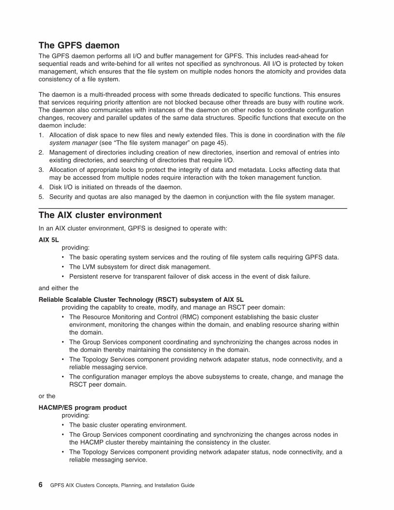
The GPFS daemonThe GPFS daemon performs all I/O and buffer management for GPFS. This includes read-ahead forsequential reads and write-behind for all writes not specified as synchronous. All I/O is protected by tokenmanagement, which ensures that the file system on multiple nodes honors the atomicity and provides dataconsistency of a file system.
The daemon is a multi-threaded process with some threads dedicated to specific functions. This ensuresthat services requiring priority attention are not blocked because other threads are busy with routine work.The daemon also communicates with instances of the daemon on other nodes to coordinate configurationchanges, recovery and parallel updates of the same data structures. Specific functions that execute on thedaemon include:
1. Allocation of disk space to new files and newly extended files. This is done in coordination with the filesystem manager (see “The file system manager” on page 45).
2. Management of directories including creation of new directories, insertion and removal of entries intoexisting directories, and searching of directories that require I/O.
3. Allocation of appropriate locks to protect the integrity of data and metadata. Locks affecting data thatmay be accessed from multiple nodes require interaction with the token management function.
4. Disk I/O is initiated on threads of the daemon.
5. Security and quotas are also managed by the daemon in conjunction with the file system manager.
The AIX cluster environmentIn an AIX cluster environment, GPFS is designed to operate with:
AIX 5Lproviding:
v The basic operating system services and the routing of file system calls requiring GPFS data.
v The LVM subsystem for direct disk management.
v Persistent reserve for transparent failover of disk access in the event of disk failure.
and either the
Reliable Scalable Cluster Technology (RSCT) subsystem of AIX 5Lproviding the capablity to create, modify, and manage an RSCT peer domain:
v The Resource Monitoring and Control (RMC) component establishing the basic clusterenvironment, monitoring the changes within the domain, and enabling resource sharing withinthe domain.
v The Group Services component coordinating and synchronizing the changes across nodes inthe domain thereby maintaining the consistency in the domain.
v The Topology Services component providing network adapater status, node connectivity, and areliable messaging service.
v The configuration manager employs the above subsystems to create, change, and manage theRSCT peer domain.
or the
HACMP/ES program productproviding:
v The basic cluster operating environment.
v The Group Services component coordinating and synchronizing the changes across nodes inthe HACMP cluster thereby maintaining the consistency in the cluster.
v The Topology Services component providing network adapater status, node connectivity, and areliable messaging service.
6 GPFS AIX Clusters Concepts, Planning, and Installation Guide

The RSCT peer domain environmentIn an RSCT peer domain environment, a GPFS cluster is a group of RS/6000 machines, Eserver pSeriesmachines, or a mixture of both with uniform disk access enabling concurrent data sharing. The GPFScluster is created from an existing RSCT peer domain. There can only be one GPFS cluster per RSCTpeer domain. Within that GPFS cluster, you may define multiple GPFS nodesets. However, a node mayonly belong to one nodeset. For further information on the RSCT component of AIX 5L and the associatedsubsystems, see the Reliable Scalable Cluster Technology for AIX 5L: RSCT Guide and Reference.
In this environment, the size of your GPFS nodeset is constrained by the type of disk attachment. If any ofthe disks in the file system are SSA disks, your nodeset may consist of up to eight RS/6000 or EserverpSeries machines (the size of the nodeset is constrained by the limitations of the SSA adapter). If thedisks in the file system are purely Fibre Channel, your nodeset may consist of up to 32 RS/6000 orEserver pSeries machines (the size of the nodeset is constrained by the limitations of the GroupServices software). When a GPFS nodeset is being configured, or nodes are being added to or deletedfrom the cluster, GPFS obtains the necessary additional configuration data from the resource classesmaintained by the RSCT peer domain:
1. node number (PeerNode resource class)
2. adapter type (NetworkInterface resource class)
3. IP address (NetworkInterface resource class)
The complete configuration data maintained by GPFS is then stored on the primary, and if specified, thesecondary GPFS cluster data server as designated on the mmcrcluster command (see “GPFS clustercreation considerations” on page 14).
For complete hardware and programming specifications, see “Hardware specifications” on page 9 and“Programming specifications” on page 9.
The HACMP environmentIn the HACMP environment, a GPFS cluster is a group of RS/6000 machines, Eserver pSeriesmachines, or a mixture of both with uniform disk access enabling concurrent data sharing. The GPFScluster is created from an existing HACMP cluster. There can only be one GPFS cluster per HACMPcluster. Within that GPFS cluster, you may define multiple GPFS nodesets. However, a node may onlybelong to one nodeset. For further on the HACMP/ES program product, see the High Availability ClusterMulti-Processing for AIX: Enhanced Scalability Installation and Administration Guide.
In this environment, the size of your GPFS nodeset is constrained by the type of disk attachment. If any ofthe disks in the file system are SSA disks, your nodeset may consist of up to eight RS/6000 or Eserver
Figure 1. An RSCT peer domain environment
Chapter 1. Introducing General Parallel File System 7
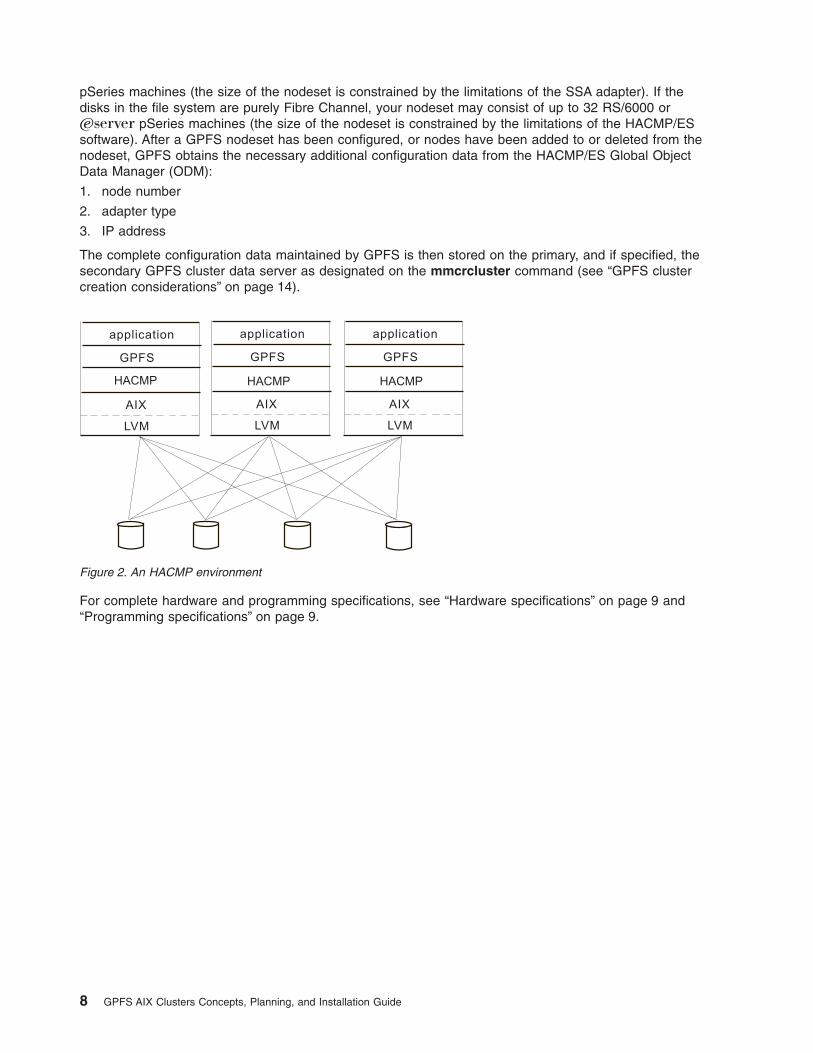
pSeries machines (the size of the nodeset is constrained by the limitations of the SSA adapter). If thedisks in the file system are purely Fibre Channel, your nodeset may consist of up to 32 RS/6000 orEserver pSeries machines (the size of the nodeset is constrained by the limitations of the HACMP/ESsoftware). After a GPFS nodeset has been configured, or nodes have been added to or deleted from thenodeset, GPFS obtains the necessary additional configuration data from the HACMP/ES Global ObjectData Manager (ODM):
1. node number
2. adapter type
3. IP address
The complete configuration data maintained by GPFS is then stored on the primary, and if specified, thesecondary GPFS cluster data server as designated on the mmcrcluster command (see “GPFS clustercreation considerations” on page 14).
For complete hardware and programming specifications, see “Hardware specifications” on page 9 and“Programming specifications” on page 9.
Figure 2. An HACMP environment
8 GPFS AIX Clusters Concepts, Planning, and Installation Guide

Chapter 2. Planning for GPFS
Planning for GPFS includes:
v “Hardware specifications”
v “Programming specifications”
v “Recoverability considerations”
v “Disk considerations” on page 11
v “GPFS cluster creation considerations” on page 14
v “Nodeset configuration considerations” on page 15
v “File system creation considerations” on page 20
Although you can modify your GPFS configuration after it has been set, a little consideration beforeinstallation and initial setup will reward you with a more efficient and immediately useful file system. Duringconfiguration, GPFS requires you to specify several operational parameters that reflect your hardwareresources and operating environment. During file system creation, you have the opportunity to specifyparameters based on the expected size of the files or allow the default values to take effect. Theseparameters define the disks for the file system and how data will be written to them.
Hardware specifications1. An existing IBM Eserver configuration:
v An RSCT peer domain established with the RSCT component of AIX 5L
For information on creating an RSCT peer domain, see the Reliable Scalable Cluster Technology forAIX 5L: RSCT Guide and Reference
v An HACMP cluster established with the HACMP/ES program product
For information on creating an HACMP cluster, see the High Availability Cluster Multi-Processing forAIX: Enhanced Scalability Installation and Administration Guide.
2. Enough disks to contain the file system (see “Disk considerations” on page 11).
3. An IP network of sufficient network bandwidth (minimum of 100Mb per second).
Programming specifications1. AIX 5L Version 5 Release 1 (5765-E61) with IY30258, or later modifications
2. For a GPFS cluster type hacmp, HACMP/ES version 4.4.1 (5765-E54), or later modifications
Recoverability considerationsSound file system planning includes considering replication as well as structuring your data so informationis not vulnerable to a single point of failure. GPFS provides you with parameters that enable you to createa highly available file system with fast recoverability from failures. At the file system level, the metadataand data replication parameters are set (see “File system recoverability parameters” on page 22). At thedisk level when preparing disks for use with your file system, you can specify disk usage and failure grouppositional parameters to be associated with each disk (see “Logical volume creation considerations” onpage 11).
Additionally, GPFS provides several layers of protection against failures of various types:
1. “Node failure” on page 10
2. “Disk failure” on page 10
3. “Making your decision” on page 10
© Copyright IBM Corp. 2002 9

Node failureThis basic layer of protection covers the failure of file system nodes and is provided by Group Services.When an inoperative node is detected by Group Services, GPFS fences it out using environment-specificsubsystems (see Disk fencing). This prevents any write operations that might interfere with recovery.
File system recovery from node failure should not be noticeable to applications running on other nodes,except for delays in accessing objects being modified on the failing node. Recovery involves rebuildingmetadata structures, which may have been under modification at the time of the failure. If the failing nodeis the file system manager for the file system, the delay will be longer and proportional to the activity onthe file system at the time of failure, but no administrative intervention will be needed.
During node failure situations, if multi-node quorum is in effect, quorum needs to be maintained in order torecover the failing nodes. If multi-node quorum is not maintained due to node failure, GPFS restarts on allnodes, handles recovery, and attempts to achieve quorum again.
Disk failureThe most common reason why data becomes unavailable is disk failure with no redundancy. In the eventof disk failure, GPFS discontinues use of the disk and awaits its return to an available state. You canguard against loss of data availability from such failures by setting the GPFS recoverability parameters(replication, disk usage, and failure group designations) either alone or in conjunction with one of theseenvironment specific methods to maintain additional copies of files.
One means of data protection is the use of a RAID/Enterprise Storage Subsystem (ESS) controller, whichmasks disk failures with parity disks. An ideal configuration is shown in Figure 3, where a RAID/ESScontroller is multi-tailed to each node in the nodeset.
Making your decisionEach method of data protection has its cost, whether it be the installation of additional hardware or theconsumption of large amounts of disk space. If your configuration consists of:
v SSA disks and you have greater than two nodes in the GPFS cluster, GPFS replication is the only dataprotection available to you.
v SSA disks with either one or two nodes, you can use both SSA RAID and GPFS replication.
v Fibre Channel disks with any number of nodes, you can use both RAID and GPFS replication.
Figure 3. RAID/ESS Controller multi-tailed to each node
10 GPFS AIX Clusters Concepts, Planning, and Installation Guide

Disk considerationsYou may have up to 1024 external shared disks or disk arrays with the adapters configured to allow eachdisk connectivity to each node in the nodeset. No disk can be larger than 1 TB.
Proper planning for your disk subsystem includes determining:
v Sufficient disks to meet the expected I/O load
v Sufficient connectivity (adapters and buses) between disks
Disks can be attached using:
v SSA
v Fibre Channel
v Enterprise Storage Server™ (ESS) in either Subsystem Device Driver (SDD) or non-SDD mode
The actual number of disks in your system may be constrained by products other than GPFS which youhave installed. Refer to individual product documentation for support information.
Disk considerations include:
v “Disk fencing”
v “Logical volume creation considerations”
Disk fencingIn order to preserve data integrity in the event of certain system failures, GPFS will fence a node that isdown from the file system until it returns to the available state. Depending upon the types of disk you areusing, there are three possible ways for the fencing to occur:
SSA fencingSSA disks
SCSI-3 persistent reserveFor a list of GPFS supported persistent reserve devices, see the Frequently Asked Questions atwww.ibm.com/servers/eserver/clusters/library/
disk leasingA GPFS specific fencing mechanism for disks which do not support either SSA fencing or SCSI-3persistent reserve.
Single-node quorum is only supported when disk leasing is not in effect. Disk leasing is activated if anydisk in any file system in the nodeset is not using SSA fencing or SCSI-3 persistent reserve.
Logical volume creation considerationsYou must prepare each physical disk you intend to use with GPFS as a logical volume. This is done viathe mmcrlv command. Disks are identified to the mmcrlv command by their physical disk device names.
Notes:
1. A PVID must exist on each disk being used by GPFS on each node in the cluster prior to issuing themmcrlv command. If a valid PVID does not exist, the command will fail upon importing the logicalvolume:
a. Verify the existence of a PVID by issuing the lspv command. The system displays informationsimilar to:lspvhdisk3 0020570a72bbb1a0 Nonehdisk4 none None
b. If a PVID does not exist, prior to assigning a PVID you must ensure that the disk is not a memberof a mounted and active GPFS file system. If the disk is a member of an active and mounted
Chapter 2. Planning for GPFS 11

GPFS file system and you issue the chdev command to assign a PVID, there is the possibility youwill experience I/O problems which may result in the file system being unmounted on one or morenodes.
c. To assign a PVID, issue the chdev command:chdev -l hdisk4 -a pv=yes
The system displays information similar to:hdisk4 changed
To determine the PVID assign, issue the lspv command. The system displays information similarto:lspvhdisk3 0020570a72bbb1a0 Nonehdisk4 0022b60ade92fb24 None
2. Single-node quorum is only supported when disk leasing is not in effect. Disk leasing is activated if anydisk in any file system in the nodeset is not using SSA fencing or SCSI-3 persistent reserve.
3. Logical volumes created by the mmcrlv command will:
v Use SCSI-3 persistent reserve on disks which support it or SSA fencing if that is supported by thedisk. Otherwise disk leasing will be used.
v Have bad-block relocation automatically turned off. Accessing disks concurrently from multiplesystems using lvm bad-block relocations could potentially cause conflicting assignments. As a result,software bad-block relocation is turned off allowing the hardware bad-block relocation supplied byyour disk vendor to provide protection against disk media errors.
4. You cannot protect your file system against disk failure by mirroring data at the LVM level. You mustuse GPFS replication or RAID devices to protect your data (see “Recoverability considerations” onpage 9).
5. In an HACMP environment, any disk resources (volume groups and logical volumes) that will be usedby GPFS must not belong to any HACMP/ES resource group. HACMP/ES will not be in control ofthese disk resources and is not responsible for varying them on or off at any time. The responsibility tokeep the disks in the proper state belongs to GPFS in the HACMP environment. For further informationon logical volume concepts, see the AIX 5L System Management Guide: Operating System andDevices.
The mmcrlv command expects as input a file, DescFile, containing a disk descriptor, one per line, foreach of the disks to be processed. Disk descriptors have the format (second and third fields reserved):DiskName:::DiskUsage:FailureGroup
DiskNameThe physical device name of the disk you want to define as a logical volume. This is the /devname for the disk on the node on which the mmcrlv command is issued and can be either anhdisk name or a vpath name for an SDD device. Each disk will be used to create a single volumegroup and a single logical volume.
Disk UsageWhat is to be stored on the disk. metadataOnly specifies that this disk may only be used formetadata, not for data. dataOnly specifies that only data, and not metadata, is allowed on thisdisk. You can limit vulnerability to disk failure by confining metadata to a small number ofconventional mirrored or replicated disks. The default, dataAndMetadata, allows both on the disk.
Note: RAID devices are not well-suited for performing small block writes. Since GPFS metadatawrites are often smaller than a full block, you may find using non-RAID devices for GPFSmetadata better for performance.
12 GPFS AIX Clusters Concepts, Planning, and Installation Guide

FailureGroupA number identifying the failure group to which this disk belongs. All disks that are either attachedto the same adapter have a common point of failure and should therefore be placed in the samefailure group.
GPFS uses this information during data and metadata placement to assure that no two replicas ofthe same block will become unavailable due to a single failure. You can specify any value from -1(where -1 indicates that the disk has no point of failure in common with any other disk) to 4000. Ifyou specify no failure group, the value defaults to -1.
Upon successful completion of the mmcrlv command, these tasks are completed on all nodes in theGPFS cluster:
v For each valid descriptor in the descriptor file, local logical volumes and the local volume groups arecreated.
The logical volume names are assigned according to the convention:
gpfsNNlvwhere NN is a unique non-negative integer not used in any prior logical volume named with thisconvention.
The local volume group component of the logical volume is named according to the same convention:
gpfsNNvgwhere NN is a unique non-negative integer not used in any prior local volume group named withthis convention.
v The physical device or vpath name is replaced with the created logical volume names.
v The local volume groups are imported to all available nodes in the GPFS cluster.
v The DescFile is rewritten to contain the created logical volume names in place of the physical disk orvpath name and all other fields, if specified, are copied without modification. The rewritten diskdescriptor file can then be used as input to the mmcrfs, mmadddisk, or the mmrpldisk commands. Ifyou do not use this file, you must accept the default values or specify these values when creating diskdescriptors for subsequent mmcrfs, mmadddisk, or mmrpldisk commands.
If necessary, the DiskUsage and FailureGroup values for a disk can be changed with the mmchdiskcommand.
Chapter 2. Planning for GPFS 13

GPFS cluster creation considerationsA GPFS cluster is created by issuing the mmcrcluster command. Table 2 details the GPFS clustercreation options on the mmcrcluster command, which options can be changed later by the mmchclustercommand, and what the default values are.
Table 2. GPFS cluster creation options
mmcrcluster mmchcluster default value
“Nodes in your GPFS cluster”
X
To add or deletenodes from the clusteruse mmaddcluster ormmdelclusterrespectively
none
“GPFS cluster data servers”, primary X X none
“GPFS cluster data servers”, secondary X X none
“GPFS cluster type” on page 15X
This cannot bechanged
none
“Remote shell command” on page 15 X X /usr/bin/rsh
“Remote file copy command” on page 15 X X /usr/bin/rcp
Notes:
1. X – indicates the option is available on the command
2. an empty cell – indicates the option in not available on the command
Nodes in your GPFS clusterWhen you create your GPFS cluster you must provide a file containing a list of nodes to be included in thecluster. During creation of your cluster, GPFS copies this information to the GPFS cluster data server.
The file lists one node per line. The hostname or IP address used for a node must refer to the adapterport over which the GPFS daemons communicate. Alias interfaces are not allowed. Use the originaladdress or a name that is resolved by the host command to that original address. You may specify a nodeusing any of these forms:
Format ExampleShort hostname k145n01Long hostname k145n01.kgn.ibm.comIP address 9.119.19.102
You must follow these rules when creating your GPFS cluster:
v A node may only belong to one GPFS cluster at a time.
v The node must be a properly configured member of either your RSCT peer domain or your HACMPcluster.
v The node must be available for the command to be successful. If any of the nodes listed are notavailable when the command is issued, a message listing those nodes is displayed. You must correctthe problem on each node, create a new input file containing the failed nodes only, and reissue themmaddcluster command to add those nodes.
GPFS cluster data serversFrom the nodes included in your GPFS cluster, you must designate one of the nodes as the primary GPFScluster data server on which GPFS configuration information is maintained. It is suggested that you alsospecify a secondary GPFS cluster data server. If your primary server fails and you have not designated a
14 GPFS AIX Clusters Concepts, Planning, and Installation Guide

backup server, the GPFS cluster data is inaccessible and any GPFS administrative command that isissued will fail. Similarly, when the GPFS daemon starts up, at least one of the two GPFS cluster dataserver nodes must be accessible (see “GPFS cluster data” on page 57).
GPFS cluster typeThe only valid GPFS cluster types are either rpd or hacmp. Specifying any other cluster type will causethe mmcrcluster command to fail.
Remote shell commandThe default remote shell command is rsh. This requires that a properly configured /.rhosts file exist in theroot user’s home directory on each node in the GPFS cluster.
If you choose to designate the use of different remote shell command on either the mmcrcluster or themmchcluster command, you must specify the fully qualified pathname for the program to be used byGPFS. You must also ensure:
1. Proper authorization is granted to all nodes in the GPFS cluster.
2. The nodes in the GPFS cluster can communicate without the use of a password.
The remote shell command must adhere to the same syntax form as rsh but may implement an alternateauthentication mechanism.
Remote file copy commandThe default remote file copy program is rcp. This requires that a properly configured /.rhosts file exist inthe root user’s home directory on each node in the GPFS cluster.
If you choose to designate the use of different remote file copy command on either the mmcrcluster orthe mmchcluster command, you must specify the fully qualified pathname for the program to be used byGPFS. You must also ensure:
1. Proper authorization is granted to all nodes in the GPFS cluster.
2. The nodes in the GPFS cluster can communicate without the use of a password.
The remote copy command must adhere to the same syntax form rcp but may implement an alternateauthentication mechanism.
Nodeset configuration considerationsBefore you configure your GPFS nodeset:
1. ensure you have tuned your system (see Chapter 4, “Tuning your system for GPFS”, on page 35).
2. You must first create a GPFS cluster (see “GPFS cluster creation considerations” on page 14).
Configuration involves defining the nodes to be included in the GPFS nodeset and specifying how they willoperate. Your GPFS nodeset is configured by issuing the mmconfig command. Table 3 details theconfiguration options specified on the mmconfig command, which options can be changed later with themmchconfig command, and what the default values are.
Table 3. GPFS configuration options
mmconfig mmchconfig default value
“Nodes in your GPFS nodeset” onpage 16
X
To add or delete nodes ata later time usemmaddnode ormmdelnode respectively
All of the nodes in the GPFScluster.
Chapter 2. Planning for GPFS 15

Table 3. GPFS configuration options (continued)
mmconfig mmchconfig default value
“Nodeset identifier” on page 17X
This cannot be changedonce it is set
An integer value beginning withone and increasing sequentially
“Starting GPFS automatically” onpage 17
X X no
“Path for the storage of dumps” onpage 17
X X /tmp/mmfs
“Quorum” on page 18 X X no
“pagepool” on page 18 X X 20M
“maxFilesToCache” on page 18 X X 1000
“maxStatCache” on page 18 Default valueinitially used
X 4 x maxFilesToCache
“Maximum file system block sizeallowed” on page 19
Default valueinitially used
X 256K
“dmapiEventTimeout” on page 19 X 86400000
“dmapiSessionFailureTimeout” onpage 19
X 0
“dmapiMountTimeout” on page 19 X 60
Notes:
1. X – indicates the option is available on the command
2. an empty cell – indicates the option is not available on the command
Nodes in your GPFS nodesetYou can provide a list of nodes as input to the mmconfig command or allow GPFS to configure all of thenodes in the GPFS cluster. If the disks in your nodeset are SSA or a combination of SSA and FibreChannel, the maximum number of nodes in the nodeset is eight. If your disks are purely Fibre Channel,the maximum number of nodes in a nodeset is 32.
If a node is down or is not a member of the GPFS cluster, the mmconfig command fails. If the node isdown when the mmconfig command is issued, when the nodes comes back up, add it to the nodeset byissuing the mmaddnode command. If the node is not a member of the GPFS cluster (see “GPFS clustercreation considerations” on page 14), you must:
1. Issue the mmaddcluster command.
2. Re-issue the mmconfig command.
Within the GPFS cluster, you may define multiple GPFS nodesets. However, a node may only belong toone nodeset. After a GPFS nodeset has been configured, or nodes have been added to or deleted fromthe nodeset, the information is maintained on the GPFS cluster data server.
When specifying a list of nodes, the name of this list must be specified with the -n option on themmconfig command. The list must contain only one entry per line. Nodes are specified by a NodeNameand may be optionally followed by a use designation:
Node descriptors have the format:
NodeName[:manager | client]
NodeNameThe hostname or IP address used for a node must refer to the communications adapter over
16 GPFS AIX Clusters Concepts, Planning, and Installation Guide

which the GPFS daemons communicate. Alias interfaces are not allowed. Use the original addressor a name that is resolved by the host command to that original address.
You may specify a node using any of these forms:
Format ExampleShort hostname k145n01Long hostname k145n01.kgn.ibm.comIP address 9.119.19.102
manager | clientAn optional use designation.
The designation specifies whether or not the node should be included in the pool of nodes fromwhich the file system manager is chosen (the special functions of the file system managerconsume extra processing time see “The file system manager” on page 45). The default is to nothave the node included in the pool.
In general, small systems (less than 128 nodes) do not need multiple nodes dedicated for the filesystem manager. However, if you are running large parallel jobs, threads scheduled to a nodeperforming these functions may run slower. As a guide, in a large system there should be one filesystem manager node for each GPFS file system.
Nodeset identifierYou can provide a name for the nodeset by using the -C option on the mmconfig command or allowGPFS to assign one. If you choose the identifier, it can be at most eight alphanumeric characters long andmay not be a reserved word or the number zero. If GPFS assigns one, it will be an integer identifierbeginning with the value one and increasing sequentially as nodesets are added. This designation may notbe changed once it is assigned.
The operation of nodesIn deciding how your nodeset will operate, you must consider:
v “Starting GPFS automatically”
v “Path for the storage of dumps”
v “Quorum” on page 18
v “Cache usage” on page 18
v “Maximum file system block size allowed” on page 19
v “DMAPI configuration options” on page 19
Starting GPFS automaticallyYou can configure GPFS to start automatically on all nodes in the nodeset whenever they come up, byspecifying the autoload (-A) option for the mmconfig command. This eliminates the need to start GPFS byissuing the mmstartup command. The default is not to start the daemon automatically.
Path for the storage of dumpsThe default is to store dumps in /tmp/mmfs, however you may specify an alternate path. You may alsospecify no if you do not want to store any dumps.
It is suggested that you create a directory for the storage of dumps as this will contain certain problemdetermination information. This can be a symbolic link to another location if more space can be foundthere. It should not be placed in a GPFS file system as it might not be available should GPFS fail. If aproblem should occur, GPFS may write 200 MB or more of problem determination data into the directory.These files must be manually removed when any problem determination is complete. This should be donepromptly so that a no space condition is not encountered if another failure occurs.
Chapter 2. Planning for GPFS 17

QuorumFor all nodesets consisting of three or more nodes, GPFS quorum is defined as one plus half of thenumber of nodes in the GPFS nodeset (referred to as multi-node quorum). For a two-node nodeset, youhave the choice of allowing multi-node quorum or specifying the -U option on the mmconfig command toindicate the use of a single-node quorum. The specification of single-node quorum allows the remainingnode in a two-node nodeset to continue functioning in the event of the failure of the peer node.
Note: Single-node quorum is only supported when disk leasing is not in effect. Disk leasing is activated ifany disk in any file system in the nodeset is not using SSA fencing or SCSI-3 persistent reserve.
If multi-node quorum is used, quorum needs to be maintained in order to recover the failing nodes. Ifmulti-node quorum is not maintained due to node failure, all GPFS nodes restart, handle recovery, andattempt to achieve quorum again. Therefore, in a three-node system, failure of one node will allowrecovery and continued operation on the two remaining nodes. This is the minimum configuration wherecontinued operation is possible due to the failure of a node. That is, in a two-node system wheresingle-node quorum has not been specified, the failure of one node means both nodes will restart, handlerecovery, and attempt to achieve quorum again.
If single-node quorum is specified, the failure of one node results in GPFS fencing the failing node fromthe disks containing GPFS file system data. The remaining node will continue processing if the fencingoperation was successful. If not, those file systems which could not be completely fenced will beunmounted and attempts to fence the node will continue (in the unlikely event that both nodes end upfenced, see the General Parallel File System for AIX 5L: AIX Clusters Problem Determination Guide andsearch on single-node quorum).
Cache usageGPFS creates a number of cache segments on each node in the nodeset. The amount of cache iscontrolled by three parameters:
pagepoolThe amount of pinned memory reserved for caching data read from disk. This consists mainly offile data, but also includes directory blocks and other file system metadata such as indirect blocksand allocation maps (see Appendix A, “GPFS architecture”, on page 45). pagepool is used forread-ahead and write-behind operations to increase performance, as well as for reuse of cacheddata.
The size of the cache on each node can range from a minimum of 4 MB to a maximum of 512MB. For systems where applications access large files, reuse data, or have a random I/O pattern,increasing the value for pagepool may prove beneficial. This value must be specified with thecharacter M, for example 80M. The default is 20M.
maxFilesToCacheThe total number of different files that can be cached at one time. Every entry in the file cacherequires some pageable memory to hold the content of the file’s inode plus control data structures.This is in addition to any of the file’s data and indirect blocks that might be cached in the pagepool.
The total amount of memory required for inodes and control data structures can be calculated as:
maxFilesToCache × 2.5 KBwhere 2.5 KB = 2 KB + 512 bytes for an inode
Valid values of maxFilesToCache range from 0 to 1,000,000. For systems where applications usea large number of files, of any size, increasing the value for maxFilesToCache may provebeneficial (this is particularly true for systems where a large number of small files are accessed).The value should be large enough to handle the number of concurrently open files plus allowcaching of recently used files. The default value is 1000.
18 GPFS AIX Clusters Concepts, Planning, and Installation Guide
maxStatCacheThis parameter sets aside additional pageable memory to cache attributes of files that are notcurrently in the regular file cache. This is useful to improve the performance of both the systemand GPFS stat( ) calls for applications with a working set that does not fit in the regular file cache.
The memory occupied by the stat cache can be calculated as:
maxStatCache × 176 bytes
Valid values of maxStatCache range from 0 to 1,000,000. For systems where applications test theexistence of files, or the properties of files, without actually opening them (as backup applicationsdo), increasing the value for maxStatCache may prove beneficial. The default value is:
4 × maxFilesToCache
The total amount of memory GPFS uses to cache file data and metadata is arrived at by adding pagepoolto the amount of memory required to hold inodes and control data structures (maxFilesToCache × 2.5KB), and the memory for the stat cache (maxStatCache × 176 bytes) together. The combined amount ofmemory to hold inodes, control data structures, and the stat cache is limited to 50% of the physicalmemory. With an inode size of 512 bytes, the default 4-to-1 ratio of maxStatCache to maxFilesToCachewould result in a maximum 250,000 stat cache entries and 65,000 file cache entries.
During configuration, you can specify the maxFilesToCache, maxStatCache, and pagepool parametersthat control how much cache is dedicated to GPFS. These values can be changed later, so experimentwith larger values to find the optimum cache size that improves GPFS performance without affecting otherapplications.
The mmchconfig command can be used to change the values of maxFilesToCache, maxStatCache,and pagepool. The pagepool parameter is the only one of these parameters that may be changed whilethe GPFS daemon is running. A pagepool change occurs immediately when using the -i option on themmchconfig command. Changes to the other values are effective only after the daemon is restarted.
Maximum file system block size allowedThe valid values for the maximum block size for file systems to be created for the nodeset are 16 KB, 64KB, 256 KB, 512 KB, and 1024 KB (1 MB is also acceptable). After you have configured GPFS, anyattempt to create a file system with a block size larger than the maximum block size will fail. See “Filesystem sizing” on page 21 for a discussion of block size values when creating a file system before youmake a decision on setting the maximum block size allowed.
DMAPI configuration optionsFor a discussion of the DMAPI configuration options, see the General Parallel File System for AIX 5L: AIXClusters Data Management API Guide:
v dmapiEventTimeout
v dmapiSessionFailureTimeout
v dmapiMountTimeout
A sample nodeset configurationTo create a nodeset with these configuration options, allowing all other values to default:
/u/gpfsadmin/nodesGPFS1the file containing the list of 32 nodes to be included in the nodeset
-A Automatically start the GPFS daemon when the nodes come up
set1 the nodeset identifier
Chapter 2. Planning for GPFS 19

-p 100Mpagepool of 100 MB
Issue the command:mmconfig -n /u/gpfsadmin/nodesGPFS1 -A -C set1 -p 100M
To confirm the nodeset configuration, enter:mmlsconfig -C set1
The system displays information similar to:Configuration data for nodeset set1:------------------------------------clusterType rpdcomm_protocol TCPmultinode yesautoload yesuseSingleNodeQuorum nopagepool 100Mgroup Gpfs.set1recgroup GpfsRec.set1
File systems in nodeset set1:-----------------------------(none)
File system creation considerationsFile system creation involves anticipating usage within the file system and considering your hardwareconfigurations. Your GPFS file system is created by issuing the mmcrfs command. Table 4 details the filesystem creation options specified on the mmcrfs command, which options can be changed later with themmchfs command, and what the default values are.
Table 4. File system creation options
mmcrfs mmchfs default value
“Automatic mount” on page 21 X X yes
“Estimated node count” on page 21X
this value cannot bechanged
32
“Block size” on page 21X
this value cannot bechanged
256K
“Maximum number of files” on page 22 X X file system size/1 MB
Default metadata replicas, see “Filesystem recoverability parameters” onpage 22
X X 1
Maximum metadata replicas, see “Filesystem recoverability parameters” onpage 22
Xthis value cannot bechanged
1
Default data replicas, see “File systemrecoverability parameters” on page 22
X X 1
Maximum data replicas, see “Filesystem recoverability parameters” onpage 22
Xthis value cannot bechanged
1
“Automatic quota activation” onpage 23
X X no
“Disk verification” on page 24 X yes
20 GPFS AIX Clusters Concepts, Planning, and Installation Guide

Table 4. File system creation options (continued)
mmcrfs mmchfs default value
“Enable DMAPI” on page 24 X X no
“Mountpoint directory” on page 24 X X none
“Device name of the file system” onpage 25
Xthis attribute cannot bechanged
none
“Disks for the file system” on page 25
X
use mmadddisk andmmdeldisk respectively toadd or delete disks from thefile system
none
“Nodeset to which the file systembelongs” on page 25
X Xthe nodeset from which themmcrfs command is issued
Notes:
1. X – indicates the option is available on the command
2. an empty cell – indicates the option is not available on the command
Automatic mountWhether or not to automatically mount a file system when the GPFS daemon starts may be specified atfile system creation by using the -A option on the mmcrfs command or changed at a later time by usingthe -A option on the mmchfs command. The default is to have the file system automatically mounted,assuring file system availability whenever the system and disks are up.
Estimated node countThe estimated number of nodes that will mount the file system may be specified at file system creation byusing the -n option on the mmcrfs command or allowed to default to 32.
When creating a GPFS file system, over estimate the number of nodes that will mount the file system.This input is used in the creation of GPFS data structures that are essential for achieving the maximumdegree of parallelism in file system operations (see Appendix A, “GPFS architecture”, on page 45).Although a larger estimate consumes a bit more memory, insufficient allocation of these data structurescan limit node ability to process certain parallel requests efficiently, such as the allotment of disk space toa file. If you cannot anticipate the number of nodes, allow the default value to be applied. Specify a largernumber if you expect to add nodes, but avoid wildly overestimating as this can affect buffer operations.This value cannot be changed later.
File system sizing
Before creating a file system, consider how much data will be stored and how great the demand for thefiles in the system will be. Each of these factors can help you to determine how much disk resource todevote to the file system, which block size to choose, where to store data and metadata, and how manyreplicas to maintain.
Block sizeThe size of data blocks in a file system may be specified at file system creation by using the -B option onthe mmcrfs command or allowed to default to 256 KB. This value cannot be changed without recreatingthe file system.
GPFS offers five block sizes for file systems: 16 KB, 64 KB, 256 KB, 512 KB, and 1024 KB. This valueshould be specified with the character K, for example 512K. You should choose the block size based onthe application set that you plan to support and if you are using RAID hardware:
Chapter 2. Planning for GPFS 21

v The 256 KB block size is the default block size and normally is the best block size for file systems thatcontain large files accessed in large reads and writes.
v The 16 KB block size optimizes use of disk storage at the expense of large data transfers.
v The 64 KB block size offers a compromise. It makes more efficient use of disk space than 256 KB whileallowing faster I/O operations than 16 KB.
v The 512 KB and 1024 KB block size may be more efficient if data accesses are larger than 256 KB.
If you plan to use SSA RAID devices in your file system, a larger block size may be more effective andhelp you to avoid the penalties involved in small block write operations to RAID devices. For example,in a RAID configuration utilizing 4 data disks and 1 parity disk (a 4+P configuration), which utilizes a 64KB stripe size, the optimal file system block size would be 256 KB (4 data disks × 64 KB stripe size =256 KB). A 256 KB block size would result in a single data write that encompassed the 4 data disksand a parity write to the parity disk. If a block size smaller than 256 KB, such as 64 KB, was used,write performance would be degraded. A 64 KB block size would result in a single disk writing 64 KBand a subsequent read from the three remaining disks in order to compute the parity that is then writtento the parity disk. The extra read degrades performance.
The maximum GPFS file system size that can be mounted is limited by the control structures in memoryrequired to maintain the file system. These control structures, and consequently the maximum mounted filesystem size, are a function of the block size of the file system.
v If your file systems have a 16 KB block size, you may have one or more file systems with a total size of1 TB mounted.
v If your file systems have a 64 KB block size, you may have one or more file systems with a total size of10 TB mounted.
v If your file systems have a 256 KB or greater block size, you may have file systems mounted with atotal size of not greater than 200 TB where no single file system exceeds 100 TB.
Fragments and subblocks: GPFS divides each block into 32 subblocks. Files smaller than one blocksize are stored in fragments, which are made up of one or more subblocks. Large files are stored in anumber of full blocks plus zero or more subblocks to hold the data at the end of the file.
The block size is the largest contiguous amount of disk space allocated to a file and therefore the largestamount of data that can be accessed in a single I/O operation. The subblock is the smallest unit of diskspace that can be allocated. For a block size of 256 KB, GPFS reads as much as 256 KB of data in asingle I/O operation and small files can occupy as little as 8 KB of disk space. With a block size of 16 KB,small files occupy as little as 512 bytes of disk space (not counting the inode), but GPFS is unable to readmore than 16 KB in a single I/O operation.
Maximum number of filesThe maximum number of files in a file system may be specified at file system creation by using the -Noption on the mmcrfs command or changed at a later time by using the -F option on the mmchfscommand. This value defaults to the size of the file system at creation divided by 1 MB and cannot exceedthe architectural limit of 256 million.
These options limit the maximum number of files that may actively exist within the file system. However,the maximum number of files in the file system is never allowed to consume all of the file system spaceand is thus restricted by the formula:
maximum number of files = (total file system space / 2) / (inode size + subblock size)
File system recoverability parametersThe metadata (inodes, directories, and indirect blocks) and data replication parameters are set at the filesystem level and apply to all files. They are initially set for the file system when issuing the mmcrfs
22 GPFS AIX Clusters Concepts, Planning, and Installation Guide

command. They can be changed for an existing file system using the mmchfs command, butmodifications only apply to files subsequently created. To apply the new replication values to existing filesin a file system, issue the mmrestripefs command.
Metadata and data replication are specified independently. Each has a default replication factor of 1 (noreplication) and a maximum replication factor. Although replication of metadata is less costly in terms ofdisk space than replication of file data, excessive replication of metadata also affects GPFS efficiencybecause all metadata replicas must be written. In general, more replication uses more space.
Default metadata ReplicasThe default number of copies of metadata for all files in the file system may be specified at file systemcreation by using the -m option on the mmcrfs command or changed at a later time by using the -moption on the mmchfs command. This value must be equal to or less than MaxMetadataReplicas, andcannot exceed the number of failure groups with disks that can store metadata. The allowable values are1 or 2, with a default of 1.
Maximum metadata replicasThe maximum number of copies of metadata for all files in the file system may be specified at file systemcreation by using the -M option on the mmcrfs command or allowed to default to 1. The allowable valuesare 1 or 2, but it cannot be lower than DefaultMetadataReplicas. This value can only be overridden by asystem call when the file has a length of 0.
Default data replicasThe default replication factor for data blocks may be specified at file system creation by using the -r optionon the mmcrfs command or changed at a later time by using the -r option on the mmchfs command. Thisvalue must be equal to or less than MaxDataReplicas, and the value cannot exceed the number of failuregroups with disks that can store data. The allowable values are 1 and 2, with a default of 1.
Maximum data replicasThe maximum number of copies of data blocks for a file may be specified at file system creation by usingthe -R option on the mmcrfs command or allowed to default to 1. The allowable values are 1 and 2, butcannot be lower than DefaultDataReplicas. This value can only be overridden by a system call when thefile has a length of 0.
Automatic quota activationWhether or not to automatically activate quotas when the file system is mounted may be specified at filesystem creation by using the -Q option on the mmcrfs command or changed at a later time by using the-Q option on the mmchfs command. After the file system has been mounted, quota values are establishedby issuing the mmedquota command and activated by issuing the mmquotaon command. The default isto not have quotas activated.
The GPFS quota system helps you to control the allocation of files and data blocks in a file system. GPFSquotas can be defined for individual users or groups of users. Quotas should be installed by the systemadministrator if control over the amount of space used by the individual users or groups of users isdesired. When setting quota limits for a file system, the system administrator should consider thereplication factors of the file system. GPFS quota management takes replication into account whenreporting on and determining if quota limits have been exceeded for both block and file usage. In a filesystem which has either type of replication set to a value of two, the values reported on by both themmlsquota and the mmrepquota commands are double the value reported by the ls command.
GPFS quotas operate with three parameters that you can explicitly set using the mmedquota andmmdefedquota commands:
1. Soft limit
2. Hard limit
3. Grace period
Chapter 2. Planning for GPFS 23

The soft limits define levels of disk space and files below which the user or group can safely operate. Thehard limits define the maximum disk space and files the user or group can accumulate. Specify hard andsoft limits for disk space in units of kilobytes (k or K) or megabytes (m or M). If no suffix is provided, thenumber is assumed to be in bytes.
The grace period allows the user or group to exceed the soft limit for a specified period of time (the defaultperiod is one week). If usage is not reduced to a level below the soft limit during that time, the quotasystem interprets the soft limit as the hard limit and no further allocation is allowed. The user or group canreset this condition by reducing usage enough to fall below the soft limit.
Default quotasApplying default quotas ensures all new users or groups of users of the file system will have minimumquota limits established. If default quota values for a file system are not enabled, a new user or group hasa quota value of zero which establishes no limit to the amount of space they can use. Default quotas maybe set for a file system only if the file system was created with the -Q yes option on the mmcrfs orupdated with the -Q option on the mmchfs command. Default quotas may then be enabled for the filesystem by issuing the mmdefquotaon command and default values established by issuing themmdefedquota command.
Quota system filesThe quota system maintains usage and limits data in the user.quota and group.quota files that reside inthe root directories of GPFS file systems. These files are built with the information provided in themmedquota and mmdefedquota commands. These files are updated through normal allocationoperations throughout the file system and when the mmcheckquota command is issued. The user.quotaand group.quota files are readable by the mmlsquota and mmrepquota commands.
These files are also read when mounting a file system with quotas enabled. If these files are not availablewhen mounting the file system, new quota files are created. If the files exist in the file system’s rootdirectory, there are 3 possible situations:
1. The files contain quota information and the user wants these files to be used.
2. The files contain quota information, however, the user wants different files to be used.
In order to specify the usage of different files, the mmcheckquota command must be issued prior tothe mount of the file system.
3. The files do not contain quota information, but are used during the mount of the file system. In thiscase the mount will fail and appropriate error messages will be displayed. See the General ParallelFile System for AIX 5L: AIX Clusters Problem Determination Guide for further information regardingmount failures.
Disk verificationWhen you create your file system, you may check to ensure the disks you are specifying do not alreadybelong to an existing file system by using the -v option on the mmcrfs command. The default is to verifydisk usage. You should only specify no when you want to reuse disks that are no longer needed for anexisting GPFS file system. To determine which disks are no longer in use by any file system, issue themmlsgpfsdisk -F command.
Enable DMAPIWhether or not the file system can be monitored and managed by the GPFS Data Management API(DMAPI) may be specified at file system creation by using the -z option on the mmcrfs command orchanged at a later time by using the -z option on the mmchfs command. The default is not to enableDMAPI for the file system. For further information on DMAPI for GPFS, see General Parallel File Systemfor AIX 5L: AIX Clusters Data Management API Guide.
Mountpoint directoryThere is no default mountpoint directory supplied for the file system. You must specify the directory.
24 GPFS AIX Clusters Concepts, Planning, and Installation Guide

Device name of the file systemSpecify a device name for your file system that is unique across all GPFS nodesets and is not an existingentry in /dev. The device name need not be fully qualified. fs0 is as acceptable as /dev/fs0. The filesystem name cannot be changed at a later time.
Disks for the file systemPrior to issuing the mmcrfs command you must decide if you will:
1. Create new disks via the mmcrlv command.
2. Select disks previously created by the mmcrlv command, but no longer in use in any file system.Issue the mmlsgpfsdisk -F command to display the available disks.
3. Use the rewritten disk descriptor file produced by the mmcrlv command or create a new list of diskdescriptors. When using the rewritten file, the Disk Usage and Failure Group specifications will remainthe same as specified on the mmcrlv command.
When issuing the mmcrfs command you may either pass the disk descriptors in a file or provide a list ofdisk descriptors to be included. The file eliminates the need for command line entry of these descriptorsusing the list of DiskDescs. You may use the rewritten file created by the mmcrlv command, or createyour own file. When using the file rewritten by the mmcrlv command, the Disk Usage and Failure Groupvalues are preserved. Otherwise, you must specify a new value or accept the default. You can use anyeditor to create such a file to save your specifications. When providing a list on the command line, eachdescriptor is separated by a semicolon (;) and the entire list must be enclosed in quotation marks (’ or ″).The current maximum number of disk descriptors that can be defined for any single file system is 1024.
Each disk descriptor must be specified in the form (second and third fields reserved):DiskName:::DiskUsage:FailureGroup
DiskName
You must specify the logical volume name. For details on creating a logical volume, see “Logicalvolume creation considerations” on page 11. To use an existing logical volume in the file system,only the logical volume name need be specified in the disk descriptor. The disk name must be setup the same on all nodes in the nodeset.
Disk UsageSpecifies what is to be stored on the disk. Specify one or accept the default:
v dataAndMetadata (default)
v dataOnly
v metadataOnly
Failure GroupA number identifying the failure group to which this disk belongs. You can specify any value from-1 (where -1 indicates that the disk has no point of failure in common with any other disk) to 4000.If you do not specify a failure group, the value defaults to the -1. GPFS uses this informationduring data and metadata placement to assure that no two replicas of the same block are writtenin such a way as to become unavailable due to a single failure. All disks that are attached to thesame disk adapter, should be placed in the same failure group.
Nodeset to which the file system belongsIf you do not specify a particular nodeset for the file system to belong to, by default it will belong to thenodeset from which the mmcrfs command was issued. You may move a file system to a different nodesetby issuing the mmchfs command. When moving a file system, before the file system is mounted on thetarget nodeset, it must have the same disk connectivity as the original nodeset.
Chapter 2. Planning for GPFS 25
||
|||

A sample file system creationTo create a file system with these configuration options, allowing all other values to default:
A Automatically mount the file system when the GPFS daemon starts.
R Default maximum number of copies of data blocks for the file.
M Default maximum number of copies of inodes, directories, and indirect blocks for the file.
v Verify the specified disks do not belong to an existing file system.
Issue the command:mmcrfs /fs3 fs3 -F crlvdd3 -A yes -R 2 -M 2 -v yes
The system displays information similar to:GPFS: 6027-531 The following disks of fs3 will be formatted on node k154n06.kgn.ibm.com:
gpfs33lv: size 8880128 KBGPFS: 6027-540 Formatting file system ... Creating Inode File Creating Allocation Maps
Clearing Inode Allocation Map Clearing Block Allocation Map Flushing Allocation Maps GPFS:6027-572 Completed creation of file system /dev/fs3.mmcrfs: 6027-1371 Propagating the changes to all affected nodes. This is an asynchronous process.
To confirm the file system configuration, issue the command:mmlsfs fs3
The system displays information similar to:flag value description---- ----------------- -------------------------------------------------s roundRobin Stripe method-f 8192 Minimum fragment size in bytes-i 512 Inode size in bytes-I 16384 Indirect block size in bytes-m 1 Default number of metadata replicas-M 2 Maximum number of metadata replicas-r 1 Default number of data replicas-R 2 Maximum number of data replicas-a 1048576 Estimated average file size-n 32 Estimated number of nodes that will mount file system-B 262144 Block size-Q none Quotas enforced
none Default quotas enabled-F 33792 Maximum number of inodes-V 6.00 File system version. Highest supported version: 6.00-z no Is DMAPI enabled?-d gpfs33lv Disks in file system-A yes Automatic mount option-C set1 GPFS nodeset identifier-E no Exact mtime default mount option-S no Suppress atime default mount option-o none Additional mount options
26 GPFS AIX Clusters Concepts, Planning, and Installation Guide

Part 2. Preparing your system for GPFS
Part 2 provides information on:
v Chapter 3, “Installing GPFS”, on page 29
v Chapter 4, “Tuning your system for GPFS”, on page 35
v Chapter 5, “Migration, coexistence, and compatibility”, on page 37
v Chapter 6, “Permanently uninstalling GPFS”, on page 41
© Copyright IBM Corp. 2002 27

28 GPFS AIX Clusters Concepts, Planning, and Installation Guide

Chapter 3. Installing GPFS
It is suggested you read Chapter 2, “Planning for GPFS”, on page 9 before getting started.
Do not attempt to install GPFS if you do not have the correct hardware (“Hardware specifications” on page9) and software (“Programming specifications” on page 9) prerequisites installed on your system (see“Verifying the level of prerequisite software” on page 30) .
Ensure that the PATH environment variable on each node includes:
v /usr/lpp/mmfs/bin
The installation process includes:
1. “Electronic license agreement”
2. “Files to ease the installation process”
3. “Verify there is no conflicting software installed”
4. “Verifying the level of prerequisite software” on page 30
5. “Installation procedures” on page 31
6. “Verifying the GPFS installation” on page 33
7. “What’s next after completing the installation of GPFS” on page 33
Electronic license agreementBeginning with GPFS 2.1, software license agreements are shipped and viewable electronically. If aproduct has an electronic license agreement, it must be accepted before software installation can continue.
For additional software package installations, the installation cannot occur unless the appropriate licenseagreements are accepted. When using the installp command, use the -Y flag to accept licenses and the-E flag to view license agreement files on the media.
Files to ease the installation processCreation of a file that contains all of the nodes in your GPFS cluster prior to the installation of GPFS willbe useful during the installation process. Using either hostnames or IP addresses when constructing thefile will allow you to use this information when creating your cluster via the mmcrcluster command.
Create a file listing the nodes which will be running GPFS, one per line:/tmp/gpfs.allnodesk145n01.dpd.ibm.comk145n02.dpd.ibm.comk145n03.dpd.ibm.comk145n04.dpd.ibm.comk145n05.dpd.ibm.comk145n06.dpd.ibm.comk145n07.dpd.ibm.comk145n08.dpd.ibm.com
Verify there is no conflicting software installedWhen installing GPFS for the first time, you must verify there is no conflicting software already installed.Due to common components shared by GPFS, IBM Multi-Media Server, and IBM Video Charger, thekernel extensions for GPFS cannot coexist with these products on the same system. If either of theseproducts exist on your system, you will have to remove them in order to successfully install GPFS. Runthis short piece of code:
© Copyright IBM Corp. 2002 29

#!/usr/bin/kshfor node in $(cat /tmp/gpfs.allnodes)dorsh $node lslpp -l "mmfs.*"done
If any mmfs filesets exist, you have either one or both of the IBM Multi-Media Server and IBM VideoCharger products installed and you should remove them.
Verifying the level of prerequisite softwareIt is necessary to verify you have the correct levels of the prerequisite software installed. If the correctlevel of prerequisite software is not installed, see the appropriate installation manual before proceedingwith your GPFS installation:
Note: When installing AIX from system images created with the mksysb command, duplicate node idsmay be generated on those nodes. The lsnodeid (available in /usr/sbin/rsct/bin) has beenprovided for you to verify whether or not node ids are duplicated within the cluster. If a duplicatenode id is found, go to the RSCT Resource Monitoring and Control README located atwww.ibm.com/servers/eserver/clusters/library and follow the procedure to generate unique node ids.
1. AIX 5L Version 5.1 with APAR IY33002, or later modifications:lslpp -l bos.mp
2. For a GPFS cluster type rpd, the following RSCT file sets must be installed on each node in the GPFScluster:lslpp -l rsct*
The system displays information similar to:Fileset Level State Description----------------------------------------------------------------------------Path: /usr/lib/objreposrsct.basic.rte 2.2.1.20 COMMITTED RSCT Basic Functionrsct.compat.basic.rte 2.2.1.20 COMMITTED RSCT Event Management Basic Functionrsct.compat.clients.rte 2.2.1.20 COMMITTED RSCT Event Management Client Functionrsct.core.auditrm 2.2.1.20 COMMITTED RSCT Audit Log Resource Managerrsct.core.errm 2.2.1.20 COMMITTED RSCT Event Response Resource Managerrsct.core.fsrm 2.2.1.20 COMMITTED RSCT File System Resource Managerrsct.core.hostrm 2.2.1.20 COMMITTED RSCT Host Resource Managerrsct.core.rmc 2.2.1.20 COMMITTED RSCT Resource Monitoring and Controlrsct.core.sec 2.2.1.20 COMMITTED RSCT Securityrsct.core.sr 2.2.1.20 COMMITTED RSCT Registryrsct.core.utils 2.2.1.20 COMMITTED RSCT UtilitiesPath: /etc/objreposrsct.basic.rte 2.2.1.20 COMMITTED RSCT Basic Functionrsct.compat.basic.rte 2.2.1.20 COMMITTED RSCT Event Management Basic Functionrsct.core.rmc 2.2.1.20 COMMITTED RSCT Resource Monitoring and Controlrsct.core.sec 2.2.1.20 COMMITTED RSCT Securityrsct.core.sr 2.2.1.20 COMMITTED RSCT Registryrsct.core.utils 2.2.1.20 COMMITTED RSCT Utilities
3. For a GPFS cluster type hacmp, HACMP/ES Version 4 Release 4.1, or later modifications must beinstalled on each node in the GPFS cluster:lslpp -l cluster*
The system displays information similar to:Fileset Level State Description----------------------------------------------------------------------------Path: /usr/lib/objreposcluster.doc.en_US.es.html 4.4.1.2 COMMITTED HAES Web-based HTML Documentation - U.S. Englishcluster.doc.en_US.es.pdf 4.4.1.1 COMMITTED HAES PDF Documentation - U.S. Englishcluster.doc.en_US.es.ps 4.4.1.0 COMMITTED HAES Postscript Documentation - U.S. English
30 GPFS AIX Clusters Concepts, Planning, and Installation Guide
|||||

cluster.es.client.lib 4.4.1.2 COMMITTED ES Client Librariescluster.es.client.rte 4.4.1.4 COMMITTED ES Client Runtimecluster.es.client.utils 4.4.1.2 COMMITTED ES Client Utilitiescluster.es.clvm.rte 4.4.1.0 COMMITTED ES for AIX Concurrent Accesscluster.es.cspoc.cmds 4.4.1.4 COMMITTED ES CSPOC Commandscluster.es.cspoc.dsh 4.4.1.0 COMMITTED ES CSPOC dshcluster.es.cspoc.rte 4.4.1.2 COMMITTED ES CSPOC Runtime Commandscluster.es.hc.rte 4.4.1.1 COMMITTED ES HC Daemoncluster.es.server.diag 4.4.1.4 COMMITTED ES Server Diagscluster.es.server.events 4.4.1.5 COMMITTED ES Server Eventscluster.es.server.rte 4.4.1.5 COMMITTED ES Base Server Runtimecluster.es.server.utils 4.4.1.5 COMMITTED ES Server Utilitiescluster.msg.En_US.es.client 4.4.1.0 COMMITTED ES Client Messages - U.S. English IBM-850cluster.msg.En_US.es.server 4.4.1.0 COMMITTED ES Server Messages - U.S. English IBM-850cluster.msg.en_US.es.client 4.4.1.0 COMMITTED ES Client Messages - U.S. Englishcluster.msg.en_US.es.server 4.4.1.0 COMMITTED ES Recovery Driver Messages - U.S. EnglishPath: /etc/objreposcluster.es.client.rte 4.4.1.0 COMMITTED ES Client Runtimecluster.es.clvm.rte 4.4.1.0 COMMITTED ES for AIX Concurrent Accesscluster.es.hc.rte 4.4.1.0 COMMITTED ES HC Daemoncluster.es.server.events 4.4.1.0 COMMITTED ES Server Eventscluster.es.server.rte 4.4.1.5 COMMITTED ES Base Server Runtimecluster.es.server.utils 4.4.1.0 COMMITTED ES Server UtilitiesPath: /usr/share/lib/objreposcluster.man.en_US.es.data 4.4.1.0 COMMITTED ES Man Pages - U.S. English
Installation proceduresFollow these steps to install the GPFS software using the installp command. This procedure installsGPFS on one node at a time.
Note: The installation procedures are generalized for all levels of GPFS. Ensure you substitute the correctnumeric value for the modification (m) and fix (f) levels, where applicable. The modification and fixlevel are dependent upon the level of PTF support.
Creating the GPFS directoryOn any node (normally node 1), create a subdirectory in /tmp/gpfslpp with the command:mkdir /tmp/gpfslpp
Then copy the installation images from the CD-ROM to the new directory, using the bffcreate command:bffcreate -qvX -t /tmp/gpfslpp -d /dev/cd0 all
This will place the following GPFS images in the image directory:
1. mmfs.base.usr.3.5.m.f
2. mmfs.gpfs.usr.2.1.m.f
3. mmfs.msg.en_US.usr.3.5.m.f
4. mmfs.gpfsdocs.data.3.5.m.f
Installing the GPFS man pagesThere are two sets of man pages shipped with the GPFS for AIX 5L program product. There is one set forthe PSSP cluster environment and one set for the AIX cluster environment. You should set yourMANPATH environment variable to access the correct set of man pages (see “MANPATH environmentvariable” on page 36).
Note: mmfs.gpfsdocs.data need not be installed on all nodes if man pages are not desired or local filesystem space on the node is minimal.
Chapter 3. Installing GPFS 31

Creating the GPFS installation images1. Make the new image directory the current directory:
cd /tmp/gpfslpp
2. Use the inutoc command to create a .toc file. The .toc file is used by the installp command.inutoc .
3. To view the product README after creating the installation images:installp -l -d . mmfs | more
If you have previously installed GPFS on your system, during the install process you may see messagessimilar to:Some configuration files could not be automatically merged into thesystem during the installation. The previous versions of these fileshave been saved in a configuration directory as listed below. Comparethe saved files and the newly installed files to determine if you needto recover configuration data. Consult product documentation todetermine how to merge the data.
Configuration files which were saved in /lpp/save.config:/var/mmfs/etc/gpfsready/var/mmfs/etc/mmfs.cfg/var/mmfs/etc/mmfsdown.scr/var/mmfs/etc/mmfsup.scr
If you have made changes to any of these files, you will have to reconcile the differences with the newversions of the files in directory /var/mmfs/etc. This does not apply to file /var/mmfs/etc/mmfs.cfg which isautomatically maintained by GPFS.
Installing GPFS on your networkInstall GPFS according to one of the following procedures, depending on whether or not your network hasa shared file system.
Installing on a shared file system network1. Ensure that the image directory is NFS-exported to the system nodes.
Export the local directory, which is not in the /etc/exports file, without restrictions for NFS clients tomount:exportfs -i /tmp/gpfslpp
To display whether or not k145n01 has any exported directories, enter:showmount -e k145n01
The system displays information similar to:export list for k145n01:/tmp/gpfslpp (everyone)
2. On each node, issue a mount command to NFS mount the image directory:mount k145n01:/tmp/gpfslpp /mnt
3. On the first node in the GPFS nodeset, issue an installp command to install GPFS:installp -agXYd /tmp/gpfslpp all
4. To install GPFS on the rest of the nodes individually, issue an installp command on each of thenodes:installp -agXYd /mnt all
32 GPFS AIX Clusters Concepts, Planning, and Installation Guide

Installing on a non-shared file system networkIf the GPFS installation directory is not in a shared network file system: copy the images to each node,from the node that the GPFS installation directory was initially installed on (for example k145n01), asfollows:mkdir /tmp/gpfslpprcp -p k145n01:/tmp/gpfslpp/* /tmp/gpfslpp
Then, install on each node from its local GPFS installation directory:installp -agXdY /tmp/gpfslpp all
Verifying the GPFS installationUse the lslpp command to verify the installation of GPFS filesets on each system node:k145n01:/ # lslpp -l mmfs\*
Output similar to the following should be returned:Fileset Level State Description----------------------------------------------------------------------------
Path: /usr/lib/objreposmmfs.base.cmds 3.5.0.0 COMMITTED GPFS File Manager Commandsmmfs.base.rte 3.5.0.0 COMMITTED GPFS File Managermmfs.gpfs.rte 2.1.0.0 COMMITTED GPFS File Managermmfs.msg.en_US 3.5.0.0 COMMITTED GPFS Server Messages - U.S.
English
Path: /etc/objreposmmfs.base.rte 3.5.0.0 COMMITTED GPFS File Managermmfs.gpfs.rte 2.1.0.0 COMMITTED GPFS File Manager
Path: /usr/share/lib/objreposmmfs.gpfsdocs.data 3.5.0.0 COMMITTED GPFS Server Manpages
What’s next after completing the installation of GPFSNow that you have successfully installed GPFS, you must (in the specified order):
1. Tune your system prior to configuring GPFS (see Chapter 4, “Tuning your system for GPFS”, onpage 35).
2. Create a GPFS cluster, see “GPFS cluster creation considerations” on page 14.
3. Configure your GPFS nodeset by issuing the mmconfig command (see “Nodeset configurationconsiderations” on page 15).
4. Start GPFS by issuing the mmstartup command (see the General Parallel File System for AIX 5L: AIXClusters Administration and Programming Reference).
5. Create your file systems by issuing the mmcrfs command (see “File system creation considerations”on page 20 ).
Chapter 3. Installing GPFS 33

34 GPFS AIX Clusters Concepts, Planning, and Installation Guide

Chapter 4. Tuning your system for GPFS
Before you configure GPFS (see “Nodeset configuration considerations” on page 15), you need toconfigure and tune your system. Values suggested here reflect evaluations made on the hardwareavailable at the time this document was written. For the latest values regarding new hardware, seewww.ibm.com/servers/eserver/pseries/software/sp/gpfs.html.
System configuration settingsThe settings on your system should be applied prior to configuring GPFS. The particular componentswhose configuration settings need to be considered are:
1. “Security”
2. “Topology Services”
3. “Communications I/O”
4. “Disk I/O” on page 36
5. “nofiles” on page 36
6. “MANPATH environment variable” on page 36
SecurityWhen using rcp and rsh for remote communication, a properly configured /.rhosts file must exist in theroot user’s home directory on each node in the GPFS cluster. If you have designated the use of a differentremote communication program on either the mmcrcluster or the mmchcluster, you must ensure:
v Proper authorization is granted to all nodes in the GPFS cluster.
v The nodes in the GPFS cluster can communicate without the use of a password.
If this has not been properly configured, you will get GPFS errors.
Topology ServicesGPFS requires invariant network connections. An adapter with an invariant address is one that cannot beused for IP address takeover operations. The adapter must be part of a network with no service addressesand should not have a standby adapter on the same network. That is, the port on a particular IP addressmust be a fixed piece of hardware that is translated to a fixed network adapter and is monitored for failure.Topology Services should be configured to heartbeat over this invariant address. For information onconfiguring Topology Services:
1. For a cluster type of rpd, see the Reliable Scalable Cluster Technology for AIX 5L: RSCT Guide andReference
2. For a cluster type of hacmp, see the High Availability Cluster Multi-Processing for AIX: EnhancedScalability Installation and Administration Guide.
Communications I/OThe ipqmaxlen network option should be considered when configuring for GPFS. The ipqmaxlenparameter controls the number of incoming packets that can exist on the IP interrupt queue. The default of128 is often insufficient. The recommended setting is 512.no -o ipqmaxlen=512
Since this option must be modified at every reboot, it is suggested it be placed at the end of one of thesystem start-up files, such as the /etc/rc.net shell script. For detailed information on the ipqmaxlenparameter, see the AIX 5L Performance Management Guide.
© Copyright IBM Corp. 2002 35

Disk I/OThe disk I/O option to consider when configuring GPFS and using SSA RAID:
max_coalesceThe max_coalesce parameter of the SSA RAID device driver allows the device driver to coalescerequests which have been broken up to satisfy LVM requirements. This parameter can be criticalwhen using RAID and is required for effective performance of RAID writes. The recommendedsetting is 0x40000 for 4+P RAID.
v To view:lsattr -E -l hdiskX -a max_coalesce
v To set:chdev -l hdiskX -a max_coalesce=0x40000
For further information on the max_coalesce parameter see the AIX 5L Technical Reference: Kernel andSubsystems, Volume 2.
nofilesEnsure that nofiles, the file descriptor limit in /etc/security/limits, is set to -1 (unlimited) on the ControlWorkstation.
MANPATH environment variableMultiple sets of GPFS man pages are shipped with the GPFS for AIX 5L program product. There is oneset for the PSSP cluster environment and one set for the AIX cluster environment. In order to access thecorrect set of man pages for the AIX cluster environment, you must set your MANPATH environmentvariable to include /usr/lpp/mmfs/gpfsdocs/man/aix.
36 GPFS AIX Clusters Concepts, Planning, and Installation Guide

Chapter 5. Migration, coexistence, and compatibility
This chapter contains information to help you migrate your GPFS nodeset:
v “Migrating to GPFS 2.1”
v “Coexistence” on page 39
v “Compatibility” on page 40
Migrating to GPFS 2.1These conventions must be followed when migrating to GPFS 2.1:
v All nodes within a GPFS nodeset must be upgraded to GPFS 2.1 at the same time.
v New file system functions existing in GPFS 2.1 are not usable until you explicitly authorize thesechanges by issuing the mmchfs -V command.
v After completing the migration, before you can use an existing logical volume which was not part of anyGPFS file system at the time of migration, you must:
1. Export the logical volume
2. Recreate the logical volume using the mmcrlv command.
3. Add the logical volume to a file system
v In order to use the 64-bit versions of the GPFS programming interfaces, you must recompile your codeusing the appropriate 64-bit options for your compiler.
v The GPFS Data Management API is only supported in a 32-bit version.
The migration process includes:
v “GPFS nodesets for migration”
v “Staged migration to GPFS 2.1”
v “Full migration to GPFS 2.1” on page 38
v “Reverting to the previous level of GPFS” on page 39
GPFS nodesets for migrationYou have the ability to define more than one GPFS nodeset in the same GPFS cluster (see “Nodesetconfiguration considerations” on page 15). This allows you to create a separate nodeset for testing the newlevel of GPFS code without affecting the main GPFS nodeset running at production level.
Your system should have a minimum of 6 nodes in order to use multiple GPFS nodesets and do a stagedmigration. If you have less than 6 nodes, it is recommended you do a full migration. See “Full migration toGPFS 2.1” on page 38.
Staged migration to GPFS 2.1In a staged migration you will first install the new level of GPFS only on a small subset of nodes as a testnodeset. Once you are satisfied with the new code, you can upgrade the rest of the nodes.
A staged migration to the new level of GPFS consists of the following steps:
1. Decide which nodes will be used to test the new level of GPFS. It is recommended that you use atleast three nodes for this purpose. Create a file, /tmp/gpfs.nodes containing the list of hostnames,one per line, of the nodes to be used in the migration.
The hostname or IP address must refer to the communications adapter. Alias interfaces are notallowed. Use the original address or a name that is resolved by the host command to that originaladdress. You may specify a node using any of these forms:
© Copyright IBM Corp. 2002 37

Format ExampleShort hostname k145n01Long hostname k145n01.kgn.ibm.comIP address 9.119.19.102
2. Stop GPFS on all the nodes in the test nodeset:mmshutdown -W /tmp/gpfs.nodes
3. Using the mmdelnode command, delete the nodes in the test nodeset from the main GPFS nodeset.See the General Parallel File System for AIX 5L: AIX Clusters Administration and ProgrammingReference and search on deleting nodes from a GPFS nodeset.
4. Copy the install images as described in “Creating the GPFS directory” on page 31. Install the newcode on the nodes in the test nodeset. The install process will not affect your main GPFS nodeset.See Chapter 3, “Installing GPFS”, on page 29.
5. Reboot all the nodes in the test nodeset. This is required so the kernel extensions can be replaced.
6. Using the mmconfig command, create the test nodeset. See “Nodeset configuration considerations”on page 15.
7. Using the mmcrfs command, create a file system for testing the new level of GPFS (see “File systemcreation considerations” on page 20).
Notes:
a. If you want to use an existing file system, move the file system by issuing the mmchfs commandwith the -C option.
b. If the file system was created under your original level of GPFS, you must explicitly migrate thefile system (mmchfs -V) before you can use the new functions in the latest level of GPFS.Remember you cannot go back once you do this step! Any attempt to mount a migrated filesystem on a back-level GPFS system will be rejected with an error.
See the General Parallel File System for AIX 5L: AIX Clusters Administration and ProgrammingReference for complete information on the GPFS administration commands.
8. Operate with the new level of code for awhile to make sure you want to migrate the rest of the nodes.
If you decide to go back to your original GPFS level, see “Reverting to the previous level of GPFS” onpage 39.
9. Attention: You cannot go back once you do this step! Any attempt to mount a migrated file systemon a back-level GPFS system will be rejected with an error.
Once you have decided to permanently accept the latest level of GPFS, for each of the file systemsthat are in the new nodeset, issue:mmchfs filesystem -V
You may now exploit the new functions in the GPFS code.
10. When you are ready to migrate the rest of the nodes in the main GPFS nodeset:
a. Follow steps 2, 4, 5, and 9.
b. Either delete the file systems from the test nodeset by issuing the mmdelfs command, or movethem to the main GPFS nodeset by issuing the mmchfs command with the -C option.
c. Delete the nodes from the test nodeset by issuing the mmdelnode command and add them tothe main nodeset by issuing the mmaddnode command.
11. Issue the mmlsfs command to verify that the file system has been upgraded to latest level of GPFS.For GPFS 2.1 the -V option should indicate a version level of 6.
12. You may now operate with the new level of GPFS code.
Full migration to GPFS 2.1A full migration to the new GPFS level consists of these steps:
1. Copy the install images to all nodes as described in “Creating the GPFS directory” on page 31.
38 GPFS AIX Clusters Concepts, Planning, and Installation Guide

2. Stop GPFS on all nodes:mmshutdown -a
3. Install the new code on all nodes. See Chapter 3, “Installing GPFS”, on page 29.
4. Reboot all nodes. This is required so the kernel extensions can be replaced.
5. Operate with the new level of code for awhile to make sure you want to permanently migrate.
If you decide to go back to the previous level of GPFS, see “Reverting to the previous level of GPFS”.
6. Attention: Remember you cannot go back once you do this step! Any attempt to mount a migratedfile system on a back-level GPFS system will be rejected with an error.
Once you have decided to permanently accept the latest level of GPFS, for each of the file systems,issue:mmchfs filesystem -V
7. You may now operate with the new level of GPFS code.
Reverting to the previous level of GPFSIf you should decide not to continue the migration to the latest level of GPFS, and you have not issued themmchfs -V command, you may reinstall the back level of GPFS using the following steps:
1. Copy the install images of the back level GPFS code on all affected nodes.
2. Stop GPFS on all affected nodes:mmshutdown -W /tmp/gpfs.nodes
3. If you used a test nodeset for testing the latest level of GPFS, return all the nodes in the test nodesetto the main nodeset:
a. Delete all file systems in the test nodeset that have the latest version number. Use the mmlsfs -Vcommand to display the version number of the file system.
b. Either delete or move to the main GPFS nodeset all file systems that are still at the back level ofGPFS.
c. Use the mmdelnode command to delete all nodes from the test nodeset.
d. Use the mmaddnode command to add all of the nodes back into the main GPFS nodeset.
4. Run the deinstall program on each node to remove the GPFS 2.1 level of code.
This program will not remove any customized files:installp -u mmfs
5. Install the original install images and all required PTFs.
6. Reboot all nodes.
CoexistenceGPFS file systems and nodesets must follow these coexistence guidelines:
v A GPFS file system may only be accessed from a single nodeset.
v All nodes in a GPFS nodeset must have been defined to the GPFS cluster.
v 32-bit and 64-bit applications may coexist within a GPFS nodeset.
v It is not possible for different levels of GPFS to coexist in the same nodeset. However, it is possible torun multiple nodesets at different levels of GPFS.
Due to common components shared by GPFS, IBM Multi-Media Server, and IBM Video Charger, thekernel extensions for GPFS cannot coexist with these products on the same system (see “Verify there isno conflicting software installed” on page 29).
Chapter 5. Migration, coexistence, and compatibility 39

The coexistence of an RSCT Peer Domain and PSSP or HACMP on the same node is not supported. Seethe RSCT Resource Monitoring and Control README located atwww.ibm.com/servers/eserver/clusters/library.
CompatibilityWhen operating in a 64-bit environment:
v In order to use 64-bit versions of the GPFS programming interfaces created in an AIX 4.3 environment,you must recompile your code for use in an AIX 5L environment. All other applications which executedon the previous release of GPFS will execute on the new level of GPFS.
v GPFS supports interoperability between 32-bit and 64-bit GPFS kernel extensions within a nodeset.
File systems created under the previous release of GPFS may continue to be used under the new level ofGPFS. However, once a GPFS file system has been explicitly changed by issuing the mmchfs commandwith the -V option, the disk images can no longer be read by a back level file system. You will be requiredto recreate the file system from the backup medium and restore the content if you choose to go back afterthis command has been issued.
File systems created for a PSSP or loose cluster (Linux) environment, may not be used in an AIX clusterenvironment.
40 GPFS AIX Clusters Concepts, Planning, and Installation Guide
|||

Chapter 6. Permanently uninstalling GPFS
GPFS maintains a number of files that contain configuration and file system related data. Since these filesare critical for the proper functioning of GPFS and must be preserved across releases, they are notautomatically removed when you uninstall GPFS.
Follow these steps if you do not intend to use GPFS any more on any of the nodes in your cluster andyou want to remove all traces of GPFS:
Attention: After following these steps and manually removing the configuration and file system relatedinformation, you will permanently loose access to all of your current GPFS data.
1. unmount all GPFS file systems on all nodes.
2. Issue the mmdelfs command to delete all GPFS file systems.
3. Issue the mmshutdown -a command to shutdown GPFS on all nodes.
4. Issue the installp -u command to uninstall all GPFS filesets from all nodes.
5. Remove the /var/mmfs and /usr/lpp/mmfs directories.
6. Remove all files that start with mm from the /var/adm/ras directory.
© Copyright IBM Corp. 2002 41

42 GPFS AIX Clusters Concepts, Planning, and Installation Guide

Part 3. Appendixes
© Copyright IBM Corp. 2002 43

44 GPFS AIX Clusters Concepts, Planning, and Installation Guide

Appendix A. GPFS architecture
Interaction between nodes at the file system level is limited to the locks and control flows required tomaintain data and metadata integrity in the parallel environment.
A discussion of GPFS architecture includes:
v “Special management functions”
v “Use of disk storage and file structure within a GPFS file system” on page 47
v “GPFS and memory” on page 49
v “Component interfaces” on page 50
v “Application and user interaction with GPFS” on page 52
v “GPFS command processing” on page 56
v “Recovery” on page 57
v “GPFS cluster data” on page 57
Special management functionsIn general, GPFS performs the same functions on all nodes. It handles application requests on the nodewhere the application exists. This provides maximum affinity of the data to the application. There are threecases where one node provides a more global function affecting the operation of multiple nodes. Theseare nodes acting as:
1. “The GPFS configuration manager”
2. “The file system manager”
3. “The metanode” on page 47
The GPFS configuration managerThere is one GPFS configuration manager per nodeset. The oldest continuously operating node in thenodeset, as monitored by Group Services, is automatically assigned as the GPFS configuration manager.If it should fail for any reason, the next oldest node takes its place.
The configuration manager selects the file system manager node and determines whether or not a quorumof nodes exist. A quorum of nodes is the minimum number of nodes in the GPFS nodeset which must berunning in order for the GPFS daemon to start and for file system usage to continue. Quorum is enforcedwithin a nodeset to prevent multiple nodes from assuming the role of file system manager (see “Quorum”on page 18). Multiple nodes assuming this role would pose potential data corruption as the tokenmanagement function resides on the file system manager node.
The file system managerThere is one file system manager per file system which handles all of the nodes using the file system. Theservices provided by the file system manager include:
1. File system configuration
Processes changes to the state or description of the file system:
v Adding disks
v Changing disk availability
v Repairing the file system
Mount and unmount processing is performed on both the file system manager and the node requestingthe service.
2. Management of disk space allocation
© Copyright IBM Corp. 2002 45

Controls which regions of disks are allocated to each node, allowing effective parallel allocation ofspace.
3. Token management
The token management function resides within the GPFS daemon on each node in the nodeset. Foreach mount point, there is a token management server, which is located at the file system manager.
The token management server coordinates access to files on shared disks by granting tokens thatconvey the right to read or write the data or metadata of a file. This service ensures the consistency ofthe file system data and metadata when different nodes access the same file. The status of each tokenis held in two places:
a. On the token management server
b. On the token management client holding the token
The first time a node accesses a file it must send a request to the file system manager to obtain acorresponding read or write token. After having been granted the token, a node may continue to reador write to the same file without requiring additional interaction with the file system manager, until anapplication on another node attempts to read or write to the same region in the file.
The normal flow for a token is:
v A message to the token management server.
The token management server then either returns a granted token or a list of the nodes which areholding conflicting tokens.
v The token management function at the requesting node then has the responsibility to communicatewith all nodes holding a conflicting token and get them to relinquish the token.
This relieves the token server of having to deal with all nodes holding conflicting tokens. In order fora node to relinquish a token, the daemon must give it up. First, the daemon must release any locksthat are held using this token. This may involve waiting for I/O to complete.
4. Quota management
In a quota-enabled file system, the file system manager automatically assumes quota managementresponsibilities whenever the GPFS file system is mounted. Quota management involves the allocationof disk blocks to the other nodes writing to the file system and comparison of the allocated space toquota limits at regular intervals. In order to reduce the need for frequent space requests from nodeswriting to the file system, more disk blocks are allocated than requested (see “Automatic quotaactivation” on page 23).
5. Security services
GPFS will use the security enabled for the environment in which it is running, see “Security” onpage 35.
The file system manager is selected by the configuration manager. If a file system manager should fail forany reason, a new file system manager is selected by the configuration manager and all functionscontinue without disruption, except for the time required to accomplish the takeover.
Depending on the application workload, the memory and CPU requirements for the services provided bythe file system manager may make it undesirable to run a resource intensive application on the samenode as the file system manager. GPFS allows you to control the pool of nodes from which the file systemmanager is chosen. When configuring your nodeset or adding nodes to your nodeset, you can specifywhich nodes are to be made available to this pool of nodes. A node’s designation may be changed atanytime by issuing the mmchconfig command. These preferences are honored except in certain failuresituations where multiple failures occur (see the General Parallel File System for AIX 5L: AIX ClustersProblem Determination Guide and search on multiple file system manager failures). You may list whichnode is currently assigned as the file system manager by issuing the mmlsmgr command or changewhich node has been assigned to this task via the mmchmgr command.
46 GPFS AIX Clusters Concepts, Planning, and Installation Guide
The metanodeThere is one metanode per open file. The metanode is responsible for maintaining file metadata integrity(see “Metadata”). In almost all cases, the node that has had the file open for the longest continuous periodof time is the metanode. All nodes accessing a file can read and write data directly, but updates tometadata are written only by the metanode. The metanode for each file is independent of that for anyother file and can move to any node to meet application requirements.
Use of disk storage and file structure within a GPFS file systemA file system consists of a set of disks (a stripe group) which are used to store:
v “Metadata”
v “Quota files” on page 49
v “Log files” on page 49
v “User data” on page 49
This set of disks is listed in a file system descriptor which is at a fixed position on each of the disks in thestripe group. In addition, the file system descriptor contains information about the state of the file system.
MetadataWithin each file system, files are written to disk as in traditional UNIX file systems, using inodes, indirectblocks, and data blocks. Inodes and indirect blocks are considered metadata, as distinguished from data,or actual file content. You can control which disks GPFS uses for storing metadata when you create diskdescriptors at file system creation time.
Each file has an inode containing information such as file size and time of last modification. The inodes ofsmall files also contain the addresses of all disk blocks that comprise the file data. A large file can use toomany data blocks for an inode to directly address. In such a case, the inode points instead to one or morelevels of indirect blocks that are deep enough to hold all of the data block addresses. This is theindirection level of the file.
A file starts out with direct pointers to data blocks in the inodes (a zero level of indirection). As the fileincreases in size to the point where the inode cannot hold enough direct pointers, the indirection level isincreased by adding an indirect block and moving the direct pointers there. Subsequent levels of indirectblocks are added as the file grows. This allows file sizes to grow up to the largest supported file systemsize.
Appendix A. GPFS architecture 47

Notes:
1. The maximum number of file systems that may exist within a GPFS nodeset is 32.
2. The maximum file system size supported by IBM Service is 100TB.
3. The maximum number of files within a file system cannot exceed the architectural limit of 256 million.
4. The maximum indirection level supported by IBM Service is 3.
Using the file system descriptor to find all of the disks which make up the file system’s stripe group, andtheir size and order, it is possible to address any block in the file system. In particular, it is possible to findthe first inode, which describes the inode file, and a small number of inodes which are the core of the restof the file system. The inode file is a collection of fixed length records that represent a single file, directory,or link. The unit of locking is the single inode because the inode size must be a multiple of the sector size(the inode size is internally controlled by GPFS). Specifically, there are fixed inodes within the inode file forthe:
v Root directory of the file system
v Block allocation map
v Inode allocation map
The data contents of each of these files are taken from the data space on the disks. These files areconsidered metadata and are allocated only on disks where metadata is allowed.
Block allocation mapThe block allocation map is a collection of bits that represent the availability of disk space within the disksof the file system. One unit in the allocation map represents a subblock or 1/32 of the block size of the filesystem. The allocation map is broken into regions which reside on disk sector boundaries. The number ofregions is set at file system creation time by the parameter that specifies how many nodes will access thisfile system. The regions are separately locked and, as a result, different nodes can be allocating ordeallocating space represented by different regions independently and concurrently.
Inode allocation mapThe inode allocation file represents the availability of inodes within the inode file. This file represents allthe files, directories, and links that can be created. The mmchfs command can be used to change themaximum number of files that can be created in the file system.
Figure 4. GPFS files have a typical UNIX structure
48 GPFS AIX Clusters Concepts, Planning, and Installation Guide

Quota filesFor file systems with quotas installed, quota files are created at file system creation. There are two quotafiles for a file system:
1. user.quota for users
2. group.quota for groups
For every user who works within the file system, the user.quota file contains a record of limits and currentusage within the file system for the individual user. If default quota limits for new users of a file systemhave been established, this file also contains a record for that value.
For every group whose users work within the file system, the group.quota file contains a record ofcommon limits and the current usage within the file system of all the users in the group. If default quotalimits for new groups of a file system have been established, this file also contains a record for that value.
Quota files are found through a pointer in the file system descriptor. Only the file system manager hasaccess to the quota files. For backup purposes, quota files are also accessible as regular files in the rootdirectory of the file system.
Log filesLog files are created at file system creation. Additional log files may be created if needed. Log files arealways replicated and are found through a pointer in the file system descriptor. The file system managerassigns a log file to each node accessing the file system.
LoggingGPFS maintains the atomicity of the on-disk structures of a file through a combination of rigid sequencingof operations and logging. The data structures maintained are the inode, the indirect block, the allocationmap, and the data blocks. Data blocks are written to disk before any control structure that references thedata is written to disk. This ensures that the previous contents of a data block can never be seen in a newfile. Allocation blocks, inodes, and indirect blocks are written and logged in such a way that there will neverbe a pointer to a block marked unallocated that is not recoverable from a log.
There are certain failure cases where blocks are marked allocated but not part of a file, and this can berecovered by running mmfsck on-line or off-line. GPFS always replicates its log. There are two copies ofthe log for each executing node. Log recovery is run:
1. As part of the recovery of a node failure affecting the objects that the failed node might have locked.
2. As part of a mount after the file system has been unmounted everywhere.
User dataThe remaining space is allocated from the block allocation map as needed and is used for user data anddirectories.
GPFS and memoryGPFS uses three areas of memory:
1. Memory allocated from the kernel heap
2. Memory allocated within the daemon segment
3. Shared segments accessed from both the daemon and the kernel
The kernel memory is used for control structures such as vnodes and related structures that establish thenecessary relationship with AIX.
Appendix A. GPFS architecture 49

The file system manager node requires more daemon memory since token state for the entire file systemis stored there. The daemon memory is used for structures that persist for the execution of a command orI/O operation, and also for states related to other nodes. file system manager functions use daemonstorage.
Shared segments consist of both pinned and unpinned storage, which is allocated at daemon start-up. Thepinned storage is labeled, pagepool and is controlled by configuration parameters. In a non-pinned areaof the shared segment, GPFS keeps information about open and recently opened files. This information isheld in two forms:
1. A full inode cache
2. A stat cache
The GPFS administrator controls the size of these caches through the mmconfig and mmchconfigcommands.
The inode cache contains copies of inodes for open files and for some recently used files which are nolonger open. The number of inodes cached is controlled by the maxFilesToCache parameter. The numberof inodes for recently used files is constrained by how much the maxFilesToCache parameter exceedsthe current number of open files in the system. However, you may have open files in excess of themaxFilesToCache parameter.
The stat cache contains enough information to respond to inquiries about the file and open it, but notenough information to read from it or write to it. There is sufficient data from the inode to respond to astat( ) call (the system call under commands such as ls -l). A stat cache entry consumes about 128 byteswhich is significantly less memory than a full inode. The default value is 4 × maxFilesToCache. This valuemay be changed via the maxStatCache parameter on the mmchconfig command. The stat cache entriesare kept for:
1. Recently accessed files
2. Directories recently accessed by a number of stat( ) calls
GPFS will prefetch data for stat cache entries if a pattern of use indicates this will be productive. Such apattern might be a number of ls -l commands issued for a large directory.
Note: Each entry in the inode cache and the stat cache requires appropriate tokens to ensure the cachedinformation remains correct and the storage of these tokens on the file system manager node.Depending on the usage pattern, a degradation in performance can occur when the next update ofinformation on another node requires that the token be revoked.
pagepool is used for the storage of data and metadata in support of I/O operations. With some accesspatterns, increasing the amount of pagepool storage may increase I/O performance for file systems withthe following operating characteristics:
v Heavy use of writes that can be overlapped with application execution
v Heavy reuse of files and sequential reads of a size such that prefetch will benefit the application
Component interfacesThe correct operation of GPFS is directly dependent upon:
v “Program interfaces”
v “Socket communications” on page 51
Program interfacesThe correct operation of the GPFS file system in a cluster environment depends on a number of otherprograms. Specifically, GPFS depends on the correct operation of:
v RSCT
50 GPFS AIX Clusters Concepts, Planning, and Installation Guide

v LVM component of AIX
v TCP/IP
Group Services, a component of RSCT, is used to notify GPFS of failures of the GPFS daemon and thecomponents upon which it is dependent. Specifically, GPFS monitors the GPFS adapter’s Group Servicesgroup. Should Group Services not be available when the GPFS daemon is started, GPFS will exit andattempt to restart. This cycle will be repeated until Group Services becomes available. Once a connectionwith Group Services is established, GPFS monitors the ethernet group to ensure it is available. If thenetwork is not available, GPFS will retry and put periodic messages into /var/adm/ras/mmfs.log.latestindicating that it is waiting for the network.
The communication path between nodes is built at the first attempt to communicate. Each node in thenodeset is required to communicate with the configuration manager and the file system manager duringstart-up and mount processing. The establishment of other communication paths depends upon applicationusage among nodes. Once a connection is established, it remains active until the GPFS daemon goesdown on the nodes.
Socket communicationsThere are several component interfaces that affect GPFS behavior. These are socket communicationsbetween:
v User commands and the daemon
v Instances of daemon code
Socket communications are used to process GPFS administration commands. Commands may beprocessed either on the node issuing the command or on the file system manager, depending on thenature of the command. The actual command processor merely assembles the input parameters andsends them along to the daemon on the local node using a socket.
If the command changes the state of a file system or its configuration, the command is processed at thefile system manager. The results of the change are sent to all nodes and the status of the commandprocessing is returned to the node, and eventually, to the process issuing the command. For example, acommand to add a disk to a file system originates on a user process and:
1. Is sent to the daemon and validated.
2. If acceptable, it is forwarded to the file system manager, which updates the file system descriptors.
3. All nodes that have this file system are notified of the need to refresh their cached copies of the filesystem descriptor.
4. The return code is forwarded to the originating daemon and then to the originating user process.
Be aware that this chain of communication may allow faults related to the processing of a command tooccur on nodes other than the node on which the command was issued.
The daemon also uses sockets to communicate with other instances of the file system on other nodes.Specifically, the daemon on each node communicates with the file system manager for allocation of logs,allocation segments, and quotas, as well as for various recovery and configuration flows. GPFS requiresan active internode communications path between all nodes in a nodeset for locking, metadatacoordination, administration commands, and other internal functions. The existence of this path isnecessary for the correct operation of GPFS. The instance of the GPFS daemon on a node will go down ifit senses that this communication is not available to it. If communication is not available to another node,one of the two nodes will exit GPFS.
Appendix A. GPFS architecture 51

Application and user interaction with GPFSThere are four ways to interact with a GPFS file system:
1. “Operating system commands”
2. “Operating system calls” on page 53
3. “GPFS command processing” on page 56
4. Programming calls (see the General Parallel File System for AIX 5L: AIX Clusters Administration andProgramming Reference and the General Parallel File System for AIX 5L: AIX Clusters DataManagement API Guide.)
Operating system commandsOperating system commands operate on GPFS data during:
v The initialization of the GPFS daemon.
v The mounting of a file system.
InitializationGPFS initialization can be done automatically as part of the node start-up sequence, or manually using themmstartup command to start the daemon. The daemon start-up process loads the necessary kernelextensions, if they have not been previously loaded by an earlier instance of the daemon subsequent tothe current IPL of this node. The initialization sequence then waits for the configuration manager to declarethat a quorum exists. If Group Services reports that this node is the first to join the GPFS group, this nodebecomes the configuration manager. When quorum is achieved, the configuration manager changes thestate of the group from initializing to active using Group Services interfaces. This transition is evident in amessage to the GPFS console file (/var/adm/ras/mmfs.log.latest).
The initialization sequence also awaits membership in the Group Services adapter membership group, ifnot already established. Note that Group Services will queue the request to join these groups if a previousfailure is still being recovered, which will delay initialization. This is crucial if the failure being recovered isa failure of this node. Completion of the group join means that all necessary failure recovery is complete.
Initializing GPFS in an AIX cluster environment: The initialization sequence also awaits membership inthe GPFS adapter’s Group Services group, if not already established. Note that Group Services will queuethe request to join this group if a previous failure is still being recovered, which will delay initialization. Thisis crucial if the failure being recovered is a failure of this node. Completion of the group join means that allnecessary failure recovery is complete.
When this state change from initializing to active has occurred, the daemon is ready to accept mountrequests.
mountGPFS file systems are mounted using the mount command, which builds the structures that serve as thepath to the data. GPFS mount processing is performed on both the node requesting the mount and thefile system manager node. If there is no file system manager, a call is made to the configuration manager,which appoints one. The file system manager will ensure that the file system is ready to be mounted. Thisincludes checking that there are no conflicting utilities being run by mmfsck or mmcheckquota, forexample, and running any necessary log processing to ensure that metadata on the file system isconsistent.
On the local node the control structures required for a mounted file system are initialized and the tokenmanagement function domains are created. In addition, paths to each of the disks which make up the filesystem are opened. Part of mount processing involves unfencing the disks, which may be necessary if thisnode had previously failed. This is done automatically without user intervention except in the rare case ofa two-node nodeset using single-node quorum (see the General Parallel File System for AIX 5L: AIXClusters Problem Determination Guide and search on single-node quorum). If insufficient disks are up, the
52 GPFS AIX Clusters Concepts, Planning, and Installation Guide

mount will fail. That is, in a replicated system if two disks are down in different failure groups, the mountwill fail. In a non-replicated system, one disk down will cause the mount to fail.
Note: There is a maximum of 32 file systems that may exist within a GPFS nodeset.
Operating system callsThe most common interface is through normal file system calls to the operating system which are relayedto GPFS if data in a GPFS file system is involved. This uses GPFS code in a kernel extension whichattempts to satisfy the application request using data already in memory. If this can be accomplished,control is returned to the application through the operating system interface. If the request requiresresources that are not available at the time, the request is transferred for execution by a daemon thread.The daemon threads wait for work in a system call in the kernel, and are scheduled as necessary.Services available at the daemon level are the acquisition of tokens and disk I/O.
Operating system calls operate on GPFS data during:
v The opening of a file.
v The reading of data.
v The writing of data.
openThe open of a GPFS file involves the application making a call to the operating system specifying thename of the file. Processing of an open involves two stages:
1. The directory processing required to identify the file specified by the application.
2. The building of the required data structures based on the inode.
The kernel extension code will process the directory search for those directories which reside in GPFS(part of the path to the file may be directories in other physical file systems). If the required information isnot in memory, the daemon will be called to acquire the necessary tokens for the directory or part of thedirectory needed to resolve the lookup. It will also read the directory entry into memory.
The lookup process occurs one directory at a time in response to calls from the operating system. In thefinal stage of open, the inode for the file is read from disk and connected to the operating system vnodestructure. This requires acquiring locks on the inode, as well as a lock that indicates the presence to themetanode:
v If no other node has this file open, this node becomes the metanode
v If another node has a previous open, then that node is the metanode and this node will interface withthe metanode for certain parallel write situations
v If the open involves creation of a new file, the appropriate locks are obtained on the parent directoryand the inode allocation file block. The directory entry is created, an inode is selected and initialized andthen open processing is completed.
readThe GPFS read function is invoked in response to a read system call and a call through the operatingsystem vnode interface to GPFS. read processing falls into three levels of complexity based on systemactivity and status:
1. Buffer available in memory
2. Tokens available locally but data must be read
3. Data and tokens must be acquired
Buffer and locks available in memory: The simplest read operation occurs when the data is alreadyavailable in memory, either because it has been prefetched or because it has been read recently byanother read call. In either case, the buffer is locally locked and the data is copied to the application data
Appendix A. GPFS architecture 53

area. The lock is released when the copy is complete. Note that no token communication is requiredbecause possession of the buffer implies that we at least have a read token that includes the buffer. Afterthe copying, prefetch is initiated if appropriate.
Tokens available locally but data must be read: The second, more complex, type of read operation isnecessary when the data is not in memory. This occurs under three conditions:
1. The token has been acquired on a previous read that found no contention.
2. The buffer has been stolen for other uses.
3. On some random read operations.
In the first of a series of random reads the token will not be available locally, but in the second read itmight be available.
In such situations, the buffer is not found and must be read. No token activity has occurred because thenode has a sufficiently strong token to lock the required region of the file locally. A message is sent to thedaemon, which is handled on one of the waiting daemon threads. The daemon allocates a buffer, locks thefile range that is required so the token cannot be stolen for the duration of the I/O, and initiates the I/O tothe device holding the data. The originating thread waits for this to complete and is posted by the daemonupon completion.
Data and tokens must be acquired: The third, and most complex read operation requires that tokensas well as data be acquired on the application node. The kernel code determines that the data is notavailable locally and sends the message to the daemon waiting after posting the message. The daemonthread determines that it does not have the required tokens to perform the operation. In that case, a tokenacquire request is sent to the token management server. The requested token specifies a required lengthof that range of the file, which is needed for this buffer. If the file is being accessed sequentially, a desiredrange of data, starting at this point of this read and extending to the end of the file, is specified. In theevent that no conflicts exist, the desired range will be granted, eliminating the need for token calls onsubsequent reads. After the minimum token needed is acquired, the flow proceeds as in the tokenmanagement function on page 46.
At the completion of a read, a determination of the need for prefetch is made. GPFS computes a desiredread-ahead for each open file based on the performance of the disks and the rate at which the applicationis reading data. If additional prefetch is needed, a message is sent to the daemon that will process itasynchronously with the completion of the current read.
writewrite processing is initiated by a system call to the operating system, which calls GPFS when the writeinvolves data in a GPFS file system.
Like many open systems file systems, GPFS moves data from a user buffer into a file system buffersynchronously with the application write call, but defers the actual write to disk. This technique allowsbetter scheduling of the disk and improved performance. The file system buffers come from the memoryallocated by the pagepool parameter in the mmconfig or mmchconfig command. Increasing this valuemay allow more writes to be deferred, which improves performance in certain workloads.
A block of data is scheduled to be written to a disk when:
v The application has specified synchronous write.
v The system needs the storage.
v A token has been revoked.
v The last byte of a block of a file being written sequentially is written.
v A sync is done.
Until one of these occurs, the data remains in GPFS memory.
write processing falls into three levels of complexity based on system activity and status:
54 GPFS AIX Clusters Concepts, Planning, and Installation Guide

1. Buffer available in memory
2. Tokens available locally but data must be read
3. Data and tokens must be acquired
Metadata changes are flushed under a subset of the same conditions. They can be written either directly,if this node is the metanode, or through the metanode, which merges changes from multiple nodes. Thislast case occurs most frequently if processes on multiple nodes are creating new data blocks in the sameregion of the file.
Buffer available in memory: The simplest path involves a case where a buffer already exists for thisblock of the file but may not have a strong enough token. This occurs if a previous write call accessed theblock and it is still resident in memory. The write token already exists from the prior call. In this case, thedata is copied from the application buffer to the GPFS buffer. If this is a sequential write and the last bytehas been written, an asynchronous message is sent to the daemon to schedule the buffer for writing todisk. This operation occurs on the daemon thread overlapped with the execution of the application.
Token available locally but data must be read: There are two situations in which the token may existbut the buffer does not:
1. The buffer has been recently stolen to satisfy other needs for buffer space.
2. A previous write obtained a desired range token for more than it needed.
In either case, the kernel extension determines that the buffer is not available, suspends the applicationthread, and sends a message to a daemon service thread requesting the buffer. If the write call is for afull file system block, an empty buffer is allocated since the entire block will be replaced. If the write call isfor less than a full block and the rest of the block exists, the existing version of the block must be read andoverlaid. If the write call creates a new block in the file, the daemon searches the allocation map for ablock that is free and assigns it to the file. With both a buffer assigned and a block on the disk associatedwith the buffer, the write proceeds as it would in “Buffer available in memory”.
Data and tokens must be acquired: The third, and most complex path through write occurs whenneither the buffer nor the token exists at the local node. Prior to the allocation of a buffer, a token isacquired for the area of the file which is needed. As was true for read, if sequential operations areoccurring, a token covering a larger range than is needed will be obtained if no conflicts exist. Ifnecessary, the token management function will revoke the needed token from another node holding thetoken. Having acquired and locked the necessary token, the write will continue as in “Token availablelocally but data must be read”.
statThe stat( ) system call returns data on the size and parameters associated with a file. The call is issuedby the ls -l command and other similar functions. The data required to satisfy the stat( ) system call iscontained in the inode. GPFS processing of the stat( ) system call differs from other file systems in that itsupports handling of stat( ) calls on all nodes without funneling the calls through a server.
This requires that GPFS obtain tokens which protect the accuracy of the metadata. In order to maximizeparallelism, GPFS locks inodes individually and fetches individual inodes. In cases where a pattern can bedetected, such as an attempt to stat( ) all of the files in a larger directory, inodes will be fetched in parallelin anticipation of their use.
Inodes are cached within GPFS in two forms:
1. Full inode
2. Limited stat cache form
The full inode is required to perform data I/O against the file.
Appendix A. GPFS architecture 55

The stat cache form is smaller than the full inode, but is sufficient to open the file and satisfy a stat( ) call.It is intended to aid functions such as ls -l, du, and certain backup programs which scan entire directorieslooking for modification times and file sizes.
These caches and the requirement for individual tokens on inodes are the reason why a second invocationof directory scanning applications may execute faster than the first.
GPFS command processingGPFS commands fall into two categories: those that are processed locally and those that are processed atthe file system manager for the file system involved in the command. The file system manager is used toprocess any command that alters the state of the file system. When commands are issued but the filesystem is not mounted, a file system manager is appointed for the task. The mmchdisk command and themmfsck command represent two typical types of commands which are processed at the file systemmanager.
The mmchdisk commandThe mmchdisk command is issued when a failure that caused the unavailability of one or more disks hasbeen corrected. The need for the command can be determined by the output of the mmlsdisk command.mmchdisk performs three major functions:
v It changes the availability of the disk to recovering, and to up when all processing is complete. AllGPFS utilities honor an availability of down and do not use the disk. recovering means that recoveryhas not been completed but the user has authorized use of the disk.
v It restores any replicas of data and metadata to their correct value. This involves scanning all metadatain the system and copying the latest to the recovering disk. Note that this involves scanning largeamounts of data and potentially rewriting all data on the disk. This can take a long time for a large filesystem with a great deal of metadata to be scanned.
v It stops or suspends usage of a disk. This merely involves updating a disk state and should executequickly.
All of these functions operate in a mode that is mutually exclusive with other commands that change thestate of the file system. However, they coexist with commands that perform typical file system operations.Thus, the processing flows as follows:
1. Command processing occurs on the local node, which forwards the command to the file systemmanager. Status reports and error messages are shipped back through the command processor andreported via standard output and standard error.
2. The file system manager reads all metadata looking for replicated data or metadata that has a copy onthe failed disks. When a block is found, the later copy is moved over the copy on the recovering disk.If required metadata cannot be read, the command exits leaving the disks with an availability ofrecovering. This can occur because the mmchdisk command did not specify all down disks orbecause additional disks have failed during the operation of the command.
3. When all required data has been copied to the recovering disk, the disk is marked up and isautomatically used by the file system, if mounted.
Subsequent invocations of mmchdisk will attempt to restore the replicated data on any disk left in with anavailability of recovering
The mmfsck CommandThe mmfsck command is a traditional UNIX command that repairs file system structures. mmfsckoperates in two modes:
1. on-line
2. off-line
For performance reasons, GPFS logging allows the condition where disk blocks are marked used but notactually part of a file after a node failure. The on-line version of mmfsck cleans up that condition. Running
56 GPFS AIX Clusters Concepts, Planning, and Installation Guide

mmfsck -o -n scans the file system to determine if correction might be useful. The on-line version ofmmfsck runs on the file system manager and scans all inodes and indirect blocks looking for disk blockswhich are allocated but not used. If authorized to repair the file system, it releases the blocks. If notauthorized to repair the file system, it reports the condition to standard output on the invoking node.
The off-line version of mmfsck is the last line of defense for a file system that cannot be used. It will mostoften be needed in the case where log files are not available because of disk media failures. mmfsck runson the file system manager and reports status to the invoking node. It is mutually incompatible with anyother use of the file system and checks for any running commands or any nodes with the file systemmounted. It exits if any are found. It also exits if any disks are down and require the use of mmchdisk tochange them to up or recovering. mmfsck performs a full file system scan looking for metadatainconsistencies. This process can be lengthy on large file systems. It seeks permission from the user torepair any problems that are found which may result in the removal of files or directories that are corrupt.The processing of this command is similar to those for other file systems.
RecoveryIn order to understand the GPFS recovery process, you need to be familiar with Group Services. Inparticular, it should be noted that only one state change, such as the loss or initialization of a node, can beprocessed at a time and subsequent changes will be queued. This means that the entire failure processingmust complete before the failed node can join the group again. Group Services also processes all failuresfirst, which means that GPFS will handle all failures prior to completing any recovery.
GPFS uses two groups to process failures of nodes, or GPFS failure on other nodes. The primary group isused to process failures. The secondary group is used to restart a failure protocol if a second failure isreported. This may be an actual second failure, or one that occurred at the same time as the first but wasdetected by Group Services later. The only function of the second group is to abort the current protocoland restart a new one processing all known failures.
GPFS recovers from node failure using notifications provided by Group Services. When notified that anode has failed or that the GPFS daemon has failed on a node, GPFS invokes recovery for each of thefile systems that were mounted on the failed node. If necessary, a new Configuration Manager is selectedprior to the start of actual recovery, or new file system managers are selected for any file systems that nolonger have one, or both. This processing occurs as the first phase of recovery and occurs on theconfiguration manager. This processing must complete before other processing can be attempted and isenforced using Group Services barriers.
The file system manager for each file system fences the failed node from the disks comprising the filesystem. If the file system manager is newly appointed as a result of this failure, it rebuilds token state byquerying the other nodes of the group. This file system manager recovery phase is also protected by aGroup Services barrier. After this is complete, the actual recovery of the log of the failed node proceeds.This recovery will rebuild the metadata that was being modified at the time of the failure to a consistentstate with the possible exception that blocks may be allocated that are not part of any file and areeffectively lost until mmfsck is run, on-line or off-line. After log recovery is complete, the locks held by thefailed nodes are released for this file system. Completion of this activity for all file systems completes thefailure processing. The completion of the protocol allows a failed node to rejoin the cluster. GPFS willunfence the failed node after it has rejoined the group.
GPFS cluster dataGPFS commands save configuration and file system information in one or more files collectively known asGPFS cluster data. These files are not intended to be modified manually. The GPFS administrationcommands are designed to keep these file synchronized between each other and with the GPFS systemfiles on each node in the nodeset. The GPFS commands constantly update the GPFS cluster data andany user modification made to this information may be lost without warning. This includes the GPFS filesystem stanzas in /etc/filesystems.
Appendix A. GPFS architecture 57
The GPFS cluster data information is stored in the file /var/mmfs/gen/mmsdrfs. This file is stored on thenodes designated as the primary GPFS cluster data server and, if specified, the secondary GPFS clusterdata server (see “GPFS cluster data servers” on page 14).
Based on the information in the GPFS cluster data, the GPFS commands generate and maintain a numberof system files on each of the nodes in the GPFS cluster. These files are:
/etc/cluster.nodesContains a list of all nodes that belong to the local nodeset.
/etc/filesystemsContains lists for all GPFS file systems that exist in the nodeset.
/var/mmfs/gen/mmsdrfsContains a local copy of the mmsdrfs file found on the primary and secondary GPFS cluster dataserver nodes.
/var/mmfs/etc/mmfs.cfgContains GPFS daemon startup parameters.
/var/mmfs/etc/cluster.preferencesContains a list of the nodes designated as file system manager nodes.
The master copy of all GPFS configuration information is kept in the file mmsdrfs on the primary GPFScluster data server node. The layout of this file is defined in /usr/lpp/mmfs/bin/mmsdrsdef. The firstrecord in the mmsdrfs file contains a generation number. Whenever a GPFS command causes somethingto change in any of the nodesets or any of the file systems, this change is reflected in the mmsdrfs fileand the generation number is incremented. The latest generation number is always recorded in themmsdrfs file on the primary and secondary GPFS cluster data server nodes.
When running GPFS administration commands in a GPFS cluster, it is necessary for the GPFS clusterdata to be accessible to the node running the command. Commands that update the mmsdrfs file requirethat both the primary and secondary GPFS cluster data server nodes are accessible. Similarly, when theGPFS daemon starts up, at least one of the two server nodes must be accessible.
58 GPFS AIX Clusters Concepts, Planning, and Installation Guide

Appendix B. Considerations for GPFS applications
Application design should take into consideration:
v “Exceptions to Open Group technical standards”
v “Application support”
Exceptions to Open Group technical standardsGPFS is designed so that most applications written to The Open Group technical standard for file systemcalls can access GPFS data with no modification, however, there are some exceptions.
Applications that depend on exact reporting of changes to the following fields returned by the stat( ) callmay not work as expected:
1. mtime
2. ctime
3. atime
Providing exact support for these fields would require significant performance degradation to allapplications executing on the system. These fields are guaranteed accurate when the file is closed.
Alternatively, you may:
v Use the GPFS calls, gpfs_stat( ) and gpfs_fstat( ) to return exact mtime and atime values.
v Choose to accept some performance degradation and use the mmcrfs or mmchfs command with the-E yes option to report on exact mtime values.
The delayed update of the information returned by the stat( ) call also impacts system commands whichdisplay disk usage, such as du or df. The data reported by such commands may not reflect changes thathave occurred since the last sync of the file system. For a parallel file system, a sync does not occur untilall nodes have individually synchronized their data. On a system with no activity, the correct values will bedisplayed after the sync daemon has run on all nodes.
Application supportApplications access GPFS data through the use of standard AIX 5L system calls and libraries. Support forlarger files is provided through the use of AIX 5L 64-bit forms of these libraries. See the AIX 5L productdocumentation at www.ibm.com/servers/aix/library/techpubs.html for details.
© Copyright IBM Corp. 2002 59

60 GPFS AIX Clusters Concepts, Planning, and Installation Guide
Appendix C. Restrictions and conventions for GPFS
This appendix lists by activity, usage restrictions and conventions which should be followed when usingGPFS (for restrictions regarding the use of DMAPI, see the General Parallel File System for AIX 5L: AIXClusters Data Management API Guide) and assumes you are familiar with the GPFS product:
v “GPFS cluster configuration”
v “GPFS nodeset configuration” on page 62
v “Starting GPFS” on page 62
v “GPFS file system configuration” on page 63
v “GPFS cluster administration” on page 63
v “GPFS nodeset administration” on page 64
v “GPFS file system administration” on page 64
v “Disk administration in your GPFS file system” on page 66
v “Communicating file accessing patterns” on page 67
v “System configuration” on page 68
GPFS cluster configurationThese restrictions apply to the creation of your GPFS cluster:
1. The only valid GPFS cluster types are rpd and hacmp.
2. A node may only belong to one GPFS cluster at a time.
3. The hostname or IP address used for a node must refer to the communications adapter over which theGPFS daemons communicate. Alias interfaces are not allowed. Use the original address or a namethat is resolved by the host command to that original address. You may specify a node using any ofthese forms:
Format ExampleShort hostname k145n01Long hostname k145n01.kgn.ibm.comIP address 9.119.19.102
4. For a cluster type of hacmp, any node to be included in your GPFS cluster must be a properlyconfigured node in an existing HACMP cluster.
For further information, see the High Availability Cluster Multi-Processing for AIX: Enhanced ScalabilityInstallation and Administration Guide.
5. For a cluster type of rpd, any node to be included in your GPFS cluster must be a properly configurednode in an existing RSCT peer domain.
For further information, see the Reliable Scalable Cluster Technology for AIX 5L: RSCT Guide andReference.
6. Nodes specified in the NodeFile which are not available when the mmcrcluster command is issuedmust be added to the cluster by issuing the mmaddcluster command.
7. You must have root authority to run the mmcrcluster command.
8. The mmcrcluster command will only be successful if the primary server and, if specified, thesecondary server are available.
9. The authentication method between nodes in the GPFS cluster must be established when themmcrcluster command is issued:
a. When using rcp and rsh for remote communication, a properly configured /.rhosts file must existin the root users home directory on each node in the GPFS cluster.
© Copyright IBM Corp. 2002 61

b. If you have designated the use of a different remote communication program on either themmcrcluster or the mmchcluster command, you must ensure:
1) Proper authorization is granted to all nodes in the GPFS cluster.
2) The nodes in the GPFS cluster can communicate without the use of a password.
The remote copy and remote shell command must adhere to the same syntax form as rcp and rsh butmay implement an alternate authentication mechanism.
GPFS nodeset configurationThese restrictions apply to the configuration of your GPFS nodeset:
1. You may not configure a GPFS nodeset until you have created your GPFS cluster.
2. The hostname or IP address used for a node must refer to the communications adapter over which theGPFS daemons communicate. Alias interfaces are not allowed. Use the original address or a namethat is resolved by the host command to that original address. You may specify a node using any ofthese forms:
Format ExampleShort hostname k145n01Long hostname k145n01.kgn.ibm.comIP address 9.119.19.102
3. A node may belong to only one GPFS nodeset at a time.
4. If the disks in your system are purely Fibre Channel, the maximum supported number of nodes in aGPFS nodeset is 32.
5. If the disks in your system are SSA or a combination of SSA and Fibre Channel, the maximumsupported number of nodes in a GPFS nodeset is eight.
6. A nodeset identifier can be at most eight alphanumeric characters, including the underscore character.The identifier cannot be a reserved word such as AVAIL, vsd, rpd, hacmp, or lc and it cannot be thenumber zero. The nodeset identifier cannot be changed once it is set.
7. Before creating a GPFS nodeset you must first verify that all of the nodes to be included in thenodeset are members of the GPFS cluster (see the mmlscluster command).
8. All nodes in a GPFS nodeset must belong to the same GPFS cluster.
9. The combined amount of memory to hold inodes, control data structures, and the stat cache is limitedto 50% of the physical memory.
Starting GPFSThese restrictions apply to starting GPFS:
1. DO NOT start GPFS until it is configured.
2. Quorum must be met in order to successfully start GPFS.
3. You must have root authority to issue the mmstartup command.
4. When using rcp and rsh for remote communication, a properly configured /.rhosts file must exist inthe root user’s home directory on each node in the GPFS cluster. If you have designated the use of adifferent remote communication program on either the mmcrcluster or the mmchcluster command,you must ensure:
a. Proper authorization is granted to all nodes in the GPFS cluster.
b. The nodes in the GPFS cluster can communicate without the use of a password.
5. You may issue the mmstartup command from any node in the GPFS cluster.
62 GPFS AIX Clusters Concepts, Planning, and Installation Guide

GPFS file system configurationThese restrictions apply to configuring your GPFS file system:
1. A GPFS file system may only be accessed from a single nodeset.
2. Your logical volumes must be created via the mmcrlv command prior to creating you file system.
3. GPFS may not be used for any file systems that are required by AIX to be in the rootvg.
4. File system names must be unique across GPFS nodesets and cannot be an existing entry in /dev.
5. The maximum number of file systems supported is 32.
6. The maximum GPFS file system size that can be mounted is limited by the control structures inmemory required to maintain the file system. These control structures, and consequently themaximum mounted file system size, are a function of the block size of the file system.
v If your file systems have a 16 KB block size, you may have one or more file systems with a totalsize of 1 TB mounted.
v If your file systems have a 64 KB block size, you may have one or more file systems with a totalsize of 10 TB mounted.
v If your file systems have a 256 KB or greater block size, you may have file systems mounted witha total size of not greater than 200 TB where no single file system exceeds 100 TB.
7. The maximum level of indirection is 3.
8. The maximum number of files within a file system cannot exceed the architectural limit of 256 million.
9. The maximum number of disks in a GPFS file system is 1024.
The actual number of disks in your file system may be constrained by products other than GPFSwhich you have installed. Refer to your individual product documentation.
10. The maximum value for pagepool is 512 MB per node.
11. The maximum block size supported is 1024 KB.
If you choose a block size larger than 256 KB (the default), you must run mmchconfig to change thevalue of maxblocksize to a value at least as large as BlockSize.
12. The maximum replication value for both data and metadata is 2.
13. The value for BlockSize cannot be changed without recreating the file system.
14. The value for NumNodes cannot be changed after the file system has been created.
15. If the mmcrfs command is interrupted for any reason, you must use the -v no option on the nextinvocation of the command.
16. The mmconfig command may only be run once. Any changes to your GPFS configuration after thecommand has been issued, must be made by using the mmchconfig command.
17. When changing both maxblocksize and pagepool, these conventions must be followed or thecommand will fail:
v When increasing the values, pagepool must be specified first.
v When decreasing the values, maxblocksize must be specified first.
18. All shared disks or disk arrays must be directly attached to all nodes in the nodeset.
19. The largest disk size supported is 1 TB.
GPFS cluster administrationThese restrictions apply to administering your GPFS cluster:
1. You must have root authority to run the mmaddcluster, mmdelcluster, mmchcluster, andmmlscluster commands.
2. A node may only belong to one GPFS cluster at a time.
3. When adding a node to a GPFS cluster, it must be available for the mmaddcluster command to besuccessful.
Appendix C. Restrictions and conventions for GPFS 63

4. The PrimaryServer and, if specified, the SecondaryServer must be available for the mmaddcluster,mmdelcluster, and mmlscluster commands to be successful.
5. The mmchcluster command, when issued with either the -p or -s option, is designed to operate in anenvironment where the current PrimaryServer and, if specified, the SecondaryServer are not available.When specified with any other options, the servers must be available for the command to besuccessful.
6. A node being deleted cannot be the primary or secondary GPFS cluster data server unless you intendto delete the entire cluster. Verify this by issuing the mmlscluster command. If a node to be deleted isone of the servers and you intend to keep the cluster, issue the mmchcluster command to assignanother node as the server before deleting the node.
GPFS nodeset administrationThese restrictions apply to administering your GPFS nodeset:
1. The nodes being added to the nodeset must belong to the GPFS cluster. Issue the mmlsclustercommand to display the available nodes or add nodes to the cluster by issuing the mmaddclustercommand.
2. Before you can delete a node, you must issue the mmshutdown command to unmount all of theGPFS file systems and stop GPFS on the node to be deleted.
3. When a node is deleted from a GPFS nodeset, its entry is not automatically deleted from the nodesetconfiguration. Instead the node is only marked as deleted. This allows nodes to be deleted withouthaving to stop GPFS on all nodes. Such deleted nodes are not a factor when calculating quorum. Theyare also available to the mmaddnode and mmconfig commands for inclusion into another GPFSnodeset. If you want to remove any deleted node entries from the nodeset configuration, you must usethe -c option on the mmdelnode command. The GPFS daemon must be stopped on all of the nodesin the nodeset, not just the ones being deleted. This can be done when the node is deleted or anytimelater.
4. If single-node quorum is enabled, nodes cannot be added to or deleted from a nodeset withoutstopping the GPFS daemon on both nodes.
GPFS file system administrationThe following restrictions apply to file system administration:
1. Root authority is required to perform all GPFS administration tasks except those with a functionlimited to listing GPFS operating characteristics or modifying individual user file attributes.
2. In order to use new function (see “What’s new” on page xi), you must change the file system formatby issuing the mmchfs command with the -V option.
3. The maximum GPFS file system size that can be mounted is limited by the control structures inmemory required to maintain the file system. These control structures, and consequently themaximum mounted file system size, are a function of the block size of the file system.
v If your file systems have a 16 KB block size, you may have one or more file systems with a totalsize of 1 TB mounted.
v If your file systems have a 64 KB block size, you may have one or more file systems with a totalsize of 10 TB mounted.
v If your file systems have a 256 KB or greater block size, you may have file systems mounted witha total size of not greater than 200 TB where no single file system exceeds 100 TB.
4. You must create logical volumes for use with your file system via the mmcrlv. The mmcrlv commandwill:
v Use SCSI-3 persistent reserve on disks which support it or SSA fencing if that is supported by thedisk. Otherwise disk leasing will be used. See General Parallel File System for AIX 5L: AIXClusters Concepts, Planning, and Installation Guide and search on disk fencing.
64 GPFS AIX Clusters Concepts, Planning, and Installation Guide

v Have bad-block relocation automatically turned off. Accessing disks concurrently from multiplesystems using lvm bad-block relocations could potentially cause conflicting assignments. As aresult, software bad-block relocation is turned off allowing the hardware bad-block relocationsupplied by your disk vendor to provide protection against disk media errors.
When creating a logical volume, you must have write access to where the disk descriptor file islocated.
5. When using rcp and rsh for remote communication, a properly configured /.rhosts file must exist inthe root user’s home directory on each node in the GPFS cluster. If you have designated the use of adifferent remote communication program on either the mmcrcluster or the mmchcluster command,you must ensure:
a. Proper authorization is granted to all nodes in the GPFS cluster.
b. The nodes in the GPFS cluster can communicate without the use of a password.
The remote copy and remote shell command must adhere to the same syntax form as rcp and rshbut may implement an alternate authentication mechanism.
6. In order to run mmfsck off-line to repair a file system, you must unmount your file system.
7. When replacing quota files with either the -u or the -g option on the mmcheckquota command:
v The quota files must be in the root directory of the file system.
v The file system must be unmounted.
8. Multi-node quorum must be maintained when adding or deleting nodes from your GPFS nodeset.
9. You must unmount the file system on all nodes before deleting it.
10. You must unmount a file system on all nodes before moving it to a different nodeset.
11. When issuing mmchfs to enable DMAPI, the file system cannot be in use.
Commands may be run from various locations within your system configuration. Use this information toensure the command is being issued from an appropriate location and is using the correct syntax (see theindividual commands for specific rules regarding the use of that command):
1. Commands which may be issued from any node in the GPFS cluster running GPFS:
Note: If the command is intended to run on a nodeset other than the one you are on, you mustspecify the nodeset using the -C option.
v mmaddnode
v mmchconfig
v mmcrfs
v mmstartup
v mmshutdown
2. Commands which require that Device be the first operand and may be issued from any node in theGPFS cluster running GPFS
v mmadddisk
v mmchdisk
v mmchfs
v mmchmgr
v mmdefragfs
v mmdeldisk
v mmdelfs
v mmdf
v mmfsck
v mmlsdisk
Appendix C. Restrictions and conventions for GPFS 65
v mmlsfs
v mmlsmgr
Either Device or NodesetId must be specified.
v mmrestripefs
v mmrpldisk
3. Commands which require GPFS to be running on the node from which the command is issued:
v mmcheckquota
v mmdefedquota
v mmdefquotaoff
v mmdefquotaon
v mmedquota
v mmlsquota
v mmquotaoff
v mmquotaon
v mmrepquota
4. Commands which require the file system be mounted on the GPFS nodeset from which the commandis issued:
v mmchattr
v mmdelacl
v mmeditacl
v mmgetacl
v mmlsattr
v mmputacl
5. Commands which may be issued from any node in the GPFS cluster where GPFS is installed:
v mmaddcluster
v mmchcluster
v mmconfig
v mmcrcluster
v mmcrlv
v mmdelcluster
v mmdellv
v mmdelnode
v mmlscluster
v mmlsconfig
v mmlsgpfsdisk
v mmlsnode
v mmstartup
Disk administration in your GPFS file systemThese restrictions apply to administering the disks in your GPFS file system:
1. The maximum number of disks in a GPFS file system is 1024.
The actual number of disks in your file system may be constrained by products other than GPFS whichyou have installed. Refer to your individual product documentation.
2. The largest disk size supported is 1 TB.
66 GPFS AIX Clusters Concepts, Planning, and Installation Guide
|
|

3. You cannot run mmfsck on a file system that has disks in a down state.
4. A disk remains suspended until it is explicitly resumed. Restarting GPFS or rebooting the nodes doesnot restore normal access to a suspended disk.
5. A disk remains down until it is explicitly started. Restarting GPFS or rebooting the nodes does notrestore normal access to a down disk.
6. Only logical volumes created by the mmcrlv command may be used. This ensures:
a. GPFS will exploit SCSI-3 persistent reserve if the disk supports it.
b. Bad-block relocation is automatically turned off. Accessing disks concurrently from multiple systemsusing lvm bad-block relocations could potentially cause conflicting assignments. As a result, turningoff software bad-block relocation allows the hardware bad-block relocation supplied by your diskvendor to provide protection against disk media errors. Bad-block relocation is automatically turnedoff for logical volumes created via the command.
7. When creating a logical volume by issuing the mmcrlv command, you must have write access to thedisk descriptor file.
8. When referencing a disk, you must use the logical volume name.
9. All disks or disk arrays must be directly attached to all nodes in the nodeset.
10. You cannot protect your file system against disk failure by mirroring data at the LVM level. You mustuse replication or RAID devices to protect your data (see Recoverability considerations.
11. Single-node quorum is only supported when disk leasing is not in effect. Disk leasing is activated ifany disk in any filesystem in the nodeset is not using SSA fencing or SCSI-3 persistent reserve.
12. Before deleting a disk use the mmdf command to determine whether there is enough free space onthe remaining disks to store the file system.
13. Disk accounting is not provided at the present time.
14. After migrating to a new level of GPFS, before you can use an existing logical volume, which was notpart of any GPFS file system at the time of migration, you must:
a. Export the logical volume
b. Recreate the logical volume
c. Add the logical volume to a file system
Communicating file accessing patternsThese restrictions apply when using the gpfs_fcntl( ) library calls:
1. The value of the total length of the header data structure, gpfsFcntlHeader_t, cannot exceed thevalue of GPFS_MAX_FCNTL_LENGTH as defined in the header file, gpfs_fcntl.h. The current valueof GPFS_MAX_FCNTL_LENGTH is 64K bytes.
2. The value of the fcntlReserved field of the header data structure, gpfsFcntlHeader_t, must be set tozero.
3. The value of the fcntlVersion field of the header data structure gpfsFcntlHeader_t, must be set tothe current version number of the gpfs_fcntl( ) library call, as defined byGPFS_FCNTL_CURRENT_VERSION in the header file gpfs_fcntl.h. The current version number isone.
4. For the gpfsMultipleAccessRange_t hint, up to GPFS_MAX_RANGE_COUNT, as defined in theheader file gpfs_fcntl.h, blocks may be given in one multiple access range hint. The current value ofGPFS_MAX_RANGE_COUNT is eight. Depending on the current load, GPFS may initiate prefetchingof some or all of the blocks.
5. The gpfsCancelHints_t hint may only cancel the gpfsMultipleAccessRange_t hint. This directivemay not cancel other directives.
6. Because an application-level read or write may be split across several agents, Posix read and writefile atomicity is not enforced while in data shipping mode.
Appendix C. Restrictions and conventions for GPFS 67

7. A file in data shipping mode cannot be written through any file handle that was not associated withthe data shipping collective through a gpfsDataShipStart_t directive.
8. Calls that are not allowed on a file that has data shipping enabled:
v chacl
v fchacl
v chmod
v fchmod
v chown
v fchown
v chownx
v fchownx
v link
9. The gpfsDataShipStart_t directive can only be cancelled by a gpfsDataShipStop_t directive.
10. For the gpfsDataShipMap_t directive, the value of partitionSize must be a multiple of the number ofbytes in a single file system block.
System configurationGPFS requires invariant network connections. The port on a particular IP address must be a fixed piece ofhardware that is translated to a fixed network adapter and is monitored for failure. Topology Servicesshould be configured to heartbeat over this invariant address. In an HACMP environment, see the HighAvailability Cluster Multi-Processing for AIX: Enhanced Scalability Installation and Administration Guideand search on The Topology Services Subsystem. In an RSCT peer domain environment, see the ReliableScalable Cluster Technology for AIX 5L: RSCT Guide and Reference and search on The TopologyServices Subsystem.
68 GPFS AIX Clusters Concepts, Planning, and Installation Guide

Notices
This information was developed for products and services offered in the U.S.A.
IBM may not offer the products, services, or features discussed in this document in other countries.Consult your local IBM representative for information on the products and services currently available inyour area. Any reference to an IBM product, program, or service is not intended to state or imply that onlyIBM’s product, program, or service may be used. Any functionally equivalent product, program, or servicethat does not infringe any of IBM’s intellectual property rights may be used instead. However, it is theuser’s responsibility to evaluate and verify the operation of any non-IBM product, program, or service.
IBM may have patents or pending patent applications covering subject matter described in this document.The furnishing of this document does not give you any license to these patents. You can send licenseinquiries, in writing, to:
IBM Director of LicensingIBM CorporationNorth Castle DriveArmonk, NY 10594-1785USA
For license inquiries regarding double-byte (DBCS) information, contact the IBM Intellectual PropertyDepartment in your country or send inquiries, in writing, to:
IBM World Trade Asia CorporationLicensing2-31 Roppongi 3-chome, Minato-kuTokyo 106, Japan
The following paragraph does not apply to the United Kingdom or any other country where such provisionsare inconsistent with local law:
INTERNATIONAL BUSINESS MACHINES CORPORATION PROVIDES THIS PUBLICATION “AS IS”WITHOUT WARRANTY OF ANY KIND, EITHER EXPRESS OR IMPLIED, INCLUDING, BUT NOTLIMITED TO, THE IMPLIED WARRANTIES OF NON-INFRINGEMENT, MERCHANTABILITY OR FITNESSFOR A PARTICULAR PURPOSE. Some states do not allow disclaimer of express or implied warranties incertain transactions, therefore, this statement may not apply to you.
This information could include technical inaccuracies or typographical errors. Changes are periodicallymade to the information herein; these changes will be incorporated in new editions of the publication. IBMmay make improvements and/or changes in the product(s) and/or the program(s) described in thispublication at any time without notice.
Any references in this information to non-IBM Web sites are provided for convenience only and do not inany manner serve as an endorsement of those Web sites. The materials at those Web sites are not part ofthe materials for this IBM product and use of those Web sites is at your own risk.
IBM may use or distribute any of the information you supply in any way it believes appropriate withoutincurring any obligation to you.
Licensees of this program who wish to have information about it for the purpose of enabling: (i) theexchange of information between independently created programs and other programs (including this one)and (ii) the mutual use of the information which has been exchanged, should contact:
IBM CorporationIntellectual Property Law2455 South Road,P386
© Copyright IBM Corp. 2002 69

Poughkeepsie, NY 12601-5400USA
Such information may be available, subject to appropriate terms and conditions, including in some cases,payment or a fee.
The licensed program described in this document and all licensed material available for it are provided byIBM under terms of the IBM Customer Agreement, IBM International Program License Agreement or anyequivalent agreement between us.
This information contains examples of data and reports used in daily business operations. To illustratethem as completely as possible, the examples include the names of individuals, companies, brands, andproducts. All of these names are fictitious and any similarity to the names and addresses used by anactual business enterprise is entirely coincidental.
COPYRIGHT LICENSE:
This information contains sample application programs in source language, which illustrates programmingtechniques on various operating platforms. You may copy, modify, and distribute these sample programs inany form without payment to IBM, for the purposes of developing, using, marketing or distributingapplication programs conforming to the application programming interface for the operating platform forwhich the sample programs are written. These examples have not been thoroughly tested under allconditions. IBM, therefore, cannot guarantee or imply reliability, serviceability, or function of theseprograms. You may copy, modify, and distribute these sample programs in any form without payment toIBM for the purposes of developing, using, marketing, or distributing application programs conforming toIBM’s application programming interfaces.
If you are viewing this information softcopy, the photographs and color illustrations may not appear.
TrademarksThe following terms are trademarks of the International Business Machines Corporation in the UnitedStates or other countries or both:
v AFS
v AIX
v AIX 5L
v Eserverv Enterprise Storage Server
v IBM
v IBMLink
v Netfinity
v pSeries
v SP
v TotalStorage
v xSeries
The Open Group is a trademark of The Open Group.
Linux is a registered trademark of Linus Torvalds.
Network File System is a trademark of Sun MicroSystems, Inc.
NFS is a registered trademark of Sun Microsystems, Inc.
70 GPFS AIX Clusters Concepts, Planning, and Installation Guide

ActionMedia, LANDesk, MMX, Pentium and ProShare are trademarks of Intel Corporation in the UnitedStates, other countries, or both.
Sun is a trademark of Sun MicroSystems, Inc.
UNIX is a registered trademark of the Open Group in the United States and other countries.
Other company, product, and service names may be the trademarks or service marks of others.
Notices 71

72 GPFS AIX Clusters Concepts, Planning, and Installation Guide

Glossary
AAIX cluster environment. The AIX clusterenvironment is based on the use of either the RSCTsubsystem of AIX 5L (GPFS cluster type rpd) or theHACMP/ES program product (GPFS cluster typehacmp).
Bblock utilization. The measurement of the percentageof used subblocks per allocated blocks.
Ccluster. A loosely-coupled collection of independentsystems (nodes) organized into a network for thepurpose of sharing resources and communicating witheach other (see “GPFS cluster” on page 74).
configuration manager. The GPFS node that selectsfile system managers and determines whether quorumexists. The oldest continuously operating node in the filesystem group as monitored by Group Services, isautomatically assigned as the configuration manager.
control data structures. Data structures needed tomanage file data and metadata cached in memory. Thisincludes hash tables and link pointers for finding cacheddata, lock states and tokens to implement distributedlocking, as well as various flags and sequence numbersto keep track of updates to the cached data.
DData Management API. The interface defined by theOpen Group’s XDSM standard as described in thepublication System Management: Data StorageManagement (XDSM) API Common ApplicationEnvironment (CAE) Specification C429, The OpenGroup ISBN 1-85912-190-X.
disk descriptor. A disk descriptor defines how a diskis to be used within a GPFS file system. Eachdescriptor must be in the form (second and third fieldsreserved):
DiskName:::DiskUsage:FailureGroup
Where DiskName is the name of the disk. This must bethe name of the logical volume name. DiskUsage tellsGPFS whether data, metadata, or both are to be storedon the disk. The FailureGroup designation indicates toGPFS where not to place replicas of data andmetadata. All disks with a common point of failureshould belong to the same failure group. Since GPFSdoes not place replicated information on disks in the
same failure group, the availability of information isensured even in the event of disk failure.
disposition. The session to which a data managementevent is delivered. An individual disposition is set foreach type of event from each file system.
disk leasing. Disk leasing is a capability of the GPFSprogram product to interface with storage devices.Specifically, disk leasing provides control of access frommultiple host systems which is useful in recoverysituations. To access a storage device which isconfigured to use disk leasing, a host must registerusing a valid lease. In the event of a perceived failure,another host system may preempt that access usingthat valid lease which will result in the storage devicenot honoring attempts to read or write data on thedevice until the pre-empted system has re-registered.Software conventions exist in GPFS which only allow apre-empted system to re-register after the recoverysituation has been addressed. Disk leasing is activatedif any disk in the file system is not using SSA fencing orSCSI-3 persistent reserve. Contrast with “persistentreserve” on page 75.
domain. (1) A set of network resources (such asapplications and printers, for example) for a group ofusers. A user logs in to the domain to gain access tothe resources, which could be located on a number ofdifferent servers in the network. (2) A group of serverand client machines that exist in the same securitystructure. (3) A group of computers and devices on anetwork that are administered as a unit with commonrules and procedures. Within the Internet, a domain isdefined by its Internet Protocol (IP) address. All devicesthat share a common part of the IP address are said tobe in the same domain.
Eevent. A message from a file operation to a datamanagement application about the action beingperformed on the file or file system. There are severaltypes of events, each used for a different type of action.The event is delivered to a session according to theevent disposition.
Ffailover. The assuming of server responsibilities by thenode designated as backup server, when the primaryserver fails.
failure group. A collection of disks that share commonaccess paths or adaptor connection, and could allbecome unavailable through a single hardware failure.
© Copyright IBM Corp. 2002 73

file system manager. There is one file systemmanager per file system, which provides the followingservices for all the nodes using the file system:
1. Processes changes to the state or description of thefile system. These include:
v Adding disks
v Changing disk availability
v Repairing the file system
2. Controls which regions of disks are allocated toeach node, allowing effective parallel allocation ofspace.
3. Controls token management.
4. Controls quota management.
fragment. The space allocated for an amount of data(usually at the end of a file) too small to require a fullblock, consisting of one or more subblocks (onethirty-second of block size).
GGPFS cluster. A subset of existing cluster nodesdefined as being available for use by GPFS filesystems. The GPFS cluster is created via themmcrcluster command. GPFS nodesets and filesystems are subsequently created after themmcrcluster command has been issued.
GPFS cluster data. The GPFS configuration data.which is stored on the primary and secondary GPFScluster data servers as defined on the mmcrclustercommand.
GPFS portability layer . The interface to the GPFSfor Linux proprietary code is an open source modulewhich each installation must build for its specifichardware platform and Linux distribution. See
www.ibm.com/servers/eserver/clusters/software/.
HHACMP environment. The operation of GPFS basedon the High Availability Cluster Multi-Processing forAIX/Enhanced Scalability (HACMP/ES) programproduct. This environment is defined on themmcrcluster command by specifying a cluster type ofhacmp.
IIBM Virtual Shared Disk. The component of PSSPthat allows application programs executing on differentnodes access a raw logical volume as if it were local ateach node. In actuality, the logical volume is local atonly one of the nodes (the server node).
inode. The internal structure that describes anindividual file. An inode contains file size and update
information, as well as the addresses of data blocks, orin the case of large files, indirect blocks that, in turn,point to data blocks. One inode is required for each file.
Jjournaled file system (JFS). The local file systemwithin a single instance of AIX.
KKernel Low-Level Application ProgrammingInterface (KLAPI). KLAPI provides reliable transportservices to kernel subsystems that have communicationover the SP Switch.
Llogical volume. A collection of physical partitionsorganized into logical partitions all contained in a singlevolume group. Logical volumes are expandable and canspan several physical volumes in a volume group.
Logical Volume Manager (LVM). Manages disk spaceat a logical level. It controls fixed-disk resources bymapping data between logical and physical storage,allowing data to be discontiguous, span multiple disks,replicated, and dynamically expanded.
loose cluster environment. The operation of GPFSbased on the Linux operating system. This environmentis defined on the mmcrcluster command by specifyinga cluster type of lc.
Mmanagement domain. A set of nodes configured formanageability by the Clusters Systems Management(CSM) product. Such a domain has a managementserver that is used to administer a number of managednodes. Only management servers have knowledge ofthe whole domain. Managed nodes only know about theservers managing them; they know nothing of eachother. Contrast with “peer domain” on page 75.
metadata. Data structures that contain accessinformation about file data. These might include inodes,indirect blocks, and directories. These data structuresare used by GPFS but are not accessible to userapplications.
metanode. There is one metanode per open file. Themetanode is responsible for maintaining file metadataintegrity. In almost all cases, the node that has had thefile open for the longest period of continuous time is themetanode.
mirroring. The creation of a mirror image of data to bepreserved in the event of disk failure.
74 GPFS AIX Clusters Concepts, Planning, and Installation Guide

multi-node quorum. The type of quorum algorithmused for GPFS nodesets of 3 nodes or more. This isdefined as one plus half of the number of nodes in theGPFS nodeset.
multi-tailing. Connecting a disk to multiple nodes.
NNetwork File System (NFS). A distributed file systemthat allows users to access files and directories locatedon remote computers and treat those files anddirectories as if they were local. NFS allows differentsystems (UNIX or non-UNIX), different architectures, orvendors connected to the same network, to accessremote files in a LAN environment as though they werelocal files.
node descriptor. A node descriptor defines how anode is to be used within GPFS.
In a Linux environment, each descriptor for a GPFScluster must be in the form:
primaryNetworkNodeName::secondaryNetworkNodeName
primaryNetworkNodeNameThe host name of the node on the primarynetwork for GPFS daemon to daemoncommunication.
designationCurrently unused and specified by the doublecolon ::
secondaryNetworkNodeNameThe host name of the node on the secondarynetwork, if one exists.
You may configure a secondary network nodename in order to prevent the node fromappearing to have gone down when thenetwork is merely saturated. During times ofexcessive network traffic if a second network isnot specified, there is the potential for theRSCT component to be unable tocommunicate with the node over the primarynetwork. RSCT would perceive the node ashaving failed and inform GPFS to perform noderecovery.
In all environments, each descriptor for a GPFS nodesetmust be in the form:
NodeName[:manager|client]
Where NodeName is the hostname or IP address of theadapter to be used for GPFS daemon communications.The optional designation specifies whether or not thenode should be included in the pool of nodes fromwhich the file system manager is chosen. The default isnot to have the node included in the pool.
node number. GPFS references node numbers in anenvironment specific manner. In an RSCT peer domain
environment, the node number is obtained from thepeer node resource class. In a HACMP/ES clusterenvironment, the node number is obtained from theglobal ODM.
nodeset. A GPFS nodeset is a group of nodes that allrun the same level of GPFS code and operate on thesame file systems. You have the ability to define morethan one GPFS nodeset in the same GPFS cluster.
Network Shared Disks (NSDs). The GPFS functionthat allows application programs executing at differentnodes of a GPFS cluster to access a raw logical volumeas if it were local at each of the nodes. In actuality, thelogical volume is local at only one of the nodes (theserver node).
Ppeer domain. A set of nodes configured for highavailability by the RSCT configuration manager. Such adomain has no distinguished or master node. All nodesare aware of all other nodes, and administrativecommands can be issued from any node in the domain.All nodes also have a consistent view of the domainmembership. Contrast with “management domain” onpage 74.
persistent reserve. Persistent reserve is a capabilityof the ANSI SCSI-3 architecture for interfacing withstorage devices. Specifically, persistent reserve providescontrol of access from multiple host systems which isuseful in recovery situations. To access a storagedevice which is configured to use persistent reserve, ahost must register using a unique key. In the event of aperceived failure, another host system may preempt thataccess using that unique key which will result in thestorage device not honoring attempts to read or writedata on the device until the pre-empted system hasre-registered. Software conventions exist in GPFS whichonly allow a pre-empted system to re-register after therecovery situation has been addressed. Contrast with“disk leasing” on page 73.
primary GPFS cluster data server. In a GPFScluster, this refers to the primary GPFS cluster dataserver node for the GPFS configuration data.
PSSP cluster environment. The operation of GPFSbased on the PSSP and IBM Virtual Shared Diskprogram products.
Qquorum. The minimum number of nodes that must berunning in order for the GPFS daemon to start.
For all nodesets consisting of three or more nodes, themulti-node quorum algorithm applies defining quorum asone plus half of the number of nodes in the GPFSnodeset.
Glossary 75

For a two node nodeset, the single-node quorumalgorithm can be applied allowing the GPFS daemon tocontinue operation despite the loss of the peer node.
quota. The amount of disk space and number ofinodes assigned as upper limits for a specified user orgroup of users.
quota management. In a quota-enabled configuration,the file system manager node automatically assumesthe quota management responsibilities whenever GPFSis started. Quota management involves the allocation ofdisk blocks to the other nodes writing to the file systemand comparison of the allocated space to quota limits atregular intervals.
RRedundant Array of Independent Disks (RAID). Aset of physical disks that act as a single physicalvolume and use parity checking to protect against diskfailure.
recovery. The process of restoring access to filesystem data when a failure has occurred. This mayinvolve reconstructing data or providing alternativerouting through a different server.
replication. The practice of creating and maintainingmultiple file copies to ensure availability in the event ofhardware failure.
RSCT peer domain. See “peer domain” on page 75.
SSSA. Serial Storage Architecture. An expandedstorage adapter for multi-processor data sharing inUNIX-based computing, allowing disk connection in ahigh-speed loop.
SCSI. Small Computer Systems Interface. An adaptersupporting attachment of various direct-access storagedevices.
secondary GPFS cluster data server. In a GPFScluster, this refers to the backup server node for theGPFS configuration data (see “GPFS cluster data” onpage 74).
session failure. The loss of all resources of a datamanagement session due to the failure of the GPFSdaemon on the session node.
session node. The node on which a datamanagement session was created.
single-node quorum. In a two node nodeset, use ofthe single-node quorum algorithm allows the GPFSdaemon to continue operating in the event only onenode is available. Use of this quorum algorithm is notvalid if more than two nodes have been defined in the
nodeset. This applies only in either an AIX cluster orLinux environment where disks are directly attached.
source node. The node on which a data managementevent is generated.
stripe group. The set of disks comprising the storageassigned to a file system.
striping. A method of writing a file system, in parallel,to multiple disks instead of to single disks in a serialoperation.
subblock. The smallest unit of data accessible in anI/O operation, equal to one thirty-second of a datablock.
Ttoken management. A system for controlling fileaccess in which each application performing a read orwrite operation is granted exclusive access to a specificblock of file data. This ensures data consistency andcontrols conflicts.
Token management has two components: the tokenmanager server, located at the file system managernode, and the token management function on eachnode in the GPFS nodeset. The token managementserver controls tokens relating to the operation of thefile system. The token management function on eachnode, including the file system manager node, requeststokens from the token management server.
twin-tailing. Connecting a disk to multiple nodes
Vvirtual file system (VFS). A remote file system thathas been mounted so that it is accessible to the localuser. The virtual file system is an abstraction of aphysical file system implementation. It provides aconsistent interface to multiple file systems, both localand remote. This consistent interface allows the user toview the directory tree on the running system as asingle entity even when the tree is made up of anumber of diverse file system types.
virtual shared disk. See “IBM Virtual Shared Disk” onpage 74.
virtual node (vnode). The structure which containsinformation about a file system object in an virtual filesystem.
76 GPFS AIX Clusters Concepts, Planning, and Installation Guide

Bibliography
This bibliography contains references for:
v GPFS publications
v AIX publications
v RSCT publications
v HACMP/ES publications
v IBM Subsystem Device Driver, IBM 2105 Enterprise Storage Server, and Fibre Channel
v IBM RedBooks
v Non-IBM publications that discuss parallel computing and other topics related to GPFS
All IBM publications are also available from the IBM Publications Center atwww.ibm.com/shop/publications/order
GPFS publicationsYou may download, view, search, and print the supporting documentation for the GPFS program product inthe following ways:
1. In PDF format:
v On the World Wide Web at www.ibm.com/servers/eserver/pseries/library/gpfs.html
v From the IBM Publications Center at www.ibm.com/shop/publications/order
2. In HTML format at publib.boulder.ibm.com/clresctr/docs/gpfs/html
To view the GPFS PDF publications, you need access to the Adobe Acrobat Reader. The Acrobat Readeris shipped with the AIX 5L Bonus Pack and is also freely available for downloading from the Adobe website at www.adobe.com. Since the GPFS documentation contains cross-book links, if you choose todownload the PDF files they should all be placed in the same directory and the files should not berenamed.
To view the GPFS HTML publications, you need access to an HTML document browser such as Netscape.An index file into the HTML files (aix_index.html) is provided when downloading the tar file of the GPFSHTML publications. Since the GPFS documentation contains cross-book links, all files contained in the tarfile should remain in the same directory.
In order to use the GPFS man pages the gpfsdocs file set must first be installed (see Installing the GPFSman pages).
The GPFS library includes:
v General Parallel File System for AIX 5L: AIX Clusters Concepts, Planning, and Installation Guide,GA22-7895 (PDF file name an2ins10.pdf)
v General Parallel File System for AIX 5L: AIX Clusters Administration and Programming Reference,SA22-7896 (PDF file name an2adm10.pdf)
v General Parallel File System for AIX 5L: AIX Clusters Problem Determination Guide, GA22-7897 (PDFfile name an2pdg10.pdf)
v General Parallel File System for AIX 5L: AIX Clusters Data Management API Guide, GA22-7898 (PDFfile name an2dmp10.pdf)
AIX publicationsFor the latest information on AIX 5L Version 5.1 and related products athttp://www.ibm.com/servers/aix/library/
© Copyright IBM Corp. 2002 77

Reliable Scalable Cluster Technology publicationsYou can download the RSCT related documentation from the web atwww.ibm.com/servers/eserver/clusters/library/:
v RSCT for AIX 5L: Guide and Reference, SA22-7889
v RSCT for AIX 5L: Messages, GA22-7891
v RSCT for AIX 5L: Technical Reference, SA22-7890
v RSCT Group Services Programming Guide and Reference, SA22-7888
HACMP/ES publicationsYou can download the HACMP/ES manuals from the Web atwww.ibm.com/servers/eserver/pseries/library/hacmp_docs.html
v HACMP for AIX 4.4 Enhanced Scalability Installation and Administration Guide, SC23-4306
Storage related informationVarious references include:
v IBM TotalStorage at www.storage.ibm.com/ssg.html
v IBM Subsystem Device Driver support athttp://ssddom02.storage.ibm.com/techsup/webnav.nsf/support/sdd
v IBM Enterprise Storage Server documentation at www.storage.ibm.com/hardsoft/products/ess/refinfo.htm
v ESS Fibre Channel Migration Scenarios Version2.1www.storage.ibm.com/hardsoft/products/ess/support/essfcmig.pdf
v IBM Serial Storage Architecture support at www.storage.ibm.com/hardsoft/products/ssa/
RedbooksIBM’s International Technical Support Organization (ITSO) has published a number of redbooks. For acurrent list, see the ITSO Web site at www.ibm.com/redbooks
v IBM Eserver Cluster 1600 and PSSP 3.4 Cluster Enhancements, SG24-6604 provides information onGPFS 1.5.
v GPFS on AIX Clusters; High Performance File System Administration Simplified, SG24-6035 providesinformation on GPFS 1.4.
v Implementing Fibre Channel Attachment on the ESS,, SG24-6113
v Configuring and Implementing the IBM Fibre Channel RAID Storage Server, SG24-5414
WhitepapersA GPFS primer at www.ibm.com/servers/eserver/pseries/software/whitepapers/gpfs_primer.html
Heger, D., Shah, G., General Parallel File System (GPFS) 1.4 for AIX Architecture and Performance, 2001,at www.ibm.com/servers/eserver/clusters/whitepapers/gpfs_aix.html
IBM Eserver pSeries white papers at www.ibm.com/servers/eserver/pseries/library/wp_systems.html
Clustering technology white papers at www.ibm.com/servers/eserver/pseries/library/wp_clustering.html
AIX white papers at www.ibm.com/servers/aix/library/wp_aix.html
White paper and technical reports homepage atwww.ibm.com/servers/eserver/pseries/library/wp_systems.html
78 GPFS AIX Clusters Concepts, Planning, and Installation Guide
Non-IBM publicationsHere are some non-IBM publications that you may find helpful:
v Almasi, G., Gottlieb, A., Highly Parallel Computing, Benjamin-Cummings Publishing Company, Inc., 2ndedition, 1994.
v Foster, I., Designing and Building Parallel Programs, Addison-Wesley, 1995.
v Gropp, W., Lusk, E., Skjellum, A., Using MPI, The MIT Press, 1994.
v Message Passing Interface Forum, MPI: A Message-Passing Interface Standard, Version 1.1, Universityof Tennessee, Knoxville, Tennessee, June 6, 1995.
v Message Passing Interface Forum, MPI-2: Extensions to the Message-Passing Interface, Version 2.0,University of Tennessee, Knoxville, Tennessee, July 18, 1997.
v Ousterhout, John K., Tcl and the Tk Toolkit, Addison-Wesley, Reading, MA, 1994, ISBN 0-201-63337-X.
v Pfister, Gregory, F., In Search of Clusters, Prentice Hall, 1998.
v System Management: Data Storage Management (XDSM) API Common Applications Environment(CAE) Specification C429, The Open Group, ISBN 1-85912-190-X. Available on-line in HTML from TheOpen Group’s Web site at www.opengroup.org/.
Bibliography 79

80 GPFS AIX Clusters Concepts, Planning, and Installation Guide

Index
Special characters/etc/security/limits 36nofiles file descriptor limit 36
Numerics64-bit support 37
Aaccess to the same file
simultaneous 3adapter membership 51, 52administration commands
GPFS 51AIX 6
communication with GPFS 51AIX 5L 9AIX cluster environment
description 6allocation map
block 48inode 48logging of 49
application programscommunicating with GPFS 52
application support 59autoload option 17automatic mount
file systems 21automount feature 4
Bbandwidth
increasing aggregate 3block
allocation map 48block size 19, 21
affect on maximum mounted file system size 22
Ccache 18, 50cluster
restrictions 63cluster type 15clusters see GPFS cluster environment 83coexistence
conflicting software 29coexistence guidelines 39commands
error communication 51failure of 14GPFS administration 51mmadddisk 13
commands (continued)mmchconfig 15, 37, 50mmchdisk 56mmcheckquota 24, 52mmchfs 20, 37, 40, 48mmconfig 15, 16, 33, 50mmcrcluster 9, 14, 16, 29mmcrfs 13, 20, 33mmcrlv 11mmdefedquota 24mmdefquotaon 24mmedquota 23, 24mmfsck 49, 52, 56mmlsdisk 56mmlsquota 24mmrepquota 24mmrpldisk 13mmstartup 17operating system 52processing 56remote file copy
rcp 15remote shell
rsh 15restrictions 64where they run 4
communicating file accessing patternsrestrictions 67
communicationbetween GPFS and RSCT 14GPFS daemon to daemon 14
communication protocol 50communications I/O 35compatibility 40configuration
file system manager nodes 45files 57of a GPFS cluster 14options
all environments 15system 68system flexibility 4
configuration see also nodeset 83configuration files 4configuration manager 45, 52configuration settings 35configuring GPFS 15conflicting software 29considerations for GPFS applications 59creating GPFS directory
/tmp/gpfslpp 31cssMembership 52
Ddaemon memory 49data
availability 3
© Copyright IBM Corp. 2002 81

data (continued)consistency of 3
data blockslogging of 49recovery of 49
Data Management API (DMAPI)configuration options 15, 19enabling 24
data recoverability 9default quotas 24
files 49definition
of failure group 3descriptor
file systems 47descriptors
disk 13directives
restrictions 67disk descriptors 13disk leasing 11disk properties
DiskUsage 11Failure Group 11
disk subsystems 9disks
descriptors 25failure 10, 11fencing 11media failure 57recovery 56releasing blocks 57restrictions 66state of 56tuning parameters 36usage 12, 25usage verification 24
DiskUsagedisk properties 11
documentation 31obtaining 77
dumpspath for the storage of 17
Eelectronic license agreement 29estimated node count 21
Ffailing nodes
in multi-node quorum 18in single-node quorum 18
failover support 3failure
disk 10node 10, 18
failure groupdefinition of 3
Failure Groupdisk properties 11
failure groupschoosing 13, 25
file system manager 17administration command processing 51command processing 56communication with 51description 45mount of a file system 52pool of nodes to choose from 16selection of 46
file systemsadministrative state of 4, 57automatic mount of 21block size 19, 21creating 20descriptor 47device name 25disk descriptor 25interacting with a GPFS file system 52maximum number of 48, 52maximum number of files 22, 48maximum size supported 48mounted file system sizes 22mounting 24, 52opening a file 53reading a file 53recovery 57repairing 56restrictions 63sizing 21writing to a file 54
files/.rhosts 35/etc/cluster.nodes 58/etc/filesystems 57/etc/fstab 58/var/adm/ras/mmfs.log.latest 51/var/mmfs/etc/cluster.preferences 58/var/mmfs/etc/mmfs.cfg 58/var/mmfs/gen/mmsdrfs 58/etc/security/limits 36consistency of data 3group.quota 49inode 48log files 49maximum number of 22, 48maximum size 48mmfs.cfg 57structure within GPFS 47user.quota 49
fragments, storage of files 22
GGPFS
administration commands 51communication within 51daemon description 6description of 3
82 GPFS AIX Clusters Concepts, Planning, and Installation Guide

GPFS (continued)nodeset in an HACMP environment 7nodeset in an RSCT peer domain environment 7planning for 9strengths of 3structure of 5, 45
GPFS cl dataserver nodes 14
GPFS clusterconfiguration restrictions 61creating 14defining nodes in the cluster 14planning nodes 14
GPFS cluster data 58content 4, 57designation of server nodes 14
GPFS daemonquorum requirement 45went down 51
grace period, quotas 24Group Services 10, 50
initialization of GPFS 52recovering a file system 57
Hha.vsd group
initialization of GPFS 52HACMP environment 7HACMP/ES
HACMP environment 6HACMP/ES program product 9hard limit, quotas 24hardware specifications 9hints
restrictions 67
IIBM Multi-Media Server
conflicting software 29IBM Video Charger
conflicting software 29indirect blocks 47, 49indirection level 47initialization of GPFS 52inode
allocation file 48allocation map 48cache 50logging of 49usage 47, 55
installationfiles used during 29images 32installing on a network 32on a non-shared file system network 33on a shared file system network 32verifying 33what to do after the installation of GPFS 33
installation procedure 31
installingwhat to do before you install GPFS 29
invariant IP address 35ipqmaxlen parameter 35
Kkernel extensions 5kernel memory 49
Llicense inquiries 69load
balancing across disks 3log files
creation of 49unavailable 57
logical volumecreation considerations 11
loose clustercluster type 15
Mman pages
obtaining 77max_coalesce parameter 36maxFilesToCache
memory usage for 19maxFilesToCache parameter 18, 50maximum number of files 22maxStatCache
memory usage for 19maxStatCache parameter 18, 50memory
controlling 18usage 49
memory formulafor maxFilesToCache 19for maxStatCache 19
metadata 47disk usage to store 12, 25
metanode 47migration
full 38nodesets 37requirements 37reverting to the previous level of GPFS 39staged 37
mmadddisk commandand rewritten disk descriptor file 13
mmcrfs commandand rewritten disk descriptor file 13
mmcrlv command 11mmrpldisk command
and rewritten disk descriptor file 13mount command 52mounting a file system 24multi-node quorum 18
Index 83

NNetwork Shared Disks (NSDs)
definition 75nodes
acting as special managers 45estimating the number of 21failure 10, 18, 57in a GPFS cluster 14planning 16restrictions 64
nodesetconfiguration restrictions 62
nodesetscreating 16definition of 3designation of 25file for installation 29identifier 17in an HACMP environment 7in an RSCT peer domain environment 7migrating 37moving a file system 25operation of 17planning 16
non-shared file system networkinstalling GPFS 33
notices 69
Ooperating system
commands 52operating system calls 53
Ppagepool
in support of I/O 50pagepool parameter
affect on performance 54usage 18, 50
parametermaxStatCache 18
parametersmaxFilesToCache 18
patent information 69PATH environment variable 29performance
pagepool parameter 54use of GPFS to improve 3use of pagepool 50
performance improvementsbalancing load across disks 3increasing aggregate bandwidth 3parallel processing 3simultaneous access the same file 3supporting large amounts of data 3
persistent reserve 11pool of nodes
in selection of file system manager 46
programming interfaces, use of 64-bit 37programming specifications 9
conflicting software 29verifying 30
propertiesdisk
DiskUsage 11Failure Group 11
PVIDverification of 11
Qquorum
definition of 18during node failure 10enforcement 45initialization of GPFS 52
quotasdefault quotas 24description 23files 49in a replicated system 23mounting a file system with quotas enabled 24role of file system manager node 46system files 24values reported in a replicated file system 23
Rrcp 15read operation
buffer available 53buffer not available 54requirements 53token management 54
README file, viewing 32recoverability 11
disk failure 10disks 56features of GPFS 3, 57file systems 56node failure 10
recoverability parameters 9Redundant Array of Independent Disks (RAID) 12Reliable Scalable Cluster Technology (RSCT)
subsystem of AIX 6remote file copy command
rcp 15remote shell command
rsh 15removing GPFS 41repairing a file system 56replication 11
affect on quotas 23description of 4
restrictionscluster management 63commands 64disk management 66file system configuration 63
84 GPFS AIX Clusters Concepts, Planning, and Installation Guide

restrictions (continued)GPFS cluster configuration 61node management 64nodeset configuration 62starting GPFS 62
restripe see rebalance 83rewritten disk descriptor file
uses of 13RSCT peer domain environment 7rsh 15
SSCSI-3 persistent reserve 11secondary network for RSCT communications 14security 35
GPFS use of 46restrictions 64
shared external disksconsiderations 9
shared file system networkinstalling GPFS 32
shared segments 50single-node quorum 18sizing file systems 21socket communications, use of 51soft limit, quotas 24softcopy documentation 31SSA fencing 11SSA Redundant Array of Independent Disks (RAID) 22standards, exceptions to 59starting GPFS 17
restrictions 62stat cache 50stat( ) system call 50, 55storage see memory 83Stripe Group Manager see File System Manager 83structure of GPFS 5subblocks, use of 22support
failover 3syntax
rcp 62rsh 62
system callsopen 53read 53stat( ) 55write 54
system configuration 68System Data Repository (SDR)
configuring all of nodes listed in 16
Ttoken management
description 46system calls 53
token management system 3topology services
configuration settings 35
trademarks 70Transmission Control Protocol/Internet Protocol
(TCP/IP) 50tuning parameters
ipqmaxlen 35max_coalesce 36
tuning your system 35two-node nodeset 18
Uuninstalling GPFS 41user data 49
Vverification
disk usage 24verifying prerequisite software 30
Wwrite operation
buffer available 55buffer not available 55token management 55
Index 85

86 GPFS AIX Clusters Concepts, Planning, and Installation Guide

Readers’ Comments — We’d Like to Hear from You
General Parallel File System for AIX 5LAIX Clusters Concepts, Planning, and Installation Guide
Publication No. GA22-7895-01
Overall, how satisfied are you with the information in this book?
Very Satisfied Satisfied Neutral Dissatisfied Very DissatisfiedOverall satisfaction h h h h h
How satisfied are you that the information in this book is:
Very Satisfied Satisfied Neutral Dissatisfied Very DissatisfiedAccurate h h h h h
Complete h h h h h
Easy to find h h h h h
Easy to understand h h h h h
Well organized h h h h h
Applicable to your tasks h h h h h
Please tell us how we can improve this book:
Thank you for your responses. May we contact you? h Yes h No
When you send comments to IBM, you grant IBM a nonexclusive right to use or distribute your comments in anyway it believes appropriate without incurring any obligation to you.
Name Address
Company or Organization
Phone No.

Readers’ Comments — We’d Like to Hear from YouGA22-7895-01
GA22-7895-01
����Cut or FoldAlong Line
Cut or FoldAlong Line
Fold and Tape Please do not staple Fold and Tape
Fold and Tape Please do not staple Fold and Tape
NO POSTAGENECESSARYIF MAILED IN THEUNITED STATES
BUSINESS REPLY MAILFIRST-CLASS MAIL PERMIT NO. 40 ARMONK, NEW YORK
POSTAGE WILL BE PAID BY ADDRESSEE
IBM CorporationDepartment 55JA, Mail Station P3842455 South RoadPoughkeepsie, NY12601-5400
_ _ _ _ _ _ _ _ _ _ _ _ _ _ _ _ _ _ _ _ _ _ _ _ _ _ _ _ _ _ _ _ _ _ _ _ _ _ _ _ _ _ _ _ _ _ _ _ _ _ _ _ _ _ _ _ _ _ _ _ _ _ _ _ _ _ _ _ _ _ _ _ _ _ _ _ _ _ _ _ _ _ _ _ _ _ _ _ _
_ _ _ _ _ _ _ _ _ _ _ _ _ _ _ _ _ _ _ _ _ _ _ _ _ _ _ _ _ _ _ _ _ _ _ _ _ _ _ _ _ _ _ _ _ _ _ _ _ _ _ _ _ _ _ _ _ _ _ _ _ _ _ _ _ _ _ _ _ _ _ _ _ _ _ _ _ _ _ _ _ _ _ _ _ _ _ _ _
__
__
__
__
__
__
__
__
__
__
__
__
__
__
__
__
__
__
__
__
__
__
__
__
__
__
__
__
__
__
__
__
__
__
__
__
__
__
__
__
__
__
__
__
__
__
__
__
__
_


����
GA22-7895-01