gps activities at slac abstract
TRANSCRIPT

1
GPS Activities at SLAC*
Dirk Behrend, Cristóbal Bañuelos, Catherine Le CocqStanford Linear Accelerator Center, Stanford University, Stanford, CA 94309, USA
Abstract
The Alignment Engineering Group of the Stanford Linear Accelerator Center(SLAC) started to use RTK (real-time kinematic) GPS equipment in order toperform structure mapping and GIS-related tasks on the SLAC campus. In a firststep a continuously observing GPS station (SLAC M40) was set up. This stationserves as master control station for all differential GPS activities on site and itscoordinates have been determined in the well-defined global geodetic datumITRF2000 at a given reference epoch. Some trials have been performed to test theRTK method. The tests have proven RTK to be very fast and efficient.
* Work supported by Department of Energy contract DE–AC03–76SF00515.

2
GPS ACTIVITIES AT SLAC∗∗∗∗
Dirk Behrend, Cristóbal Bañuelos, Catherine Le CocqStanford Linear Accelerator Center, Stanford University, Stanford, CA 94309, USA
1. INTRODUCTION
The Stanford Linear Accelerator Center (SLAC) roughly covers an area of 430 acres forming asignificant part of the Stanford University campus. Apart from its alignment tasks in the physicslabs, the Alignment Engineering Group also provides services to the SLAC community in alltasks that are related to surveying. These surveying tasks cover a large range of accuracyrequirements going from micrometers to decimeters. While control surveys and alignment jobsrequire the highest accuracy level, structure mapping and GIS-related tasks have a low accuracydemand. Although conventional techniques and instrumentation (total stations, levelinginstruments, laser trackers) could be employed for all of the above tasks, geodetic GlobalPositioning System (GPS) surveying techniques might constitute a better choice for some tasks,especially when considering time efficiency.
With the incentive to create an information system for all structures of the SLAC campus, theAlignment Engineering Group in cooperation with Site Engineering and Maintenance acquired aGPS system with RTK (real-time kinematic) capabilities at the end of 2001. Yielding a relativeposition accuracy of 1 cm over distances up to 10 km (Leica, 2001), the absolute accuracy islimited by the quality of the position information of the reference point. Thus, in order to providegeo-referencing in a well-defined reference frame, the reference station must be known to thehighest possible accuracy level in that frame.
Hence, it was decided to install a continuously operating GPS receiver at a suitable site. In thisway, the coordinates of this station are available to a few millimeters (in the chosen referenceframe), the rate of change of the coordinates can be determined after a sufficiently longobservation period (more than a year), and, finally, discontinuities in the coordinate (andvelocity) time series might be discernible. This site serves as the master control station for theSLAC campus and all differential GPS measurements are referenced to it.
2. GPS EQUIPMENT AND SOFTWARE
Basic geodetic GPS equipment consists of a (dual-frequency) receiver and an external antenna.While the antenna captures the electromagnetic waves arriving from the GPS satellites and
∗ Work supported by Department of Energy contract DE-AC03-76SF00515.

3
converts them into electric current, the receiver tracks the signal (code and phase), determines aposition, stores the raw data on a storage device and/or outputs it via an interface to a computer.The processing within the receiver is associated with a certain noise floor that should be as lowas possible. The receiver noise can be evaluated in a zero baseline test in which two receivers (ormore) are connected to the same antenna with the help of a signal splitter. In this way externalerror sources are canceled out. After processing, if the measured length of the baseline isconfirmed to be zero, the health of both of the receivers’ electronics is corroborated (van Sickle,1996).
GPS antennas are omnidirectional, i.e. they pick up the microwave signals emanating from thesatellite and coming in from all azimuth and elevation directions in the hemisphere above thelocal horizon. For high precision applications, the antenna should have a stable phase center(electrical center of the antenna) and should not be severely affected by reflected signals(multipath mitigation) and radiointerference (jamming resistance). Choke rings are particularlyeffective in reducing the effects of multipath. A choke ring (see Figure 1) consists of severalconcentric hoops, or thin-walled hollow cylinders, of metal mounted on a circular base at thecenter of which is placed a microstrip patch antenna (Langley, 1998).
For geodetic purposes, dual-frequency receivers with 12 channels and with the ability to performcode and phase measurements are employed. The alignment group at SLAC opted for a Leicasystem with the major components being summarized in Table 1. The choice was based on therequirements of a high quality GPS receiver plus full RTK (real-time kinematic) capabilities (seeSection 4).
The rover unit of the Leica SR-530 system with an AT-502 antenna is shown in Figure 2. Theachievable accuracy is claimed to be at 10 mm + 2 ppm in kinematic mode (Leica, 2001). TheDISTO handheld distance meter facilitates the measuring of building corners and the like thatwould otherwise not be accessible due to signal blockage.
Figure 1 Station SLAC M40 at the end of the LINAC housing with the Leica AT-504 choke ringantenna in the setup before (left) and after (right) the mount change.

4
A (rigorous and accurate) GPS survey is largely software driven and encompasses the followingbasic steps: project planning, data gathering, data reduction, data processing and post-processing.To fulfill all these tasks the alignment group makes use of two software packages: SKI-Pro andBernese.
Leica's SKI-Pro software was part of the original equipment purchase. It is a windows-based,largely automated suite of programs that is used for all observation related tasks. SKI-Profacilitates the importing of real-time data and combines this data with post-processed results(Leica, 2002). While it is well suited for real-time applications with baseline lengths up to 10km, it yields limited accuracy in regional and global applications where a station should be tiedin to a well-defined reference frame (at the sub-centimeter level in an absolute sense). This islikely caused by not fully exploiting the GPS modeling capabilities (ionospheric andtropospheric delay models, ocean loading effects as examples).
BERNESE V. 4.2 GPS software was acquired in February 2002 to perform in depth analysis andlong-term studies. Bernese is a platform independent software package based on standard
Table 1 Basic components of SLAC's alignment engineering group’s GPS equipment.
component type part remarkreceiver Leica SR-530 3 unitsbase antenna Leica AT-504 choke ringrover antenna Leica AT-502 2 units
Leica AT-503 2 unitsradio link Pacific Crest PDLdistance meter DISTO Pro A hand held
Figure 2 Leica SR-530 rover unit with AT-502 antenna and DISTO Pro A distance meter employed in a sur-vey at SLAC.
5
FORTRAN-77 and FORTRAN-90 modules that are being driven by a menu system(Hugentobler, 2001). The data analysis can be automized to a large extent by means of batchprocesses of the Bernese Processing Engine (BPE). The highest accuracy requirements are metby processing dual frequency code and phase measurements as well as by modeling orintroducing models for the ionospheric and tropospheric signal delay, antenna phase centervariations, and ocean tide loading effects as examples. Bernese constitutes a state-of-the-artscientific software package which is also being employed worldwide by survey agencies toevaluate permanent local or regional GPS networks.
3. REGIONAL ANALYSIS
Until the purchase of GPS equipment, SLAC has had no on-site monument in a well-definedglobal reference frame. Thus, it was decided to establish such a station using GPS technology.With ongoing RTK applications planned, it was further decided to establish a continuouslyoperating GPS station. This will facilitate a permanent control of the site and, eventually, providea velocity estimate in a global reference frame.
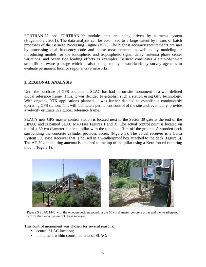
SLAC’s new GPS master control station is located next to the Sector 30 gate at the end of theLINAC and is named SLAC M40 (see Figures 1 and 3). The actual control point is located ontop of a 60 cm diameter concrete pillar with the top about 3 m off the ground. A wooden decksurrounding the concrete cylinder provides access (Figure 3). The actual receiver is a LeicaSystem 530 Base Receiver that is housed in a weatherproof box attached to the deck (Figure 3).The AT-504 choke ring antenna is attached to the top of the pillar using a Kern forced centeringmount (Figure 1).
This control monument was chosen for several reasons:��central SLAC location;��monument within controlled area of SLAC;
Figure 3 SLAC M40 with the wooden deck surrounding the 60 cm diameter concrete pillar and the weatherproofbox for the Leica System 530 base receiver.

6
��amount of visible sky is large enabling better GPS geometry;��RTK radio-modem coverage of SLAC nearly perfect;��permanent power access and potential network connectivity;��easy access for monitoring the equipment;��pillar and deck are in good condition.
The initial antenna mount was changed at the end of March 2002. At the same time the weatherradome was removed.
The tie to the global reference frame ITRF2000 is done in a regional analysis of GPS data with anetwork of well-established permanent GPS stations. The chosen network consists of sevenstations of the International GPS Service (IGS) plus the station SLAC M40. Figure 4 shows thegeographical distribution of all eight sites.
A detailed description of the processing steps being performed to derive accurate coordinates forSLAC M40 is beyond the scope of this paper. We limit the description to the following itemizedlist:
��Download RINEX, orbits, and ERP files,
Figure 4 Geographical distribution of the permanent IGS sites used in the regional analysis. The fourcharacter site codes represent the following stations: Colorado Springs (AMC2), Mammoth Lake(CASA), Penticton (DRAO), Pasadena (JPLM), Fort Davis (MDO1), Pietown (PIE1), Quincy (QUIN),Stanford (SLAC).

7
��Orbit computation,��Synchronization of receiver clocks,��Creation of baselines,��Data cleaning,��Ambiguity resolution,��Daily free network solution,��Combination of daily network solutions and datum fixing.
The GPS observation files are exchanged in the Receiver INdependent EXchange format(RINEX). ERP files contain the Earth orientation parameters (pole coordinates, UT1-UTC, UTC-GPStime).
The coordinates obtained for SLAC M40 refer to the antenna reference point (ARP) of the LeicaAT-504 GPS antenna. The ARP is located at the bottom of the preamplifier as indicated in theantenna diagram (Figure 5). By choosing the ARP instead of the physical marker of themonument, subsequent GPS RTK surveys need not be concerned about antenna heightinformation of the master control station.
Figures 6 and 7 show the coordinate time series plus velocity estimates of the North, East, andUp components of the arbitrarily chosen stations SLAC, CASA, and JPLM. Since the verticalcomponent is usually determined less accurately, the ‘Up panels’ were given a smaller scale.Although only some 5 months of data have been used, a clear trend is discernible in allhorizontal coordinate components. The horizontal performance of SLAC is comparable to JPLM,
Figure 5 Antenna diagram of the Leica AT-504 choke ring antenna. Coordinates refer to theARP (antenna reference point) located at the bottom of the preamplifier.

8
both being slightly better than CASA. The vertical component, on the other hand, is relativelynoisy as compared to JPLM. Still, a value of 3-4 is common for the relationship between verticaland horizontal accuracy.
Figure 6 Coordinate time series and velocity estimates for the station SLAC M40 over the timespan from May to October 2002.
Figure 7 Coordinate time series and velocity estimates for the stations CASA (Mammoth Lake) and JPLM(Pasadena) over the time span from May to October 2002.

9
The velocity estimates for the stations of the regional network as derived directly from the timeseries are compiled in Table 2. Table 3, in turn, contains the IGS published velocity values forthe same stations. The velocities found for SLAC agree with the nearby station of SUAA towithin a few mm/yr in all components. This is an indication that the velocity estimate for SLACis realistic, although it is only based on five months of data. Nonetheless, the limited amount ofdata manifests itself in larger discrepancies at other stations: CASA and DRAO, for instance,show differences as large as 30 mm/yr in the vertical and 15 mm/yr in the horizontalcomponents. This will hopefully be cured with more data becoming available.
4. RTK EXAMPLE
RTK is a method of surveying that allows for the use of GPS measurements from a well-determined station to be transferred to a rover thus providing real-time centimeter accuracywithout long point occupation times. The necessary hardware (cf. section 2) consists of two ormore GPS receivers and radio-modems. One receiver occupies a known reference station (such
Table 2 ITRF2000 station velocities (North, East and Up components) for the eight stations of theregional network as derived from the time series.
Station North East UpAMC2 -10.5 mm/yr -23.9 mm/yr -4.3 mm/yrCASA -19.0 mm/yr -8.2 mm/yr 31.2 mm/yrDRAO -24.6 mm/yr -3.7 mm/yr 0.7 mm/yrJPLM 15.9 mm/yr -31.0 mm/yr 0.5 mm/yrMDO1 -3.6 mm/yr -20.4 mm/yr 0.3 mm/yrPIE1 -11.8 mm/yr -18.2 mm/yr -17.4 mm/yrQUIN -7.2 mm/yr -0.7 mm/yr 11.9 mm/yrSLAC 15.5 mm/yr -27.2 mm/yr -12.9 mm/yr
Table 3 ITRF2000 station velocities (North, East and Up components) for the eight stations of theregional network as published by the IGS. Since for SLAC no published velocity value is available,the station SUAA was chosen which is located within a distance of less than 8 km from SLAC M40.
Station North East UpAMC2 -10.8 mm/yr -17.6 mm/yr -4.2 mm/yrCASA -9.8 mm/yr -21.7 mm/yr -1.9 mm/yrDRAO -11.7 mm/yr -13.4 mm/yr 1.2 mm/yrJPLM 11.2 mm/yr -37.1 mm/yr -1.6 mm/yrMDO1 -7.2 mm/yr -12.1 mm/yr -0.6 mm/yrPIE1 -9.8 mm/yr -13.8 mm/yr -0.5 mm/yrQUIN -5.6 mm/yr -21.3 mm/yr -6.9 mm/yrSUAA 10.6 mm/yr -24.5 mm/yr -14.1 mm/yr

10
as SLAC M40) and broadcasts a correction message to one or more of the roving receivers. Theroving receivers process the information from the reference station to solve for WGS-84 vectorsby real-time integer solutions. This gives an accurate position of the rover with respect to thereference station. Clearly a well determined reference station is needed to produce accurateroving results.
In terms of the time necessary for accurate data gathering, RTK allows a surveyor to occupy apoint of interest for only a few seconds instead of the numerous minutes otherwise needed. RTKis a GPS differential mode of operation using the very accurate carrier phase measurements forpoint position determination. The phase observations require a preliminary ambiguity resolutionbefore being useable. When phase lock is lost such as when measuring near trees or at a buildingcorner, RTK can be limited in its ability to measure those points. Thus at SLAC we have addedLeica’s DISTO system to our RTK package (Leica System 530). Combining RTK withtraditional survey methods allows for the mapping of objects that would otherwise not beaccessible by ordinary GPS methods.
As an example we show results of an RTK test survey of the loop road of the SLAC campus(Figure 8). The purpose of the survey was to map the centerline as well as the pavement edges ofthe loop road along with getting familiar with the equipment and procedures of the Leica system.The GPS results were transformed from the ITRF2000 reference datum to the NAD83 datumusing published transformation parameters (e.g., Soler, 2002). The resulting line work wasoverlaid onto an orthophoto of the SLAC campus that was provided in the same reference datum(NAD83).
Figure 8 Overlay of RTK GPS results on top of an orthophoto of the SLAC campus. The redline represents the loop road centerline, the two blue lines are the pavement edges.

11
From an eyeball inspection, no systematic discrepancies are discernible between the two datasets; i.e., there appears to be no datum problem. The overall agreement can be described as good.The time needed to obtain the three lines of about 4.6 km length each can be summarized asfollows: 1 hour to prepare setup, 12 hours of field work, and 4 hours of office work. Hence,altogether two working days of a single person are needed.
5. CONCLUSIONS
The Alignment Engineering Group of the Stanford Linear Accelerator Center (SLAC) started touse RTK (real-time kinematic) GPS equipment in order to perform structure mapping and GIS-related tasks on the SLAC campus. In a first step a continuously observing GPS station (SLACM40) was set up. This station serves as master control station for all differential GPS activitieson site and its coordinates have been determined in the well-defined global geodetic datumITRF2000 at a given reference epoch. Some trials have been performed to test the RTK method.The tests have proven RTK to be very fast and efficient.
From the first 5 months of data, an initial estimate of the station velocity of SLAC M40 has beendone giving a good indication of the true site velocity. Still, at least a complete year, preferablyseveral years, of uninterrupted data coverage is needed for allocating an accurate and reliablevelocity value to SLAC M40. A good estimate of this velocity, however, is a prerequisite formaking coordinate determinations comparable over time.
ACKNOWLEDGEMENTS
The authors would like to thank all members of the Alignment Engineering group for theirsupport and assistance. No results would have been possible without their efforts. A specialthanks goes to Brian Fuss for setting up the group’s GPS web page and his constant preparednessto give a helping hand if needed. The Stanford Linear Accelerator Center is operated by StanfordUniversity for the U.S. Department of Energy.
REFERENCES
Beutler, G., A. Geiger, M. Rothacher, S. Schaer, D. Schneider, A. Wiget (1995): Dreidimensionales TestnetzTurtmann 1985-1993 – Teil II (GPS-Netz). Geodätisch-geophysikalische Arbeiten in der Schweiz, Volume 51,Schweizerische Geodätische Kommission, Zürich, 1995.
Hugentobler, U., S. Schaer, P. Fridez (2001): Bernese GPS Software Version 4.2. Astronomical Institute of theUniversity of Berne, Berne, February 2001.
Langley, R.B. (1998): GPS Receivers and the Observables. In: P.J.G. Teunissen and A. Kleusberg (Eds.): GPS forGeodesy – 2nd Edition. Springer-Verlag, Berlin, 1998.

12
Leica (2001): http://www.leica-geosystems.com/gps/product/sr530.htm.
Leica (2002): http://www.leica-geosystems.com/gps/product/ski-pro.htm.
van Sickle, Jan (1996): GPS for Land Surveyors. Ann Arbor Press, Chelsea, Michigan, 1996.
Soler, T. (2002): Computing NAD83 Coordinates Using ITRF-Derived Vector Components. ACSM-ASPRS 2002Annual Conference Proceedings, Washington, DC, April 2002.