gpsmap 5000 series · information—shows information including tides, currents, celestial data,...
TRANSCRIPT

GPSMAP® 5000 Seriesowner’s manual

See the Important Safety and Product Information guide in the product box for product warnings and other important information.
© 2009 Garmin Ltd. or its subsidiariesGarmin International, Inc. 1200 East 151st Street, Olathe, Kansas 66062, USA Tel. (913) 397.8200 or (800) 800.1020 Fax (913) 397.8282
Garmin (Europe) Ltd. Liberty House Hounsdown Business Park, Southampton, Hampshire, SO40 9LR UK Tel. +44 (0) 870.8501241 (outside the UK) 0808 2380000 (within the UK) Fax +44 (0) 870.8501251
Garmin Corporation No. 68, Jangshu 2nd Road, Shijr, Taipei County, Taiwan Tel. 886/2.2642.9199 Fax 886/2.2642.9099
All rights reserved. Except as expressly provided herein, no part of this manual may be reproduced, copied, transmitted, disseminated, downloaded or stored in any storage medium, for any purpose without the express prior written consent of Garmin. Garmin hereby grants permission to download a single copy of this manual onto a hard drive or other electronic storage medium to be viewed and to print one copy of this manual or of any revision hereto, provided that such electronic or printed copy of this manual must contain the complete text of this copyright notice and provided further that any unauthorized commercial distribution of this manual or any revision hereto is strictly prohibited.Information in this document is subject to change without notice. Garmin reserves the right to change or improve its products and to make changes in the content without obligation to notify any person or organization of such changes or improvements. Visit the Garmin Web site (www.garmin.com) for current updates and supplemental information concerning the use and operation of this and other Garmin products.Garmin®, the Gamin logo, GPSMAP®, AutoLocate®, MapSource®, BlueChart®, and g2 Vision® are trademarks of Garmin Ltd. or its subsidiaries, registered in the USA and other countries. UltraScroll™, GFS™, and GHP™ are trademarks of Garmin Ltd. or its subsidiaries. These trademarks may not be used without the express permission of Garmin. NMEA 2000® and the NMEA 2000 logo are registered trademarks of the National Maritime Electronics Association. Windows® is a registered trademark of Microsoft Corporation in the United States and other countries. XM® and XM WX Satellite Weather® are registered trademarks of XM Satellite Radio Inc.
April 2009 Part Number 190-01079-00 Rev. A Printed in Taiwan
GPSMAP 5000 Series Owner’s Manual i
Introduction
IntroductionThis manual includes information for the following products:
GPSMAP® 5208GPSMAP 5212GPSMAP 5215
Tips and ShortcutsTouch Home from any screen to return to the Home screen.Touch Menu from any main screen to access additional settings.Press and release the Power key to adjust the display settings (Backlight and Color Mode).Press and hold the Power key to turn the chartplotter on or off.
Manual ConventionsIn this manual, when you are instructed to touch something, use your finger to touch that item on the screen. Small arrows (>) used in the text indicate that you should touch a series of items in order. For example, if you see, “Touch Charts > Navigation Chart,” you should touch the Charts button on the screen, and then touch Navigation Chart.
•••
••••

ii GPSMAP 5000 Series Owner’s Manual
Introduction
Table of ContentsIntroduction ........................................................... i
Tips and Shortcuts ...................................................... i
Manual Conventions ............................................ iGetting Started ..................................................... 1
Front and Rear Panels ..............................................1Turning the Chartplotter On .......................................2Turning the Chartplotter Off .......................................2Initializing Chartplotter Settings .................................2Acquiring GPS Satellite Signals ................................3Adjusting the Backlight ..............................................3Adjusting the Color Mode ..........................................3Inserting and Removing SD Cards ............................3Restoring the Original Factory Settings .....................4Viewing System Information ......................................4Using the Simulator Mode .........................................4Understanding the Home Screen ..............................5
Using Charts ........................................................ 6Using the Navigation Chart ........................................6Changing the Navigation Chart Settings .................11Using Perspective 3D ..............................................12Using Radar Overlay ...............................................14Using Tracks ............................................................14Using BlueChart g2 Vision .......................................15Using Mariner’s Eye 3D ...........................................16Using Fish Eye 3D ...................................................17Using Fishing Charts ...............................................18Enabling High Resolution Satellite Imagery ............18Viewing Aerial Photos ..............................................19Viewing Current Station Information ........................19Detailed Road and POI Data ...................................19Using Automatic Guidance ......................................20
Using Combinations .......................................... 21Selecting a Combination ..........................................21Interacting with the Combinations Screen ...............21Editing the Combination Screen ..............................22
Where To? .......................................................... 23Navigating to a Destination ......................................23Creating and Using Waypoints ................................25Creating and Using Routes .....................................27Navigating with a Garmin Autopilot ..........................29
Viewing Information .......................................... 30Viewing Tide Station Information .............................30Viewing Current Information ....................................30Viewing Celestial Information ..................................31Viewing User Data ...................................................32Viewing the DSC List ...............................................34Viewing Gauges ......................................................34Viewing Fuel Gauges ..............................................34Viewing Video ..........................................................35
Configuring the Device ..................................... 36Configuring System Settings ...................................36Changing the System Language .............................36Configuring Navigation Preferences ........................36Configuring Units of Measure ..................................37Configuring Communications Settings ....................38Setting Alarms .........................................................39Setting the Total Fuel Onboard Alarm ......................40Configuring My Boat ................................................40
Configuring Other Vessels .......................................41Configuring XM Audio ..............................................42
Using the Marine Network ................................ 43Viewing Connected Garmin Marine Network Devices ....................................................................44
Using Radar ....................................................... 45Using Cruising Mode ...............................................46Using Sentry Mode ..................................................46Radar Targeting .......................................................47Understanding the Radar Overlay Screen...............48Obtaining Optimal Radar Display Performance .......49Adjusting the VRM and EBL ....................................49Configuring Other Vessels on the Radar Screen.....50Advanced Radar Configuration ...............................50
Using Sonar ....................................................... 51Understanding the Full Screen ................................51Understanding the Split Zoom Screen .....................51Understanding the Split Frequency Screen .............52Understanding the Temp Log ..................................52Setting Up Sonar .....................................................53
Digital Selective Calling (DSC) ......................... 55Using the Chartplotter with a VHF Radio .................55Adding a DSC Contact ............................................55Viewing the DSC List ...............................................56Receiving Distress Calls ..........................................56Man-Overboard Distress Calls Initiated from a VHF Radio ...............................................................56Man-Overboard Distress Calls Initiated from the Chartplotter ..............................................................56Position Tracking .....................................................57Placing an Individual Routine Call ...........................58Calling an AIS Target ...............................................58
Using XM WX Weather and Audio .................... 59Using XM WX Weather ............................................59Viewing NEXRAD Precipitation Information ............59Viewing Forecast Information ..................................61Viewing Sea Conditions ...........................................62Viewing Fishing Information ....................................63Viewing Visibility Information ...................................64Viewing Buoy Reports .............................................65Using XM Audio .......................................................66
Appendix ............................................................ 67Specifications ..........................................................67Calibrating the Touchscreen ....................................68Capturing Screenshots ............................................68NMEA 0183 and NMEA 2000 ..................................69Messages and Alarms .............................................70Product Registration ................................................74Contact Garmin .......................................................74Declaration of Conformity (DoC) .............................74Weather Data Warranty ...........................................74Software License Agreement ...................................75XM Satellite Radio Service Agreement ....................75
Index ................................................................... 76

GPSMAP 5000 Series Owner’s Manual �
Getting Started G
ettinG
Sta
rted
Getting Started
Front and Rear Panels
SD card slot
Power key
Automatic backlight sensor
GPSMAP 5208 - Front
Network
NMEA 2000®
Video
Power
NMEA 0�83
GPSMAP 5212 - Back

2 GPSMAP 5000 Series Owner’s Manual
Getting StartedG
etti
nG
Sta
rte
d Turning the Chartplotter On Note: The first time you power on your chartplotter, you must go through a setup sequence. See “Initializing Chartplotter Settings”.
1. Press and release the Power key. After a few moments, the Warning screen appears.
Warning Screen Home Screen
2. Touch I Agree to open the Home screen.
Turning the Chartplotter OffTo turn the chartplotter off, press and hold the Power key.
Initializing Chartplotter SettingsThe first time you turn your chartplotter on, you must configure a series of initial settings. These settings must also be configured when restoring factory settings (page 4). All of these settings can be configured later from the Configure screen (page 36).
The initial settings are as follows:
Language—touch the language that you want shown on your screen.Welcome—touch oK.Position Format—specify the coordinate system to use for location readings.time Format—select 12-hour, 24-hour, or UtC (Universal Time Code) to specify the format in which time is displayed.time Zone—select your time zone.Units—select Statute, Metric, or Nautical to specify units for on-screen measurements.Minimum Safe Depth—specify the minimum safe depth for your boat. Refer to your boat specifications for more information.Minimum overhead Clearance—specify the minimum overhead clearance for your boat. Refer to your boat specifications for more information.
••••
•••
•

GPSMAP 5000 Series Owner’s Manual 3
Getting Started G
ettinG
Sta
rted
Acquiring GPS Satellite SignalsWhen you turn the chartplotter on, the GPS receiver must collect satellite data and establish its current location. When the chartplotter acquires satellite signals, the signal strength bars at the top of the Home screen are green . When the chartplotter loses satellite signals, the green bars disappear and a flashing question mark appears on the boat icon on the chart screen.
For more information about GPS, visit the Garmin Web site at www.garmin.com/aboutGPS.
Adjusting the Backlight1. While the chartplotter is on, press and quickly release the Power key.2. Touch Backlight.3. Select an option to adjust the backlight:
To allow the chartplotter to automatically adjust the backlight based on ambient light, touch Auto.To manually adjust the backlight, either touch and hold Up or Down, or touch and drag the brightness bar.
Brightness bar
Adjusting the Color Mode1. Press and quickly release the Power key.2. Touch Color Mode.3. Touch Day Colors, Night Colors, or Auto.
Inserting and Removing SD CardsYour chartplotter supports SD (Secure Digital) cards. Insert optional BlueChart® g2 Vision® SD cards to view high-resolution satellite imagery and aerial reference photos of ports, harbors, marinas, and other points of interest. Insert blank SD cards to transfer data such as waypoints, routes, and tracks to another compatible Garmin chartplotter or a computer (page 32). The SD card slot is located on the lower-right corner of the chartplotter.
To insert the SD card, open the access door and press the SD card until it clicks.To eject the SD card, press the card in again and release it.
•
•
•
•Card labelCard label

� GPSMAP 5000 Series Owner’s Manual
Getting StartedG
etti
nG
Sta
rte
d Restoring the Original Factory Settings CaUtioN: This procedure deletes any information you have entered.
1. From the Home screen, touch Configure > System > System Information > Factory Settings > Reset.
2. Select an option:Touch Yes to restore all factory settings.Touch No to exit without restoring factory settings.
Viewing System InformationYou can view the software version, basemap version, unit ID number, and your XM WX Weather® radio ID (if available). You may need this information to update the system software or purchase additional map data information.
From the Home screen, touch Configure > System > System information.
Using the Simulator ModeSimulator mode turns the GPS receiver off for use indoors or for practice. The chartplotter does not track satellites in simulator mode.
CaUtioN: Do not try to navigate using simulator mode because the GPS receiver is turned off. Any satellite signal strength bars shown are only simulations and do not represent the strength of actual satellite signals.
1. From the Home screen, touch Configure > System > Simulator > On.2. Touch Setup to set speed, track control (simulated heading), position, simulator time, and
simulator date.
••

GPSMAP 5000 Series Owner’s Manual 5
Getting Started G
ettinG
Sta
rted
Understanding the Home ScreenUse the Home screen to access all other screens.
Note: Options on this screen vary based on the chartplotter type and optional connected network devices.
Charts—selects Navigation Chart, Perspective 3D, Mariner’s Eye 3D, Fish Eye 3D, Fishing Chart, and Radar Overlay (page 6).
Note: Mariner’s Eye 3D, Fish Eye 3D, and Fishing Charts are available only if you use a BlueChart g2 Vision SD card.
Sonar—sets up and provides sonar information (only available if the chartplotter is connected to a Garmin sonar module) (page 51).Combinations—sets up the screen to view a chart, sonar, radar, and video in a 2, 3, or 4-field split screen (page 21).information—shows information including tides, currents, celestial data, user data, information about other boats, gauges, and video (page 30).Mark—marks, edits, or deletes your current location as a waypoint or Man Overboard (page 25).Where to?—provides navigation features (page 23).Radar—sets up and displays radar (only available if the chartplotter is connected to a radar module) (page 45).Weather—sets up and displays various weather parameters, including precipitation, forecast, fishing, sea conditions, and visibility (only available if the chartplotter is connected to a weather module and you have an XM® subscription) (page 59).Configure—allows you to view and edit your chartplotter and system settings (page 36).Man overboard—marks your current location as a waypoint, and sets a course back to the marked location. (page 25).
•
•
•
•
•••
•
••
� GPSMAP 5000 Series Owner’s Manual
Using ChartsU
Sin
G
Ch
ar
tS
Using ChartsThe GPSMAP 5000 series chartplotters have a basic worldwide imagery map and built-in detailed BlueChart g2 offshore cartography for US waters. The following options are available when you touch Charts on the Home screen:
Navigation Chart—displays navigation data available on your preloaded maps, including buoys, lights, cables, depth soundings, marinas, and tide stations in an overhead view.Perspective 3D—displays a view from above and behind your boat for a visual navigation aid.
Note: Mariner’s Eye 3D, Fishing Charts and Fish Eye 3D views are available when using optional Blue Chart g2 Vision preprogrammed SD cards. See page 16.
Mariner’s eye 3D—displays a detailed, three-dimensional view from above and behind the boat for a visual navigation aid.Fishing Chart—removes navigational data from the chart and enhances bottom contours for depth recognition.Fish eye 3D—provides an underwater view that visually represents the sea floor according to the chart’s information.
The chartplotter selectively displays navigation data after you select the type of navigation you want.
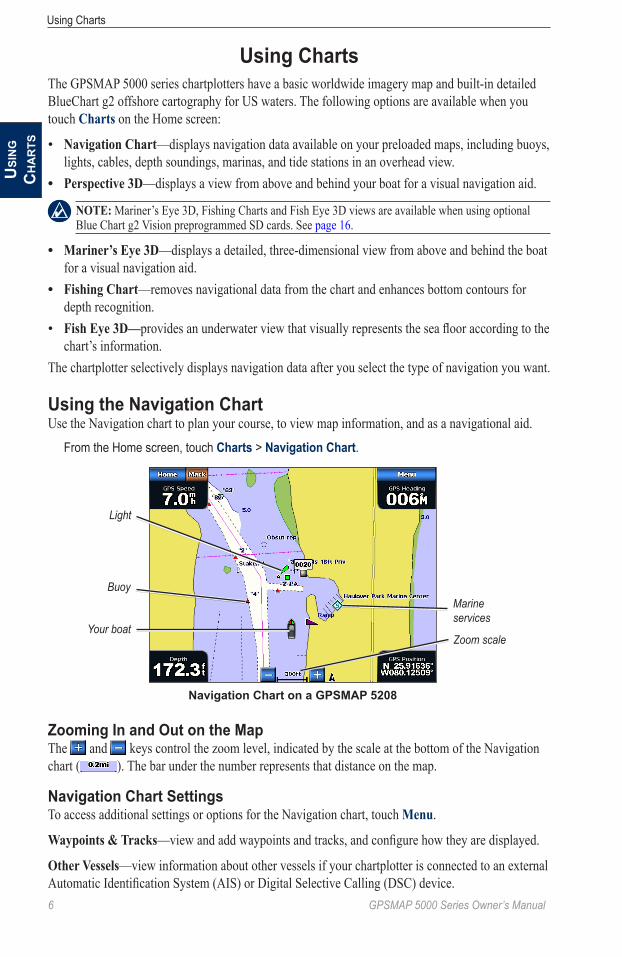
Using the Navigation ChartUse the Navigation chart to plan your course, to view map information, and as a navigational aid. From the Home screen, touch Charts > Navigation Chart.
Navigation Chart on a GPSMAP 5208
Buoy
Your boat
Marine services
Zoom scale
Light
Zooming In and Out on the MapThe and keys control the zoom level, indicated by the scale at the bottom of the Navigation chart ( ). The bar under the number represents that distance on the map.
Navigation Chart SettingsTo access additional settings or options for the Navigation chart, touch Menu.
Waypoints & tracks—view and add waypoints and tracks, and configure how they are displayed.
other Vessels—view information about other vessels if your chartplotter is connected to an external Automatic Identification System (AIS) or Digital Selective Calling (DSC) device.
•
•
•
•
•
GPSMAP 5000 Series Owner’s Manual �
Using ChartsU
SinG
Ch
ar
tS
Stop Navigation—stop navigating to your destination (only available while navigating).
Chart Setup—customize the Navigation chart settings (page 11).
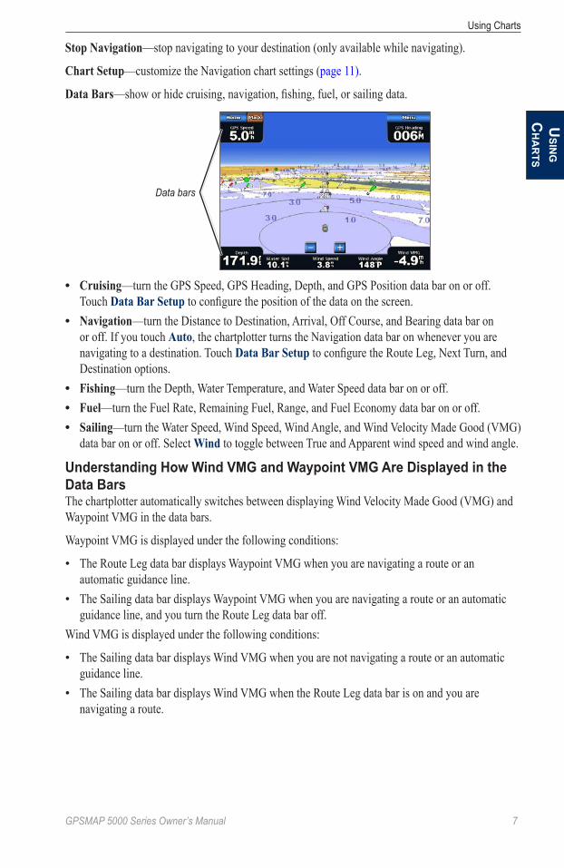
Data Bars—show or hide cruising, navigation, fishing, fuel, or sailing data.
Data bars
Cruising—turn the GPS Speed, GPS Heading, Depth, and GPS Position data bar on or off. Touch Data Bar Setup to configure the position of the data on the screen.Navigation—turn the Distance to Destination, Arrival, Off Course, and Bearing data bar on or off. If you touch auto, the chartplotter turns the Navigation data bar on whenever you are navigating to a destination. Touch Data Bar Setup to configure the Route Leg, Next Turn, and Destination options.Fishing—turn the Depth, Water Temperature, and Water Speed data bar on or off.Fuel—turn the Fuel Rate, Remaining Fuel, Range, and Fuel Economy data bar on or off.Sailing—turn the Water Speed, Wind Speed, Wind Angle, and Wind Velocity Made Good (VMG) data bar on or off. Select Wind to toggle between True and Apparent wind speed and wind angle.
Understanding How Wind VMG and Waypoint VMG Are Displayed in the Data BarsThe chartplotter automatically switches between displaying Wind Velocity Made Good (VMG) and Waypoint VMG in the data bars.
Waypoint VMG is displayed under the following conditions:
The Route Leg data bar displays Waypoint VMG when you are navigating a route or an automatic guidance line.The Sailing data bar displays Waypoint VMG when you are navigating a route or an automatic guidance line, and you turn the Route Leg data bar off.
Wind VMG is displayed under the following conditions:
The Sailing data bar displays Wind VMG when you are not navigating a route or an automatic guidance line.The Sailing data bar displays Wind VMG when the Route Leg data bar is on and you are navigating a route.
•
•
•••
•
•
•
•
8 GPSMAP 5000 Series Owner’s Manual
Using ChartsU
Sin
G
Ch
ar
tS
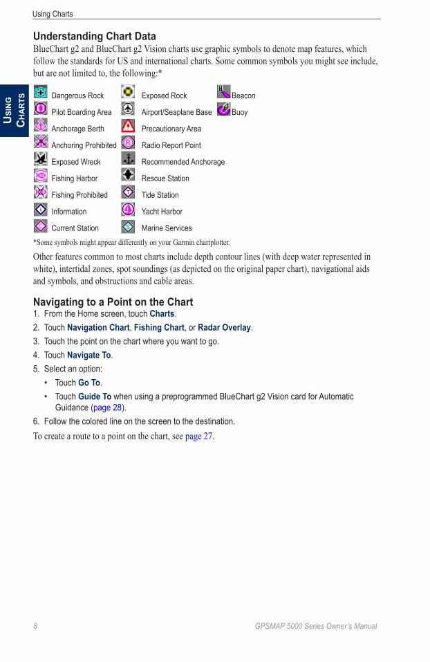
Understanding Chart DataBlueChart g2 and BlueChart g2 Vision charts use graphic symbols to denote map features, which follow the standards for US and international charts. Some common symbols you might see include, but are not limited to, the following:*
Dangerous Rock Exposed Rock Beacon
Pilot Boarding Area Airport/Seaplane Base Buoy
Anchorage Berth Precautionary Area
Anchoring Prohibited Radio Report Point
Exposed Wreck Recommended Anchorage
Fishing Harbor Rescue Station
Fishing Prohibited Tide Station
Information Yacht Harbor
Current Station Marine Services
*Some symbols might appear differently on your Garmin chartplotter.
Other features common to most charts include depth contour lines (with deep water represented in white), intertidal zones, spot soundings (as depicted on the original paper chart), navigational aids and symbols, and obstructions and cable areas.
Navigating to a Point on the Chart1. From the Home screen, touch Charts.2. Touch Navigation Chart, Fishing Chart, or Radar Overlay.3. Touch the point on the chart where you want to go.4. Touch Navigate To.5. Select an option:
Touch Go To.Touch Guide To when using a preprogrammed BlueChart g2 Vision card for Automatic Guidance (page 28).
6. Follow the colored line on the screen to the destination.To create a route to a point on the chart, see page 27.
••
GPSMAP 5000 Series Owner’s Manual �
Using ChartsU
SinG
Ch
ar
tS
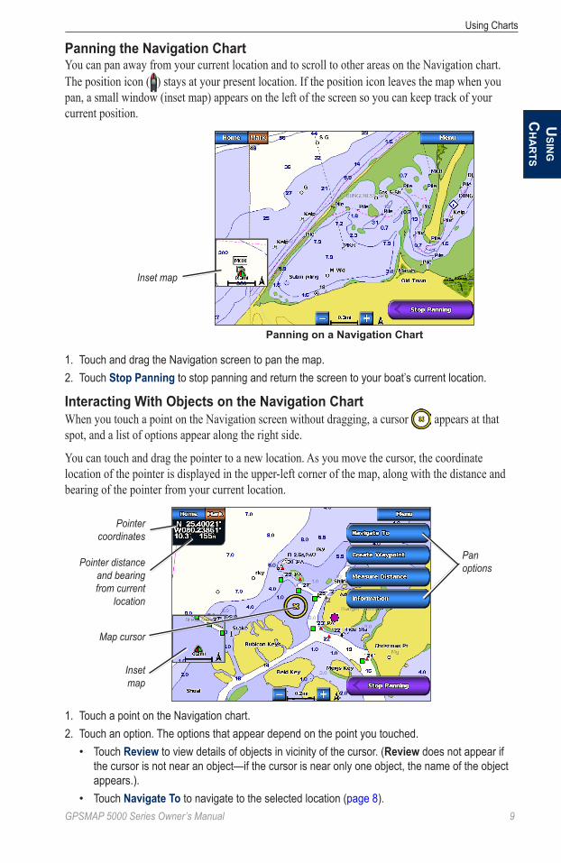
Panning the Navigation ChartYou can pan away from your current location and to scroll to other areas on the Navigation chart. The position icon ( ) stays at your present location. If the position icon leaves the map when you pan, a small window (inset map) appears on the left of the screen so you can keep track of your current position.
Panning on a Navigation Chart
Inset map
1. Touch and drag the Navigation screen to pan the map.2. Touch Stop Panning to stop panning and return the screen to your boat’s current location.
Interacting With Objects on the Navigation ChartWhen you touch a point on the Navigation screen without dragging, a cursor appears at that spot, and a list of options appear along the right side.
You can touch and drag the pointer to a new location. As you move the cursor, the coordinate location of the pointer is displayed in the upper-left corner of the map, along with the distance and bearing of the pointer from your current location.
Map cursor
Inset map
Pointer distance and bearing from current
location
Pointer coordinates
Pan options
1. Touch a point on the Navigation chart.2. Touch an option. The options that appear depend on the point you touched.
Touch Review to view details of objects in vicinity of the cursor. (Review does not appear if the cursor is not near an object—if the cursor is near only one object, the name of the object appears.).Touch Navigate To to navigate to the selected location (page 8).
•
•

�0 GPSMAP 5000 Series Owner’s Manual
Using ChartsU
Sin
G
Ch
ar
tS
Touch Create Waypoint to mark a waypoint at the cursor location (page 25).Touch Measure Distance to view the distance and bearing of the object from your current location. The information is displayed in the upper-left corner of the screen. Touch Set Reference to measure from a location other than your current location.Touch Information to view tide (page 30), current (page 30), celestial (page 31), or local services information near the cursor.
Accessing Additional Object Information1. Touch an item on the screen to view information about on-screen map items, waypoints, and
charts.2. Touch the button with the name of the item to view the information.
Object Selected on a GPSMAP 5208
Selected item
Additional object information
Viewing Tide-Station InformationTide-station information appears on the chart with a detailed icon showing the relevant tide level. You can view a detailed graph for a tide station to help predict the tide level at different times or on different days. For more information about tides, see page 30.
Tide level Detailed tide station information
Tide Station Selected on a GPSMAP 5208
1. Touch a tide station icon ( ).2. To view a detailed tide graph:
Touch the button with the station name. Touch Review if more than one item is in the vicinity, and then touch the button with the station name.
••
•
••

GPSMAP 5000 Series Owner’s Manual ��
Using ChartsU
SinG
Ch
ar
tS
Changing the Navigation Chart SettingsFrom the Home screen, touch Charts > Navigation Chart > Menu > Chart Setup.
Photos—sets the high-resolution satellite images to off, Land only, or Photo Map. High-resolution satellite imagery is only available while using a BlueChart g2 Vision SD card (page 18).
tides/Currents—turns the display of tides and currents on or off.
Service Points—turns the display of marine service points on or off.
Roses—displays a compass rose around your boat, indicating compass direction. True wind direction or apparent wind direction can be displayed if the chartplotter is connected to a compatible marine wind sensor.
Compass rose
Wind direction indicator
Wind Compass Rose
Changing the Chart AppearanceFrom the Home screen, touch Charts > Navigation Chart > Menu > Chart Setup > Chart appearance.
Heading line
Track
Chart border
orientation—changes the perspective of the map display.
North Up—sets the top of the map display to a north heading.Head Up—sets the map display to the current track heading.Course Up—sets the map so the direction of navigation is always up. The heading line appears vertically on the screen if shown.
Detail—adjusts the amount of detail shown on the map at different zoom levels.
•••
�2 GPSMAP 5000 Series Owner’s Manual
Using ChartsU
Sin
G
Ch
ar
tS
Heading Line—draws an extension from the bow of the boat in the direction of travel.
off—turns the heading line off.Distance—sets the distance to the end of the heading line.time—sets the amount of time until you reach the end of the heading line.
World Map—displays either a basic world map or displays satellite imagery (when Full World Map is selected).
inset Map—turns the inset map on or off when panning away (page 9). Touch auto to turn the inset map on only when the boat symbol is no longer visible.
Spot Depths—turns spot soundings on or off and sets a dangerous depth.
Safety Shading (with supported BlueChart g2 Vision cards)—Areas with depths shallower than the specified value are shaded in blue, while areas with depths greater than the specified value are shaded in white. The contour is always drawn at or deeper than the selected depth.
Symbols—changes symbol preferences.
Navaid Size—adjusts the size of the navaid symbols shown on the map.Navaid type—selects the navaid symbol set (NOAA or IALA).Land Pois—turns the display of land POIs (points of interest) on or off.Light Sectors—turns the sector in which a navigational light is visible on or off. Selecting on filters out light sectors depending on the zoom level.Chart Borders—turns chart borders on when using a BlueChart g2 Vision SD card and you want to see what area the maps cover.
Photo Points—turns camera icons on or off when using a BlueChart g2 Vision SD card.
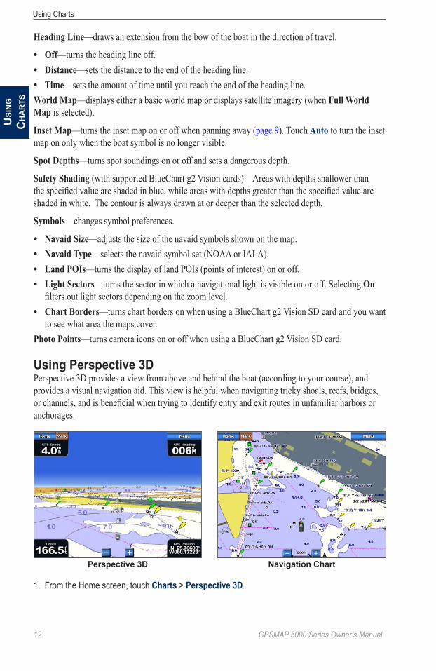
Using Perspective 3DPerspective 3D provides a view from above and behind the boat (according to your course), and provides a visual navigation aid. This view is helpful when navigating tricky shoals, reefs, bridges, or channels, and is beneficial when trying to identify entry and exit routes in unfamiliar harbors or anchorages.
Perspective 3D Navigation Chart
1. From the Home screen, touch Charts > Perspective 3D.
•••
••••
•

GPSMAP 5000 Series Owner’s Manual �3
Using ChartsU
SinG
Ch
ar
tS
2. Use the and buttons to adjust the view:Touch the button to move the view closer to your boat and lower to the water. Touch the button to move the view away from the boat.
The view is momentarily indicated by the scale ( ) at the bottom of the screen.
To view details about navaids such as beacons, lights, and obstructions:1. Use the touchscreen to point to the navaid. When the cursor is over the navaid, an option is
displayed, such as Beacon or Light.2. Touch the option for the navaid to view details.
Perspective 3D SettingsTo access additional settings or options from the Perspective 3D screen, touch Menu.
Waypoints & tracks—view and add waypoints and tracks, and configure how they are displayed.
tracks—turn tracks on or off (page 14).Waypoints—view, sort, or filter existing waypoints, or create new ones (page 25).New Waypoint—edit, delete, or create a new waypoint (page 25).active tracks—manage tracks (page 14).Saved tracks—view a list of tracks that have been saved.
other Vessels—view information about other vessels. To view information about other vessels, your chartplotter must be connected to an external Automatic Identification System (AIS) or Digital Selective Calling (DSC) device.
Surface Radar—display radar returns from the surface of the water when the chartplotter is connected to a marine radar (page 48).
Perspective 3D With Surface Radar Information
Data Bars—show or hide cruising, navigation, fishing, fuel, or sailing numbers (page 7).
Chart appearance—customize the Perspective 3D chart.
Range Rings—toggles the range rings on or off. The range rings help you to visualize distances on the map.Safe Depth—adjusts the safe depth for your boat. If the chartplotter is connected to an optional sonar module and the shallow water alarm is activated (page 72), an alarm will sound when your boat enters water shallower than this setting.Lane Width—adjusts the width of the course line drawn when navigating. This setting also affects routes (Route To), but does not affect automatic guidance (Guide To).
••
•••••
•
•
•
�� GPSMAP 5000 Series Owner’s Manual
Using ChartsU
Sin
G
Ch
ar
tS
Using Radar OverlayWhen you connect your chartplotter to an optional Garmin marine radar, you can use Radar Overlay to overlay radar information on the Navigation chart (page 48).
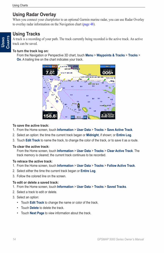
Using TracksA track is a recording of your path. The track currently being recorded is the active track. An active track can be saved.
To turn the track log on: From the Navigation or Perspective 3D chart, touch Menu > Waypoints & Tracks > Tracks >
On. A trailing line on the chart indicates your track.
To save the active track:1. From the Home screen, touch Information > User Data > Tracks > Save Active Track.2. Select an option: the time the current track began or Midnight, if shown; or Entire Log.3. Touch Edit Track to name the track, to change the color of the track, or to save it as a route.
To clear the active track:From the Home screen, touch Information > User Data > Tracks > Clear Active Track. The track memory is cleared; the current track continues to be recorded.
To retrace the active track:1. From the Home screen, touch Information > User Data > Tracks > Follow Active Track.2. Select either the time the current track began or Entire Log.3. Follow the colored line on the screen.
To edit or delete a saved track:1. From the Home screen, touch Information > User Data > Tracks > Saved Tracks.2. Select a track to edit or delete.3. Select an option:
Touch Edit Track to change the name or color of the track.Touch Delete to delete the track.Touch Next Page to view information about the track.
•••

GPSMAP 5000 Series Owner’s Manual �5
Using ChartsU
SinG
Ch
ar
tS
To set active Track Options:From the Home screen, touch Information > User Data > Tracks > Active Track Options.Record Mode—touch off, Fill, or Wrap.
off—does not record a track log.Fill—records a track log until the track memory is full.Wrap—continuously records the track log, replacing the oldest track data with new data.
interval—defines the frequency at which the track plot is recorded. Recording more-frequent plots is more accurate but fills the track log faster.
interval—sets whether the interval is determined by distance, time, or resolution. (Touch Change to set the quantity.)
Distance—records the track based on a distance between points.time—records the track based on a time interval.Resolution—records the track plot based on a variance from your course. This setting is recommended for the most-efficient use of memory. The distance value (Change) is the maximum error allowed from the true course before recording a track point.
Change—sets the value of the interval.track Color—sets the color of the track plot.
Using BlueChart g2 VisionOptional BlueChart g2 Vision preprogrammed SD cards allow you to get the most out of your chartplotter. In addition to detailed marine charting, BlueChart g2 Vision has the following features:
Mariner’s eye 3D—provides a view from above and behind the boat for a three-dimensional navigation aid. The BlueChart g2 Vision Mariner’s Eye 3D is more detailed than the preloaded data.Fish eye 3D—provides an underwater, three-dimensional view that visually represents the sea floor according to the information on the chart.Fishing Charts—displays the chart with enhanced bottom contours and without navigational data. This chart works well for offshore deep-sea fishing.High Resolution Satellite imagery—provides high resolution satellite images for a realistic view of the land and water on the Navigation chart.aerial Photos—displays marinas and other navigationally significant aerial photos to help you visualize your surroundings.Detailed Roads and Poi data—displays roads, restaurants, and other points of interest (POIs) along the shore.auto Guidance—uses specified boat safe depth and chart data to determine the best course to your destination.
•••
•
◦◦◦
•
•
•
•
•
•
•
•
�� GPSMAP 5000 Series Owner’s Manual
Using ChartsU
Sin
G
Ch
ar
tS
Using a BlueChart g2 Vision SD CardYou can insert or remove a BlueChart g2 Vision SD card while your chartplotter is on or off. See page 3 for insertion and removal instructions.
BlueChart g2 Vision SD cards are not waterproof. When you are not using the card, keep it in the original packaging for safekeeping and store it away from exposure to sun and rain.
BlueChart g2 Vision SD cards are susceptible to damage from static electricity. In low humidity environments, you should ground yourself on a large metal object before handling the card.
Note: You cannot transfer BlueChart g2 Vision data from the SD card to your computer for backup or viewing purposes. You can use the SD card only on BlueChart g2 Vision-compatible Garmin GPS units.
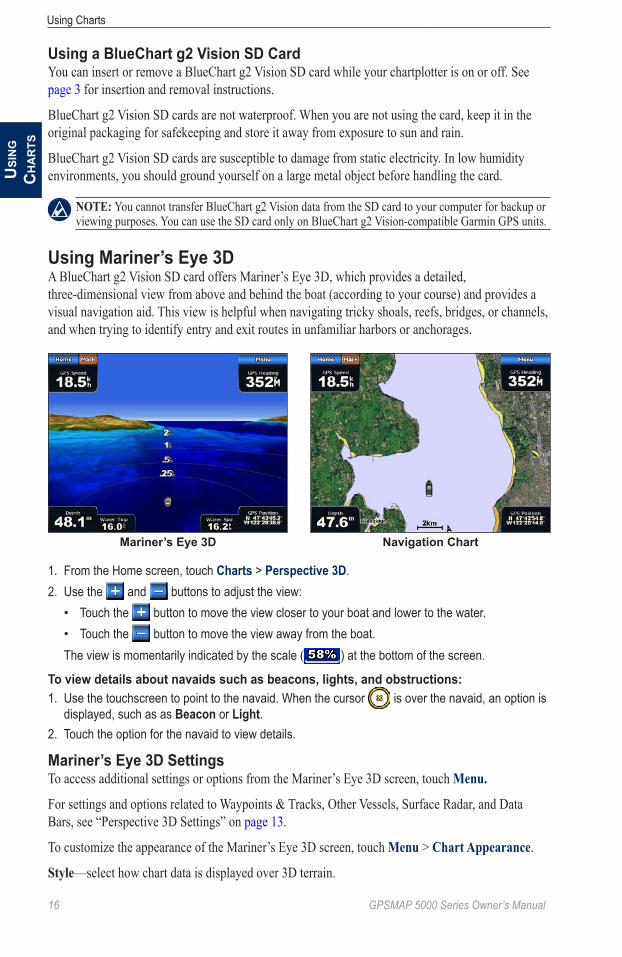
Using Mariner’s Eye 3DA BlueChart g2 Vision SD card offers Mariner’s Eye 3D, which provides a detailed, three-dimensional view from above and behind the boat (according to your course) and provides a visual navigation aid. This view is helpful when navigating tricky shoals, reefs, bridges, or channels, and when trying to identify entry and exit routes in unfamiliar harbors or anchorages.
Mariner’s Eye 3D Navigation Chart
1. From the Home screen, touch Charts > Perspective 3D.2. Use the and buttons to adjust the view:
Touch the button to move the view closer to your boat and lower to the water. Touch the button to move the view away from the boat.
The view is momentarily indicated by the scale ( ) at the bottom of the screen.
To view details about navaids such as beacons, lights, and obstructions:1. Use the touchscreen to point to the navaid. When the cursor is over the navaid, an option is
displayed, such as as Beacon or Light.2. Touch the option for the navaid to view details.
Mariner’s Eye 3D SettingsTo access additional settings or options from the Mariner’s Eye 3D screen, touch Menu.
For settings and options related to Waypoints & Tracks, Other Vessels, Surface Radar, and Data Bars, see “Perspective 3D Settings” on page 13.
To customize the appearance of the Mariner’s Eye 3D screen, touch Menu > Chart appearance.
Style—select how chart data is displayed over 3D terrain.
••
GPSMAP 5000 Series Owner’s Manual ��
Using ChartsU
SinG
Ch
ar
tS
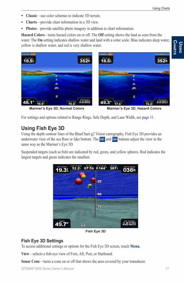
Classic—use color schemes to indicate 3D terrain.Charts—provide chart information in a 3D view.Photos—provide satellite photo imagery in addition to chart information.
Hazard Colors—turns hazard colors on or off. The off setting shows the land as seen from the water. The on setting indicates shallow water and land with a color scale. Blue indicates deep water, yellow is shallow water, and red is very shallow water.
Mariner’s Eye 3D, Normal Colors Mariner’s Eye 3D, Hazard Colors
For settings and options related to Range Rings, Safe Depth, and Lane Width, see page 11.
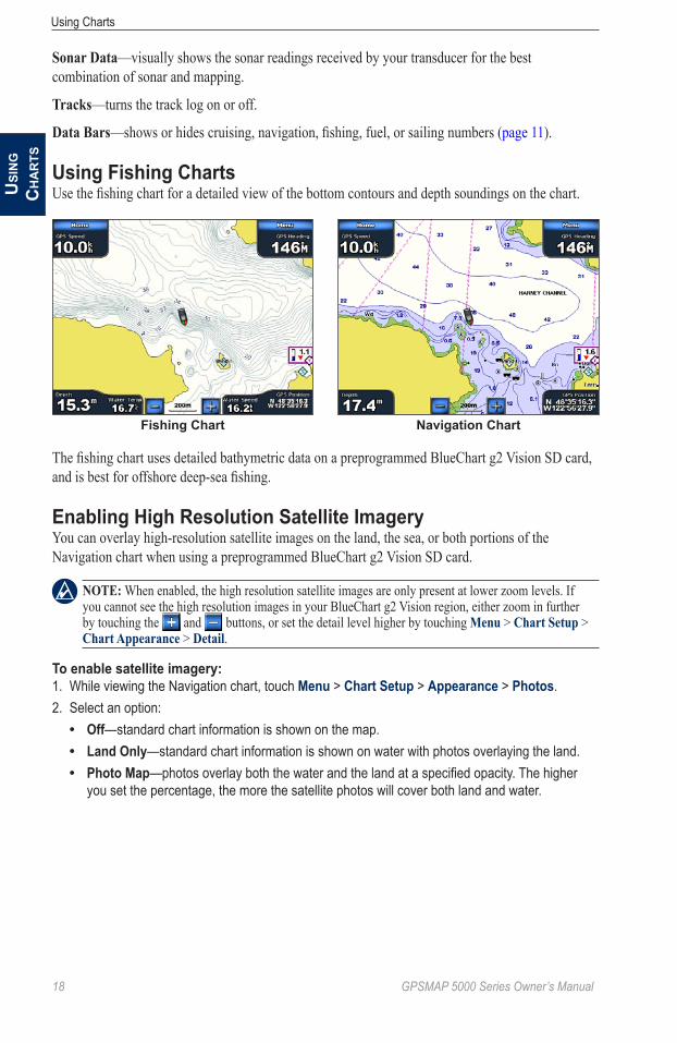
Using Fish Eye 3DUsing the depth contour lines of the BlueChart g2 Vision cartography, Fish Eye 3D provides an underwater view of the sea floor or lake bottom. The and buttons adjust the view in the same way as the Mariner’s Eye 3D.
Suspended targets (such as fish) are indicated by red, green, and yellow spheres. Red indicates the largest targets and green indicates the smallest.
Fish Eye 3D
Fish Eye 3D SettingsTo access additional settings or options for the Fish Eye 3D screen, touch Menu.
View—selects a fish-eye view of Fore, Aft, Port, or Starboard.
Sonar Cone—turns a cone on or off that shows the area covered by your transducer.
•••
�8 GPSMAP 5000 Series Owner’s Manual
Using ChartsU
Sin
G
Ch
ar
tS
Sonar Data—visually shows the sonar readings received by your transducer for the best combination of sonar and mapping.
tracks—turns the track log on or off.
Data Bars—shows or hides cruising, navigation, fishing, fuel, or sailing numbers (page 11).
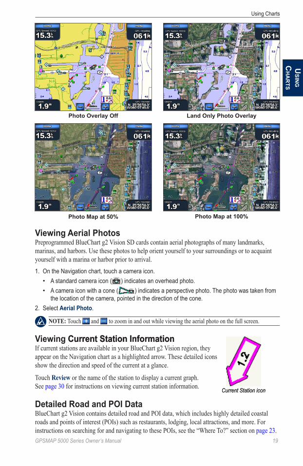
Using Fishing ChartsUse the fishing chart for a detailed view of the bottom contours and depth soundings on the chart.
Fishing Chart Navigation Chart
The fishing chart uses detailed bathymetric data on a preprogrammed BlueChart g2 Vision SD card, and is best for offshore deep-sea fishing.
Enabling High Resolution Satellite ImageryYou can overlay high-resolution satellite images on the land, the sea, or both portions of the Navigation chart when using a preprogrammed BlueChart g2 Vision SD card.
Note: When enabled, the high resolution satellite images are only present at lower zoom levels. If you cannot see the high resolution images in your BlueChart g2 Vision region, either zoom in further by touching the and buttons, or set the detail level higher by touching Menu > Chart Setup > Chart appearance > Detail.
To enable satellite imagery:1. While viewing the Navigation chart, touch Menu > Chart Setup > Appearance > Photos.2. Select an option:
Off—standard chart information is shown on the map.Land Only—standard chart information is shown on water with photos overlaying the land.Photo Map—photos overlay both the water and the land at a specified opacity. The higher you set the percentage, the more the satellite photos will cover both land and water.
•••
GPSMAP 5000 Series Owner’s Manual ��
Using ChartsU
SinG
Ch
ar
tS
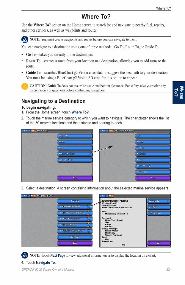
Photo Map at 50% Photo Map at 100%
Photo Overlay Off Land Only Photo Overlay
Viewing Aerial PhotosPreprogrammed BlueChart g2 Vision SD cards contain aerial photographs of many landmarks, marinas, and harbors. Use these photos to help orient yourself to your surroundings or to acquaint yourself with a marina or harbor prior to arrival.1. On the Navigation chart, touch a camera icon.
A standard camera icon ( ) indicates an overhead photo.A camera icon with a cone ( ) indicates a perspective photo. The photo was taken from the location of the camera, pointed in the direction of the cone.
2. Select Aerial Photo.
Note: Touch and to zoom in and out while viewing the aerial photo on the full screen.
Viewing Current Station InformationCurrent Station InformationIf current stations are available in your BlueChart g2 Vision region, they appear on the Navigation chart as a highlighted arrow. These detailed icons show the direction and speed of the current at a glance.
Touch Review or the name of the station to display a current graph. See page 30 for instructions on viewing current station information.
Detailed Road and POI DataBlueChart g2 Vision contains detailed road and POI data, which includes highly detailed coastal roads and points of interest (POIs) such as restaurants, lodging, local attractions, and more. For instructions on searching for and navigating to these POIs, see the “Where To?” section on page 23.
••
Current Station iconCurrent Station icon

20 GPSMAP 5000 Series Owner’s Manual
Using ChartsU
Sin
G
Ch
ar
tS
Using Automatic GuidanceAutomatic Guidance automatically creates and suggests passage based on available BlueChart g2 Vision chart information. See page 40 for instructions on setting up Automatic Guidance for your boat. See page 28 to use Automatic Guidance.

GPSMAP 5000 Series Owner’s Manual 2�
Using CombinationsU
SinG
Co
mb
inatio
nS
Using CombinationsThe Combinations screen displays a combination of different screens at the same time. The number of options available on the Combinations screen depends on the optional network devices you have connected to your GPSMAP 5000 series chartplotter and whether you are using an optional BlueChart g2 Vision SD card. You can combine two, three, or four screens. After you select a combination, you can customize it.
Selecting a Combination1. From the Home screen, touch Combinations. A list of possible screen combinations is displayed.2. Touch a combination.
Interacting with the Combinations ScreenYou can view a combination screen at full screen and change the data field pane on the right side of the screen.
To add additional data fields:1. From the Combinations screen, touch an unused data field. A list of digital items displayed.2. Touch the digital item to be displayed on the Combinations screen. Available options vary, based
on the chartplotter and network configuration.
Adding a Data Field
Unused data field
To edit an existing data field:1. While viewing the Combinations screen, touch a data field.2. Touch the item to be displayed.
To change to full-screen view:1. Touch a screen.2. Select an option to return to the Combination screen:
From the radar screen, touch Stop Pointing.From the chart screen, touch Stop Panning.From the sonar or video screen, touch Back.
•••

22 GPSMAP 5000 Series Owner’s Manual
Using CombinationsU
Sin
G
Co
mb
inat
ion
S
Editing the Combination Screen1. Complete one of the following actions to access the Edit Combinations screen:
While viewing a combinations screen, touch Menu > Change Combination.From the Home screen, touch Combinations > Unused Combo (if one is available).
XM bar
Combination screen �
Combination screen 2
Data bar
2. Select an option to customize the Combinations screen:
Note: You can only choose from the options available to your chartplotter. To increase the number of screens available, use a BlueChart g2 Vision SD card or add network devices, such as sonar and radar.
Touch Functions to select the number of combination screens.Touch Layout to change to vertical or horizontal layout.Touch XM Bar to toggle the XM bar on or off.Touch Data Bar to toggle the data bar on or off.Touch a numbered option, such as 1. Nav Chart or 2. Nav Chart in the example above, to select the combination screen to view.
To change the function of a screen:1. Touch Menu > Change Combination. The charts are numbered, with a corresponding button on
the right of the screen.2. Touch the numbered button of the screen you want to change.3. Touch the function that you want to appear in that screen.
••
•••••
GPSMAP 5000 Series Owner’s Manual 23
Where To?W
her
e t
o?Where To?
Use the Where to? option on the Home screen to search for and navigate to nearby fuel, repairs, and other services, as well as waypoints and routes.
Note: You must create waypoints and routes before you can navigate to them.
You can navigate to a destination using one of three methods: Go To, Route To, or Guide To.
Go to—takes you directly to the destination.Route to—creates a route from your location to a destination, allowing you to add turns to the route.Guide to—searches BlueChart g2 Vision chart data to suggest the best path to your destination. You must be using a BlueChart g2 Vision SD card for this option to appear.
CaUtioN: Guide to does not assure obstacle and bottom clearance. For safety, always resolve any discrepancies or questions before continuing navigation.
Navigating to a DestinationTo begin navigating:1. From the Home screen, touch Where To?.2. Touch the marine service category to which you want to navigate. The chartplotter shows the list
of the 50 nearest locations and the distance and bearing to each.
3. Select a destination. A screen containing information about the selected marine service appears.
Note: Touch Next Page to view additional information or to display the location on a chart.
4. Touch Navigate To.
••
•

2� GPSMAP 5000 Series Owner’s Manual
Where To?W
her
e to
?5. Select an option:
Touch Go To. Touch Guide To when using a preprogrammed BlueChart g2 Vision card to use Automatic Guidance.
6. Follow the colored line on the screen to the destination.
Go To Screen Guide To Screen (with g2 Vision Card)
To stop navigating:From the Navigation chart, touch Menu > Stop Navigation.
To search for a destination by name:1. From the Home screen, touch Where To? > Search by Name.2. Touch characters to spell at least a portion of the name of your destination.
3. Touch Done. The 50 nearest destinations that contain your search criteria are displayed.
4. Touch the location.5. Select an option:
Touch Navigate To > Go To.Touch Route To.Touch Guide To when using a preprogrammed BlueChart g2 Vision card.
••
•••

GPSMAP 5000 Series Owner’s Manual 25
Where To?W
her
e t
o?Creating and Using WaypointsYou can store up to 1,500 waypoints with a user-defined name, symbol, depth, water temperature, and comment for each waypoint.
To mark your current location as a waypoint: From the Home screen, touch Mark. The waypoint information screen displays for a few
seconds.Edit Waypoint—designate a specific name, symbol, water depth, water temperature, or make a comment about the waypoint.Delete—delete the waypoint.Move—change the location of the waypoint, either by selecting a different location on the map or by entering grid coordinates.Man Overboard—designate the current location as a Man Overboard location.Next Page/Previous Page—switch between waypoint information and the Navigation chart.Back—save the waypoint and returns to the Navigation chart.
Note: Touching Mark creates a waypoint only at your present location.
To create a new waypoint:1. From the Home screen, touch Charts > Navigation Chart.2. Touch the location you want to designate as a waypoint. A cursor marks the waypoint.3. Touch Create Waypoint.
To mark a Man Overboard (MOB) location:When you mark a waypoint, you can designate it as an MOB (Man OverBoard). This marks the point and sets a course back to the marked location. When an MOB is active, an MOB waypoint with an international MOB symbol is created and the chartplotter begins active navigation to that point.1. From the Home screen, touch Man Overboard.2. Touch Yes to begin navigating to the MOB location.
•
••
•••
2� GPSMAP 5000 Series Owner’s Manual
Where To?W
her
e to
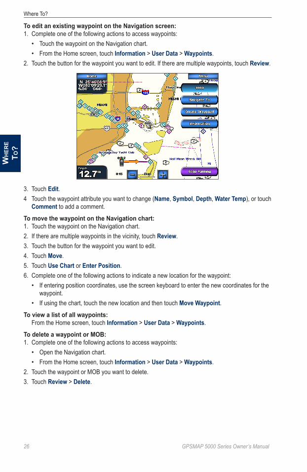
?To edit an existing waypoint on the Navigation screen:1. Complete one of the following actions to access waypoints:
Touch the waypoint on the Navigation chart.From the Home screen, touch Information > User Data > Waypoints.
2. Touch the button for the waypoint you want to edit. If there are multiple waypoints, touch Review.
3. Touch Edit.4 Touch the waypoint attribute you want to change (Name, Symbol, Depth, Water Temp), or touch
Comment to add a comment.
To move the waypoint on the Navigation chart:1. Touch the waypoint on the Navigation chart.2. If there are multiple waypoints in the vicinity, touch Review.3. Touch the button for the waypoint you want to edit.4. Touch Move.5. Touch Use Chart or Enter Position.6. Complete one of the following actions to indicate a new location for the waypoint:
If entering position coordinates, use the screen keyboard to enter the new coordinates for the waypoint.If using the chart, touch the new location and then touch Move Waypoint.
To view a list of all waypoints: From the Home screen, touch Information > User Data > Waypoints.
To delete a waypoint or MOB:1. Complete one of the following actions to access waypoints:
Open the Navigation chart.From the Home screen, touch Information > User Data > Waypoints.
2. Touch the waypoint or MOB you want to delete.3. Touch Review > Delete.
••
•
•
••

GPSMAP 5000 Series Owner’s Manual 2�
Where To?W
her
e t
o?Creating and Using RoutesYou can create and store up to 20 routes, with up to 250 waypoints each.
To create a route from your present location:1. From the Navigation chart, touch your destination. The destination is indicated by a cursor .
2. Touch Navigate To > Route To.3. Touch the location where you want to make the last turn toward your destination.4. Touch Add Turn.
5. To add additional turns, continue to touch the location where you want to make a turn (working backward from the destination) and then touch Add Turn.
6. Touch Done to finish the route or Cancel Route to delete the route.

28 GPSMAP 5000 Series Owner’s Manual
Where To?W
her
e to
?To create a route in another location:1. From the Home screen, touch Information > User Data > Routes > New Route.2. Complete one of the following actions to select the starting point of the route:
Touch Use Chart and touch the screen at the location of the first waypoint on the route. The waypoint is indicated by the cursor .Touch Use Waypoint List and select the first waypoint on the route.
3. Touch Add Turn to mark the starting point of the route.4. Touch the location of the first turn and then touch Add Turn. Repeat until the route is complete.
5. Touch Done.
To create a route using Automatic Guidance:Automatic Guidance is available with a preprogrammed BlueChart g2 Vision SD card.1. From the Navigation chart or the Where To? menu, touch your destination.2. Touch Navigate To > Guide To. Your route is calculated.
Note: To change the automatic guidance path to a route, touch the end of the path and then touch Navigate to > Route to. The automatic guidance path stays on the screen, allowing you to trace it while creating a route.
•
•
GPSMAP 5000 Series Owner’s Manual 2�
Where To?W
her
e t
o?To edit a route:1. From the Home screen, touch Information > User Data > Routes.2. Touch the route to edit.3. Touch Review > Edit Route. You can edit the route name or edit the route turns.
To delete a route:1. From the Home screen, touch Information > User Data > Routes.2. Touch the route to edit.3. Touch Review > Delete.
To bypass a waypoint on a route:1. Create a route as previously described.2. From the Navigation chart, touch the waypoint that follows the waypoint you are bypassing.3. Touch Route To.
Navigating with a Garmin AutopilotWhen you start any type of navigation (Go to, Route to, Guide to, or Follow track), if you are connected to a compatible Garmin autopilot (such as a GHP™ 10), you will be prompted to engage the autopilot.

30 GPSMAP 5000 Series Owner’s Manual
Viewing InformationVi
eWin
G
info
rm
atio
n
Viewing InformationUse the Information screen to access information about tides, currents, celestial data, user data, other boats, gauges, and video.
You can also select tide, current, and celestial information for a specific station directly from the Navigation chart. Touch near the desired station, select information, and then select either tides, Currents, Celestial, or Chart Notes.
Viewing Tide Station Information1. From the Home screen, touch Information > Tides/Currents > Tides. Information for the most-
recently viewed tide station is shown.
Tide station
Local timeCurrent tide
height
Time of next high tide
2. Select an option:Touch Nearby Stations to view other stations close to the one you selected.Touch Change Date > Manual to view tide information for a different date.
Viewing Current Information Note: You must use a BlueChart g2 Vision card to view Current Station information.
Use the Currents screen to view information for currents.1. From the Home screen, touch Information > Tides/Currents > Currents. Information for the
most-recently viewed current station is shown.
Current station
Current level at local time
••
GPSMAP 5000 Series Owner’s Manual 3�
Viewing InformationV
ieWin
G in
for
matio
n
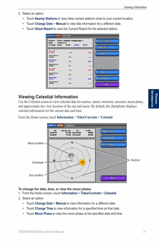
2. Select an option:Touch Nearby Stations to view other current stations close to your current location.Touch Change Date > Manual to view tide information for a different date.Touch Show Report to view the Current Report for the selected station.
Viewing Celestial InformationUse the Celestial screen to view celestial data for sunrise, sunset, moonrise, moonset, moon phase, and approximate sky view location of the sun and moon. By default, the chartplotter displays celestial information for the current date and time.
From the Home screen, touch information > tides/Currents > Celestial.
Moon position
Sun position
OverheadHorizon
To change the date, time, or view the moon phase:1. From the Home screen, touch Information > Tides/Currents > Celestial.2. Select an option:
Touch Change Date > Manual to view information for a different date.Touch Change Time to view information for a specified time on that date.Touch Moon Phase to view the moon phase at the specified date and time.
•••
•••
32 GPSMAP 5000 Series Owner’s Manual
Viewing InformationVi
eWin
G
info
rm
atio
n
Viewing User Data1. From the Home screen, touch Information > User Data.2. Select an option:
Touch Waypoints to display a list of all saved waypoints (page 25).Touch Routes to display a list of saved routes (page 27).Touch Tracks to view and manage tracks (page 14).Touch Data Transfer to transfer waypoints, routes, and tracks to and from an SD card or network.Touch Clear User Data to erase all user waypoints, routes, and tracks.
To copy or merge MapSource® data to your chartplotter:1. Insert an SD card into your chartplotter to allow it to place a file on the SD card. This file provides
information to MapSource to format its data. This only needs to be done the first time you copy or merge MapSource data to your chartplotter from a specific SD card.
2. Check your MapSource version on your computer by clicking Help > About MapSource. If the version is older than 6.12.2, update to the most current version by clicking Help > Check for Software Updates, or check the Garmin Web site at www.garmin.com.
3. Insert the SD card into an SD card reader that is attached to the computer.4. From within MapSource, click on Transfer > Send to Device.5. Select the drive for the SD card reader and the types of data you want to copy to your
chartplotter.6. Click Send.7. Insert the SD card into your chartplotter.8. From the Home screen on your chartplotter, touch Information > User Data > Data Transfer >
Card.9. Complete one of the following:
Touch Merge From Card to transfer data from the SD card to the chartplotter and combine it with existing user data.Touch Replace From Card transfer data from the SD card to the chartplotter and overwrite existing user data on the chartplotter.
10. Touch the file name from the list.11. Touch Merge from Card or Replace from Card.
To transfer waypoints, routes, and tracks to an SD card:1. Insert an SD card into the SD card slot on the front of the chartplotter.2. From the Home screen, touch Information > User Data > Data Transfer > Card > Save To
Card.3. Complete one of the following actions to indicate the name of the new file:
Select the file name from the list.Touch Add New File to create a new file. Enter the file name using the on-screen keyboard and touch Done.
4. Touch Save To Card to save waypoints, routes, and tracks to the SD card. The file name is saved with an .ADM extension.
To transfer waypoints, routes, and tracks from an SD card:1. Insert an SD card into the SD card slot on the front of the chartplotter.2. From the Home screen, touch Information > User Data > Data Transfer > Card.
••••
•
•
•
••

GPSMAP 5000 Series Owner’s Manual 33
Viewing InformationV
ieWin
G in
for
matio
n
3. Select an option to indicate how existing data on the chartplotter is handled:Touch Merge From Card to transfer data from the SD card to the chartplotter and combine it with existing user data.Touch Replace From Card transfer data from the SD card to the chartplotter and overwrite existing user data on the chartplotter.
4. Touch the file name in the list.5. Touch Merge from Card or Replace from Card.
To copy the built-in maps to an SD card:1. Insert an SD card into the SD card slot on the front of the chartplotter.2. From the Home screen, touch Information > User Data > Data Transfer > Card.3. Touch Copy Built-In Map to copy the maps loaded onto your chartplotter to the SD card.
To transfer waypoints, routes, and tracks to or from a network:1. Connect the chartplotter to a Garmin Marine Network using the network port on the back of the
chartplotter and a Garmin network cable.2. From the Home screen, touch Information > User Data > Data Transfer > Network.3. Select an option to indicate how data is handled:
Touch Clone User Data to transfer data from the chartplotter to the other chartplotters connected to the network. Existing data is overwritten on those chartplotters.Touch Merge User Data to transfer data between all the chartplotters connected to the network. Unique data is combined with existing data on every chartplotter.
To back up data to a computer:1. Insert an SD card into the SD card slot on the front of the chartplotter.2. From the Home screen, touch Information > User Data > Data Transfer > Card > Save to
Card.3. Complete one of the following actions to indicate the name of the file to be backed up:
Select the file name from the list.Touch Add New File to create a new file. Enter the file name using the on-screen keyboard and touch Done.
4. Select Save To Card. The file name is saved with an .ADM extension.5. Remove the SD card from the chartplotter and insert it into an SD card reader attached to a
computer.6. From Windows® Explorer, open the Garmin\UserData folder on the SD card.7. Copy the backup file on the card and paste it to any location on the computer.
To restore backup data to your chartplotter:1. Copy a backup file from your computer to an SD card in a folder named Garmin\UserData.2. Insert the SD card into your chartplotter.3. From the Home screen on your chartplotter, touch Information > User Data > Data Transfer >
Card > Replace From Card.
To delete all waypoints, routes, and tracks:1. From the home screen on your chartplotter, touch Information > User Data > Clear User Data.2. Select Waypoints, Routes, Saved Tracks, or All.3. Select OK or Cancel.
•
•
•
•
••

3� GPSMAP 5000 Series Owner’s Manual
Viewing InformationVi
eWin
G
info
rm
atio
n
Viewing the DSC List Note: Your chartplotter must be connected to a VHF radio that supports DSC (Digital Selective Calling) in order to view the DSC List.
The DSC List is a log of the most-recent DSC calls and other DSC contacts you have entered. The DSC List can contain up to 100 entries. The DSC List shows the most-recent call from a boat. If a second call is received from the same boat, it replaces the first call in the Call List. For more information on DSC, see page 55. To view the DSC List, from the Home screen, touch Information > DSC List.
Viewing Gauges Note: You must be connected to a NMEA (National Marine Electronics Association) 2000 network capable of sensing engine data to view the gauges. See the GPSMAP 4000/5000 Series Installation Instructions for details.
From the Home screen, touch Information > Dashboard Gauges.
To select analog or digital gauges: Note: For more than two engines, you can only use the digital gauges. For one or two engines, you can switch between analog and digital gauges.
1. To view the Gauges from the Home screen, touch Information > Dashboard Gauges > Engine > Menu.
2. Select Digital or Analog.
Viewing Fuel Gauges Note: To view fuel information, your chartplotter must be connected to an external fuel sensor, such as the Garmin GFS™ 10.
From the Home screen, touch Information > Dashboard Gauges > Fuel. Fuel flow for each engine, total fuel flow, fuel level in each tank, total fuel remaining, fuel economy, engine trim, boat speed, engine RPM, and the range for your boat are displayed.
To synchronize your fuel gauges with your fuel:1. From the Home screen touch Information > Dashboard Gauges > Fuel.2. Touch Menu.3. Select an option:
Fill Up All Tanks—select when your tank is full. An estimate of the total fuel is shown. Adjust if necessary.
•
GPSMAP 5000 Series Owner’s Manual 35
Viewing InformationV
ieWin
G in
for
matio
n
Add Fuel To Boat—select when you have added less than a full tank. An estimate of the fuel added is shown. Adjust if necessary.Set Total Fuel Onboard—select to specify the total fuel in your tanks.Fuel Economy—select either GPS Speed or Water Speed (using data from a speed wheel) for the fuel economy calculation.
Viewing VideoYour chartplotter can display video if you are connected to a video source (or sources) using the supplied video cable. See the GPSMAP 4000/5000 Series Installation Instructions for details.From the Home screen, touch Information > Video.Touch Menu to setup the following:
Source—selects the video device (Video 1 or Video 2) that displays the video. If you have two video sources and wish to alternate between the two, touch Alternate to define the amount of time each video screen is displayed.Aspect—switches between the standard aspect ratio and a stretched aspect ratio. The video cannot be stretched beyond the dimensions provided by the connected video device, and may not fill the entire of the GPSMAP 5212/5215.Brightness—adjusts the brightness of the video feed up or down. Touch Auto to allow the chartplotter to automatically adjust the brightness.Saturation—adjusts the color saturation up or down. Touch Auto to allow the chartplotter to automatically adjust the saturation.Contrast—adjusts the contrast up or down. Touch Auto to allow the chartplotter to automatically adjust the contrast.Standard—selects the video format used by the source (PAL or NTSC). Touch Auto to let the chartplotter automatically select the source format.
•
••
•
•
•
•
•
•

3� GPSMAP 5000 Series Owner’s Manual
Configuring the DeviceC
on
fiG
Ur
inG
the
deV
iCe
Configuring the DeviceUse the Configure screen to configure chartplotter settings.
Configuring System SettingsFrom the Home screen, touch Configure > System.
Simulator—turn Simulator Mode on or off. Touch Setup to set Simulator options. (If you set the chartplotter into a Store Demonstration mode during the initial chartplotter setup, this setting is named Demo.)
auto Power Up (GPSMAP 5215 only)—turn Auto Power Up on or off. When on is selected, the chartplotter automatically turns on whenever power is applied. When off is selected, the chartplotter must be turned on with the Power key.
Note: If Auto Power Up is on and the chartplotter is turned off using the Power key, and power is removed and then reapplied within less than 2 minutes, you may have to press the Power key to restart the chartplotter.
Beeper/Display—set Beeper options, Backlight, and Color Mode.
Beeper—touch Beeper to set when the chartplotter makes audible sounds. The settings are off, alarms only (default), and Key and alarm (keys and alarms).Backlight—touch Backlight to adjust the intensity of the backlight. Touch auto to allow the chartplotter to automatically adjust the backlight based on ambient light.Color Mode—touch Color Mode to select Day Colors or Night Colors, or touch auto to allow the chartplotter to adjust the colors.Screenshot Capture—turn the screenshot capture feature on or off (page 68).
GPS—view GPS satellites.
System information—view system information, restore factory settings, view the status of networked devices (page 43), and display the event log. The event log displays a list of system events. Select the event to view additional information. The Save to Card option is provided as a troubleshooting tool; a Garmin Product Support representative may ask you to use this to retrieve data about the marine network.
Radar Diagnostics (if radar is connected)—a troubleshooting tool used by installers.
Changing the System Language1. From the Home screen, touch Configure > Preferences > Language.2. Select the language.
Configuring Navigation PreferencesFrom the Home screen, touch Configure > Preferences > Navigation.
Route Labels—for saved routes, this determines whether route turns are indicated by number (Turn 1, Turn 2, and so on) or by waypoint name, or whether the description of turns is hidden.
turn transition—set how much time or how far before a turn in a route that you transition to the next leg. Raising this value can help improve the accuracy of the autopilot when navigating a route or automatic-guidance line with many frequent turns or at higher speeds. For straighter routes or slower speeds, lowering this value can improve autopilot accuracy.
•
•
•
•
GPSMAP 5000 Series Owner’s Manual 3�
Configuring the DeviceC
on
fiGU
rin
G th
e deViC
e
Speed Sources—specify the sensor used for Wind numbers and Fuel Economy. Touch Wind or Fuel economy to toggle between Water (from a water-speed sensor) and GPS (from the calculated GPS speed).
auto Guidance—sets the Automatic Guidance parameters for your boat:
Safe Depth—sets the minimum depth (chart depth datum) to allow when calculating an automatic guidance path. A safe depth of less than one meter is not allowed when using Automatic Guidance.Safe Height—sets the minimum height (chart height datum) of a bridge that your boat can safely travel under.Shoreline Distance—set how close you want to travel near the shore: Nearest, Near, Normal, Far, or Farthest. This is used by the automatic guidance calculation to determine how close to the shoreline you want the automatic-guidance line to be. Changing this while navigating an automatic-guidance line will recalculate the path.
Configuring Units of MeasureFrom the Home screen, touch Configure > Preferences > Units.
System Units—global setting that defines individual units of measure at the same time. Statute (mh, ft, ºF), Metric (kh, m, ºC), Nautical (kt, ft, ºF), or Custom. Touch Custom to individually define units of measure for:
Depth—individually set the units of measure for depth to Feet, Fathoms, or Meters. temperature—individually set the units of measure for temperature to Fahrenheit (ºF) or Celsius (ºC).
Note: You must be receiving NMEA Sonar depth data or using a Garmin sounder module to view depth and temperature information.
Distance—individually set the units of measure for distance readings (Miles, Kilometers, or Nautical Miles).Speed—individually set the units of measure for speed readings (Miles Per Hour, Kilometers Per Hour, or Knots).elevation—individually set the units of measure for elevation readings (Feet or Meters).Volume—individually set the units of measure for volume readings (Liters, US Gallons, or UK Gallons).Pressure—individually set the units of measure for gauge (kPa or psi) and atmospheric (Millibars or inches of Mercury) pressure readings.
Heading—set the reference used in calculating heading information.
auto Mag Var (Automatic Magnetic Variation)—automatically set the magnetic declination for your location.true—set true north as the heading reference.Grid—set grid north as the heading reference (000º).User Mag Var—set the magnetic variation value.
Position Format—set the coordinate system in which a given location reading appears. Do not change the position format unless you are using a map or chart that specifies a different position format.
•
•
•
••
•
•
••
•
•
•••
38 GPSMAP 5000 Series Owner’s Manual
Configuring the DeviceC
on
fiG
Ur
inG
the
deV
iCe
Map Datum—set the coordinate system in which the map is structured. The default setting is WGS 84. Do not change the map datum unless you are using a map or chart that specifies a different position format.
time—set the time options.
time Format—select 12-hour, 24-hour, or UtC time format.time Zone—set the time zone displayed for time readings.Daylight Saving time—select off, on, or auto. The auto setting automatically turns daylight saving time on or off, depending on the time of year.
Configuring Communications SettingsFrom the Home screen, touch Configure > Communications.
NMea 0183 Setup—enable or disable NMEA 0183 output sentences for sounder, route, system, and Garmin NMEA settings.
Port types—configure the input/output format for each port to use when connecting your chartplotter to external NMEA devices, a computer, or other Garmin devices. NMea Std. supports the input or output of standard NMEA 0183 data, DSC, and sonar NMEA input support for the DPT, MTW, and VHW sentences. NMea High Speed supports the input or output of standard 0183 data for most AIS receivers. The Garmin option supports the input or output of Garmin-proprietary data for interfacing with Garmin software.output Sentences—configure how the chartplotter sees NMEA 0183 output sentences. See page 69 for information on configuring these sentences.Posn. Precision—adjust the number of digits (two Digits, three Digits, or Four Digits) to the right of the decimal point for transmission of NMEA output.Waypoint iDs—determine how the chartplotter outputs waypoint identifiers (Names or Numbers).Defaults—reset NMEA 0183 settings to their default settings.Diagnostics—a tool used by installers to verify that NMEA 0183 data is being sent across the system.
NMea 2000 Setup—View and configure the devices connected to the NMEA 2000 network and set bridging to on, off, or auto.
Device List—lists the NMEA 2000 devices on your network. If a NMEA 2000 device has configuration options or settings, select the device for a list of options.output Bridging—Output bridging occurs when a chartplotter takes NMEA 0183 data it receives from any source, formats it into NMEA 2000 data, and then sends it over the NMEA 2000 bus. Touch on or off to enable or disable this function for the chartplotter. Touch auto to allow the chartplotters on the network to negotiate with each other to determine which chartplotter will perform this function. Only one chartplotter on the network will bridge NMEA 0183 data over the NMEA 2000 bus at a time.
Marine Network—Review all connected Garmin Marine Network devices (page 43).
Wireless Devices—Allow wireless devices, such as a remote control or optical mouse to communicate with the chartplotter.
Preferred Sources—Assign a preferred device when more than one source is available for the same function.
•••
•
•
•
•
••
•
•
GPSMAP 5000 Series Owner’s Manual 3�
Configuring the DeviceC
on
fiGU
rin
G th
e deViC
e
Setting AlarmsYou can set the chartplotter to sound an audible alarm when certain conditions are met. By default, all alarms are turned off.
To set an alarm:1. From the Home screen, touch Configure > Alarms.2. Touch an alarm category.3. Touch On to turn the alarm on and then use the touch screen keyboard to specify alarm
information.
Setting Navigation AlarmsFrom the Home screen, touch Configure > alarms > Navigation.
arrival—set an alarm to sound when you are within a specified distance or time from a turn or destination waypoint.
type—select whether you want arrival alarms to sound only when nearing destinations or when nearing turns and destinations. Set to off to disable arrival alarms.activation—select whether the arrival alarm triggers based on time to arrival or based on distance to arrival.Change time/Change Distance—if you have Activation set to time, touch Change time to set the number of minutes before arrival that the alarm should sound. If you have Activation set to Distance, touch Change Distance to set the distance before arrival that the alarm should sound. Use the on-screen keyboard to change the time or distance.
anchor Drag—sets an alarm to sound when you exceed a specified drift distance.
off Course—sets an alarm to sound when you are off course by a specified distance.
Setting System AlarmsFrom the Home screen, touch Configure > alarms > System.
Clock—sets an alarm using the system (GPS) clock. The chartplotter must be on for the clock alarm to work.
Battery—sets an alarm to sound when the battery reaches a specified low voltage.
GPS accuracy—sets an alarm to sound when the GPS location accuracy falls outside the user-determined value.
Setting Sonar Alarms Note: You must have an optional sonar module and a transducer connected using NMEA 0183 or the Garmin Marine Network to receive sonar information.
From the Home screen, touch Configure > alarms > Sonar.
Shallow Water—set an alarm to sound when the depth is less than the specified value.
Deep Water—set an alarm to sound when the depth is greater than the specified value.
Water temp—sets an alarm to sound when the transducer reports a temperature that is 2°F (1.1°C) above or below the specified temperature.
•
•
•

�0 GPSMAP 5000 Series Owner’s Manual
Configuring the DeviceC
on
fiG
Ur
inG
the
deV
iCe
Fish—sets an alarm to sound when the chartplotter detects a suspended target of the specified symbols.
—sounds an alarm for all fish sizes.
—sounds an alarm for medium and large fish only.
—sounds an alarm for large fish only.
Setting Weather Alarms Note: You must have a subscription to XM WX Weather and a Garmin XM WX Weather receiver (such as a GDL 30A) connected using the Garmin Marine Network to view weather information. Refer to page 53 for more information.
From the Home screen, touch Configure > alarms > Weather. Turn the following alarms on or off:
MarineTornadoSevere StormFloodFlash Flood
Setting the Total Fuel Onboard Alarm Note: To receive fuel-level information, your chartplotter must be connected to an external fuel sensor, such as the Garmin GFS 10.
You can configure your chartplotter to sound an alarm when the total amount of remaining onboard fuel reaches the level you specify.
To enable the Total Fuel Onboard alarm and set the fuel alarm level:1. From the Home screen, touch Configure > Alarms > Fuel > Total Fuel Onboard > On.2. Use the on-screen keyboard to indicate the fuel level at which the alarm should sound.
To disable the Total Fuel Onboard alarm:From the Home screen, touch Configure > Alarms > Fuel > Total Fuel Onboard > Off.
Configuring My BoatFrom the Home screen, touch Configure > My Boat.
Keel offset—offsets the surface reading for the depth of a keel, making it possible to measure depth from the bottom of the keel instead of from the transducer location. Enter a positive number to offset for a keel. You can enter a negative number to compensate for a large vessel that may draw several feet of water.
temp offset—set the temperature offset for the temperature sensor of your transducer.
Calibrate Water Speed—calibrates a speed-sensing device. Follow the on-screen directions for calibration. If you do not have a speed-sensing transducer, this menu does not appear.
Note: If the boat is not moving fast enough or the speed sensor is not registering a speed, a “Speed too Low” message appears. Touch oK and safely increase boat speed. If you get the message again, stop the boat and make sure the speed-sensor wheel is not stuck. If the wheel turns freely, check the cable connections. If you continue to get the message, contact Garmin Product Support.
•••••
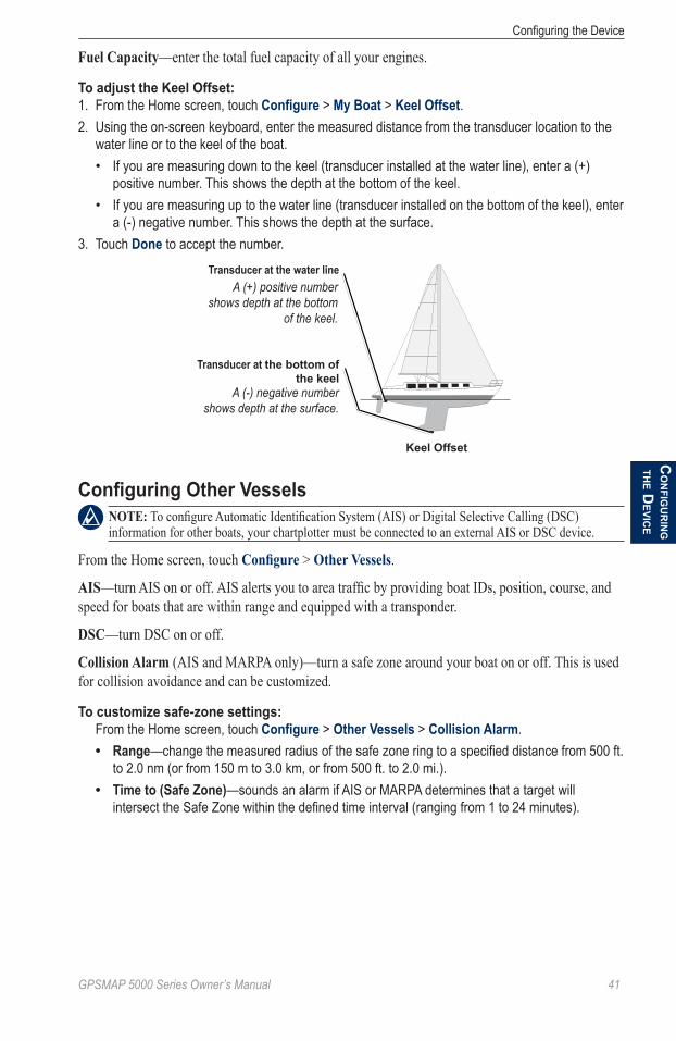
GPSMAP 5000 Series Owner’s Manual ��
Configuring the DeviceC
on
fiGU
rin
G th
e deViC
e
Fuel Capacity—enter the total fuel capacity of all your engines.
To adjust the Keel Offset:1. From the Home screen, touch Configure > My Boat > Keel Offset.2. Using the on-screen keyboard, enter the measured distance from the transducer location to the
water line or to the keel of the boat.If you are measuring down to the keel (transducer installed at the water line), enter a (+) positive number. This shows the depth at the bottom of the keel.If you are measuring up to the water line (transducer installed on the bottom of the keel), enter a (-) negative number. This shows the depth at the surface.
3. Touch Done to accept the number.
Transducer at the water line
Transducer at the bottom of the keel
Keel Offset
A (+) positive number shows depth at the bottom
of the keel.
A (-) negative number shows depth at the surface.
Configuring Other Vessels Note: To configure Automatic Identification System (AIS) or Digital Selective Calling (DSC) information for other boats, your chartplotter must be connected to an external AIS or DSC device.
From the Home screen, touch Configure > other Vessels.
aiS—turn AIS on or off. AIS alerts you to area traffic by providing boat IDs, position, course, and speed for boats that are within range and equipped with a transponder.
DSC—turn DSC on or off.
Collision alarm (AIS and MARPA only)—turn a safe zone around your boat on or off. This is used for collision avoidance and can be customized.
To customize safe-zone settings: From the Home screen, touch Configure > Other Vessels > Collision Alarm.
Range—change the measured radius of the safe zone ring to a specified distance from 500 ft. to 2.0 nm (or from 150 m to 3.0 km, or from 500 ft. to 2.0 mi.).Time to (Safe Zone)—sounds an alarm if AIS or MARPA determines that a target will intersect the Safe Zone within the defined time interval (ranging from 1 to 24 minutes).
•
•
•
•
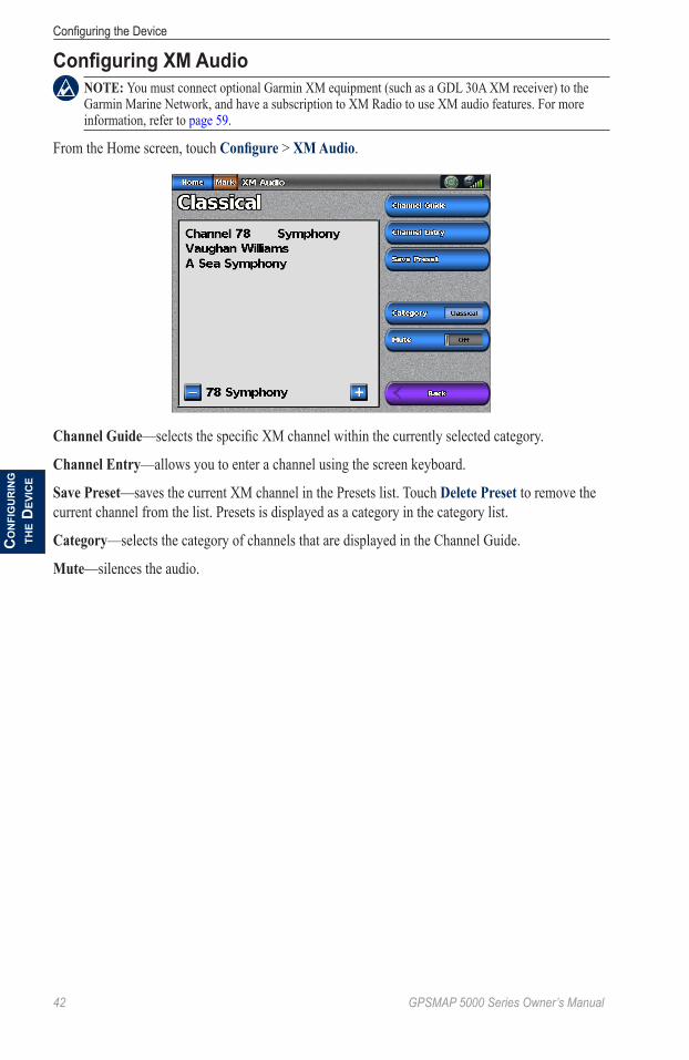
�2 GPSMAP 5000 Series Owner’s Manual
Configuring the DeviceC
on
fiG
Ur
inG
the
deV
iCe
Configuring XM Audio Note: You must connect optional Garmin XM equipment (such as a GDL 30A XM receiver) to the Garmin Marine Network, and have a subscription to XM Radio to use XM audio features. For more information, refer to page 59.
From the Home screen, touch Configure > XM audio.
Channel Guide—selects the specific XM channel within the currently selected category.
Channel entry—allows you to enter a channel using the screen keyboard.
Save Preset—saves the current XM channel in the Presets list. Touch Delete Preset to remove the current channel from the list. Presets is displayed as a category in the category list.
Category—selects the category of channels that are displayed in the Channel Guide.
Mute—silences the audio.

GPSMAP 5000 Series Owner’s Manual �3
Using the Marine Networkm
ar
ine
netW
or
k
Using the Marine NetworkThe Garmin Marine Network allows you to share data from Garmin peripheral devices to Garmin chartplotters quickly and easily. You can connect your GPSMAP 4000 series chartplotter to a Garmin Marine Network to receive data from and share data with other Marine Network-compatible devices and chartplotters. With the Garmin Marine Network, you can:
Share GPS data from a GPS 17 or GPS 17x antenna wired to one chartplotter with every chartplotter connected to the Garmin Marine Network.Share NMEA 0183 data from devices wired to one chartplotter, with every chartplotter connected to the Marine Network.
Note: Both the GPS 17 or GPS 17X and any NMEA 0183 devices must be connected to the same chartplotter to achieve the best results when sharing data over the Garmin Marine Network.
Note: If you are using a GSD 21 wired to a GPSMAP 3006/3010 chartplotter, the data is shared with any GPSMAP 5000 series chartplotters connected to the network. All GSD 21 settings must be configured on the GPSMAP 3006/3010 chartplotter. A GSD 21 cannot be wired to a GPSMAP 5000 series chartplotter.
Share data from Garmin Marine Network devices connected to any chartplotter in the Marine Network or to a GMS 10 Marine Network Port Expander, with every other chartplotter connected to the Marine Network. These devices include:
GSD 22 Digital Sounder—provides sonar data when connected to the Garmin Marine Network and an appropriate transducer. Sonar data is shared by all chartplotters on the network.GMR 21/41 Radome, GMR 18 Radome, and GMR 404/406 open array Radar—provides radar data when connected to the Garmin Marine Network. Radar data is shared by all chartplotters on the network.GDL 30/GDL 30a—provides XM WX weather and XM Radio data when connected to the Garmin Marine Network. XM WX weather data is shared by all chartplotters on the network. Connect the GDL 30A (the GDL 30 device provides only weather) to the audio input source on your boat to listen to XM audio. The station can be changed by any chartplotter on the network.
Note: Currently, the XM Satellite service is only available in North America. The GDL 30/30A functions only when used in North America.
Share BlueChart g2 Vision cartography data from an SD card inserted in one GPSMAP 4000 or GPSMAP 5000 series chartplotter with every GPSMAP 4000/5000 series chartplotter connected to the Marine Network.
Note: BlueChart g2 Vision cartography is only compatible with GPSMAP 4000 and GPSMAP 5000 series chartplotters. Previous Garmin Marine Network-compatible chartplotter models (such as the GPSMAP 3010) can be connected to your network, but they cannot share BlueChart g2 Vision data.
Transfer waypoint, route, and track information from one chartplotter connected to the Garmin Marine Network to every other chartplotter connected to the network. The data can be cloned from one chartplotter to every other connected chartplotter, or the data can be merged and shared with every connected GPSMAP 4000 and GPSMAP 5000 series chartplotter.
•
•
•
◦
◦
◦
•
•
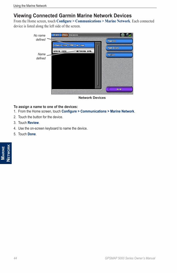
�� GPSMAP 5000 Series Owner’s Manual
Using the Marine Networkm
ar
ine
net
Wo
rk
Viewing Connected Garmin Marine Network DevicesFrom the Home screen, touch Configure > Communications > Marine Network. Each connected device is listed along the left side of the screen.
Network Devices
Name defined
No name defined
To assign a name to one of the devices:1. From the Home screen, touch Configure > Communications > Marine Network.2. Touch the button for the device.3. Touch Review.4. Use the on-screen keyboard to name the device.5. Touch Done.

GPSMAP 5000 Series Owner’s Manual �5
Using RadarU
SinG
ra
da
r
Using RadarWhen you connect your chartplotter to an optional Garmin marine radar such as a GMR 404/406 or a GMR 18/24, you can view more information about your surroundings. The radar connects through the Garmin Marine Network and shares radar data with all networked chartplotters.
The Garmin Marine Radar transmits a narrow beam of microwave energy as it rotates in a 360 pattern. When the transmitted energy contacts a target, some of that energy is reflected back to the radar.
WaRNiNG: The marine radar transmits microwave energy that has the potential to be harmful to humans and animals. Before beginning radar transmission, verify that the area around the radar is clear. The radar transmits a beam approximately 12° above and below a line extending horizontally from the center of the radar. Avoid looking directly at the radar, because the eyes are the most susceptible part of the body.
To turn on the radar:1. Power on the network. The radar warms up and a countdown is provided to alert you when the
radar is ready.
Note: As a safety feature, the radar enters standby mode after it warms up. This gives you an opportunity to verify that the area around the radar is clear before beginning radar transmission. The microwave energy transmitted by the radar can potentially be harmful to humans and animals.
2. From the Home screen, touch Radar > Cruising. The “Ready to Transmit” message appears.3. Complete one of the following actions:
Touch Menu.Press and release the Power key on the chartplotter. Do not hold the key, or you may shut down the chartplotter.
4. Touch Transmit Radar. A “Spinning Up” message appears for a few moments, then the radar begins painting an image.
To turn off the radar:1. Complete one of the following actions:
Touch Menu.Press and release the Power key on the chartplotter. Do not hold the key, or you may shut down the chartplotter.
2. Touch Radar to Standby.
••
••

�� GPSMAP 5000 Series Owner’s Manual
Using RadarU
Sin
G
ra
da
r
Using Cruising ModeCruising mode is the standard radar operation. If you switch from Sentry mode (see Using Sentry Mode) to Cruising mode, the antenna will go into full-time transmission and will disable any guard zones.
To enable Cruising mode, touch Radar > Cruising.
Use the Cruising screen to view a full-screen image of the gathered radar information. Your position is in the center of the screen, and the rings provide distance measurements.
Range rings
Heading lineZoom scale
Distance between rings
The zoom scale represents the distance from your position (the center) to the outermost ring. Each ring represents an even division of the zoom scale. For example, if the zoom scale is set at three miles, each ring represents one mile from the center out. Adjust the zoom scale using the and buttons.
Using Sentry Mode Note: When Sentry mode is enabled, all MARPA targets are cancelled, and you cannot acquire MARPA targets until you exit Sentry mode.
Sentry mode allows you to put the radar antenna into timed-transmit mode, in which you can configure a transmit and standby cycle. You can also enable a guard zone in Sentry mode, which identifies a safe zone around your boat. An alarm sounds when a radar object enters this zone.
To enable Sentry mode, touch Radar > Sentry.
To enable timed-transmit mode:From the Home screen, touch Radar > Sentry > Menu > Sentry Setup > Timed Xmit.
To set the standby and transmit times:1. From the Radar screen, touch Menu > Sentry Setup.2. Touch Timed Xmit if it is set to off, and then select Stdby Time or Xmit Time.3. Enter the time in minutes using the on-screen keyboard and then touch Done.

GPSMAP 5000 Series Owner’s Manual ��
Using RadarU
SinG
ra
da
r
To enable the guard zone:From the Home screen, touch Radar > Sentry > Menu > Sentry Setup > Enable Guard Zone.
To adjust the guard zone boundaries:1. While the guard zone is on, from the Radar screen, touch Menu > Sentry Setup > Adjust Guard
Zone > Move Guard Zone.2. Select from the following options:
Corner 1 (and Corner 2): Defines a guard zone that does not completely encompass the boat. Touch Corner 1, and then touch the point on the screen at which you want the first corner of the guard zone. Repeat this with Corner 2.Circular: Joins the guard zone to completely encompass the boat. Use Corner 1 or Corner 2 to adjust the size.
Corner � Corner 2 Circular
Radar Targeting Note: MARPA requires the use of a heading sensor. The heading sensor must output the NMEA 0183 sentence HDM or HDG.
1. From the Radar screen, touch the target location to begin targeting. As you move the target over objects on the radar, target options appear along the right side of the screen.
Cruising Screen - Targeting
Heading line
Target
Target options
2. Select an option:Select Create Waypoint to mark a waypoint at the targeted object or location.Select Acquire Target to assign a MARPA (Mini Automatic Radar Plotting Aid) tag to the targeted object.Select Drop VRM/EBL to set the Variable Range Marker (VRM) and Electronic Bearing Line (EBL) to measure range and bearing to a target.
•
•
••
•
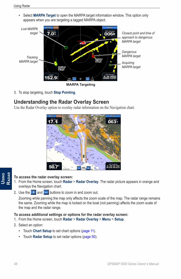
�8 GPSMAP 5000 Series Owner’s Manual
Using RadarU
Sin
G
ra
da
r
Select MARPA Target to open the MARPA target information window. This option only appears when you are targeting a tagged MARPA object.
MARPA Targeting
Acquiring MARPA target
Tracking MARPA target
Lost MARPA target
Dangerous MARPA target
Closest point and time of approach to dangerous MARPA target
3. To stop targeting, touch Stop Pointing.
Understanding the Radar Overlay ScreenUse the Radar Overlay option to overlay radar information on the Navigation chart.
To access the radar overlay screen:1. From the Home screen, touch Radar > Radar Overlay. The radar picture appears in orange and
overlays the Navigation chart.2. Use the and buttons to zoom in and zoom out.
Zooming while panning the map only affects the zoom scale of the map. The radar range remains the same. Zooming while the map is locked on the boat (not panning) affects the zoom scale of the map and the radar range.
To access additional settings or options for the radar overlay screen:1. From the Home screen, touch Radar > Radar Overlay > Menu > Setup.2. Select an option:
Touch Chart Setup to set chart options (page 11).Touch Radar Setup to set radar options (page 50).
•
••
GPSMAP 5000 Series Owner’s Manual ��
Using RadarU
SinG
ra
da
r
Obtaining Optimal Radar Display PerformanceThe gain controls the sensitivity of the radar receiver. The default setting for the gain, Auto, adjusts the gain automatically to provide the best performance.
To adjust the gain:1. From the Radar screen, touch Menu > Gain.2. Select an option to adjust the gain:
To return the gain to the default setting, touch Auto.To manually adjust the gain, touch Up or Down.
Reducing Unwanted NoiseThere are several options that adjust the gain to help reduce unwanted clutter on the radar screen.1. From the Radar screen, touch Menu > Noise Rejection.2. Select an option:
Touch Rain Clutter to adjust the gain for unwanted clutter caused by rain at close ranges. Touch Up or Down to adjust the rain clutter sensitivity.Touch Sea Clutter to adjust the gain for clutter caused by choppy sea conditions. Touch Rough, Medium, or Calm. Touch Up or Down to manually adjust the sea clutter sensitivity.Touch Cross Talk to filter out interference caused by another radar operating in close proximity.Touch FTC (Fast Time Constant) to reduce unwanted clutter caused by rain at a distance. FTC has four presets (Off, Low, Medium, or High).
Adjusting the VRM and EBLThe Variable Range Marker (VRM) and Electronic Bearing Line (EBL) tools measure range and bearing to a target. You can adjust the diameter of the VRM and the angle of the EBL.
To show or hide the VRM and EBL:The measured range and bearing are displayed in the upper-left corner of the screen.
If the VRM and EBL are hidden, from the Radar screen, touch Menu > Show VRM/EBL.If the VRM and EBL are shown, from the Radar screen, touch Menu > Adjust VRM/EBL > Hide VRM/EBL.
To select the VRM/EBL target location:1. On the Radar screen, touch the location you want to set the VRM/EBL marker.2. Touch Drop VRM/EBL.
To adjust the VRM/EBL target location:1. From the Radar screen, touch Menu > Adjust VRM/EBL > Move VRM/EBL.2. Touch the new location where you want to set the marker.3. Touch Done.
••
•
•
•
•
••

50 GPSMAP 5000 Series Owner’s Manual
Using RadarU
Sin
G
ra
da
r
Configuring Other Vessels on the Radar ScreenYou can configure which other vessels are displayed on the radar screen. From the Radar screen, touch Menu > other Vessels.
Note: To configure Automatic Identification System (AIS) information for other boats, your chartplotter must be connected to an external AIS device.
List—display a list of AIS and MARPA threats. Touch Show to select between displaying aiS or MaRPa threats, or all threats.
Display Setup—configure how other vessels are displayed on the Radar screen.
Display Range—set the distance from your location that AIS vessels are displayed.Details—show or hide details for each vessel.Proj. Heading—set the projected heading time.
Collision alarm (AIS and MARPA only)—turn a safe zone around your boat on or off. This is used for collision avoidance, and can be customized.
To customize safe-zone settings for the Collision Alarm:1. From the Radar screen, touch Menu > Other Vessels > Collision Alarm.2. Select from the following options:
Range—change the measured radius of the safe zone ring to a specified distance from 500 ft. to 2.0 nm (or from 150 m to 3.0 km, or from 500 ft. to 2.0 mi).Time To (Safe Zone)—sounds an alarm if AIS or MARPA determines that a target will intersect the Safe Zone within the defined time interval (ranging from 1 to 24 minutes).
Advanced Radar ConfigurationTo access advanced radar settings, from the Radar screen, touch Menu > Radar Setup.
Rotation Speed (GMR 18/24/404/406 series models only)—set the rotation speed of your radar to Normal Speed or High Speed. High Speed increases the speed at which the antenna rotates, which increases the speed at which the screen updates.
Front of Boat—offset the front of the boat if you mount the radar at an angle.
Data Bars—show or hide cruising, navigation, fishing, fuel, or sailing numbers (page 7).
appearance—configure radar display options.
Color Scheme—change the colors used for the radar display.orientation—change the perspective of the radar display.Look-ahd Spd—shift your current location toward the bottom of the screen as your speed increases. Enter your top speed for the best results.Heading Line—show or hide a line in the direction of travel.Rings—show or hide the radar range rings.Nav Lines—show or hide a colored line that indicates the route you are currently navigating.Waypoints—show or hide waypoints that are within the range displayed on the Radar screen. Touch Navigation only to display only waypoints associated with the currently active route.
•••
•
•
•••
••••
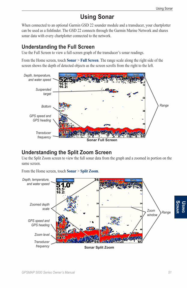
GPSMAP 5000 Series Owner’s Manual 5�
Using SonarU
SinG
So
na
r
Using SonarWhen connected to an optional Garmin GSD 22 sounder module and a transducer, your chartplotter can be used as a fishfinder. The GSD 22 connects through the Garmin Marine Network and shares sonar data with every chartplotter connected to the network.
Understanding the Full ScreenUse the Full Screen to view a full-screen graph of the transducer’s sonar readings.
From the Home screen, touch Sonar > Full Screen. The range scale along the right side of the screen shows the depth of detected objects as the screen scrolls from the right to the left.
Sonar Full Screen
Suspended target
Bottom
Depth, temperature, and water speed
GPS speed and GPS heading
Transducer frequency
Range
Understanding the Split Zoom ScreenUse the Split Zoom screen to view the full sonar data from the graph and a zoomed in portion on the same screen.
From the Home screen, touch Sonar > Split Zoom.
Sonar Split Zoom
Depth, temperature, and water speed
GPS speed and GPS heading
Transducer frequency
Zoom level
RangeZoom window
Zoomed depth scale

52 GPSMAP 5000 Series Owner’s Manual
Using SonarU
Sin
G
Son
ar
Understanding the Split Frequency ScreenUse the Split Frequency screen (dual-frequency transducer only) to view both the 50kHz and 200kHz frequencies on the same screen.
From the Home screen, touch Sonar > Split Frequency. A 200kHz frequency graph appears on the left; a 50kHz frequency graph appears on the right.
Sonar Split Frequency
Depth, temperature, and water speed
GPS speed and GPS heading
Transducer frequencies
Range
Understanding the Temp LogIf you are using a temperature-capable transducer, the Temp Log screen keeps a graphic log of temperature readings over time.1. From the Home screen, touch Sonar > Temp Log. The current temperature and depth are
shown in the upper-left corner.The temperature appears along the right side and the time elapsed appears along the bottom. The graph scrolls to the left as information is received.
2. Touch Menu to access the following scale settings:Touch Duration to set the time elapsed scale.Touch Scale to set the temperature range scale.
Transducer Temperature Log
Temperature and depth
Time elapsed
Temperature range
••

GPSMAP 5000 Series Owner’s Manual 53
Using SonarU
SinG
So
na
r
Setting Up SonarUse the Sonar Setup screen to define and adjust settings for all sonar screens.
From the Home screen, touch Sonar > Sonar Setup.
Scroll Speed—adjusts the rate at which the sonar scrolls from right to left (Ultrascroll™, Fast, Medium, or Slow). If you are using a speed-capable transducer, touch auto to have the scroll speed automatically adjust to the water speed of your boat.
Surface Noise—shows or hides the sonar returns near the surface of the water. Hide surface noise to help reduce clutter.
Depth Line—quickly reference a specific depth (Show or Hide). When Show is selected, touch and drag the line to set the depth of the reference line.
a-Scope—creates a vertical flasher along the right side of the screen (on or off).
overlay Numbers—shows or hides water temperature, battery voltage, water speed (if your transducer is capable), and navigation. If auto is selected and the transducer is capable, the data is shown.
Configuring Sonar AppearanceFrom the Home screen, touch Sonar > Sonar Setup > appearance.
Fish Symbols—sets how the sonar interprets suspended targets.
The chartplotter does not interpret the sonar return data (default). Suspended targets appear as symbols. Background sonar information appears, making the distinction between fish and structure easier.
Suspended targets appear as symbols with background information shown. The target depth of each symbol is also indicated.
Suspended targets appear as symbols. No background information appears. Suspended targets appear as symbols with no background information shown. The target depth of each symbol is indicated.
Whiteline—highlights the strongest signal from the bottom to help identify its hardness or softness.
off—(default) Whiteline is disabled.High—the most sensitive setting. Almost all strong returns are highlighted in white.Medium—many strong returns are highlighted in white.Low—the least sensitive setting. Only the strongest returns are highlighted in white.
Color Scheme—choose white (black, if using night mode colors) or blue. This affects the background on all sonar screens, but does not change the Temp Log screen.
••••

5� GPSMAP 5000 Series Owner’s Manual
Using SonarU
Sin
G
Son
ar
Advanced Sonar SettingsTo adjust advanced sonar settings, touch Menu while viewing a sonar screen.
Gain—control the sensitivity of the sonar receiver. Touch auto or touch Up or Down (or drag the adjustment bar) to manually adjust the gain. To see more detail, increase the gain. If the screen is cluttered, decrease the gain.
Pause Sonar—select to stop scrolling. Touch Create Waypoint to save the location as a waypoint, and touch Resume to continue scrolling in real time. For more information on waypoints, see page 25.
Frequency—select how the frequencies appear on screen (200kHz, 50kHz, or Dual) when using a dual frequency transducer.
Zoom—zoom in to a section of the Full screen. The zoom is off (No Zoom) by default. Three other options are available:
2x Zoom—twice the magnification. Touch Up, Down, or auto to set the depth range of the magnified area.4x Zoom—four times the magnification. Touch Up, Down, or auto to set the depth range of the magnified area.Bottom Lock—lock the zoom window to the bottom. Touch Up or Down to set the depth range of the magnified area.
Range—adjust the range of the depth scale on the right side of the screen. Touch auto or touch Up or Down (or drag the adjustment bar) to manually adjust the range.
Sonar Setup—open the Sonar Setup screen (page 53).
•
•
•
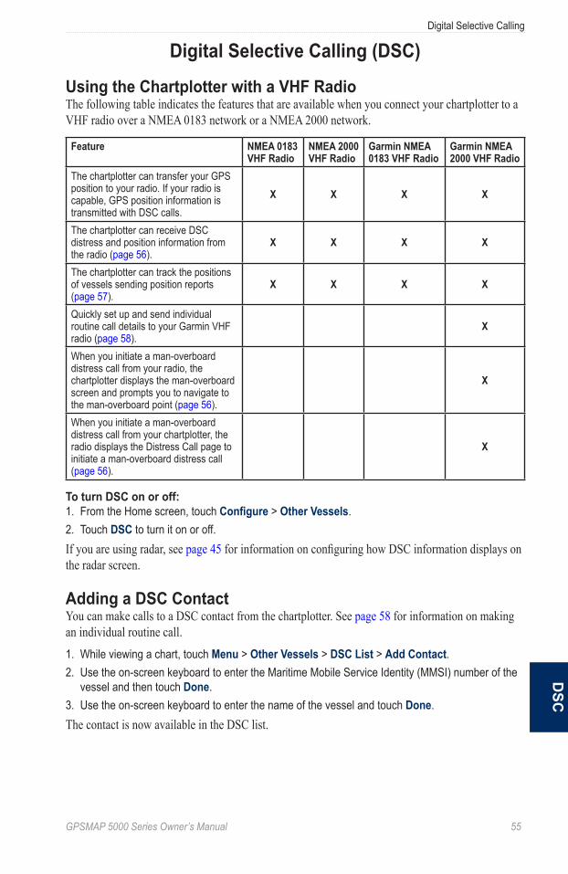
GPSMAP 5000 Series Owner’s Manual 55
Digital Selective Callingd
SC
Digital Selective Calling (DSC)
Using the Chartplotter with a VHF RadioThe following table indicates the features that are available when you connect your chartplotter to a VHF radio over a NMEA 0183 network or a NMEA 2000 network.
Feature NMEA 0183 VHF Radio
NMEA 2000 VHF Radio
Garmin NMEA 0183 VHF Radio
Garmin NMEA 2000 VHF Radio
The chartplotter can transfer your GPS position to your radio. If your radio is capable, GPS position information is transmitted with DSC calls.
X X X X
The chartplotter can receive DSC distress and position information from the radio (page 56).
X X X X
The chartplotter can track the positions of vessels sending position reports (page 57).
X X X X
Quickly set up and send individual routine call details to your Garmin VHF radio (page 58).
X
When you initiate a man-overboard distress call from your radio, the chartplotter displays the man-overboard screen and prompts you to navigate to the man-overboard point (page 56).
X
When you initiate a man-overboard distress call from your chartplotter, the radio displays the Distress Call page to initiate a man-overboard distress call (page 56).
X
To turn DSC on or off:1. From the Home screen, touch Configure > Other Vessels.2. Touch DSC to turn it on or off.If you are using radar, see page 45 for information on configuring how DSC information displays on the radar screen.
Adding a DSC ContactYou can make calls to a DSC contact from the chartplotter. See page 58 for information on making an individual routine call.1. While viewing a chart, touch Menu > Other Vessels > DSC List > Add Contact.2. Use the on-screen keyboard to enter the Maritime Mobile Service Identity (MMSI) number of the
vessel and then touch Done.3. Use the on-screen keyboard to enter the name of the vessel and touch Done.The contact is now available in the DSC list.
5� GPSMAP 5000 Series Owner’s Manual
Digital Selective Callingd
SC
Viewing the DSC ListThe DSC list is a log of the most-recent DSC calls and other DSC contacts you have entered. The DSC list can contain up to 100 entries. The DSC list shows the most-recent call from a boat. If a second call is received from the same boat, it replaces the first call in the call list.
From a chart screen, touch Menu > other Vessels > DSC List.
Receiving Distress CallsIf your Garmin chartplotter and VHF radio are connected using NMEA 0183 or NMEA 2000, your chartplotter alerts you when your VHF radio receives a DSC distress call. If position information was sent with the distress call, that information is also available and recorded with the call.
The symbol designates a distress call in the DSC List and marks the position of a vessel on the Navigation chart at the time a DSC distress call is sent.
When you receive a DSC distress call:1. Touch Review to view details about the call.2. Select from the following options:
Select Call with Radio to set up an individual routine call with the radio to call the vessel in distress (page 58). This option is only available if you are using a Garmin NMEA 2000-compatible VHF radio.Select Edit to edit the vessel name and add a comment. If your radio is tracking the position of the vessel, touch Trail to show or hide the trail line for the vessel, and touch Trail Line to change the line color.Select Clear Report to delete the call report.Select Navigate To to Go To or Route To the position sent with the distress call (page 23). The symbol marks the position of the vessel on the Navigation chart at the time a DSC distress call is sent.Select Create Waypoint to set a waypoint at the position sent with the distress call.Select Next Page or Previous Page to toggle between details related to the distress call and a Navigation chart marking the position sent with the distress call.
Man-Overboard Distress Calls Initiated from a VHF RadioWhen your Garmin chartplotter is connected to a Garmin NMEA 2000-compatible radio, and you initiate a man-overboard DSC distress call from your radio, your Garmin chartplotter displays the man-overboard screen and prompts you to navigate to the man-overboard point. If you have a Garmin autopilot system connected to the network, your chartplotter prompts you to start a Williamson’s turn to the man-overboard point.
If you cancel the man-overboard distress call on the radio, the chartplotter screen prompting you to activate navigation to the man-overboard location is no longer displayed.
Man-Overboard Distress Calls Initiated from the ChartplotterWhen your Garmin chartplotter is connected to a Garmin NMEA 2000-compatible radio and you activate navigation to a man-overboard location, the radio displays the Distress Call page to initiate a man-overboard distress call
On the radio, press and hold the DiStReSS key for at least three seconds to send the distress call.
•
•
••
••
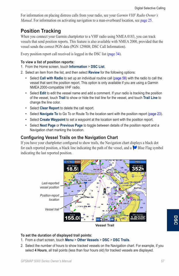
GPSMAP 5000 Series Owner’s Manual 5�
Digital Selective Callingd
SC
For information on placing distress calls from your radio, see your Garmin VHF Radio Owner’s Manual. For information on activating navigation to a man-overboard location, see page 25.
Position TrackingWhen you connect your Garmin chartplotter to a VHF radio using NMEA 0183, you can track vessels that send position reports. This feature is also available with NMEA 2000, provided that the vessel sends the correct PGN data (PGN 129808; DSC Call Information).
Every position report call received is logged in the DSC list (page 34).
To view a list of position reports:1. From the Home screen, touch Information > DSC List.2. Select an item from the list, and then select Review for the following options:
Select Call with Radio to set up an individual routine call (page 58) with the radio to call the vessel that sent the position report. This option is only available if you are using a Garmin NMEA 2000-compatible VHF radio.Select Edit to edit the vessel name and add a comment. If your radio is tracking the position of the vessel, touch Trail to show or hide the trail line for the vessel, and touch Trail Line to change the line color.Select Clear Report to delete the call report.Select Navigate To to Go To or Route To the location sent with the position report (page 23).Select Create Waypoint to set a waypoint at the location sent with the position report.Select Next Page or Previous Page to toggle between details of the position report and a Navigation chart marking the location.
Configuring Vessel Trails on the Navigation ChartIf you have your chartplotter configured to show trails, the Navigation chart displays a black dot for each reported position, a black line indicating the path of the vessel, and a Blue Flag symbol indicating the last reported position.
Vessel trail
Last-reported vessel position
Position-report location
Vessel Trail
To set the duration of displayed trail points:1. From a chart screen, touch Menu > Other Vessels > DSC > DSC Trails.2. Select the number of hours to show tracked vessels on the Navigation chart. For example, if you
select 4 Hours, all trail points (less than four hours old) for tracked vessels are displayed.
•
•
••••
58 GPSMAP 5000 Series Owner’s Manual
Digital Selective Callingd
SC
To turn trail lines off for tracked vessels:1. From a chart screen, touch Menu > Other Vessels > DSC > DSC Trails.2. Touch Off to turn trails off for every vessel.
To show or hide the trail line for a specific vessel that is sending position reports:1. From the Home screen, touch Information > DSC List.2. Select the vessel from the list, and then touch Review.3. Touch Trail to show or hide the trail for the vessel on the Navigation chart.
To change the symbol and color of the trail line for a vessel:1. From the Home screen, touch Information > DSC List.2. Select any call from that vessel from the list, and then touch Review > Edit.3. Select an option:
Touch Symbol to edit the symbol.Touch Trail Line to edit the line color.
Placing an Individual Routine CallWhen you connect your Garmin chartplotter to a Garmin VHF NMEA 2000-compatible radio, you can use the chartplotter interface to set up an individual routine call. When setting up an individual routine call from your chartplotter, you can select one of the following channels on which you want to communicate. The radio transmits this request with your call.
The selection of a DSC channel is limited to those channels that are available in all frequency bands: 6, 8, 9, 10, 13, 15, 16, 17, 67, 68, 69, 71, 72, 73, or 77.
Note: The default channel is 72. Select Channel to select a different channel from the list. If you select a different channel, the chartplotter will use that channel for subsequent calls until you call using a different channel.
To make an individual routine call:1. While viewing a chart, touch Menu > Other Vessels > DSC List.2. Select the station to call from the list.3. Touch Review > Call with Radio.4. Touch Send to send the information about the call to the radio.5. On your Garmin VHF radio, select Call.
Note: When initiating a call from the chartplotter, if the radio does not have an MMSI number programmed, the radio will not receive call information.
Calling an AIS TargetWhen you connect your Garmin chartplotter to a Garmin VHF NMEA 2000-compatible radio, you can use the chartplotter interface to set up an individual routine call to an Automatic Identification System (AIS) target. For more information on selecting a channel other than the default channel (Channel 72), see “Placing an Individual Routine Call.”
To make an individual routine call to an AIS target:1. While viewing a chart, touch an AIS target .2. Touch AIS Vessel > Call with Radio.3. Touch Send to send the information about the call to the radio.4. On your Garmin VHF radio, select Call.
••

GPSMAP 5000 Series Owner’s Manual 5�
Using XM WX Weather and AudioU
SinG Xm
Using XM WX Weather and AudioIn order to use XM Weather, you must have a Garmin XM WX weather receiver and an activated XM weather subscription. To use XM Audio, you must have a Garmin XM audio receiver and an XM Audio subscription. Visit http://www8.garmin.com/xm/ for more information. To connect the XM antenna and receiver and for subscription instructions, refer to the Owner’s Manual for your XM equipment.
If you do not have a receiver and a subscription to XM WX Weather, the weather features described in this section work only when the chartplotter is in Simulator Mode. Simulator Mode does not supply live weather data.
Using XM WX WeatherThe Garmin XM receiver and antenna receives XM WX Weather data and shows it on your chartplotter’s Navigation chart and other screens throughout the chartplotter. The weather data for each feature comes from reputable weather data centers such as the National Weather Service and the Hydrometerological Prediction Center. (See the XM WX Satellite Weather Web site at http://weather.xmradio.com/weather for more information.)
Note: Any weather feature can change in appearance or interpretation if the source that provides the information changes.
XM WX Weather data is broadcast at set rates. For example, NEXRAD (NeXt Generation Weather RaDar) data is broadcast at five minute intervals. When the Garmin receiver is turned on or when a new feature is selected, the receiver has to receive new data before it can be shown. You might experience a delay before weather data or a new feature appears on the map.
Viewing NEXRAD Precipitation InformationPrecipitation shows NEXRAD radar, storm cells, lighting strikes, and hurricane warnings. NEXRAD shows very light rain and snow up to strong thunderstorms in varying shades and colors. The time stamp in the upper-left corner of the screen indicates the elapsed time since the National Weather Service last updated the information. You can view NEXRAD information as an image of the latest update, or as an animated loop of the latest updates. NEXRAD is shown independently or with a variety of other weather information.
From the Home screen, touch Weather > Precipitation.
To display an animated loop:From the Home screen, touch Weather > Precipitation > Menu > NEXRAD Loop > On.
To turn cloud cover on or off:From the Home screen, touch Weather > Precipitation > Menu > Cloud Cover > Hide or Show.
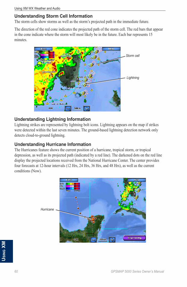
�0 GPSMAP 5000 Series Owner’s Manual
Using XM WX Weather and AudioU
Sin
G X
m
Understanding Storm Cell InformationThe storm cells show storms as well as the storm’s projected path in the immediate future.
The direction of the red cone indicates the projected path of the storm cell. The red bars that appear in the cone indicate where the storm will most likely be in the future. Each bar represents 15 minutes.
Storm cell
Lightning
Understanding Lightning InformationLightning strikes are represented by lightning bolt icons. Lightning appears on the map if strikes were detected within the last seven minutes. The ground-based lightning detection network only detects cloud-to-ground lightning.
Understanding Hurricane InformationThe Hurricanes feature shows the current position of a hurricane, tropical storm, or tropical depression, as well as its projected path (indicated by a red line). The darkened dots on the red line display the projected locations received from the National Hurricane Center. The center provides four forecasts at 12-hour intervals (12 Hrs, 24 Hrs, 36 Hrs, and 48 Hrs), as well as the current conditions (Now).
Hurricane

GPSMAP 5000 Series Owner’s Manual ��
Using XM WX Weather and AudioU
SinG Xm
Understanding Marine WarningsWhen a Marine Warning is issued, the area for the warning is highlighted in red. To view information about the warning, touch the warning area. The light blue lines on the chart indicate marine weather warning zones.
Marine Warning
Understanding County WarningsWhen the National Weather Service issues a weather warning for a county, the county is highlighted with the color corresponding to the warning. To view information about the warning, touch the county.
Tornado Warning
Severe Thunderstorm Warning
Flood Warning
Flash Flood Warning
Viewing Forecast InformationForecasts show the weather conditions including fronts and precipitation.
From the Home screen, touch Weather > Forecast.
To view the forecast for another time period:1. From the Home screen, touch Weather > Forecast.2. Touch Next Forecast. The forecasted weather for the next 12 hours is shown.3. Touch Next Forecast again to view forecasts for the next 24, 36, and 48 hours.
To view forecast information for another location:Touch and drag the screen until the screen displays the location you want.
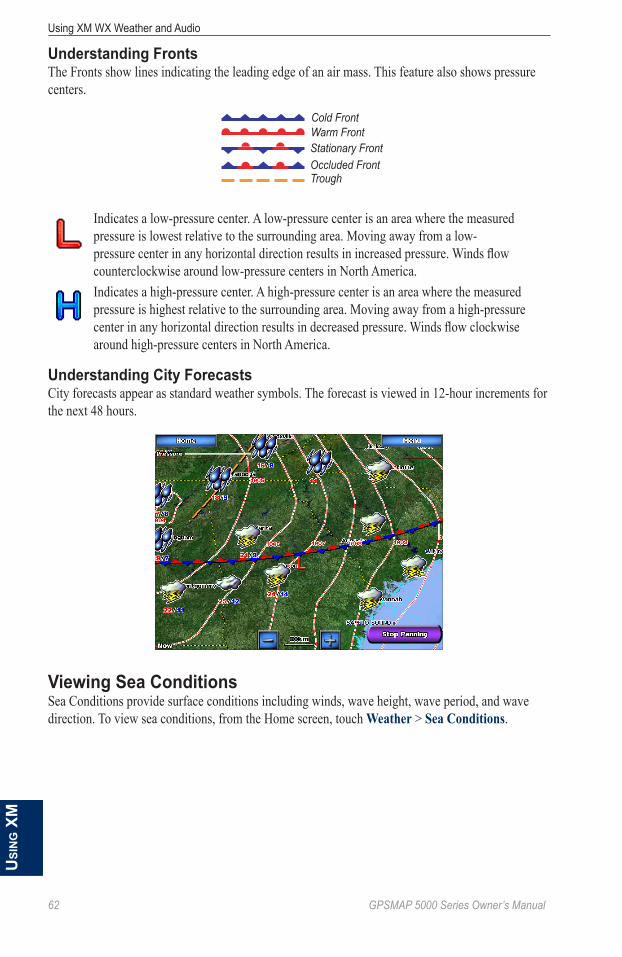
�2 GPSMAP 5000 Series Owner’s Manual
Using XM WX Weather and AudioU
Sin
G X
m
Understanding FrontsThe Fronts show lines indicating the leading edge of an air mass. This feature also shows pressure centers.
Cold FrontWarm FrontStationary FrontOccluded FrontTrough
Indicates a low-pressure center. A low-pressure center is an area where the measured pressure is lowest relative to the surrounding area. Moving away from a low-pressure center in any horizontal direction results in increased pressure. Winds flow counterclockwise around low-pressure centers in North America.Indicates a high-pressure center. A high-pressure center is an area where the measured pressure is highest relative to the surrounding area. Moving away from a high-pressure center in any horizontal direction results in decreased pressure. Winds flow clockwise around high-pressure centers in North America.
Understanding City ForecastsCity forecasts appear as standard weather symbols. The forecast is viewed in 12-hour increments for the next 48 hours.
Viewing Sea ConditionsSea Conditions provide surface conditions including winds, wave height, wave period, and wave direction. To view sea conditions, from the Home screen, touch Weather > Sea Conditions.
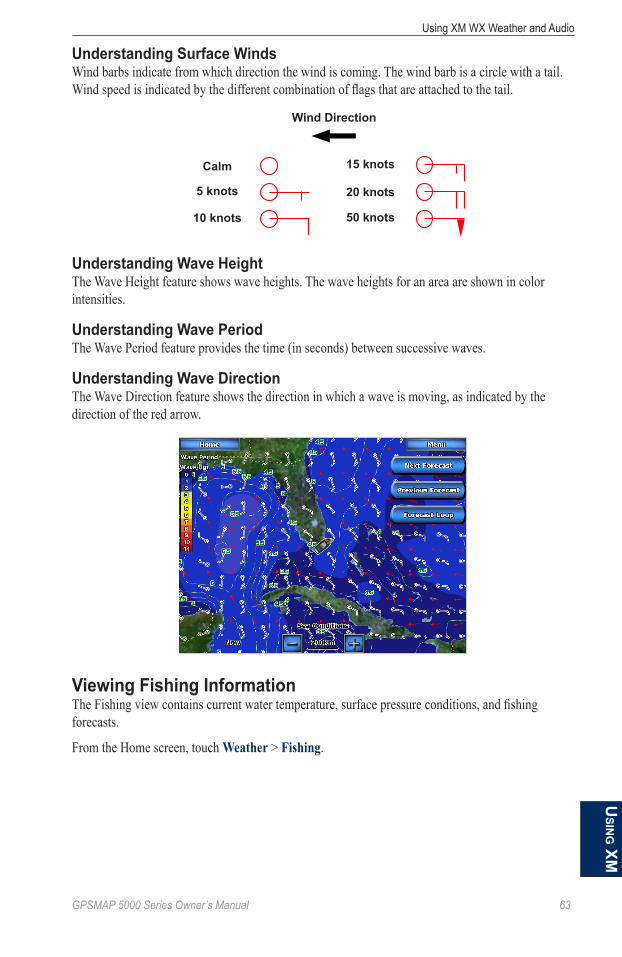
GPSMAP 5000 Series Owner’s Manual �3
Using XM WX Weather and AudioU
SinG Xm
Understanding Surface WindsWind barbs indicate from which direction the wind is coming. The wind barb is a circle with a tail. Wind speed is indicated by the different combination of flags that are attached to the tail.
Calm
5 knots
10 knots
15 knots
20 knots
50 knots
Wind Direction
Understanding Wave HeightThe Wave Height feature shows wave heights. The wave heights for an area are shown in color intensities.
Understanding Wave PeriodThe Wave Period feature provides the time (in seconds) between successive waves.
Understanding Wave DirectionThe Wave Direction feature shows the direction in which a wave is moving, as indicated by the direction of the red arrow.
Viewing Fishing InformationThe Fishing view contains current water temperature, surface pressure conditions, and fishing forecasts.
From the Home screen, touch Weather > Fishing.

�� GPSMAP 5000 Series Owner’s Manual
Using XM WX Weather and AudioU
Sin
G X
m
Understanding Surface PressureThis feature shows pressure isobars and pressure centers. The isobars connect points of equal pressure. Pressure readings can help determine weather and wind conditions in an area. High pressure areas are generally associated with fair weather. Low pressure areas are generally associated with clouds and the chance of precipitation. Isobars packed closely together show a strong pressure gradient. Strong pressure gradients are associated with areas of stronger winds.
Pressure units are shown in Millibars (mb), Inches of Mercury (in), and Hectopascals (hPa).
Understanding Water Temperature DataThe Water Temperature feature indicates the water’s surface temperature, as indicated by the legend on the left of the screen. The temperature breaks are indicated by isotherm lines.
Viewing Fish ForecastingThis feature shows areas that contain optimal weather conditions for specific species of fish.1. From the Home screen touch Weather > Fishing > Menu > Fish Species.2. Touch a species of fish. Shaded areas indicate optimal fishing areas.
Viewing Visibility InformationVisibility is the forecast maximum horizontal distance that can be seen at the surface, as indicated by the legend on the left of the screen. Contour lines on the Visibility feature show the forecasted change in surface visibility.
From the Home screen touch Weather > Visibility.
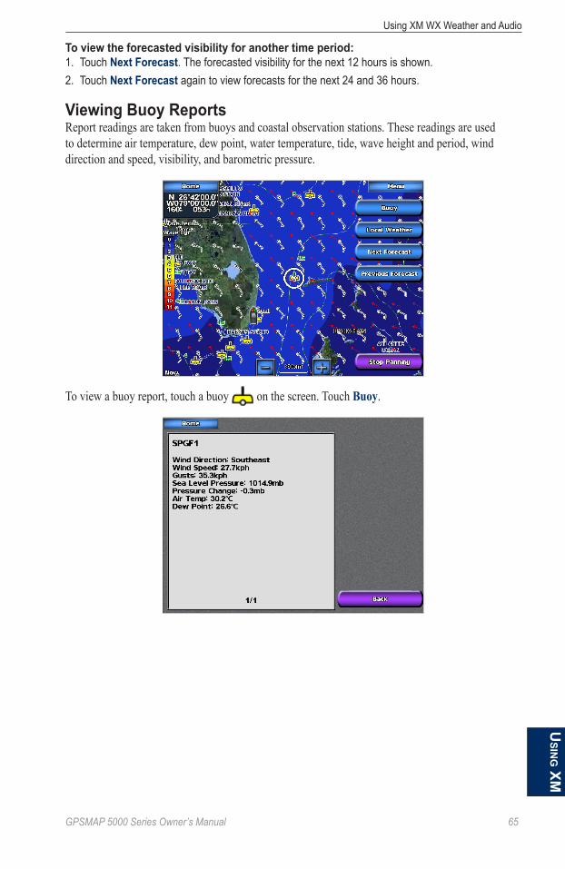
GPSMAP 5000 Series Owner’s Manual �5
Using XM WX Weather and AudioU
SinG Xm
To view the forecasted visibility for another time period:1. Touch Next Forecast. The forecasted visibility for the next 12 hours is shown. 2. Touch Next Forecast again to view forecasts for the next 24 and 36 hours.
Viewing Buoy ReportsReport readings are taken from buoys and coastal observation stations. These readings are used to determine air temperature, dew point, water temperature, tide, wave height and period, wind direction and speed, visibility, and barometric pressure.
To view a buoy report, touch a buoy on the screen. Touch Buoy.

�� GPSMAP 5000 Series Owner’s Manual
Using XM WX Weather and AudioU
Sin
G X
m
Using XM AudioWhen a Garmin XM Audio receiver and antenna is connected to the Garmin Marine Network and to the audio input of your boat, you can listen to XM Audio channels.
To display the XM Audio interface while navigating: From the Navigation screen, touch Menu > Data Bars > XM Audio > On.
Channel select
Channel display
To select an XM Audio Channel: Touch the right or left channel select arrows to change to the next channel in the current
category.
To use the XM Audio Guide: Touch the channel display bar.Channel Guide—selects the specific XM channel within the currently selected category.
Channel entry—allows you to enter a channel using the screen keyboard.
Save Preset—saves the current XM channel in the Presets list. Press Delete Preset to remove the current channel from the list. Presets is displayed as a category in the category list.
Category—selects the category of channels that are displayed in the Channel Guide.
Mute—silences the audio.

GPSMAP 5000 Series Owner’s Manual ��
Appendix
AppendixSpecificationsPhysical SpecificationsSize: GPSMAP 5208: 6⅞ in. H × 10⅛ in. W × 4⅛ in. D (173.5 × 256 × 105.9 mm) GPSMAP 5212: 9½ in. H × 13 in. W × 4¾ in. D (240.5 × 330 × 119.2 mm) GPSMAP 5215: 11⅝ in. H × 15½ in. W × 5⅝ in. D (295.8 × 394.9 × 143.8 mm) Weight: GPSMAP 5208: 5 lb., 15 oz. (2.7 kg) GPSMAP 5212: 9 lb., 8 oz. (4.3 kg) GPSMAP 5215: 12 lb., 14 oz. (5.4 kg) Display: GPSMAP 5208: 5 in. H × 6¾ in. W (128.2 × 170.9 mm) GPSMAP 5212: 7⅛ in. H × 9¼ in. W (180.5 × 236 mm) GPSMAP 5215: 9 in. H × 12 in. W (228.1 × 304.1 mm) Case: Fully Gasketed, high-impact plastic and aluminum alloy, waterproof to IEC 529-IPX-7 temp. Range: from 5°F to 131°F (from -15°C to 55°C) Compass Safe Distance: GPSMAP 5208: 31½ in. (80 cm) GPSMAP 5212: 39½ in. (1 m) GPSMAP 5215: 15¾ in. (40 cm)Hg - LaMPS iNSiDe tHiS PRoDUCt CoNtaiN MeRCURy aND MUSt Be ReCyCLeD oR
DiSPoSeD oF aCCoRDiNG to LoCaL, State, oR FeDeRaL LaWS.
For more information go to: www.garmin.com/aboutGarmin/environment/disposal.jsp.
GPS PerformanceReceiver: Differential-ready 12 parallel channel WAAS-capable receiver acquisition times: Warm: 15 seconds Cold: 45 seconds autoLocate®: 2 minutes Update Rate: 1/second, continuous GPS accuracy: Position: <15 m (49 ft.), 95% typical Velocity: 0.05 meters/second steady state WaaS accuracy: Position: <3 m (9.8 ft.), 95% typical Velocity: 0.05 meters/second steady state Dynamics: 6gs
Power:Source: 10-35 VDC Usage: 5208: 35 W max. at 10 VDC 5212: 40 W max at 10 VDC 5215: 60 W max at 10 VDC Fuse: 7.5 A, 42 V fast-acting
NMEA 2000 Specifications:Load Equivalency Number (LEN): 2 Unit Draw: 75 mA max

�8 GPSMAP 5000 Series Owner’s Manual
Appendix
Calibrating the TouchscreenYour chartplotter’s touchscreen does not normally require calibration. However, if the buttons do not seem to be responding properly, use the following process to calibrate the screen.1. While the chartplotter is turned off, press the Power key.2. When the Warning screen appears (with the I Agree button), touch anywhere on the black
portion of the screen for approximately 15 seconds until the Calibration screen is displayed.
3. Follow the instructions on the screen until “Calibration is complete” is displayed.4. Touch OK.
Capturing Screenshots Note: To capture screenshots, you need the optional Garmin RF Wireless Remote Control.
You can capture a screenshot of any screen displayed on your chartplotter as a bitmap (.BMP) file and then transfer it to your computer.
To capture screenshots:1. Insert an SD card into the SD card slot on the front of the chartplotter. 2. Touch Configure > System > Beeper/Display.3. Touch Screenshot Capture to turn screenshot captures On.4. When you are on a screen you want to capture, press the HOME button on the Garmin RF
Wireless Remote Control for at least six seconds.5. Touch OK when the Screenshot Taken window is displayed.
To copy the screenshots to your computer:1. Remove the SD card from the chartplotter and insert it into an SD card reader that is attached to
a computer.2. From Windows Explorer, open the Garmin\scrn folder on the SD card.3. Copy the appropriate .BMP file on the card and paste it to any location on the computer.

GPSMAP 5000 Series Owner’s Manual ��
Appendix
NMEA 0183 and NMEA 2000A GPSMAP 5000 series chartplotter can accept data from both NMEA 0183 compliant devices and certain NMEA 2000 devices connected to an existing NMEA 2000 network on your boat.
NMEA 0183The NMEA 0183 data cable included with GPSMAP 5000 series chartplotters supports the NMEA 0183 standard, which is used to wire various NMEA 0183-compliant devices, such as VHF radios, NMEA instruments, autopilots, wind sensors, and heading sensors.
The GPSMAP 5000 series chartplotter can receive data from up to four NMEA 0183-compliant devices and send GPS data to up to six NMEA 0183-compliant devices.
To wire the GPSMAP 5000 series chartplotter to optional NMEA 0183-compliant devices, see the GPSMAP 4000/5000 Series Installation Instructions.
Approved NMEA 0183 SentencesGPBWC, GPRMC, GPGGA, GPGSA, GPGSV, GPGLL, GPBOD, GPRMB, GPRTE, GPVTG, GPWPL, GPXTE, and Garmin proprietary sentences PGRME, PGRMM, and PGRMZ.
This chartplotter also includes support for the WPL sentence, DSC, and sonar NMEA 0183 input with support for the DPT (depth) or DBT, MTW (water temp), and VHW (water temp, speed, and heading) sentences.
To enable or disable NMEA 0183 output sentences:1. From the Home screen, touch Configure > Communications > NMEA 0183 Setup > Output
Sentences.2. Select a setting (Sounder, Route, System, or Garmin).3. Select the NMEA 0183 output sentence.4. Touch Off to disable, or touch On to enable, the NMEA 0183 output sentence.
NMEA 2000GPSMAP 5000 series chartplotters are NMEA 2000 certified, and can receive data from a NMEA 2000 network installed on the boat to show specific information on the Information screen, such as depth, speed, water temperature, wind speed and direction, and engine data.
To connect a GPSMAP 5000 series chartplotter to an existing NMEA 2000 network and to see a list of supported NMEA 2000 PGN numbers, see the GPSMAP 4000/5000 Series Installation Instructions.
All GPSMAP 5000 series units are NMEA 2000 certified.
�0 GPSMAP 5000 Series Owner’s Manual
Appendix
Messages and AlarmsaiS: Dangerous target—an AIS target currently presents a collision threat.
alarm Clock—the alarm clock alarm has sounded.
anchor Drag alarm—boat has drifted out of the user-set distance range.
antenna input is Shorted —there is a short in the wiring to the GPS 17 antenna.
Approaching Waypoint <name>—boat is a specified alarm distance from the destination waypoint.
Arrival Alarm <name>—arriving at destination waypoint.
auto-guidance unable to calculate route—(BlueChart g2 Vision) auto-guidance cannot calculate the route.
auto-guidance unable to calculate route. ending position not within safe depth—(BlueChart g2 Vision) auto-guidance cannot calculate the route; choose an end point within the specified safe depth.
auto-guidance unable to calculate route. Starting position not within safe depth—(BlueChart g2 Vision) auto-guidance cannot calculate the route; travel to water within the specified safe depth.
auto-guidance unable to calculate route, please shorten route—(BlueChart g2 Vision) auto-guidance cannot calculate the route, choose closer end point.
Battery alarm—user-set battery alarm has sounded.
Boat is not Moving Fast enough to Calibrate—(speed sensor) appears during water speed calibration. Check speed wheel for blockage and calibrate again. If wheel is clear, calibrate again and increase speed.
Calibration is complete—touchscreen calibration successful.
Can’t Read User Card—cannot read card when attempting a user data transfer.
Can’t Read Voltages that High, Limited to top of Range—entering a battery alarm voltage higher than the chartplotter can read.
Can’t Read Voltages that Low, Limited to Bottom of Range—entering a battery alarm voltage lower than the chartplotter can read.
Can’t Unlock Maps—maps are locked and cannot be used on this chartplotter.
Can’t Write User Card—cannot write card when attempting a user data transfer.
Cartography Service incompatible. Software Update Required—a software update is needed. Contact product support for assistance updating your chartplotter software.
Check XM antenna—XM antenna not connected. Check connectivity.
Cooling Fan Voltage too High—the chartplotter’s cooling fan voltage is higher than expected. Contact product support.
Cooling Fan Voltage too Low—the chartplotter’s cooling fan voltage is lower than expected. Contact product support.
Database error—general database error. Contact product support.
Deep Water alarm—(sonar) boat has entered user-defined value for deep water.
Directory item With this MMSi already exists—MMSI number already in directory.

GPSMAP 5000 Series Owner’s Manual ��
Appendix
Directory Memory is Full Can’t Create entry—DSC directory is full, no more entries can be created.
Distress Call Received from <name>—distress call has been received by the DSC module.
Drift alarm—boat has moved a user-defined distance.
DSC Position Report Received From <name>—a position report has been received by the DSC module.
entering target Water temperature—(temperature sensor/transducer) the water temperature is inside the user-defined target temperature zone.
Flash Flood Warning alarm—(XM WX weather) there is a flash flood warning in effect.
Flood Warning alarm—(XM WX weather) there is a flood warning effective.
GPS accuracy alarm—the GPS accuracy has fallen outside the user-set value.
GPS antenna Has Lost its Stored Settings—The GPS antenna’s memory has been cleared. Contact product support.
GPS Service incompatible. Software Update Required—a GPS service software update is needed. Contact product support for assistance updating your chartplotter software.
GPS Service Lost—the chartplotter has lost communications with the remote GPS device. Check the network and the antenna wiring.
incompatible Device, Software Update Required—an incompatible device is attached that requires a software update. Contact product support for assistance updating your network.
invalid Date—an invalid date was entered.
invalid Device instance. enter a number between (0 - 252)—invalid NMEA 2000 Device instance.
invalid entry. Default value selected.—an invalid entry was entered.
invalid MMSi—an invalid DSC MMSI was entered.
invalid System instance. enter a number between (0 - 15)—invalid NMEA 2000 System instance.
Leaving target Water temperature—(temperature sensor/transducer) the water temperature is outside the user-defined target temperature zone.
Lost Heading Sensor Connection— (radar/NMEA) the chartplotter has lost communications with the heading sensor. Check wiring.
Lost Remote GPS Connection—lost connection to the remote GPS. Check the network and the antenna wiring.
Lost Satellite Reception—the chartplotter has lost satellite reception. Make sure you have a clear view of the sky.
Low Fuel alarm—(NMEA 2000) low fuel reported by the NMEA 2000 network.
Map Format is Not Supported—a map format on a preprogrammed SD card is not supported.
Marine Weather Warning—(XM WX weather) there is a weather warning in effect.
MaRPa: Dangerous target—(radar) a MARPA target has become dangerous.
MaRPa: target Lost—(radar) unable to track a marpa target any longer.

�2 GPSMAP 5000 Series Owner’s Manual
Appendix
MDB Waypoint Memory is Full, Can’t Create Waypoint—MDB waypoint memory is full. Erase existing MDB waypoints to make room.
NMea Depth is Below transducer—(sonar) the NMEA depth input is using the DBT sentence which does not include keel offset.
No DGPS Position—chartplotter lost differential GPS reception (WAAS). Make sure you have a clear view of the sky.
No Proximity Waypoints Found—no proximity waypoints found while attempting a user data transfer.
No Routes Found—no routes found while attempting a user data transfer.
No tracks Found—no tracks found while attempting a user data transfer.
No User Waypoints Found—no user waypoints found while attempting a user data transfer.
No XM Signal—(XM WX weather) no XM satellite signal detected. Make sure you have a clear view of the sky.
Not all Maps Fit, Some Maps Will Not Be Drawn—there are more maps present on the SD card than what the chartplotter can support. Some of the maps on the card will not be drawn or used to find map features.
off Course alarm—the boat has left the user-defined course.
Proximity alarm—the boat has come close to a user-defined proximity point.
Proximity alarm Memory is Full—the proximity waypoint memory is full. Erase existing proximity waypoints to make room.
Proximity overlaps another Proximity Waypoint—a proximity point is overlapping another proximity waypoint.
Radar Guard Zone alarm—(radar) an object has been detected in the user-defined radar guard zone.
Radar Needs Repair error Code—(radar) the radar needs repair. An error code will be listed to help diagnose the error.
Radar Service incompatible. Software Update Required—a radar software update is needed. Contact product support for assistance updating your network.
Radar Service Lost—(radar) the chartplotter has lost communications with the remote radar device. Check the network and the radar wiring.
Route already exists—the named route already exists. Choose another name.
Route is Full—the individual route is full, no more waypoints can be added.
Route Memory is Full, Can’t Create Route—the chartplotter’s route memory as a whole is full, no more routes can be created. Erase existing routes to make room.
Route truncated—some points on the end of the route have been discarded.
Severe Storm Warning—(XM WX weather) there is a severe storm warning in effect.
Shallow Water alarm—(sonar) the boat has entered the user-defined shallow water depth.
Simulating operation—the chartplotter is in simulator mode.
GPSMAP 5000 Series Owner’s Manual �3
Appendix
Sonar Failed, Unit Needs Repair—there has been a sonar failure and the unit needs to be sent in for repair. Contact product support.
Sonar Service incompatible. Software Update Required—a software update is needed. Contact product support for assistance updating your network.
Sonar Service Lost—(sonar) the chartplotter has lost communications with the remote sonar device. Check the network and the sonar wiring.
tide alarm—tide has reached user-specified tide alarm range.
tornado Warning alarm—(XM WX weather) a tornado warning is in effect.
track already exists—the named track already exists. Choose another name.
track Log Full—there is no longer any space in the active track log storage.
track Memory is Full, Can’t Create track—the saved track memory is full.
track truncated—some points on the end of the track have been discarded.
transducer Disconnected, Sonar turned off—the transducer has been disconnected. Sonar has been turned off. Check transducer wiring.
transfer Complete—user data transfer is complete.
Unknown bridge height within calculated auto-guidance route—(BlueChart g2 Vision) there is an unknown bridge height within auto-guidance route.
User Card Not Found—user data card transfer. Make sure an SD card is fully inserted.
Warning: auto-guidance route starting position moved due to safe depth settings—(BlueChart g2 Vision) auto-guidance has calculated the route, but the starting point has been moved to deeper water.
Warning: auto-guidance route ending position moved due to safe depth settings—(BlueChart g2 Vision) auto-guidance has calculated the route, but the end point has been moved to deeper water.
Water Speed Sensor is not Working—the water speed sensor is not working properly. Check the wheel for obstructions and check wiring.
Water temperature alarm—(temperature sensor/transducer) the water temperature has entered or left the user-defined water temperature alarm zone.
Waypoint already exists—the named waypoint already exists. Choose another name.
Waypoint Memory is Full, Can’t Create Waypoint—the User Waypoint memory is full. Erase existing waypoints to make room.
Weather Service incompatible. Software Update Required—an XM WX weather software update is needed. Contact product support for assistance updating your network.
Weather Service Lost—(XM WX weather) the weather service is no longer communicating. Make sure you have a strong XM signal. Check the network and the XM wiring.
XM Service incompatible. Software Update Required—an XM service software update is needed. Contact product support for assistance updating your network.

74 GPSMAP5000SeriesOwner’sManual
Appendix
Product RegistrationHelp us better support you by completing our online registration today. Go to http://my.garmin.com. Keep the original sales receipt, or a photocopy, in a safe place.
Contact GarminContact Garmin Product Support if you have any questions while using your chartplotter. In the USA, go to www.garmin.com/support, or contact Garmin USA by phone at (913) 397.8200 or (800) 800.1020.
In the UK, contact Garmin (Europe) Ltd. by phone at 0808 2380000.
In Europe, go to www.garmin.com/support and click Contact Support for in-country support information, or contact Garmin (Europe) Ltd. by phone at +44 (0) 870.8501241.
Declaration of Conformity (DoC)Hereby, Garmin, declares that this chartplotter is in compliance with the essential requirements and other relevant provisions of Directive 1999/5/EC.
To view the full Declaration of Conformity, see the Garmin Web site for your Garmin product: www.garmin.com.
Weather Data WarrantyTHE WEATHER DATA SOFTWARE PRODUCT IS PROVIDED “AS IS.” ALL OTHER WARRANTIES, EXPRESSED OR IMPLIED, INCLUDING ANY WARRANTY OF MERCHANTABILITY OR FITNESS FOR A PARTICULAR PURPOSE OR OF NON-INFRINGEMENT ARE HEREBY EXCLUDED.
USER SAFETYIf you use XM Services it is your responsibility to exercise prudent discretion and observe all safety measures required by law and your own common sense. You assume the entire risk related to your use of the Services. XM and Garmin assume no responsibility for accidents resulting from or associated with use of the Services. Your Radio Service includes traffic and weather information, and you acknowledge that such information is not for “safety for life”, but is merely supplemental and advisory in nature, and therefore cannot be relied upon as safety-critical in connection with any aircraft, sea craft or automobile usage. This information is provided “as is” and XM and Garmin disclaim any and all warranties, express and implied, with respect thereto or the transmission or reception thereof. XM and Garmin further do not warrant the accuracy, reliability, completeness or timeliness of the traffic and weather information disclosed on the Radio Service. In no event will XM and Garmin, their data suppliers, service providers, marketing/distribution, software or Internet partners or hardware manufacturers be liable to you or to any third party for any direct, indirect, incidental, consequential, special, exemplary or punitive damages or lost profits resulting from use of or interruptions in the transmission or reception of the Services. LIMITS ON OUR RESPONSIBILITYa) DISCLAIMERS.EXCEPT AS EXPRESSLY PROVIDED HEREIN, WE MAKE NO WARRANTY OR REPRESENTATION, EITHER EXPRESS OR IMPLIED, REGARDING THE RADIO SERVICE. YOUR USE OF THE SERVICE IS AT YOUR SOLE RISK. THE CONTENT AND FUNCTIONALITY OF THE SERVICE IS PROVIDED “AS IS” WITHOUT ANY WARRANTY OF ANY KIND, EXPRESS OR IMPLIED. ALL SUCH WARRANTIES OR REPRESENTATIONS (INCLUDING, WITHOUT LIMITATION, THE IMPLIED WARRANTIES OF MERCHANTABILITY, FITNESS FOR A PARTICULAR PURPOSE, TITLE AND NON-INFRINGEMENT) ARE HEREBY DISCLAIMED.b) LIMITATIONS OF LIABILITY.WE ARE NOT RESPONSIBLE FOR ANY SPECIAL, INCIDENTAL, OR CONSEQUENTIAL DAMAGES OR LOSSES RELATING TO THE USE OF THE RADIO SERVICE, WHETHER BASED ON NEGLIGENCE OR OTHERWISE. OUR TOTAL LIABILITY TO YOU AND ANY OTHER PERSONS RECEIVING OUR SERVICES, REGARDLESS OF THE CAUSE, WILL IN NO EVENT EXCEED THE AMOUNTS THAT YOU HAVE PAID TO US FOR THE SERVICE THAT YOU RECEIVED DURING THE SIX (6) MONTH PERIOD IMMEDIATELY PRIOR TO THE SPECIFIC EVENT THAT GAVE RISE TO THE APPLICABLE DAMAGE OR LOSS. THIS ALLOCATION OF RISK IS

GPSMAP5000SeriesOwner’sManual 75
Appendix
REFLECTED IN OUR PRICES. YOU MAY HAVE GREATER RIGHTS THAN DESCRIBED ABOVE UNDER YOUR STATE’S LAWS.This product was developed using DAFIF™, a product of the National Geospatial-Intelligence Agency.This product has not been endorsed or otherwise approved by the National Geospatial-Intelligence Agency, or the United States Department of Defense (10 U.S.C. 425).a. Under 10 U.S.C. 456, no civil action may be brought against the United States on the basis of the content of a navigational aid prepared or disseminated by either the former Defense Mapping Agency (DMA), National Imagery and Mapping Agency (NIMA), or the National Geospatial-Intelligence Agency (NGA).b. The DAFIF™ product is provided “as is,” and no warranty, express or implied, including, but not limited to the implied warranties of merchantability and fitness for particular purpose or arising by statute or otherwise in law or from a course of dealing or usage in trade, is made by NGA as to the accuracy and functioning of the product.c. Neither NGA nor its personnel will be liable for any claims, losses, or damages arising from or connected with the use of this product. The user agrees to hold harmless the United States National Geospatial-Intelligence Agency. The user’s sole and exclusive remedy is to stop using the DAFIF product. This product was developed using DAFIF, a product of the National Geospatial-Intelligence Agency.
Software License AgreementBY USING THE CHARTPLOTTER, YOU AGREE TO BE BOUND BY THE TERMS AND CONDITIONS OF THE FOLLOWING SOFTWARE LICENSE AGREEMENT. PLEASE READ THIS AGREEMENT CAREFULLY.Garmin grants you a limited license to use the software embedded in this device (the “Software”) in binary executable form in the normal operation of the product. Title, ownership rights, and intellectual property rights in and to the Software remain in Garmin.You acknowledge that the Software is the property of Garmin and is protected under the United States of America copyright laws and international copyright treaties. You further acknowledge that the structure, organization, and code of the Software are valuable trade secrets of Garmin and that the Software in source code form remains a valuable trade secret of Garmin. You agree not to decompile, disassemble, modify, reverse assemble, reverse engineer, or reduce to human readable form the Software or any part thereof or create any derivative works based on the Software. You agree not to export or re-export the Software to any country in violation of the export control laws of the United States of America
XM Satellite Radio Service AgreementXM Satellite Radio Inc.Hardware and required monthly subscription sold separately. Subscription fee is consumer only. Other fees and taxes, including a one-time activation fee may apply. All programming fees and weather data subject to change. XM WX weather data displays and individual product availability vary by hardware equipment. Reception of the XM signal may vary depending on location. Subscriptions subject to Customer Agreement included with the XM Welcome Kit and available at xmradio.com. Available only in the 48 contiguous United States. XM WX is a trademark of XM Satellite Radio Inc.
�� GPSMAP 5000 Series Owner’s Manual
Index
IndexAA-scope 53add turn 27aerial photos 15, 19AIS 41alarms
anchor drag 39arrival 39battery 39deep water 39fish 39messages 70safe zone 50setting 39shallow water 39sonar 39system 39water temp 39
anchor drag alarm 39appearance 18auto mag var 37automatic guidance 15, 20, 28, 40
Bbacking up data 33backlight
adjusting 3sensor 1
beeper options 36BlueChart 15bridging 38buoy 6
reports 65
Ccalibrate water speed 40category (XM) 42, 66celestial information 31change combination 22channel entry (XM) 42, 66channel guide (XM) 42, 66chart
fishing 6chart appearance 11charts
appearance 11borders 12detail 11fish eye 3D 6, 15fishing 15mariner’s eye 6, 15navigation 6settings 11using 6
clear user data 34coastal observation stations 65
cold front 62color mode
adjusting 3colors 17
sonar 53combinations 21communications settings 38configure 36course up 11cruising screen (radar) 46current stations 30
Ddata
clear user data 34transfer 32
data bars 11, 13, 18default settings 2depth 37, 53detail 11device list 38DSC 41, 55
EEBL 49elevation unit settings 37event log 36
Ffactory settings 2, 4fishing 63fish symbols 53flash flood warning 61flood warning 61forecasts (weather) 61front panel 1fronts (weather) 62fuel gauges 34
Ggain
sonar 54gauges 34
fuel 34go to 23GPS 36
performance 67grid north 37guide to 23
Hhazard colors 17heading 37Heading Line 12heading line 12
cruising screen 50Head Up 11high pressure center 62home screen 5hurricanes 60
IID number 4initializing the unit 67initial settings 2inset map 12isobars 64
Lland only 18lane width 13lightning 60lightning bolt icons 60light sectors 12look-ahd spd 50low-pressure center 62
MMan Overboard 25map datum 38MapSource data 32marine network 43Mariner’s Eye
3D 16mariner’s eye 6mariner’s eye 3D
colors 17MARPA 48measure
units 37measure distance 10messages 70MOB 25moon phase 31moon rise/set 31my boat 40
NNational Weather Service 61Navaid Type 12navigation 23
stop 24navigation chart 6nearby stations 30network 43New Waypoint 13NMEA 69
0183 692000 69
NMEA 0183 38NMEA 2000 38north up 11numbers
viewing 30
Ooccluded front 62orientation 50other boats 34, 41overlay numbers 53

GPSMAP 5000 Series Owner’s Manual ��
Index
Ppanning 9photos 11, 18POI data 19position 37precipitation information 59preferred devices 38pressure
center 62gradient 64isobars 64unit settings 37
product registration 74projected path 60
Rradar 45
cross talk 49fast time constant 49overlay screen 48surface 13
range rings 13rear panel 1reset 4review 26rings 11, 50Roses 11routes
cancel 27creating 27deleting 29editing 29
route to 23
Ssafe
depth 13, 40height 37
satelliteimagery 18signals 3
save preset (XM) 42, 66scroll speed 53SD cards
inserting and removing 3using 16
search for destination 24Service Points 11settings
chart 11communications 38
severe thunderstorm warning 61simulator mode 4, 36software version 4
sonar 51A-scope 53advanced settings 53depth line 53gain 54range 53scroll speed 53setting up 53
sonar cone 17sonar data 18specifications 67speed unit settings 37split frequency
radar 52split zoom
radar 51spot depths 12stationary front 62storm cells 59sunrise/sunset 31surface noise 53surface radar 13surface winds 62symbols 8, 12system information 4
Ttargeting (radar) 47, 48temperature 37temp log 52tides/currents 11tide station 30tide stations 10time 38time zone 38tornado warning 61tracks 14, 18
editing/deleting 18transfer data 32transmit radar 45tropical depression 60tropical storm 60trough 62true north 37
Uunits of measure
changing 37user data
clearing 32transferring 33viewing 32
user mag var 37
Vvideo
viewing 35viewing
currents 30user data 32
visibility 64Vision
BlueChart g2 15volume unit settings 37VRM/EBL
adjusting 49
Wwarm front 62warnings
county 61marine 61
warranty 74water
speed (calibrate) 40temperature 64
wavedirection 62height 63period 62
waypoints 13creating 10, 25deleting 25, 26edit existing 13editing 26list of 26viewing 32
waypoints & tracks 6weather
data 59fronts 62
Where To 23whiteline 53wind
barb 63surface 62
wireless devices 38
XXM audio 42, 59, 66XM weather 59
Zzoom 6, 12, 17, 19, 54


For the latest free software updates (excluding map data) throughout the life of your Garmin products, visit the Garmin Web site at www.garmin.com.
© 2009 Garmin Ltd. or its subsidiaries
Garmin International, Inc. 1200 East 151st Street, Olathe, Kansas 66062, USA
Garmin (Europe) Ltd. Liberty House, Hounsdown Business Park, Southampton, Hampshire, SO40 9LR UK
Garmin Corporation No. 68, Jangshu 2nd Road, Shijr, Taipei County, Taiwan
www.garmin.com
April 2009 Part Number 190-01079-00 Rev. A Printed in Taiwan