gpu acceleration of the fine/turbo cfd solver at the...
TRANSCRIPT
GPU Acceleration of the Fine/Turbo CFD Solver at the HPC Scale
David Gutzwiller, NUMECA USA
Alain Demeulenaere, NUMECA USA
Mathieu Gontier, NUMECA Int.
Ravi Srinivasan, Ramgen Power Systems
Authors and Contributors
Outline
1. Background • Fine/Turbo Toolset
• Existing HPC Capabilities
2. GPU / Many-core Strategy
3. Acceleration of the CPUBooster module
4. User Experience • Ramgen Power Systems
• Massively Parallel Design Optimization
5. Conclusions

Background
Background
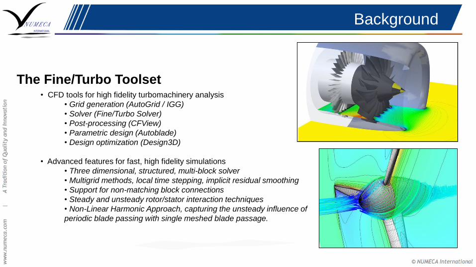
The Fine/Turbo Toolset • CFD tools for high fidelity turbomachinery analysis
• Grid generation (AutoGrid / IGG)
• Solver (Fine/Turbo Solver)
• Post-processing (CFView)
• Parametric design (Autoblade)
• Design optimization (Design3D)
• Advanced features for fast, high fidelity simulations
• Three dimensional, structured, multi-block solver
• Multigrid methods, local time stepping, implicit residual smoothing
• Support for non-matching block connections
• Steady and unsteady rotor/stator interaction techniques
• Non-Linear Harmonic Approach, capturing the unsteady influence of
periodic blade passing with single meshed blade passage.
Background
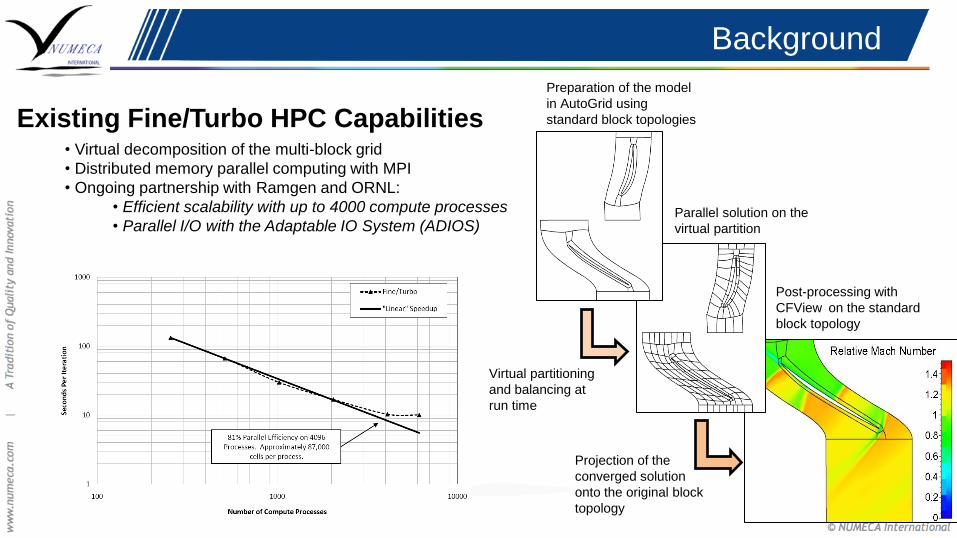
Existing Fine/Turbo HPC Capabilities • Virtual decomposition of the multi-block grid
• Distributed memory parallel computing with MPI
• Ongoing partnership with Ramgen and ORNL:
• Efficient scalability with up to 4000 compute processes
• Parallel I/O with the Adaptable IO System (ADIOS)
Preparation of the model
in AutoGrid using
standard block topologies
Parallel solution on the
virtual partition
Post-processing with
CFView on the standard
block topology
Virtual partitioning
and balancing at
run time
Projection of the
converged solution
onto the original block
topology

GPU / Many-Core
Strategy
GPU / Many-Core Strategy
General Solver Acceleration • Software Limitations
• The Fine/Turbo solver has roots in the early 1990s
• No clear separation of logic/program flow, algorithms, and data structures
• Data organized in monolithic integer and real vectors with complicated internal memory handling.
• Industrial Limitations
• Single code base for ease of maintenance
• Single solution for GPUs and alternative many-core hardware
• GPU / many-core enhancements should not interfere with ongoing solver developments
• Rewriting the entire solver for efficient acceleration would be very costly
• Adapting a computationally expensive module for GPU / many-core execution is a feasible alternative
Choosing an Attractive Module • Large amounts of arithmetic
• Preferably near the end of the call tree
• Minimal mixing of logic and arithmetic
Acceleration of the
CPUBooster Module

GPU Acceleration Results
Lower is better
1.4X global speedup
1.27X global speedup

CPUBooster Module
CPUBooster Convergence Acceleration Module • Advanced residual smoothing algorithm, bringing a level of implicitness to the time integration solver
• Permits the use of high CFL numbers, up to 1000
• Yields a drastic decrease in the number of iterations needed for convergence (~4x)
• Time per iteration is increased due to the additional module arithmetic (~2x)
• Attractive candidate for threaded execution, either on CPU or GPU
• Global iteration speedup from GPU acceleration will be bound to 2x
CPUBooster Module
CPUBooster : Additional Information • In a distributed parallel environment, the CPUBooster is called by each MPI rank on a block-by-block basis
• Due to the multigrid nature of Fine/Turbo, the CPUBooster is called several times per iteration
• At each call to the module a significant amount of data must be transferred, updated, or created
• Geometric quantities (10 per cell, copy in)
• Input primitives (16 per cell, copy in)
• Output residuals (7 per cell, copy in-out)
• Local quantities (31 per cell, local on GPU)
Hardware Considerations • The Titan nodes are equipped with PCIe 2.0
• Each node contains 16 CPU cores, all of which will simultaneously transfer data to a single GPU
• Bandwidth in/out of the GPU is a serious bottleneck
• GPU memory is also a limitation for larger computations
From the numbers above, it can be expected that data
transfer may further limit the possible acceleration
CPUBooster Module – GPU Porting
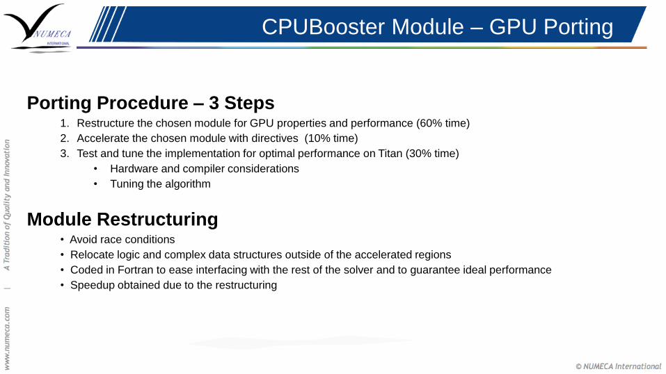
Porting Procedure – 3 Steps 1. Restructure the chosen module for GPU properties and performance (60% time)
2. Accelerate the chosen module with directives (10% time)
3. Test and tune the implementation for optimal performance on Titan (30% time)
• Hardware and compiler considerations
• Tuning the algorithm
Module Restructuring • Avoid race conditions
• Relocate logic and complex data structures outside of the accelerated regions
• Coded in Fortran to ease interfacing with the rest of the solver and to guarantee ideal performance
• Speedup obtained due to the restructuring
CPUBooster Module – GPU Porting
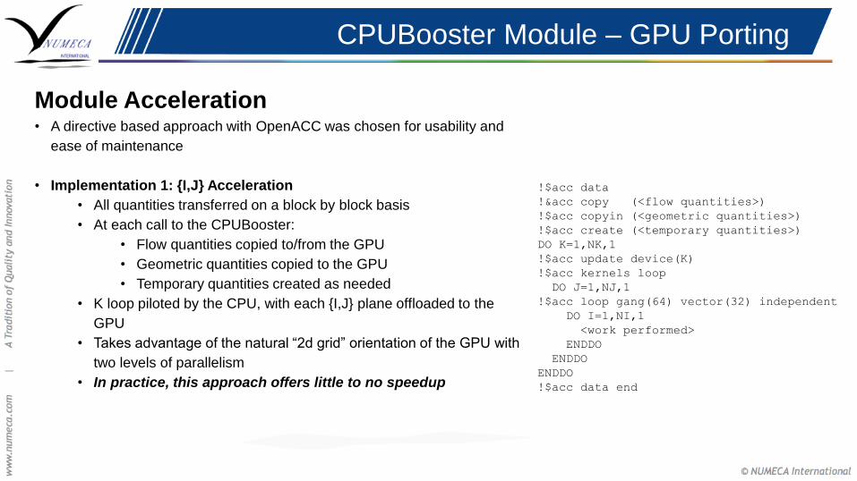
Module Acceleration • A directive based approach with OpenACC was chosen for usability and
ease of maintenance
• Implementation 1: {I,J} Acceleration
• All quantities transferred on a block by block basis
• At each call to the CPUBooster:
• Flow quantities copied to/from the GPU
• Geometric quantities copied to the GPU
• Temporary quantities created as needed
• K loop piloted by the CPU, with each {I,J} plane offloaded to the
GPU
• Takes advantage of the natural “2d grid” orientation of the GPU with
two levels of parallelism
• In practice, this approach offers little to no speedup
!$acc data
!&acc copy (<flow quantities>)
!$acc copyin (<geometric quantities>)
!$acc create (<temporary quantities>)
DO K=1,NK,1
!$acc update device(K)
!$acc kernels loop
DO J=1,NJ,1
!$acc loop gang(64) vector(32) independent
DO I=1,NI,1
<work performed>
ENDDO
ENDDO
ENDDO
!$acc data end
CPUBooster Module – GPU Porting
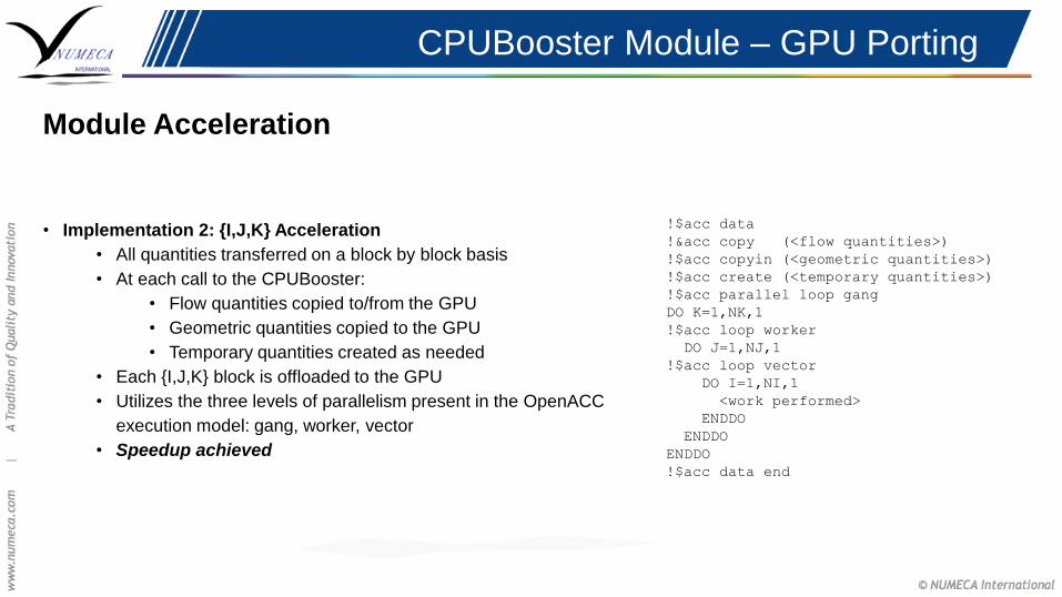
Module Acceleration
• Implementation 2: {I,J,K} Acceleration
• All quantities transferred on a block by block basis
• At each call to the CPUBooster:
• Flow quantities copied to/from the GPU
• Geometric quantities copied to the GPU
• Temporary quantities created as needed
• Each {I,J,K} block is offloaded to the GPU
• Utilizes the three levels of parallelism present in the OpenACC
execution model: gang, worker, vector
• Speedup achieved
!$acc data
!&acc copy (<flow quantities>)
!$acc copyin (<geometric quantities>)
!$acc create (<temporary quantities>)
!$acc parallel loop gang
DO K=1,NK,1
!$acc loop worker
DO J=1,NJ,1
!$acc loop vector
DO I=1,NI,1
<work performed>
ENDDO
ENDDO
ENDDO
!$acc data end
CPUBooster Module – GPU Porting
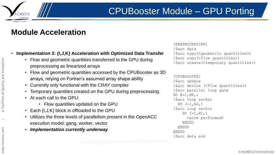
Module Acceleration
• Implementation 3: {I,J,K} Acceleration with Optimized Data Transfer
• Flow and geometric quantities transferred to the GPU during
preprocessing as linearized arrays
• Flow and geometric quantities accessed by the CPUBooster as 3D
arrays, relying on Fortran’s assumed array shape ability
• Currently only functional with the CRAY compiler
• Temporary quantities created on the GPU during preprocessing.
• At each call to the GPU:
• Flow quantities updated on the GPU
• Each {I,J,K} block is offloaded to the GPU
• Utilizes the three levels of parallelism present in the OpenACC
execution model: gang, worker, vector
• Implementation currently underway
[PREPROCESSING]
!$acc data
!$acc copy(<geometric quantities>)
!$acc copy(<flow quantities>)
!$acc create(<temporary quantities>)
[CPUBOOSTER]
!$acc update
!&acc device (<flow quantities>)
!$acc parallel loop gang
DO K=1,NK,1
!$acc loop worker
DO J=1,NJ,1
!$acc loop vector
DO I=1,NI,1
<work performed>
ENDDO
ENDDO
ENDDO
!$acc data end
CPUBooster Module – GPU Porting
Testing and Tuning
• Block Filtering
• It may not be worthwhile to offload extremely small blocks to the GPU due to the latency and bandwidth
constraints of the PCIe 2.0 connection
• Small blocks may be “filtered”, either by skipping coarse grid levels or by block size
• Compiler Considerations
• Writing truly portable code with OpenACC is still difficult
• The mainstream compilers interpret certain OpenACC directives differently, sometimes yielding incomplete
acceleration
• Possibly due to a leak in the OpenACC standard?
• Possibly due to rapidly maturing compiler support?
• The CRAY compiler has been shown to be the most effective for accelerating the CPUBooster on Titan
GPU Acceleration Results
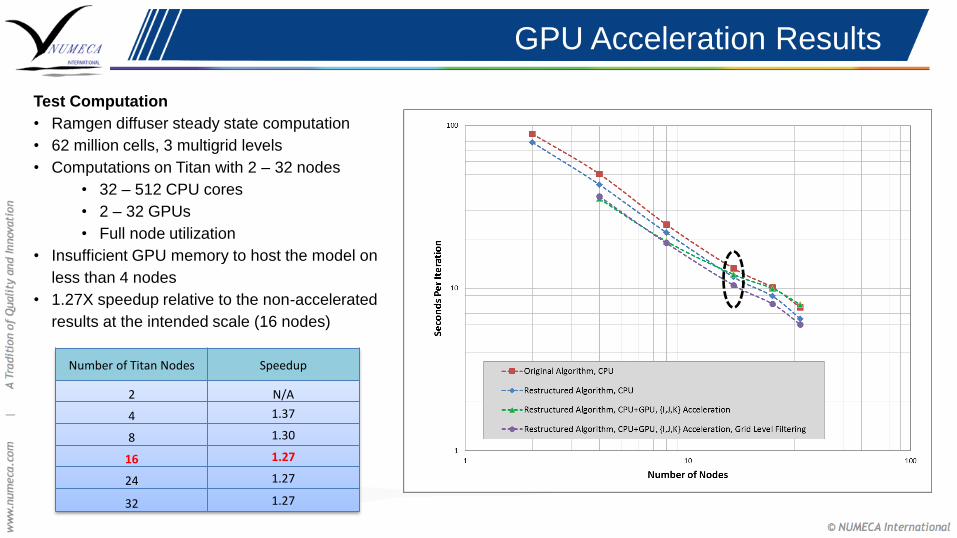
Test Computation
• Ramgen diffuser steady state computation
• 62 million cells, 3 multigrid levels
• Computations on Titan with 2 – 32 nodes
• 32 – 512 CPU cores
• 2 – 32 GPUs
• Full node utilization
• Insufficient GPU memory to host the model on
less than 4 nodes
• 1.27X speedup relative to the non-accelerated
results at the intended scale (16 nodes)
Number of Titan Nodes Speedup
2 N/A
4 1.37
8 1.30
16 1.27
24 1.27
32 1.27
User Experience
Ramgen Power Systems
User Experience : Ramgen Power Systems
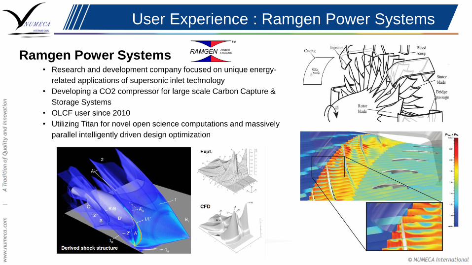
Ramgen Power Systems • Research and development company focused on unique energy-
related applications of supersonic inlet technology
• Developing a CO2 compressor for large scale Carbon Capture &
Storage Systems
• OLCF user since 2010
• Utilizing Titan for novel open science computations and massively
parallel intelligently driven design optimization

User Experience : Ramgen Power Systems
Intelligently Guided Design Optimization

User Experience : Ramgen Power Systems
Representative Example – Diffuser Optimization • Baseline sample:
• Single passage mesh, 62 million cells
• 3500 iterations required for convergence
• Time to solution on 16 Titan nodes : 6.5 hours
• Previous optimization database work:
• 3000 samples, completed in 2012
• Computed in 4 batches, 750 samples each utilizing 12,000 titan nodes
• Total computational cost: 312,000 node-hours
• Recent performance improvements:
• 4X decrease in number of iterations to convergence
• 2X increase in CPU time per iteration
• 1.27X decrease in global compute time due to offloading arithmetic to the GPU
• Total computational cost: 123,000 node-hours
2.54X improvement in turnaround time and system resource usage
Summary & Conclusions
• The GPU acceleration of the Fine/Turbo CFD solver has been presented
• The CPUBooster convergence acceleration module has been identified as an attractive candidate
for GPU and Many-Core acceleration
• Restructuring and instrumentation of the CPUBooster module with OpenACC directives has
yielded a global iteration speedup of 1.2X-1.4X
• With proper code restructuring, OpenACC allows easy GPU acceleration
• The OpenACC standard needs to mature before truly portable code is possible
• The use of the CPUBooster module along with the Titan GPUs results in a 2.54X decrease in
turnaround time and resource usage for Ramgen’s massively parallel design optimization work.
• Potential future work:
• Improved data locality and minimized transfer
• Asynchronous execution with block filtering
• Acceleration of additional solver modules
Acknowledgements
This research used resources of the Oak Ridge Leadership Computing Facility at the
Oak Ridge National Laboratory, which is supported by the Office of Science of the U.S.
Department of Energy under Contract No. DEAC05-00OR22725.
Special Thanks To:
John Levesque (CRAY)
Jeff Larkin (Nvidia)
For their constant support and advice during the GPU porting process

Thank You
Questions?