gr 2400 installation guide - acuity brands · gr 2400 installation guide step 1. ed in the...
TRANSCRIPT

GR 2400INSTALLATION GUIDEStep 1.
ed in the scinortcele dna syaler eht peek oT .stnemucod noitcurtsnoc
clean during rough-in, you can remove the panel interior.
Mounting Hole Dimensions . . . . . . . . . . . . . . . . . . . . . . . . .2Removing the Panel Interior . . . . . . . . . . . . . . . . . . . . . . . .3
Step 2.Make up conduit and gutters to breaker panels.
Knockouts (KO) . . . . . . . . . . . . . . . . . . . . . . . . . . . . . . . . . . . . .3Panel Wiring . . . . . . . . . . . . . . . . . . . . . . . . . . . . . . . . . . . . . . . .4
Step 3.Prior to pulling cables from the breaker panels, review the customer-approved panel schedule on the door of the panel. For systems not factory pre-programmed, create a panel schedule.
Controlling Emergency Power . . . . . . . . . . . . . . . . . . . . . .4Mixed Voltages/Mixed Source . . . . . . . . . . . . . . . . . . . . . . .4How to Read a Panel Schedule . . . . . . . . . . . . . . . . . . . . . .8How to Create a New Panel Schedule . . . . . . . . . . . . . . . .9
Step 4.Land conductors per the panel schedule. Use the Fault Check Procedure to detect and prevent faults from damaging relays during start-up.
Fault Check Procedure . . . . . . . . . . . . . . . . . . . . . . . . . . . . . .5 Torque Specs and Instructions . . . . . . . . . . . . . . . . . . . . . .5
System Installer Read This First
Read this Installation Guide before starting and reduce your installation time by 50%. Call us if you have questions or need assistance during the installation. Technical Support: 800-345-4448
Step 5.Connect power supply to 120V or 277V (use appropriate lug) neutral and ground. Use a dedicated breaker.
Controlling Emergency Power . . . . . . . . . . . . . . . . . . . . . .4
Do not power-up the panel electronics until the bus has been activated (see the Quick-Start Guide and the Final Activation Checklist).
Step 6.Make up Cat. 5 cable per the Quick-Start Guide.
AppendixLine- & Low-Voltage Connections . . . . . . . . . . . . . . . . . . . .6Internal Wiring Schematic . . . . . . . . . . . . . . . . . . . . . . . . . . .7Creating Programmable Panel Schedules . . . . . . . . . . . .9GR 2400 Panel with Call-Outs . . . . . . . . . . . . . . . . . . . . . . .10Troubleshooting . . . . . . . . . . . . . . . . . . . . . . . . . . . . . . . . . . .11

Pg. 2 www.lightingcontrols.com
PANEL MOUNTING
Control Panel Enclosure
Top & Bottom End-caps: See detail for knockout positions
Mounting Hardware (not included)
0.3/8" holes for mounting
Recommended knockouts
for line-voltage runsRecommended knockouts
for low-voltage runsRecommended knockouts
for line-voltage runs
Removable Backplate: For ease of installationFastening Bolts: For inner panel
Mounting Hole DimensionsThe standard GR 2432 (32 relays) model is shown below.The GR 2448 (48 relays) model is similar. Refer to the actual panel to verify details as required.

LC&D 800.345.4448 Pg. 3
Removing the Panel InteriorIf the rough-in is going to create a lot of dust or metal shavings, it may prove best to remove the chassis prior to installation. To remove the chassis:
1. Remove the four mounting screws.
2. Grab the top and bottom of the back plate and gently lift out of the enclosure.
3. Recommended: re-mount the screws and washers in the threaded holes on the back of the enclosure.
4. Store the panel interior in the original shipping box.
Upon request, the factory will ship the enclosure separately from the back plate.
Mounting the Enclosure1. Enclosure must be mounted on something substantial
like plywood or a 2' x 4' stud.
2. Use (customer supplied) 1/4" lag bolts.
Knockouts1. Note that the center section of the panel is reserved for
low voltage. While all KOs on the end-cap may be used for line voltage conduit, if the center KOs are used, those line-voltage conductors will be bent on a sharp radius.
2. Panels can be ordered with no KOs.
3. The pattern shown on the right is true for both the 32- and the 48-relay panel enclosures. Note that the end-cap on the bottom is reversed from the end-cap on the top (see diagram at left for clarifi cation).
NOTE: In diagram at right, end-cap confi guration may diff er if your GR 2400 is a special order item. Refer to actual panel for verifi cation.
Mounting surface
End-Cap Detail (top & bottom)
Right-edge locking down from top
Left-edge locking up from bottom
Right-edge locking down from top
Left-edge locking up from bottom
Pg. 4 www.lightingcontrols.com
PANEL WIRING
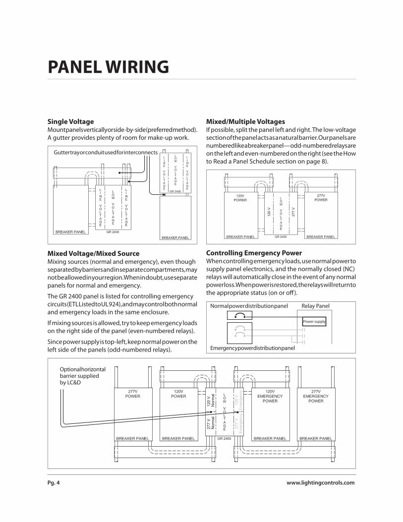
Single VoltageMount panels vertically or side-by-side (preferred method). A gutter provides plenty of room for make-up work.
Mixed Voltage/Mixed SourceMixing sources (normal and emergency), even though separated by barriers and in separate compartments, may not be allowed in your region. When in doubt, use separate panels for normal and emergency.
The GR 2400 panel is listed for controlling emergency circuits (ETL Listed to UL 924), and may control both normal and emergency loads in the same enclosure.
If mixing sources is allowed, try to keep emergency loads on the right side of the panel (even-numbered relays).
Since power supply is top-left, keep normal power on the left side of the panels (odd-numbered relays).
Gutter tray or conduit used for interconnects
Mixed/Multiple VoltagesIf possible, split the panel left and right. The low-voltage section of the panel acts as a natural barrier. Our panels are numbered like a breaker panel—odd-numbered relays are on the left and even-numbered on the right (see the How to Read a Panel Schedule section on page 8).
Controlling Emergency PowerWhen controlling emergency loads, use normal power to supply panel electronics, and the normally closed (NC) relays will automatically close in the event of any normal power loss. When power is restored, the relays will return to the appropriate status (on or off ).
120
VN
orm
al27
7 V
Nor
mal
120
VE
mer
genc
y27
7 V
Em
erge
ncy
Optional horizontal barrier suppliedby LC&D
277
V
120
V
Normal power distribution panel Relay Panel
Power supply
Emergency power distribution panel

LC&D 800.345.4448 Pg. 5
Fault Check Procedure:1. Land “line” and “load” conductors on the same terminal
lug. Label “line” conductor with breaker ID (see diagram).
2. Check the line. Switch breakers on and clear any faults. Switch breakers off .
3. Move the load conductors to the load terminal lug on each relay once tested.
Torque Specs and Instructions The torque spec for the relay terminal block is 16in-lbs. with a 1" diameter = ½" radius screwdriver, this means a turning force of 32 lbs.
Tighten and WiggleCopper is “ductile,” which means that it can compress and fl ow. To ensure a good connection in the terminal lug, follow this procedure.
1. Tighten the terminal to the specifi ed torque.
2. “Wiggle” the wire; Move it slowly from side-to-side while pulling gently.
3. Tighten again to the specifi ed torque. Usually this takes 1/16 to 1/4 of a turn or more.
4. Repeat as needed.
32 lbs
1" DiameterScrewdriver
1/2"

Pg. 6 www.lightingcontrols.com
PANEL WIRING (cont’d)
Line- & Low-Voltage Connections
!Danger: The dual-tap transformer in the diagram below (see arrow) generates an output voltage on the unused line voltage lug.
Example: If the 120V lug is used, the 277V lug will have a live voltage of 277V.

LC&D 800.345.4448 Pg. 7
Internal Wiring SchematicInternal jumpers and connector cables for the GR 2400 are shown and listed below. All internal wiring connections use depluggable connectors. Gently tug connectors after connection to ensure a fi rm fi t and visually inspect to seeif it’s seated properly.
Internal Connectors1. Three #18AWG: supplies power and neutral from input
card to transformer.
2. Four #18AWG: supplies power and reference ground from transformer to control card.
3. Up to 4 (GR 2432) / 6 (GR 2448) 14-conductor ribbon cables: carries control signal between control card & smacker strips.
4. Up to 32 (GR 2432) / 50 (GR 2448) 2-conductor ribbon cables: carries control signal from smacker strip to the relays. Two cables are used on the GR 2448 card (applies to the GR 2448 only).
5. One 8-conductor fl at cable: carries signal between control card & digital time clock (DTC).
6. Two terminators: provided inside sealed bag attached to DTC bracket for terminating bus.
7. One 20-conductor ribbon cable: connects GR 2448 card to control card (for GR 2448 only).
1
2
3
3
3
4 47
4
5 6
3
3
3

Pg. 8 www.lightingcontrols.com
PANEL SCHEDULES
How to Read a Panel ScheduleBe sure to follow your panel schedule exactly and you can reduce installation time by eliminating unnecessary re-documentation.
A. Note the odd-numbered relays on the left and even-numbered relays on the right column.
B. NC = Normally Closed Relay. Lighting Control & Design off ers a number of relay types. For more info go to lightingcontrols.com.
C. Cards can be in Discrete, 8-Zone or 16-Zone mode.
“Discrete Mode” means that every relay is separately controlled.
“Zone Mode” means the relays are controlled together, like a lighting contactor. When a panel is in “Zone Mode,” the
zones are controlled or scheduled, and the relays on the panel are manually assigned to the zone.
D. DP stands for “double-pole” relays.
E. Accessories: This panel has a DTC (master) and modem. All other remote panels linked to this will not have clocks.
F. Note the emergency loads (ensure this is allowed locally). The thick line on the panel schedule indicates a barrier (thin lines are used to count every four relays).
G. Panels use one address for every 8 zones/relays.
H. Panel summary generated by Unity.
Job Name:LCP Location:
Model #:LCP Name:
Supply Circuit: Voltage:
Comments:Joe's GarageElectrical Room 100GR 2432/26-DTC MODEM-HL-SMLCP 1HA-10 120V Normal
Relay Line Feed Zone Type Voltage Load Name Relay Line Feed Zone Type Voltage Load Name
R1 HA 1 NC 277V-N Hallway R2 LA 5 NC 120V-N Track CenterR3 HA 2 NC 277V-N Foyer R4 LA 6 NC 120V-N Track LeftR5 HA 3 NC 277V-N Sales Floor "a" R6 LA 7 NC 120V-N Track RightR7 HA 4 NC 277V-N Sales Floor "b" R8 LA 8 NC 120V-N Track FrontR9 HA 5 NC 277V-N Sales Flr Daylit R10 LA 9 NC 120V-N Track BackR11 HA 6 NC 277V-N Office 103 R12 LA 10 NC 120V-N Track EntryR13 HA 7 NC 277V-N Office 104 R14 LA 11 NC 120V-N ReceptsR15 HA 8 NC 277V-N Office 105 R16 LA 1 NC 120V-N RecerptsR17 HA 9 DP 480V-N Parking Lot R18 NC 120V-N SpareR19 HA 10 DP 480V-N Parking Lot R20 NC 120V-N SpareR21 HA 11 DP 480V-N Parking Lot R22 NC 120V-N SpareR23 HA 12 DP 480V-N Parking Lot R24 NC 120V-N SpareR25 HA 13 NC 277V-N Spare R26 /// 120V-N SPACE ONLYR27 NC 277V-E Spare R28 /// 120V-N SPACE ONLYR29 EHA 2 NC 277V-E Hall/Foyer Emer R30 /// 120V-N SPACE ONLYR31 EHA 4 NC 277V-E Sales Flr Emer R32 /// 120V-N SPACE ONLY
Enclosure:Dimensions:
Mounting:NEMA Rating:
Door Type:
Accessories: Relay Summary:Active Relays:Spare Relays:Total Relays:
Spaces:
Relay Types:Normally Closed:Two Poles (NC):
25.5"H x 20"W x 6"DSurface1Hinged, Locking
Digital Time ClockModem
206264
242
Programming Section OnlyCard Mode: Serial #:
Control Card Address:Discrete
1-4
A A
H
H
CG
B
D
F
E

LC&D 800.345.4448 Pg. 9
How to Create or Update Panel SchedulesLighting Control & Design off ers a simplifi ed version of the panel schedule (see page 8), which can be fi lled out by hand. The panel schedule is mounted on the door of all non-programmed panels.
Panel schedules are generated by Unity™ Lighting Control Software in just a few minutes.
Download Unity at lightingcontrols.com and update panel schedules changes as needed.
GR 2400 Relay Panel Schedule Job Name: ____________________________
LCP Location: __________________________
Modem #: _____________________________
Supply Circuit: ________ Voltage: _________
Comments:
Relay Line Feed Voltage Load Name
___-____ _____ ___________________-____ _____ ___________________-____ _____ ___________________-____ _____ ___________________-____ _____ ___________________-____ _____ ___________________-____ _____ ________________
____________________________________________________________________________________
Relay Line Feed Voltage Load Name
___-____ _____ ___________________-____ _____ ___________________-____ _____ ___________________-____ _____ ___________________-____ _____ ___________________-____ _____ ___________________-____ _____ ________________
Master PanelModem
Remote Panel
32 Relays48 Relays
Hardware specs
___-____ _____ ___________________-____ _____ ___________________-____ _____ ________________
___-____ _____ ___________________-____ _____ ___________________-____ _____ ________________
R1R3R5R7R9
R11R13R15R17R19R21
R2R4R6R8
R10R12R14R16R18R20R22
___-____ _____ ________________ ___-____ _____ ___________________-____ _____ ___________________-____ _____ ___________________-____ _____ ___________________-____ _____ ___________________-____ _____ ___________________-____ _____ ________________
___-____ _____ ___________________-____ _____ ___________________-____ _____ ___________________-____ _____ ___________________-____ _____ ___________________-____ _____ ________________
R35R37R39R41R43R45R47
R36R38R40R42R44R46R48 ___-____ _____ ___________________-____ _____ ________________
Lighting Control & Design800-345-4448 www.lightingcontrols.com
Panel ID: ____________
Input Card ID: ________
Discrete ModeZone Mode
Programming Section Only
Serial #: __________
All changes must be documented for after-market support and should be stored in the front door of the master panel or emailed to [email protected]

Pg. 10 www.lightingcontrols.com
PANEL OVERVIEW
GR 2400 Panel with Call-Outs The GR 2400 Relay Panel is a programmable panel with up to 32 or 48 relays. A master panel can stand alone or be the controller for a system of up to 128 digital devices: photocell cards, digital switches, contact closure input cards, remote panels or any other digital devices.
• Mix normal and emergency power (if local code allows)• Mix voltages (up to 480V)• On-board manual override for each relay• 32 individual 365-day astronomical and time-of-day
schedules can control any relay(s)• Clock schedules can be overridden by digital switches
through simple programming steps
Dual-Voltage Input Card (120V or 277V) Power Supply Transformer: Supplies power to the diff erent system cards
High-Voltage Barriers: 16-gauge steel
Ground Lug: For equipment grounding
DTC & Program Buttons: (Master panel only), 32-channel, 365-day astro clock to access and program the entire system. Scroll and tab to access features
Relay Control Card: Manual control and network control of individual relays
Digital Bus Connectors: Two RJ45 connectors
Terminator: Terminates bus cable
Auto/Hand Switch:Auto = Normal operationHand = Manual on/override
Manual Control Buttons: Toggles each relay on and off . When pilot LED is on, Relay Status LED (see below) is off
Assign Button: Used to assign or change an existing address to the relay control card.
Zone Buttons: To enable the zone buttons, push and hold the assign button for 10 seconds. Then push: 2, 4, 6, 2, 6. Repeat twice to get back to Discrete Mode.
Smacker Strips: Provides relay coils with power so they can be controlled by the control card
Relay Status LED:LED is on when the relay is off (NC)
Lighting Relays:Normally Closed (NC)30A @ 277V ballast20A @ 120V Tungsten20A @ 347V ballastSCCR 18kA @ 277VRated 250,000 cycles

LC&D 800.345.4448 Pg. 11
TROUBLESHOOTING
What Do Flashing LEDs Mean? 1. The online LED fl ashes on once per second when the
panel can see the clock or another panel is Master on the bus. If fl ashing about 10 times per second, the card is storing data to memory, so do not de-power the board.
If it’s fl ashing slowly, but is mostly on with a fl ash off , the card is trying to master the bus as it cannot see the DTC. If this is the master panel, check cable connection to the DTC or try swapping out the fl at cable. If it’s a remote panel, check for proper crimping and that all Cat. 5 cables are plugged in. Perform a bus scan: can the DTC “see” the panel? If not, the control card may need to be replaced.
2. If the Assign LED is fl ashing, at least one of the relay drivers has gone into “Protect” mode. Possible reasons: short on the driver or a power spike caused it to trigger.
Press the Assign button and it should clear. If it does not clear, toggle each relay with the manual override and observe which relay does not operate. Disconnect the relay jumper cable. If it still does not clear, transfer the load to a spare relay. If the control card has been damaged, and it is not possible to clear the problem, the card may need to be replaced.
3. A blinking relay LED on the control card means the relay is in Timer Mode and will perform an automatic shut-off within the specifi ed timer value. Timer Mode is initiated when a clock schedule sweeps off relays in a group which is programmed as Maintain+Timer or Maintain+Blink (see page 10 of the GR 2400 Basic
Programming Guide). If it’s blinking rapidly, shut-off is imminent (usually within 5 min.—but check your blink timer value) and unless an override switch is activated, the relay will turn off . To initiate an override (re-start the timer) from the control card, press the relay button once. Or, use an override switch.
Lights Won’t Turn Off 1. Is the panel on and receiving power? Check that the
breaker feeding the panel electronics is on; check input voltage with a meter. Relays are normally closed so no power to the electronics will change them to “on” state.
2. Check that the Hand/Auto Switch is set to “auto.”
3. Check that the jumpers from the control cards to the relays are properly seated on all pins and plugged in.
4. Press toggle buttons for each relay and listen for a clicking sound. If relays sound like they are responding, check the relay contacts. Check for continuity with the power removed when the relay is on and then off . If the relay continuity is correct, then the problem lies with the wiring, i.e.—no neutrals, wrong circuits, etc.
Lights Won’t Turn On1. Check that breakers feeding the relays are powered up.
Check the line side of each relay with a volt meter for proper voltage.
2. Press the toggle buttons for each relay and listen for a clicking sound. If the relays sound like they are responding, then check continuity with a meter (ensure that breaker is de-powered) when the relay is on and then off . If the relay is responding, and the lights are not turning on or off , then the problem lies within the wiring, i.e.—no neutrals, wrong circuits, etc.
Can’t See the Clock DisplayAdjust the contrast level on the digital time clock.Online
Zone2
Zone4
Zone6
Zone8
Zone1
Zone3
Zone5
Zone7
Assig
ns re
lays t
o a zo
ne
Push
"Assi
gn" f
or 3
Sec
onds
to ch
eck
Mode
AssignButton
Zones 1-8Active
2
Zones 9-16Active
4
6
8
10Discrete
Mode
128 ZoneMode
1416 Zone
Mode
16
1
3
5
7
9
11
13
15
12
3Contrast

Lighting Control & Design9144 Deering Ave., Chatsworth, CA 91311
www.lightingcontrols.com
© 2007, 2009, 2010, 2012 Acuity Brands Lighting Inc., All Rights Reserved. • Form No. 1382.071
994-004-0020