gra evinski materijali i konstrukcije - dimk.rs 4 2015.pdf · graĐevinski materijali i...
TRANSCRIPT
ISSN 2217-8139 (Print) UDK: 06.055.2:62-03+620.1+624.001.5(497.1)=861 ISSN 2334-0229 (Online)
2015. GODINA
LVIII
GRAĐEVINSKI MATERIJALI I
KONSTRUKCIJE
BUILDING MATERIALS AND
STRUCTURES ČA S O P I S Z A I S T R A Ž I V A N J A U O B L A S T I M A T E R I J A L A I K O N S T R U K C I J A J O U R N A L F O R R E S E A R C H OF M A T E R I A L S A N D S T R U C T U R E S
DRUŠTVO ZA ISPITIVANJE I ISTRAŽIVANJE MATERIJALA I KONSTRUKCIJA SRBIJE SOCIETY FOR MATERIALS AND STRUCTURES TESTING OF SERBIA
DDIIMMKK 4

DRUŠTVO ZА ISPITIVАNJE I ISTRАŽIVАNJE MАTERIJАLА I KONSTRUKCIJА SRBIJE S O C I E T Y F O R M А T E R I А L S А N D S T R U C T U R E S T E S T I N G O F S E R B I А
GGRRAAĐĐEEVVIINNSSKKII BBUUIILLDDIINNGG MMAATTEERRIIJJAALLII II MMААTTEERRIIААLLSS AANNDD KKOONNSSTTRRUUKKCCIIJJEE SSTTRRUUCCTTUURREESS
ČАS O P I S Z A I S T RАŽ I VАN J A U O B LАS T I MАT E R I JАLА I K O N S T R U K C I JА J O U R NАL F O R R E S EАRCH IN THE F IELD OF MАT ER IАL S АND STRUCTURES
Ш
INTERNATIONAL EDITORIAL BOARD
Professor Radomir Folić, Editor in-Chief Faculty of Technical Sciences, University of Novi Sad, Serbia
Fakultet tehničkih nauka, Univerzitet u Novom Sadu, Srbija e-mail:[email protected]
Professor Mirjana Malešev, Deputy editor Faculty of Technical Sciences, University of Novi Sad, Serbia - Fakultet tehničkih nauka, Univerzitet u Novom Sadu, Srbija, e-mail: [email protected]
Dr Ksenija Janković Institute for Testing Materials, Belgrade, Serbia Institut za ispitivanje materijala, Beograd, Srbija
Dr Jose Adam, ICITECH Department of Construction Engineering, Valencia, Spain.
Professor Radu Banchila Dep. of Civil Eng. „Politehnica“ University of Temisoara, Romania
Professor Dubravka Bjegović University of Zagreb, Faculty of Civil Engineering, Department of Materials, Zagreb, Croatia
Assoc. professor Meri Cvetkovska Faculty of Civil Eng. University "St Kiril and Metodij“, Skopje, Macedonia
Professor Michael Forde University of Edinburgh, Dep. of Environmental Eng. UK
Dr Vladimir Gocevski Hydro-Quebec, Montreal, Canada
Acad. Professor Yachko Ivanov Bulgarian Academy of Sciences, Sofia, Bulgaria
Dr. Habil. Miklos M. Ivanyi UVATERV, Budapest, Hungary
Professor Asterios Liolios Democritus University of Thrace, Faculty of Civil Eng., Greece
Professor Doncho Partov University of Construction and Architecture - VSU "LJ.Karavelov" Sofia, Bulgaria
Predrag Popović Wiss, Janney, Elstner Associates, Northbrook, Illinois, USA.
Professor Tom Schanz Ruhr University of Bochum, Germany
Professor Valeriu Stoin Dep. of Civil Eng. „Poloitehnica“ University of Temisoara, Romania
Acad. Professor Miha Tomažević, SNB and CEI, Slovenian Academy of Sciences and Arts,
Professor Mihailo Trifunac,Civil Eng. Department University of Southern California, Los Angeles, USA
Lektori za srpski jezik: Dr Miloš Zubac, profesor Aleksandra Borojev, profesor Proofreader: Prof. Jelisaveta Šafranj, Ph D Technicаl editor: Stoja Todorovic, e-mail: [email protected]
PUBLISHER
Society for Materials and Structures Testing of Serbia, 11000 Belgrade, Kneza Milosa 9 Telephone: 381 11/3242-589; e-mail:[email protected], veb sajt: www.dimk.rs
REVIEWERS: All papers were reviewed
KORICE: Izgradnja podzemne etaže pijace Zeleni Venac u Beogradu (foto: prof. dr M. Maksimović) COVER: "Zeleni Venac" Market in Belgrade - Construction of subsurface level dig (photo: prof. dr M.
Maksimović)
Financial supports: Ministry of Scientific and Technological Development of the Republic of Serbia
ISSN 2217-8139 (Print ) GODINA LVIII - 2015. ISSN 2334-0229 (Online)
DRUŠTVO ZА ISPITIVАNJE I ISTRАŽIVАNJE MАTERIJАLА I KONSTRUKCIJА SRBIJE S O C I E T Y F O R M А T E R I А L S А N D S T R U C T U R E S T E S T I N G O F S E R B I А
GGRRAAĐĐEEVVIINNSSKKII BBUUIILLDDIINNGG MMAATTEERRIIJJAALLII II MMААTTEERRIIААLLSS AANNDD KKOONNSSTTRRUUKKCCIIJJEE SSTTRRUUCCTTUURREESS
ČАS O P I S Z A I S T RАŽ I VАN J A U O B LАS T I MАT E R I JАLА I K O N S T R U K C I JА J O U R NАL F O R R E S EАRCH IN THE F IELD OF MАT ER IАL S АND STRUCTURES
SАDRŽАJ Iva DESPOTOVIĆ SVOJSTVA SAMOUGRAĐUJUĆEG BETONA SPRAVLJENOG S RECIKLIRANIM AGREGATOM I RAZLIČITIM MINERALNIM DODACIMA Originalni naučni rad ............................................... Vojkan JOVIČIĆ Jasmin BUČO Nermin ŠEHAGIĆ Alaga HUSIĆ KORISNI KONCEPTI U PRIMENI NOVE AUSTRIJSKE METODE ZA GRADNJU TUNELA Pregledni rad ........................................................... Selimir V. LELOVIĆ KRITERIJUM STABILNOSTI DEFORMACIJE ELASTOPLASTIČNIH MATERIJALA Originalni naučni rad .............................................. Ljiljana KOZARIĆ Aleksandar PROKIĆ Miroslav BEŠEVIĆ UNAKRSNO LAMELIRANI DRVENI ELEMENTI U SAVREMENIM DRVENIM KONSTRUKCIJAMA ZGRADA - primena i proračun Stručni rad................................................................. Uputstvo autorima ..................................................
3
21
37
51
70
CONTENTS Iva DESPOTOVIC PROPERTIES OF SELF-COMPACTING CONCRETE MADE OF RECYCLED AGGREGATES AND VARIOUS MINERAL ADDITIVES Original scientific paper .......................................... Vojkan JOVICIC Jasmin BUCO Nermin SEHAGIC Alaga HUSIC USEFUL CONCEPTS FOR APPLICATION OF NEW AUSTRIAN TUNNELLING METHOD IN TUNNEL CONSTRUCTION Review paper ........................................................... Selimir V. LELOVIĆ CONDITIONS FOR STABILITY OF DEFORMATION IN ELASTO-PLASTIC MATERIALS Original scientific paper .......................................... Ljiljana KOZARIC Aleksandar PROKIV Miroslav BESEVIC CROSS LAMINATED TIMBER ELEMENTS IN CONTEMPORARY TIMBER STRUCTURES OF BUILDINGS - application and design Professional paper ................................................... Preview report .......................................................
3
21
37
51
70
GRAĐEVINSKI MATERIJALI I KONSTRUKCIJE 58 (2015) 4 (3-20) BUILDING MATERIALS AND STRUCTURES 58 (2015) 4 (3-20)
3
SVOJSTVA SAMOUGRAĐUJUĆEG BETONA SPRAVLJENOG S RECIKLIRANIM AGREGATOM I RAZLIČITIM MINERALNIM DODACIMA
PROPERTIES OF SELF-COMPACTING CONCRETE MADE OF RECYCLED
AGGREGATES AND VARIOUS MINERAL ADDITIVES
Iva DESPOTOVIĆ ORIGINALNI NAUČNI RAD
ORIGINAL SCIENTIFIC PAPERUDK: 666.972.1
doi: 10.5937/grmk1504003D
1 UVOD
Građevinska industrija koristi ogromne količineprirodnih resursa, istovremeno proizvodeći značajnekoličine građevinskog otpada, tako da ima veliki uticaj naprirodnu sredinu. Godišnja proizvodnja betona u svetudostigla je deset milijardi tona, svrstavajući beton udaleko najkorišćeniji građevinski materijal. Ako se ima uvidu činjenica da je oko 70% betona agregat, jasno jekolika je količina prirodnog i drobljenog agregatapotrebna. Nekontrolisana eksploatacija agregata iz rekaozbiljno narušava vodene ekosisteme i staništa, dok proizvodnja drobljenog prirodnog agregata povećavaemisiju štetnih gasova, prvenstveno CO2, odgovornih zaefekat staklene bašte. Ovi gasovi nastaju u toku minira-nja stena i tokom transporta agregata do često udaljenihgradskih sredina.
S druge strane, količina građevinskog otpada kojinastaje tokom gradnje i rušenja objekata rapidno raste,produbljujući problem odlaganja ovog otpada, koji senajčešće rešava predviđenim deponijama (zauzimajuvelike površine zemljišta, a odlaganje je skupo) ili„divljim”, nelegalnim deponijama.
Jedno od rešenja navedenih problema jeste recikli-ranje deponovanih građevinskih materijala, prvenstvenobetona. Ova ideja nije nova i razvijene zemlje poputJapana, Holandije, Belgije i Danske ostvaruju visok pro-cenat reciklaže građevinskog otpada. Reciklirani beton-ski agregat najviše se koristi u putarstvu, za različiteispune i izradu nekonstruktivnih elemenata (ivičnjaka,ograda i sličnog). Zbog neujednačenog kvaliteta,mogućnosti ostatka različitih primesa prilikom reciklaže,
Dr Iva Despotović, profesor, Visoka građevinsko-geodetska škola, Beograd, email: [email protected]
1 INTRODUCTION
Construction industry uses vast amounts of natural resources, simultaneously producing significant amounts of construction waste, so that it has a great impact on the environment. Annual production of concrete in the world has reached 10 billion tons, classifying concrete in the most widely used building material. Having in mind the fact that 70 % of concrete is aggregate, it is clear what the quantity of natural and crushed aggregates requires. Uncontrolled exploitation of aggregates from rivers seriously disrupts aquatic ecosystems and habitats, while the production of crushed natural aggregates increases harmful gas emissions, primarily of CO2, which are responsible for the greenhouse effect. These gases are formed during blasting rocks and during the transportation of aggregates to the usually distant urban areas.
On the other hand, the amount of construction waste generated during the construction and demolition of buildings is growing rapidly, deepening the problem of disposing this waste, which is usually solved by making planned landfills (which occupy large areas of land and disposal is costly) or illegal dumps.
One of the solutions of the mentioned problems is recycling deposited building materials, primarily concrete. This idea is not new and developed countries, like Japan, the Netherlands, Belgium and Denmark achieve a high percentage of recycling of construction waste. Recycled concrete aggregates are mostly used in road engineering, for different fillings and making non-structural elements (curbs, fences, etc). Because of the
Iva Despotovic PhD, professor, University of Belgrade, College of Applied Studies in Civil Engineering and Geodesy, Hajduk Stankova 2, Belgrade

GRAĐEVINSKI MATERIJALI I KONSTRUKCIJE 58 (2015) 4 (3-20) BUILDING MATERIALS AND STRUCTURES 58 (2015) 4 (3-20)
4
većeg upijanja vode i niže zapreminske mase u odnosuna prirodni agregat, reciklirani agregat zahteva nizispitivanja i posebnu tehnologiju spravljanja betona.
Samougrađujući beton, i sama inovacija u području tehnologije betona, sadrži određenu količinu praškastogmaterijala – filera. Postoje različite mogućnosti odabiraove komponente. Ukoliko bi se upotrebio neki odindustrijskih nusproizvoda, poput letećeg pepela ilisilikatne prašine, rešio bi se problem deponovanja ovihmaterijala, a ovako spravljen beton svakako bi se mogaouvrstiti u ekološke materijale.
Predmet istraživanja u ovom radu jesu svojstva itehnologija samougrađujućeg betona koji je spravljen srazličitim mineralnim dodacima: mlevenim krečnjakom,letećim pepelom i silikatnom prašinom, pri čemu su, kaoagregat, korišćeni i prirodni i reciklirani agregat, dobijenrušenjem potpornog zida, čija je količina u betonuvarirana.
2 SAMOUGRAĐUJUĆI BETON
Samougrađujući beton (engl. Self-Compacting Con-crete - SCC), po mnogim autorima „najrevolucionarnije otkriće industrije betona XX veka”, ne zahteva vibriranjeprilikom ugrađivanja i zbijanja. Pod dejstvom sopstvenetežine u potpunosti ispunjava sve delove oplate čak i uprisustvu gusto postavljene armature. Njegove prednostisu: brža gradnja, smanjenje broja potrebnih radnika,bolje finalne površine, lakše ugrađivanje, poboljšanatrajnost, veća sloboda oblikovanja elemenata, smanjenjebuke, odsustvo vibracija, i samim tim, zdravije radnookruženje. Procena je da se prilikom upotrebesamougrađujućeg betona umesto vibriranog, potrebe zaradnom snagom smanjuju za oko 10%; kod primeneprefabrikovanih elemenata, vreme gradnje je kraće zaoko 5%, a potreba za radnicima manja za oko 20%;prilikom primene sendvič-elemenata (čelik–beton) ušteda u vremenu je 20%, a u radnoj snazi 50%. Glavninedostaci upotrebe samougrađujućeg betona jesu većacena materijala, stroži zahtevi kvaliteta i veći pritisak naoplatu u odnosu na vibrirani beton [13].
Kod samougrađujućeg betona najvažnije su njegovekarakteristike u svežem stanju. Prilikom projektovanjamešavine, akcenat se stavlja na sposobnost betona dase razliva samo pod dejstvom sopstvene težine i da upotpunosti ispuni oplatu ma kog oblika i dimenzija bezostavljanja šupljina, da prođe kroz gusto postavljenuarmaturu bez zaglavljivanja, da zadrži homogenustrukturu bez izdvajanja agregata iz paste ili vode odčvrste faze, kao i bez tendencije krupnog agregata da„propadne” kroz betonsku masu pod dejstvom gravitacije (segregacija). Dakle, ključne karakteristike svežeg SCC-a jesu: sposobnost tečenja, viskoznost (izraženabrzinom tečenja), sposobnost prolaza i otpornost nasegregaciju [2]. Betonska mešavina će biti klasifikovanakao SCC jedino ako su sva navedena svojstva u potpunosti ostvarena, pri čemu se svako od njih možetestirati na više načina.
Osnovne komponente mešavina kod vibriranog isamougrađujućeg betona jesu iste, ali se razlikujuodnosi mešanja i SCC sadrži više sitnog agregata i sitnihčestica, kao i aditive najnovije generacije (modifikatoreviskoziteta i visoke sposobnosti redukcije vode) uodnosu na vibrirani beton. Propisno projektovan iugrađen, SCC se odlikuje većom kompaktnošću i
uneven quality, the possibility of various impurities to rest during recycling, larger water absorption and lower bulk density, compared to natural aggregates, recycled aggregates require a series of tests and special technology of concrete making.
Self-compacting concrete, being innovation in the field of concrete technology, contains a certain amount of powdered materials – fillers. There are various possibilities of selecting this component. If we used any of the industrial by-products, such as fly ash or silica fume, we would solve the problem of depositing these materials, and thus made concrete ecological material.
The research subject presented in this paper are properties and technology of self-compacting concrete made with various mineral additives: lime, fly ash, and silica fume, wherein the aggregates used, are both natural and recycled aggregates, obtained by demolition of retaining wall, whose amount is varied in the concrete.
2 SELF - COMPACTING CONCRETE
Self - compacting concrete (SCC), according to many authors “the most revolutionary discovery of concrete industry of the 20th century”, does not need vibrating when placing and compacting. Under theinfluence of its own weight, it completely fills all parts of the formwork, even in the presence of dense reinforce-ment. Its advantages are fast construction, a reduced number of required workers, better final surface, easier placement, and increased durability, greater freedom in designing elements, noise reduction, vibration absence, and therefore healthier work environment. It is estimated that when using self–compacting concrete instead of vibrated concrete, the need for workers is reduced by about 10%; when using prefabricated elements, con-struction time is shorter by about 5%, and demand for workers decreased by about 20%; when applying sandwich elements (steel - concrete) time saving is 20%, and savings in the labour force 50%. The main dis-advantages of the use of self - compacting concrete are higher material prices, stricter quality requirements and increasing pressure on the formwork compared to vibrated concrete [13].
With self–compacting concrete, its most important characteristics are in its fresh state. When designing mixes, emphasis is placed on the ability of concrete to be levelled out only under the influence of its own weight and to fully fill the formwork of any shape and dimen-sions without leaving voids, to pass through dense rein-forcement without blocking, to retain a homogenousstructure without separating aggregate from paste or water from the solid phase, as well as without the tendency of coarse aggregates to “fall” through the con-crete mass under the influence of gravity (segregation). Therefore, the key characteristics of fresh SCC are floating, viscosity (expressed by floating rate), passing ability and resistance to segregation [2]. Concrete mix will be classified as SCC only if all the above properties are fully achieved, wherein each of them can be tested in a number of ways.
The basic components of the mixes in vibrated and self - compacting concrete are the same, but ratios differ, so that SCC contains more fine aggregate and fine particles, as well as additives of the latest gene-ration (modifiers of viscosity and high capacity water

GRAĐEVINSKI MATERIJALI I KONSTRUKCIJE 58 (2015) 4 (3-20) BUILDING MATERIALS AND STRUCTURES 58 (2015) 4 (3-20)
5
homogenošću u odnosu na vibrirani beton, pri čemu sesvojstva očvrslog samougrađujućeg betona ispituju naisti način kao odgovarajuća svojstva vibriranog betona.
3 MINERALNI DODACI
3.1 Leteći pepeo
Začetnici ideje o primeni letećeg pepela, dobijenogsagorevanjem uglja u betonu, bili su McMillan i Powers1934. godine. Krajem 40-tih godina izvršena ispitivanja uBritaniji (Fulton i Marshall) dovela su do gradnje branaLednock, Clatworthy i Lubreoch, s letećim pepelom kaocementnim dodatkom. Sve ove konstrukcije su i poslešezdeset godina u odličnom stanju [10].
Prilikom sagorevanja uglja u peći na temperaturiizmeđu 1250°C i 1600°C, nesagorive čestice se spajaju,formirajući sferične staklaste kapljice silikata (SiO2), aluminata (Al2O3), oksida gvožđa (Fe2O3) i drugih, manjevažnih konstituenata. Kada se leteći pepeo doda betonu, počinje pucolanska reakcija između silicijum-dioksida (SiO2) i kalcijum-hidroksida (Ca(OH)2) ili kreča, koji jenusprodukt hidratacije Portland cementa. Nastaliprodukti hidratacije popunjavaju pore, smanjujućiporoznost matrice. Ovi produkti se razlikuju od produkata nastalih u betonima, koji sadrže samoPortland cement. U reakcijama Portland cementa i vodenastaje najpre hidratisan kreč (Ca(OH)2), koji se zbogsvoje ograničene rastvorljivosti formira u međuprostoručestica. U prisustvu vode, kreč pucolanski reaguje sletećim pepelom, pri čemu nastaju novi produktihidratacije fine strukture pora.
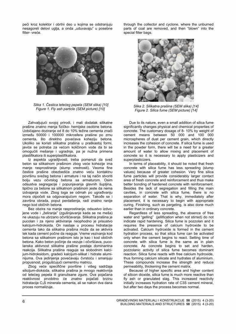
Čestice sitnije od 50µm uglavnom su sferične (slika1) dok krupnije čestice mogu da budu nepravilnijegoblika. Sferične čestice daju značajan doprinos fluidnosti betona u plastičnom stanju, optimizujući upakovanostčestica [1].
3.2 Silikatna prašina
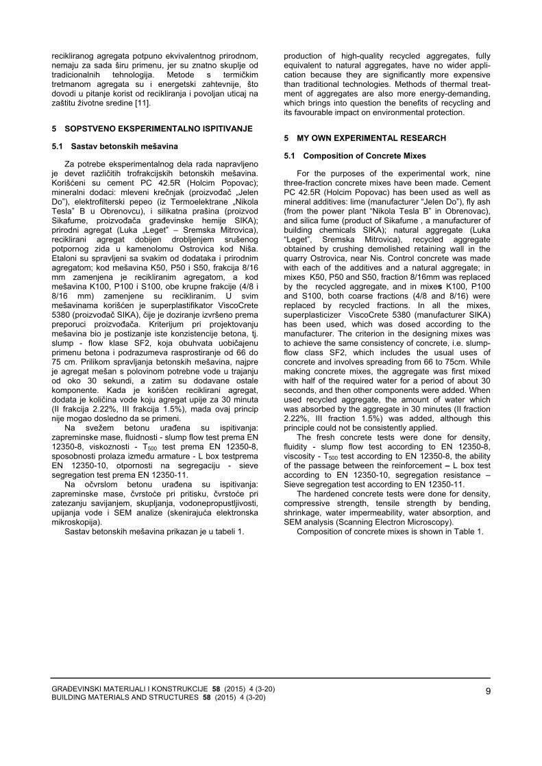
Silikatna prašina (slika 2) veoma je fin prah sledećihosobina:
1) sadržaj silicijum-dioksida, SiO2,najmanje 85%; 2) prosečna veličina čestica između 0.1 i 0.2
mikrona; 3) minimalna specifična površina 15000 m2/kg; 4) sferni oblik čestica.
Silikatna prašina nastaje prilikom topljenja kvarca navisokoj temperaturi u peći sa električnim lukom, pri čemunastaje silicijum ili ferosilicijum. Zbog ogromne količinepotrebne električne energije, ove peći se nalaze uzemljama sa značajnim elektropotencijalom poputskandinavskih zemalja, Sjedinjenih Država, Kanade,Južne Afrike i Australije. Kvarc visoke čistoće zagreva sedo 2000°C, gde se kao gorivo koriste ugalj, koks idrvena piljevina, a zatim uvodi električni luk da bi seizdvojili metali. Topljenjem kvarca oslobađa se silicijum-oksid u gasovitom stanju, koji se meša s kiseonikom uvišim delovima peći, gde oksidira, prelazeći u sićušnečestice amorfnog silicijum-dioksida. Čestice se izvode iz
reduction) compared to vibrated concrete. Properly designed and placed, SCC is characterized by a greater compactness and homogeneity compared with the vibrated concrete, wherein the properties of the hardened self-compacting concrete are tested in the same way as the corresponding properties of the vibrated concrete.
3 MINERAL ADDITIVES
3.1 Fly Ash
The initiators of the idea of applying fly ash, resulted from coal burning, in concrete were McMillan and Powers (1934). At the end of 40s the experiments carried out in the UK (Fulton and Marshal) led to the construction of dams Lednock, Clatworthy and Lubreoch, with fly ash as a cement additive. All thesestructures are after 60 years in excellent condition [10].
During the combustion of coal in a furnace at temperatures between 1250˚C and 1600˚C, non-combustible particles combine to form spherical glassy droplets of silicate (SiO2), aluminate (Al2O3), iron oxide (Fe2O3) and other less important constituents. When fly ash is added to concrete, pozzollanic reaction starts between silicon dioxide (SiO2) and calcium hydroxide (CaOH2) or lime, which is a by-product of hydration of Portland cement. The resulting products of hydration fill pores reducing the porosity of the matrix. These products differ from the products formed in concrete containing only Portland cement. In the reactions of Portland cement and water, hydrated lime (CaOH2) is formed first, in the space between particles, because of its limited solubility. In the presence of water, lime reacts pozzollanic with fly ash to form new hydration products with fine pore structures.
Particles smaller than 50-are generally spherical (Figure 1), while larger particles may be irregularly shaped. Spherical particles provide a significant contribution to the fluidity of concrete in the plastic state, optimizing the packing of particles [1].
3.2 Silica Fume
Silica fume (Figure 2) is very fine powder with the following characteristics:
1) the silica, SiO2, content of at least 85% 2) average particle size between 0.1 and 0.2
microns 3) minimum specific area 15 000 m2/kg 4) spherical shape of particles. Silica fume is formed during melting quartz at high
temperature in an electric arc furnace, wherein silicon or ferrosilicon occurs. Because of the huge amount of electricity needed, these furnaces are located in the countries with significant electrical potential, such as Scandinavian countries, USA, Canada, South Africa and Australia. High purity quartz is heated to 2000˚C using coal, coke or wood chips as fuel and then electric arc is introduced in order to remove metals. By melting quartz, silicon oxide is released in gaseous state, and it is mixed with oxygen in the upper parts of the furnace, where it oxidizes turning into tiny particles of amorphous silicon dioxide. Particles are carried out from the furnace
GRAĐEVINSKI MATERIJALI I KONSTRUKCIJE 58 (2015) 4 (3-20) BUILDING MATERIALS AND STRUCTURES 58 (2015) 4 (3-20)
6
peći kroz kolektor i obrtni deo u kojima se odstranjujunesagoreli delovi uglja, a onda „uduvavaju” u posebnefilter- vreće.
through the collector and cyclone, where the unburned parts of coal are removed, and then “blown” into the special filter bags.
Slika 1. Čestica letećeg pepela (SEM slika) [10] Figure 1. Fly ash particle (SEM picture) [10]
Slika 2. Silikatna prašina (SEM slika) [14] Figure 2. Silica fume (SEM picture) [14]
Zahvaljujući svojoj prirodi, i mali dodatak silikatneprašine znatno menja fizičko- hemijske osobine betona.Uobičajeno doziranje od 8 do 10% težine cementa značiizmeđu 50000 i 100000 mikrosfera prašine po zrnucementa, što direktno povećava koheziju betona.Ukoliko se koristi silikatna prašina u praškastoj formi,javiće se potreba za većom količinom vode da bi seomogućili mešanje i ugradnja, pa je nužna primenaplastifikatora ili superplastifikatora.
Iz aspekta ugradljivosti, treba pomenuti da svežbeton sa silikatnom prašinom zbog veće kohezije imamanje rasprostiranje (slump vrednosti). Veoma fine čestice prašine obezbediće znatno veću kontaktnupovršinu svežeg betona i armature i na taj način stvoritibolju vezu očvrslog betona sa armaturom. Osimodsustva segregacije i popunjavanja glavnih šupljina,tipično za betone sa silikatnom prašinom jeste da nema izdvajanja vode. Zbog toga se odmah po ugrađivanjumora otpočeti sa odgovarajućom negom. Takođe se izavršna obrada, poput perdašenja, radi znatno ranijenego kod običnih betona.
Bez obzira na manje rasprostiranje, odsustvo izdvo-jene vode i „želiranje” (zgušnjavanje kada se ne meša)ne ukazuju na ubrzano očvršćavanje. Silikatna prašina jepucolan i za njeno aktiviranje neophodno je prisustvokalcijum-hidroksida. On nastaje u procesu hidratacijecementa tako da silikatna prašina može da se aktiviratek kada cement počne da reaguje. Vreme vezivanja kodbetona sa silikatnom prašinom isto je kao i kod običnihbetona. Kako beton počinje da vezuje i očvršćava, puco-lanska aktivnost silikatne prašine postaje dominantnareakcija. Silikatna prašina reaguje sa slobodnim kalci-jum-hidroksidom, gradeći kalcijum-silikat i hidrate alumi-nijuma. Ova jedinjenja povećavaju čvrstoću i smanjujupropusnost, progušćujući cementnu matricu.
Zbog veće specifične površine i višeg sadržajasilicijum-dioksida, silikatna prašina je mnogo reaktivnijaod letećeg pepela ili granulisane zgure. Ova pojačanareaktivnost prvobitno će znatno pojačati brzinuhidratacije C3S minerala cementa, ali se nakon dva danaproces normalizuje.
Due to its nature, even a small addition of silica fume significantly changes physical and chemical properties of concrete. The customary dosage of 8- 10% by weight of cement means between 50 000 and 100 000 microspheres of dust per cement grain, which directly increases the cohesion of concrete. If silica fume is used in the powder form, there will be a need for a greater amount of water to allow mixing and placement of concrete so it is necessary to apply plasticizers and superplasticizers.
In terms of placeability, it should be noted that fresh concrete with silica fume has less spreading (slump values) because of greater cohesion. Very fine silica fume particles will provide considerably larger contact area of fresh concrete and reinforcement and thus make better bonding of hardened concrete with reinforcement. Besides the lack of segregation and filling the main cavities, in concrete with silica fume, there is no separation of water. That is why, immediately after placement, it is necessary to begin with appropriate curing. Finishing, such as pargeting, is also done much earlier than in ordinary concrete.
Regardless of less spreading, the absence of free water and “gelling” (jellification when not stirred) do not indicate rapid hardening. Silica fume is pozzolan and it requires the presence of calcium hydroxide to be activated. Calcium hydroxide is formed in the cement hydration process, so that silica fume can be activated only when the cement begins to react. Setting time of concrete with silica fume is the same as in plain concrete. As concrete begins to set and harden, pozzolanic activity of silica fume becomes dominant reaction. Silica fume reacts with free calcium hydroxide, thus forming calcium silicate and hydrates of aluminium. These compounds increase the strength and reduce permeability, thickening the cement matrix.
Because of higher specific area and higher content of silicon dioxide, silica fume is much more reactive than fly ash or granulated slag. This increased reactivity initially increases hydration rate of C3S cement mineral, but after two days the process becomes normal.

GRAĐEVINSKI MATERIJALI I KONSTRUKCIJE 58 (2015) 4 (3-20) BUILDING MATERIALS AND STRUCTURES 58 (2015) 4 (3-20)
7
3.3 Mleveni krečnjak
Mleveni krečnjak (slika 3) više se koristi kao dodatakcementu nego betonu. Evropska norma EN197 – 1 predviđa dve klase Portland cementa s krečnjakom čijesu oznake CEM II/A-L (ili L-L umesto A-L) i CEM II/B-L (ili L-L umesto B-L). Prvi sadrži između 6 i 20%krečnjaka, a drugi 21–35%.
3.3 Lime
Lime (Figure 3) is more widely used as a cement additive than a concrete additive. European norm EN197 - 1 provides two classes of Portland cement with lime whose labels are CEM II/L (or L-L instead of A-L) and CEM II/BL (or L-L instead of B-L). The former contains between 6 and 20% of lime and the latter 21- 35%.
Slika 3. Mleveni krečnjak (SEM slika)
Figure 3. Lime (SEM picture)
Zahtevi koje krečnjak za cement treba da ispuni jesusledeći: sadržaj CaCO3 mora da bude veći od 75%,sadržaj gline određen metilenskim plavim testom ne smeda pređe 1.20g /100 g, ukupni sadržaj organskog ugljenika ne sme da pređe 0.20% za LL krečnjak i 0.50%za L krečnjak.
Prisustvo krečnjaka izaziva ubrzanje hidratacionogprocesa i hidratacionog skupljanja betona već u prvihnekoliko sati, zbog toga što čestice krečnjaka služe kaododatna jezgra za hidrataciju.
4 RECIKLIRANI AGREGAT
Kao održivo rešenje za probleme građevinskogotpada i iscrpljivanje nalazišta prirodnih agregata,nametnuo se postupak recikliranja deponovanihgrađevinskih materijala, u prvom redu betona.Recikliranje i očuvanje prirodnih resursa bezrezervno suprihvaćeni od strane građevinske industrije, ali pozitivniefekti takvog pristupa donekle su ograničeni, zato štonisu obezbeđeni svi uslovi za primenu. To seprvenstveno odnosi na nedostatak: prostora i opreme zasortiranje građevinskog šuta, iskustva u postupcimarecikliranja otpadnih materijala, obučenih radnika ikontrolora, znanja o tržištu sekundarnih materijala,zakonske regulative u oblasti zaštite životne sredine, itako dalje [7].
Upotreba recikliranog agregata u konstrukcijama još je relativno nova priča. Njen početak Bak (Buck, 1977)smešta u period neposredno nakon Drugog svetskograta, kada je postojala ogromna potreba da se gradenovi objekti i infrastruktura i istovremeno raščišćavajupostojeće ruševine. Nakon toga, reciklirani agregatprestaje da se upotrebljava, da bi tokom sedamdesetihgodina, Sjedinjene Države počele ponovo da koristereciklirani agregat u nekonstrukcijske svrhe, mahom kaomaterijal za ispunu i različita nasipanja u putarstvu [8].Zbog razloga koji su napred navedeni, ispitivanje
Requirements that lime for cement should meet are the following: CaCO3 content should be greater than 75%, clay content, determined by methylene blue test, must not exceed 1.20g/100g, the total content of organic carbon must not exceed 0.20% for LL lime and 0.50% for L lime.
The presence of lime causes the acceleration of the hydration process and hydration shrinkage of concrete in the first few hours, because the particles of lime are used as additional cores for hydration.
4 RECYCLED AGGREGATE
As a sustainable solution to the problems of construction waste and the depletion of natural aggregates sites, the recycling process of deposited building materials, primarily concrete, has been imposed. Recycling and preservation of natural resources are unreservedly accepted by the construction industry but positive effects of this approach are somewhat limited, since the conditions for their application are still concealed. This is primarily related to the lack of space equipment for sorting construction rubble, lack of experience in the procedures of recycling waste materials, shortage of skilled workers and supervisors, lack of knowledge of the secondary materials market, of legislation in the field ofenvironmental protection, etc [7].
The use of recycled aggregates in structures is still relatively new. Buck (1977) defines its beginning in the period immediately after the Second World War, when there was a tremendous need for building new facilities and infrastructure and at the same time, clearing the existing ruins. After that, the use of recycled aggregates stopped but during 70s the US started to re-use recycled aggregates in non-construction purposes, mainly as fill material and different fillings in road engineering [8]. Due to the above mentioned reasons, testing of recycled

GRAĐEVINSKI MATERIJALI I KONSTRUKCIJE 58 (2015) 4 (3-20) BUILDING MATERIALS AND STRUCTURES 58 (2015) 4 (3-20)
8
recikliranog agregata (ne samo betonskog) i njegovaprimena danas su aktuelniji no ikad, jer je potreba zaagregatom na svetskom nivou dostigla 26.8 milijardi tonagodišnje [15]. Primera radi, Sjedinjene Države godišnjerecikliraju oko 140 miliona tona betonskog otpada.Prema podacima iz godišnjeg izveštaja Evropskeasocijacije za agregat (2010), reciklirani agregat čini 5%ukupne proizvodnje agregata u Evropskoj uniji, gde jeNemačka najveći proizvođač (60 miliona tona), a slede Velika Britanija (49 miliona tona), Holandija (20 milionatona) i Francuska (17 miliona tona). U Australiji se oko50% betonskog otpada reciklira, dok se u Japanuimpozantnih 98% betonskog otpada pretvara u recikliraniagregat [5].
Procenjuje se da u Republici Srbiji godišnje nastajeoko milion tona građevinskog otpada i otpada odrušenja. Ovaj otpad završava na deponijamakomunalnog otpada, a koristi se i kao inertan materijalza prekrivanje otpada na deponiji. Reciklažagrađevinskog otpada praktično ne postoji [12].
Tehnološki postupak proizvodnje recikliranogagregata podrazumeva drobljenje komada starog betonana zrna određene veličine i njihovo prosejavanje, čemuprethodi odvajanje metalnih delova magnetnimseparatorom i ručno ili mašinsko uklanjanje stranihmaterija. Zrno recikliranog agregata dobijeno ovakvimpostupkom recikliranja sastoji se od zrna (ili dela zrna)prirodnog agregata i cementnog maltera originalnogbetona, koji ga delimično ili potpuno obavija. Prisustvostarog cementnog maltera, koji je manje zapreminskemase i veće poroznosti od zrna prirodnog agregata,značajno utiče na niz fizičko-mehaničkih svojstava, kakorecikliranog agregata, tako i betona na bazi recikliranogagregata, odnosno uslovljava „lošija” svojstvarecikliranog u odnosu na prirodni agregat. Zbog toga suse u svetu u poslednjih nekoliko godina razvilaistraživanja u smislu unapređivanja tehnologijerecikliranja i dobijanja recikliranog agregata koji bi posvojstvima, odnosno kvalitetu, bio praktično identičanprirodnom agregatu. Radi uklanjanja cementnog kamenasa zrna agregata razvijeno je nekoliko naprednihtehnologija recikliranja, pre svega u Japanu. Jedna odtih tehnologija jeste takozvana „metoda zagrevanja istruganja”. Na ovaj način, dobija se 35% do 45% čistog krupnog agregata, 30% do 35% čistog sitnog i 18% do35% finog praha od cementnog maltera u zavisnosti odtemperature zagrevanja (300-700˚C).
Druga tehnologija je hemijski tretman klasičnoproizvedenog recikliranog agregata. Prethodnimpotapanjem recikliranog agregata u blage rastvorehlorovodonične, sumporne ili fosforne kiseline moguće jeodstraniti deo cementnog maltera i poboljšati svojstvaagregata, bez značajnijeg povećanja sadržaja hlorida isulfata u njemu. Pomenuta procedura sastoji se izpotapanja recikliranog agregata u kiselu sredinu utrajanju od 24h, pri temperaturi od oko 20˚C, a zatim sevrši ispiranje destilovanom vodom kako bi se u najvećojmogućoj meri uklonile primenjene kiseline. Pre samogspravljanja betona, agregat stoji u vodi 24 časa. Da sene bi smanjio kvalitet agregata (pH vrednost),koncentracija kiseline u rastvoru treba da bude oko 0.1mol. Ovim postupkom moguće je smanjiti upijanje vodekod recikliranog agregata za 7–12% [9,6]. Sve navedene napredne tehnologije recikliranja, odnosno poboljšanjakvaliteta, iako omogućavaju proizvodnju kvalitetnog
aggregates (not just concrete) and their application are more relevant today than ever, because the need for aggregates globally reached 26.8 billion tons per year [15]. For example, the US annually recycles about 149 million tons of concrete waste. According to the data from the annual report of the European Association for aggregates (2010), recycled aggregates make 5% of the total production of aggregates in the European Union, where Germany is the largest producer, followed by Great Britain (49 million tons), the Netherlands (20 million tons) and France (17 million tons). In Australia, around 50% of the concrete waste is recycled, while in Japan, the impressive 98% of concrete waste is turnedinto recycled aggregate [5].
It is estimated that in the Republic of Serbia, about 1 million tons of construction waste and demolition waste is annually produced. This waste ends up in landfills of municipal waste, and is also used as inert material for coverage of waste at landfills. Recycling construction waste actually does not exist [12].
Technological process for the production of recycled aggregates involves crushing pieces of old concrete to a certain grain size and their sieving, which is preceded by the separation of metal parts, using magnetic separator, and manual or mechanical removal of foreign substances. Grains of recycled aggregate, obtained by this recycling process, consist of grains (or grain parts) of natural aggregates and cement mortar of original concrete which partially or completely wraps them. The presence of old cement mortar, which is of less density and higher porosity than grains of natural aggregates, significantly affects a number of physical and mechanical properties, of both recycled aggregate and concrete with recycled aggregate, i.e. causes “ worse” properties of recycled aggregate compared to natural aggregate. Therefore, numerous researches have been carried out worldwide with the aim of improving recycling techno-logies and obtaining recycled aggregates that would be practically identical to natural aggregate in their properties or quality. In order to remove cement stone from an aggregate grain, a number of advanced recycling technologies have been developed, primarily in Japan. One of these technologies is called “the method of heating and abrasion”. Thus, they obtain 35% to 45% of pure coarse aggregate, 30% to 35% of pure smallaggregate, and 18 % to 35% of fine powder of cement mortar, depending on the heating temperature (300 –700˚C).
Other technology is chemical treatment of classically produced recycled aggregate. By previous submerging of recycled aggregate in a mild solution of hydrochloric, phosphoric and sulphuric acid, it is possible to remove a part of cement mortar and improve aggregate properties without a significant increase of the content of chloride and sulphate in it. The mentioned procedure consists of immersing recycled aggregate in an acidic environment for 24 hours at a temperature of about 20˚C, and then the applied acids are removed to the maximum extent possible, by washing with distilled water. Before making concrete, aggregate is left in water for 24 hours. In order to sustain the quality of the aggregate (ph value), con-centration of acid in solution should be about 0.1mol. This method can reduce the absorption of water in recycled aggregate for 7-12% [9,6]. All of these advanced recycling technologies, although enable the
GRAĐEVINSKI MATERIJALI I KONSTRUKCIJE 58 (2015) 4 (3-20) BUILDING MATERIALS AND STRUCTURES 58 (2015) 4 (3-20)
9
recikliranog agregata potpuno ekvivalentnog prirodnom,nemaju za sada širu primenu, jer su znatno skuplje odtradicionalnih tehnologija. Metode s termičkimtretmanom agregata su i energetski zahtevnije, što dovodi u pitanje korist od recikliranja i povoljan uticaj nazaštitu životne sredine [11].
5 SOPSTVENO EKSPERIMENTALNO ISPITIVANJE
5.1 Sastav betonskih mešavina
Za potrebe eksperimentalnog dela rada napravljenoje devet različitih trofrakcijskih betonskih mešavina.Korišćeni su cement PC 42.5R (Holcim Popovac);mineralni dodaci: mleveni krečnjak (proizvođač „JelenDo”), elektrofilterski pepeo (iz Termoelektrane „NikolaTesla” B u Obrenovcu), i silikatna prašina (proizvodSikafume, proizvođača građevinske hemije SIKA);prirodni agregat (Luka „Leget” – Sremska Mitrovica),reciklirani agregat dobijen drobljenjem srušenogpotpornog zida u kamenolomu Ostrovica kod Niša.Etaloni su spravljeni sa svakim od dodataka i prirodnimagregatom; kod mešavina K50, P50 i S50, frakcija 8/16mm zamenjena je recikliranim agregatom, a kodmešavina K100, P100 i S100, obe krupne frakcije (4/8 i8/16 mm) zamenjene su recikliranim. U svimmešavinama korišćen je superplastifikator ViscoCrete5380 (proizvođač SIKA), čije je doziranje izvršeno premapreporuci proizvođača. Kriterijum pri projektovanjumešavina bio je postizanje iste konzistencije betona, tj.slump - flow klase SF2, koja obuhvata uobičajenuprimenu betona i podrazumeva rasprostiranje od 66 do75 cm. Prilikom spravljanja betonskih mešavina, najpreje agregat mešan s polovinom potrebne vode u trajanjuod oko 30 sekundi, a zatim su dodavane ostalekomponente. Kada je korišćen reciklirani agregat,dodata je količina vode koju agregat upije za 30 minuta(II frakcija 2.22%, III frakcija 1.5%), mada ovaj principnije mogao dosledno da se primeni.
Na svežem betonu urađena su ispitivanja:zapreminske mase, fluidnosti - slump flow test prema EN 12350-8, viskoznosti - T500 test prema EN 12350-8, sposobnosti prolaza između armature - L box testpremaEN 12350-10, otpornosti na segregaciju - sieve segregation test prema EN 12350-11.
Na očvrslom betonu urađena su ispitivanja:zapreminske mase, čvrstoće pri pritisku, čvrstoće prizatezanju savijanjem, skupljanja, vodonepropustljivosti,upijanja vode i SEM analize (skenirajuća elektronskamikroskopija).
Sastav betonskih mešavina prikazan je u tabeli 1.
production of high-quality recycled aggregates, fully equivalent to natural aggregates, have no wider appli-cation because they are significantly more expensive than traditional technologies. Methods of thermal treat-ment of aggregates are also more energy-demanding, which brings into question the benefits of recycling and its favourable impact on environmental protection.
5 MY OWN EXPERIMENTAL RESEARCH
5.1 Composition of Concrete Mixes
For the purposes of the experimental work, nine three-fraction concrete mixes have been made. Cement PC 42.5R (Holcim Popovac) has been used as well as mineral additives: lime (manufacturer “Jelen Do”), fly ash (from the power plant “Nikola Tesla B” in Obrenovac), and silica fume (product of Sikafume , a manufacturer of building chemicals SIKA); natural aggregate (Luka “Leget”, Sremska Mitrovica), recycled aggregate obtained by crushing demolished retaining wall in the quarry Ostrovica, near Nis. Control concrete was made with each of the additives and a natural aggregate; in mixes K50, P50 and S50, fraction 8/16mm was replaced by the recycled aggregate, and in mixes K100, P100 and S100, both coarse fractions (4/8 and 8/16) were replaced by recycled fractions. In all the mixes, superplasticizer ViscoCrete 5380 (manufacturer SIKA) has been used, which was dosed according to the manufacturer. The criterion in the designing mixes was to achieve the same consistency of concrete, i.e. slump-flow class SF2, which includes the usual uses of concrete and involves spreading from 66 to 75cm. While making concrete mixes, the aggregate was first mixedwith half of the required water for a period of about 30 seconds, and then other components were added. When used recycled aggregate, the amount of water which was absorbed by the aggregate in 30 minutes (II fraction 2.22%, III fraction 1.5%) was added, although this principle could not be consistently applied.
The fresh concrete tests were done for density, fluidity - slump flow test according to EN 12350-8, viscosity - T500 test according to EN 12350-8, the ability of the passage between the reinforcement – L box testaccording to EN 12350-10, segregation resistance –Sieve segregation test according to EN 12350-11.
The hardened concrete tests were done for density, compressive strength, tensile strength by bending, shrinkage, water impermeability, water absorption, and SEM analysis (Scanning Electron Microscopy).
Composition of concrete mixes is shown in Table 1.
GRAĐEVINSKI MATERIJALI I KONSTRUKCIJE 58 (2015) 4 (3-20) BUILDING MATERIALS AND STRUCTURES 58 (2015) 4 (3-20)
10
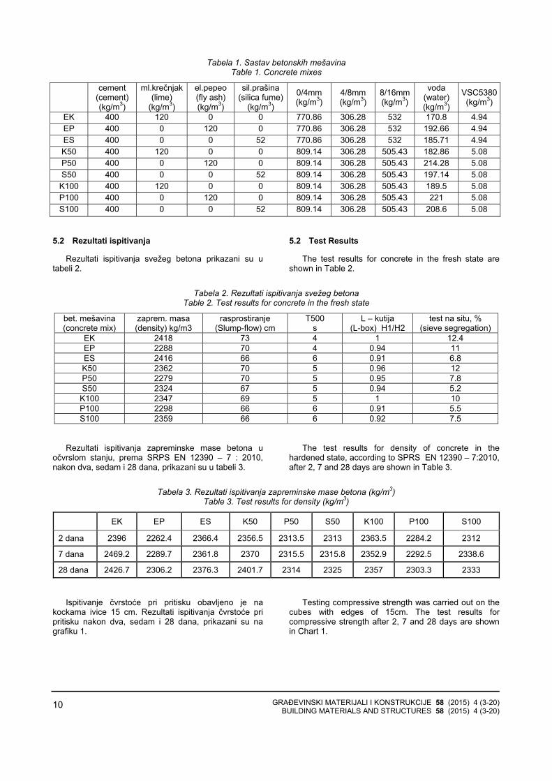
Tabela 1. Sastav betonskih mešavina Table 1. Concrete mixes
cement
(cement) (kg/m3)
ml.krečnjak (lime)
(kg/m3)
el.pepeo (fly ash) (kg/m3)
sil.prašina (silica fume)
(kg/m3)
0/4mm (kg/m3)
4/8mm (kg/m3)
8/16mm (kg/m3)
voda (water) (kg/m3)
VSC5380(kg/m3)
EK 400 120 0 0 770.86 306.28 532 170.8 4.94 EP 400 0 120 0 770.86 306.28 532 192.66 4.94 ES 400 0 0 52 770.86 306.28 532 185.71 4.94 K50 400 120 0 0 809.14 306.28 505.43 182.86 5.08 P50 400 0 120 0 809.14 306.28 505.43 214.28 5.08 S50 400 0 0 52 809.14 306.28 505.43 197.14 5.08 K100 400 120 0 0 809.14 306.28 505.43 189.5 5.08 P100 400 0 120 0 809.14 306.28 505.43 221 5.08 S100 400 0 0 52 809.14 306.28 505.43 208.6 5.08
5.2 Rezultati ispitivanja
Rezultati ispitivanja svežeg betona prikazani su utabeli 2.
5.2 Test Results
The test results for concrete in the fresh state are shown in Table 2.
Tabela 2. Rezultati ispitivanja svežeg betona Table 2. Test results for concrete in the fresh state
bet. mešavina (concrete mix)
zaprem. masa (density) kg/m3
rasprostiranje (Slump-flow) cm
T500 s
L – kutija (L-box) H1/H2
test na situ, % (sieve segregation)
EK 2418 73 4 1 12.4 EP 2288 70 4 0.94 11 ES 2416 66 6 0.91 6.8 K50 2362 70 5 0.96 12 P50 2279 70 5 0.95 7.8 S50 2324 67 5 0.94 5.2 K100 2347 69 5 1 10 P100 2298 66 6 0.91 5.5 S100 2359 66 6 0.92 7.5
Rezultati ispitivanja zapreminske mase betona uočvrslom stanju, prema SRPS EN 12390 – 7 : 2010,nakon dva, sedam i 28 dana, prikazani su u tabeli 3.
The test results for density of concrete in the hardened state, according to SPRS EN 12390 – 7:2010, after 2, 7 and 28 days are shown in Table 3.
Tabela 3. Rezultati ispitivanja zapreminske mase betona (kg/m3) Table 3. Test results for density (kg/m3)
EK EP ES K50 P50 S50 K100 P100 S100
2 dana 2396 2262.4 2366.4 2356.5 2313.5 2313 2363.5 2284.2 2312
7 dana 2469.2 2289.7 2361.8 2370 2315.5 2315.8 2352.9 2292.5 2338.6
28 dana 2426.7 2306.2 2376.3 2401.7 2314 2325 2357 2303.3 2333
Ispitivanje čvrstoće pri pritisku obavljeno je nakockama ivice 15 cm. Rezultati ispitivanja čvrstoće pripritisku nakon dva, sedam i 28 dana, prikazani su na grafiku 1.
Testing compressive strength was carried out on the cubes with edges of 15cm. The test results for compressive strength after 2, 7 and 28 days are shown in Chart 1.
GRAĐEVINSKI MATERIJALI I KONSTRUKCIJE 58 (2015) 4 (3-20) BUILDING MATERIALS AND STRUCTURES 58 (2015) 4 (3-20)
11
ČVRSTOĆA PRI PRITISKU
0
1020
30
40
5060
70
80
EK EP ES K50 P50 S50 K100 P100 S100
Betonska mešavina
Vre
dnos
t čvr
stoć
e (M
Pa)
2 dana
7 dana
28 dana
Grafik 1. Čvrstoća pri pritisku
Chart 1. Compressive strength
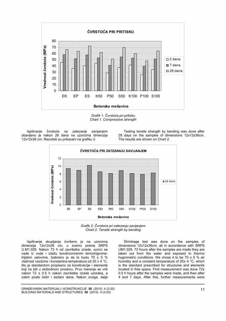
Ispitivanje čvrstoće na zatezanje savijanjemobavljeno je nakon 28 dana na uzorcima dimenzija12x12x36 cm. Rezultati su prikazani na grafiku 2.
Testing tensile strength by bending was done after 28 days on the samples of dimensions 12x12x36cm. The results are shown on Chart 2.
ČVRSTOĆA PRI ZATEZANJU SAVIJANJEM
0
2
4
6
8
10
12
EK EP ES K50 P50 S50 K100 P100 S100
Betonska mešavina
Vred
nost
čvr
stoć
e (M
Pa)
28 dana
Grafik 2. Čvrstoća pri zatezanju savijanjem
Chart 2. Tensile strength by bending
Ispitivanje skupljanja izvršeno je na uzorcimadimenzija 12x12x36 cm, u svemu prema SRPSU.M1.029. Nakon 72 h od završetka izrade, uzorci sevade iz vode i izlažu kondicioniranim termohigrome-trijskim uslovima. Izabrano je da to budu 70 ± 5 %vlažnost vazduha i konstantna temperatura od 20 ± 4 °C,što je standardom propisano za konstrukcije i elementekoji će biti u slobodnom prostoru. Prvo merenje se vršinakon 72 ± 0.5 h nakon završetka izrade uzoraka, azatim posle četiri i sedam dana. Nakon ovoga, dalja
Shrinkage test was done on the samples of dimensions 12x12x36cm, all in accordance with SRPS UM1.029. 72 hours after the samples are made they are taken out from the water and exposed to thermo hygrometric conditions. We chose it to be 70 ± 5 % air humidity and a constant temperature of 20± 4 °C, which is the standard prescribed for structures and elements located in free space. First measurement was done 72± 0.5 h hours after the samples were made, and then after 4 and 7 days. After this, further measurements were

GRAĐEVINSKI MATERIJALI I KONSTRUKCIJE 58 (2015) 4 (3-20) BUILDING MATERIALS AND STRUCTURES 58 (2015) 4 (3-20)
12
merenja rade se nakon svakih narednih sedam dana, dok se proces ne stabilizuje. Rezultati ispitivanjaskupljanja betona nakon četiri, sedam, 14, 21, 28 i 35dana prikazani su na grafiku 3.
done after every seven days, until the process stabilized. The results of shrinkage tests after 4, 7, 14, 21, 28, and 35 days, are shown in Chart 3.
SKUPLJANJE BETONA
0
50
100
150
200
250
300
350
400
450
EK EP ES K50 P50 S50 K100 P100 S100
Betonska mešavina
Skup
ljanj
e (u
10-3
mm
/m)
4
7
14
21
28
35
Grafik 3. Skupljanje betona
Chart 3. Shrinkage
Ispitivanje upijanja vode urađeno je na uzorcima
dimenzija 12x12x36 cm, metodom postupnog potapanja.Rezultati ispitivanja upijanja vode nakon 28 danaprikazani su na grafiku 4.
Water absorption test was done on the samples of dimensions 12x12x36cm, by the method of gradual immersion. The test results for water absorption after 28 days are shown in Chart 4.
Grafik 4. Upijanje vode
Chart 4. Water absorption
Ispitivanje vodonepropustljivosti rađeno je na uzor-
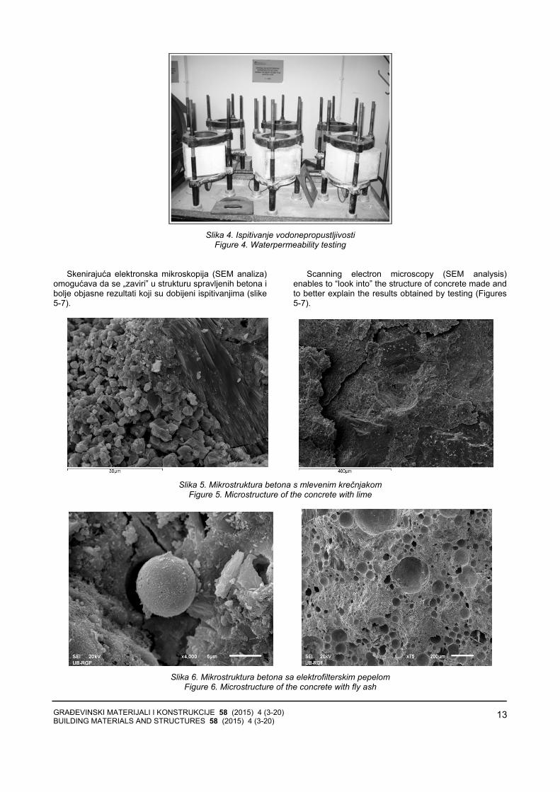
cima dimenzija 200x200x150 mm, pri starosti betona od28 dana, u svemu prema SRPS U.M1.015:1998. Uzorcisu 24 časa izloženi dejstvu vode pod pritiskom od 1bara, sledećih 48 časova pritisku od 3 bara, i na krajuposlednja 24 časa ispitivanja, pritisku od 7 bara. Nakonovoga se polome i meri se dubina prodora vode. Koduzoraka s krečnjakom i silikatnom prašinom, zabeleženje prodor vode od oko 2 cm, dok je kod uzoraka s pepelom prodor vode iznosio 8-10 cm.
Water permeability testing was done on the samples of dimensions 200x200x150mm, in concrete at an age of 28 days, all in accordance with SRPS U.M1.015:1998. The samples were exposed to water under pressure of 1 bar for 24 hours; then the following 48 hours of 3 bars and finally, the last 24 hours of testing, under pressure of 7 bars. After this, they werebroken and the depth of water ingress is measured. With the samples with lime and silica fume, ingress of water of about 2cm was recorded, while with the samples with fly ash, ingress of water was 8-10 cm.
GRAĐEVINSKI MATERIJALI I KONSTRUKCIJE 58 (2015) 4 (3-20) BUILDING MATERIALS AND STRUCTURES 58 (2015) 4 (3-20)
13
Slika 4. Ispitivanje vodonepropustljivosti
Figure 4. Waterpermeability testing
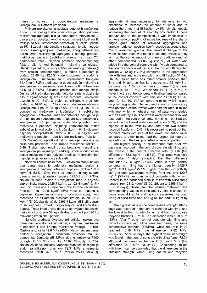
Skenirajuća elektronska mikroskopija (SEM analiza)
omogućava da se „zaviri” u strukturu spravljenih betona ibolje objasne rezultati koji su dobijeni ispitivanjima (slike5-7).
Scanning electron microscopy (SEM analysis) enables to “look into” the structure of concrete made and to better explain the results obtained by testing (Figures 5-7).
Slika 5. Mikrostruktura betona s mlevenim krečnjakom
Figure 5. Microstructure of the concrete with lime
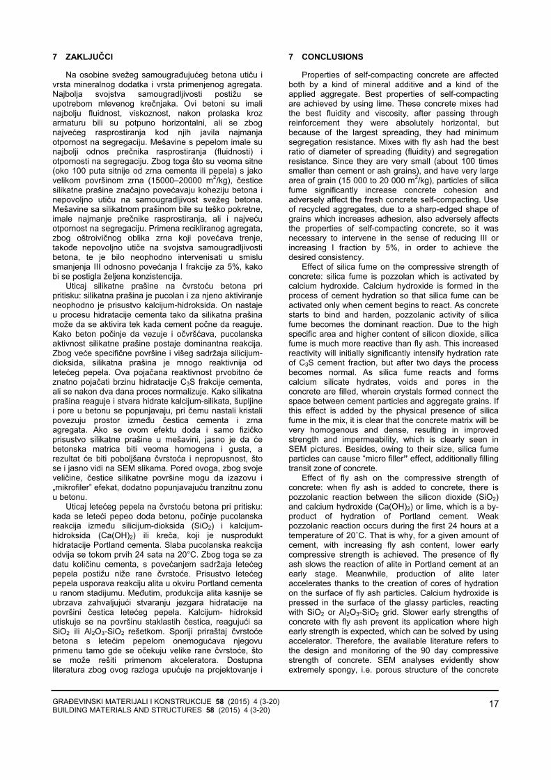
Slika 6. Mikrostruktura betona sa elektrofilterskim pepelom
Figure 6. Microstructure of the concrete with fly ash

GRAĐEVINSKI MATERIJALI I KONSTRUKCIJE 58 (2015) 4 (3-20) BUILDING MATERIALS AND STRUCTURES 58 (2015) 4 (3-20)
14
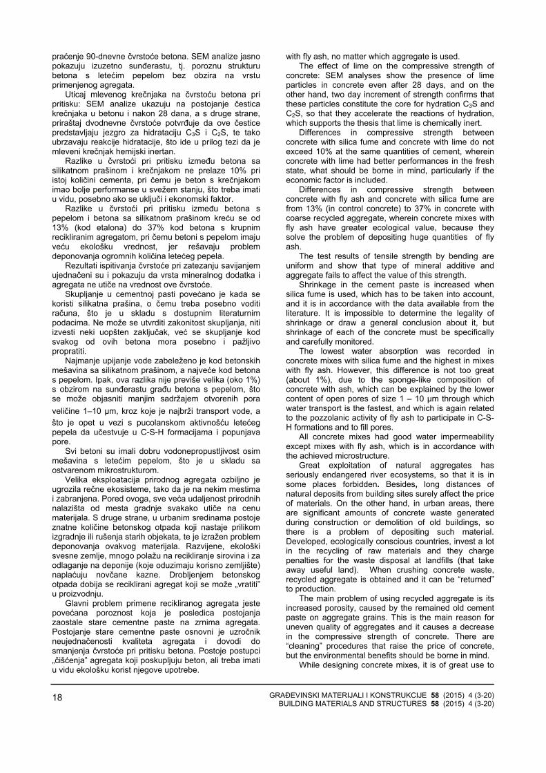
Slika 7. Mikrostruktura betona sa silikatnom prašinom
Figure 7. Microstructure of the concrete with silica fume 6 ANALIZA REZULTATA
Rasprostiranje svežeg betona iznosilo je od 66 do 73cm, što sve projektovane mešavine svrstava u klasuSF2, koja odgovara najčešćoj primeni betona ugrađevinarstvu. Najmanju pokretljivost imale su betonske mešavine sa silikatnom prašinom, kao imešavine s recikliranim agregatom, jer je oštroivičnozrno ovog agregata teže „pomeriti” prilikom razlivanjabetona. Najveće rasprostiranje izmereno je kod etalonas krečnjakom - 73 cm, a najmanje kod etalona sasilikatnom prašinom, mešavine sa silikatnom prašinom ikrupnim recikliranim agregatom i mešavine s pepelom ikrupnim recikliranim agregatom - 66 cm.
T500 je vreme za koje beton dostigne 500 mm, a merise prilikom izvođenja slump-flow testa. Predstavljaproveru viskoznosti mešavine; za klasu SF2 preporučujese interval od 3.5 do 6.0 s, u koji se sve mešavine„uklapaju”. Rezultati su u opsegu od 4 do 6 s, pri čemusu najsporije bile betonske mešavine sa silikatnomprašinom. Vreme duže od 2 s svrstava ih u klasuviskoznosti VS2.
Sve mešavine zadovoljavaju kriterijum da odnosvisina betona na krajevima L-boxa bude najmanje 0.8, a kako je ispitivanje rađeno s tri armaturne šipke (što je izahtev za gušće armirane konstrukcije), njihova klasa jePA2 (engl. passing ability = sposobnost prolaza).Rezultati testa kreću se u opsegu 0.91 – 1.0, pri čemusu najbolje rezultate (najbliže 1.0) postigle mešavine skrečnjakom. Najveća razlika na krajevima L box-a izmerena je kod mešavina sa silikatnom prašinom, što jei logična posledica njihovog najmanjeg rasprostiranja. Niu jednom slučaju nije zabeleženo zaglavljivanje zrnaagregata između šipki armature.
Test na situ pokazao je da su sve mešavine otpornena segregaciju i pripadaju klasi SR2 (<15%), pri čemuveće rasprostiranje znači manju otpornost na segregaciju.
Najveću zapreminsku masu u svežem stanju imao jeetalon s krečnjakom 2418 kg/m3, gotovo istu kao i etalonsa silikatnom prašinom (2416 kg/m3, tj. za 0.08% manju), dok je najmanja zapreminska masa određena kodmešavine P50 (pepeo i reciklirana III frakcija) 2279kg/m3 za 5.7% manja. Uopšte, mešavine s pepelomimale su najmanje zapreminske mase, oko 70 kg/m3
6 THE RESULTS ANALYSIS
Fresh concrete was spread from 66 to 73cm which designed mixes of class SF2 which fits in most common use of concrete in construction. Mixes with silica fume had the slightest mobility, as well as mixes with recycled aggregate, because grains with sharp edges were more difficult to” move” while levelling concrete. The largest spreading was recorded in control concrete with lime -73cm, and the smallest in control concrete with silica fume, in mixes with silica fume and coarse recycled aggregate, and in mixes with fly ash and coarse recycled aggregate - 66.
T500 is the time that concrete reaches 500mm, and it is measured when doing slump-flow test. It represents a check of viscosity of the mix; the recommended interval for class SF2 is from 3.5 to 6.0s, and all mixes “fit” into it. The results are in the range of 4 – 6s, wherein concrete mixes with silica fume were the slowest. Time longer than 2s puts them in viscosity class VS2.
All mixes meet the criterion that height ratio of concrete at the ends of L-box is at least 0.8 and their class is PA2 as the testing was done with three reinforcement rods which is a requirement for thicker reinforced construction. The test scores are in the range of 0.91 – 1.0, wherein mixes with lime achieved the best results (nearest to 1.0). The biggest difference at the ends of L box was measured in mixes with silica fume, which is a logical consequence of its minimum spreading. Blocking of aggregate grains between reinforcement rods was not recorded in any case.
Sieve test shows that all mixes are resistant to segregation and they belong to class SR2 (<15%), while larger spreading means lower resistance to segregation.
Control concrete with lime had the highest density in the fresh state, 2418 kg/m3, nearly the same as the control concrete with silica fume (2416 kg/m3, i.e. 0.08 lower), while minimum density was found in the mix P50 (fly ash and recycled III fraction) 2279 kg/m3, 5.7% lower. Generally speaking, mixes with fly ash had the lowest density, about 70 kg/m3 lower, compared to the corresponding mixes with lime and silica fume.
While designing concrete mixes, in order to obtain the same consistency because of the use of recycled
GRAĐEVINSKI MATERIJALI I KONSTRUKCIJE 58 (2015) 4 (3-20) BUILDING MATERIALS AND STRUCTURES 58 (2015) 4 (3-20)
15
manje u odnosu na odgovarajuće mešavine skrečnjakom i silikatnom prašinom.
Prilikom projektovanja sastava betonskih mešavina,a da bi se postigla ista konzistencija, zbog primenerecikliranog agregata bilo je neophodno intervenisati udva pravca: povećati količinu vode i smanjiti količinu IIIfrakcije za 5%, istovremeno povećavajući količinu peskaza 5%. Bez ovih intervencija u sastavu, nije bilo moguće postići samougradljivost mešavine, zbog oštroivičnogoblika zrna recikliranog agregata i samog granulo-metrijskog sastava (reciklirani agregat je imao 7%nadmerenih zrna). Najveća promena vodocementnogfaktora bila je kod betonskih mešavina sa elektro-filterskim pepelom, pri istoj količini mineralnog dodatka (isvim ostalim komponentama), u etalon s pepelom jedodato 21.86 kg (12.8%) vode u odnosu na etalon skrečnjakom; u mešavinu sa III recikliranom frakcijom31.42 kg (17.2%) u odnosu na odgovarajuću mešavinu skrečnjakom, a u mešavinu s recikliranom II i III frakcijom31.5 kg (16.6%). Silikatna prašina ima mnogo sitniječestice od krečnjaka i pepela, tako da je njeno doziranjebilo 52 kg/m3 betona, tj. 13% mase cementa (uobičajena dozaža je 10–15%). U etalon sa silikatnom prašinomdodato je 14.91 kg (8.7%) vode u odnosu na etalon skrečnjakom, i po 14.28 kg (7.8%) i 19.1 kg (10.1%) uodnosu na mešavine s krečnjakom i recikliranimagregatom. Zahtevana klasa konzistencije postignuta je pri najmanjem vodocementnom faktoru kod mešavina skrečnjakom, dok je najviše vode bilo potrebno kodmešavina s pepelom. Najmanji vodocementni faktorzabeležen je kod etalona s krečnjakom – 0.43 (ujedno inajmanji vodopraškasti faktor – 0.33), a najveći kod mešavine s pepelom i obe krupne reciklirane frakcije –0.55. Najveći vodopraškasti faktor imala je mešavina sasilikatnom prašinom i obe krupne reciklirane frakcije –0.46. Treba napomenuti da su betonske mešavine skrečnjakom pri najmanjem sadržaju vode u odnosu naostale mešavine imale najveće prečnike rasprostiranja inajbolja svojstva samougradljivosti.
Najveću zapreminsku masu u očvrslom stanju nakondva dana imala je betonska mešavina etalon skrečnjakom, a najmanju etalon s pepelom (razlika 133.6 kg/m3 tj. 5.6%). Ovaj trend se održao i nakon sedamdana s tim što je razlika iznosila 179.5 kg/m3 (7.3%). Nakon 28 dana, etalon s krečnjakom imao je najvećuzapreminsku masu, 2426.7 kg/m3, za 123.4 kg/m3 (5.1%) veću od mešavine s pepelom i obe krupne recikliranefrakcije, i za 120.5 kg/m3 (5%) veću od etalona spepelom. Zapreminska masa u očvrslom stanju kodmešavina sa silikatnom prašinom kretala se od 2312kg/m3 (S100, dva dana) do 2366.4 kg/m3 (ES, 28 dana);to su vrednosti „između” odgovarajućih kod krečnjaka ipepela. Treba imati u vidu da je za spravljanje betonskihmešavina korišćeno 52 kg silikatne prašine i po 120 kgmlevenog krečnjaka i pepela.
Najveću vrednost čvrstoće pri pritisku, nakon dvadana imao je etalon s krečnjakom, a najmanju mešavina s pepelom i obe krupne reciklirane frakcije – P100. Razlika je iznosila 19.8 MPa (43%). Nakon sedam dana,etaloni s krečnjakom i silikatnom prašinom imali sugotovo iste čvrstoće (58 MPa), dok je mešavina P100dostigla 40.18 MPa (razlika 17.82 MPa, tj. 30.7%).Nakon 28 dana, najveću vrednost čvrstoće dostigao jeetalon sa silikatnom prašinom, 72.31 MPa, a najmanjumešavina P100, 47.2 MPa (razlika 25.11 MPa, tj.
aggregate, it was necessary to intervene in two directions: to increase the amount of water and to reduce the amount of III fraction by 5%, simultaneously increasing the amount of sand by 5%. Without theseinterventions in the composition, it was impossible to achieve self-compacting of mixes because of the sharp-edged grain shape of recycled aggregates and granulometric composition itself (recycled aggregate had 7% of oversized grains). The greatest change of the water- cement ratio was found in concrete mixes with fly ash; at the same amount of mineral additive (and all other components), 21.86 kg (12.8%) of water was added into the control concrete with fly ash compared to the control concrete with lime; in the mix with III recycled fraction 31.42 kg (17.2%) compared to the appropriate mix with lime and in the mix with I and III fraction 31.5 kg (16.6%). Silica fume has much smaller particles than lime and fly ash, so that its dosage was 52 kg/m3 of concrete, i.e. 13% by the mass of cement (the usual dosage is 10 – 15%). We added 14.91 kg (8.7%) of water into the control concrete with silica fume compared to the control concrete with lime and 14.28 kg (7.8%) and 19.1 kg (10.11%) compared to mixes with lime and recycled aggregate. The required class of consistency was obtained at the lowest water-cement ratio in mixes with lime, while the highest amount of water was needed in mixes with fly ash. The lowest water-cement ratio was recorded in the control concrete with lime – 0.43 (at the same time the lowest water-cement ratio - 0.33), and the highest in mixes with fly ash and both two coarse recycled fractions – 0.46. It is necessary to point out that concrete mixes with lime, at the lowest content of water compared to other mixes, had the largest diameters ofspreading and the best properties of self-compacting.
The highest density in the hardened state after two days was recorded in the control concrete with lime, andthe lowest in the control concrete with fly ash (thedifference 133.6 kg/m3 i.e.5.6%). This trend was held even after 7 days excepting that the difference amounted 179.5 kg/m3 (7.3%). After 28 days, control concrete with lime had the highest density, 2426.7 kg/m3, 123.4 kg/m3 (5.1%) higher than the mix with fly ash and both two coarse recycled fractions, and 120.5 kg/m3 (5%) higher than control concrete with fly ash. Density in the hardened state in mixes with silica fume ranged from 2312 kg/m3 (S100, 2days) to 2366.4 kg/m3
(ES, 28days); those are the values “between” thecorresponding values in lime and fly ash. It should be borne in mind that, for making concrete mixes, we used 52 kg of silica fume and 120 kg of lime and120 kg of fly ash.
The highest value of the compressive strength after 2 days was recorded in the control concrete with lime, and the lowest in the mix with fly ash and both two coarse recycled fractions – P100. The difference was 19.8 MPa (43%). After 7 days, control concrete with lime and control concrete with silica fume had nearly the same compressive strength (58MPa), while the mix P100 reached 40.18 MPa (the difference 17.82 MPa, i.e.30.7%). After 28 days, the highest value of strength was found in the control concrete with silica fume, 72.31 MP, and the lowest in the mix P100, 47.2 MPa (the difference 25.11 MPa, i.e. 34.7%). Considering mixes with lime, it can be concluded that the differences in the obtained strength, when using natural and recycled

GRAĐEVINSKI MATERIJALI I KONSTRUKCIJE 58 (2015) 4 (3-20) BUILDING MATERIALS AND STRUCTURES 58 (2015) 4 (3-20)
16
34.7%). Posmatrajući mešavine s krečnjakom, može sezaključiti da su razlike u dostignutoj čvrstoći pri upotrebiprirodnog i recikliranog agregata relativno male, iznose4.51 MPa (6.8%) i 6.38 MPa (9.6%) – poređenje etalonas mešavinama kod kojih je zamenjena jedna, odnosnoobe krupne frakcije. Kod mešavina s pepelom razlika je12.3 MPa (19.2%) i 16.8 MPa (26.2%). Veća razlika učvrstoćama u okviru mešavina s pepelom može da seobjasni neujednačenim kvalitetom recikliranog agregata,koji predstavlja glavni problem njegove primene. U grupimešavina sa silikatnom prašinom, razlika izmeđuetalona i druge dve mešavine iznosila je 2.61 MPa(3.6%) i 7.81 MPa (10.8%). Najbrži priraštaj čvrstoćeimale su mešavine sa silikatnom prašinom. Kod svihbetonskih mešavina s rečnim agregatom zabeležen jelom po cementnoj pasti, dok je kod mešavina srecikliranim agregatom zabeležen lom po agregatu, bezobzira na vrstu mineralnog dodatka.
Razlike u rezultatima čvrstoće pri zatezanjusavijanjem nisu velike. Vrednosti čvrstoće pri zatezanjuu opsegu su od 7.97 MPa (P100) do 10.31 MPa (ES).Razlika između ovih vrednosti je 2.34 MPa (22.7%).
Dostupni podaci iz literature kao i lična prethodnaistraživanja [2] pokazuju da je nezahvalno predviđati ilinalaziti neku zakonitost kada je skupljanje betona upitanju. Obavljena merenja pokazuju da je najvećeskupljanje imala betonska mešavina sa silikatnomprašinom i III recikliranom frakcijom, S50, a najmanjeetalon s krečnjakom EK, pri čemu je razlika 56%. Nemože se izvući nikakva pravilnost u ovim rezultatima:mešavine sa III recikliranom frakcijom imale su većeskupljanje od mešavina sa II i III recikliranom frakcijom,pri čemu su razlike kod krečnjaka i silikatne prašine bileizraženije nego kod betona s pepelom. Ako seklasifikacija betona vrši prema mineralnom dodatku,najveće skupljanje imale su mešavine sa silikatnomprašinom; ukoliko je kriterijum agregat, među etalonimanajveće skupljanje imao je etalon s pepelom (29% višeod etalona s krečnjakom i 11.7% više od etalona sasilikatnom prašinom), među mešavinama sa IIIrecikliranom frakcijom S50 (4.8% više od mešavina s krečnjakom i 22.8 % više od mešavina s pepelom), ameđu mešavinama sa II i III recikliranom frakcijom S100(22.8% više od mešavina s krečnjakom i 13.2% više odmešavina s pepelom).
Upijanje vode kreće se u opsegu 0.85% (mešavinaS50) do 2.12% (mešavina EP). Najveće upijanje vodeimale su mešavine s pepelom, a najmanje mešavine sasilikatnom prašinom, što je potpuno u skladu saostvarenom strukturom betona, koja je, kako su SEManalize pokazale, bila najporoznija kod betonskihmešavina s pepelom. Prosečno upijanje vode kodmešavina sa silikatnom prašinom iznosilo je 0.9%, kodmešavina s mlevenim krečnjakom 1% , a kod mešavinas pepelom 2%.
Kod ispitivanja vodonepropustljivosti, prodor vode ubeton s krečnjakom i silikatnom prašinom bio je veomamali, oko 2 cm, tako da su ove mešavine praktično bilenepropustljive, dok je kod mešavina s pepelomzabeležen veći prodor vode, oko 10 cm, što je posledicapovećane poroznosti ovih betona. Prema kriterijumu daprodor vode ne sme biti veći od 4 cm [4] betoni s letećim pepelom smatrali bi se propustljivim.
aggregate, are relatively small, 4.51 MPa (6.8%) and 6.38 MPa (9.6) – comparison of control concrete with mixes in which one or both coarse fractions are replaced. In mixes with fly ash, the difference is 12.3 MPa (19.2%) and 16.8 MPa (26.2%). Greater difference in strength among mixes with fly ash can be explained by the uneven quality of recycled aggregate, which represents a major problem of their application. In the group of mixes with silica fume, the difference between the control concrete mix and other two mixes was 2.61 MPa (3.6%) and 7.81 MPa (10.8%). The fastest increment of strength was found in mixes with silica fume. In all concrete mixes with natural aggregate, a failure was recorded through cement paste, while in mixes with recycled aggregate, the failure was found through aggregate, no matter which mineral additive was used.
Differences in the results of tensile strength by bending are not great. The values of strength by bending are in the range of 7.97 MPa (P100) to 10.31 MPa (ES). The difference between these values is 2.34 MPa (22.7).
Available data from the literature, like my ownprevious researches [2] show that it is difficult to predictor find regularities when shrinkage of concrete is in question. The measurements done show that the largestshrinkage was found in the concrete mix with silica fume and III recycled fraction, S50, and the smallest in the control concrete with lime EK, wherein the difference is 56%. No regularities can be drawn from these results: mixes with III recycled fraction had greater shrinkage than mixes with II and III recycled fraction, wherein differences in lime and silica fume were more pronounced than in concrete with fly ash. If classification of concrete is done according to the mineral additive, the largest shrinkage was found in mixes with silica fume; if the criterion is aggregate, the largest shrinkage among control concrete mixes, was found in the control concrete with fly ash (29% more than in the control concrete with lime and 11.7% more than in the control concrete with silica fume); among mixes with III recycled fraction S50 (4.8% more than in mixes with lime and 22.8% more than in mixes with fly ash), and among mixes with II and III recycled fraction S100 (22.8% more than in mixes with lime and 13.2% more than in mixes with fly ash).
Water absorption is in the range of 0.85% (mix S50) to 2.12% (mix EP). The highest water absorption was recorded in the mixes with fly ash, and the lowest in themixes with silica fume, which is absolutely in accordance with the achieved concrete structure, which was, according to SEM analyses, the most porous in concrete mixes with fly ash. Average water absorption in mixes with silica fume was 0.9%, in mixes with lime 1%, and in mixes with fly ash 2%.
When testing water impermeability, the ingress of water into the concrete with lime and silica fume, was very small, about 2cm, so as these mixes were practically impermeable, while in the mixes with fly ash, larger ingress of water was noted, about 10cm, which is the consequence of the increasing porosity of these concretes and, according to the criterion, that penetration of water must not be larger than 4cm [4], concretes with fly ash can be considered permeable.
GRAĐEVINSKI MATERIJALI I KONSTRUKCIJE 58 (2015) 4 (3-20) BUILDING MATERIALS AND STRUCTURES 58 (2015) 4 (3-20)
17
7 ZAKLJUČCI
Na osobine svežeg samougrađujućeg betona utiču ivrsta mineralnog dodatka i vrsta primenjenog agregata.Najbolja svojstva samougradljivosti postižu seupotrebom mlevenog krečnjaka. Ovi betoni su imalinajbolju fluidnost, viskoznost, nakon prolaska krozarmaturu bili su potpuno horizontalni, ali se zbognajvećeg rasprostiranja kod njih javila najmanjaotpornost na segregaciju. Mešavine s pepelom imale sunajbolji odnos prečnika rasprostiranja (fluidnosti) i otpornosti na segregaciju. Zbog toga što su veoma sitne(oko 100 puta sitnije od zrna cementa ili pepela) s jakovelikom površinom zrna (15000–20000 m2/kg), česticesilikatne prašine značajno povećavaju koheziju betona inepovoljno utiču na samougradljivost svežeg betona.Mešavine sa silikatnom prašinom bile su teško pokretne,imale najmanje prečnike rasprostiranja, ali i najvećuotpornost na segregaciju. Primena recikliranog agregata,zbog oštroivičnog oblika zrna koji povećava trenje,takođe nepovoljno utiče na svojstva samougradljivostibetona, te je bilo neophodno intervenisati u smislusmanjenja III odnosno povećanja I frakcije za 5%, kakobi se postigla željena konzistencija.
Uticaj silikatne prašine na čvrstoću betona pripritisku: silikatna prašina je pucolan i za njeno aktiviranjeneophodno je prisustvo kalcijum-hidroksida. On nastajeu procesu hidratacije cementa tako da silikatna prašinamože da se aktivira tek kada cement počne da reaguje.Kako beton počinje da vezuje i očvršćava, pucolanska aktivnost silikatne prašine postaje dominantna reakcija.Zbog veće specifične površine i višeg sadržaja silicijum-dioksida, silikatna prašina je mnogo reaktivnija odletećeg pepela. Ova pojačana reaktivnost prvobitno ćeznatno pojačati brzinu hidratacije C3S frakcije cementa,ali se nakon dva dana proces normalizuje. Kako silikatnaprašina reaguje i stvara hidrate kalcijum-silikata, šupljinei pore u betonu se popunjavaju, pri čemu nastali kristalipovezuju prostor između čestica cementa i zrnaagregata. Ako se ovom efektu doda i samo fizičkoprisustvo silikatne prašine u mešavini, jasno je da ćebetonska matrica biti veoma homogena i gusta, arezultat će biti poboljšana čvrstoća i nepropusnost, štose i jasno vidi na SEM slikama. Pored ovoga, zbog svojeveličine, čestice silikatne površine mogu da izazovu i„mikrofiler” efekat, dodatno popunjavajuću tranzitnu zonuu betonu.
Uticaj letećeg pepela na čvrstoću betona pri pritisku:kada se leteći pepeo doda betonu, počinje pucolanskareakcija između silicijum-dioksida (SiO2) i kalcijum-hidroksida (Ca(OH)2) ili kreča, koji je nusprodukthidratacije Portland cementa. Slaba pucolanska reakcijaodvija se tokom prvih 24 sata na 20°C. Zbog toga se zadatu količinu cementa, s povećanjem sadržaja letećegpepela postižu niže rane čvrstoće. Prisustvo letećegpepela usporava reakciju alita u okviru Portland cementau ranom stadijumu. Međutim, produkcija alita kasnije seubrzava zahvaljujući stvaranju jezgara hidratacije napovršini čestica letećeg pepela. Kalcijum- hidroksid utiskuje se na površinu staklastih čestica, reagujući saSiO2 ili Al2O3-SiO2 rešetkom. Sporiji priraštaj čvrstoćebetona s letećim pepelom onemogućava njegovuprimenu tamo gde se očekuju velike rane čvrstoće, štose može rešiti primenom akceleratora. Dostupna literatura zbog ovog razloga upućuje na projektovanje i
7 CONCLUSIONS
Properties of self-compacting concrete are affectedboth by a kind of mineral additive and a kind of the applied aggregate. Best properties of self-compacting are achieved by using lime. These concrete mixes had the best fluidity and viscosity, after passing through reinforcement they were absolutely horizontal, but because of the largest spreading, they had minimum segregation resistance. Mixes with fly ash had the best ratio of diameter of spreading (fluidity) and segregation resistance. Since they are very small (about 100 times smaller than cement or ash grains), and have very large area of grain (15 000 to 20 000 m2/kg), particles of silica fume significantly increase concrete cohesion and adversely affect the fresh concrete self-compacting. Use of recycled aggregates, due to a sharp-edged shape of grains which increases adhesion, also adversely affects the properties of self-compacting concrete, so it was necessary to intervene in the sense of reducing III or increasing I fraction by 5%, in order to achieve the desired consistency.
Effect of silica fume on the compressive strength of concrete: silica fume is pozzolan which is activated by calcium hydroxide. Calcium hydroxide is formed in the process of cement hydration so that silica fume can be activated only when cement begins to react. As concrete starts to bind and harden, pozzolanic activity of silica fume becomes the dominant reaction. Due to the high specific area and higher content of silicon dioxide, silica fume is much more reactive than fly ash. This increased reactivity will initially significantly intensify hydration rate of C3S cement fraction, but after two days the process becomes normal. As silica fume reacts and forms calcium silicate hydrates, voids and pores in the concrete are filled, wherein crystals formed connect the space between cement particles and aggregate grains. If this effect is added by the physical presence of silica fume in the mix, it is clear that the concrete matrix will be very homogenous and dense, resulting in improved strength and impermeability, which is clearly seen in SEM pictures. Besides, owing to their size, silica fume particles can cause “micro filler” effect, additionally filling transit zone of concrete.
Effect of fly ash on the compressive strength of concrete: when fly ash is added to concrete, there ispozzolanic reaction between the silicon dioxide (SiO2) and calcium hydroxide (Ca(OH)2) or lime, which is a by-product of hydration of Portland cement. Weak pozzolanic reaction occurs during the first 24 hours at atemperature of 20˚C. That is why, for a given amount of cement, with increasing fly ash content, lower early compressive strength is achieved. The presence of fly ash slows the reaction of alite in Portland cement at an early stage. Meanwhile, production of alite later accelerates thanks to the creation of cores of hydration on the surface of fly ash particles. Calcium hydroxide ispressed in the surface of the glassy particles, reacting with SiO2 or Al2O3-SiO2 grid. Slower early strengths of concrete with fly ash prevent its application where high early strength is expected, which can be solved by using accelerator. Therefore, the available literature refers tothe design and monitoring of the 90 day compressive strength of concrete. SEM analyses evidently show extremely spongy, i.e. porous structure of the concrete
GRAĐEVINSKI MATERIJALI I KONSTRUKCIJE 58 (2015) 4 (3-20) BUILDING MATERIALS AND STRUCTURES 58 (2015) 4 (3-20)
18
praćenje 90-dnevne čvrstoće betona. SEM analize jasnopokazuju izuzetno sunđerastu, tj. poroznu strukturubetona s letećim pepelom bez obzira na vrstuprimenjenog agregata.
Uticaj mlevenog krečnjaka na čvrstoću betona pripritisku: SEM analize ukazuju na postojanje česticakrečnjaka u betonu i nakon 28 dana, a s druge strane,priraštaj dvodnevne čvrstoće potvrđuje da ove česticepredstavljaju jezgro za hidrataciju C3S i C2S, te takoubrzavaju reakcije hidratacije, što ide u prilog tezi da jemleveni krečnjak hemijski inertan.
Razlike u čvrstoći pri pritisku između betona sasilikatnom prašinom i krečnjakom ne prelaze 10% priistoj količini cementa, pri čemu je beton s krečnjakomimao bolje performanse u svežem stanju, što treba imatiu vidu, posebno ako se uključi i ekonomski faktor.
Razlike u čvrstoći pri pritisku između betona spepelom i betona sa silikatnom prašinom kreću se od13% (kod etalona) do 37% kod betona s krupnimrecikliranim agregatom, pri čemu betoni s pepelom imajuveću ekološku vrednost, jer rešavaju problemdeponovanja ogromnih količina letećeg pepela.
Rezultati ispitivanja čvrstoće pri zatezanju savijanjemujednačeni su i pokazuju da vrsta mineralnog dodatka iagregata ne utiče na vrednost ove čvrstoće.
Skupljanje u cementnoj pasti povećano je kada sekoristi silikatna prašina, o čemu treba posebno voditiračuna, što je u skladu s dostupnim literaturnimpodacima. Ne može se utvrditi zakonitost skupljanja, nitiizvesti neki uopšten zaključak, već se skupljanje kodsvakog od ovih betona mora posebno i pažljivopropratiti.
Najmanje upijanje vode zabeleženo je kod betonskihmešavina sa silikatnom prašinom, a najveće kod betonas pepelom. Ipak, ova razlika nije previše velika (oko 1%) s obzirom na sunđerastu građu betona s pepelom, štose može objasniti manjim sadržajem otvorenih poraveličine 1‒10 µm, kroz koje je najbrži transport vode, ašto je opet u vezi s pucolanskom aktivnošću letećegpepela da učestvuje u C-S-H formacijama i popunjavapore.
Svi betoni su imali dobru vodonepropustljivost osimmešavina s letećim pepelom, što je u skladu saostvarenom mikrostrukturom.
Velika eksploatacija prirodnog agregata ozbiljno jeugrozila rečne ekosisteme, tako da je na nekim mestimai zabranjena. Pored ovoga, sve veća udaljenost prirodnihnalazišta od mesta gradnje svakako utiče na cenumaterijala. S druge strane, u urbanim sredinama postojeznatne količine betonskog otpada koji nastaje prilikomizgradnje ili rušenja starih objekata, te je izražen problemdeponovanja ovakvog materijala. Razvijene, ekološkisvesne zemlje, mnogo polažu na recikliranje sirovina i zaodlaganje na deponije (koje oduzimaju korisno zemljište)naplaćuju novčane kazne. Drobljenjem betonskogotpada dobija se reciklirani agregat koji se može „vratiti”u proizvodnju.
Glavni problem primene recikliranog agregata jestepovećana poroznost koja je posledica postojanjazaostale stare cementne paste na zrnima agregata.Postojanje stare cementne paste osnovni je uzročnikneujednačenosti kvaliteta agregata i dovodi dosmanjenja čvrstoće pri pritisku betona. Postoje postupci„čišćenja” agregata koji poskupljuju beton, ali treba imatiu vidu ekološku korist njegove upotrebe.
with fly ash, no matter which aggregate is used. The effect of lime on the compressive strength of
concrete: SEM analyses show the presence of lime particles in concrete even after 28 days, and on the other hand, two day increment of strength confirms that these particles constitute the core for hydration C3S and C2S, so that they accelerate the reactions of hydration, which supports the thesis that lime is chemically inert.
Differences in compressive strength between concrete with silica fume and concrete with lime do not exceed 10% at the same quantities of cement, wherein concrete with lime had better performances in the fresh state, what should be borne in mind, particularly if the economic factor is included.
Differences in compressive strength between concrete with fly ash and concrete with silica fume are from 13% (in control concrete) to 37% in concrete with coarse recycled aggregate, wherein concrete mixes with fly ash have greater ecological value, because they solve the problem of depositing huge quantities of fly ash.
The test results of tensile strength by bending are uniform and show that type of mineral additive and aggregate fails to affect the value of this strength.
Shrinkage in the cement paste is increased when silica fume is used, which has to be taken into account, and it is in accordance with the data available from the literature. It is impossible to determine the legality of shrinkage or draw a general conclusion about it, but shrinkage of each of the concrete must be specifically and carefully monitored.
The lowest water absorption was recorded in concrete mixes with silica fume and the highest in mixes with fly ash. However, this difference is not too great (about 1%), due to the sponge-like composition ofconcrete with ash, which can be explained by the lowercontent of open pores of size 1 – 10 µm through which water transport is the fastest, and which is again related to the pozzolanic activity of fly ash to participate in C-S-H formations and to fill pores.
All concrete mixes had good water impermeability except mixes with fly ash, which is in accordance with the achieved microstructure.
Great exploitation of natural aggregates has seriously endangered river ecosystems, so that it is insome places forbidden. Besides, long distances ofnatural deposits from building sites surely affect the price of materials. On the other hand, in urban areas, there are significant amounts of concrete waste generatedduring construction or demolition of old buildings, so there is a problem of depositing such material. Developed, ecologically conscious countries, invest a lot in the recycling of raw materials and they charge penalties for the waste disposal at landfills (that take away useful land). When crushing concrete waste, recycled aggregate is obtained and it can be “returned” to production.
The main problem of using recycled aggregate is its increased porosity, caused by the remained old cement paste on aggregate grains. This is the main reason for uneven quality of aggregates and it causes a decrease in the compressive strength of concrete. There are “cleaning” procedures that raise the price of concrete, but the environmental benefits should be borne in mind.
While designing concrete mixes, it is of great use to

GRAĐEVINSKI MATERIJALI I KONSTRUKCIJE 58 (2015) 4 (3-20) BUILDING MATERIALS AND STRUCTURES 58 (2015) 4 (3-20)
19
Prilikom projektovanja betonskih mešavina, veoma jekorisno poznavati poreklo recikliranog agregata - što je prvobitni beton bio kvalitetniji, to će i novospravljeni imatibolje karakteristike. Poželjno je i da agregat budespravljen od betona iste marke, kako bi mu kvalitet biošto je moguće ujednačeniji.
Količina upotrebljenog recikliranog agregata ne utičeznačajnije na vrednosti čvrstoće pri zatezanjusavijanjem.
Količina recikliranog agregata utiče na upijanje vodetako što s povećanjem količine recikliranog agregataraste i procenat upijanja vode kao posledica većeporoznosti.
Samougrađujući betoni s recikliranim agregatommogu biti vodonepropustljivi. Na ovu osobinu utičukapilarna poroznost starog cementnog kamenazaostalog na agregatu, kao i kapilarna poroznostcementnog kamena novog betona. Ukoliko je agregatdobijen drobljenjem betona male poroznosti,vodonepropustljivost novog betona zavisiće odostvarene strukture novog cementnog kamena.
Primenom sva tri ispitivana mineralna dodatka moguse dobiti samougrađujući betoni visokih performansi. Utome prednjači silikatna prašina, ali ako se ima u viduekonomska i ekološka komponenta elektrofilterskogpepela, kao i relativno mala razlika u dobijenimrezultatima, pepeo neizostavno treba uzeti u obzir. Uzto, upotreba recikliranog agregata (uz pojačanaispitivanja) čini da ovakvi betoni s pravom ponesu nazivekološki. Nedovoljna istraženost ovog područja otvaraširok spektar mogućnosti za dalja ispitivanja u smisluvarijacije količine cementa, kombinovanja različitihdodataka i sličnog.
ZAHVALNOST
U radu je prikazan deo istraživanja koje je pomogloMinistarstvo za nauku i tehnološki razvoj RepublikeSrbije, u okviru tehnološkog projekta TR 36017 podnazivom: Istraživanje mogućnosti primene otpadnih irecikliranih materijala u betonskim kompozitima, saocenom uticaja na životnu sredinu, u cilju promocijeodrživog građevinarstva u Srbiji.
know the origin of a recycled aggregate – the more qualitative the original concrete was, the better characteristics the newly made concrete have. It is preferable that the aggregate is made of concrete of the same brand so that its quality will be as uniform as possible.
The values of tensile strength by bending are insignificantly affected by the amount of the recycled aggregate used.
The amount of recycled aggregate affects the absorption of water in the sense that with increasing the amounts of recycled aggregates, the percentage of water absorption is also increased, as a consequence of greater porosity.
Self-compacting concretes with recycled aggregates can be water impermeable. This property can be af-fected both by capillary porosity of the old cement stone remained on the aggregate, and capillary porosity of the cement stone of the new concrete. If the aggregate is obtained by crushing concrete of low porosity, water impermeability of the new concrete will depend on the achieved structure of the new cement stone.
Using all three tested mineral additives, high performance self-compacting concretes can be obtained. Silica fume is ahead, but having in mind economic and ecological component of fly ash, as well as relatively small difference in the obtained results, fly ash should necessarily be taken into account. Besides, the use of recycled aggregates (with increased testing) makes these concretes ecological rightly considered. Insufficient research in this area opens up a wide range of options for further testing, in terms of variations in the amount of cement, combining different additives, etc.
ACKNOWLEDGEMENTS
The work reported in this paper is a part of the investigation within the research project TR 36017 "Utilization of by-products and recycled waste materials in concrete composites in the scope of sustainable construction development in Serbia: investigation and environmental assessment of possible applications", supported by the Ministry for Science and Technology, Republic of Serbia. This support is gratefully acknowledged.
8 LITERATURA REFERENCES
[1] Bjegović D., Serdar M., Jelčić Rukavina M.,Baričević A., Pezer M.: Mogućnost približavanjabetonske industrije cirkularnom modelu krozindustrijsku simbiozu, Građevinski materijali ikonstrukcije 57 (2014) 4, str. 31–42.
[2] Despotović I.: Svojstva i tehnologija samo-ugrađujućeg betona sa posebnim osvrtom namogućnost upotrebe recikliranog agregata zanjegovo spravljanje, magistarski rad, Građevinskoarhitektonski fakultet, Niš 2009.
[3] Despotović I.: Uticaj različitih mineralnih dodatakana osobine samougrađujućeg betona, doktorskadisertacija, Građevinsko-arhitektonski fakultet, Niš 2015.
[4] Gomez-Soberon J.: Porosity of recycled concrete with substitution of recycled concrete aggregate :An experimental study, Cement and Concrete Research 32 (2002), pp.1301– 1311.
[5] Janssen G., Hendriks C.F.: Sustainable use of recycled materials in building construction, Advances in Building Technology, Volume 2 (2002), pp.1399–1407.
[6] Jevtić D., Zakić D., Savić A.: Specifičnosti tehnolo-gije spravljanja betona na bazi recikliranog agrega-ta, Materijali i konstrukcije 52 (2009)1, str. 52–62.
[7] Malešev M., Radonjanin V., Marinković S.: Recycled Concrete as Aggregate for Structural Concrete Production, Sustainability 2010, 2, str. 1204-1225, doi:10.3390/su2051204.
GRAĐEVINSKI MATERIJALI I KONSTRUKCIJE 58 (2015) 4 (3-20) BUILDING MATERIALS AND STRUCTURES 58 (2015) 4 (3-20)
20
[8] Meyer C.: The greening of the concrete industry,
Cement & Concrete Composites 31 (2009), pp.601-605.
[9] Murali G., Vivek Vardhan C.M., Rajan G., JananiG.J., Shifu Jajan N., Ramya sri R.: Experimentalstudy on recycled aggregate concrete, InternationalJournal of Engineering Research and Applications(IJERA), ISSN: 2248-9622, Vol. 2, Issue 2, Mar-Apr 2012, pp.407–410.
[10] Newman J., Chao B.S.: Advanced concreteTechnology, Elsevier, 2003, p.280.
[11] Radonjanin V., Malešev M., Marinković S.:Mogućnosti primene starog betona kao nove vrsteagregata u savremenom građevinarstvu, ZAŠTITAMATERIJALA 51 (2010) broj 3, str. 178 – 188
[12] Trumić M., Trumić M.: Uloga pripreme u reciklaži otpada i održivom razvoju Srbije, naziv monografije: Stanje i perspektive pripreme mineralnih sirovina u Srbiji, Izdavač: Inženjerska akademija Srbije, Beograd, (2011), str. 73-93.
[13] Corinaldesi V., Moriconi G.: Influence of mineral additions on the performance of 100% recycled aggregate concrete, Construction and Building Materials 23 (2009), pp. 2869–2876.
[14] www.siliconsources.com [15] www.waste-environment.vin.bg.ac.rs
REZIME
SVOJSTVA SAMOUGRAĐUJUĆEG BETONA SPRAVLJENOG S RECIKLIRANIM AGREGATOM I RAZLIČITIM MINERALNIM DODACIMA
Iva DESPOTOVIĆ Po svojoj tehnologiji, samougrađujući beton nakon
unošenja u oplatu ne zahteva vibriranje. Ugrađivanjeovog betona u svakom delu, ili u svakom uglu oplate, uključujući i njene teško pristupne delove, ostvaruje sebez ikakvih spoljnih sila, osim sile gravitacije, tј. njegove sopstvene težine. Ovakva svojstva postižu se dodava-njem betonu hemijskih dodataka superplastifikatorа, najčešće u kombinaciji s novom vrstom aditiva zamodifikaciju viskoziteta i/ili primenom određene količinefinog mineralnog dodatka - praha. Moguće je koristitirazličite mineralne dodatke, pri čemu upotreba onih kojipredstavljaju industrijski nusprodukt (poput letećegpepela) ima višestruke ekološke koristi.
Nedostatak prirodnog agregata u urbanim sredinamai sve veće rastojanje između nalazišta kvalitetnogprirodnog agregata i gradilišta, prisilili su graditelje darazmotre mogućnosti zamene prirodnog agregatarecikliranim materijalima (građevinska keramika, zgura, beton i tako dalje). S druge strane, u urbanim sredinamačesto se javlja velika količina betonskog otpada čijeuklanjanje i deponovanje predstavlja ekološki problem.
Predmet ovog rada je analiza svojstava i tehnologijesamougrađujućeg betona s različitim mineralnimdodacima (mlevenim krečnjakom, letećim pepelom isilikatnom prašinom), prirodnim i recikliranim agregatom,pri čemu su pravljene mešavine bez recikliranogagregata, s trećom recikliranom frakcijom i s drugom itrećom recikliranom frakcijom.
Ključne reči: samougrađujući beton, mlevenikrečnjak, leteći pepeo, silikatna prašina, recikliraniagregat, ekološki aspekt
SUMMARY
PROPERTIES OF SELF-COMPACTING CONCRETE MADE OF RECYCLED AGGREGATES AND VARIOUS MINERAL ADDITIVES
Iva DESPOTOVIC By its technology, Self-Compacting Concrete does
not need compaction by vibration. Compaction of this concrete, in every part, or in every corner of the formwork, including its hardly available parts, is done without any external forces except its own weight. These properties are achieved by adding superplasticizers, commonly with new Viscosity Modification Admixtures, or/and determined amount of powders. It is possible to use different mineral additions, where the use of those which are industrial by - products (like fly ash) has multiple environmental benefits.
Lack of natural aggregate in urban areas and increasing distance between deposits of high – quality natural aggregate and building sites, forced building contractors to analyze possibility of replacing of natural aggregate with recycled materials (masonry, slag, concrete, etc.). On the other hand, huge amount of old concrete exists in urban areas and its removal and deposition is a big ecological problem.
Aim of this paper is analysis of properties and technology of Self-Compacting Concrete with different mineral additions (lime, fly ash and silica fume), natural and recycled aggregate, considering mixes without recycled aggregate, with third recycled fraction, and with second and third recycled fractions.
Key words: Self - Compacting Concrete, lime, fly ash, silica fume, recycled aggregate, ecological aspect

GRAĐEVINSKI MATERIJALI I KONSTRUKCIJE 58 (2015) 4 (21-36) BUILDING MATERIALS AND STRUCTURES 58 (2015) 4 (21-36)
21
KORISNI KONCEPTI U PRIMENI NOVE AUSTRIJSKE METODE ZA GRADNJU TUNELA (NATM)
USEFUL CONCEPTS FOR APPLICATION OF NEW AUSTRIAN TUNNELLING
METHOD IN TUNNEL CONSTRUCTION (NATM) Vojkan JOVIČIĆ Jasmin BUČO Nermin ŠEHAGIĆ Alaga HUSIĆ
PREGLEDNI RAD REVIEW PAPER
UDK: 624.191.1(436)doi: 10.5937/grmk1504021J
UVOD
Tunele poznajemo kao podzemne prostore koji služeza transport ljudi i/ili materijala. Tunelske konstrukcije surezultat specifične podzemne građevinske aktivnosti;izvode se iskopom stenske mase ili tla, pri čemu sestatička ravnoteža obezbeđuje pomoću interakcijetunelske obloge i stenske mase odnosno tla oko tunela.Potporne mere za postizanje ravnoteže pri iskopu (primarna podgrada) obuhvataju tunelsku oblogu irazličite oblike ojačanja stenske mase ili tla. Tuneli popravilu imaju male dimenzije poprečnog preseka uodnosu na svoju dužinu, pri čemu niveleta tunela, osim uprimeru hidrotehničkih tunela, ne odstupa bitnije odhorizontale.
Upotreba NATM metode predstavljena je za tunelena autoputevima, koji imaju specifične dimenzije izahteve u pogledu oblika. Na slici 1 prikazan je tipičankarakteristični poprečni presek autoputnog tunela bezpodnožnog svoda. Dimenzije autoputnog tunela prilago-đene su svetlom profilu približnih dimenzija 9,0 m x 5,5m, pri čemu je visina tunela nad kotom nivelete približno7 m. Ukupna površina iskopa ovakvog tunela kreće seod 85 m2 za tunel bez podnožnog svoda do 100 m2 za tunel s podnožnim svodom. Zaključci o primeni NATMmetode u ovom članku primenjivi su na sve tunele pribli-
Vojkan Jovičić, IRGO – Institut za rudarstvo, geotehnologijo in okolje, Slovenčeva 93, 1000 Ljubljana, Slovenija Jasmin Bučo, JP Autoceste FBIH, Braće Fejića bb, 88000 Mostar, Bosna in Hercegovina Nermin Šehagić, PPG d.o.o, Hamdije Čemerlića 2/9, 71000 Sarajevo, Bosna in Hercegovina Alaga Husić, SAC T&C Paromlinska 53H, 71000 Sarajevo, Bosna in Hercegovina
INTRODUCTION
Tunnels are universally known as underground structures used for the transport of people and/or materials. Tunnel structures are the result of the specific underground engineering activity; they are excavated in the rock or soil mass and equilibrium is achieved withinthe interaction of tunnel lining and the rock mass or soil around the tunnel cavity. The support measures needed to reach the equilibrium during the excavation (primary support) encompass tunnel lining and the different support elements of rock mass or soil reinforcement. Tunnels are by rule elongated structures in which the vertical alignment, except in the case of hydro-technical tunnels, does not significantly deviate from horizontality.
The use of NATM is presented in the paper for the motorway tunnels, which have specific dimensions and the conditions with regard to their shape. The typical characteristic cross section of a two-lane motorway tunnel without invert is shown in Figure 1. The dimen-sions for the motorway tunnel are adapted to the required ˝profile of light˝ of approximate dimensions of 9,0m x 5,5m, wherein the free height of the tunnel is some 7m above the roadway. The total excavation surface of this tunnel is some 85m2 if without the invert and some 100 m2 for a tunnel with the invert. The con-
Vojkan Jovicic, IRGO – Institut for Mining, Geotechnology and Environment , Slovenčeva 93, 1000 Ljubljana, SloveniaJasmin Buco, JP Autoceste FBIH, Braće Fejića bb, 88000 Mostar, Bosna and Hercegovina Nermin Šehagic, PPG d.o.o, Hamdije Čemerlića 2/9, 71000 Sarajevo, Bosna and Hercegovina Alaga Husic, SAC T&C d.o.o Paromlinska 53H, 71000 Sarajevo, Bosna and Hercegovina

GRAĐEVINSKI MATERIJALI I KONSTRUKCIJE 58 (2015) 4 (21-36) BUILDING MATERIALS AND STRUCTURES 58 (2015) 4 (21-36)
22
žnih dimenzija kao što su dimenzije tunela prikazanogna slici 1.
clusions about the application of the NATM method given in this paper are applicable to all tunnels of the approximate dimensions as given in Figure 1.
Slika 1. Karakteristični poprečni presek autoputnog tunela Figure 1. Characteristic cross section of a highway tunnel
Tuneli na auto-putevima obično su kraći od dužinekoja je rentabilna za gradnju s TBM strojem. Stoga,skoro u svim slučajevima gradnje tunela u regionu uposlednje dve decenije bila je izabrana NATM metodaodnosno SCL metoda (Sprayed Concrete Lining).Metoda SCL, to jest metoda upotrebe mlaznog betonaza primarnu oblogu tunela, svakako je tehničkoprimerenije ime nego NATM. U literaturi se često nailazina kritični odnos do uopštene upotrebe imena NATM, jerje mlazni beton najverovatnije bio prvi put primenjen zaoblogu tunela u Australiji u tridesetim godinama prošlogveka. U našem regionu je izraz NATM odomaćen jer jeshvaćen u širem smislu i zbog toga će biti korišćen unastavku.
Osnovne koncepte NATM metode posle Drugogsvetskog rata postavili su austrijski inženjeri Rabcewicz,Müller i Pacher (Golser, 1976), pri čemu je zanimljivo tošto je metoda dobila svoje prve aplikacije tek ušezdesetim godinama prošlog veka u Venecueli. Metodase pokazala kao ekonomski veoma efikasna, jer jeosnovna ideja iskorišćavanje samonosivosti stenskemase. To uzrokuje manju potrebu za ugrađivanjemelemenata primarne podgrade i samim tim -ekonomičniju gradnju.
Very often, the motorway tunnels are shorter than what would be the economical tunnel length for the use of Tunnel Boring Machine (TBM). This was the reason that all the tunnels that were built in the region in the last two decades were constructed using the NATM method. This method is also known as the SCL (Sprayed Concrete Lining) method, which is technically more accurate use of terminology implying the utilisation of the shotcrete as the material for the tunnel primary lining. There is a lot of criticism for the overall use of the term NATM found in the literature as the first use of the shotcrete for the tunnel lining probably happened in the nineteen thirties in Australia. However, the term NATM is commonly used in our region in a wider sense and so it is preferred term used also in the continuation of this paper.
The basic concepts of the NATM method were laid out by Austrian engineers Rabcewicz, Müller and Pacher (Golser, 1976). It is interesting to note that the first application of this method was carried out in Venezuela in the nineteen sixties. The method was proven to be economically very efficient as the basic philosophy is based on the use the self-capacity of the rock mass, which reduces the need for the embedment of the man-

GRAĐEVINSKI MATERIJALI I KONSTRUKCIJE 58 (2015) 4 (21-36) BUILDING MATERIALS AND STRUCTURES 58 (2015) 4 (21-36)
23
Elementi primarne podgrade, tipične za NATM, jesu:obloga od prskanog (mlaznog) betona i stenska sidrakoja se ugrađuju radijalno. U slabijim geološkim uslovima, obloga od mlaznog betona armirana je sčeličnim armaturnim mrežama i koriste se čelični lukoviza privremenu stabilizaciju iskopa. Alternativno, zaodređene geološke uslove može se uspešno koristitiprimarna obloga od mikroarmiranog betona (Jovičić i dr.,2009). Za stabilizaciju čela iskopa koriste se i podgradnielementi u uzdužnom smeru, kao što su: koplja, sidra zastabilizaciju ugrađena u čelo iskopa (fiber-glass) i/ilicevni kišobran (pipe-roof). Na slici 2 prikazani su tipičnielementi podgrade za NATM i njihov raspored u ravnitunela.
made elements of the primary support. The typical elements of the primary lining in NATM
are: a) the shotcrete lining and b) the rock bolts, which are installed radially. In the poorer geological conditions the shotcrete lining is reinforced with steel meshes and steel sets are used for the temporary support. Alternatively, in certain geological conditions a microfiber shotcrete can be used for the primary lining (Jovičić et al., 2009). The supporting elements in longitudinal direction typically used for stabilisation of the head of excavation comprise fibre-glass anchors and/or pipe roof, as appropriate. The typical elements of primary support in NATM are shown in Figure 2 including their layout in the plane of the tunnel.
Slika 2. Tipični elementi primarne podgrade za NATM Figure 2. Typical supporting elements for NATM

GRAĐEVINSKI MATERIJALI I KONSTRUKCIJE 58 (2015) 4 (21-36) BUILDING MATERIALS AND STRUCTURES 58 (2015) 4 (21-36)
24
NATM možemo posmatrati kao filozofiju projekto-vanja tunela, zasnovanu na sledećim konceptima: a)nosivost stenske mase oko otvora tunela mobiliše se do maksimalno mogućeg stepena; b) to se postižekontrolisanim praćenjem radijalnih deformacija u tunelu idrugih pokazatelja stabilnosti iskopa; c) elementiprimarne podgrade ugrađuju se u skladu s geološkimuslovima gradnje; d) napredovanje iskopa tunelasinhronizira se s vremenskom komponentom razvojaradijalnih deformacija.
U smislu metode izgradnje, za NATM jekarakteristično sledeće: a) otvor tunela kopa se usekvencama i obično je u poprečnom smeru podeljen nakalotu, stepenicu i podnožni svod (vidi sliku 2); b)sekvenca iskopa u uzdužnom smeru prilagođena jegeološkim uslovima gradnje, pri čemu je ključni faktorprelaz iz trodimenzionalnih graničnih uslova - 3D (blizinačela iskopa) na dvodimenzionalne - 2D (udaljeno čeloiskopa); c) izbor i frekvenca ugradnje potpornihelemenata prilagođeni su geološkim uslovima gradnje. Unastavku su prikazane teorijske osnove metode NATM,koje čine osnovu za njenu adekvatnu primenu u praksi.
TEORIJSKE OSNOVE ZA NATM
Metoda Konvergencije-Relaksacije
Ciljevi rešavanja naponsko-deformacijskog problema tunelske konstrukcije jesu dokaz njegove stabilnosti iodređivanje naponsko-deformacijskog odziva stenskemase. To se dobija na osnovu izračunavanja stanjanapona, deformacija i pomeranja u stenskoj masi iprimarnoj podgradi tunela koji odgovara konačnomravnotežnom stanju koje zadovoljava uslove trajnosti.
Načelno, iskop tunela prolazi različite uslove gradnje,tako da sistem primarne podgrade mora tome bitiprilagođen. Svrha statičkih proračuna jeste da dokažustabilnost iskopa tunela u različitim geološkim uslovima is različitim visinama nadsloja. Pri proračunu, treba imatiu vidu to da iskop tunela izaziva relaksaciju početnihnapona u stenskoj masi koja se zatim preraspodeli uinterakciji između same stenske mase i podgrade.Ključni elementi podgrade tunela jesu pasivna stenskasidra (rock-bolts), koja se ugrađuju radijalno i kojaobavljaju funkciju prenosa uticaja rasterećenja iomogućavaju mobilizaciju stenske mase u blizini otvora ipo dubini.
U periodu građenja, naponsko-deformacijskaanaliza iskopa tunela trodimenzionalni (3D) je graničniproblem. Tada se javlja uticaj čela iskopa, na osnovukoga stenska masa u uzdužnom smeru ispred tunelapreuzima i deo radijalnih opterećenja. Kada se čeloiskopa udalji dovoljno daleko od posmatranogpoprečnog preseka, granični problem prelazi iztrodimenzionalnih (3D) uslova u dvodimenzionalne (2D)uslove ravnog stanja deformacije. Zbog toga seproračuni stabilnosti tunela u rutinskom projektovanjunačelno rade primenom 2D modela za konačno stanje, pri čemu se posredno uvode 3D efekti - kao simulacija
The NATM can be understood as a design philosophy, which is based on the following concepts: a) the capacity of the rock-mass is mobilised to the highest degree, b) this is achieved by controlled monitoring of the convergence (radial) deformations and the other indicators during the excavation of the tunnel, c) the elements of primary support are installed with respect to the current geological conditions, d) the progress of the excavation and the primary support of the tunnel is synchronised with the time component of the development of the radial deformations.
From the point of view of the construction method, the NATM concepts are as follows: a) the tunnel cavity is excavated in sentences so that the cross section is usually divided into the top, the bench and the invert (see Figure 2), b) the sequence of excavation in longitudinal section is adapted to the geological conditions, wherein the key factor becomes the transition from 3D boundary conditions (near to the head of excavation) to the 2D boundary conditions (far from the head of excavation) and c) the selection and the frequency of the installation of the elements of the primary support are chosen according to the current geological conditions. The theoretical background of the NATM, which is the basis for its utilisation in practise, is shown in continuation.
THEORETICAL BACKGROUND OF NATM
Convergence – Confinement method
The aim of solving the stress-deformation problem of tunnel structure is the proof of stability and control of deformations. This is done by resolving the state of stresses, deformations and movements in the rock mass and the primary support of the tunnel for a particular cross section. The numerical analysis is carried out for the final equilibrium stage of the construction considering the long term performance and sustainability of tunnel structure.
In general, the excavation of the tunnel is traversing through different building conditions so that the primary support system must be fully adapted, as appropriate. The purpose of the static calculations is to prove the stability of tunnel excavation for different geological conditions and for different amounts of overburden. The excavation of the tunnel is causing the relaxation of the initial ground stresses, which is in turn redistributed within the interaction between the rock mass and the tunnel primary support. The key elements of the primary support are the rock bolts, which are installed radially, perpendicular to the direction of the excavation. The rock bolts are enabling the mobilisation of the rock mass in the vicinity of the cavity and enable the transfer of the relaxation load deeper into the rock mass of bettercapacity.
The stress-strain deformation analyses is a 3D (three dimensional) boundary value problem only in the time of tunnel excavation. During that time there is the presence of the head of excavation so that the load is taken by rock mass also in longitudinal direction ahead of the tunnel. When the head of excavation is moved further from the observed cross section, the boundary value

GRAĐEVINSKI MATERIJALI I KONSTRUKCIJE 58 (2015) 4 (21-36) BUILDING MATERIALS AND STRUCTURES 58 (2015) 4 (21-36)
25
procesa gradnje. Načelno, u okolini tunela razlikujemo tri naponska
stanja odnosno tri zone (slika br. 3): • Stanje pre iskopa Zona 1 - Netaknuta stenska masa. Uticaj prirodno
napregnute stenske mase u unutrašnjosti budućegtunela statički je ekvivalentan srednjem početnomnaponu (p = po)
• 3D stanje u kome se oseća uticaj blizine čelaiskopa
Zona 2 - Čelo iskopa. Stanje posle iskopa i preugradnje podgrade, kontaktni napon na konturi jednak jenuli (p = 0), deo opterećenja preuzima stenska masaispred čela iskopa, granični problem je trodimenzionalan.
• 2D stanje u kome se ne oseća uticaj blizine čelaiskopa
Zona 3 - Stabilizovan iskop. Stanje posle ugradnjepodgrade je takvo da je uticaj podgrade statički ekvivalentan kontaktnom naponu na konturi - p; graničniproblem je dvodimenzionalan.
problem is transferred from 3D conditions to 2D (two-dimensional) conditions of plane strain. This is the reason that the static calculations of tunnel stability are routinely carried out in 2D conditions, and the 3D effects and boundary conditions are taken indirectly into the account.
In this context, we differentiate three different stress conditions around the tunnel, that is three different zones shown in Figure 3:
• State before the excavation Zone 1 - Undisturbed Rock Mass. The influence of
naturally stressed rock mass in the interior of future tunnel, which is equal to the in-situ mean effective stress, (p = po).
• 3D state in which the proximity of the head of the excavation is felt
Zone 2 - Head of excavation. For the stress state after the excavation and before the installation of primary support the contact stress on the contour is equal zero (p = 0), part of the loading is taken by the rock mass in front of the head of excavation, the boundary value problem is three-dimensional.
• 2D state in which the proximity of the head of excavation is not felt
Zone 3 - Stable excavation. State of excavation after installation of primary support is established so that influence of the support is statically equivalent to the contact stress on the contour, the boundary value problem is 2D.
Slika 3. Karakteristične zone stanja napona u toku etapnog iskopa tunela Figure 3. Characteristic stress state zones during the tunnel excavation
U savremenoj inženjerskoj praksi, granični probleminterakcije stenske mase i podgrade tunela rešava senumeričkim putem i to najčešće primenom metodekonačnih elemenata. Za dobijanje opšte slike ostabilnosti tunela i određivanja primerenih ulaznihpodataka za numeričke analize potrebno je prethodnoproveriti jednostavnije analitičke postupke koji imajupotvrđene teorijske osnove. Jedna od najkorisnijihmetoda za tu svrhu jeste takozvana metoda Konvergen-
In contemporary engineering practice, solving boundary value problem of interaction of the rock mass and the tunnel support is usually performed by numerical methods; in particular the Finite Element Method is used most frequently. For the general picture on tunnel stability and for selection of appropriate input parameters it is necessary to check more simple analytical proce-dures, which have confirmed theoretical background. One of the most useful methods for this purpose is the
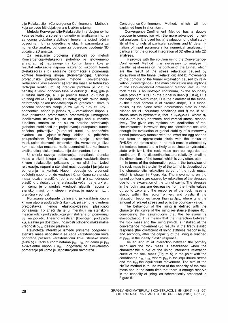
GRAĐEVINSKI MATERIJALI I KONSTRUKCIJE 58 (2015) 4 (21-36) BUILDING MATERIALS AND STRUCTURES 58 (2015) 4 (21-36)
26
cije-Relaksacije (Convergence-Confinement Method),koja će ovde biti objašnjena u kratkim crtama.
Metoda Konvergencije-Relaksacije ima dvojnu svrhukada se koristi u sprezi s numeričkim analizama i to: a)za ocenu globalne stabilnosti tunela na pojedinačnimodsecima i b) za određivanje ulaznih parametara zanumeričke analize, odnosno za posredno uvođenje 3Duticaja u 2D analizu.
Za rešavanje problema stabilnosti po metodiKonvergencija-Relaksacija potrebno je istovremenoanalizirati: a) naprezanje na konturi tunela koje jerezultat relaksacije napona izazvanog iskopom tunela(Relaksacija) i b) radijalne deformacije i pomeranjakonture tunelskog iskopa (Konvergencija). Osnovneproračunske pretpostavke metode Konvergencija-Relaksacija jesu sledeće: a) stenska masa se tretira kaoizotropni kontinuum; b) granični problem je 2D; c)nadsloj je visok, odnosno tunel je dubok (H/D>4), gde jeH visina nadsloja, a D je prečnik tunela; d) tunel jekružnog oblika (R je radijus tunela); e) važi ravno stanjedeformacija nakon uspostavljanja 2D graničnih uslova; f)početno naponsko stanje je za k0= σh / σv =1; (σh –horizontalni napon je jednak σv – vertikalnom naponu).Iako prikazane pretpostavke predstavljaju umnogomeidealizovane uslove koji se ne mogu naći u realnim tunelima, smatra se da su za potrebe određivanjaglobalne stabilnosti pri projektovanju autoputnih tunelanačelno prihvatljive (autoputni tuneli s podnožnimsvodom su jajasto-kružnog oblika s približnimpoluprečnikom R=5,5m; naponsko stanje u stenskojmasi, usled delovanja tektonskih sila, verovatno je blizuk0=1; stenska masa se može posmatrati kao kontinuumukoliko uticaj diskontinuiteta nije dominantan, i dr.).
U smislu razvoja deformacija, ponašanje stenskemase u blizini iskopa tunela, opisano karakterističnomkrivom relaksacije, prikazano je na slici 4.a. Usledrelaksacije, naponi u stenskoj masi opadaju i javljaju sepomeranja na konturi. Naponi opadaju od vrednostipočetnih napona σo do vrednosti 0, pri čemu se stenskamasa odziva elastično do vrednosti pi ≥ pcr odnosnoplastično u slučaju da je relaksacija veća i da je pi < pcr, pri čemu je p srednja vrednost glavnih napona ustenskoj masi, pi - stepen relaksacije napona i pcr -granična vrednost.
Ponašanje podgrade definisano je karakterističnom krivom otpora podgrade (slika 4.b), pri čemu je uvedenapretpostavka njenog elastično-idealno plastičnogponašanja. To znači da je u interakciji sa stenskommasom odziv podgrade, koja je instalirana pri pomeranjuuin, na početku linearno elastičan (koeficijent podgradeks), a zatim pri dostizanju nosivosti odnosno maksimalnevrednosti pmax idealno plastičan.
Ravnoteža interakcije između primarne podgrade istenske mase uspostavlja se kada karakteristična krivapodgrade preseče karakterističnu krivu stenske mase (slika 5) u tački s koordinatama peq, ueq, pri čemu je peqekvivalentni napon i ueq - odgovarajuće ekvivalentnopomeranje pri kome je uspostavljena ravnoteža.
Convergence-Confinement Method, which will be explained here in short form.
Convergence-Confinement Method has a double purpose in connection with the more advanced numeri-cal analyses. It is used for: a) evaluation of global stabi-lity of the tunnels at particular sections and b) determi-nation of input parameters for numerical analyses, in particular for the gradual integration of 3D effects into 2D analyses.
To provide with the solution using the Convergence-Confinement Method it is necessary to analyse in parallel: a) stresses on the contour of the tunnel, which are the result of the stress relaxation caused by excavation of the tunnel (Relaxation) and b) movements of the contour of the tunnel excavation caused by rela-xation (Convergence). The main calculation assumptions of the Convergence-Confinement Method are: a) the rock mass is an isotropic continuum, b) the boundary value problem is 2D, c) the tunnel is deep (H/D>4), H is the height of overburden, D is the diameter of the tunnel d) the tunnel contour is of circular shape, R is tunnel radius, e) the plane strain deformation state is esta-blished for 2D boundary conditions and f) the in situ stress state is hydrostatic, that is k0=σh/σv=1, where σh and σv are in sity horizontal and vertical stress, respec-tively. The given assumptions are idealisation of real circumstances. However, they are considered accurate enough for evaluation of global stability of a motorway tunnel (motorway tunnels with the invert are egg shaped but close to approximate circle with the radius of R=5,5m: the stress state in the rock mass is affected by the tectonic forces and is likely to be close to hydrostatic state with k0=1, the rock mass can be regarded as continuum, if the discontinuities are relatively small to the dimensions of the tunnel, which is very often, etc)
In terms of the deformation pattern the behaviour of the rock mass in the vicinity of the tunnel is described by the characteristic relaxation curve of the rock mass, which is shown in Figure 4a. The movements on the tunnel contour u are caused by relaxation of the stresses due to the excavation of the tunnel cavity. The stresses in the rock mass are decreasing from the in-situ values σo up to zero and the response of the rock mass is elastic within the region pi >pcr and plastic if the relaxation becomes larger than pi ≤pcr, where pi is the amount of relaxed stress and pcr is the boundary value.
The behaviour of the lining is defined with the characteristic curve of the lining resistance (Figure 4b), considering the assumptions that the behaviour is elastic-plastic. This means that the interaction between the rock mass and the lining (which is installed at the convergence movement uin) results in the firstly elastic response (the coefficient of lining stiffness response ks) and secondly, after the capacity of the lining is reached at pmax, in the ideally plastic response.
The equilibrium of interaction between the primary lining and the rock mass is established when the characteristic curve of the lining intersects relaxation curve of the rock mass (Figure 5) in the point with the coordinates peq, ueq, where peq is the equilibrium stress and the ueq the equilibrium movement. The aim of the NATM method is to use most of the capacity of the rock mass and in the same time that there is enough reserve in the capacity of lining, as schematically presented in Figure 5.

GRAĐEVINSKI MATERIJALI I KONSTRUKCIJE 58 (2015) 4 (21-36) BUILDING MATERIALS AND STRUCTURES 58 (2015) 4 (21-36)
27
a) b)
Slika 4. Karakteristična krive odziva: a) stenske mase i b) podgrade na iskop tunela Figure 4. Characteristic curves of: a) rock mass and b) tunnel support response to tunnel excavation
Slika 5. Tačka preseka krive stenske mase i krive otpora podgrade
Figure 5. Point of intersection for curves of rock mass and tunnel support
U smislu iskorišćenja nosivosti stenske mase, odključnog značaja je dostizanje tačke ravnotežnog stanja,što je posledica interakcije stenske mase i primarnepodgrade. U slučaju da se podgrada ugradi prekasno,može doći do tako velikih deformacija da se progresivnilom stenske mase ne može više sprečiti. Takođe, akonosivost podgrade nije zadovoljavajuća, podgrada možedostići granicu izdržljivosti pre dostizanja ravnoteže. Uoba slučaja, podgradna konstrukcija neće imati efekta,jer nije uspostavljeno ravnotežno stanje, te dolazi dorušenja u tunelu.
Trenutak postavljanja podgrade određuje se naosnovu uslova stabilnosti nepodgrađene stenske mase itehnološkog ograničenja deformacije konture, s ciljem dane dođe do nastanka potprofila. Inženjerski gledano,stanje konačne ravnoteže mora imati određeni faktorsigurnosti - kako u odnosu na nosivost podgrade, tako iu odnosu na nosivost stenske mase.
In the terms of utilisation of the capacity of rock mass it is of key importance to achieve equilibrium on the optimal place, as a result of preferred interaction of the rock mass and the lining. If the lining is installed too late for a given schedule of excavation (i.e. too far from the head of excavation), there would be too much deformation of the rock mass and the progressive failure might occur. Also, if the lining is of insufficient capacity, it can collapse before the equilibrium point is ever reached. In both cases the supporting structure is without effect, as equilibrium will not reached and the failure of the rock mass can occur.
The moment of the installation of the tunnel lining and the supporting elements is defined on the conditions of the stability of the unsupported tunnel and the technological limit of the amount of deformation for the tunnel contours so that the under-profile does not occur. From the engineering point of view, the state of the final equilibrium should have a certain factor of safety in terms of both the lining and the rock mass capacity.

GRAĐEVINSKI MATERIJALI I KONSTRUKCIJE 58 (2015) 4 (21-36) BUILDING MATERIALS AND STRUCTURES 58 (2015) 4 (21-36)
28
Dinamika gradnje: prelazak iz 3D graničnih uslova na 2D granične uslove
Cilj postupka metode Konvergencija-Relaksacijajeste određivanje uslova za pravovremenu ugradnjuprimarne podgrade koja ima zahtevanu nosivost, tako dase dostigne ravnoteža i s time zahtevana stabilnosttunela. Pritom, treba uzeti u obzir da inicijalni pomakstenske mase (uin), u trenutku postavljanja podgrade,zavisi od stepena relaksacije stene (λ), koji je u funkciji transfera s 3D graničnih uslova na 2D granične usloveravne deformacije. To je direktno povezano saudaljenošću nepodgrađenog dela tunela od čela iskopatunela. Pri gradnji tunela taj razmak manifestuje se kaokorak u tehnološkoj sekvenci iskopa i primarnogpodupiranja tunela.
Panet i Guénot (1982) modelirali su transfer s 3Dgraničnih uslova na 2D granične uslove ravnedeformacije uvodeći fiktivni pritisak σr
f koji deluje unutartunela. Vrednost fiktivnog pritiska određena je izinicijalnog napona σr
o koristeći izraz:
Schedule of construction: the transition from 3D to 2D boundary conditions
The aim of the application of Convergence-Confinement Method is the determination of the conditions for timely installation of the primary lining of required capacity, so that the equilibrium can be achieved and with this the required stability of tunnel excavation. In this sense it should be taken into account that the initial movement (uin) depends on the degree of the relaxation of the rock mass (λ). The degree of the relaxation of the rock mass (λ) is the function of transfer from the 3D boundary conditions to the 2D boundary conditions of plane strain, that is, the function of distance from supported part of the tunnel to the advancing head of excavation. This is seen in the technological sequence of tunnel construction as the one step of excavation and the primary support of the tunnel.
Panet and Guénot (1982) modelled the transfer from 3D to 2D boundary conditions by introducing the fictive supporting stress σr
f (Figure 6) acting within the tunnel cavity. The value of the fictive supporting stress is derived from the initial stress σr
o using the relationships:
( )1f o
r rσ λ σ= − ⋅ (1)
( )1 1o
o
p p pp
λ λ= − ⇒ = −
(2)
U gornjem izrazu, λ predstavlja koeficijent redukcije
napona kojim uvodimo 3D efekte čela iskopa u 2Dmodel proračuna tunela. Na određenoj udaljenosti ispredčela iskopa je λ=0 (uslovi su potpuno 3D, σr
f = σro,
odnosno p=p0), dok se ta vrednost povećava sve do λ=1 (uslovi su potpuno 2D, σr
f = 0 odnosno p=0) na rastojanju od približno dva do tri prečnika tunela iza čelaiskopa (slika 6).
in which λ is the coefficient of stress reduction. At a certain distance in front of the head of excavation λ=0 (the conditions are fully 3D, σr
f = σro, that is p=p0), and
this value increases up to λ =1 (the conditions are fully 2D, σr
f = 0, that is p=0). The 2D conditions are realised at the distance that is approximately 2 to 3 times the diameter D of the tunnel.
Slika 6. Model prelaza sa 3D graničnih uslova na 2D granične uslove ravne deformacije (Kavvadas 2004) Figure 6. Model of transition from 3D boundary conditions to 2D plain strain boundary conditions (Kavvadas, 2004)
Uvođenje prelaza s 3D graničnih uslova na 2Dgranične uslove stanja ravne deformacije u samom
The introduction of the transfer from 3D to 2D boundary conditions is done in three steps: (1)
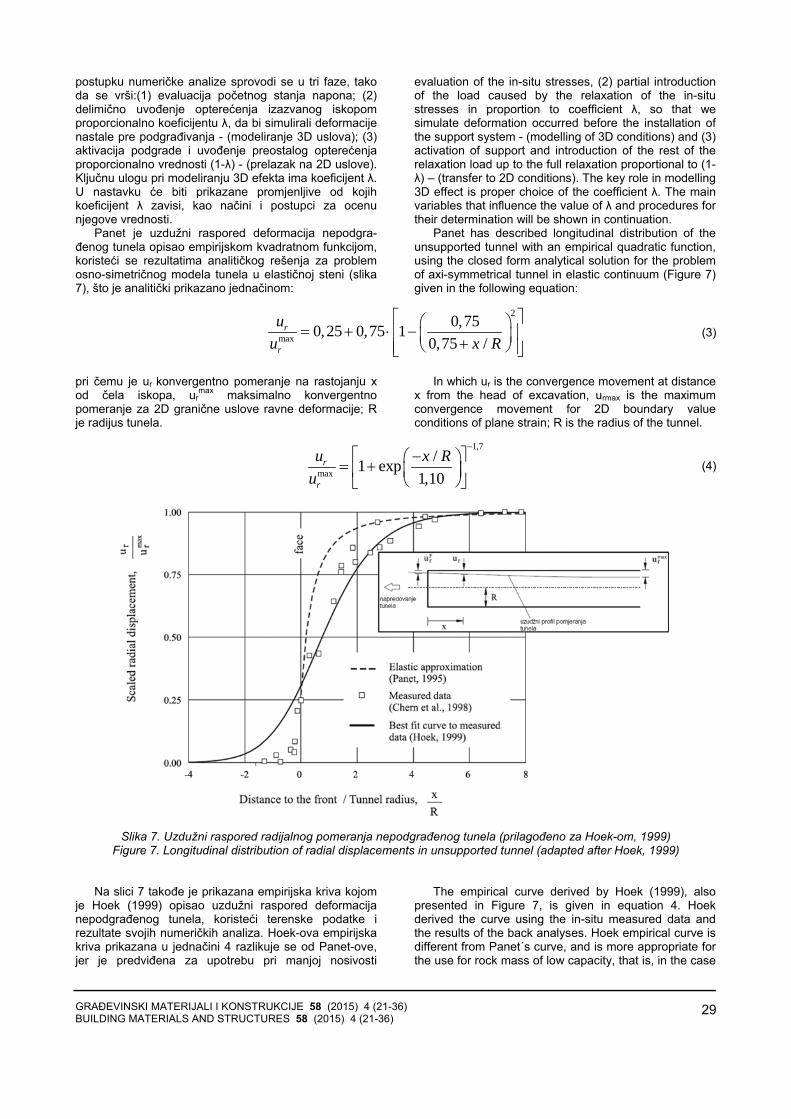
GRAĐEVINSKI MATERIJALI I KONSTRUKCIJE 58 (2015) 4 (21-36) BUILDING MATERIALS AND STRUCTURES 58 (2015) 4 (21-36)
29
postupku numeričke analize sprovodi se u tri faze, takoda se vrši:(1) evaluacija početnog stanja napona; (2)delimično uvođenje opterećenja izazvanog iskopomproporcionalno koeficijentu λ, da bi simulirali deformacijenastale pre podgrađivanja - (modeliranje 3D uslova); (3)aktivacija podgrade i uvođenje preostalog opterećenjaproporcionalno vrednosti (1-λ) - (prelazak na 2D uslove).Ključnu ulogu pri modeliranju 3D efekta ima koeficijent λ. U nastavku će biti prikazane promjenljive od kojihkoeficijent λ zavisi, kao načini i postupci za ocenu njegove vrednosti.
Panet je uzdužni raspored deformacija nepodgra-đenog tunela opisao empirijskom kvadratnom funkcijom,koristeći se rezultatima analitičkog rešenja za problemosno-simetričnog modela tunela u elastičnoj steni (slika 7), što je analitički prikazano jednačinom:
evaluation of the in-situ stresses, (2) partial introduction of the load caused by the relaxation of the in-situ stresses in proportion to coefficient λ, so that we simulate deformation occurred before the installation of the support system - (modelling of 3D conditions) and (3) activation of support and introduction of the rest of the relaxation load up to the full relaxation proportional to (1-λ) – (transfer to 2D conditions). The key role in modelling 3D effect is proper choice of the coefficient λ. The main variables that influence the value of λ and procedures for their determination will be shown in continuation.
Panet has described longitudinal distribution of the unsupported tunnel with an empirical quadratic function, using the closed form analytical solution for the problem of axi-symmetrical tunnel in elastic continuum (Figure 7) given in the following equation:
2
max
0,750,25 0,75 10,75 /
r
r
uu x R
⎡ ⎤⎛ ⎞= + ⋅ −⎢ ⎥⎜ ⎟+⎝ ⎠⎢ ⎥⎣ ⎦
(3)
pri čemu je ur konvergentno pomeranje na rastojanju xod čela iskopa, ur
max maksimalno konvergentnopomeranje za 2D granične uslove ravne deformacije; Rje radijus tunela.
In which ur is the convergence movement at distance x from the head of excavation, urmax is the maximum convergence movement for 2D boundary value conditions of plane strain; R is the radius of the tunnel.
1,7
max
/1 exp1,10
r
r
u x Ru
−⎡ ⎤−⎛ ⎞= + ⎜ ⎟⎢ ⎥
⎝ ⎠⎣ ⎦
(4)
Slika 7. Uzdužni raspored radijalnog pomeranja nepodgrađenog tunela (prilagođeno za Hoek-om, 1999)
Figure 7. Longitudinal distribution of radial displacements in unsupported tunnel (adapted after Hoek, 1999)
Na slici 7 takođe je prikazana empirijska kriva kojomje Hoek (1999) opisao uzdužni raspored deformacijanepodgrađenog tunela, koristeći terenske podatke irezultate svojih numeričkih analiza. Hoek-ova empirijska kriva prikazana u jednačini 4 razlikuje se od Panet-ove, jer je predviđena za upotrebu pri manjoj nosivosti
The empirical curve derived by Hoek (1999), also presented in Figure 7, is given in equation 4. Hoek derived the curve using the in-situ measured data and the results of the back analyses. Hoek empirical curve is different from Panet´s curve, and is more appropriate for the use for rock mass of low capacity, that is, in the case
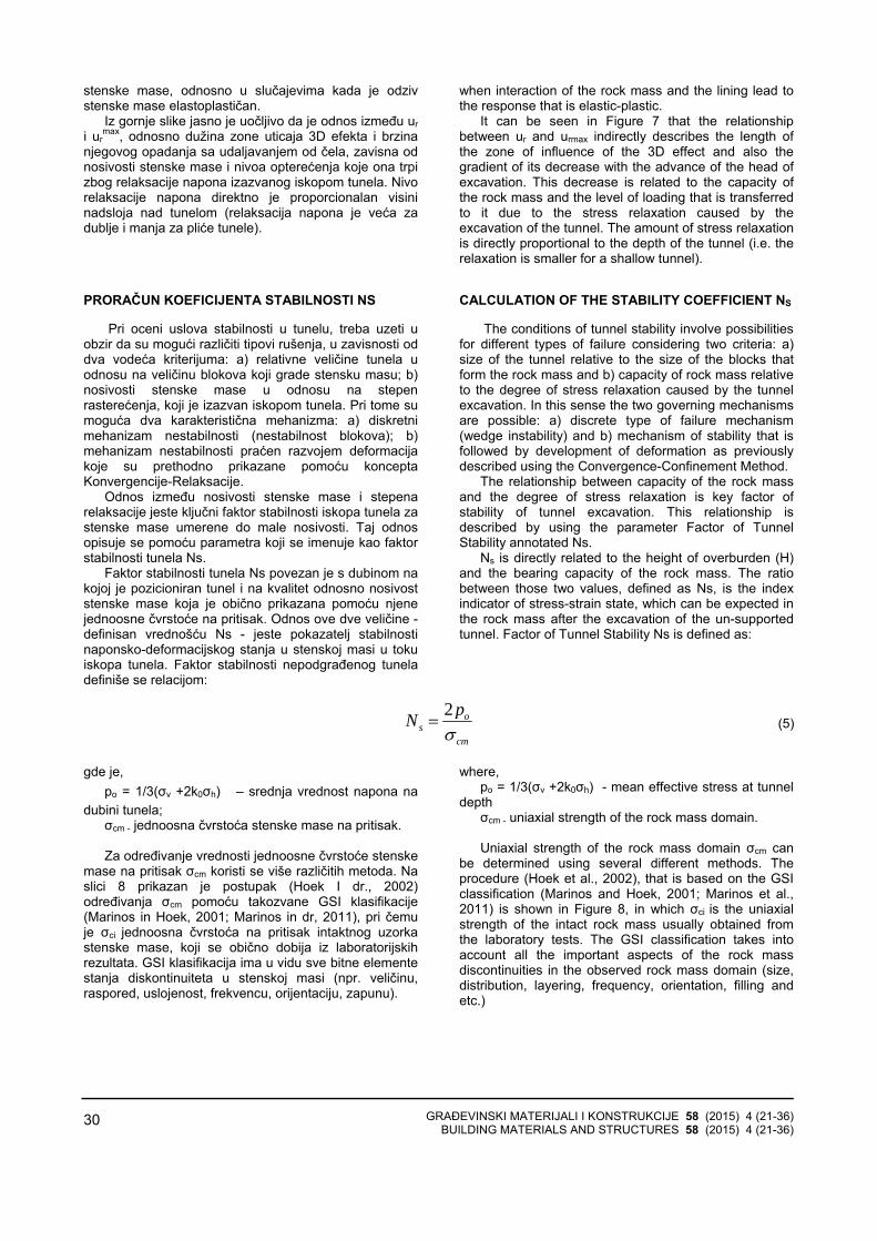
GRAĐEVINSKI MATERIJALI I KONSTRUKCIJE 58 (2015) 4 (21-36) BUILDING MATERIALS AND STRUCTURES 58 (2015) 4 (21-36)
30
stenske mase, odnosno u slučajevima kada je odzivstenske mase elastoplastičan.
Iz gornje slike jasno je uočljivo da je odnos između uri ur
max, odnosno dužina zone uticaja 3D efekta i brzinanjegovog opadanja sa udaljavanjem od čela, zavisna odnosivosti stenske mase i nivoa opterećenja koje ona trpizbog relaksacije napona izazvanog iskopom tunela. Nivorelaksacije napona direktno je proporcionalan visininadsloja nad tunelom (relaksacija napona je veća zadublje i manja za pliće tunele).
PRORAČUN KOEFICIJENTA STABILNOSTI NS
Pri oceni uslova stabilnosti u tunelu, treba uzeti uobzir da su mogući različiti tipovi rušenja, u zavisnosti oddva vodeća kriterijuma: a) relativne veličine tunela uodnosu na veličinu blokova koji grade stensku masu; b)nosivosti stenske mase u odnosu na stepenrasterećenja, koji je izazvan iskopom tunela. Pri tome sumoguća dva karakteristična mehanizma: a) diskretni mehanizam nestabilnosti (nestabilnost blokova); b)mehanizam nestabilnosti praćen razvojem deformacijakoje su prethodno prikazane pomoću konceptaKonvergencije-Relaksacije.
Odnos između nosivosti stenske mase i stepenarelaksacije jeste ključni faktor stabilnosti iskopa tunela zastenske mase umerene do male nosivosti. Taj odnosopisuje se pomoću parametra koji se imenuje kao faktorstabilnosti tunela Ns.
Faktor stabilnosti tunela Ns povezan je s dubinom nakojoj je pozicioniran tunel i na kvalitet odnosno nosivoststenske mase koja je obično prikazana pomoću njenejednoosne čvrstoće na pritisak. Odnos ove dve veličine -definisan vrednošću Ns - jeste pokazatelj stabilnostinaponsko-deformacijskog stanja u stenskoj masi u tokuiskopa tunela. Faktor stabilnosti nepodgrađenog tuneladefiniše se relacijom:
when interaction of the rock mass and the lining lead to the response that is elastic-plastic.
It can be seen in Figure 7 that the relationship between ur and urmax indirectly describes the length of the zone of influence of the 3D effect and also the gradient of its decrease with the advance of the head of excavation. This decrease is related to the capacity of the rock mass and the level of loading that is transferred to it due to the stress relaxation caused by the excavation of the tunnel. The amount of stress relaxation is directly proportional to the depth of the tunnel (i.e. the relaxation is smaller for a shallow tunnel).
CALCULATION OF THE STABILITY COEFFICIENT NS
The conditions of tunnel stability involve possibilities for different types of failure considering two criteria: a) size of the tunnel relative to the size of the blocks that form the rock mass and b) capacity of rock mass relative to the degree of stress relaxation caused by the tunnel excavation. In this sense the two governing mechanisms are possible: a) discrete type of failure mechanism (wedge instability) and b) mechanism of stability that is followed by development of deformation as previously described using the Convergence-Confinement Method.
The relationship between capacity of the rock mass and the degree of stress relaxation is key factor of stability of tunnel excavation. This relationship is described by using the parameter Factor of Tunnel Stability annotated Ns.
Ns is directly related to the height of overburden (H) and the bearing capacity of the rock mass. The ratio between those two values, defined as Ns, is the index indicator of stress-strain state, which can be expected in the rock mass after the excavation of the un-supported tunnel. Factor of Tunnel Stability Ns is defined as:
2 os
cm
pNσ
=
(5)
gde je,
po = 1/3(σv +2k0σh) ‒ srednja vrednost napona nadubini tunela;
σcm - jednoosna čvrstoća stenske mase na pritisak. Za određivanje vrednosti jednoosne čvrstoće stenske
mase na pritisak σcm koristi se više različitih metoda. Naslici 8 prikazan je postupak (Hoek I dr., 2002)određivanja σcm pomoću takozvane GSI klasifikacije(Marinos in Hoek, 2001; Marinos in dr, 2011), pri čemuje σci jednoosna čvrstoća na pritisak intaktnog uzorkastenske mase, koji se obično dobija iz laboratorijskihrezultata. GSI klasifikacija ima u vidu sve bitne elementestanja diskontinuiteta u stenskoj masi (npr. veličinu,raspored, uslojenost, frekvencu, orijentaciju, zapunu).
where, po = 1/3(σv +2k0σh) - mean effective stress at tunnel
depth σcm - uniaxial strength of the rock mass domain. Uniaxial strength of the rock mass domain σcm can
be determined using several different methods. The procedure (Hoek et al., 2002), that is based on the GSI classification (Marinos and Hoek, 2001; Marinos et al., 2011) is shown in Figure 8, in which σci is the uniaxial strength of the intact rock mass usually obtained from the laboratory tests. The GSI classification takes into account all the important aspects of the rock mass discontinuities in the observed rock mass domain (size, distribution, layering, frequency, orientation, filling and etc.)
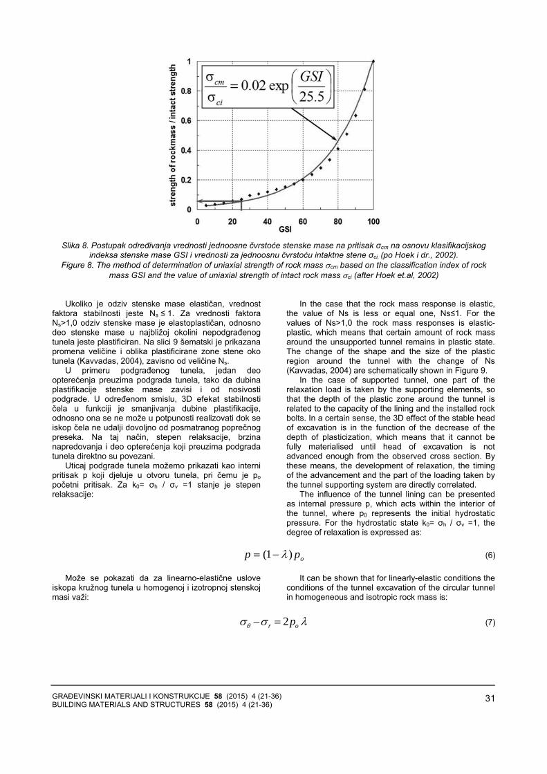
GRAĐEVINSKI MATERIJALI I KONSTRUKCIJE 58 (2015) 4 (21-36) BUILDING MATERIALS AND STRUCTURES 58 (2015) 4 (21-36)
31
Slika 8. Postupak određivanja vrednosti jednoosne čvrstoće stenske mase na pritisak σcm na osnovu klasifikacijskog
indeksa stenske mase GSI i vrednosti za jednoosnu čvrstoću intaktne stene σci, (po Hoek i dr., 2002). Figure 8. The method of determination of uniaxial strength of rock mass σcm based on the classification index of rock
mass GSI and the value of uniaxial strength of intact rock mass σci (after Hoek et.al, 2002)
Ukoliko je odziv stenske mase elastičan, vrednostfaktora stabilnosti jeste Ns ≤ 1. Za vrednosti faktora Ns>1,0 odziv stenske mase je elastoplastičan, odnosnodeo stenske mase u najbližoj okolini nepodgrađenogtunela jeste plastificiran. Na slici 9 šematski je prikazana promena veličine i oblika plastificirane zone stene okotunela (Kavvadas, 2004), zavisno od veličine Ns.
U primeru podgrađenog tunela, jedan deoopterećenja preuzima podgrada tunela, tako da dubinaplastifikacije stenske mase zavisi i od nosivostipodgrade. U određenom smislu, 3D efekat stabilnostičela u funkciji je smanjivanja dubine plastifikacije,odnosno ona se ne može u potpunosti realizovati dok seiskop čela ne udalji dovoljno od posmatranog poprečnogpreseka. Na taj način, stepen relaksacije, brzinanapredovanja i deo opterećenja koji preuzima podgradatunela direktno su povezani.
Uticaj podgrade tunela možemo prikazati kao internipritisak p koji djeluje u otvoru tunela, pri čemu je po početni pritisak. Za k0= σh / σv =1 stanje je stepenrelaksacije:
In the case that the rock mass response is elastic, the value of Ns is less or equal one, Ns≤1. For the values of Ns>1,0 the rock mass responses is elastic-plastic, which means that certain amount of rock mass around the unsupported tunnel remains in plastic state. The change of the shape and the size of the plastic region around the tunnel with the change of Ns (Kavvadas, 2004) are schematically shown in Figure 9.
In the case of supported tunnel, one part of the relaxation load is taken by the supporting elements, so that the depth of the plastic zone around the tunnel is related to the capacity of the lining and the installed rock bolts. In a certain sense, the 3D effect of the stable head of excavation is in the function of the decrease of the depth of plasticization, which means that it cannot be fully materialised until head of excavation is not advanced enough from the observed cross section. By these means, the development of relaxation, the timing of the advancement and the part of the loading taken by the tunnel supporting system are directly correlated.
The influence of the tunnel lining can be presented as internal pressure p, which acts within the interior of the tunnel, where p0 represents the initial hydrostatic pressure. For the hydrostatic state k0= σh / σv =1, the degree of relaxation is expressed as:
opp )1( λ−=
(6) Može se pokazati da za linearno-elastične uslove
iskopa kružnog tunela u homogenoj i izotropnoj stenskojmasi važi:
It can be shown that for linearly-elastic conditions the conditions of the tunnel excavation of the circular tunnel in homogeneous and isotropic rock mass is:
λσσθ or p2=−
(7)
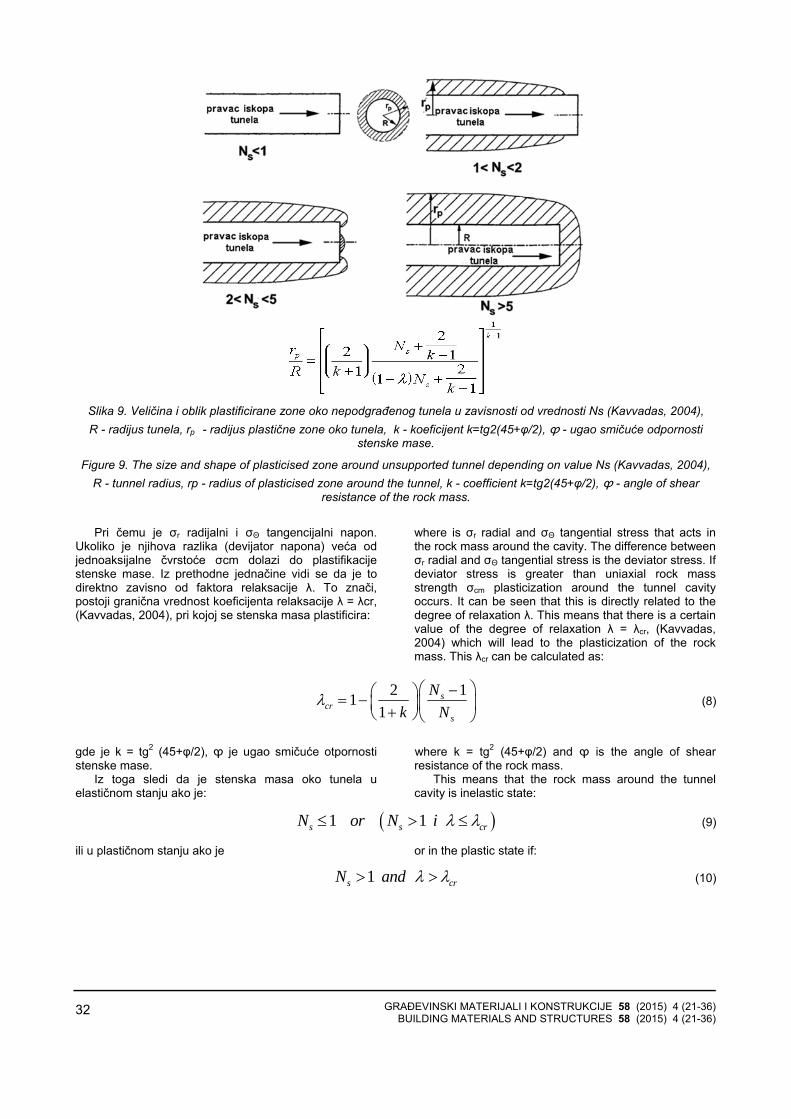
GRAĐEVINSKI MATERIJALI I KONSTRUKCIJE 58 (2015) 4 (21-36) BUILDING MATERIALS AND STRUCTURES 58 (2015) 4 (21-36)
32
Slika 9. Veličina i oblik plastificirane zone oko nepodgrađenog tunela u zavisnosti od vrednosti Ns (Kavvadas, 2004), R - radijus tunela, rp - radijus plastične zone oko tunela, k - koeficijent k=tg2(45+φ/2), ϕ - ugao smičuće odpornosti
stenske mase.
Figure 9. The size and shape of plasticised zone around unsupported tunnel depending on value Ns (Kavvadas, 2004), R - tunnel radius, rp - radius of plasticised zone around the tunnel, k - coefficient k=tg2(45+φ/2), ϕ - angle of shear
resistance of the rock mass.
Pri čemu je σr radijalni i σΘ tangencijalni napon.
Ukoliko je njihova razlika (devijator napona) veća odjednoaksijalne čvrstoće σcm dolazi do plastifikacijestenske mase. Iz prethodne jednačine vidi se da je todirektno zavisno od faktora relaksacije λ. To znači, postoji granična vrednost koeficijenta relaksacije λ = λcr, (Kavvadas, 2004), pri kojoj se stenska masa plastificira:
where is σr radial and σΘ tangential stress that acts in the rock mass around the cavity. The difference between σr radial and σΘ tangential stress is the deviator stress. If deviator stress is greater than uniaxial rock mass strength σcm plasticization around the tunnel cavity occurs. It can be seen that this is directly related to the degree of relaxation λ. This means that there is a certain value of the degree of relaxation λ = λcr, (Kavvadas, 2004) which will lead to the plasticization of the rock mass. This λcr can be calculated as:
2 111
scr
s
Nk N
λ⎛ ⎞−⎛ ⎞= − ⎜ ⎟⎜ ⎟+⎝ ⎠⎝ ⎠
(8)
gde je k = tg2 (45+φ/2), ϕ je ugao smičuće otpornostistenske mase.
Iz toga sledi da je stenska masa oko tunela uelastičnom stanju ako je:
where k = tg2 (45+φ/2) and ϕ is the angle of shear resistance of the rock mass.
This means that the rock mass around the tunnel cavity is inelastic state:
( )1 1s s crN or N i λ λ≤ > ≤ (9)
ili u plastičnom stanju ako je or in the plastic state if:
1s crN and λ λ> > (10)
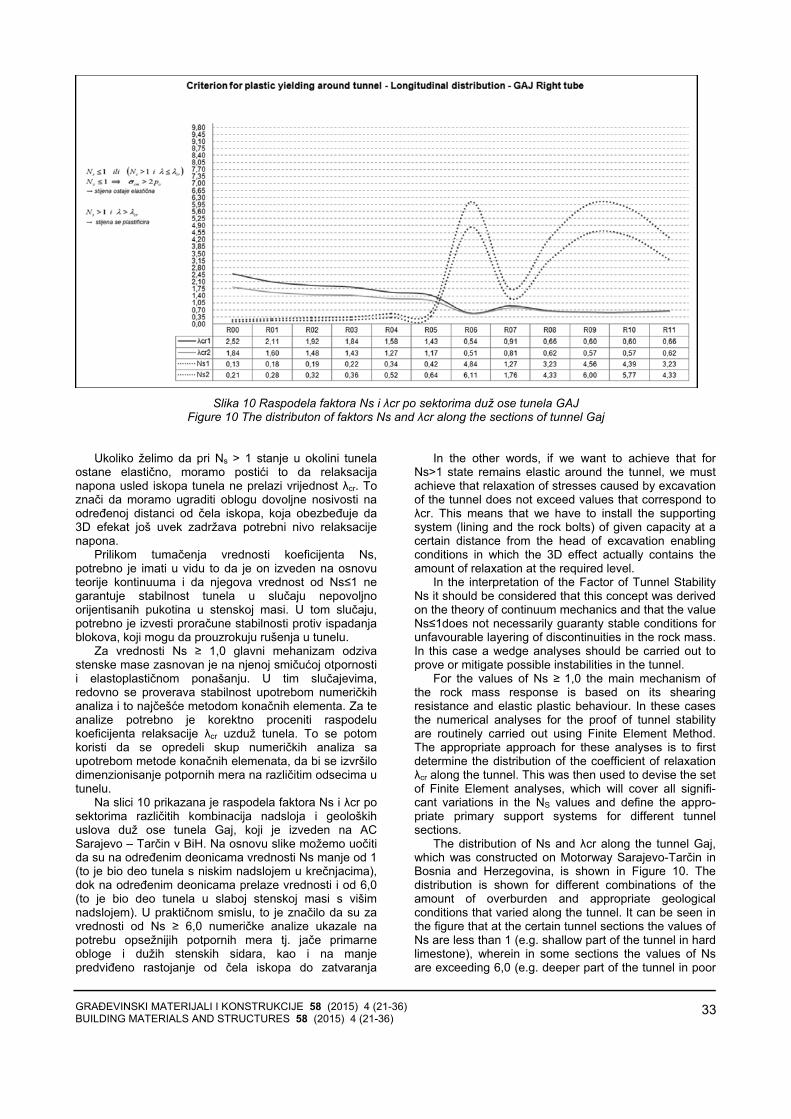
GRAĐEVINSKI MATERIJALI I KONSTRUKCIJE 58 (2015) 4 (21-36) BUILDING MATERIALS AND STRUCTURES 58 (2015) 4 (21-36)
33
Slika 10 Raspodela faktora Ns i λcr po sektorima duž ose tunela GAJ
Figure 10 The distributon of faktors Ns and λcr along the sections of tunnel Gaj Ukoliko želimo da pri Ns > 1 stanje u okolini tunela
ostane elastično, moramo postići to da relaksacijanapona usled iskopa tunela ne prelazi vrijednost λcr. To znači da moramo ugraditi oblogu dovoljne nosivosti naodređenoj distanci od čela iskopa, koja obezbeđuje da3D efekat još uvek zadržava potrebni nivo relaksacijenapona.
Prilikom tumačenja vrednosti koeficijenta Ns,potrebno je imati u vidu to da je on izveden na osnovuteorije kontinuuma i da njegova vrednost od Ns≤1 ne garantuje stabilnost tunela u slučaju nepovoljnoorijentisanih pukotina u stenskoj masi. U tom slučaju,potrebno je izvesti proračune stabilnosti protiv ispadanjablokova, koji mogu da prouzrokuju rušenja u tunelu.
Za vrednosti Ns ≥ 1,0 glavni mehanizam odzivastenske mase zasnovan je na njenoj smičućoj otpornostii elastoplastičnom ponašanju. U tim slučajevima,redovno se proverava stabilnost upotrebom numeričkihanaliza i to najčešće metodom konačnih elementa. Za teanalize potrebno je korektno proceniti raspodelukoeficijenta relaksacije λcr uzduž tunela. To se potomkoristi da se opredeli skup numeričkih analiza saupotrebom metode konačnih elemenata, da bi se izvršilodimenzionisanje potpornih mera na različitim odsecima utunelu.
Na slici 10 prikazana je raspodela faktora Ns i λcr posektorima različitih kombinacija nadsloja i geološkihuslova duž ose tunela Gaj, koji je izveden na AC Sarajevo – Tarčin v BiH. Na osnovu slike možemo uočitida su na određenim deonicama vrednosti Ns manje od 1(to je bio deo tunela s niskim nadslojem u krečnjacima),dok na određenim deonicama prelaze vrednosti i od 6,0(to je bio deo tunela u slaboj stenskoj masi s višimnadslojem). U praktičnom smislu, to je značilo da su zavrednosti od Ns ≥ 6,0 numeričke analize ukazale napotrebu opsežnijih potpornih mera tj. jače primarneobloge i dužih stenskih sidara, kao i na manjepredviđeno rastojanje od čela iskopa do zatvaranja
In the other words, if we want to achieve that for Ns>1 state remains elastic around the tunnel, we must achieve that relaxation of stresses caused by excavation of the tunnel does not exceed values that correspond to λcr. This means that we have to install the supporting system (lining and the rock bolts) of given capacity at a certain distance from the head of excavation enabling conditions in which the 3D effect actually contains the amount of relaxation at the required level.
In the interpretation of the Factor of Tunnel Stability Ns it should be considered that this concept was derived on the theory of continuum mechanics and that the value Ns≤1does not necessarily guaranty stable conditions for unfavourable layering of discontinuities in the rock mass. In this case a wedge analyses should be carried out to prove or mitigate possible instabilities in the tunnel.
For the values of Ns ≥ 1,0 the main mechanism of the rock mass response is based on its shearing resistance and elastic plastic behaviour. In these cases the numerical analyses for the proof of tunnel stability are routinely carried out using Finite Element Method. The appropriate approach for these analyses is to first determine the distribution of the coefficient of relaxation λcr along the tunnel. This was then used to devise the set of Finite Element analyses, which will cover all signifi-cant variations in the NS values and define the appro-priate primary support systems for different tunnel sections.
The distribution of Ns and λcr along the tunnel Gaj, which was constructed on Motorway Sarajevo-Tarčin in Bosnia and Herzegovina, is shown in Figure 10. The distribution is shown for different combinations of the amount of overburden and appropriate geological conditions that varied along the tunnel. It can be seen in the figure that at the certain tunnel sections the values of Ns are less than 1 (e.g. shallow part of the tunnel in hard limestone), wherein in some sections the values of Ns are exceeding 6,0 (e.g. deeper part of the tunnel in poor
GRAĐEVINSKI MATERIJALI I KONSTRUKCIJE 58 (2015) 4 (21-36) BUILDING MATERIALS AND STRUCTURES 58 (2015) 4 (21-36)
34
podnožnog svoda. Na slici su prikazani proračuni Ns iλcr za različite vrednosti koeficijenta K0 i to za K0=1-sin ϕ i K0=1,0, što se smatralo logičnim graničnimvrednostima za koeficijent pritiska tla u stanju mirovanja.
ZAVRŠNE NAPOMENE I ZAKLJUČAK
U skladu s principima NATM, dozvoljen je - čak i poželjan - određeni nivo plastifikacije oko otvora tunela,ali on ne sme prekoračiti dužinu sidara. U idealnimokolnostima, plastifikacija ne prelazi dubinu od 3 m do maksimalno 6 m, što odgovаra približnoj vrednosti Ns=5-6. U slučajevima kada Ns prekorači vrednost 7, možemoočekivati teškoće pri gradnji tunela, jer je to približno igranica upotrebljivosti koncepta NATM.
Ako to dozvoljava nosivost stenske mase, pravilo je da treba težiti da njen odziv ostane pretežno elastičan.To garantuje dugoročnu trajnost tunela, odnosno manjuzavisnost njegove stabilnosti od materijala ugrađenih unjegovu podgradu. Ključno pitanje na koje projektantmora odgovoriti jeste na kojem rastojanju od čela iskopase javlja vrednost λcr i kakvu oblogu treba ugraditi na tommestu da bi odziv stenske mase bio pretežno elastičanodnosno plastičan do željenog nivoa.
U numeričkim analizama potrebno je težiti tome dase usvoji vrijednost λ koja je bliska vrednosti za λcr, jer to omogućava dimenzionisanje podgrade koja ćezadovoljiti potrebu dominantnog elastičnog odzivastenske mase. Ukoliko je vrednost faktora stabilnostitunela Ns<1,0, to implicira višu vrednost za λ jer stenskamasa ima zahtevanu nosivost, tako da samo mali deoopterećenja preuzima primarna podgrada. U skladu stim, unutrašnje sile u oblozi biće relativno male i obratno,manji λ-faktor znači veće unutrašnje sile i manjedeformacije stenske mase.
Vrednost λ-faktora - koja se koristi kao ulaznipodatak za numeričke analize - utvrđuje se na baziteorijskih pretpostavki i ocene nosivosti odnosnokvaliteta stenske mase. Svakako, najrealnija ocenavrednost λ-faktora i interakcije potpornog sistema istenske mase postiže se povratnim statičkim analizama.Za efikasnu primenu povratnih analiza potrebno jeobezbediti podatke na osnovu tekućeg praćenja svihvažnih pokazatelja interakcije stenske mase i potpornihelementa. U tu svrhu, u toku građenja tunela, potrebnoje kontinuirano: a) vršiti geološko kartiranje čela iskopa ivalorizaciju parametra čvrstoće stenske mase; b)dnevno meriti radijalne deformacije u tunelu; c) popotrebi, ugrađivati i interpretirati merne profile zaodređivanje pomeranja po dubini stenske mase istepena mobilizacije stenskih sidara. Merni profili (tj. ekstenzometri i merna sidra) po pravilu se koriste uslučaju pojave slabijih geoloških uslova. Na osnovudobijenih informacija pokazatelja stanja u tunelu irezultata povratnih analiza, projektant dobija mogućnostda pravilno odluči o eventualnoj promeni podgradnogsklopa radi optimizacije gradnje tunela.
Prethodna objašnjenje osnovnih pojmova principaNATM jesu osnova za uspešno, sigurno i ekonomskiopravdano građenja tunela. U praksi je to, nažalost,
rock). In the sections with the values of Ns ≥ 6,0 the numerical analyses were used to dimension the elaborate primary support including stronger primary lining, longer rock bolts and the requirement for the short distance from the head of excavation to the closing of the tunnel invert. The calculations of Ns and λcr in the figure are given for the different values of the coefficient of earth pressure at rest K0 for K0=1-sinϕ and K0=1,0, which are considered to be appropriate boundary values.
THE FINAL REMARKS AND CONCLUSIONS
In accordance to the principles of NATM, certain level of plasticization around the cavity of the tunnel is desirable, but its size must not exceed the length of the rock bolts. In the ideal circumstances the depth of plasticization around the tunnel should be kept around 3m and should not exceed 6m, which corresponds to the approximate value of Ns=5-6. In cases when NS exceeds the value of 7,0 one can expect difficulties during the tunnel construction, as this indicates practical limit for successful use of NATM.
As a rule (if the self-capacity of the rock mass allows for it) one should strive to keep the rock mass in predominantly elastic state as this complements to the durability of tunnel construction, that is, ensures less dependence on the materials installed in the tunnel (e.g tunnel lining and rock bolts). The key question that designer should answer is at what distance from the head of excavation is the value of λcr and what type of primary support at that position should be installed so that the response of the rock mass remains elastic or becomes plastic up to the desired level.
If possible, during the execution of the finite element analyses, the value of λ should be chosen to be close to λcr, as this will result into the dimension of the primary lining within the required elastic response of the rock mass. If the value of Factor of Tunnel Stability is Ns<1,0 this implies higher value for λ as the rock mass have the required capacity and only a small fraction of the relaxation is taken by the supporting system. The opposite is also true; the lower value of λ implies higher internal forces in the lining and less deformation of the rock mass.
The value of the coefficient λ, which is used as the input parameter for the numerical analyses, is deter-mined from the described theoretical concepts and the prediction of the rock mass quality. However, the most realistic determination of the factor λ and interaction between the supporting system and the rock mass isevaluated using the back analyses. For the efficient use of back analyses it is necessary to obtain all the relevant information with regard to the interaction of the rock mass and the tunnel lining. For this purpose a perma-nent monitoring of the key indicators is carried out during the tunnel construction: a) geological mapping of the head of excavation and evaluation of the quality of the rock mass, b) daily assessment of the convergence movement in the tunnel, and c) if necessary the instal-ment and interpretation of measuring profiles for deter-mination of the movements of the rock mass and the degree of mobilisation of rock bolts. The measuring profiles (e.g. extensometers and measuring anchors) are typically installed within the poor geological conditions. On the basis of the interpretation of the indicators of the

GRAĐEVINSKI MATERIJALI I KONSTRUKCIJE 58 (2015) 4 (21-36) BUILDING MATERIALS AND STRUCTURES 58 (2015) 4 (21-36)
35
veoma teško dostići, jer se kontinuirano praćenjegradnje tunela ne izvodi pravovremeno i kvalitetno. Toposledično onemogućava pravovremeno donošenjepravilnih odluka u smislu prilagođavanja primarnepodgrade u skladu s promenom uslova gradnje.
Sve pokazatelje uspešnosti gradnje u praksikontinuirano prati projektant u okviru projektantskognadzora. Projektantski nadzor obuhvata prikupljanjeinformacija o geološkim i hidrogeološkim uslovimagradnje, praćenje merenja radijalnih pomeranja nakonturi iskopa, praćenje rezultata drugih mernih profila, izvršenje povratnih analiza stabilnosti iskopa tunela ipravoremeno predlaganje promene podgradnog sistemaako je to potrebno.
Za uspešno delovanje projektantskog nadzoramoraju biti jasno određene obaveze i dužnosti svihaktera gradnje: izvođača, inženjera, investitora iprojektanta. Osnovni odnosi moraju biti definisanifleksibilnim tipom ugovora koji omogućava optimizacijugradnje i sprečava nepotrebno trošenje finansijskihsredstava, kao i materijalnih i ljudskih resursa. Iskustvo autora govori u prilog tome da se samo u tom slučajudobijaju zadovoljavajući rezultati i iskorišćavajupotencijali koje u sebi nosi pravilna upotreba metodeNATM. U suprotnom, gradnja tunela može bitinepotrebno skupa i neefikasna, s pogubnim finansijskim posledicama za investitora i izvođača. Postizanjefleksibilne ugovorne strukture koja je bazirana na crvenojknjizi FIDIC-a (naplaćivanje prema izvedenimkoličinama) po iskustvu projektanta jeste najprimerenijerešenje za aplikaciju principa NATM u tunelogradnji.
state in the tunnel and the results of the back analyses, the designer becomes able to achieve the correct deci-sions with regard to eventual change of the supporting system and thus optimisation of tunnel construction.
Understanding of the basic NATM principles presented in the paper is the basis for successful, safe and economically viable tunnel construction. Unfortunately, in practise, this is usually difficult to achieve as the permanent monitoring is not carried out on time and with required quality. In consequence, the well-timed and correct decisions are not taken and there is no appropriate change of primary support to conform the change in boundary conditions.
The permanent evaluation of indicators of tunnel construction should be carried out by the designer within the process of designer supervision. The designer supervision comprises the acquisition of geological and hydrogeological data, monitoring of the convergence movements on the excavation contour, monitoring and interpretation of the results of the measuring profiles, execution of the back analyses for the evaluation of tunnel stability and propositions for the change of supporting system when appropriate.
For a successful execution of the designer super-vision it is necessary that all the actors in construction: designer, contractor, engineer, and client have clearly defined roles. The relationships should be defend within the flexible contractual framework that enables the optimisation of construction and prevent unnecessary wasteful use of resources: human, material and financial. The experience of the authors is such that only under those circumstances there are satisfactory results and proper utilisation of the potential of NATM. Otherwise, the tunnel construction can be unnecessary expensive bringing up deadly financial consequences to the client and/or to the contractor. The establishment of flexible contractual framework within the red book of the FIDIC type of contract (admeasurement) is the most appropriate solution for application of NATM in practice by the experience of the authors.
LITERATURA LITERATURE [1] Hoek, E. 1999. Support for very weak rock
associated with faults and shear zonesDistinguished lecture for the opening of theInternational Symposium on Rock Support andReinforcement Practice in Mining, Kalgoorlie,Australia, 14-19 March, 1999.
[2] Hoek E. Carranza Torres, C. & Corkum, B. 2002. Hoek-Brown failure criterion – 2002 edition.Proceedings of the Fifth North American Rock Mechanics Symposium (NARMS-TAC) (Eds:Hammah, R., Bawden, W., Curran, J. & Telesnicki,M.), 1, 267-273. University of Toronto Press,Toronto.
[3] Golser J., 1976, The New Austrian TunnelingMethod (NATM), Theoretical Background &Practical Experiences. 2nd Shotcrete conference,Easton, Pennsylvania (USA), 4-8 Oct 1976.
[4] Jovičić, Vojkan, ŠUŠTERŠIČ, Jakob, VUKELIČ,Željko. The application of fibre reinforced shotcreteas primary support for a tunnel in flysch. Tunn.
undergr. space technol.. [Print ed.], 2009, vol. 24, no. 6, str. 723-730. [COBISS.SI-ID 946015] FA -construction & building technology ; 19/49
[5] Kavvadas, M. 2004. Design of Underground Structures. University Notes. Specialised Master Design and Construction of Underground Works. National Technical, University of Athens
[6] Marinos, P., Hoek, E. 2001. Estimating the geotechnical properties of heterogeneous rock masses of Flysch. Bull. Eng. Geol. Env., 60: 85–92.
[7] Marinos, V., Fortsakis, P., Prountzopouls, G. 2011. Estimation of geotechnical properties and classification of geotechnical behaviour in tunnelling for flysch rock masses. V: Proceedings of the 15th European Conference on Soil Mechanics and Geotechnical Engineering. IOS Press. pp. 435-440.
[8] Panet, M. and Guénot, A. 1982. Analysis of convergence behind face of a tunnel. In Proc. Tunnelling’82, pp. 197–203. IMM, London.

GRAĐEVINSKI MATERIJALI I KONSTRUKCIJE 58 (2015) 4 (21-36) BUILDING MATERIALS AND STRUCTURES 58 (2015) 4 (21-36)
36
REZIME
KORISNI KONCEPTI U PRIMENI NOVE AUSTRIJSKE METODE ZA GRADNJU TUNELA
Vojkan JOVIČIĆ Jasmin BUČO Nermin ŠEHAGIĆ Alaga HUSIĆ
U članku su predstavljeni koncepti razvijeni udugogodišnjoj praksi pri projektovanju i gradnji tunelaprimenom Nove austrijske metode (New AustrianTunnelling Method - NATM). Cilj članka jeste da predočiosnovne teorijske koncepte ove metode i da izneseiskustva kako pri projektovanju tunela, tako i pri aplikacijitih principa na konkretnim primerima. Prikazana suuputstva za primenu korisnih koncepta prilikomdimenzionisanja primarne podgrade, kao i metodologija ocene stepena upotrebljivosti NATM metode za date granične uslove. U članku su takođe obrađeni postupciprimene NATM metode u uslovima izvođenja radova, pričemu je kao osnova za uspešan rad ispostavljenaaktivna uloga projektanta i fleksibilnost ugovornihodnosa između investitora i izvođača.
Ključne reči: projektovanje, tuneli, NATM, SCL,stenska masa, nosivost
SUMMАRY
USEFUL CONCEPTS FOR APPLICATION OF NEW AUSTRIAN TUNNELLING METHOD IN TUNNEL CONSTRUCTION
Vojkan JOVICIC Jasmin BUCO Nermin SEHAGIC Alaga HUSIC
The concepts that where developed in the long-standing practice in designing and constructing tunnels using New Austrian Tunnelling Method (NATM) are presented in the paper. The aim of the paper is to highlight the basic theoretical concepts and to expose the experience in the design and the application of NATM principles following the concrete examples. The procedures used in the application of these principles are also addressed in the paper, in which the active role of the designer and the contractual flexibility between the contractor and the client are seen as the key conditions for a successful work.
Key words: design, tunnels, NATM, SCL, rock mass, capacity
GRAĐEVINSKI MATERIJALI I KONSTRUKCIJE 58 (2015) 4 (37-49) BUILDING MATERIALS AND STRUCTURES 58 (2015) 4 (37-49)
37
KRITERIJUM STABILNOSTI DEFORMACIJE ELASTOPLASTIČNIH MATERIJALA CONDITIONS FOR STABILITY OF DEFORMATION IN ELASTO-PLASTIC MATERIALS
Selimir V. LELOVIĆ ORIGINALNI NAUČNI RAD
ORIGINAL SCIENTIFIC PAPERUDK: 691.175
doi: 10.5937/grmk1504037L
UVOD
Problem stabilnosti geomehaničkih materijala zatačno utvrđenu geometriju, granične uslove i karakteropterećenja, zahteva određivanje intervala parametaraopterećenja, pri kojem naponsko-deformacijske veličineimaju konačne vrednosti. Gubitak stabilnosti može seposmatrati i kao početak loma materijala.
Od velikog praktičnog značaja jeste to da se odredida li će posmatrana plastična deformacija - u trenutkukada je dostignuto ravnotežno stanje - povećati svojudužinu za konačan (mali) inkrement i prestati s rastom(stabilan režim deformisanja) ili će nastaviti s nekontroli-sanim rastom dok ne dođe do velikih priraštaja posma-tranih deformacija (nestabilan režim deformisanja). Pre-laz fizičkog (mehaničkog) sistema iz stabilnog režimadeformisanja u nestabilan režim deformisanja često senaziva gubitak stabilnosti.
Granica ovog prelaza poznata je kao kritično stanjematerijala, a njemu odgovarajuće opterećenje jeste kriti-čno opterećenje. Potreban uslov za gubitak stabilnostiponašanja materijala, gubitak jedinstvenosti rešenja ipojavu bifurkacije jeste promena znaka drugog izvodafunkcije rada na plastičnom deformisanju materijala (Drucker, 1950). S jedne strane, Drucker-ov postulatpredviđa dovoljan uslov za stabilno ponašanje materija-la, određena teorijska razmatranja ukazuju na to da je ovo možda samo potreban, ali ne i dovoljan uslov (Mroz, 1964). Ponašanje materijala postaje nestabilno kadapočinje da se gubi eliptičnost tangente matrice krutosti.Ovaj početak nestabilnog ponašanja materijala povezan je s tačkom bifurkacije ili odstupanja od jedinstvenogrešenja na ravnotežnoj putanji (Mandel, 1964). Pojava
Selimir V. Lelović, Univerzitet u Beogradu Građevinski fakultet, Bulevar kralja Aleksandra br. 73, Beograd [email protected]
INTRODUCTION
Stability of deformation for a geomechanical material under applied load, for defined geometry and boundary conditions, requires determination of the load interval where stress-strain properties have definite values. Loss of material stability may be considered as initiation of material failure.
From the practical point of view it is important to determine for the small increment in stress, if the plastic deformation increment was small (stable deformation occurred) or large (unstable deformation occurred). Losing the stability of deformation occurred at the boundary between these two regimes. The loading condition at the boundary is called the critical loading while material is called to be in a critical state.
The term "stability" is used here as a quasi-static response of a material under small increments of displacements. Necessary condition for the stability loss, as well as loss in unique relationship and appearance of bifurcation is the sign change in the second derivative of the work function (Drucker, 1950). Although from one point of view, Drucker's postulate provides a sufficient condition for material stability, some theoretical con-siderations have suggested that this is only a necessary condition (Mroz, 1964). Material instability occurs when ellipticity of the tangent stiffness matrix is lost. The beginning of unstable material behavior is connected with bifurcation point or deviation from the unique solution on the equilibrium path (Mandel, 1964). The onset of localized deformation is often associated with the satisfaction of the classical discontinuous bifurca-tion criterion. The localized deformation phenomena in
Selimir V. Lelovic, University of Belgrade, Faculty of Civil Engineering, King Alexander Blvd., # 73, Belgrade [email protected]
GRAĐEVINSKI MATERIJALI I KONSTRUKCIJE 58 (2015) 4 (37-49) BUILDING MATERIALS AND STRUCTURES 58 (2015) 4 (37-49)
38
lokalizovane deformacije, u klasičnom smislu diskonti-nuiteta, obično je povezana s pojavom tačke bifurkacije. Fenomen lokalizacije deformacije u granularnim materi-jalima veoma je interesantan kako sa eksperimentalne,tako i sa analitičke tačke gledišta. Klasični rezultati zaelastoplastični kontinuum izraženi preko kritične vred-nosti modula ojačanja i odgovarajuća orijentacija trakeklizanja (shear band) prikazani su u radovima (Hill,1950), (Rudnicki i sar., 1975) i (Rice, 1976). U ovimradovima definisani su statički i kinematički uslovi započetak klizanja u granularnom materijalu. Matematičkiprecizan kriterijum za određivanje položaja kritične tačkeizveden iz generalnog razmatranja svojstvenih vrednostitangentne matrice krutosti (Borst, 1988). Ovako postav-ljen kriterijum za određivanje kritične tačke vrlo je pogo-dan sa stanovišta praktične primene. Više autora prime-nilo je ovu metodologiju na granularne materijale, s tim što su koristili Mohr-Coulomb-ov kriterijum kao funkciju tečenja.
U ovom radu prvo su prikazana generalna razmatra-nja odnosa napon-deformacija i kriterijum za određivanjekritične tačke deformacije, zatim tri ilustrativna primera,poređenje dobijenih rezultata sa eksperimentalnimvrednostima i naposletku - zaključak.
KONSTITUTIVNE JEDNAČINE
U teoriji plastičnosti obično se zanemaruju uticajibrzine deformacije i temperaturnog polja. Tako dobijenateorija zove se izotermička teorija plastičnosti.Ograničićemo naša razmatranja na izotermički process( . 0)= >T cons . Pomeranje tačke tela označićemo sa
( )u x , gde su sa x označene pravougle Dekartove koordinate posmatrane tačke. Usvajajući pretpostavku o malim pomeranjima, tenzor deformacije može senapisati u obliku:
granular material are very interesting not only from the experimental point of view but numerical as well. Now classical results for elasto-plastic continuum derived from the critical values for the hardening modulus and corresponding orientation of the so called shear band were published by (Hill, 1950), (Rudnicki and Rice., 1975) and (Rice, 1976).
Static and kinematic conditions for the onset of slip (shear band) in granular materials were presented in those papers. Mathematically precise criteria to deter-mine the critical point position is derived from general considerations of the values for the tangent of the material stiffness constants (Borst, 1988). Criteria established in such a way showed to be very useful for practical applications. Presented methodology was used by many authors, mostly employing the classical Mohr-Coulomb’s type yield function.
In this paper, general points about the stress-strain relationship and the critical point deformation are given first; second two illustrative examples are given along with published experimental results; third analysis of the compared differences in critical loads and at the end are given conclusions.
CONSTITUTIVE EQUATIONS
In theory of plasticity, rate of deformation and temperature effects are usually neglected. Such considerations are called isothermal plasticity. In this work considerations are restricted to isothermalprocesses ( . 0)= >T cons . The displacement of a point
in the body is characterized by ( )u x , where x are the rectangular Cartesian coordinates of the point. Following the assumption of small displacements, the strain-displacement relations are:
, ,2ε = +ij i j j iu u (1)
gde zarez označava parcijalni izvod po odgovarajućojkoordinati. Veza između napona i elastične deformacijeodređena je Hukovim zakonom. Funkcija plastičnogpotencijala za izotropan materijal može se napisati u obliku:
where comma followed by an index represents partialdifferentiation with respect to the corresponding coordinate. Hooks law is defining the relationship between the increments in stress and deformation. The yield potential for an isotropic material is given by the following function:
( , )= σf f q (2)
gde q označava određenu unutrašnju promenljivustanja materijala (tj. njen tenzor). Uslov tečenja
0( , ) == σf f q definiše površ tečenja u ( , )σ qprostoru. Neka veliko Q označava izvod površi tečenjau odnosu na napon, a veliko R označava izvod u odnosuna unutrašnju promenljivu q :
where q signifies suitable set of internal state variables for geomaterial (tensor). The yield condition
0( , )f f q == σ defines the yield surface in the ( , )qσspace. Let Q denote the derivative of the yield surface with respect to the stress and R the derivative with respect to the internal variable q :
( , ) , ( , )∂ ∂σ = σ =
∂σ ∂f fQ q R q
q (3)
Neka je P normala na površ tečenja koja označavapravac tečenja u odnosu na σ , onda ako je =P Qplastično tečenje se naziva asocijativno, dok se za slučaj
If P is normal to the yield surface and describes the flow direction with respect to σ , then if P Q= the
plastic flow rule is called associative, where as if P Q≠
GRAĐEVINSKI MATERIJALI I KONSTRUKCIJE 58 (2015) 4 (37-49) BUILDING MATERIALS AND STRUCTURES 58 (2015) 4 (37-49)
39
gde ≠P Q plastično tečenje naziva ne-asocijativno.Plastični deo priraštaja deformacije označen je kao:
the plastic flow is called non-associative. The plastic part of the strain rate is expressed as:
( , ), 0ε = λ σ λ >p P q (4)
gde je λ arbitrarni faktor proporcionalnosti. Pozitivniznak za λ je usled činjenice da plastično tečenjeuključuje gubitak energije. Tačka iznad promenljiveoznačava puni izvod promenljive u odnosu na vreme,koji je usled pretpostavke malih brzina isti kao i parcijalniizvod u odnosu na vreme. Efekti disipacije u materijalukoji prate deformaciju mogu se uzeti u obzir prekounutrašnje promenljive stanja. Brzina promeneunutrašnje promenljive q predstavljena je nelinearnom
funkcijom h koja sadrži σ i q ,
where λ is an arbitrary factor of proportionality. The positive sign of λ is due to the fact that plastic flow involves dissipation of energy. A dot above the variable denotes the total derivative of that variable with respect to time which, under the approximation of small velocities is the same as the partial derivative with respect to time. The dissipative effects which accompany deformation may be accounted for by the use of internal state variables. The rate of change of the q is represented with a non-linear function h which includes the state variable σ and the complete internal state q ,
( , )= λ σq h q (5)
Za infinitezimalne deformacije možemo izraziti tenzordeformacije kao zbir tenzora elastičnih i plastičnihdeformacija:
The infinitesimal macro strain field may be divided in accordance with the following equation:
ε = ε + εe p (6)
gde indeks e označava elastičan deo, i indeks poznačava plastičnu promenu u polju deformacija kada seunutrašnja koordinata q promeni u q q+ . Razmatra-jući materijale kod kojih se konstitutivno ponašanje možeidealizovati u segmentno-linearnoj formi:
where superscript e stands for the elastic part, and superscript p denotes inelastic change in a strain field
during which q changes into q q+ . Considering the class of materials whose constitutive behaviour may be idealised as a piecewise-linear relation of the form:
:σ = εL (7)
gde je L konstitutivni tenzor materiala, (:) označava dijadu. Jedna forma konstitutivne jednačine (6) može seizraziti:
where L is the tangent-compliance tensor of the material, (:) signifies the dyadic product. One particular form of the constitutive rate relation (6) may be expressed as:
1: ( ( : ))σ = ε − σ⋅
C P QR h
(8)
gde je C tenzor inkrementa modula elastičnosti, h- brzina promene ojačavanja ili omekšavanja. Desnastrana jednačine (7) može se napisati u odnosu na ε , i poređenjem s jednačinom (6) dobija se sledeći odnos:
where C is the tensor of incremental elastic module, his the rate of hardening or softening. The right-hand side of equation (7) may be written in terms of ε , and compared with equation (6) to make the following evident:
( )( ): :
: := −
− ⋅C P Q C
L CQ C P R h
(9)
Ako se funkcija f može razviti u Tejlorov red dodrugog stepena oko trenutnih vrednosti za deformaciju iplastične promenljive, može se dobiti sledeći izraz:
If the function f can be expanded in Taylor series to second order around the current values of the strain and plastic variables, then it can be used to obtain the following:
( )
( ) ( ) ( )2 2 2
( , ) ( , ) : :
1 1: : : : : :2 2
∗ ∗ ∗ ∗
∗ ∗ ∗ ∗ ∗ ∗
∂ ∂ε + ε + = ε + ε + ⋅ +
∂σ ∂∂ ∂ ∂
⋅ ε ε + ε ⋅ + ⋅ ⋅ ⋅∂σ∂σ ∂σ∂ ∂ ∂
f ff q q f q L qq
f f fL L L q q qq q q
(10)
GRAĐEVINSKI MATERIJALI I KONSTRUKCIJE 58 (2015) 4 (37-49) BUILDING MATERIALS AND STRUCTURES 58 (2015) 4 (37-49)
40
gde su svi izvodi određeni na ,ε q . Promene u ∗ε + εmogu se posmatrati kao varijacije u ∗ε , gde je
, ( )∗ε = ε δu u prva promena u (nelinearnom) operatoru
za deformaciju-pomeranje ( )ε u u odnosu na u . Sledeće veličine uvedene su da bi se jednačina (10)pojednostavila:
where all derivatives are evaluated at ,qε . The
variations in ∗ε + ε may be treated as variations in ∗ε ,
where , ( )u u∗ε = ε δ is the first variation of the (non-
linear) strain-displacement operator ( )uε with respect to u . The following quantities are defined in order to express equation (10) in a simplified manner:
2 2 2
( , ) , ( , ) , ( , )∂ ∂ ∂σ = σ = σ =
∂σ∂σ ∂σ∂ ∂ ∂f f fT q U q V q
q q q (11)
gde je T simetrični tenzor četvrtog stepena, U je simetrični tenzor drugog stepena, a V ‒ scalar. Sada,jednačina (10) ima sledeći oblik:
where T is a symmetric fourth-order tensor, U is a symmetric second-order tensor and V is a scalar. Now, equation (10) may be written as:
( ): : 1 2 : ( : ) : ( : )
: ( : ) 1 2
∗ ∗ ∗ ∗
∗ ∗ ∗ ∗
= + ε + ⋅ + ⋅ ε ε +
ε ⋅ + ⋅ ⋅ ⋅
f f Q L R q T L L
U L q V q q (12)
Treći član u jednačini (12) zove se drugi osnovnikvadratni oblik površi tečenja.
ODREĐIVANJE KRITIČNE TAČKE
U analizi stabilnosti deformacije, određivanje kritičnetačke jeste centralni problem. , ,T U V , izrazi određenirelacijama (11), koeficijenti su druge osnovne kvadratneforme površi tečenja ( , )= σf f q . Izraz za normalnukrivinu posmatrane površi, možemo napisati u sledećemobliku:
The third member in the equation (12) is called the second basic quadratic form of yield surface.
CRITICAL POINT DETERMINATION
In the analysis of stability of deformation, the critical point determination is the central problem. , ,T U V are the coefficient of the yield surface ( , )= σf f q given by equations (11). The normal curvature of the considered surface could be written in accordance with (12) as:
( ) 21 : ( : ) : ( : ) 2 : ( : )
: :
∗ ∗ ∗ ∗ ∗ ∗
∗ ∗
ε ε + ε ⋅ + ⋅ ⋅=
ρ ⎡ ⎤ε + ⋅⎣ ⎦
T L L U L q V q q
Q L R q (13)
Znak normalne krivine zavisi samo od znaka brojiocaizraza na desnoj strani gornje jednačine. U proučavanjuznaka normalne krivine, prema tome, mogu nastupiti trislučaja:
Its sign depends only on the sign of the numerator because denominator is always positive. There are three possible cases:
21. 0.δ = − ⋅ <U T V (14)
Imenilac izraza na desnoj strani uvek je pozitivnaveličina, jer predstavlja kvadrat. Tada je brojilac potpunikvadrat i ne menja znak, tj. krivina opet ostaje stalnogznaka u svim pravcima, ali postoji jedan pravac u komeje krivina jednaka nuli. Ovakve tačke površine zovu seeliptične, a za površinu se kaže da u takvoj tački imaeliptičnu krivinu. Znak krive uvek je pozitivan i premakoeficijentu T .
In the first case, the numerator does not change sign and curve has the same sign in all possible directions from the given point. In other word, normal vector to the possible cross-sections at a given point have the same directions. These points are called elliptical. The sign of the curve is always positive and towards the coefficientT .
22. 0.δ = − ⋅ =U T V (15)
Brojilac ne menja znak i krivina normalnih preseka usvim pravcima ima isti znak, izuzev u tački gde je nula.Takve tačke površine zovu se paraboličke tačke.
The numerator still does not change sign and the curve has the same sign in all directions, except the one where it is equal to zero. These points are called parabolic.
23. 0.δ = − ⋅ >U T V (16)

GRAĐEVINSKI MATERIJALI I KONSTRUKCIJE 58 (2015) 4 (37-49) BUILDING MATERIALS AND STRUCTURES 58 (2015) 4 (37-49)
41
Brojilac menja znak, tj. u posmatranoj tački postojeglavne normale suprotnih smerova za normalne presekeraznih pravaca. Normalna krivina u istoj tački u tomslučaju za razne pravce može biti pozitivna i negativna,a postoje dva pravca u kojima je krivina nula. Takvatačka površi zove se hiperbolička, a površina u toj tački ima hiperboličku krivinu. Klasifikacija tačaka jednepovrši, odnosno utvrđivanje oblika površi u okoliniposmatrane tačke, jasno ističe značaj i druge osnovnekvadratne forme površi. Na ovaj način, posmatranjemravnotežne putanje sistema, odnosno analizomnjegovog ponašanja u okolini kritične tačke, direktno seformulišu uslovi za egzistenciju granične tačke.Kompletan nelinearan odgovor jednog elastoplastičnogsistema formuliše njegovu ravnotežnu putanju,određujući pri tome i odgovarajuće singularne vrednosti.Zadatak stabilnosti definisan je putem oblasti dopustivihdeformacija posmatranog elastoplastičnog materijala.Sračunavanjem diskretnih tačaka ravnotežne krive,zajedno sa odgovarajućim vrednostima δ , definisanegornjim izrazima, nailazimo i na tačku u kojoj se menjaznak ove veličine. Pri vrednosti funkcije 0δ > , relacija postaje i potreban i dovoljan uslov za stabilnostravnotežnog položaja posmatranog sistema za vremeopterećenja.
PRIMERI ZA ILUSTRACIJU
U radu (Lelović, 2012) razmatrane su različitenaponske putanje u trijaksijalnom opitu, za slučajprimene konstitutivnih jednačina HISS modela (Desai isar., 1987), za granularni materijal. Invarijante naponauvedene su prema sledećim izrazima (naponi ideformacije su pozitivni u kompresiji):
In this case, numerator changes sign at the given point for different normal vectors. The sign of the curve can be either positive or negative, with two directions where the sign is equal to zero. These points are called the hyperbolic points. This approach allows the determination of the value for the critical loading. The complete non-linear response of an elasto-plastic system defines its deformation path. Stability will define its allowed deformations. Calculation of discrete points along the stability path may lead to the change of the δvalues in the normal curvature sign. The condition 0δ >becomes necessary and sufficient for the stability of deformation. With the analysis of the stability path around the critical points, the limiting conditions become directly formulated.
ILLUSTRATIVE EXAMPLES
Different loading paths and constitutive relations from the hierarchical single surface (HISS) [14] model for granular materials are described in this section. In order to describe the yield surface, the stress invariants are
1 11 2 32 3, ,= σ = =kk d ij ij d ij jk kiI I S S I S S S (17)
gde je 1I prva invarijanta napona, a 2dI i 3dI ‒ druga i treća invarijanta devijatora napona.
U praktičnim proračunima se druga invarijanta koristiza definisanje oktaedarskog smičućeg napona Toct, kaosto se može videti iz sledeće jednačine
where 1I is the first invariant of the stress tensor and
2dI and 3dI are the second and third invariants of the deviatory stress tensor. For most practical calculations second invariant is used to define octahedral shear stress τoct as shown in the following relationship:
2oct 2d2 3 Iτ = ⋅ (17a)
Funkcija tečenja opšteg tipa (Desai i sar., 1987), fza asocijativnu plastičnost sa izotropnim ojačanjem jeoblika:
The model is based on general yield potential, f , for the associative, isotropic hardening plasticity is given by
22 0−= − ⋅ =a d b sf p I F F (18a)
gde je: where:
( ) ( )1 12
= −α + γa a
nI Ib p pF , ( )1= − β m
s rF S (18b)
rS je odnos napona dat u obliku32
2 33 3 2 −=r d dS I I , α je funkcija ojačanja, γ i β su
parametri materijala, a ap je atmosferski pritisak. bF je osnovna funkcija koja prikazuje oblik funkcije tečenja u
rS is the stress ratio such that
323 3
2 32r d dS I I−= , αis hardening function, γ and β are material
parameters, and ap is atmospheric pressure. bF is the basic function representing the shape of the yield

GRAĐEVINSKI MATERIJALI I KONSTRUKCIJE 58 (2015) 4 (37-49) BUILDING MATERIALS AND STRUCTURES 58 (2015) 4 (37-49)
42
prostoru 1 2− dI I , a sF je funkcija oblika u oktaedarskoj ravni. Funkcija ojačanja je data izrazom:
function in the 1 2dI I− space, sF is the shape function which represents the shape in the octahedral plane. The hardening relation is given by
1−= a ηα ξ (19)
gde su 1a i η materijalni parametri za model izotropnog
ojačanja, ξ je putanja plastične deformacije. Ukupna
efektivna plastična deformacija ξ definisana je kaopreko promene
where 1a and η are material parameters for the
hardening behaviour, ξ is the trajectory of the plastic
strains. The accumulated effective plastic strain, ξ , is defined by the rate
= p pij ije eξ (20)
gde se 0.5= −m uzima za većinu (geotehničkih)materijala. Ovaj model uključuje osam materijalnihkonstanti, od kojih su dve konstante elastične.
With 0.5= −m for most (geotechnical) materials. This model involves eight constants including two elastic. Factors such as non associative response, anisotropy, cycling loading, damage and softening are not considered.
Slika 1. Funkcija tečenja HISS (Desai,1986): (a) u prostoru 1 2dI I− ; (b) u trijaksijalnoj ravni; (c) u devijatorskoj ravni
Figure 1. Yield function HISS (Desai,1986): (a) in space 1 2dI I− ; (b) triaxial plane; (c) deviatoric plane
Iz relacije (18) eksplicitni izrazi za gradijente funkcije
tečenja dobijaju se diferenciranjem From relationship (18) the explicit expressions for the
gradients of yield function are found by differentiation as follows
( ) ( )
( )m 1 m 1m m
n 11a s 1 a 1 a ij
ij2 1a s b r 2d ij s b ij
f p F n I p 2 I p
p 1.5mF F S I S mF F A− −
−−
− −
∂ ⎡ ⎤= α − γ δ +⎢ ⎥⎣ ⎦∂σ− +
(21a)
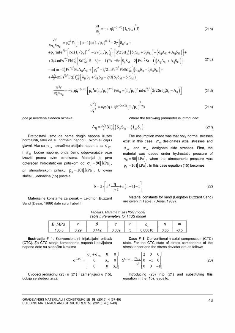
GRAĐEVINSKI MATERIJALI I KONSTRUKCIJE 58 (2015) 4 (37-49) BUILDING MATERIALS AND STRUCTURES 58 (2015) 4 (37-49)
43
( )n
( 1)1 1 a s
f a I p F− η+∂= − ηξ
∂ξ (21b)
( ) ( )
( ) ( ) ( ) ( )( ) ( )( )}{
( )
m 1m
m 1 1 1m m m
n 22a 1 a ij kl
ij kln 11 1
a 1 a 1 a 2d ij kl ij kl ij kl ij kl
1 12d 2d ij kl ij kl ij kl
f p Fs n n 1 I p 2
p mFs n I p 2 I p 3 2SrI S S A A
3 4 mFs FbI SrI 5 3 m 1 Fs Sr S S 2 Fs Sr 1 S A A S
m m 1
−
−
−−
−− −
− −− −
∂ ⎡ ⎤= − α − γ δ δ +⎢ ⎥⎣ ⎦∂σ ∂σ⎡ ⎤ ⎡ ⎤+ α − γ ⋅ δ + δ − δ + δ +⎢ ⎥ ⎣ ⎦⎣ ⎦
⎡ ⎤+ − − + − + −⎢ ⎥⎣ ⎦− − ( )( )
( )
m 2 m 1m m
3m 12m
2 1 1ij kl a 2d ik jl ij kl3
3 3ik jl ik jl ij kl ij kl2d2
Fs FbA A p 3 2 mFs FbSrI
mFs Fb I S S 2 3 S S
− −
−
− −
−
+ − δ δ − δ δ +
⎡ ⎤+ β δ + δ − δ + δ⎣ ⎦
(21c)
( ) ( ) ( )m 1m
2n 1 n( 1) 1 1
1 a 1 a ij 1 a 2d ij ijij
f a p n I p Fs I p mFs 3 2SrI S A−−− η+ − −∂ ⎡ ⎤= − ηξ δ + −⎢ ⎥⎣ ⎦∂ξ∂σ
(21d)
( )n2
( 2)1 1 a2
f Fsa ( 1) I p− η+∂= η η + ξ
∂ξ (21e)
gde je uvedena sledeća oznaka: Where the following parameter is introduced:
( )323 3 2
ij 2d ik kj 2d ij2 3A I S S I−= β − δ (21f)
Pretpostavili smo da nema drugih napona izuzevnormalnih, tako da su normalni naponi u ovom slučaju iglavni. Ako sa xxσ označimo aksijalni napon, a sa yyσ
i zzσ bočne napone, onda ćemo odgovarajuće vezeizraziti prema ovim oznakama. Materijal je prvoopterećen hidrostatičkim pritiskom od [ ]0 90 kPaσ = ,
pri atmosferskom pritisku [ ]ap 101 kPa= . U ovomslučaju, jednačina (15) postaje
The assumption made was that only normal stresses exist in this case. xxσ designates axial stresses and
yyσ and zzσ designate side stresses. First, the material was loaded under hydrostatic pressure of
[ ]0 90 kPaσ = , when the atmospheric pressure was
[ ]ap 101 kPa= . In this case equation (15) becomes
( )22 n n n 1 11
⎡ ⎤ηδ = γ + − −⎢ ⎥η +⎣ ⎦
(22)
Materijalne konstante za pesak ‒ Leighton BuzzardSand (Desai, 1989) date su u Tabeli I.
Material constants for sand (Leighton Buzzard Sand) are given in Table I (Desai, 1989).
Tabela I. Parametri za HISS model Table I. Parameters for HISS model
[ ]E MPa ν β γ n 1a η m
103.8 0.29 0.442 0.089 3 0.00018 0.85 -0.5
Ilustracija # 1: Konvencionalni trijaksijalni pritisak(CTC). Za CTC stanje komponente napona i devijatoranapona date su sledećim izrazima
Case # 1: Conventional triaxial compression (CTC) state. For the CTC state of stress components of the stress tensor and the stress deviator are as follows
0 xx
CTC0
0
0 00 00 0
σ + σ⎡ ⎤⎢ ⎥σ = σ⎢ ⎥⎢ ⎥σ⎣ ⎦
, CTC xx2 0 0
S 0 1 03
0 0 1
⎡ ⎤σ ⎢ ⎥= −⎢ ⎥
⎢ ⎥−⎣ ⎦
(23)
Uvodeći jednačinu (23) u (21) i zamenjujući u (15),dobija se sledeći izraz:
Introducing (23) into (21) and substituting this equation in the (15), leads to:

GRAĐEVINSKI MATERIJALI I KONSTRUKCIJE 58 (2015) 4 (37-49) BUILDING MATERIALS AND STRUCTURES 58 (2015) 4 (37-49)
44
( )( )
( ) ( ) ( ) ( ) ( )
( ) ( )( ) ( )
( ) ( )( ) ( )
222 12 2 2a 1a 1 0 xx 0 xx
a a
0 xx
a
0 xx
a
0 xx
a
2 n 1 np a 12 p a 3 32p p1 1
n 22 1 33 p
n 21 33 p
n 21 323 p
1 2k n
n n 1 2
4k n n 1 2
2k 2n n 1 4
− η+−− η+− − η η+ ξη ξ σ +σ σ +σ−β −β
−−β σ +σ
−−β σ +σ
−−β σ +σ
δ = − + ⋅
⎧⎡ ⎤+ − α − γ −⎨⎢ ⎥
⎣ ⎦⎩⎡ ⎤
− − + − α − γ +⎢ ⎥⎣ ⎦
⎫⎡ ⎤+ − α − γ ⎬⎢ ⎥
⎣ ⎦⎭
(24a)
gde je: where:
( )
( )
( ){ }( ) ( )
22 5 41 1 21 1 2 9(1 )
2 21 2 1 2
2c 2 3 c 1 cc 1 3c 2 9 ck
c 2 3 c 2 c 1 3 1 c
− ν+ν
⎡ ⎤ ⎡ ⎤+ ⋅ + + − ν+ − − ν ⎣ ⎦⎣ ⎦= ⋅⎡ ⎤ ⎡ ⎤+ + − + − ν⎢ ⎥ ⎢ ⎥⎣ ⎦ ⎣ ⎦
(24b)
( ) ( )0 0 xx
xx a
n 23 3 11 p 1
c 1 n 2−σ σ +σ
σ −β
⎡ ⎤= + α − γ⎢ ⎥⎣ ⎦ (24c)
( ) ( ) ( ) ( ) ( ) ( )2
1 a 0 xx 0 0 xx31 a xx axx
2n 2 n 2a p 3 3 3 3 22 p p 3 11E
c 1 n 2η+
−η σ +σ σ σ +σσ −β−βξ σ
⎡ ⎤= ⋅ + α − γ +⎢ ⎥
⎣ ⎦ (24d)
Nakon nekoliko transformacija, jednačina (24) se može prikazati u formi
After few simple transformations the equation (24) can be written in the form
( )n 2 2
2 0 xx
a
2 13 1 kn n n 1 2 01 p 1 2k 3
−⎛ ⎞ − β⎡ ⎤ σ + ση +⎛ ⎞δ = + − α − γ + =⎜ ⎟⎢ ⎥ ⎜ ⎟η + −⎝ ⎠⎣ ⎦ ⎝ ⎠
(25)
Rešenje karakteristične jednačine stabilnosti (25) prikazano je na slici 2. Najnepovoljnije ravni - u pogledukritičnog naponskog stanja - biće one kod kojih ugao između totalnog napona i normale na ravan ima najvećuvrednost.
Solution to the characteristic equation of stability of deformation (25) is shown in Fig. 2. The least favorable planes, from the critical stress point of view, are those at which the angle between the total stress and normal vector to the plane has the maximum value.
Slika 2. Konvencionalna trijaksijalna kompresija - rešenje jednačine stabilnosti
Figure 2. Case of conventional triaxial compression - solution for stability equation
Kao što se vidi s dijagrama, nagib krive je negativan,ali je vrednost δ pozitivna (uslov dat izrazom (16)) ipostoji ravnomernost u opadanju u tom pravcu kavrednosti gde je krivina jednaka nuli. U tački gde je
0δ = (15), ta tačka površine je nazvana parabolička.Na osnovu prikazanog dijagrama, jasno se vidi da jekritična vrednost sračunata numeričkim postupkom
[ ]CTCxx 336 kPaσ = . Eksperimentalni podaci prikazani su
na slici 3. (na osnovu podataka prikazanih u Referenci
As can be seen from the diagram, slope of the curve is negative but δ is positive (condition given by the equation =δ 2U T V 0− ⋅ ) with relative equality in stress increment towards the value where y-axis approaches zero. At the point where y-axis is zero, that point is called parabolic ( =δ 2U T V 0− ⋅ = ). As clearly stated on the diagram, critical stress value for the numerical model [ ]CTC
xx 336 kPaσ = .
Experimental data is shown in Figure 3. (based on
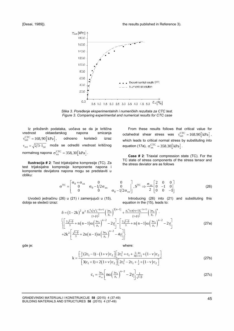
GRAĐEVINSKI MATERIJALI I KONSTRUKCIJE 58 (2015) 4 (37-49) BUILDING MATERIALS AND STRUCTURES 58 (2015) 4 (37-49)
45
[Desai, 1989]). the results published in Reference 3).
Slika 3. Poređenje eksperimentalnih i numeričkih rezultata za CTC test. Figure 3. Comparing experimental and numerical results for CTC case
Iz priloženih podataka, uočava se da je kritičnavrednost oktaedarskog napona smicanja
[ ]CTCoct 168,90 kPaτ = , odnosno koristeći izraz
oct 2d2 3 Iτ = ⋅ može se odrediti vrednost kritičnog
normalnog napona [ ]CTCxx 358,30 kPaσ = .
Ilustracija # 2: Test trijaksijalne kompresije (TC). Za
test trijaksijalne kompresije komponente napona ikomponente devijatora napona mogu se predstaviti uobliku:
From these results follows that critical value for octahedral shear stress was [ ]CTC
oct 168.90 kPaτ = ,
which leads to critical normal stress by substituting into equation (17a), [ ]CTC
xx 358.30 kPaσ = .
Case # 2: Triaxial compression state (TC). For the
TC state of stress components of the stress tensor and the stress deviator are as follows
0 xxTC
0 xx0 xx
0 00 1 2 00 0 1 2
σ + σ⎡ ⎤⎢ ⎥σ = σ − σ⎢ ⎥σ − σ⎣ ⎦
, TC xx2 0 0
S 0 1 02 0 0 1
⎡ ⎤σ⇒ −⎢ ⎥
⎢ ⎥−⎣ ⎦ (26)
Uvodeći jednačinu (26) u (21) i zamenjujući u (15),dobija se sledeći izraz:
Introducing (26) into (21) and substituting this equation in the (15), leads to:
( )( )
( )( ) ( ) ( ) ( )
( )( )
( ) ( ) ( ) ( )( ) ( )
242 14 2 2a 1a 1 0 0
3 3a a2 2
0 0
a a
0
a
2 n 1 np a 12 p a 3 32p p1 1
n 2 n 22 1 2 13 33 p 3 p
n 21 323 p
1 2k n
n n 1 2 n n 1 2
2k 2n n 1 4
− η+−− η+− − η η+ ξη ξ σ σ
−β −β− −−β −βσ σ
−−β σ
δ = − + ⋅
⎧⎡ ⎤ ⎡ ⎤+ − α − γ − + − α − γ⎨⎢ ⎥ ⎢ ⎥
⎣ ⎦ ⎣ ⎦⎩⎫⎡ ⎤
+ + − α − γ ⎬⎢ ⎥⎣ ⎦⎭
(27a)
gde je: where:
( ) ( )
( ) ( )
23 5 41 2 1 1 22 4(1 )
2 11 2 1 1 22
(2c 1) 1 c 2c c 1 ck
3(c 1) 2 1 c 2c 2c 1 c
− ν+ν
⎡ ⎤⎡ ⎤− − + ν + + + − ν⎣ ⎦ ⎣ ⎦=⎡ ⎤⎡ ⎤+ + + ν − + + − ν⎣ ⎦ ⎣ ⎦
(27b)
( )0 0
xx a
n 23 3 11 p 1
c n 2−σ σ
σ −β⎡ ⎤= α − γ⎢ ⎥⎣ ⎦
(27c)

GRAĐEVINSKI MATERIJALI I KONSTRUKCIJE 58 (2015) 4 (37-49) BUILDING MATERIALS AND STRUCTURES 58 (2015) 4 (37-49)
46
( ) ( ) ( ) ( ) ( ) ( )2
1 a 0 0 031 a xx axx
2n 2 n 2a p 3 3 3 3 32 p p 4 11E
c n 2η+
−η σ σ σσ −β−βξ σ
⎡ ⎤= α − γ +⎢ ⎥⎣ ⎦ (27d)
Nakon transformacija, jednačina (27) može seprikazati u formi
After few simple transformations the equation (27) can be written in the form
( )n 2 2
2 0
a
2 13 1 kn n n 1 2 01 p 1 2k 3
−⎛ ⎞ − β⎡ ⎤ ση +⎛ ⎞δ = + − α − γ + =⎜ ⎟⎢ ⎥ ⎜ ⎟η + −⎝ ⎠⎣ ⎦ ⎝ ⎠
(28)
Rešenje karakteristične jednačine stabilnosti (28) prikazano je na slici 4.
Solution to the characteristic equation of stability of deformation (28) is shown in Fig. 4.
Slika 4. Primer trijaksijale kompresije -Rešenje jednačine stabilnosti Figure 4. Case of triaxial compression - solution for stability equation
U tački gde je 0δ = (15), na osnovu prikazanog
dijagrama, kritična vrednost aksijalnog napona sraču-nata numeričkim postupkom jeste [ ]TC
xx 99,50 kPaσ = .
Eksperimentalni podaci prikazani su na slici 5. (na osnovu podataka prikazanih u ref. [Desai, 1989]). Iz priloženih podataka se vidi da je kritična vrednostoktaedarskog napona smicanja [ ]TC
oct 73,10 kPaτ = , odno-
sno, korišćenjem izraza oct 2d2 3 Iτ = ⋅ , može se
odrediti vrednost kritičnog normalnog napona
[ ]TCxx 103,36 kPaσ = .
At the point where 0δ = (15) (for zero y-axis) as clearly shown on the diagram, critical stress value calculated using the numerical model is
[ ]TCxx 99.50 kPaσ = . Experimental data is shown in
Figure 5 (based on published results from reference Desai 1989). From these results follows that critical value for the octahedral shear stress was
[ ]TCoct 73.10 kPaτ = , which leads to critical normal stress
of [ ]TCxx 103.36 kPaσ = .
Slika 5. Poređenje eksperimentalnih i numeričkih rezultata za TC test Figure 5. Comparing experimental and numerical results for TC case
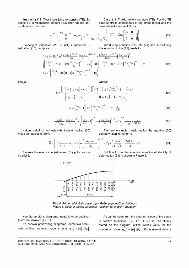
GRAĐEVINSKI MATERIJALI I KONSTRUKCIJE 58 (2015) 4 (37-49) BUILDING MATERIALS AND STRUCTURES 58 (2015) 4 (37-49)
47
Ilustracija # 3: Test trijaksijalne ekstenzije (TE). Zastanje TE komponentalni naponi i devijator napona datisu sledećim izrazima
Case # 3: Triaxial extension state (TE). For the TE state of stress components of the stress tensor and the stress deviator are as follows
0 xxTE
0 xx0 xx
0 00 2 00 0 2
σ − σ⎡ ⎤⎢ ⎥σ = σ + σ⎢ ⎥σ + σ⎣ ⎦
, TE xx2 0 0
S 0 1 02 0 0 1
−⎡ ⎤σ= ⎢ ⎥
⎢ ⎥⎣ ⎦ (29)
Uvođenjem jednačine (29) u (21) i zamenom u jednačinu (15), dobija se:
Introducing equation (29) into (21) and substituting this equation in the (15), leads to:
( )( )
( ) ( ) ( ) ( ) ( )
( ) ( )( ) ( ) ( ) ( )
( ) ( )
222 12 2 2a 1a 1 0 xx 0 xx
a a
0 xx 0 xx
a a
0 xx
a
2 n 1 np a 12 p a 3 32p p1 1
n 2 n 22 1 13 33 p 3 p
n 21 323 p
1 2k n
n n 1 2 4k n n 1 2
2k 2n n 1 4
− η+−− η+− − η η+ ξη ξ σ −σ σ −σ+β +β
− −+β +βσ −σ σ −σ
−+β σ −σ
δ = − + ⋅
⎧⎡ ⎤ ⎡ ⎤+ − α − γ − − + − α − γ⎨⎢ ⎥ ⎢ ⎥
⎣ ⎦ ⎣ ⎦⎩⎫⎡ ⎤
+ + − α − γ ⎬⎢ ⎥⎣ ⎦⎭
(30a)
gde je: where:
( )
( )( ){ }
( ) ( )
22 5 421 21 1 21 1 2 3 9(1 )3 9
2 22 11 2 1 23 3
2c c 1 cc c ck
c c 2 c 1 c
− ν+ν
⎡ ⎤ ⎡ ⎤− + + − ν− − − ν ⎣ ⎦⎣ ⎦= ⋅⎡ ⎤ ⎡ ⎤− + + + − ν⎢ ⎥ ⎢ ⎥⎣ ⎦ ⎣ ⎦
(30b)
( ) ( )0 0 xx
xx a
n 23 3 11 p 1
c 1 n 2−σ σ −σ
σ +β
⎡ ⎤= − α − γ⎢ ⎥
⎣ ⎦ (30c)
( ) ( ) ( ) ( ) ( ) ( )2
1 a 0 xx 0 0 xx31 a xx axx
2n 2 n 2a p 3 3 3 3 22 p p 3 11E
c 1 n 2η+
−η σ −σ σ σ −σσ +β+βξ σ
⎡ ⎤= ⋅ − α − γ +⎢ ⎥
⎣ ⎦ (30d)
Nakon nekoliko jednostavnih transformacija, (30) može se napisati u formi:
After some simple transformation the equation (30) can be written in the form:
( )n 2 2
2 0 xx
a
2 13 1 kn n n 1 2 01 p 1 2k 3
−⎛ ⎞ + β⎡ ⎤ σ − ση +⎛ ⎞δ = + − α − γ + =⎜ ⎟⎢ ⎥ ⎜ ⎟η + −⎝ ⎠⎣ ⎦ ⎝ ⎠
(31)
Rešenje karakteristične jednačine (31) prikazano jena slici 6.
Solution to the characteristic equation of stability of deformation (31) is shown in Figure 6.
Slika 6. Primer trijaksijale ekstenzije - Rešenje jednačine stabilnosti Figure 6. Case of triaxial extension - solution for stability equation.
Kao što se vidi s dijagrama, nagib krive je pozitivan(uslov dat izrazom 0δ ).
Na osnovu prikazanog dijagrama, numerički sraču-nata kritična vrednost napona jeste [ ]TE
xx 80 kPaσ = .
As can be seen from the diagram, slope of the curve is positive (condition =δ 2U T V 0− ⋅ ). As clearly stated on the diagram, critical stress value for the numerical model [ ]TE
xx 80 kPaσ = . Experimental data is

GRAĐEVINSKI MATERIJALI I KONSTRUKCIJE 58 (2015) 4 (37-49) BUILDING MATERIALS AND STRUCTURES 58 (2015) 4 (37-49)
48
Eksperimentalni podaci prikazani su na slici 7. (Desai, 1989). Kritična vrednost oktaedarskog napona smicanjajeste [ ]TE
oct 58,54 kPaτ = , odnosno može se odrediti
vrednost kritičnog normalnog napona
[ ]TExx 82,80 kPaσ = .
shown in Figure 7. (based on published results Desai, 1989). From these results follows that critical value for octahedral shear stress was [ ]TE
oct 58,54 kPaτ = , which
leads to critical normal stress by substituting into equation (17a) [ ]TE
xx 82,80 kPaσ = .
Slika 7. Poređenje eksperimentalnih i numeričkih rezultata za TE test Figure 7. Comparing experimental and numerical results for TE case.
ANALIZA REZULTATA Očigledno je da postoji dobro slaganje između
rezultata dobijenih numeričkim postupkom i eksperimen-talnih rezultata. Razlika između kritičnog naponaodređenih numeričkim postupkom i odgovarajućiheksperimentalnih vrednosti za TE test jeste 3.4%, za TCtest je 3.7%, dok je za CTC razlika 6.2%.
Prikazan numerički kriterijum za određivanje kritičnetačke pogodan je sa stanovišta praktične primene zaanalizu stabilnosti deformacije geomehaničkih materijalau zavisnosti od geometrije, graničnih uslova i karakteraopterećenja.
Klasični rezultati prikazani u radovima (Hill, 1950),(Rudnicki i sar., 1975) i (Rice, 1976) idu i korak dalje idefinišu ugao linije nestabilnosti tečenja. Ugao linijenestabilnosti tečenja možda se može i zamisliti kao ugaoanalogan lokalizovanju plastične deformacije i pojavivrata u testu zatezanja u metalnim uzorcima. Međutim,takva analogija primenjena na granularne materijale nemože se funkcionalno povezati sa uglom unutrašnjegtrenja u Mohr-Coulomb-ovom kriterijumu tečenja. U ovom radu ugao linije nestabilnosti tečenja, kaoparameter od interesa, nije definisan.
ANALYSIS OF RESULTS
Experimental and calculated numerical modulation values for critical stress are shown in Table II. It is obvious that there is good agreement between them. Percent difference between critical values predicted with numerical model and experimental results for TE test is only 3.4 %, for TC it is 3.7 % while for CTC it is 6.2 %.
Presented numerical criterion to determine critical loading point is useful from the practical point of view for the analysis of the deformation stability for geomechanical material for defined geometry, boundary conditions and loading path.
Classical results presented in work by Hill, Rudnicki and Rice, go a step further into defining the angle of instability for plastic flow. It is possible to think of this angle as analogous to the onset of localization of plastic deformation and beginning of necking in metallic samples. However, in that analogy for metal samples, angle at which macroscopic slip occurs and the begin-ning of plastic deformation and angle of necking and the beginning of local deformation are not functionally related. If analogy is applied to granular material, it means that angle of plastic instability is not be related to the angle of internal friction in a Mohr-Coulomb approach to plastic flow. In the presented paper, angle of plastic deformation instability for granular material was not considered to be the parameter of interest.

GRAĐEVINSKI MATERIJALI I KONSTRUKCIJE 58 (2015) 4 (37-49) BUILDING MATERIALS AND STRUCTURES 58 (2015) 4 (37-49)
49
ZAKLJUČAK
Prikazana je analiza uslova stabilnosti za granularnimaterijal. Rezultati dobijeni numeričkom analizom -korišćenjem HISS konstitutivnog modela - upoređeni sus publikovanim dijagramima za pesak (Leighton BuzzardSand) u eksperimentalnim uslovima trijaksijalnekompresije i zatezanja. Vrednosti za kritični napon unumeričkom testu niže su za 3-6 % od vrednosti uodgovarajućem eksperimentalnom testu. Nedovoljnoširoka primena HISS modela možda proističe iz potrebeza relativno velikim brojem materijalnih parametara (osam), kao i zbog njihove ograničene zastupljenosti u literaturi.
CONCLUSION
Criterion for stability of deformation in geomechanical materials is presented. Results obtained using HISS model for numerical analysis were compared with experimental results for particular sand material (Leighton Buzzard Sand) under triaxial compression and extension. Values for critical stress were 3-6 % lower in the numerical prediction compared with experimental data. That small difference in critical values may be considered as a good agreement. However, the main drawback of the HISS model may be its requirement for eight material parameters and limited availability of those parameters in the published literature.
LITERATURA REFERENCES
[1] Borst, de R., „Bifurcations in Finite ElementsModels with a Non-associated Flow Law”, Int. J. Numer. Anal. Meth.Geomech.,12(1), pp 99-117 (1988).
[2] Desai, C.S, Somasundaram, S. and G.Frantziskonis, G. „A HISS approach for constitutive modeling of geological materials”, Int. J. Num.Anal. Meth. Geom.,10(3), pp 225-257, (1987).
[3] Desai, C.S., „Notes for Advanced School-Numerical Methods in Geomechanics IncludingModelling”, Udine, Italy, July 10-14, (1989).
[4] Drucker, D.C., „Some Implications of WorkHardening and Ideal Plasticity”, Quarterly ofApplied Math., 7(4), pp 411-418 (1950).
[5] Drucker, D.C., „A Definition of Stable InelasticMaterial”, ASME Journal of Applied Mechanics, 26,pp 106-112 (1959).
[6] Hill, R., The mathematical theory of plasticity,Clarendon Press, Oxford, England (1950).
[7] Lelović, V.S., „Constitutive Equations for Sand andTheir Application in Numerical Analysis of StripFoundation Behavior”, PhD thesis, Civil Engin.Faculty, Universite Belgrade, (2012).
[8] Mandel, J., „Conditions de Stabilite et Postulat de Drucker”, Proc. IUTAM Symp. Rheology and Soil Mechanics, Grenoble (Ed. Kravtchenko, J. and Sirieys, P.M.), pp 57-58, (1964).
[9] Molenkamp, F., „Comparison of frictional material models with respect to shear band initiation", Geotechnique, 35, pp 127-143 (1985).
[10] Mroz, Z., „Nonassociated flow laws in plasticity”, J. de Mechanique, 2(1), pp 21-42 (1963)
[11] Rice, J.R., „The Localization of Plastic Deformation”, Proc. 14th Int. Cong. Theoretical and Appl. Mech., Delft (Ed. W.T. Koiter),1, pp 207-220, Delft, North-Holland, Amsterdam (1976).
[12] Rudnicki, J.W., and Rice, J.R., „Conditions for the Localization of Deformation in Pressure-Sensitive Dilatant Materials”, J.Mech.Phys.Solids, 23, pp 371-394 (1975).
[13] Vardoulakis, I., „Shear band Inclination and Shear Modulus of Sand in Biaxial Tests”, Int. J. Numer. Anal. Meth. Geomech.,4(2), pp 103-121 (1980).
REZIME
KRITERIJUM STABILNOSTI DEFORMACIJE ELASTOPLASTIČNIH MATERIJALA
Selimir V. LELOVIČ Određivanje kritične tačke moguće je svesti na
određivanje onog stanja pri kome dolazi do promeneznaka drugog izvoda funkcije tečenja. U ovom raduodređeno je kritično opterećenje geomehaničkogmaterijala numeričkim postupkom, korišćenjeminkrementalno iterativnog algoritma za različite putanjenapona. Konstitutivne jednačine za hijerarhijski model(hierarchical single surface model - HISS) primenjene suda bi se opisalo ponašanje granularnog materijala u tokudeformacije. Rezultati dobijeni numeričkom analizomupoređeni su sa eksperimentalnim rezultatima za pesak(Leighton Buzzard Sand).
Ključne reči: stabilnost, gubitak eliptičnosti, krivapovrši tečenja, kritično opterećenje, numerička metoda
SUMMARY
CONDITIONS FOR STABILITY OF DEFORMATION IN ELASTO-PLASTIC MATERIALS
Selimir V. LELOVIC It is possible to look at the critical point determination
as a sign change in the second derivative of the yield function. Numerical method in determining critical stress in geomechanical material using an iterative algorithm for different loading paths is presented. The constitutive relationships of the hierarchical single surface (HISS) model were used to describe the granular material during deformation. Critical stresses under applied triaxial compression and extension obtained numerically were compared with published experimental results for Leighton Buzzard Sand
Key words: stability, loss of ellipticity, curvature of yield surface, critical loading, numerical solution

GRAĐEVINSKI MATERIJALI I KONSTRUKCIJE 58 (2015) 4 (37-49) BUILDING MATERIALS AND STRUCTURES 58 (2015) 4 (37-49)
50

GRAĐEVINSKI MATERIJALI I KONSTRUKCIJE 58 (2015) 4 (51-69) BUILDING MATERIALS AND STRUCTURES 58 (2015) 4 (51-69)
51
UNAKRSNO LAMELIRANI DRVENI ELEMENTI U SAVREMENIM DRVENIM KONSTRUKCIJAMA ZGRADA – primena i proračun
CROSS LAMINATED TIMBER ELEMENTS IN CONTEMPORARY TIMBER
STRUCTURES OF BUILDINGS – application and design
Ljiljana KOZARIĆ Aleksandar PROKIĆ Miroslav BEŠEVIĆ
STRUĆNI RAD PROFESSIONAL PAPER
UDK: 624.011.1doi: 10.5937/grmk1504051K
1 UVOD
Drvo je jedan od najstarijih građevinskih materijala ipored kamena je dugi niz godina bio osnovni materijal zagrađenje. Njegove karakteristike omogućavaju visokstepen prefabrikacije, brzu montažu na terenu i trenutnuuseljivost. Zbog velike požarne otpornosti u požaru negubi nosiva svojstva, odnosno mehaničke karakteristikene menjaju se bitno prilikom visokih temperatura. Drvenekonstrukcije su pet puta lakše od armiranobetonskih, pamogu lakše preuzeti seizmičke sile i predstavljaju dobarizbor u trusnim područjima. Objekti izgrađeni od drvetaimaju visoku energetsku efikasnost.
Poslednjih decenija, drvo se sve više primenjuje uizgradnji modernih arhitektonskih građevina (npr. sportskih objekata, stambenih zgrada, mostova) zahvaljujući boljem poznavanju drveta kao materijala, primeni savremenih drvenih konstrukcija i upotrebikvalitetnih spojnih sredstava. Konstruktivni elementisavremenih drvenih konstrukcija bazirani su prvenstvenona savremenim proizvodima od drveta kao što sulepljeno lamelirano i unakrsno lamelirano drvo.
Ljiljana Kozarić, dipl. inž. građ., Univerzitet u Novom Sadu, Građevinski fakultet Subotica, Kozaračka 2a, Subotica, Srbija, tel.: 024 554 300, e-mail:[email protected] Prof.dr Aleksandar Prokić, dipl. inž. građ., Univerzitet u Novom Sadu, Građevinski fakultet Subotica, Kozaračka 2a, Subotica, Srbija, tel.: 024 554 300 e-mail: [email protected] Prof.dr Miroslav Bešević, dipl. inž. građ., Univerzitet u Novom Sadu, Građevinski fakultet Subotica, Kozaračka 2a, Subotica, Srbija, tel.: 024 554 300 e-mail [email protected]
1 INTRODUCTION
Wood is one of the oldest building materials and along with stone it is the basic building material. Its characteristics allow for a high degree of prefabrication, quick assembly, and immediate utilization. Wood has great fire resistance, and during the fire retains its characteristics, i.e. its mechanical properties do not change significantly due to high temperatures. Timber constructions are five times lighter than reinforced concrete, thus they are better capable of weathering seismic forces and stand out as material of choice for earthquake prone areas. Timber constructions have high energy efficiency.
Within last few decades, wood has been increasingly used in modern architectural buildings (sports’ arenas, residential buildings and bridges) thanks to better understanding of wood as a material, utilization of modern timber construction and high quality connections. Construction elements for contemporary timber constructions are primarily based upon contemporary products such as glued laminated timber and cross laminated timber.
Ljiljana Kozarić, dipl.inž. građ., University of Novi Sad, Faculty of Civil Engineering, Subotica, Kozaračka 2a, Serbia, tel: 024 554 300, e-mail: [email protected] Prof.dr Aleksandar Prokić, dipl.inž. građ., University of Novi Sad, Faculty of Civil Engineering, Subotica, Kozaračka 2a, Serbia, tel: 024 554 300, e-mail: [email protected] Prof.dr Miroslav Bešević, dipl.inž. građ., University of Novi Sad, Faculty of Civil Engineering, Subotica, Kozaračka 2a, Serbia, tel: 024 554 300 e-mail: [email protected]
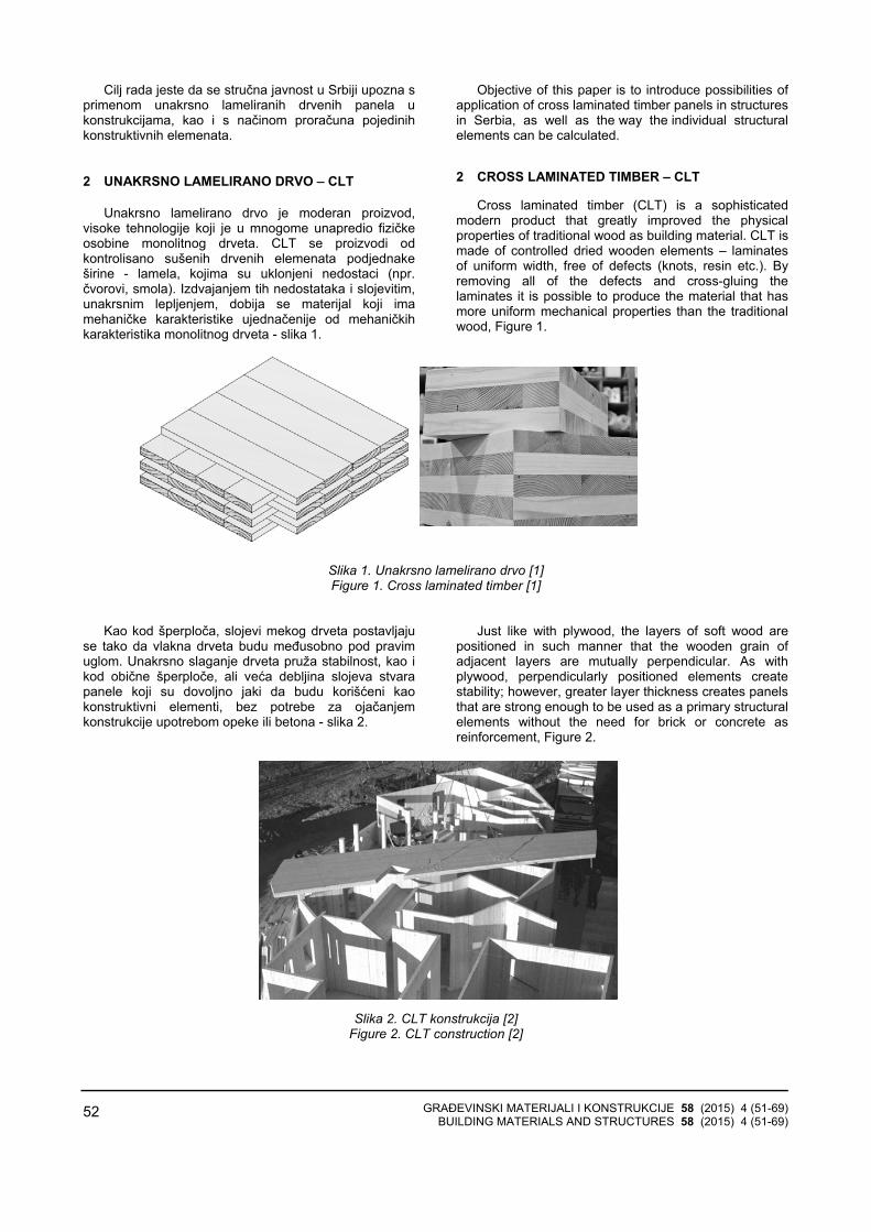
GRAĐEVINSKI MATERIJALI I KONSTRUKCIJE 58 (2015) 4 (51-69) BUILDING MATERIALS AND STRUCTURES 58 (2015) 4 (51-69)
52
Cilj rada jeste da se stručna javnost u Srbiji upozna sprimenom unakrsno lameliranih drvenih panela ukonstrukcijama, kao i s načinom proračuna pojedinihkonstruktivnih elemenata.
2 UNAKRSNO LAMELIRANO DRVO ‒ CLT
Unakrsno lamelirano drvo je moderan proizvod, visoke tehnologije koji je u mnogome unapredio fizičkeosobine monolitnog drveta. CLT se proizvodi odkontrolisano sušenih drvenih elemenata podjednakeširine - lamela, kojima su uklonjeni nedostaci (npr. čvorovi, smola). Izdvajanjem tih nedostataka i slojevitim,unakrsnim lepljenjem, dobija se materijal koji imamehaničke karakteristike ujednačenije od mehaničkihkarakteristika monolitnog drveta - slika 1.
Objective of this paper is to introduce possibilities of application of cross laminated timber panels in structures in Serbia, as well as the way the individual structural elements can be calculated.
2 CROSS LAMINATED TIMBER – CLT
Cross laminated timber (CLT) is a sophisticated modern product that greatly improved the physical properties of traditional wood as building material. CLT is made of controlled dried wooden elements – laminates of uniform width, free of defects (knots, resin etc.). By removing all of the defects and cross-gluing the laminates it is possible to produce the material that has more uniform mechanical properties than the traditional wood, Figure 1.
Slika 1. Unakrsno lamelirano drvo [1] Figure 1. Cross laminated timber [1]
Kao kod šperploča, slojevi mekog drveta postavljajuse tako da vlakna drveta budu međusobno pod pravimuglom. Unakrsno slaganje drveta pruža stabilnost, kao ikod obične šperploče, ali veća debljina slojeva stvarapanele koji su dovoljno jaki da budu korišćeni kaokonstruktivni elementi, bez potrebe za ojačanjemkonstrukcije upotrebom opeke ili betona - slika 2.
Just like with plywood, the layers of soft wood are positioned in such manner that the wooden grain of adjacent layers are mutually perpendicular. As with plywood, perpendicularly positioned elements create stability; however, greater layer thickness creates panels that are strong enough to be used as a primary structural elements without the need for brick or concrete as reinforcement, Figure 2.
Slika 2. CLT konstrukcija [2] Figure 2. CLT construction [2]

GRAĐEVINSKI MATERIJALI I KONSTRUKCIJE 58 (2015) 4 (51-69) BUILDING MATERIALS AND STRUCTURES 58 (2015) 4 (51-69)
53
Poprečni preseci CLT panela sadrže najmanje triunakrsno zalepljene lamele, a najčešće pet ili sedam. Slojevi s lamelama postavljeni su naizmenično podpravim uglom, ali se pojedini slojevi mogu i duplirati,stvarajući tako panele s većom nosivošću u potrebnompravcu - slika 3. Visina lamela u CLT panelima varira od16 mm do 51 mm, a širina od 60 mm do 240 mm.
Spoljne lamele u zidnim CLT panelima postavljaju seuspravno, paralelno sa silom gravitacije, radimaksimalnog iskorišćenja vertikalne nosivosti panela. Kod podnih i krovnih CLT panela, spoljne lamelepostavljaju se paralelno s pravcem dominantnogopterećenja. Spoljašnje površine panela - zbog estetskihzahteva, te zbog zahteva vatrootpornosti i zvučneizolacije - mogu se obložiti gips-kartonskim pločama ilinekom drugom pogodnom oblogom.
A CLT cross section contains a minimum of three cross-glued laminates, but most often five or seven. Alternate layers are mutually perpendicular; however, it is possible to double certain layers so that greater strength can be achieved in a desired direction, Figure 3. Laminate height within a CLT varies from 16 to 51 mm while width varies between 60mm and 240mm.
Outside laminates within a CLT wall are positioned vertically, parallel with the gravitational forces so that vertical potential of the panel can be maximized, while in CLT panels for floor and roof applications are placed parallel with the direction of dominant forces. To meet aesthetic, fireproof, and insulation requirements, the exposed surfaces of the panels can be covered with gypsum or similar appropriate finish.
Slika 3. Poprečni preseci CLT panela [3] Figure 3. CLT Panel cross sections [3]
U Evropi, CLT paneli najčešće se proizvode odčetinara klase čvrstoće C24, vlažnosti 12±2% - [4].Dimenzije panela zavise od raspoložive tehnologijeproizvođača, ali i od načina transporta.
Zidni CLT paneli isporučuju se na gradilište s većformiranim otvorima po projektu. Tipičan zidni CLT panelprikazan je na slici 4.
In Europe, CLT is most often manufactured from conifers grade C24, and moisture content 12±2%, [4]. Panel dimensions are dictated by manufacturer technology and mode of transportation.
Wall CLT panels are delivered to a construction site where the wall openings have already been formed according to design. A typical CLT wall panel is shown in Figure 4.
Slika 4. Zidni CLT paneli [3] Figure 4. Typical Wall CLT panel [3]
4,8∼15 cm
do 3 m to 3 m
do 18 m to 18 m

GRAĐEVINSKI MATERIJALI I KONSTRUKCIJE 58 (2015) 4 (51-69) BUILDING MATERIALS AND STRUCTURES 58 (2015) 4 (51-69)
54
Podne i krovne konstrukcije dobijaju se horizontalnimili kosim slaganjem osnovnih panela. Tipične dimenzijeosnovnog podnog i krovnog panela prikazane su na slici5.
Među najveće evropske proizvođače CLT panela svrstavaju se: KLH (Austrija, UK, Švedska), Binderholz(Austrija), Martinsons (Švedska), Moelven (Norveška), Stora Enso (Austrija), Thoma Holz GmbH (Austrija), FinnForest Merk (Nemačka, UK), HMS (Nemačka).
Svi navedeni proizvođači koriste isti procesproizvodnje, glavna razlika je u dimenzijama CLT panelai u izboru lepka.
Osnovne fizičko-mehaničke karakteristike CLT panela s daskama od četinara klase čvrstoće C24 (minimalno 90%) i C16 (maksimalno 10%) date su uTabeli 1.
Floor and roof construction are manufactured by arranging the basic panels in horizontal or angular pattern. Typical dimensions of basic floor or roof panel are depicted in Figure 5. Some of the biggest European CLT panels manufacturers are: KLH (Austria, UK, Sweden), Binderholz (Austria), Martinsons (Sweden), Moelven (Norway), Stora Enso (Austria), Thoma Holz GmbH (Austria), FinnForest Merk (Germany, UK) and HMS (Germany).
All of the above listed manufacturers use the same manufacturing process, while the main differences are panels’ dimensions, and the choice of glue.
Basic physical and mechanical properties of CLT panels with planks made out of conifers grade C24 (minimum 90%) and C16 (maximum 10%) are listed in Table 1.
Slika 5. Podni i krovni CLT paneli [3] Figure 5. Floor and Roof CLT panel [3]
Tabela 1. Osnovne fizičko-mehaničke karakteristike CLT panela [5] Table 1. Basic physical and mechanical properties of CLT panels [5]
Karakteristične čvrstoće [N/mm²] / Characteristic strength [N/mm²]
Savijanje / Bending fm,k 24
Zatezanje paralelno s vlaknima / Tension along the grain ft,0,k 16,5
Zatezanje upravno na vlakna / Tension across the grain ft,90,k 0,12
Pritisak paralelno s vlaknima / Compression along the grain fc,0,k 24‒30
Pritisak upravno na vlakna / Compression across the grain fc,90,k 2,7
Karakteristične krutosti [N/mm²] / Characteristic stiffness [N/mm²]
Srednja vrednost modula E paralelno s vlaknima Median value of modulus of elasticity E along the grain E0,mean 12000
Srednja vrednost modula E upravno s vlaknima Median value of modulus of elasticity E across the grain E90,mean 370
Zapreminska masa [kg/m³] / Specific weight [kg/m³] ρ 480‒500 Koeficijent toplotne provodljivosti [W/(mK)] Thermal conductivity coefficient [W/(mK)] λ 0,13
Dopušteni ugib / Allowable deflection umax l/250
do 3 m to 3 m
do 18 m to 18 m
4,8∼50 cm

GRAĐEVINSKI MATERIJALI I KONSTRUKCIJE 58 (2015) 4 (51-69) BUILDING MATERIALS AND STRUCTURES 58 (2015) 4 (51-69)
55
U svetu, CLT konstrukcije doživele su veliki uspon izsledećih razloga: neuporedivo su čvršće i imaju boljestatičke osobine od monolitnog drveta, nemaju sklonostka uvijanju, pojava napuklina svedena je na minimum, velika požarna otpornost, visoka otpornost na potres.
Upotrebom CLT panela smanjuje se vremeizgradnje, jer se drveni elementi isporučuju kaoprefabrikovani zidovi ili moduli, koji se zatim brzouklapaju na gradilištu. Izgradnja CLT konstrukcije je oko30% brža u poređenju sa odgovarajućom betonskomkonstrukcijom. Takođe, drvo je „suv” građevinskimaterijal, njemu ne treba vreme da se osuši ili očvrsne, kao što je to slučaj s betonom ili opekom. Za CLT panelekoristi se mekano drvo koje raste brzo i kog ima uizobilju, pa je i cena CLT konstrukcija niža od 5 do 10% od odgovarajućih betonskih ili čeličnih [6].
Drvo je obnovljiv izvor, što je velika prednost, kao i tošto u toku rasta vezuje velike količine ugljen-dioksida. Zaproizvodnju tone betona potrebno je pet puta, za čelik 24 puta, dok je za tonu aluminijuma potrebno 126 puta višeenergije nego za proizvodnju materijala od drveta. Drvoje i mnogo bolji izolator i to pet puta bolji od betona i čak350 puta bolji nego što je to čelik [7].
3 PRIMERI IZVEDENIH CLT KONSTRUKCIJA
3.1 Stambena zgrada Forte u Melburnu
Zgrada Forte trenutno je najviša stambena zgradaizgrađena od drveta na svetu. Projektovala ju je iizgradila kompanija Lend Lease 2013. godine. Visoka je32,17 metara. U prizemlju su poslovni prostori, a naspratovima ima 23 stana - slika 6.
Worldwide, CLT became greatly popular for the following reasons: CLT is much stronger with far more superior mechanical properties than traditional wood, no bending tendency, minimal fractures appearance, high resistance to fire, and resilience to earthquakes.
Since CLT is delivered to construction site in prefabricated or modular form it takes on average 30% less time to complete CLT than a comparable concrete or brick and mortar project. Contributing to the speed of completion is also the fact that unlike concrete, timber is “dry” building material that does not require either the time to dry, or the time to cure and achieve its final strength. Fast growing easily accessible softwood keeps the price of CLT 5 to 10% lower than the competing concrete or steel construction [6].
Timber’s great advantage is that it is a renewable resource, and in the process of growth trees absorb great amount of carbon dioxide. To produce one ton of concrete, steel or aluminium it takes 5, 24 and 126 times more energy respectively than for the production of timber. Timber is 5 times better insulator than concrete and up to 350 times better than steel [7].
3 EXAMPLES OF CLT APPLICATIONS
3.1 Apartment building Forte in Melbourne, Australia
Forte is currently the tallest residential timber building in the world. The design and construction has been done in 2013 by Lend Lease. The apartment building is 32,17m tall. At the ground floor there are commercial spaces, and 23 apartments in the above floors, Figure 6.
Slika 6. Zgrada Forte u Melburnu
Figure 6. Forte Residential Building in Melbourne, Australia Osnovni konstruktivni elementi su drveni zidni paneli
i podne ploče. Za izgradnju je bilo potrebno 759 CLT panela, odnosno 485 tona drvene građe. Zgrada Forte jeprva stambena zgrada sertifikovana s pet zvezdaprograma Green Star As Built u Australiji.
Drvena građa u ovom objektu skladišti 761 tonuugljenika, a odabirom CLT konstrukcije količina ugljen-dioksida u atmosferi se smanjila ukupno za oko 1 451 tonu, jer bi se pri izgradnji sličnog objekta od betona iličelika, u atmosferu ispustio dodatan ugljen-dioksid. Ta
Basic design elements are wooden wall and floor panels. It took 759 CLT panels, or 485 tons of wooden material for construction. Forte residential building is the first Five Star Green Star as built rating in Australia. The wooden material in this building stores 761 ton of carbon, and by choosing CLT over concrete or steel the total amount of carbon dioxide released in the atmosphere has been reduced by 1,451 tons. This amount represents the equivalent of the carbon dioxide released by 345 cars during one year [8].

GRAĐEVINSKI MATERIJALI I KONSTRUKCIJE 58 (2015) 4 (51-69) BUILDING MATERIALS AND STRUCTURES 58 (2015) 4 (51-69)
56
količina ugljen-dioksida predstavlja 345 automobilamanje na ulici u toku jedne godine [8].
3.2 Stambena zgrada Stadthaus u Londonu
Zgrada Stadthaus sagrađena je 2008. godine uLondonu i pune dve godine bila je najviša drvenastambena zgrada na svetu. Ovu devetospratnicuprojektovala je kompanija Waugh Thistleton Architects.Podovi, plafoni, kućište lifta i stepeništa izrađeni su upotpunosti od drveta - slika 7.
3.2 Stadthaus Residential Building in London, UK
Stadthaus Residential building was built in 2008 and
for full two year was the world’s tallest timber residential building. This nine story building has been designed by Waugh Thistlton Architects. Floors, ceilings, elevator shaft and stair flights were built completely out of timber, Figure 7.
Slika 7. Zgrada Stadthaus u Londonu Figure 7. Stadthaus Residential Building in London, UK
Korisna površina stambene zgrade jeste 2.352 m2 i
za izgradnju bilo je potrebno 950 m3 CLT panela. Zidnipaneli bili su debljine 128 mm, a podni - 146 mm. Zaizgradnju jednog sprata bilo je potrebno tri dana. Upoređenju s betonskom konstrukcijom, projektanti suizborom CLT konstrukcije uštedeli dvadeset dve nedeljegradnje, što predstavlja uštedu u vremenu od oko 30%.
Drvo ugrađeno u Stadthaus čuva oko 186 tonaugljenika, dok bi se za čelik i beton koji se koriste ukonvencionalnom građevinarstvu, za sličnu građevinu, uatmosferu ispustilo oko 137 tona ugljen-dioksida uprocesu proizvodnje. Dakle, ovakav način gradnjesmanjio bi količinu ugljen-dioksida u atmosferi za oko323 tone [9].
3.3 Srednja škola u Noriču UK
Objekat se nalazi u Noriču i trenutno je najveća CLT konstrukcija u Ujedinjenom kraljevstvu. Sagrađena jekrajem 2009. godine. Glavni arhitekta bio je SheppardRobson. Korisna površina objekta iznosi 9.500 m2,a zaizgradnju bilo je potrebno 3.065 m3 CLT panela. Kompletna konstrukcija ovog trospratnog objektaizgrađena je za šesnaest nedelja. Fiskulturnu salu usklopu škole od 600 m2 (slika 8) montirala su četiriradnika za četiri dana. Za montažu jednog zidnog CLT panela dimenzije 3 m x 6 m debljine 15 cm, bilo je potrebno samo tri sata.
Buildings used area is 2,352 m2 and it took 950 m3 of CLT panels for construction. Wall panels’ thickness varies from 128 mm to 146 mm. It took three days for completion of one story. Compared to a concrete building construction, the CLT method is 22 weeks faster, which amounts to total time reduction of about 30%.
The amount of wood in Stadthaus stores 186 tons of carbon, while for construction of conventional steel or concrete building of this size 137 tons of carbon dioxide would have been released in the atmosphere. As a result, CLT method reduces the total carbon dioxide foot print for 323 tons [9].
3.3 High School in Norwich, UK
The School is located in Norwich and currently is the largest CLT construction in the United Kingdom. It was built in 2009. The lead architect was Sheppard Robson. Building’s used area is 9,500 m2, and it took 3,065 m3 of CLT panels for its completion. The construction of this three story building was completed in 16 weeks. The 600 m2 gymnasium within the school building was assembled by 4 workers in 4 days, Figure 8. It takes only 3 hours for the installation of one 3 m by 6 m wall CLT panel.
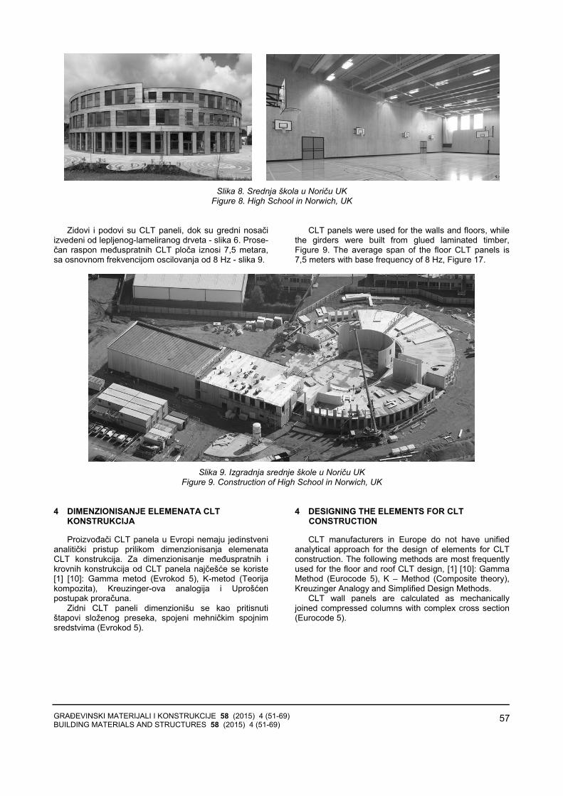
GRAĐEVINSKI MATERIJALI I KONSTRUKCIJE 58 (2015) 4 (51-69) BUILDING MATERIALS AND STRUCTURES 58 (2015) 4 (51-69)
57
Slika 8. Srednja škola u Noriču UK
Figure 8. High School in Norwich, UK Zidovi i podovi su CLT paneli, dok su gredni nosači
izvedeni od lepljenog-lameliranog drveta - slika 6. Prose-čan raspon međuspratnih CLT ploča iznosi 7,5 metara,sa osnovnom frekvencijom oscilovanja od 8 Hz - slika 9.
CLT panels were used for the walls and floors, while the girders were built from glued laminated timber, Figure 9. The average span of the floor CLT panels is 7,5 meters with base frequency of 8 Hz, Figure 17.
Slika 9. Izgradnja srednje škole u Noriču UK
Figure 9. Construction of High School in Norwich, UK 4 DIMENZIONISANJE ELEMENATA CLT
KONSTRUKCIJA
Proizvođači CLT panela u Evropi nemaju jedinstvenianalitički pristup prilikom dimenzionisanja elemenataCLT konstrukcija. Za dimenzionisanje međuspratnih ikrovnih konstrukcija od CLT panela najčešće se koriste[1] [10]: Gamma metod (Evrokod 5), K-metod (Teorijakompozita), Kreuzinger-ova analogija i Uprošćenpostupak proračuna.
Zidni CLT paneli dimenzionišu se kao pritisnutištapovi složenog preseka, spojeni mehničkim spojnimsredstvima (Evrokod 5).
4 DESIGNING THE ELEMENTS FOR CLT CONSTRUCTION
CLT manufacturers in Europe do not have unified analytical approach for the design of elements for CLT construction. The following methods are most frequently used for the floor and roof CLT design, [1] [10]: Gamma Method (Eurocode 5), K – Method (Composite theory), Kreuzinger Analogy and Simplified Design Methods.
CLT wall panels are calculated as mechanically joined compressed columns with complex cross section (Eurocode 5).

GRAĐEVINSKI MATERIJALI I KONSTRUKCIJE 58 (2015) 4 (51-69) BUILDING MATERIALS AND STRUCTURES 58 (2015) 4 (51-69)
58
4.1 Gamma metod
Gamma metod zasnovan je na Aneksu B Evrokoda 5 (EN 1995-1-1:2004) [11] koji je razvijen za grednenosače složenog poprečnog preseka, spojene mehani-čkim spojnim sredstvima krutosti k postavljenim najednakim rastojanjima s . Prilikom proračuna CLT pane-la, uzimaju se u obzir samo podužne lamele to jestlamele u pravcu delovanja opterećenja. One se modeli-raju kao gredni nosači koji su povezani „imaginarnim”mehaničkim spojnim sredstvima čija je krutost jednakamodulu smicanja upravno na vlakna poprečnih lamela. Smicanje podužnih lamela zanemaruje se ako je odnosraspona i visine lamele 30≥ .
Ovaj metod proračuna prikladan je za slobodno oslo-njene međuspratne i krovne CLT panele sa 3 ili 5 lamela.
4.1 Gamma method
Gamma method is based upon annex B of Eurocode 5(EN 1995-1-1:2004) [11] which has been developed for a girders with composite cross section joined with mechanical connectors with stiffness k distributed evenly over distance s. During the CLT design process only the longitudinal laminates are taken into consideration i.e. the laminates parallel with the loading direction. The laminates are modelled like beams whose stiffness is equal to the shear modulus along the grain of lateral laminates. Shearing of longitudinal laminates can be neglected of the ration of span to height of the laminate is 30≥ .
This design method is adequate for freely spanned floor and roof CLT panel with 3 or 5 laminates.
Legenda / Legend:
(1) razmak / span 1s modul pomerljivosti / displacement modulus 1K opterećenje / load 1F
(2) razmak / span 2s modul pomerljivosti / displacement modulus 2K opterećenje / load 2F
Slika 10. Model CLT panela sa 5 lamela [11] Figure 10. CLT Panel with 5 laminates [11]
Efektivna krutost na savijanje računa se premaizrazu
Effective stiffness can be calculated based on the following expression:
( ) ( )3
2
1
i i i i i iefi
EI E I E A aγ=
= +∑ (1)
gde su simboli definisani na slici 10, a γ predstavljameru efikasnosti veze i ima vrednost od 0 do 1. Kadnema spojnog sredstva u vezi 0 γ = a kod potpunokrute veze (potpunog sprezanja) 1.γ = Kod CLTpanela 0,85 0,99γ = ÷ .
U Evrokodu 5 γ definisana je kao
where the symbols have been defined in Figure 10, and γ represent the effectives of the connection with its value ranging from 0 to 1. For the connection with no connectors, 0 γ = , while for fully fixed connection (coupling) 1.γ = . For CLT panels 0,85 0,99γ = ÷
Eurocode 5 defines as:
2 1γ =
12
21 i i ii
i
E A sK l
πγ−
⎡ ⎤= +⎢ ⎥
⎣ ⎦
(2)
za 1i = i 3i = for 1i = and 3i =
spojno sredstvo connector
spojno sredstvo connector

GRAĐEVINSKI MATERIJALI I KONSTRUKCIJE 58 (2015) 4 (51-69) BUILDING MATERIALS AND STRUCTURES 58 (2015) 4 (51-69)
59
Uzimajući u obzir da je krutost „imaginarnih”mehaničkih spojnih sredstava jednaka modulu smicanjaupravno na vlakna poprečnih lamela
If taken into consideration that the stiffness of “imaginary” mechanical connectors is equal to the shear modulus along the grain of lateral laminates then:
i
i R
isG
hK b⋅
= (3)
gde je b širina panela (obično 1 m) ih visina poprečne lamele
RG modul smicanja upravno na vlakna poprečnihlamela
za CLT panele dobija se da je
where b is width of a panel (usually 1 m) ih is height of the lateral laminate
RG is shear modulus along the grain of lateral laminates
Expression for CLT panels is given as:
2 1γ =
12
21 i ii
i
R
hE Al G b
πγ−
⎡ ⎤= + ⋅⎢ ⎥
⎣ ⎦⋅
(4)
za 1i = i 3i = for 1i = and 3i =
Normalni napon računa se kao Normal stress can be calculated as
i max i global i localσ σ σ= + (5)
gde je where
( ) i i i
i globalef
E a MEI
γσ =
( )
0,5 i ii local
ef
E h MEI
σ =
(6)
4.2 K - metod (Blass&Fellmoser)
Prilikom proračuna ovom metodom, u obzir se uzima krutost svih lamela. Modul elastičnosti poprečnih lamelaračuna se kao
4.3 K - method (Blass&Fellmoser)
This design method includes the stiffness of all laminates. Modulus of elasticity of lateral laminates can be calculated as:
90 0 / 30 E E= (7)
Princip proračuna sličan je proračunu šperploča. Efektivne vrednosti napona i krutosti dobijaju se pomoćukoeficijenata ik - Tabela 2.
The method is similar to the design method for plywood. The values for stress and stiffness can be calculated by using the coefficient ik , Table 2.
Tabela 2. Efektivne vrednosti napona i krutosti CLT panela [12] Table 2. Normal Stress and Effective Stiffness Values [12]
Opterećenje Load
Pravac vlakana Grain direction
Efektivni napon Normal Stress
Efektivna krutost Effective Stiffness
Opterećenje normalno na ravan panela Load perpendicular to a panel
Paralelno s vlaknima Along the grain
fm,0,ef = fm,0 ⋅ k1 Em,0,ef = E0 ⋅ k1 Savijanje Bending Upravno na vlakna
Across the grain fm,90,ef = fm,0 ⋅ k2 ⋅ am / am-2 Em,90,ef = E0 ⋅ k2

GRAĐEVINSKI MATERIJALI I KONSTRUKCIJE 58 (2015) 4 (51-69) BUILDING MATERIALS AND STRUCTURES 58 (2015) 4 (51-69)
60
Opterećenje u ravni panela Load in the plane of a panel
Paralelno s vlaknima Along the grain
fm,0,ef = fm,0 ⋅ k3 Em,0,ef = E0 ⋅ k3 Savijanje Bending
Upravno na vlakna Across the grain fm,90,ef = fm,0 ⋅ k4 Em,90,ef = E0 ⋅ k4
Paralelno s vlaknima Along the grain
ft,0,ef = ft,0 ⋅ k3 Et,0,ef = E0 ⋅ k3 Zatezanje Tension Upravno na vlakna
Across the grain ft,90,ef = ft,0 ⋅ k4 Et,90,ef = E0 ⋅ k4
Paralelno s vlaknima Along the grain
fc,0,ef = fc,0 ⋅ k3 Ec,0,ef = E0 ⋅ k3 Pritisak Compression Upravno na vlakna
Across the grain fc,90,ef = fc,0 ⋅ k4 Ec,90,ef = E0 ⋅ k4
Koeficijenti ik definisani su u zavisnosti odopterećenja - Tabela 3.
Depending on the load coefficients ik are defined in Table 3.
Tabela 3. Vrednosti koeficijenata ik [12][3]
Table 3. Coefficients ik Values [12][3]
Opterećenje / Load ik
3 3 390 2 4 1
1 30
1 1 m m
m
E a a akE a
− −⎛ ⎞ − +…±= − − ⋅⎜ ⎟
⎝ ⎠
3 3 390 90 2 4 1
2 30 0
1 m m
m
E E a a akE E a
− −⎛ ⎞ − +…±= + − ⋅⎜ ⎟
⎝ ⎠
90 2 4 13
0
1 1 m m
m
E a a akE a
− −⎛ ⎞ − +…±= − − ⋅⎜ ⎟
⎝ ⎠

GRAĐEVINSKI MATERIJALI I KONSTRUKCIJE 58 (2015) 4 (51-69) BUILDING MATERIALS AND STRUCTURES 58 (2015) 4 (51-69)
61
90 90 2 4 14
0 0
1 m m
m
E E a a akE E a
− −⎛ ⎞ − +…±= + − ⋅⎜ ⎟
⎝ ⎠
Način određivanja rastojanja a CLT panela s petlamela ( 5m = ) prikazan je na slici 11.
Figure 11. Depicts the method to determine spans aCLT panels with 5 laminates ( 5m = ).
Slika 11. CLT panel sa 5 lamela [3]
Figure 11. CLT Panel with 5 laminates [3]
Efektivna krutost na savijanje od opterećenjaupravno na ravan panela jeste:
− paralelno s vlaknima
Effective bending stiffness perpendicular to the panel can be calculated as:
− along the grain
( )3
0 1 12
mef
b aEI E k⋅⋅⋅= (8)
− upravno na vlakna − across the grain
( )3
0 2 12
mef
b aEI E k⋅⋅⋅= (9)
gde b predstavlja širinu panela opterećenog upravno nasvoju ravan.
Normalni napon savijanja od opterećenja upravno naravan panela jeste:
− paralelno s vlaknima
where b represents the width of the panel perpendicular to its own plane.
Normal bending stress from the load perpendicular to the plane of the panel can be calculated as:
− along the grain
( ) 0
2m
mef
aM EEI
σ = ⋅ ⋅ (10)
− upravno na vlakna − across the grain
( )
20
2m
mef
aM EEI
σ −⋅ ⋅= (11)

GRAĐEVINSKI MATERIJALI I KONSTRUKCIJE 58 (2015) 4 (51-69) BUILDING MATERIALS AND STRUCTURES 58 (2015) 4 (51-69)
62
4.3 Kreuzinger-ova analogija
Kreuzinger pri proračunu uzima različite moduleelastičnosti i module smicanja podužnih i poprečnihlamela. Smicanje podužnih lamela se ne zanemaruje. Modul elastičnosti poprečnih lamela računa se po izrazu(7). Kreuzinger-ova analogija nije ograničena brojemlamela u panelu.
Ovom analogijom, CLT panel deli se u dve virtuelnegrede A i B - slika 12.
4.3 Kreuzinger Analogy
Design according to Kreuzinger considers different modules of elasticity and shear for longitudinal and lateral laminates. Longitudinal shear of laminates is also considered. Modulus of elasticity of lateral laminates can be calculated by using expression (7). Number of laminates is not a limiting factor in Kreuzinger Analogy.
This method divides the CLT panel into two virtual beams A and B as in Figure 12.
Slika 12. Kreuzinger-ova analogija [1]
Figure 12. Kreuznger Analogy [1]
Efektivna krutost Effective stiffness
( ) ( ) ( )3
2
1 112
n ni
i i i i ief A Bi i
hEI EI EI E b E A Z= =
= + ⋅ ⋅ ⋅= +∑ ∑ (12)
gde je ib širina panela (obično 1 m)
ih visina lamele
iZ rastojanje od težišta lamele do neutralne ose - slika 13.
where ib is width of a panel (usually 1 m)
ih is height of the laminate
iZ is the distance from the centroid of the laminate to the neutral axis, Figure 13.
Slika 13. Rastojanja iz kod CLT panela sa 5 lamela [10]
Figure 13. Distance iz with CLT panels with 5 laminates [10] 4.4 Proračun zidnih CLT panela
Zidni CLT paneli dimenzionišu se kao pritisnuti štapovi složenog preseka, spojeni mehničkim spojnimsredstvima. Postupak proračuna izložen je u Aneksu CEvrokoda 5 (EN 1995-1-1:2004) [11].
Metod proračuna zasnovan je na sledećimpretpostavkama:
− elementi su sistema proste grede, dužine l − elementi složenog preseka idu kontinualno duž
štapa. Efektivnu vitkost treba uzeti prema izrazu
4.4 Design Method for CLT Wall Panels
CLT wall panels are calculated as mechanically joined compressed columns with complex cross section.Design method is presented in annex C of Eurocode 5 (EN 1995-1-1:2004) [11].
The method is based upon following assumptions: − The elements are simple beams with length l , − The elements with the complex cross section run
longitudinally with the member. Effective slenderness shall be calculated using the
following expression:
totef
ef
AlI
λ = (13)
Greda A Beam A
Greda B Beam B

GRAĐEVINSKI MATERIJALI I KONSTRUKCIJE 58 (2015) 4 (51-69) BUILDING MATERIALS AND STRUCTURES 58 (2015) 4 (51-69)
63
gde je totA ukupna površina poprečnog presekapanela
l visina panela (dužina izvijanja) efI efektivni momenat inercije
Efektivni momenat inercije dobija se pomoću
sledećeg izraza
where totA the total area of the cross section of the panel
l the height of the panel (bending length) efI the effective moment of inertia
Effective moment of inertia shall be calculated based
on the following expression:
( )
efef
mean
EII
E= (14)
gde je ( )ef
EI efektivna krutost
meanE srednja vrednost modula elastičnostivertikalnih lamela
Efektivna vitkost efλ uvrštava se u izraz 6.21
Evrokoda 5, a proračun nosivosti CLT panela vrši se popoglavlju 6 Evrokoda 5.
5 PRIMER
Sračunati efektivnu krutost ( )efEI slobodno
oslonjenog podnog CLT panela dužine 4,5 metara, aširine 1 metar. Poprečni presek panela prikazan je naslici 14. Ukupna visina panela je 14 centimetara. Opterećenje deluje upravno na ravan panela paralelno s vlaknima spoljnih lamela [3].
where ( )ef
EI effective stiffness
meanE median value of modulus of elasticity of the vertical laminates
Effective slenderness efλ is used in expression 6.21
of Eurocode 5 while bearing capacity of a CLT panel shall be calculated following chapter 6 of Eurocode 5.
5 EXAMPLE
Calculate the effective stiffness ( )efEI of the simply
supported CLT floor panel 4,5m long and 1m wide. Panel’s cross section is depicted on Figure 14. The total height of the panel is 14 centimetres. The load is acting perpendicularly to the panel and along the grain of the exterior laminates [3].
Slika 14. Geometrijske karakteristike panela Figure 14. Geometric characteristics of the panel
Fizičko-mehaničke karakteristike podužnih lamela: Physical and mechanical properties of the longitudinal laminates:
0 11000 E MPa=
090
11000 367 370 30 30EE MPa≈ = = ≈
00
11000 688 690 16 16EG MPa≈ = = ≈
0 690 69 10 10RGG MPa≈ = =
širina (b) with (b)
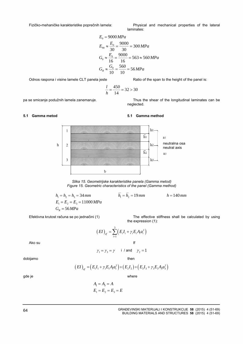
GRAĐEVINSKI MATERIJALI I KONSTRUKCIJE 58 (2015) 4 (51-69) BUILDING MATERIALS AND STRUCTURES 58 (2015) 4 (51-69)
64
Fizičko-mehaničke karakteristike poprečnih lamela: Physical and mechanical properties of the lateral laminates:
0 9000 E MPa=
090
9000 300 30 30EE MPa≈ = =
00
9000 563 560 16 16EG MPa≈ = = ≈
0 560 56 10 10RGG MPa≈ = =
Odnos raspona i visine lamele CLT panela jeste Ratio of the span to the height of the panel is:
450 32 3014
lh
= = >
pa se smicanje podužnih lamela zanemaruje.
5.1 Gamma metod
Thus the shear of the longitudinal laminates can be neglected.
5.1 Gamma method
Slika 15. Geometrijske karakteristike panela (Gamma metod)
Figure 15. Geometric characteristics of the panel (Gamma method)
1 2 3 1 234 19 140 h h h mm h h mm h mm= = = = = = 1 2 3 11000 E E E MPa= = =
56 RG MPa= Efektivna krutost računa se po jednačini (1) The effective stiffness shall be calculated by using
the expression (1):
( ) ( )3
2
1i i i i i ief
i
EI E I E A aγ=
= +∑
Ako su If
1 3γ γ γ= = i / and 2 1γ =
dobijamo then
( ) ( ) ( ) ( )2 21 1 1 1 1 1 2 2 3 3 3 3 3 3ef
EI E I E A a E I E I E A aγ γ= + + + +
gde je where
1 3A A A= =
1 2 3E E E E= = =
neutralna osa neutral axis

GRAĐEVINSKI MATERIJALI I KONSTRUKCIJE 58 (2015) 4 (51-69) BUILDING MATERIALS AND STRUCTURES 58 (2015) 4 (51-69)
65
31
1 2 3 12bhI I I I= = = =
2 0a =
31 2 21 3 1 22 2 2 2
hh h ha a a h h= = = + + = + +
pa se za efektivnu krutost dobija Then the effective stiffness is:
( )223
ef
AaEI EII
γ⎡ ⎤= +⎢ ⎥
⎣ ⎦
Ako je If
( )22
2 2
1 1 0,941811000 1000 34 191 1
4500 56 1000R
EA hl G b
γππ
= = =⋅ ⋅⎡ ⎤
+ ⋅ + ⋅⎢ ⋅⎣ ⎦⋅ ⎥
21000 34 34000 A bh mm= = ⋅ = 31 2 2
1 3 1 234 3419 53
2 2 2 2 2 2hh h ha a a h h mm= = = + + = + + = + + =
3 36 41 1000 34 3,275 10
12 12bhI mm⋅
= = = ×
dobijamo Then
( )2
6 9 26
2 0,9418 34000 5311000 3,275 10 3 2087 10 3,275 10ef
EI Nmm⎡ ⎤⋅ ⋅ ⋅
= ⋅ × + = ×⎢ ⎥×⎣ ⎦
5.2 K - metod (Blass&Fellmoser)
5.2 K - method (Blass&Fellmoser)
Slika 16. Geometrijske karakteristike panela (K-metod)
Figure 16. Geometric characteristics of the panel (K– method)
0 11000 E MPa=
90 300 E MPa=
Iz Tabele 3 dobijamo From Table 3 we get:
5 140 ma a mm= =
2 3 19 34 19 72 ma a mm− = = + + =
4 1 34 ma a mm− = =
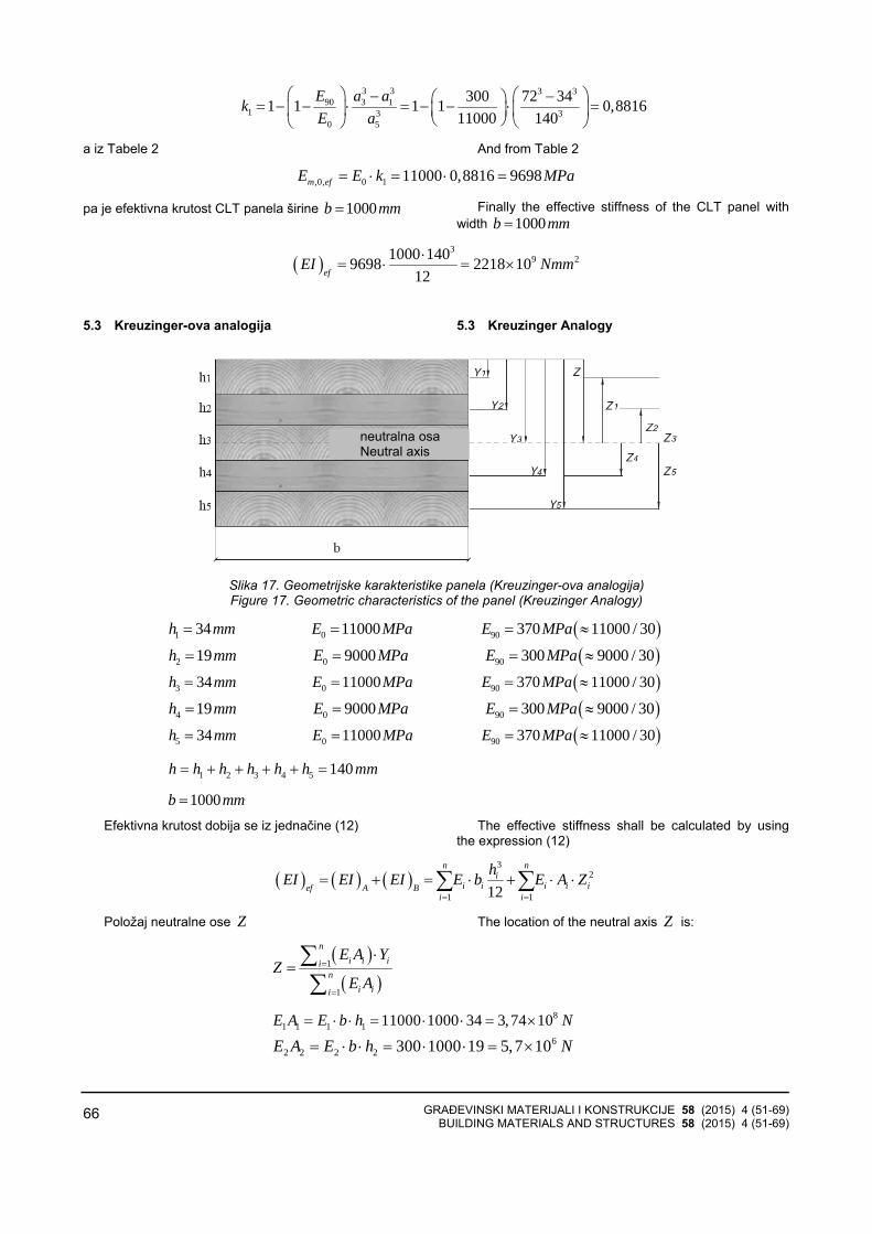
GRAĐEVINSKI MATERIJALI I KONSTRUKCIJE 58 (2015) 4 (51-69) BUILDING MATERIALS AND STRUCTURES 58 (2015) 4 (51-69)
66
3 3 3 390 3 1
1 3 30 5
300 72 341 1 1 1 0,881611000 140
E a akE a
⎛ ⎞ ⎛ ⎞− −⎛ ⎞= − − ⋅ = − − ⋅ =⎜ ⎟ ⎜ ⎟⎜ ⎟⎝ ⎠ ⎝ ⎠⎝ ⎠
a iz Tabele 2 And from Table 2
,0, 0 1 11000 0,8816 9698 m efE E k MPa= = ⋅⋅ =
pa je efektivna krutost CLT panela širine 1000 b mm= Finally the effective stiffness of the CLT panel with width 1000 b mm=
( )3
9 21000 1409698 2218 10 12ef
EI Nmm⋅= ⋅ = ×
5.3 Kreuzinger-ova analogija 5.3 Kreuzinger Analogy
Slika 17. Geometrijske karakteristike panela (Kreuzinger-ova analogija) Figure 17. Geometric characteristics of the panel (Kreuzinger Analogy)
( )1 0 9034 11000 370 11000 / 30h mm E MPa E MPa= = = ≈
( )2 0 9019 9000 300 9000 / 30h mm E MPa E MPa= = = ≈
( )3 0 9034 11000 370 11000 / 30h mm E MPa E MPa= = = ≈
( )4 0 9019 9000 300 9000 / 30h mm E MPa E MPa= = = ≈
( )5 0 9034 11000 370 11000 / 30h mm E MPa E MPa= = = ≈
1 2 3 4 5 140 h h h h h h mm= + + + + =
1000 b mm= Efektivna krutost dobija se iz jednačine (12) The effective stiffness shall be calculated by using
the expression (12)
( ) ( ) ( )3
2
1 112
n ni
i i i i ief A Bi i
hEI EI EI E b E A Z= =
⋅ ⋅ ⋅= + = +∑ ∑
Položaj neutralne ose Z The location of the neutral axis Z is:
( )( )
1
1
ni i ii
ni ii
E A YZ
E A=
=
⋅= ∑
∑
81 1 1 1 11000 1000 34 3,74 10 E A E b h N= ⋅ = ⋅ ⋅ = ×⋅
62 2 2 2 300 1000 19 5,7 10 E A E b h N= ⋅ = ⋅ ⋅ = ×⋅
neutralna osa Neutral axis
GRAĐEVINSKI MATERIJALI I KONSTRUKCIJE 58 (2015) 4 (51-69) BUILDING MATERIALS AND STRUCTURES 58 (2015) 4 (51-69)
67
83 3 3 3 11000 1000 34 3,74 10 E A E b h N= ⋅ = ⋅ ⋅ = ×⋅
64 4 4 4 300 1000 19 5,7 10 E A E b h N= ⋅ = ⋅ ⋅ = ×⋅
85 5 5 5 11000 1000 34 3,74 10 E A E b h N= ⋅ = ⋅ ⋅ = ×⋅
( )5
8
1
11,334 10 i ii
E A N=
= ×∑
11
34 17 2 2hY mm= = =
22 1
1934 43,5 2 2hY h mm= + = + =
33 1 2
3434 19 70 2 2hY h h mm= + + = + + =
44 1 2 3
1934 19 34 96,5 2 2hY h h h mm= + + + = + + + =
55 1 2 3 4
3434 19 34 19 123 2 2hY h h h h mm= + + + + = + + + + =
8 91 1 1 3,74 10 17 6,358 10 E AY Nmm= × = ×⋅
6 82 2 2 5,7 10 43,5 2, 48 10 E A Y Nmm= × = ×⋅
8 103 3 3 3,74 10 70 2,618 10 E A Y Nmm= ×⋅= ×
6 84 4 4 5,7 10 96,5 5,501 10 E A Y Nmm= × = ×⋅
8 105 5 5 3,74 10 123 4,6 10 E A Y Nmm= ×⋅= ×
( )5
10
1
7,934 10 i i ii
E A Y Nmm=
⋅ = ×∑
pa je then
( )( )
510
15 8
1
7,934 10 70 11,334 10
i i ii
i ii
E A YZ mm
E A=
=
⋅ ×= = =
×∑∑
11
3470 53 2 2hZ Z mm= − = − =
22 1
1970 34 26,5 2 2hZ Z h mm= − − = − − =
33 1 2
3470 34 19 0 2 2hZ Z h h mm= − − − = − − − =
4 2 26,5 Z Z mm= − = −
5 1 53 Z Z mm= − = −
Proračun krutosti virtuelne grede A Stiffness calculation for the virtual beam A
( )3
1 12
ni
i iAi
hEI E b=
⋅= ∑
3 310 21
13411000 1000 3,603 10
12 12hE b Nmm= ⋅ = ×

GRAĐEVINSKI MATERIJALI I KONSTRUKCIJE 58 (2015) 4 (51-69) BUILDING MATERIALS AND STRUCTURES 58 (2015) 4 (51-69)
68
3 38 22
219300 1000 1,715 10
12 12hE b Nmm= ⋅ = ×
3 310 23
33411000 1000 3,603 10
12 12hE b Nmm= ⋅ = ×
3 38 24
419300 1000 1,715 10
12 12hE b Nmm= ⋅ = ×
3 310 25
53411000 1000 3,603 10
12 12hE b Nmm= ⋅ = ×
( ) 11 21,084 10 A
EI Nmm= × Proračun krutosti virtuelne grede B Stiffness calculation for the virtual beam B
( ) 2
1
n
i i iBi
EI E A Z=
⋅= ⋅∑
2 2 12 21 1 1 11000 1000 34 53 1,051 10E A Z Nmm= ⋅ ⋅ ⋅ = ×⋅ ⋅
2 2 9 22 2 2 300 1000 19 26,5 4,003 10E A Z Nmm= ⋅ ⋅ ⋅ = ×⋅ ⋅
2 23 3 3 11000 1000 34 0 0 E A Z Nmm= ⋅ ⋅ ⋅ =⋅ ⋅
( )22 9 24 4 4 300 1000 19 26,5 4,003 10E A Z Nmm= ⋅ ⋅ ⋅ − = ×⋅ ⋅
( )22 12 25 5 5 11000 1000 34 53 1,051 10E A Z Nmm= ⋅ ⋅ ⋅ − = ×⋅ ⋅
( ) 12 22,110 10 B
EI Nmm= × Efektivna krutost je Effective stiffness is:
( ) ( ) ( ) 11 12 9 21,084 10 2,110 10 2218 10 ef A B
EI EI EI Nmm= + = × + × = ×
6 ZAKLJUČAK
Primenom CLT u konstrukcijama postiže se zdrav iprirodan ambijent. CLT konstrukcije su čvršće i imajubolje statičke osobine od monolitnog drveta, nemajusklonost ka uvijanju, a pojava napuklina svedena je naminimum. Karakteriše ih velika požarna otpornost, kao i visoka otpornost na potres. Izgradnja CLT konstrukcijebrža je oko 30% nego kada se koristi odgovarajućabetonska konstrukcija, jer se drveni elementi isporučujukao prefabrikovani, koji se zatim brzo uklapaju nagradilištu. Za CLT panele koristi se mekano drvo kojeraste brzo i kog ima u izobilju, pa je i cena CLTkonstrukcija niža od 5 do 10% od odgovarajućihbetonskih ili čeličnih. Drvo je i mnogo bolji izolator - petputa bolji od betona i čak 350 puta bolji od čelika.
6 CONCLUSION
Use of CLT creates healthy and natural ambiance. Compared against traditional wood, CLT construction are stronger, have better mechanical properties, no bending tendency, and minimal fractures appearance. CLT constructions are characterized by high fire resistance, and resilience to earthquakes. Since the elements are delivered prefabricated and can be assembled quickly on the construction site, CLT constructions can be completed roughly 30% faster than comparable concrete projects. Fast growing easily accessible softwood keeps the price of CLT 5 to 10% lower than the competing concrete or steel construction. Timber is 5 times better insulator than concrete and up to 350 times better than steel.
U radu su prikazane analitičke metode proračunakoje se najčešće koriste prilikom dimenzionisanja CLT konstrukcija. Gamma metod daje jednostavan postupakproračuna, ali vrednost efektivne krutosti panela uprikazanom primeru manja je za oko 6% u poređenju sdruge dve metode. Efektivne krutosti panela sračunateK-metodom i Kreuzinger-ovom analogijom imaju istuvrednost, ali je postupak proračuna K-metodom znatnokraći i jednostavniji.
Usvajanjem predloženog međunarodnog standardaEN 16351 Timber structures - Cross laminated timber -Requirements u svim državama Evrope postigao bi sejedinstveni analitički pristup prilikom dimenzionisanja. U
This work presents the most frequently used analytical design methods. Even though Gamma method is a simple design procedure for CLT constructions, result in the shown example for effective stiffness of the panel is about 6% lower compared to other two methods. When calculated using both K-method, and Kreuziner analogy, panels’ effective stiffness values yield same results; however, K-method design procedure is considerably shorter and simpler.
By adopting the international standard EN 16351 Timber Structures – Cross laminated timber –Requirements across all European countries the unified design approach could be achieved. In Serbia the
GRAĐEVINSKI MATERIJALI I KONSTRUKCIJE 58 (2015) 4 (51-69) BUILDING MATERIALS AND STRUCTURES 58 (2015) 4 (51-69)
69
Srbiji, prevod ovog standarda obuhvaćen je planom radaInstituta za standardizaciju Srbije, a njegovo prihvatanjeočekuje se krajem 2015. godine.
proposal of the standard has been made the part of theagenda of the Institute for Standardization and its adoption could be finalized by the end of 2015.
7 LITERATURA REFERENCES
[1] Sylvain Gagnon, M. Mohammad: StructuralPerformance and Design of CLT Building, CLT Symposium and Workshop, Moncton, NB, October12, 2011.
[2] Ian Smith, Andrea Frangi: Use of Timber in TallMulti-Storey Buildings, International Association forBridge and Structural Engineering (IABSE), Zurich,Switzerland, 2014.
[3] Handbook cross-laminated timber, FPInnovationsand Binational Softwood Lumber Council, 2011.
[4] Gerhard Shickhofer: CLT - European Experience, Presentation in the frame of the CLT Forum 2013in Tokyo.
[5] European technical approval ETA-06/0138 Validityfrom 01.07.2011 to 30.06.2016, extends ETA-06/0138 with validity from 27.07.2006 to26.07.2011.
[6] Ben Toosi: Cross Laminated Timber, The MarketOpportunities in North America, FPInnovations,Canada, May 12th 2011.
[7] http://www.drvotehnika.info/clanci/drvo-kao-gradjevinski-materijal-zgrada-od-drveta, 15.03.2015
[8] http://www.woodsolutions.com.au/Inspiration-Case-Study/forte-living, 17.03.2015.
[9] http://www.drvotehnika.info/clanci/drvo-kao-gradjevinski-materijal-zgrada-od-drveta, 15.03.2015.
[10] Sylvain Gagnon: Structural Design of CLT in Canada, Québec City, May, 2010.
[11] Evrokod 5 - Proračun drvenih konstrukcija - Deo 1-1: Opšta pravila i pravila za zgrade, EN 1995-1-1:2004, Beograd, 2009.
[12] Hans Joachim Blass, Peter Fellmoser: Design of solid wood panels with cross layers, Proceedings, 8. World Conference on Timber Engineering, Lahti, Finnland, 2004.
REZIME
UNAKRSNO LAMELIRANI DRVENI ELEMENTI U SAVREMENIM DRVENIM KONSTRUKCIJAMA ZGRADA - primena i proračun
Ljiljana KOZARIĆ Aleksandar PROKIĆ Miroslav BEŠEVIĆ
U radu se analizira unakrsno lamelirano drvo (CLT), moderan građevinski materijal koji se proizvodi odosušenih drvenih elemenata - lamela. Lamele u CLTpanelima su podjednake širine i postavljene su tako davlakna drveta u lamelama po slojevima budumeđusobno pod pravim uglom.
Prikazane su osnovne fizičko-mehaničkekarakteristike CLT panela, kao i analitički modeli koji senajčešće koriste prilikom projektovanja CLT podnih izidnih elemenata u konstrukcijama. Navedene suprednosti i nedostaci ovog novog konstruktivnogsistema, u skladu sa savremenim svetskim zahtevima priprojektovanju modernih, ekološki prihvatljivihkonstrukcija.
Ključne reči: unakrsno lamelirano drvo, savremenedrvene konstrukcije
SUMMARY
CROSS LAMINATED TIMBER ELEMENTS IN CONTEMPORARY TIMBER STRUCTURES OF BUILDINGS - application and design
Ljiljana KOZARIC Aleksandar PROKIC Miroslav BEŠEVIC
This work analyses cross laminated timber (CLT), contemporary building material produced of dried wooden elements - laminates. Laminates in CLT panels are equally wide and timber fibers are rectangularly plated within layers.
Paper shows basic physical - mechanical characteristics of CLT panels and analytic models that are most commonly used in designing of CLT floor and wall construction elements. Advantages and disadvantages of this new construction system are stated according to contemporary requirements in designing environmentally and ecologically acceptable constructions.
Key words: cross laminated timber, contemporary timber structures
GRAĐEVINSKI MATERIJALI I KONSTRUKCIJE 58 (2015) 4 (70-70) BUILDING MATERIALS AND STRUCTURES 58 (2015) 4 (70-70)
70
UPUTSTVO AUTORIMA*
Prihvatanje radova i vrste priloga U časopisu Materijli i konstrukcije štampaće se neobja-
vljeni radovi ili članci i konferencijska saopštenja sa odre-đenim dopunama ili bez dopuna. prema odluci Redakcionog odbora. a samo izuzetno uz dozvolu prethodnog izdavača prihvatiće se i objavljeni rad. Vrste priloga autora i saradnika koji će se štampati su: originalni naučni radovi. prethodna saopštenja. pregledni radovi. stručni radovi. konferencijska saopštenja (radovi sa naučno-stručnih skupova). kao i ostali prilozi kao što su: prikazi objekata i iskustava - primeri. diskusije povodom objavljenih radova i pisma uredništvu. prikazi knjiga i zbornika radova. kao i obaveštenja o naučno-stručnim skupovima.
Originalni naučni rad je primarni izvor naučnih informa-cija i novih ideja i saznanja kao rezultat izvornih istraživanja uz primenu adekvatnih naučnih metoda. Dobijeni rezultati se izlažu kratko. jasno i objektivno. ali tako da poznavalac problema može proceniti rezultate eksperimentalnih ili teorijsko numeričkih analiza i tok razmišljanja. tako da se istraživanje može ponoviti i pri tome dobiti iste ili rezultate u okvirima dopuštenih odstupanja. kako se to u radu navodi.
Prethodno saopštenje sadrži prva kratka obaveštenja o rezultatima istraživanja ali bez podrobnih objašnjenja. tj. kraće je od originalnog naučnog rada. U ovu kategoriju spadaju i diskusije o objavljenim radovima ako one sadrže naučne doprinose.
Pregledni rad je naučni rad koji prikazuje stanje nauke u određenoj oblasti kao plod analize. kritike i komentara i zaključaka publikovanih radova o kojima se daju svi neop-hodni podaci pregledno i kritički uključujući i sopstvene radove. Navode se sve bibliografske jedinice korišćene u obradi tematike. kao i radovi koji mogu doprineti rezultatima daljih istraživanja. Ukoliko su bibliografski podaci metodski sistematizovani. ali ne i analizirani i raspravljeni. takvi pregledni radovi se klasifikuju kao stručni pregledni radovi.
Stručni rad predstavlja koristan prilog u kome se iznose poznate spoznaje koje doprinose širenju znanja i prila-gođavanja rezultata izvornih istraživanja potrebama teorije i prakse. On sadrži i rezultate razvojnih istraživanja.
Konferencijsko saopštenje ili rad sopšten na naučno-stručnom skupu koji mogu biti objavljeni u izvornom obliku ili ih autor. u dogovoru sa redakcijom. bitno preradi i proširi. To mogu biti naučni radovi. naročito ako su sopštenja po pozivu Organizatora skupa ili sadrže originalne rezultate prvi put objavljene. pa ih je korisno uz određene dopune učiniti dostupnim široj stručnoj javnosti. Štampaće se i stručni radovi za koje Redakcioni odbor oceni da su od šireg interesa.
Ostali prilozi su prikazi objekata. tj. njihove konstrukcije i iskustava-primeri u građenju i primeni različitih materijala. diskusije povodom objavljenih radova i pisma uredništvu. prikazi knjiga i zbornika radova. kao i obaveštenja o naučno-stručnim skupovima.
Autori uz rukopis predlažu kategorizaciju članka. Svi radovi pre objavljivanja se recenziraju. a o prihvatanju za publikovanje o njihovoj kategoriji konačnu odluku donosi Redakcioni odbor.
Da bi se ubrzao postupak prihvatanja radova za publikovanje. potrebno je da autori uvažavaju Uputstva za pripremu radova koja su navedena u daljem tekstu.
Uputstva za pripremu rukopisa
Rukopis otkucati jednostrano na listovima A-4 sa marginama od 31 mm (gore i dole) a 20 mm (levo i desno). u Wordu fontom Arial sa 12 pt. Potrebno je uz jednu kopiju svih delova rada i priloga. dostaviti i elektronsku verziju na navedene E-mail adrese. ili na CD-u. Autor je obavezan da čuva jednu kopiju rukopisa kod sebe zbog eventualnog oštećenja ili gubitka rukopisa.
Od broja 1/2010. prema odluci Upravnog odbora Društva i Redakcionog odbora. radovi sa pozitivnim recenzijama i prihvaćeni za štampu. publikovaće se na srpskom i engleskom jeziku.
* Uputstvo autorima je modifikovano i treba ga u pripremi
radova slediti.
Svaka stranica treba da bude numerisana. a optimalni obim članka na jednom jeziku. je oko 16 stranica (30000 slovnih mesta) uključujući slike. fotografije. tabele i popis literature. Za radove većeg obima potrebna je saglasnost Redakcionog odbora.
Naslov rada treba sa što manje reči (poželjno osam. a najviše do jedanaeset) da opiše sadržaj članka. U naslovu ne koristiti skraćenice ni formule. U radu se iza naslova daju ime i prezime autora. a titule i zvanja. kao iime institucije u podnožnoj napomeni. Autor za kontakt daje telefone. faks i adresu elektronske pošte. a za ostale autore poštansku adresu.
Uz sažetak (rezime) od oko 150 do 200 reči. na srpskom i engleskom jeziku daju se ključne reči (do deset). To je jezgrovit prikaz celog članka i čitaocima omogućuje uvid u njegove bitne elemente.
Rukopis se deli na poglavlja i potpoglovlja uz numera-ciju. po hijerarhiji. arapskim brojevima. Svaki rad ima uvod. sadržinu rada sa rezultatima. analizom i zaključcima. Na kraju rada se daje popis literature.
Kod svih dimenzionalnih veličina obavezna je primena međunarodnih SI mernih jedinica.
Formule i jednačine treba pisati pažljivo vodeći računa o indeksima i eksponentima. Autori uz izraze u tekstu definšu simbole redom kako se pojavljuju. ali se može dati i posebna lista simbola u prilogu.
Prilozi (tabele. grafikoni. sheme i fotografije) rade se u crno-beloj tehnici. u formatu koji obezbeđuje da pri smanjenju na razmere za štampu. po širini jedan do dva stupca (8cm ili 16.5cm). a po visini najviše 24.5cm. ostanu jasni i čitljivi. tj. da veličine slova i brojeva budu najmanje 1.5mm. Originalni crteži treba da budu kvalitetni i u potpunosti pripremljeni za presnimavanje. Mogu biti i dobre. oštre i kontrastne fotokopije. Koristiti fotogrfije. u crno-beloj tehnici. na kvalitetnoj hartiji sa oštrim konturama. koje omogućuju jasnu reprodukciju. Skraćenice u prilozima koristiti samo izuzetno uz obaveznu legendu. Prilozi se posebno označavaju arapskim brojevima. prema redosledu navođenja u tekstu. Objašnjenje tabela daje se u tekstu.
Potrebno je dati spisak svih skraćenica korišćenih u tekstu.
U popisu literature na kraju rada daju se samo oni radovi koji se pominju u tekstu. Citirane radove treba prikazati po azbučnom redu prezimena prvog autora. Literaturu u tekstu označiti arapskim brojevima u uglastim zagradama. kako se navodi i u Popisu citirane literature. napr [1]. Svaki citat u tekstu mora se naći u Popisu citirane literature i obrnuto svaki podatak iz Popisa se mora navesti u tekstu.
U Popisu literature se navode prezime i inicijali imena autora. zatim potpuni naslov citiranog članka. iza toga sledi ime časopisa. godina izdavanja i početna i završna stranica (od - do). Za knjige iza naslova upisuje se ime urednika (ako ih ima). broj izdanja. prva i poslednja stranicapoglavlja ili dela knjige. ime izdavača i mesto objavljivanja. ako je navedeno više gradova navodi se samo prvi po redu. Kada autor citirane podatke ne uzima iz izvornog rada. već ih je pronašao u drugom delu. uz citat se dodaje «citirano prema...». Neobjavljeni članci mogu se pominjati u tekstu kao «usmeno saopštenje»
Autori su odgovorni za izneseni sadržaj i moraju sami obezbediti eventualno potrebne saglasnosti za objavljivanje nekih podataka i priloga koji se koriste u radu.
Ukoliko rad bude prihvaćen za štampu. autori su dužni da. po uputstvu Redakcije. unesu sve ispravke i dopune u tekstu i prilozima. Za detaljnija tehnička uputstva za pripremu rukopisa autori se mogu obratiti Redakcionom odboru časopisa.
Rukopisi i prilozi objavljenih radova se ne vraćaju. Sva eventualna objašnjenja i uputstva mogu se dobiti od Redakcionog odbora.
Radovi se mogu slati i na e-mail: [email protected] ili [email protected] i [email protected]
Veb sajt Društva i časopisa: www.dimk.rs

GRAĐEVINSKI MATERIJALI I KONSTRUKCIJE 58 (2015) 4 (71-71) BUILDING MATERIALS AND STRUCTURES 58 (2015) 4 (71-71)
71
Izdavanje časopisa "Građevinski materijali i konstrukcije" finansijski su pomogli:
.
INŽENJERSKA KOMORA SRBIJE REPUBLIKA SRBIJA MINISTARSTVO PROSVETE, NAUKE I TEHNOLOŠKOG RAZVOJA UNIVERZITET U BEOGRADU GRAĐEVINSKI FAKULTET
DEPARTMAN ZA GRAĐEVINARSTVO I GEODEZIJU FAKULTET TEHNIČKIH NAUKA NOVI SAD INSTITUT IMS AD, BEOGRAD
UNIVERZITET CRNE GORE GRAĐEVINSKI FAKULTET - PODGORICA
departman za građevinarstvo