grade crossing control systems productsa45ee7cb-389b... · nyk:80008045500000 nyk:811080455002ac...
TRANSCRIPT
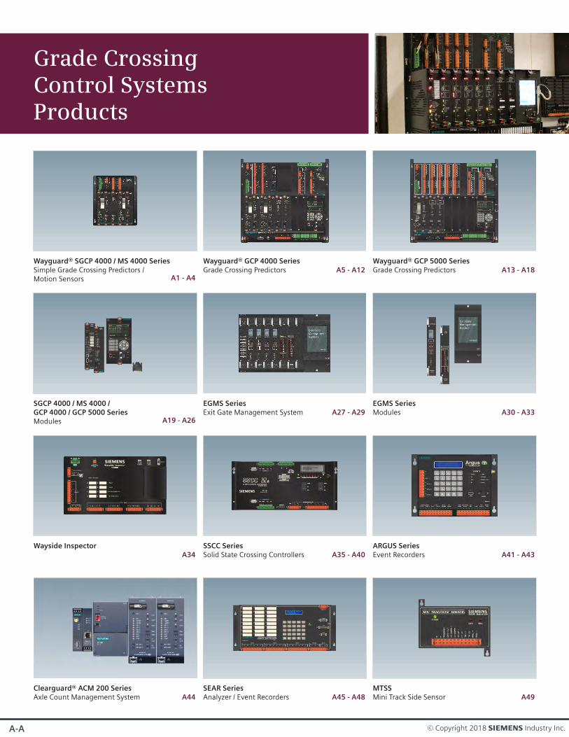
Grade Crossing Control SystemsProducts
© Copyright 2018 s Industry Inc.A-A
Wayguard® SGCP 4000 / MS 4000 SeriesSimple Grade Crossing Predictors / Motion Sensors A1 - A4
Wayguard® GCP 4000 SeriesGrade Crossing Predictors A5 - A12
SGCP 4000 / MS 4000 /GCP 4000 / GCP 5000 SeriesModules A19 - A26
EGMS SeriesExit Gate Management System
ARGUS SeriesEvent Recorders A41 - A43
A27 - A29
SEAR SeriesAnalyzer / Event Recorders A45 - A48
Wayguard® GCP 5000 SeriesGrade Crossing Predictors A13 - A18
Wayside InspectorA34
SSCC SeriesSolid State Crossing Controllers A35 - A40
MTSSMini Track Side Sensor A49
Clearguard® ACM 200 SeriesAxle Count Management System A44
EGMS SeriesModules A30 - A33
A-BSIE-RA-CMP-001-18-EN
GFT II SeriesGround Fault Sensors A51 - A52
iLODIntelligent Lights Out Detector
A50
Gra
de
Cro
ssin
g S
yst
em
sG
rad
e C
ross
ing
Co
ntr
ol
Sy
ste
ms
Pro
du
cts
A1 © Copyright 2018 s Industry Inc.
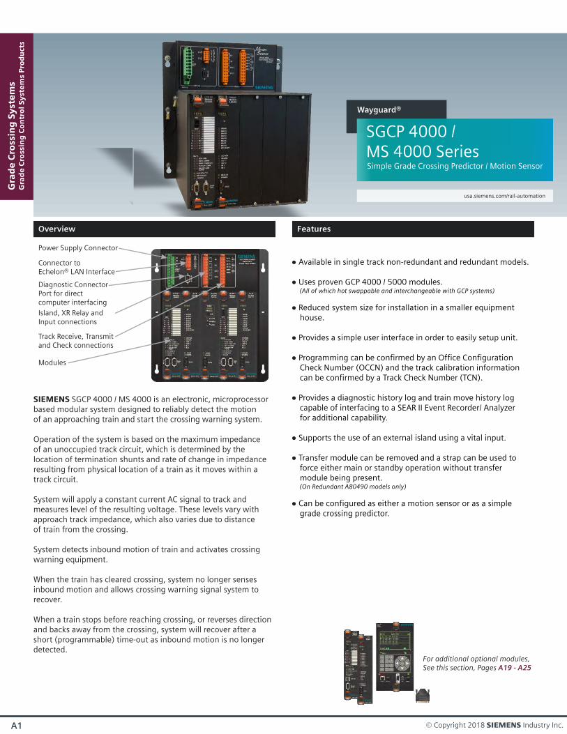
Power Supply Connector
Diagnostic ConnectorPort for directcomputer interfacing
Connector toEchelon® LAN Interface
Track Receive, Transmitand Check connections
Island, XR Relay andInput connections
Modules
For additional optional modules, See this section, Pages A19 - A25
SIEMENS SGCP 4000 / MS 4000 is an electronic, microprocessorbased modular system designed to reliably detect the motion of an approaching train and start the crossing warning system.
Operation of the system is based on the maximum impedance of an unoccupied track circuit, which is determined by the location of termination shunts and rate of change in impedance resulting from physical location of a train as it moves within atrack circuit.
System will apply a constant current AC signal to track and measures level of the resulting voltage. These levels vary with approach track impedance, which also varies due to distance of train from the crossing.
System detects inbound motion of train and activates crossing warning equipment.
When the train has cleared crossing, system no longer senses inbound motion and allows crossing warning signal system to recover.
When a train stops before reaching crossing, or reverses direction and backs away from the crossing, system will recover after a short (programmable) time-out as inbound motion is no longer detected.
Available in single track non-redundant and redundant models.
Uses proven GCP 4000 / 5000 modules. (All of which hot swappable and interchangeable with GCP systems)
Reduced system size for installation in a smaller equipment house.
Provides a simple user interface in order to easily setup unit.
Programming can be confirmed by an Office Configuration Check Number (OCCN) and the track calibration information can be confirmed by a Track Check Number (TCN).
Provides a diagnostic history log and train move history log capable of interfacing to a SEAR II Event Recorder/ Analyzer for additional capability.
Supports the use of an external island using a vital input.
Transfer module can be removed and a strap can be used to force either main or standby operation without transfer module being present. (On Redundant A80490 models only)
Can be configured as either a motion sensor or as a simple grade crossing predictor.
usa.siemens.com/rail-automation
SGCP 4000 / MS 4000 SeriesSimple Grade Crossing Predictor / Motion Sensor
Wayguard®
Overview
Features
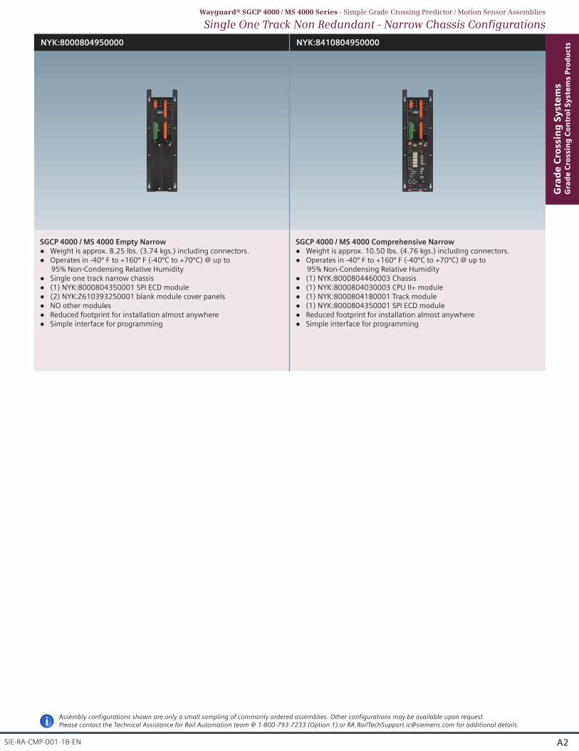
SGCP 4000 / MS 4000 Empty Narrow Weight is approx. 8.25 lbs. (3.74 kgs.) including connectors. Operates in -40º F to +160º F (-40ºC to +70ºC) @ up to
95% Non-Condensing Relative Humidity Single one track narrow chassis (1) NYK:8000804350001 SPI ECD module (2) NYK:Z610393250001 blank module cover panels NO other modules Reduced footprint for installation almost anywhere Simple interface for programming
SGCP 4000 / MS 4000 Comprehensive Narrow Weight is approx. 10.50 lbs. (4.76 kgs.) including connectors. Operates in -40º F to +160º F (-40ºC to +70ºC) @ up to
95% Non-Condensing Relative Humidity (1) NYK:8000804460003 Chassis (1) NYK:8000804030003 CPU II+ module (1) NYK:8000804180001 Track module (1) NYK:8000804350001 SPI ECD module Reduced footprint for installation almost anywhere Simple interface for programming
A2
Gra
de
Cro
ssin
g S
yst
em
sG
rad
e C
ross
ing
Co
ntr
ol
Sy
ste
ms
Pro
du
cts
SIE-RA-CMP-001-18-EN
NYK:8000804950000 NYK:8410804950000
Single One Track Non Redundant - Narrow Chassis ConfigurationsWayguard® SGCP 4000 / MS 4000 Series - Simple Grade Crossing Predictor / Motion Sensor Assemblies
iAssembly configurations shown are only a small sampling of commonly ordered assemblies. Other configurations may be available upon request. Please contact the Technical Assistance for Rail Automation team @ 1-800-793-7233 (Option 1) or [email protected] for additional details.
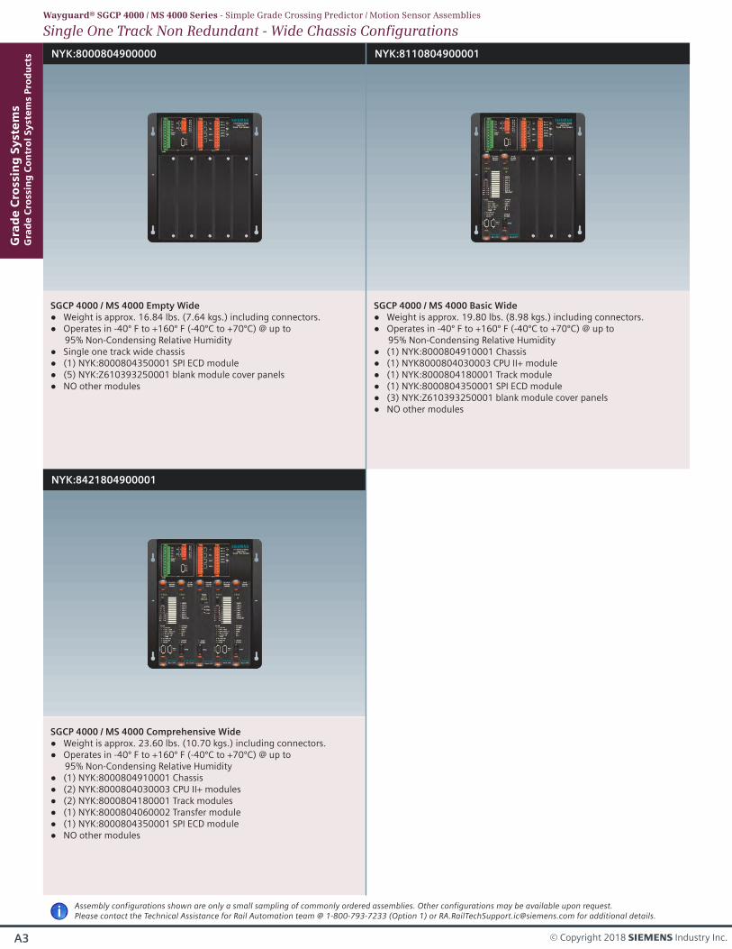
NYK:8000804900000 NYK:8110804900001
NYK:8421804900001
SGCP 4000 / MS 4000 Empty Wide Weight is approx. 16.84 lbs. (7.64 kgs.) including connectors. Operates in -40º F to +160º F (-40ºC to +70ºC) @ up to
95% Non-Condensing Relative Humidity Single one track wide chassis (1) NYK:8000804350001 SPI ECD module (5) NYK:Z610393250001 blank module cover panels NO other modules
SGCP 4000 / MS 4000 Basic Wide Weight is approx. 19.80 lbs. (8.98 kgs.) including connectors. Operates in -40º F to +160º F (-40ºC to +70ºC) @ up to
95% Non-Condensing Relative Humidity (1) NYK:8000804910001 Chassis (1) NYK8000804030003 CPU II+ module (1) NYK:8000804180001 Track module (1) NYK:8000804350001 SPI ECD module (3) NYK:Z610393250001 blank module cover panels NO other modules
SGCP 4000 / MS 4000 Comprehensive Wide Weight is approx. 23.60 lbs. (10.70 kgs.) including connectors. Operates in -40º F to +160º F (-40ºC to +70ºC) @ up to
95% Non-Condensing Relative Humidity (1) NYK:8000804910001 Chassis (2) NYK:8000804030003 CPU II+ modules (2) NYK:8000804180001 Track modules (1) NYK:8000804060002 Transfer module (1) NYK:8000804350001 SPI ECD module NO other modules
Gra
de
Cro
ssin
g S
yst
em
sG
rad
e C
ross
ing
Co
ntr
ol
Sy
ste
ms
Pro
du
cts
A3 © Copyright 2018 s Industry Inc.
Single One Track Non Redundant - Wide Chassis ConfigurationsWayguard® SGCP 4000 / MS 4000 Series - Simple Grade Crossing Predictor / Motion Sensor Assemblies
iAssembly configurations shown are only a small sampling of commonly ordered assemblies. Other configurations may be available upon request. Please contact the Technical Assistance for Rail Automation team @ 1-800-793-7233 (Option 1) or [email protected] for additional details.
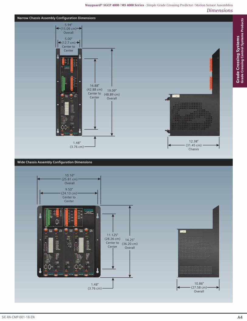
Narrow Chassis Assembly Configuration Dimensions
5.94”(15.09 cm)
Overall
12.38”(31.45 cm)
Chassis
A4
Gra
de
Cro
ssin
g S
yst
em
sG
rad
e C
ross
ing
Co
ntr
ol
Sy
ste
ms
Pro
du
cts
SIE-RA-CMP-001-18-EN
14.25”(36.20 cm)
Overall
10.16”(25.81 cm)
Overall
10.86”(27.58 cm)
Overall
DimensionsWayguard® SGCP 4000 / MS 4000 Series - Simple Grade Crossing Predictor / Motion Sensor Assemblies
Wide Chassis Assembly Configuration Dimensions
1.48”(3.76 cm)
11.125”(28.26 cm)Center to
Center
5.00”(12.7 cm)Center to
Center
9.50”(24.13 cm)Center to
Center
19.09”(48.89 cm)
Overall
1.48”(3.76 cm)
16.88”(42.88 cm)Center to
Center
Capable of monitoring up to (6) track circuits including Intelligent Processor Island and Bi-DAXing. (Number of maximum track modules dependent on chasis of GCP system selected.) (On redundant systems, (2) track modules needed for each track circuit.)
SEAR IIi Event Analyzer / Recorder programmable via OCE and new display.
Provides a diagnostic history log and train move history log utilizing a SEAR IIi Event Recorder/ Analyzer.
Internal logic utilizing vital AND gates and vital timers.
Multiple ethernet ports available for interfacing with eSSR radio, vital communications as well as PTC applications. (Depending on configuration, some ports may not be activated.) Enhanced user interface tools including OCE, WebUI and new display.
Common menu structure between all user interfaces.
Generate office configuration check number (OCCN).
Simple, tailored dropdown menus for user friendly configuration, diagnostics and troubleshooting.
A5 © Copyright 2018 s Industry Inc.
Gra
de
Cro
ssin
g S
yst
em
sG
rad
e C
ross
ing
Co
ntr
ol
Sy
ste
ms
Pro
du
cts
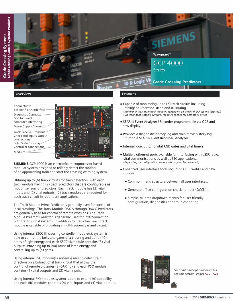
GCP 4000Series
Wayguard®
Grade Crossing Predictors
Power Supply Connector
Diagnostic ConnectorPort for directcomputer interfacing
Connector toEchelon® LAN Interface
Track Receive, TransmitCheck and Input / Outputconnections
Modules
Solid State CrossingController connections
For additional optional modules, See this section, Pages A19 - A25
SIEMENS GCP 4000 is an electronic, microprocessor based modular system designed to reliably detect the motion of an approaching train and start the crossing warning system.
Utilizing up to (6) track circuits for train detection, with each track module having (9) track predictors that are configurable as motion sensors or predictors. Each track module has (2) vital inputs and (2) vital outputs. (2) track modules are required for each track circuit in redundant applications.
The Track Module Prime Predictor is generally used for control of local crossings. The Track Module DAX A through DAX G Predictors are generally used for control of remote crossings. The Track Module Preempt Predictor is generally used for interconnection with traffic signal systems. In addition to predictors, each track module is capable of providing a multifrequency island circuit.
Using internal SSCC IIIi crossing controller module(s), system is able to control the bells and gates of a crossing and up to (40) amps of light energy and each SSCC IIIi module contains (5) vital outputs. Providing up to (40) amps of lamp energy and controlling up to (4) gates.
Using internal PSO module(s) system is able to detect train direction on a bidirectional track circuit that allows the control of remote crossings (Bi-DAXing) and each PSO module contains (3) vital outputs and (2) vital inputs.
Using internal RIO modules system is able to extend I/O capabilityand each RIO modules contains (4) vital inputs and (4) vital outputs.
Overview
Features
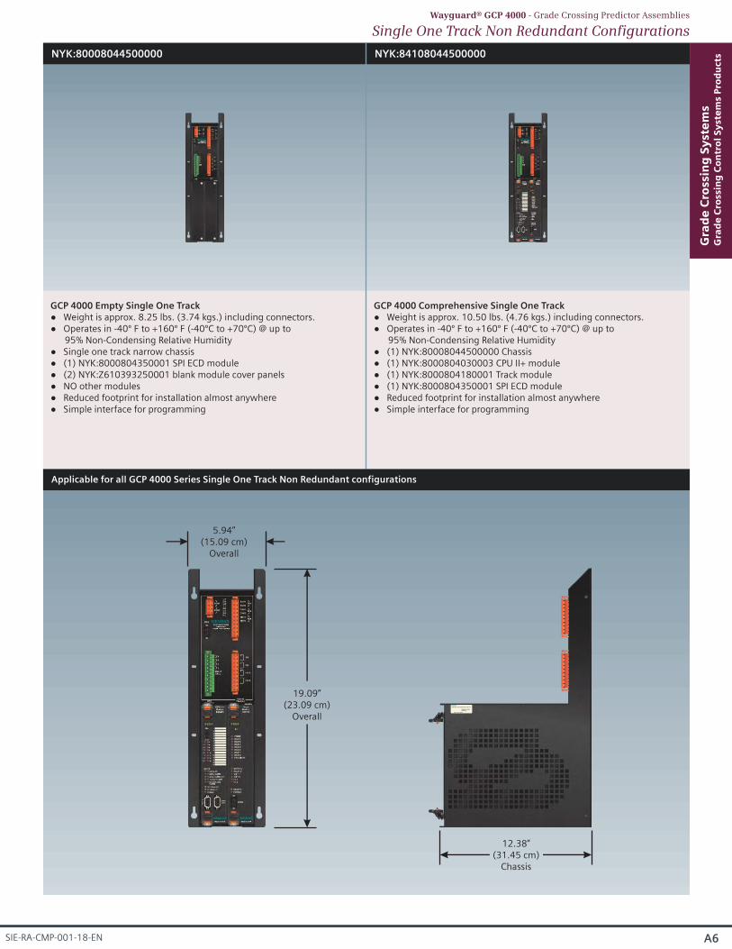
NYK:80008044500000 NYK:84108044500000
GCP 4000 Empty Single One Track Weight is approx. 8.25 lbs. (3.74 kgs.) including connectors. Operates in -40º F to +160º F (-40ºC to +70ºC) @ up to
95% Non-Condensing Relative Humidity Single one track narrow chassis (1) NYK:8000804350001 SPI ECD module (2) NYK:Z610393250001 blank module cover panels NO other modules Reduced footprint for installation almost anywhere Simple interface for programming
GCP 4000 Comprehensive Single One Track Weight is approx. 10.50 lbs. (4.76 kgs.) including connectors. Operates in -40º F to +160º F (-40ºC to +70ºC) @ up to
95% Non-Condensing Relative Humidity (1) NYK:80008044500000 Chassis (1) NYK:8000804030003 CPU II+ module (1) NYK:8000804180001 Track module (1) NYK:8000804350001 SPI ECD module Reduced footprint for installation almost anywhere Simple interface for programming
A6
Gra
de
Cro
ssin
g S
yst
em
sG
rad
e C
ross
ing
Co
ntr
ol
Sy
ste
ms
Pro
du
cts
SIE-RA-CMP-001-18-EN
Single One Track Non Redundant ConfigurationsWayguard® GCP 4000 - Grade Crossing Predictor Assemblies
19.09”(23.09 cm)
Overall
5.94”(15.09 cm)
Overall
12.38”(31.45 cm)
Chassis
Applicable for all GCP 4000 Series Single One Track Non Redundant configurations

NYK:80008044000000
GCP 4000 Empty Single Five Track Weight is approx. 26.01 lbs. (11.80 kgs.) including connectors. Operates in -40º F to +160º F (-40ºC to +70ºC) @ up to
95% Non-Condensing Relative Humidity Single five track chassis (1) NYK:8000804350001 SPI ECD module (8) NYK:Z610393250001 blank module cover panels (1) NYK:Z610393260001 blank display cover panel (1) NYK:Z610393590001 blank SEAR cover panel NO other modules
NYK:811080440002J3
GCP 4000 Comprehensive Single Five Track Weight is approx. 48.60 lbs. (22.04 kgs.) including connectors. Operates in -40º F to +160º F (-40ºC to +70ºC) @ up to
95% Non-Condensing Relative Humidity (1) NYK:80008044000000 Chassis (1) NYK:8000804030001 CPU II+ module (1) NYK:8000804180001 Track module (1) NYK:8000804850001 Display module (1) NYK:8000804100001 SEAR IIi module (2) NYK:8000804050001 SSCC IIIi modules (1) NYK:8000804350001 SPI ECD module (4) NYK:Z610393250001 blank module cover panels NO other modules
Gra
de
Cro
ssin
g S
yst
em
sG
rad
e C
ross
ing
Co
ntr
ol
Sy
ste
ms
Pro
du
cts
A7 © Copyright 2018 s Industry Inc.
Single Five Track Non Redundant ConfigurationsWayguard® GCP 4000 - Grade Crossing Predictor Assemblies
Applicable for all GCP 4000 Series Single Five Track Non Redundant configurations
22.15”(56.26 cm)
Overall
23.25”(59.06 cm)
Overall
12.38”(31.45 cm)
Chassis
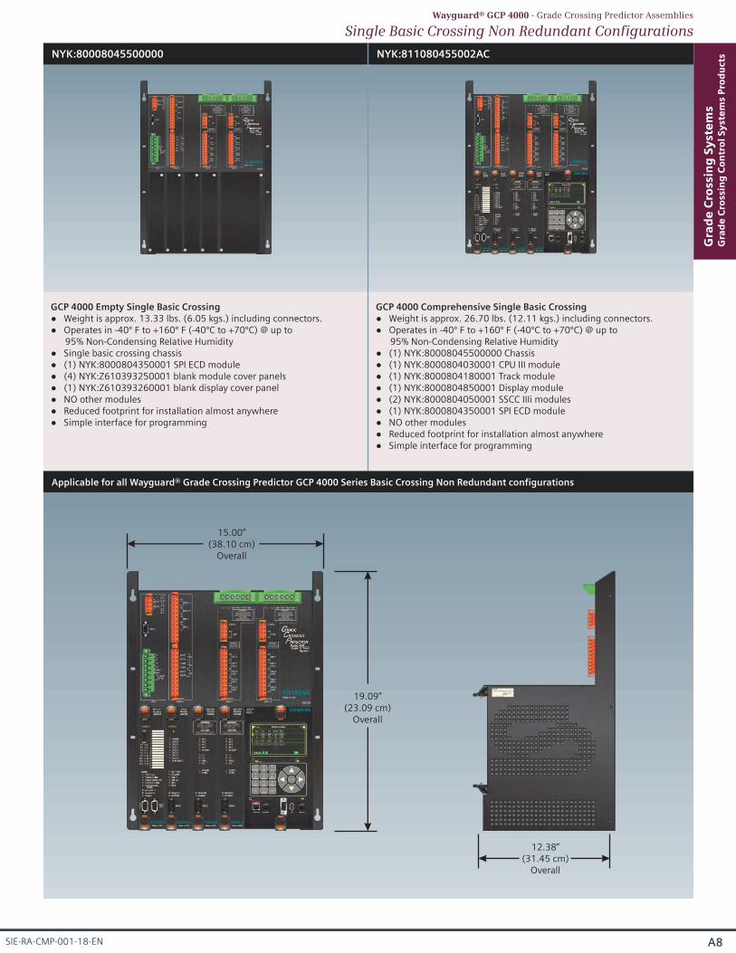
NYK:80008045500000 NYK:811080455002AC
GCP 4000 Empty Single Basic CrossingWeight is approx. 13.33 lbs. (6.05 kgs.) including connectors.Operates in -40º F to +160º F (-40ºC to +70ºC) @ up to 95% Non-Condensing Relative HumiditySingle basic crossing chassis(1) NYK:8000804350001 SPI ECD module(4) NYK:Z610393250001 blank module cover panels(1) NYK:Z610393260001 blank display cover panelNO other modules
Reduced footprint for installation almost anywhereSimple interface for programming
GCP 4000 Comprehensive Single Basic CrossingWeight is approx. 26.70 lbs. (12.11 kgs.) including connectors.Operates in -40º F to +160º F (-40ºC to +70ºC) @ up to 95% Non-Condensing Relative Humidity(1) NYK:80008045500000 Chassis(1) NYK:8000804030001 CPU III module(1) NYK:8000804180001 Track module(1) NYK:8000804850001 Display module(2) NYK:8000804050001 SSCC IIIi modules(1) NYK:8000804350001 SPI ECD moduleNO other modulesReduced footprint for installation almost anywhereSimple interface for programming
Single Basic Crossing Non Redundant ConfigurationsWayguard® GCP 4000 - Grade Crossing Predictor Assemblies
Applicable for all Wayguard® Grade Crossing Predictor GCP 4000 Series Basic Crossing Non Redundant configurations
19.09”(23.09 cm)
Overall
15.00”(38.10 cm)
Overall
12.38”(31.45 cm)
Overall
A8
Gra
de
Cro
ssin
g S
yst
em
sG
rad
e C
ross
ing
Co
ntr
ol
Sy
ste
ms
Pro
du
cts
SIE-RA-CMP-001-18-EN

NYK:80008046500000
GCP 4000 Empty Dual Two Track Weight is approx. 25.73 lbs. (11.67 kgs.) including connectors. Operates in -40º F to +160º F (-40ºC to +70ºC) @ up to
95% Non-Condensing Relative Humidity Dual two track chassis (1) NYK:8000804350001 SPI ECD module (8) NYK:Z610393250001 blank module cover panels (1) NYK:Z610393260001 blank display cover panel (1) NYK:Z610393590001 blank SEAR cover panel NO other modules Built in DAXing, ATCS communications protocols
NYK:822080465002W3
GCP 4000 Comprehensive Dual Two Track Weight is approx. 50.10 lbs. (22.73 kgs.) including connectors. Operates in -40º F to +160º F (-40ºC to +70ºC) @ up to
95% Non-Condensing Relative Humidity (1) NYK:80008044000000 Chassis (2) NYK:8000804030001 CPU II+ module (2) NYK:8000804180001 Track module (1) NYK:8000804850001 Display module (1) NYK:8000804100001 SEAR IIi module (2) NYK:8000804050001 SSCC IIIi modules (1) NYK:8000804680001 Transfer module (1) NYK:8000804350001 SPI ECD module (2) NYK:Z610393250001 blank module cover panels NO other modules Built in DAXing, ATCS communications protocols
Gra
de
Cro
ssin
g S
yst
em
sG
rad
e C
ross
ing
Co
ntr
ol
Sy
ste
ms
Pro
du
cts
A9 © Copyright 2018 s Industry Inc.
Dual Two Track Redundant ConfigurationsWayguard® GCP 4000 - Grade Crossing Predictor Assemblies
Applicable for all Wayguard® Grade Crossing Predictor GCP 4000 Series Dual Two Track Redundant configurations
22.15”(56.26 cm)
Overall
23.25”(59.06 cm)
Overall
12.38”(31.45 cm)
Overall
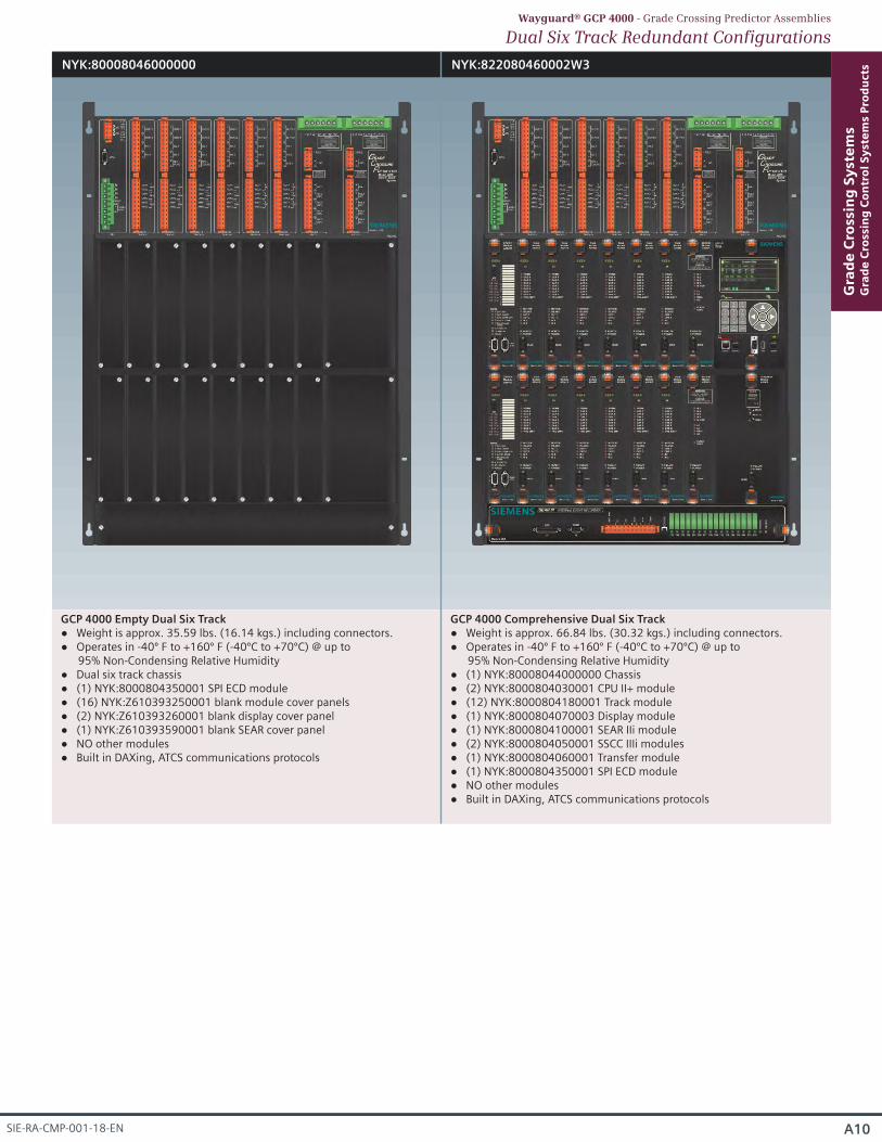
NYK:80008046000000 NYK:822080460002W3
GCP 4000 Empty Dual Six Track Weight is approx. 35.59 lbs. (16.14 kgs.) including connectors. Operates in -40º F to +160º F (-40ºC to +70ºC) @ up to
95% Non-Condensing Relative Humidity Dual six track chassis (1) NYK:8000804350001 SPI ECD module (16) NYK:Z610393250001 blank module cover panels (2) NYK:Z610393260001 blank display cover panel (1) NYK:Z610393590001 blank SEAR cover panel NO other modules Built in DAXing, ATCS communications protocols
GCP 4000 Comprehensive Dual Six Track Weight is approx. 66.84 lbs. (30.32 kgs.) including connectors. Operates in -40º F to +160º F (-40ºC to +70ºC) @ up to
95% Non-Condensing Relative Humidity (1) NYK:80008044000000 Chassis (2) NYK:8000804030001 CPU II+ module (12) NYK:8000804180001 Track module (1) NYK:8000804070003 Display module (1) NYK:8000804100001 SEAR IIi module (2) NYK:8000804050001 SSCC IIIi modules (1) NYK:8000804060001 Transfer module (1) NYK:8000804350001 SPI ECD module NO other modules Built in DAXing, ATCS communications protocols
Dual Six Track Redundant ConfigurationsWayguard® GCP 4000 - Grade Crossing Predictor Assemblies
A10
Gra
de
Cro
ssin
g S
yst
em
sG
rad
e C
ross
ing
Co
ntr
ol
Sy
ste
ms
Pro
du
cts
SIE-RA-CMP-001-18-EN
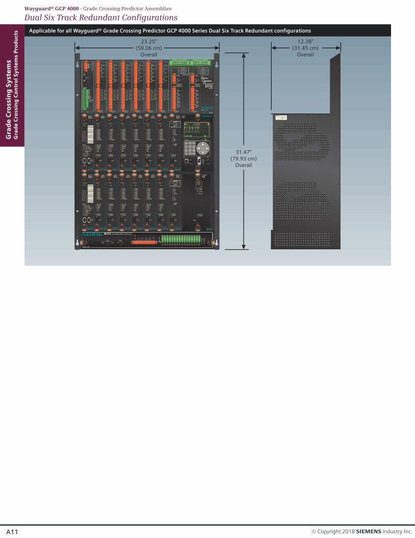
Applicable for all Wayguard® Grade Crossing Predictor GCP 4000 Series Dual Six Track Redundant configurations
31.47”(79.93 cm)
Overall
23.25”(59.06 cm)
Overall
12.38”(31.45 cm)
Overall
Gra
de
Cro
ssin
g S
yst
em
sG
rad
e C
ross
ing
Co
ntr
ol
Sy
ste
ms
Pro
du
cts
A11 © Copyright 2018 s Industry Inc.
Dual Six Track Redundant ConfigurationsWayguard® GCP 4000 - Grade Crossing Predictor Assemblies

A12
Gra
de
Cro
ssin
g S
yst
em
sG
rad
e C
ross
ing
Co
ntr
ol
Sy
ste
ms
Pro
du
cts
SIE-RA-CMP-001-18-EN
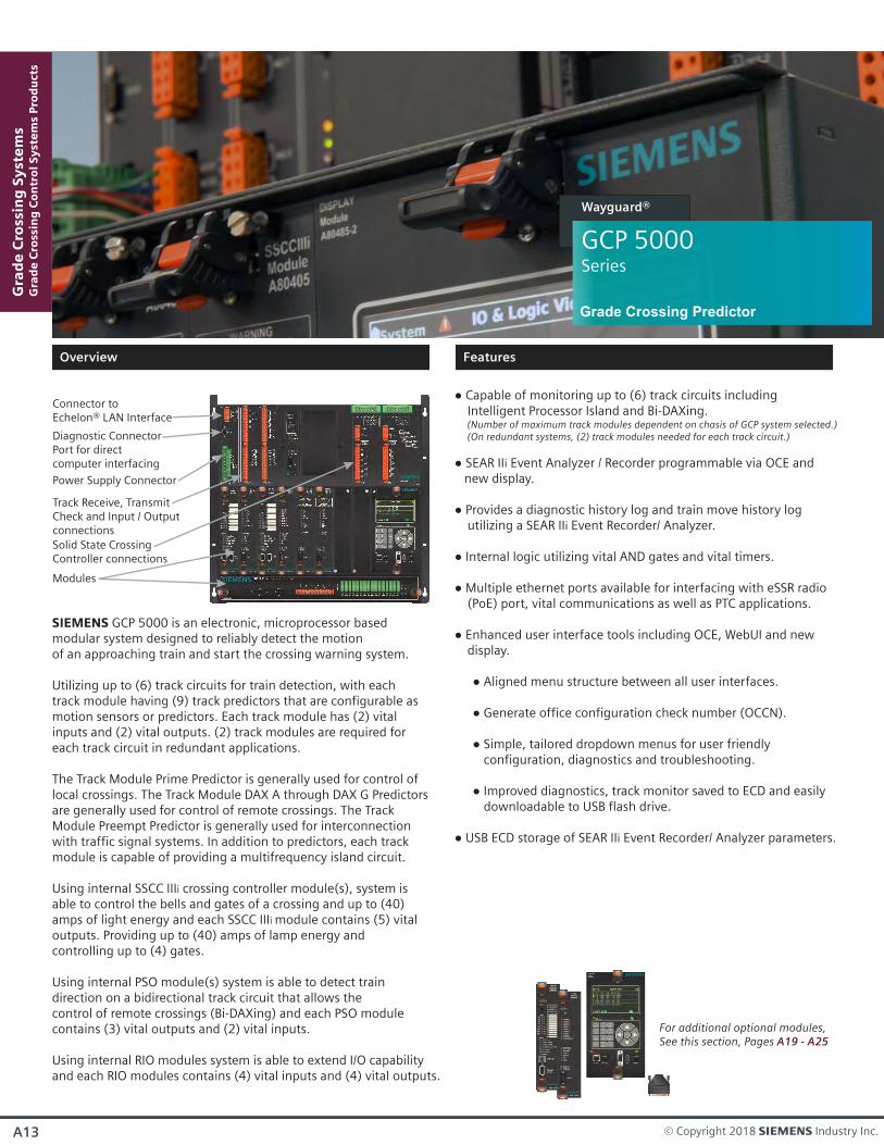
Capable of monitoring up to (6) track circuits including Intelligent Processor Island and Bi-DAXing. (Number of maximum track modules dependent on chasis of GCP system selected.) (On redundant systems, (2) track modules needed for each track circuit.)
SEAR IIi Event Analyzer / Recorder programmable via OCE and new display.
Provides a diagnostic history log and train move history log utilizing a SEAR IIi Event Recorder/ Analyzer.
Internal logic utilizing vital AND gates and vital timers.
Multiple ethernet ports available for interfacing with eSSR radio (PoE) port, vital communications as well as PTC applications. Enhanced user interface tools including OCE, WebUI and new display.
Aligned menu structure between all user interfaces.
Generate office configuration check number (OCCN).
Simple, tailored dropdown menus for user friendly configuration, diagnostics and troubleshooting.
Improved diagnostics, track monitor saved to ECD and easily downloadable to USB flash drive.
USB ECD storage of SEAR IIi Event Recorder/ Analyzer parameters.
Power Supply Connector
Diagnostic ConnectorPort for directcomputer interfacing
Connector toEchelon® LAN Interface
Track Receive, TransmitCheck and Input / Outputconnections
Modules
Solid State CrossingController connections
For additional optional modules, See this section, Pages A19 - A25
SIEMENS GCP 5000 is an electronic, microprocessor based modular system designed to reliably detect the motion of an approaching train and start the crossing warning system.
Utilizing up to (6) track circuits for train detection, with each track module having (9) track predictors that are configurable as motion sensors or predictors. Each track module has (2) vital inputs and (2) vital outputs. (2) track modules are required for each track circuit in redundant applications.
The Track Module Prime Predictor is generally used for control of local crossings. The Track Module DAX A through DAX G Predictors are generally used for control of remote crossings. The Track Module Preempt Predictor is generally used for interconnection with traffic signal systems. In addition to predictors, each track module is capable of providing a multifrequency island circuit.
Using internal SSCC IIIi crossing controller module(s), system is able to control the bells and gates of a crossing and up to (40) amps of light energy and each SSCC IIIi module contains (5) vital outputs. Providing up to (40) amps of lamp energy and controlling up to (4) gates.
Using internal PSO module(s) system is able to detect train direction on a bidirectional track circuit that allows the control of remote crossings (Bi-DAXing) and each PSO module contains (3) vital outputs and (2) vital inputs.
Using internal RIO modules system is able to extend I/O capabilityand each RIO modules contains (4) vital inputs and (4) vital outputs.
GCP 5000Series
Wayguard®
Grade Crossing Predictor
Overview
Features
Gra
de
Cro
ssin
g S
yst
em
sG
rad
e C
ross
ing
Co
ntr
ol
Sy
ste
ms
Pro
du
cts
A13 © Copyright 2018 s Industry Inc.
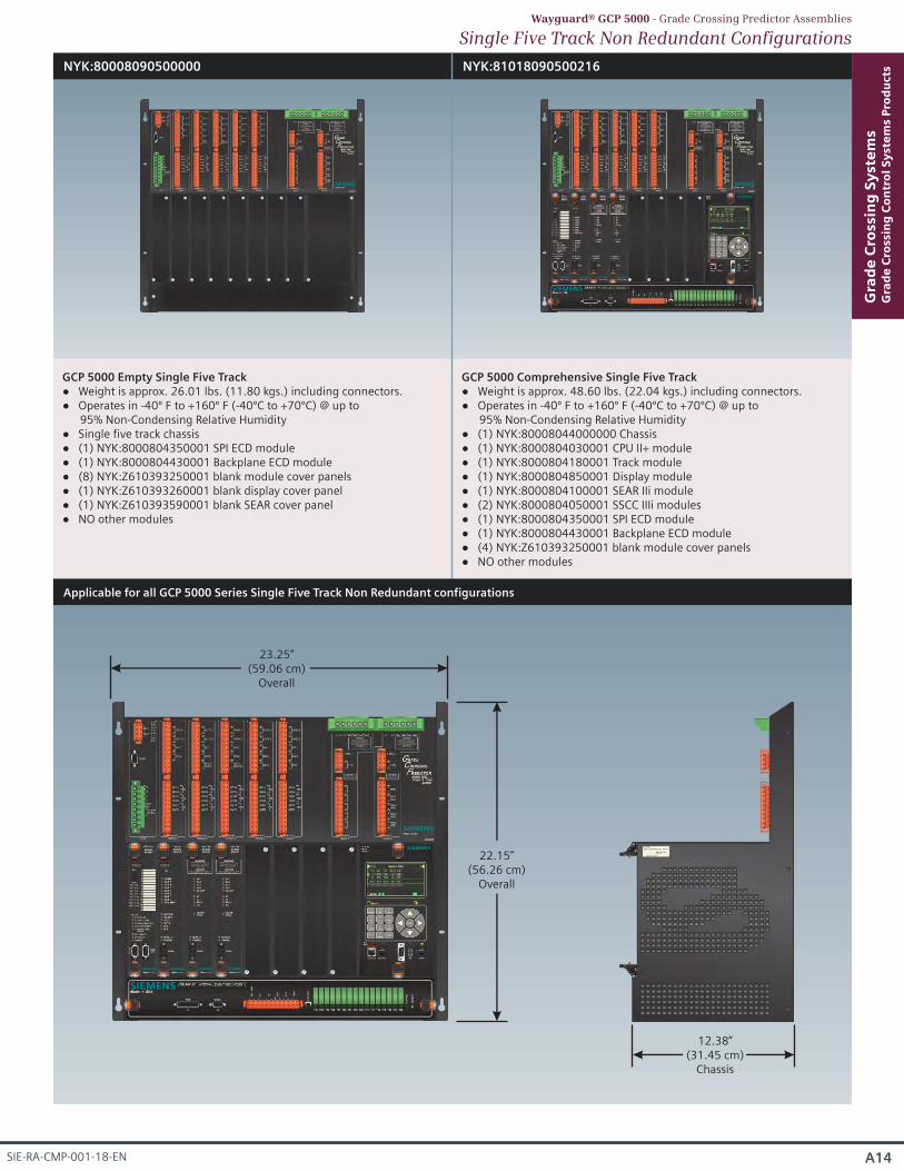
NYK:80008090500000
GCP 5000 Empty Single Five Track Weight is approx. 26.01 lbs. (11.80 kgs.) including connectors. Operates in -40º F to +160º F (-40ºC to +70ºC) @ up to
95% Non-Condensing Relative Humidity Single five track chassis (1) NYK:8000804350001 SPI ECD module (1) NYK:8000804430001 Backplane ECD module (8) NYK:Z610393250001 blank module cover panels (1) NYK:Z610393260001 blank display cover panel (1) NYK:Z610393590001 blank SEAR cover panel NO other modules
NYK:81018090500216
GCP 5000 Comprehensive Single Five Track Weight is approx. 48.60 lbs. (22.04 kgs.) including connectors. Operates in -40º F to +160º F (-40ºC to +70ºC) @ up to
95% Non-Condensing Relative Humidity (1) NYK:80008044000000 Chassis (1) NYK:8000804030001 CPU II+ module (1) NYK:8000804180001 Track module (1) NYK:8000804850001 Display module (1) NYK:8000804100001 SEAR IIi module (2) NYK:8000804050001 SSCC IIIi modules (1) NYK:8000804350001 SPI ECD module (1) NYK:8000804430001 Backplane ECD module (4) NYK:Z610393250001 blank module cover panels NO other modules
Single Five Track Non Redundant ConfigurationsWayguard® GCP 5000 - Grade Crossing Predictor Assemblies
Applicable for all GCP 5000 Series Single Five Track Non Redundant configurations
22.15”(56.26 cm)
Overall
23.25”(59.06 cm)
Overall
12.38”(31.45 cm)
Chassis
A14
Gra
de
Cro
ssin
g S
yst
em
sG
rad
e C
ross
ing
Co
ntr
ol
Sy
ste
ms
Pro
du
cts
SIE-RA-CMP-001-18-EN
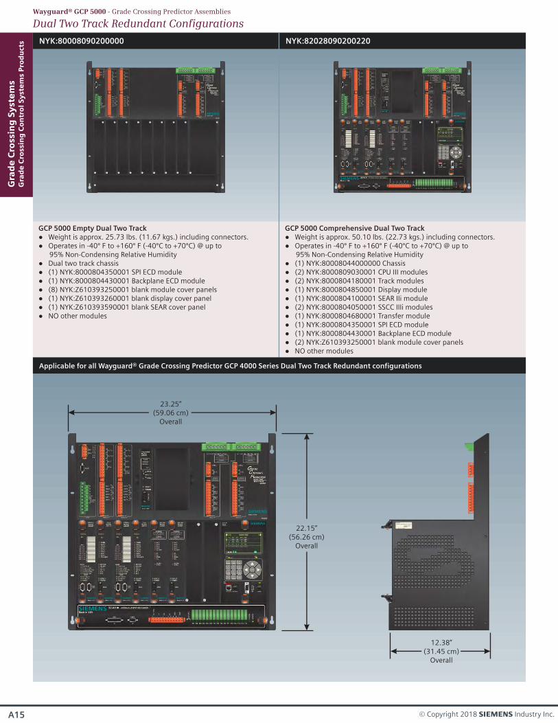
NYK:80008090200000
GCP 5000 Empty Dual Two Track Weight is approx. 25.73 lbs. (11.67 kgs.) including connectors. Operates in -40º F to +160º F (-40ºC to +70ºC) @ up to
95% Non-Condensing Relative Humidity Dual two track chassis (1) NYK:8000804350001 SPI ECD module (1) NYK:8000804430001 Backplane ECD module (8) NYK:Z610393250001 blank module cover panels (1) NYK:Z610393260001 blank display cover panel (1) NYK:Z610393590001 blank SEAR cover panel NO other modules
NYK:82028090200220
GCP 5000 Comprehensive Dual Two Track Weight is approx. 50.10 lbs. (22.73 kgs.) including connectors. Operates in -40º F to +160º F (-40ºC to +70ºC) @ up to
95% Non-Condensing Relative Humidity (1) NYK:80008044000000 Chassis (2) NYK:8000809030001 CPU III modules (2) NYK:8000804180001 Track modules (1) NYK:8000804850001 Display module (1) NYK:8000804100001 SEAR IIi module (2) NYK:8000804050001 SSCC IIIi modules (1) NYK:8000804680001 Transfer module (1) NYK:8000804350001 SPI ECD module (1) NYK:8000804430001 Backplane ECD module (2) NYK:Z610393250001 blank module cover panels NO other modules
Dual Two Track Redundant ConfigurationsWayguard® GCP 5000 - Grade Crossing Predictor Assemblies
Applicable for all Wayguard® Grade Crossing Predictor GCP 4000 Series Dual Two Track Redundant configurations
22.15”(56.26 cm)
Overall
23.25”(59.06 cm)
Overall
12.38”(31.45 cm)
Overall
Gra
de
Cro
ssin
g S
yst
em
sG
rad
e C
ross
ing
Co
ntr
ol
Sy
ste
ms
Pro
du
cts
A15 © Copyright 2018 s Industry Inc.

NYK:80008090700000
GCP 5000 Empty Dual Three Track Weight is approx. 26.01 lbs. (11.80 kgs.) including connectors. Operates in -40º F to +160º F (-40ºC to +70ºC) @ up to
95% Non-Condensing Relative Humidity Single five track chassis (1) NYK:8000804350001 SPI ECD module (1) NYK:8000804430001 Backplane ECD module (8) NYK:Z610393250001 blank module cover panels (1) NYK:Z610393260001 blank display cover panel (1) NYK:Z610393590001 blank SEAR cover panel NO other modules
NYK:82038090700220
GCP 5000 Comprehensive Dual Three Track Weight is approx. 48.60 lbs. (22.04 kgs.) including connectors. Operates in -40º F to +160º F (-40ºC to +70ºC) @ up to
95% Non-Condensing Relative Humidity (1) NYK:80008044000000 Chassis (2) NYK:8000804030001 CPU II+ modules (1) NYK:8000804180001 Track module (1) NYK:8000804850001 Display module (1) NYK:8000804100001 SEAR IIi module (2) NYK:8000804050001 SSCC IIIi modules (1) NYK:8000804350001 SPI ECD module (1) NYK:8000804430001 Backplane ECD module (4) NYK:Z610393250001 blank module cover panels NO other modules
Dual Three Track Redundant ConfigurationsWayguard® GCP 5000 - Grade Crossing Predictor Assemblies
Applicable for all GCP 5000 Series Single Five Track Non Redundant configurations
22.15”(56.26 cm)
Overall
23.25”(59.06 cm)
Overall
12.38”(31.45 cm)
Chassis
A16
Gra
de
Cro
ssin
g S
yst
em
sG
rad
e C
ross
ing
Co
ntr
ol
Sy
ste
ms
Pro
du
cts
SIE-RA-CMP-001-18-EN
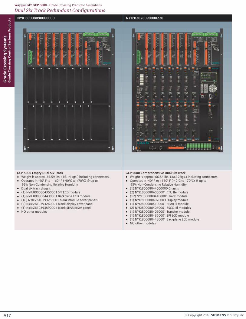
NYK:80008090000000 NYK:82028090000220
GCP 5000 Empty Dual Six Track Weight is approx. 35.59 lbs. (16.14 kgs.) including connectors. Operates in -40º F to +160º F (-40ºC to +70ºC) @ up to
95% Non-Condensing Relative Humidity Dual six track chassis (1) NYK:8000804350001 SPI ECD module (1) NYK:8000804430001 Backplane ECD module (16) NYK:Z610393250001 blank module cover panels (2) NYK:Z610393260001 blank display cover panel (1) NYK:Z610393590001 blank SEAR cover panel NO other modules
GCP 5000 Comprehensive Dual Six Track Weight is approx. 66.84 lbs. (30.32 kgs.) including connectors. Operates in -40º F to +160º F (-40ºC to +70ºC) @ up to
95% Non-Condensing Relative Humidity (1) NYK:80008044000000 Chassis (2) NYK:8000804030001 CPU II+ module (12) NYK:8000804180001 Track module (1) NYK:8000804070003 Display module (1) NYK:8000804100001 SEAR IIi module (2) NYK:8000804050001 SSCC IIIi modules (1) NYK:8000804060001 Transfer module (1) NYK:8000804350001 SPI ECD module (1) NYK:8000804430001 Backplane ECD module NO other modules
Gra
de
Cro
ssin
g S
yst
em
sG
rad
e C
ross
ing
Co
ntr
ol
Sy
ste
ms
Pro
du
cts
A17 © Copyright 2018 s Industry Inc.
Dual Six Track Redundant ConfigurationsWayguard® GCP 5000 - Grade Crossing Predictor Assemblies
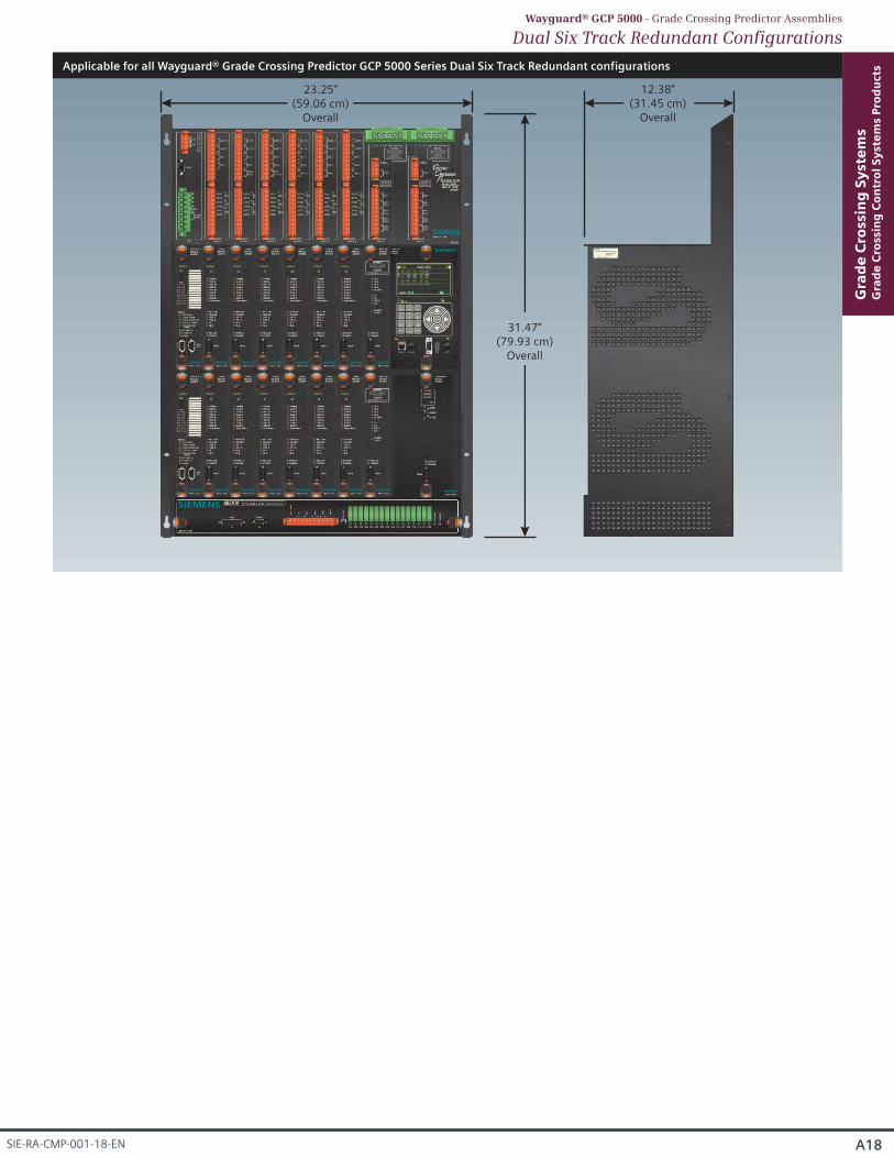
Applicable for all Wayguard® Grade Crossing Predictor GCP 5000 Series Dual Six Track Redundant configurations
31.47”(79.93 cm)
Overall
23.25”(59.06 cm)
Overall
12.38”(31.45 cm)
Overall
Dual Six Track Redundant ConfigurationsWayguard® GCP 5000 - Grade Crossing Predictor Assemblies
A18
Gra
de
Cro
ssin
g S
yst
em
sG
rad
e C
ross
ing
Co
ntr
ol
Sy
ste
ms
Pro
du
cts
SIE-RA-CMP-001-18-EN
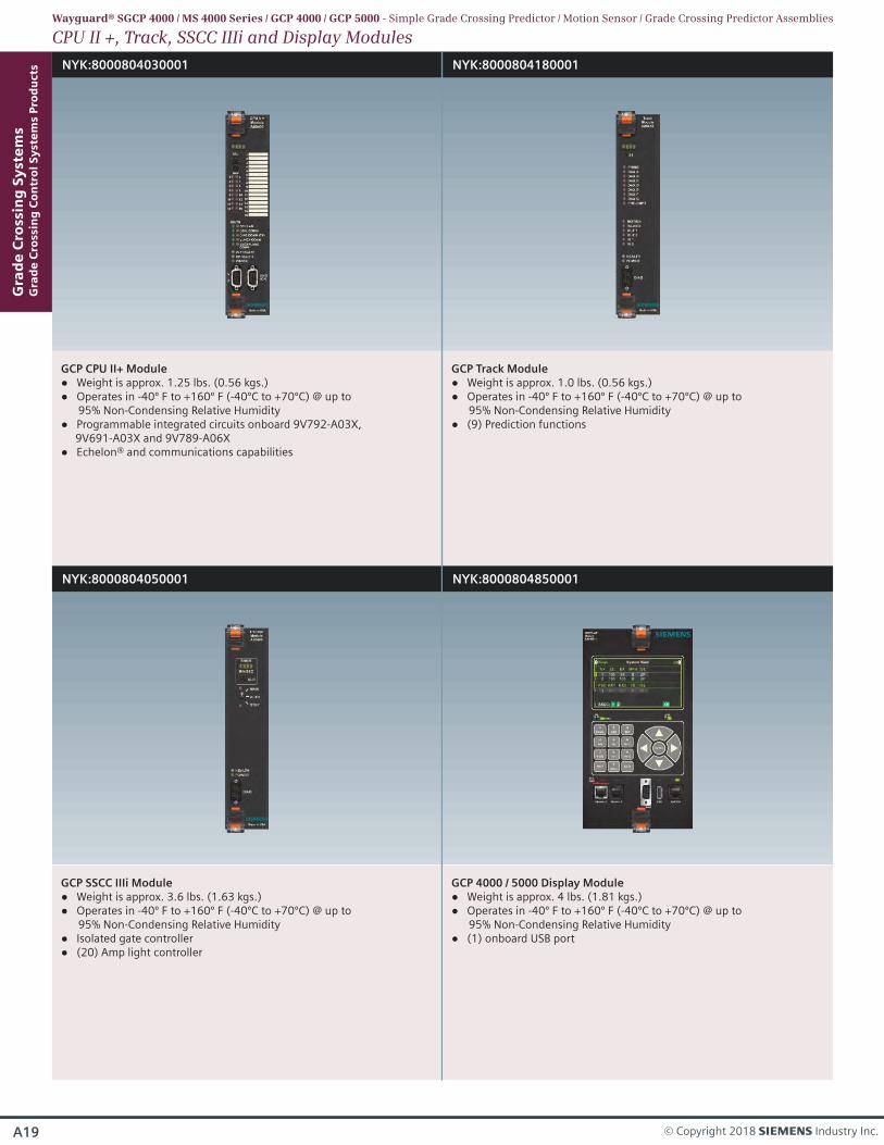
NYK:8000804180001
GCP Track Module Weight is approx. 1.0 lbs. (0.56 kgs.) Operates in -40º F to +160º F (-40ºC to +70ºC) @ up to
95% Non-Condensing Relative Humidity (9) Prediction functions
Gra
de
Cro
ssin
g S
yst
em
sG
rad
e C
ross
ing
Co
ntr
ol
Sy
ste
ms
Pro
du
cts
A19 © Copyright 2018 s Industry Inc.
CPU II +, Track, SSCC IIIi and Display ModulesWayguard® SGCP 4000 / MS 4000 Series / GCP 4000 / GCP 5000 - Simple Grade Crossing Predictor / Motion Sensor / Grade Crossing Predictor Assemblies
NYK:8000804030001
GCP CPU II+ Module Weight is approx. 1.25 lbs. (0.56 kgs.) Operates in -40º F to +160º F (-40ºC to +70ºC) @ up to
95% Non-Condensing Relative Humidity Programmable integrated circuits onboard 9V792-A03X,
9V691-A03X and 9V789-A06X Echelon® and communications capabilities
NYK:8000804050001
GCP SSCC IIIi Module Weight is approx. 3.6 lbs. (1.63 kgs.) Operates in -40º F to +160º F (-40ºC to +70ºC) @ up to
95% Non-Condensing Relative Humidity Isolated gate controller (20) Amp light controller
NYK:8000804850001
GCP 4000 / 5000 Display Module Weight is approx. 4 lbs. (1.81 kgs.) Operates in -40º F to +160º F (-40ºC to +70ºC) @ up to
95% Non-Condensing Relative Humidity (1) onboard USB port
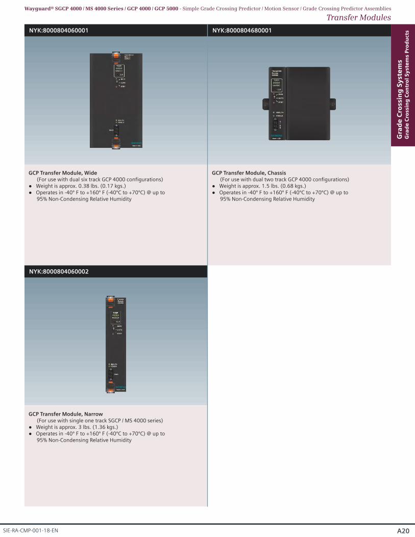
NYK:8000804060001
GCP Transfer Module, Wide (For use with dual six track GCP 4000 configurations)
Weight is approx. 0.38 lbs. (0.17 kgs.) Operates in -40º F to +160º F (-40ºC to +70ºC) @ up to
95% Non-Condensing Relative Humidity
NYK:8000804060002
GCP Transfer Module, Narrow (For use with single one track SGCP / MS 4000 series)
Weight is approx. 3 lbs. (1.36 kgs.) Operates in -40º F to +160º F (-40ºC to +70ºC) @ up to
95% Non-Condensing Relative Humidity
NYK:8000804680001
GCP Transfer Module, Chassis (For use with dual two track GCP 4000 configurations)
Weight is approx. 1.5 lbs. (0.68 kgs.) Operates in -40º F to +160º F (-40ºC to +70ºC) @ up to
95% Non-Condensing Relative Humidity
A20
Gra
de
Cro
ssin
g S
yst
em
sG
rad
e C
ross
ing
Co
ntr
ol
Sy
ste
ms
Pro
du
cts
SIE-RA-CMP-001-18-EN
Transfer ModulesWayguard® SGCP 4000 / MS 4000 Series / GCP 4000 / GCP 5000 - Simple Grade Crossing Predictor / Motion Sensor / Grade Crossing Predictor Assemblies
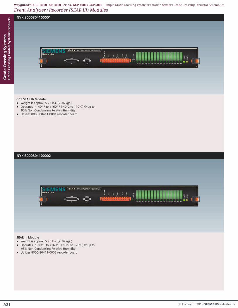
NYK:8000804100001
GCP SEAR IIi Module Weight is approx. 5.25 lbs. (2.36 kgs.) Operates in -40º F to +160º F (-40ºC to +70ºC) @ up to
95% Non-Condensing Relative Humidity Utilizes 8000-80411-0001 recorder board
NYK:8000804100002
SEAR IIi Module Weight is approx. 5.25 lbs. (2.36 kgs.) Operates in -40º F to +160º F (-40ºC to +70ºC) @ up to
95% Non-Condensing Relative Humidity Utilizes 8000-80411-0002 recorder board
Gra
de
Cro
ssin
g S
yst
em
sG
rad
e C
ross
ing
Co
ntr
ol
Sy
ste
ms
Pro
du
cts
A21 © Copyright 2018 s Industry Inc.
Event Analyzer / Recorder (SEAR IIi) ModulesWayguard® SGCP 4000 / MS 4000 Series / GCP 4000 / GCP 5000 - Simple Grade Crossing Predictor / Motion Sensor / Grade Crossing Predictor Assemblies
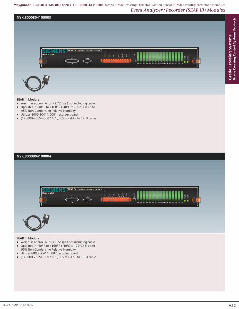
NYK:8000804100003
NYK:8000804100004
SEAR IIi Module Weight is approx. 6 lbs. (2.72 kgs.) not including cable Operates in -40º F to +160º F (-40ºC to +70ºC) @ up to
95% Non-Condensing Relative Humidity Utilizes 8000-80411-0001 recorder board (1) 8000-26654-0002 10’ (3.05 m) SEAR to CRTU cable
SEAR IIi Module Weight is approx. 6 lbs. (2.72 kgs.) not including cable Operates in -40º F to +160º F (-40ºC to +70ºC) @ up to
95% Non-Condensing Relative Humidity Utilizes 8000-80411-0002 recorder board (1) 8000-26654-0002 10’ (3.05 m) SEAR to CRTU cable
A22
Gra
de
Cro
ssin
g S
yst
em
sG
rad
e C
ross
ing
Co
ntr
ol
Sy
ste
ms
Pro
du
cts
SIE-RA-CMP-001-18-EN
Event Analyzer / Recorder (SEAR IIi) ModulesWayguard® SGCP 4000 / MS 4000 Series / GCP 4000 / GCP 5000 - Simple Grade Crossing Predictor / Motion Sensor / Grade Crossing Predictor Assemblies
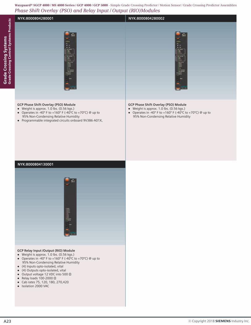
NYK:8000804280001
GCP Phase Shift Overlay (PSO) Module Weight is approx. 1.0 lbs. (0.56 kgs.) Operates in -40º F to +160º F (-40ºC to +70ºC) @ up to
95% Non-Condensing Relative Humidity Programmable integrated circuits onboard 9V386-A01X,
NYK:8000804280002
GCP Phase Shift Overlay (PSO) Module Weight is approx. 1.0 lbs. (0.56 kgs.) Operates in -40º F to +160º F (-40ºC to +70ºC) @ up to
95% Non-Condensing Relative Humidity
Gra
de
Cro
ssin
g S
yst
em
sG
rad
e C
ross
ing
Co
ntr
ol
Sy
ste
ms
Pro
du
cts
A23 © Copyright 2018 s Industry Inc.
Phase Shift Overlay (PSO) and Relay Input / Output (RIO)ModulesWayguard® SGCP 4000 / MS 4000 Series / GCP 4000 / GCP 5000 - Simple Grade Crossing Predictor / Motion Sensor / Grade Crossing Predictor Assemblies
NYK:8000804130001
GCP Relay Input /Output (RIO) Module Weight is approx. 1.0 lbs. (0.56 kgs.) Operates in -40º F to +160º F (-40ºC to +70ºC) @ up to
95% Non-Condensing Relative Humidity (4) Inputs opto-isolated, vital (4) Outputs opto-isolated, vital Output voltage 12 VDC into 500 Ω Relay loads 100-2000 Ω Cab rates 75, 120, 180, 270,420 Isolation 2000 VAC
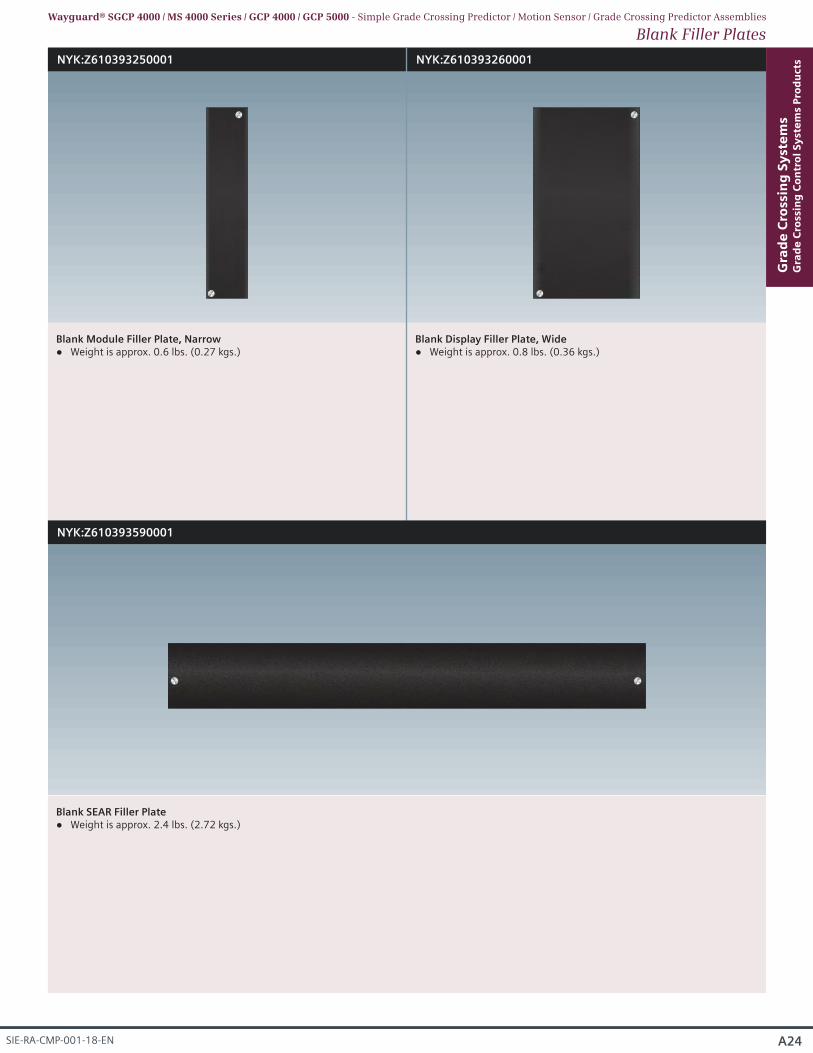
NYK:Z610393250001 NYK:Z610393260001
Blank Module Filler Plate, Narrow Weight is approx. 0.6 lbs. (0.27 kgs.)
Blank Display Filler Plate, Wide Weight is approx. 0.8 lbs. (0.36 kgs.)
Blank SEAR Filler Plate Weight is approx. 2.4 lbs. (2.72 kgs.)
A24
Gra
de
Cro
ssin
g S
yst
em
sG
rad
e C
ross
ing
Co
ntr
ol
Sy
ste
ms
Pro
du
cts
SIE-RA-CMP-001-18-EN
Blank Filler PlatesWayguard® SGCP 4000 / MS 4000 Series / GCP 4000 / GCP 5000 - Simple Grade Crossing Predictor / Motion Sensor / Grade Crossing Predictor Assemblies
NYK:Z610393590001
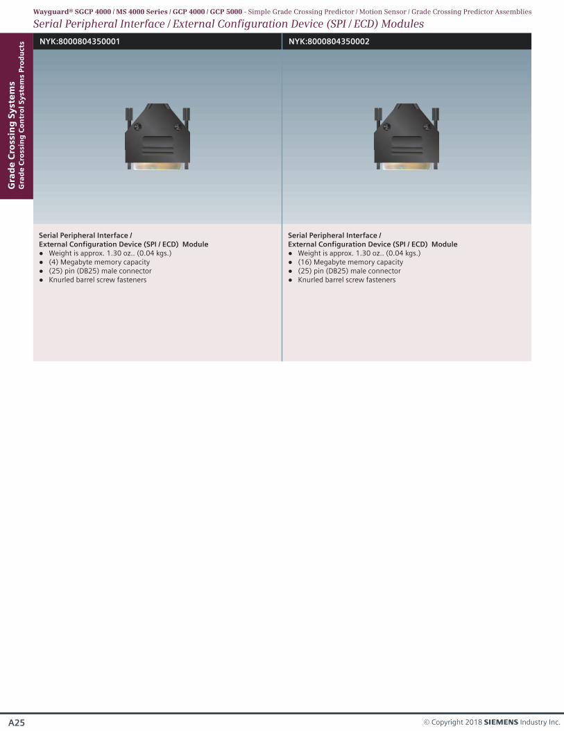
Serial Peripheral Interface / External Configuration Device (SPI / ECD) Module
Weight is approx. 1.30 oz.. (0.04 kgs.) (4) Megabyte memory capacity
(25) pin (DB25) male connector Knurled barrel screw fasteners
Serial Peripheral Interface / External Configuration Device (SPI / ECD) Module
Weight is approx. 1.30 oz.. (0.04 kgs.) (16) Megabyte memory capacity (25) pin (DB25) male connector Knurled barrel screw fasteners
Gra
de
Cro
ssin
g S
yst
em
sG
rad
e C
ross
ing
Co
ntr
ol
Sy
ste
ms
Pro
du
cts
A25 © Copyright 2018 s Industry Inc.
Serial Peripheral Interface / External Configuration Device (SPI / ECD) Modules
NYK:8000804350001 NYK:8000804350002
Wayguard® SGCP 4000 / MS 4000 Series / GCP 4000 / GCP 5000 - Simple Grade Crossing Predictor / Motion Sensor / Grade Crossing Predictor Assemblies

A26
Gra
de
Cro
ssin
g S
yst
em
sG
rad
e C
ross
ing
Co
ntr
ol
Sy
ste
ms
Pro
du
cts
SIE-RA-CMP-001-18-EN
A27 © Copyright 2018 s Industry Inc.
Gra
de
Cro
ssin
g S
yst
em
sG
rad
e C
ross
ing
Co
ntr
ol
Sy
ste
ms
Pro
du
cts
EGMSSeries
Wayguard®
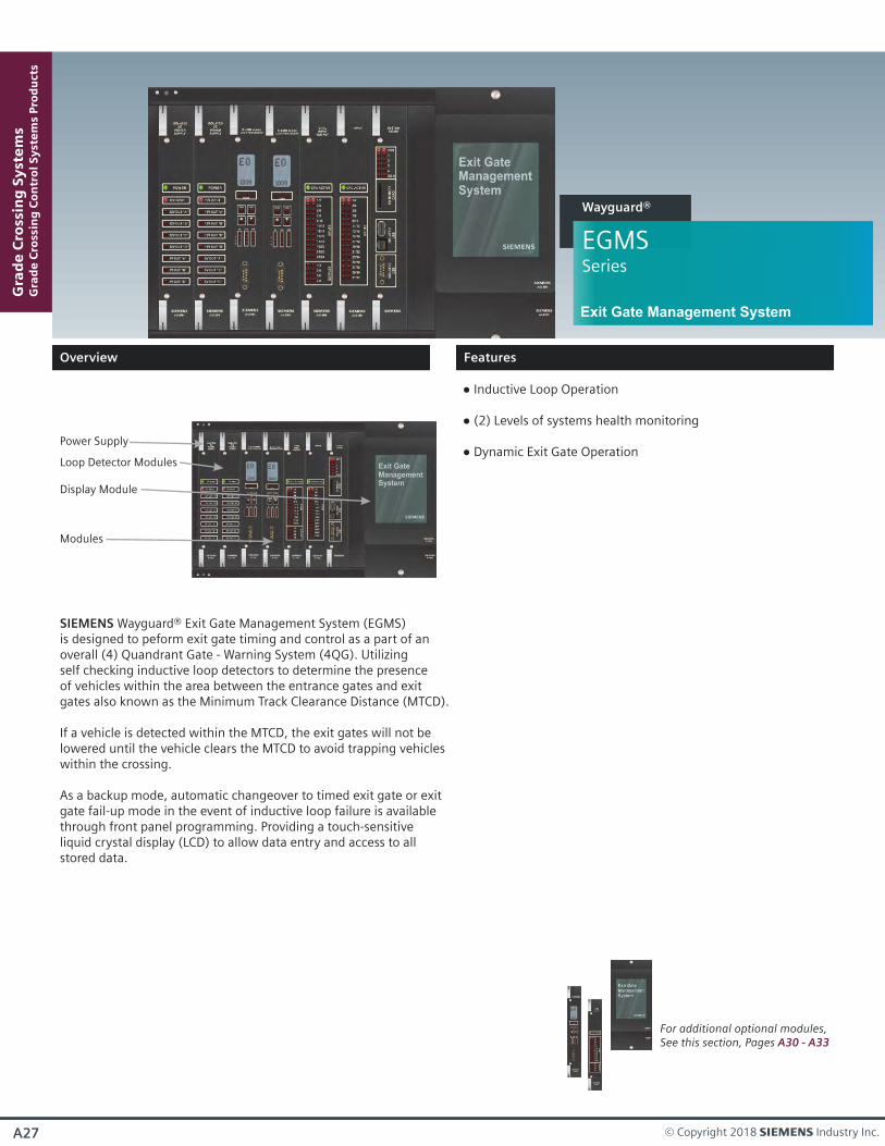
Loop Detector Modules
Power Supply
Modules
For additional optional modules, See this section, Pages A30 - A33
SIEMENS Wayguard® Exit Gate Management System (EGMS)is designed to peform exit gate timing and control as a part of an overall (4) Quandrant Gate - Warning System (4QG). Utilizingself checking inductive loop detectors to determine the presence of vehicles within the area between the entrance gates and exit gates also known as the Minimum Track Clearance Distance (MTCD).
If a vehicle is detected within the MTCD, the exit gates will not be lowered until the vehicle clears the MTCD to avoid trapping vehicles within the crossing.
As a backup mode, automatic changeover to timed exit gate or exit gate fail-up mode in the event of inductive loop failure is available through front panel programming. Providing a touch-sensitive liquid crystal display (LCD) to allow data entry and access to all stored data.
Display Module
Inductive Loop Operation
(2) Levels of systems health monitoring
Dynamic Exit Gate Operation
Exit Gate Management System
Overview
Features
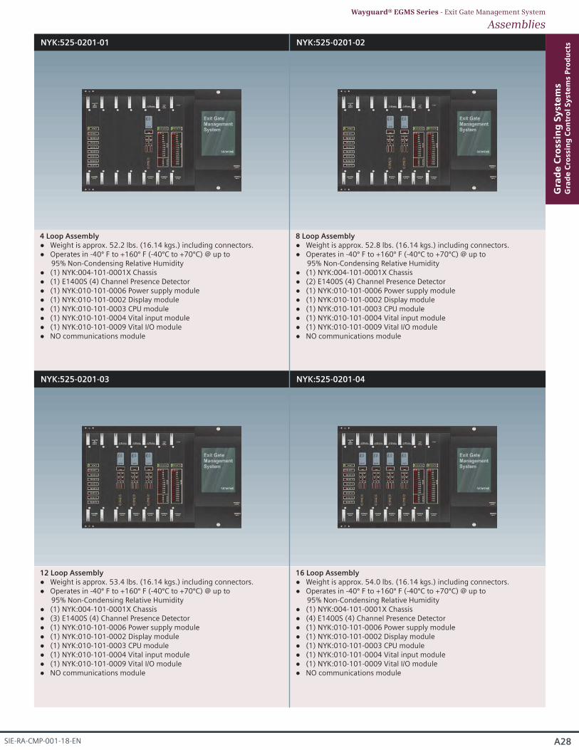
NYK:525-0201-01 NYK:525-0201-02
4 Loop Assembly Weight is approx. 52.2 lbs. (16.14 kgs.) including connectors. Operates in -40º F to +160º F (-40ºC to +70ºC) @ up to
95% Non-Condensing Relative Humidity (1) NYK:004-101-0001X Chassis (1) E1400S (4) Channel Presence Detector (1) NYK:010-101-0006 Power supply module (1) NYK:010-101-0002 Display module (1) NYK:010-101-0003 CPU module (1) NYK:010-101-0004 Vital input module (1) NYK:010-101-0009 Vital I/O module NO communications module
8 Loop Assembly Weight is approx. 52.8 lbs. (16.14 kgs.) including connectors. Operates in -40º F to +160º F (-40ºC to +70ºC) @ up to
95% Non-Condensing Relative Humidity (1) NYK:004-101-0001X Chassis (2) E1400S (4) Channel Presence Detector (1) NYK:010-101-0006 Power supply module (1) NYK:010-101-0002 Display module (1) NYK:010-101-0003 CPU module (1) NYK:010-101-0004 Vital input module (1) NYK:010-101-0009 Vital I/O module NO communications module
NYK:525-0201-03 NYK:525-0201-04
12 Loop Assembly Weight is approx. 53.4 lbs. (16.14 kgs.) including connectors. Operates in -40º F to +160º F (-40ºC to +70ºC) @ up to
95% Non-Condensing Relative Humidity (1) NYK:004-101-0001X Chassis (3) E1400S (4) Channel Presence Detector (1) NYK:010-101-0006 Power supply module (1) NYK:010-101-0002 Display module (1) NYK:010-101-0003 CPU module (1) NYK:010-101-0004 Vital input module (1) NYK:010-101-0009 Vital I/O module NO communications module
16 Loop Assembly Weight is approx. 54.0 lbs. (16.14 kgs.) including connectors. Operates in -40º F to +160º F (-40ºC to +70ºC) @ up to
95% Non-Condensing Relative Humidity (1) NYK:004-101-0001X Chassis (4) E1400S (4) Channel Presence Detector (1) NYK:010-101-0006 Power supply module (1) NYK:010-101-0002 Display module (1) NYK:010-101-0003 CPU module (1) NYK:010-101-0004 Vital input module (1) NYK:010-101-0009 Vital I/O module NO communications module
A28
Gra
de
Cro
ssin
g S
yst
em
sG
rad
e C
ross
ing
Co
ntr
ol
Sy
ste
ms
Pro
du
cts
SIE-RA-CMP-001-18-EN
AssembliesWayguard® EGMS Series - Exit Gate Management System
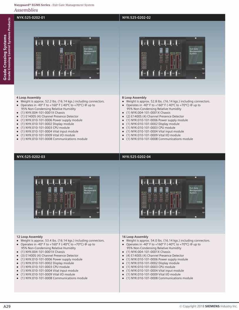
NYK:525-0202-01 NYK:525-0202-02
NYK:525-0202-03 NYK:525-0202-04
4 Loop Assembly Weight is approx. 52.2 lbs. (16.14 kgs.) including connectors. Operates in -40º F to +160º F (-40ºC to +70ºC) @ up to
95% Non-Condensing Relative Humidity (1) NYK:004-101-0001X Chassis (1) E1400S (4) Channel Presence Detector (1) NYK:010-101-0006 Power supply module (1) NYK:010-101-0002 Display module (1) NYK:010-101-0003 CPU module (1) NYK:010-101-0004 Vital input module (1) NYK:010-101-0009 Vital I/O module (1) NYK:010-101-0008 Communications module
8 Loop Assembly Weight is approx. 52.8 lbs. (16.14 kgs.) including connectors. Operates in -40º F to +160º F (-40ºC to +70ºC) @ up to
95% Non-Condensing Relative Humidity (1) NYK:004-101-0001X Chassis (2) E1400S (4) Channel Presence Detector (1) NYK:010-101-0006 Power supply module (1) NYK:010-101-0002 Display module (1) NYK:010-101-0003 CPU module (1) NYK:010-101-0004 Vital input module (1) NYK:010-101-0009 Vital I/O module (1) NYK:010-101-0008 Communications module
12 Loop Assembly Weight is approx. 53.4 lbs. (16.14 kgs.) including connectors. Operates in -40º F to +160º F (-40ºC to +70ºC) @ up to
95% Non-Condensing Relative Humidity (1) NYK:004-101-0001X Chassis (3) E1400S (4) Channel Presence Detector (1) NYK:010-101-0006 Power supply module (1) NYK:010-101-0002 Display module (1) NYK:010-101-0003 CPU module (1) NYK:010-101-0004 Vital input module (1) NYK:010-101-0009 Vital I/O module (1) NYK:010-101-0008 Communications module
16 Loop Assembly Weight is approx. 54.0 lbs. (16.14 kgs.) including connectors. Operates in -40º F to +160º F (-40ºC to +70ºC) @ up to
95% Non-Condensing Relative Humidity (1) NYK:004-101-0001X Chassis (4) E1400S (4) Channel Presence Detector (1) NYK:010-101-0006 Power supply module (1) NYK:010-101-0002 Display module (1) NYK:010-101-0003 CPU module (1) NYK:010-101-0004 Vital input module (1) NYK:010-101-0009 Vital I/O module (1) NYK:010-101-0008 Communications module
Gra
de
Cro
ssin
g S
yst
em
sG
rad
e C
ross
ing
Co
ntr
ol
Sy
ste
ms
Pro
du
cts
AssembliesWayguard® EGMS Series - Exit Gate Management System
A29 © Copyright 2018 s Industry Inc.
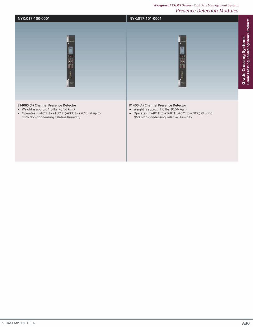
NYK:017-100-0001
E1400S (4) Channel Presence Detector Weight is approx. 1.0 lbs. (0.56 kgs.) Operates in -40º F to +160º F (-40ºC to +70ºC) @ up to
95% Non-Condensing Relative Humidity
NYK:017-101-0001
P1400 (4) Channel Presence Detector Weight is approx. 1.0 lbs. (0.56 kgs.) Operates in -40º F to +160º F (-40ºC to +70ºC) @ up to
95% Non-Condensing Relative Humidity
A30
Gra
de
Cro
ssin
g S
yst
em
sG
rad
e C
ross
ing
Co
ntr
ol
Sy
ste
ms
Pro
du
cts
SIE-RA-CMP-001-18-EN
Presence Detection ModulesWayguard® EGMS Series - Exit Gate Management System
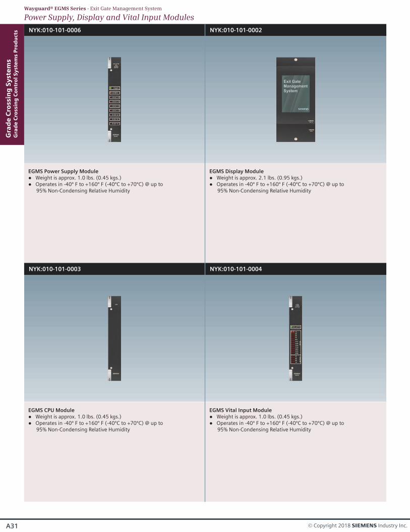
NYK:010-101-0006
EGMS Power Supply Module Weight is approx. 1.0 lbs. (0.45 kgs.) Operates in -40º F to +160º F (-40ºC to +70ºC) @ up to
95% Non-Condensing Relative Humidity
NYK:010-101-0002
EGMS Display Module Weight is approx. 2.1 lbs. (0.95 kgs.) Operates in -40º F to +160º F (-40ºC to +70ºC) @ up to
95% Non-Condensing Relative Humidity
NYK:010-101-0003
EGMS CPU Module Weight is approx. 1.0 lbs. (0.45 kgs.) Operates in -40º F to +160º F (-40ºC to +70ºC) @ up to
95% Non-Condensing Relative Humidity
NYK:010-101-0004
EGMS Vital Input Module Weight is approx. 1.0 lbs. (0.45 kgs.) Operates in -40º F to +160º F (-40ºC to +70ºC) @ up to
95% Non-Condensing Relative Humidity
Gra
de
Cro
ssin
g S
yst
em
sG
rad
e C
ross
ing
Co
ntr
ol
Sy
ste
ms
Pro
du
cts
A31 © Copyright 2018 s Industry Inc.
Power Supply, Display and Vital Input ModulesWayguard® EGMS Series - Exit Gate Management System
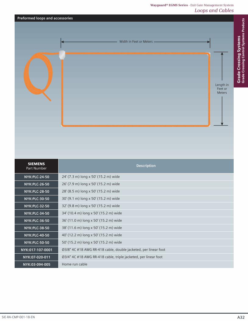
Preformed loops and accessories
Length inFeet orMeters
Width in Feet or Meters
A32
Gra
de
Cro
ssin
g S
yst
em
sG
rad
e C
ross
ing
Co
ntr
ol
Sy
ste
ms
Pro
du
cts
SIE-RA-CMP-001-18-EN
Loops and CablesWayguard® EGMS Series - Exit Gate Management System
NYK:PLC-24-50
s Part Number
24’ (7.3 m) long x 50’ (15.2 m) wide
Description
NYK:PLC-26-50 26’ (7.9 m) long x 50’ (15.2 m) wide
NYK:PLC-28-50 28’ (8.5 m) long x 50’ (15.2 m) wide
NYK:PLC-30-50 30’ (9.1 m) long x 50’ (15.2 m) wide
NYK:PLC-32-50 32’ (9.8 m) long x 50’ (15.2 m) wide
NYK:PLC-34-50 34’ (10.4 m) long x 50’ (15.2 m) wide
NYK:PLC-36-50 36’ (11.0 m) long x 50’ (15.2 m) wide
NYK:PLC-38-50 38’ (11.6 m) long x 50’ (15.2 m) wide
NYK:PLC-40-50 40’ (12.2 m) long x 50’ (15.2 m) wide
NYK:PLC-50-50 50’ (15.2 m) long x 50’ (15.2 m) wide
NYK:017-107-0001 Ø3/8” 4C #18 AWG RR-418 cable, double jacketed, per linear foot
NYK:07-020-011 Ø3/4” 4C #18 AWG RR-418 cable, triple jacketed, per linear foot
NYK:03-094-005 Home run cable
Gra
de
Cro
ssin
g S
yst
em
sG
rad
e C
ross
ing
Co
ntr
ol
Sy
ste
ms
Pro
du
cts
A33 © Copyright 2018 s Industry Inc.
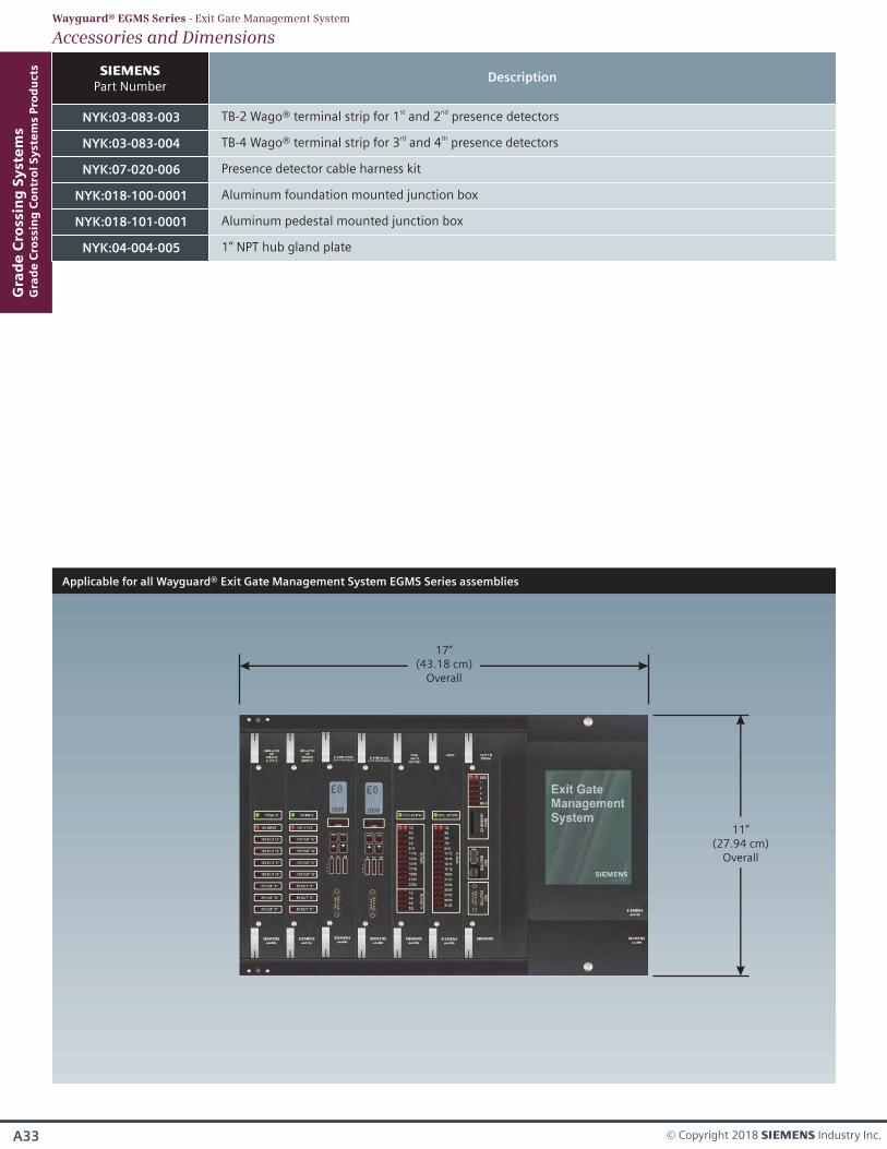
Applicable for all Wayguard® Exit Gate Management System EGMS Series assemblies
17”(43.18 cm)
Overall
11”(27.94 cm)
Overall
NYK:03-083-003
s Part Number
st ndTB-2 Wago® terminal strip for 1 and 2 presence detectors
Description
NYK:03-083-004 TB-4 Wago® terminal strip for 3 and 4 presence detectorsrd th
NYK:07-020-006 Presence detector cable harness kit
NYK:018-100-0001 Aluminum foundation mounted junction box
NYK:018-101-0001 Aluminum pedestal mounted junction box
NYK:04-004-005 1” NPT hub gland plate
Accessories and DimensionsWayguard® EGMS Series - Exit Gate Management System
A34
Gra
de
Cro
ssin
g S
yst
em
sG
rad
e C
ross
ing
Co
ntr
ol
Sy
ste
ms
Pro
du
cts
SIE-RA-CMP-001-18-EN
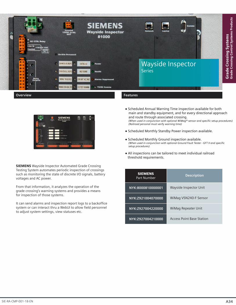
Wayside InspectorSeries
NYK:8000810000001
s Part Number
Wayside Inspector Unit
Description
NYK:Z921004070000 WiMag VSN240-F Sensor
NYK:Z927004220000 WiMag Repeater Unit
NYK:Z927004210000 Access Point Base Station
SIEMENS Wayside Inspector Automated Grade Crossing Testing System automates periodic inspection of crossings such as monitoring the state of discrete I/O signals, battery voltages and AC power.
From that information, it analyzes the operation of thegrade crossing’s warning systems and provides a meansfor inspection of those systems.
It can send alarms and inspection report logs to a backofficesystem or can interact thru a WebUI to allow field personnel to adjust system settings, view statuses etc.
Scheduled Annual Warning Time inspection available for both main and standby equipment, and for every directional approach and route through associated crossing. (When used in conjunction with optional WiMag® sensor and specific setup procedures) (Railroad personal must verify warning time)
Scheduled Monthly Standby Power inspection available.
Scheduled Monthly Ground inspection available. (When used in conjunction with optional Ground Fault Tester - GFT II and specific setup procedures)
All inspections can be tailored to meet individual railroad threshold requirements.
Overview
Features
A35 © Copyright 2018 s Industry Inc.
Gra
de
Cro
ssin
g S
yst
em
sG
rad
e C
ross
ing
Co
ntr
ol
Sy
ste
ms
Pro
du
cts
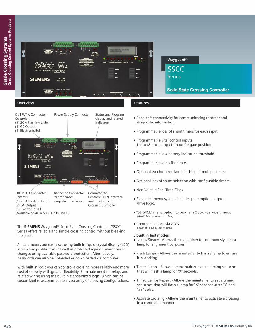
SSCCSeries
Wayguard®
The SIEMENS Wayguard® Solid State Crossing Controller (SSCC) Series offers reliable and simple crossing control without breaking the bank.
All parameters are easily set using built in liquid crystal display (LCD)screen and pushbuttons as well as protected against unauthorized changes using available password protection. Alternatively, passwords can also be uploaded or downloaded via computer.
With built in logic you can control a crossing more reliably and more cost effectively with greater flexibility. Eliminate need for relays and related wiring using the built in standardized logic, which can be customized to accommodate a vast array of crossing configurations.
Solid State Crossing Controller
Status and Programdisplay and relatedindicators
Connector toEchelon® LAN Interfaceand Inputs from Crossing Controller
Diagnostic ConnectorPort for directcomputer interfacing
Power Supply ConnectorOUTPUT A ConnectorControls:(1) 20 A Flashing Light(1) GC Output(1) Electronic Bell
OUTPUT B ConnectorControls:(1) 20 A Flashing Light(2) GC Output(1) Electronic Bell(Available on 40 A SSCC Units ONLY!)
Echelon® connectivity for communicating recorder and diagnostic information.
Programmable loss of shunt timers for each input.
Programmable vital control inputs. Up to (8) including (1) input for gate position.
Programmable low battery indication threshold.
Programmable lamp flash rate.
Optional synchronized lamp flashing of multiple units.
Optional loss of shunt selection with configurable timers.
Non Volatile Real-Time Clock.
Expanded menu system includes pre-emption output drive logic.
“SERVICE” menu option to program Out-of-Service timers. (Available on select models)
Communications via ATCS. (Available on select models)
5 built in test modes Lamps Steady - Allows the maintainer to continuously light a
lamp for alignment purposes.
Flash Lamps - Allows the maintainer to flash a lamp to ensure it is working.
Timed Lamps- Allows the maintainer to set a timing sequence that will flash a lamp for "X" seconds.
Timed Lamps Repeat - Allows the maintainer to set a timing sequence that will flash a lamp for "X" seconds after "Y" and "2Y" delay.
Activate Crossing - Allows the maintainer to activate a crossing in a controlled manner.
Overview
Features
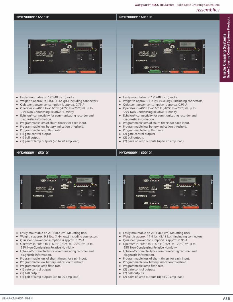
NYK:9000911651101 NYK:9000911601101
NYK:9000911650101 NYK:9000911600101
Easily mountable on 19” (48.3 cm) racks. Weight is approx. 9.6 lbs. (4.32 kgs.) including connectors. Quiescent power consumption is approx. 0.75 A Operates in -40º F to +160º F (-40ºC to +70ºC) @ up to
95% Non-Condensing Relative Humidity Echelon® connectivity for communicating recorder and
diagnostic information. Programmable loss of shunt timers for each input. Programmable low battery indication threshold. Programmable lamp flash rate. (1) gate control output (1) bell output (1) pair of lamp outputs (up to 20 amp load)
Easily mountable on 19” (48.3 cm) racks. Weight is approx. 11.2 lbs. (5.08 kgs.) including connectors. Quiescent power consumption is approx. 0.95 A Operates in -40º F to +160º F (-40ºC to +70ºC) @ up to
95% Non-Condensing Relative Humidity Echelon® connectivity for communicating recorder and
diagnostic information. Programmable loss of shunt timers for each input. Programmable low battery indication threshold. Programmable lamp flash rate. (2) gate control outputs (2) bell outputs (2) pairs of lamp outputs (up to 20 amp load)
Easily mountable on 23” (58.4 cm) Mounting Rack Weight is approx. 9.8 lbs. (4.44 kgs.) including connectors. Quiescent power consumption is approx. 0.75 A Operates in -40º F to +160º F (-40ºC to +70ºC) @ up to
95% Non-Condensing Relative Humidity Echelon® connectivity for communicating recorder and
diagnostic information. Programmable loss of shunt timers for each input. Programmable low battery indication threshold. Programmable lamp flash rate. (1) gate control output (1) bell output (1) pair of lamp outputs (up to 20 amp load)
Easily mountable on 23” (58.4 cm) Mounting Rack Weight is approx. 11.4 lbs. (5.13 kgs.) including connectors. Quiescent power consumption is approx. 0.95 A Operates in -40º F to +160º F (-40ºC to +70ºC) @ up to
95% Non-Condensing Relative Humidity Echelon® connectivity for communicating recorder and
diagnostic information. Programmable loss of shunt timers for each input. Programmable low battery indication threshold. Programmable lamp flash rate. (2) gate control outputs (2) bell outputs (2) pairs of lamp outputs (up to 20 amp load)
A36
Gra
de
Cro
ssin
g S
yst
em
sG
rad
e C
ross
ing
Co
ntr
ol
Sy
ste
ms
Pro
du
cts
SIE-RA-CMP-001-18-EN
AssembliesWayguard® SSCC IIIA Series - Solid State Crossing Controllers
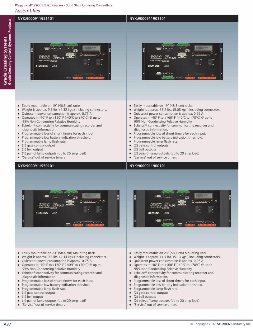
NYK:9000911951101 NYK:9000911901101
NYK:9000911950101 NYK:9000911900101
Easily mountable on 19” (48.3 cm) racks. Weight is approx. 9.6 lbs. (4.32 kgs.) including connectors. Quiescent power consumption is approx. 0.75 A Operates in -40º F to +160º F (-40ºC to +70ºC) @ up to
95% Non-Condensing Relative Humidity Echelon® connectivity for communicating recorder and
diagnostic information. Programmable loss of shunt timers for each input. Programmable low battery indication threshold. Programmable lamp flash rate. (1) gate control output (1) bell output (1) pair of lamp outputs (up to 20 amp load) “Service” out of service timers
Easily mountable on 19” (48.3 cm) racks. Weight is approx. 11.2 lbs. (5.08 kgs.) including connectors. Quiescent power consumption is approx. 0.95 A Operates in -40º F to +160º F (-40ºC to +70ºC) @ up to
95% Non-Condensing Relative Humidity Echelon® connectivity for communicating recorder and
diagnostic information. Programmable loss of shunt timers for each input. Programmable low battery indication threshold. Programmable lamp flash rate. (2) gate control outputs (2) bell outputs (2) pairs of lamp outputs (up to 20 amp load) “Service” out of service timers
Easily mountable on 23” (58.4 cm) Mounting Rack Weight is approx. 9.8 lbs. (4.44 kgs.) including connectors. Quiescent power consumption is approx. 0.75 A Operates in -40º F to +160º F (-40ºC to +70ºC) @ up to
95% Non-Condensing Relative Humidity Echelon® connectivity for communicating recorder and
diagnostic information. Programmable loss of shunt timers for each input. Programmable low battery indication threshold. Programmable lamp flash rate. (1) gate control output (1) bell output (1) pair of lamp outputs (up to 20 amp load) “Service” out of service timers
Easily mountable on 23” (58.4 cm) Mounting Rack Weight is approx. 11.4 lbs. (5.13 kgs.) including connectors. Quiescent power consumption is approx. 0.95 A Operates in -40º F to +160º F (-40ºC to +70ºC) @ up to
95% Non-Condensing Relative Humidity Echelon® connectivity for communicating recorder and
diagnostic information. Programmable loss of shunt timers for each input. Programmable low battery indication threshold. Programmable lamp flash rate. (2) gate control outputs (2) bell outputs (2) pairs of lamp outputs (up to 20 amp load) “Service” out of service timers
AssembliesWayguard® SSCC III PLUS Series - Solid State Crossing Controllers
A37 © Copyright 2018 s Industry Inc.
Gra
de
Cro
ssin
g S
yst
em
sG
rad
e C
ross
ing
Co
ntr
ol
Sy
ste
ms
Pro
du
cts
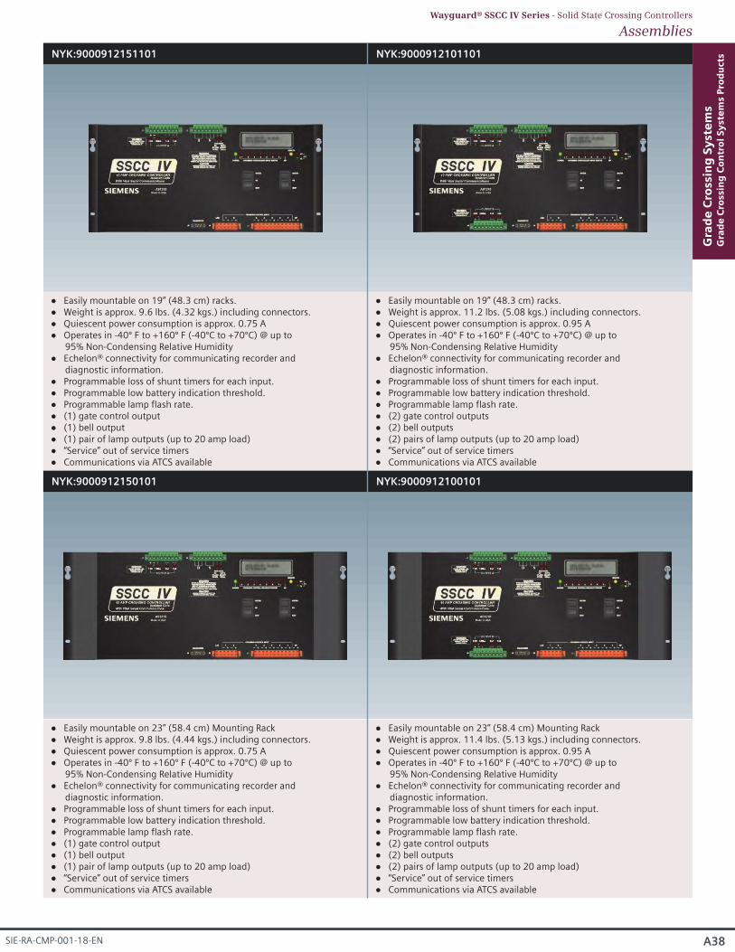
NYK:9000912151101 NYK:9000912101101
NYK:9000912150101 NYK:9000912100101
Easily mountable on 19” (48.3 cm) racks. Weight is approx. 9.6 lbs. (4.32 kgs.) including connectors. Quiescent power consumption is approx. 0.75 A Operates in -40º F to +160º F (-40ºC to +70ºC) @ up to
95% Non-Condensing Relative Humidity Echelon® connectivity for communicating recorder and
diagnostic information. Programmable loss of shunt timers for each input. Programmable low battery indication threshold. Programmable lamp flash rate. (1) gate control output (1) bell output (1) pair of lamp outputs (up to 20 amp load) “Service” out of service timers Communications via ATCS available
Easily mountable on 19” (48.3 cm) racks. Weight is approx. 11.2 lbs. (5.08 kgs.) including connectors. Quiescent power consumption is approx. 0.95 A Operates in -40º F to +160º F (-40ºC to +70ºC) @ up to
95% Non-Condensing Relative Humidity Echelon® connectivity for communicating recorder and
diagnostic information. Programmable loss of shunt timers for each input. Programmable low battery indication threshold. Programmable lamp flash rate. (2) gate control outputs (2) bell outputs (2) pairs of lamp outputs (up to 20 amp load) “Service” out of service timers Communications via ATCS available
Easily mountable on 23” (58.4 cm) Mounting Rack Weight is approx. 9.8 lbs. (4.44 kgs.) including connectors. Quiescent power consumption is approx. 0.75 A Operates in -40º F to +160º F (-40ºC to +70ºC) @ up to
95% Non-Condensing Relative Humidity Echelon® connectivity for communicating recorder and
diagnostic information. Programmable loss of shunt timers for each input. Programmable low battery indication threshold. Programmable lamp flash rate. (1) gate control output (1) bell output (1) pair of lamp outputs (up to 20 amp load) “Service” out of service timers Communications via ATCS available
Easily mountable on 23” (58.4 cm) Mounting Rack Weight is approx. 11.4 lbs. (5.13 kgs.) including connectors. Quiescent power consumption is approx. 0.95 A Operates in -40º F to +160º F (-40ºC to +70ºC) @ up to
95% Non-Condensing Relative Humidity Echelon® connectivity for communicating recorder and
diagnostic information. Programmable loss of shunt timers for each input. Programmable low battery indication threshold. Programmable lamp flash rate. (2) gate control outputs (2) bell outputs (2) pairs of lamp outputs (up to 20 amp load) “Service” out of service timers Communications via ATCS available
A38
Gra
de
Cro
ssin
g S
yst
em
sG
rad
e C
ross
ing
Co
ntr
ol
Sy
ste
ms
Pro
du
cts
SIE-RA-CMP-001-18-EN
AssembliesWayguard® SSCC IV Series - Solid State Crossing Controllers
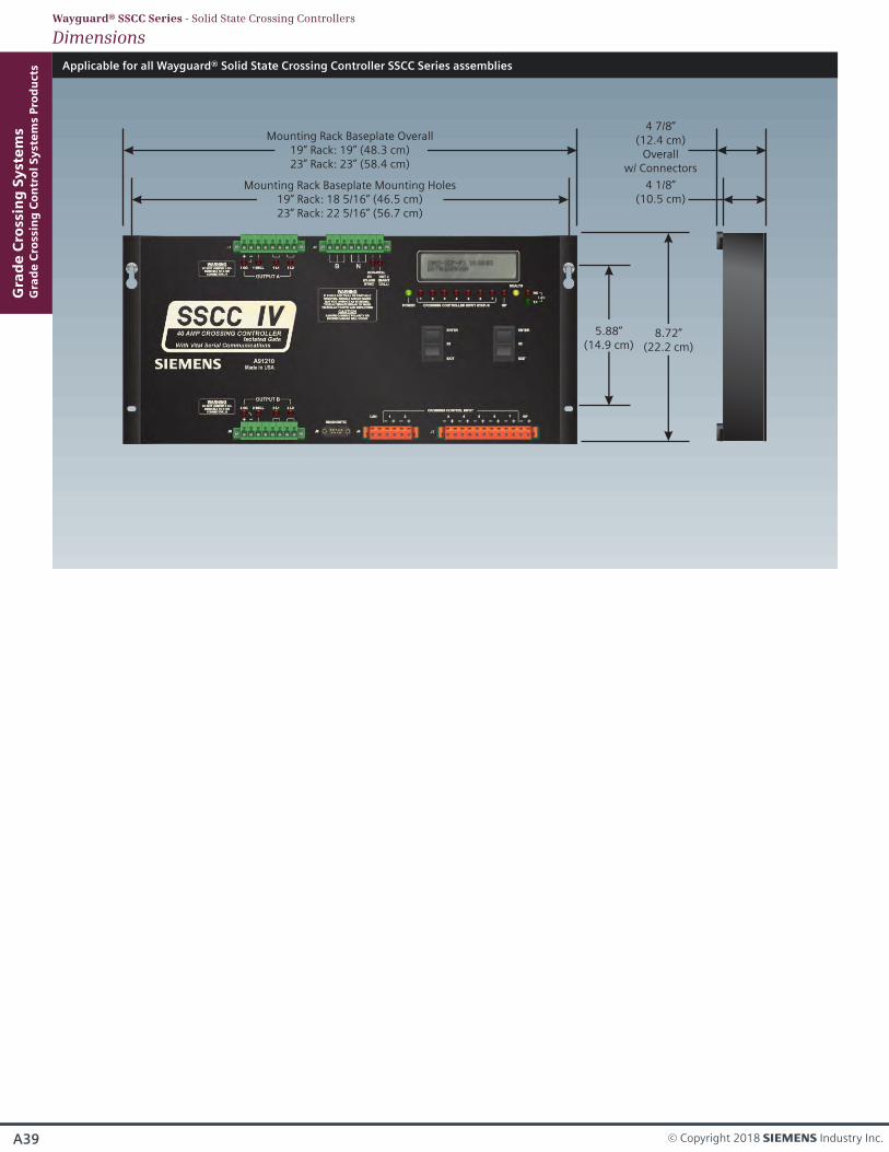
Applicable for all Wayguard® Solid State Crossing Controller SSCC Series assemblies
Mounting Rack Baseplate Overall19” Rack: 19” (48.3 cm)23” Rack: 23” (58.4 cm)
8.72”(22.2 cm)
5.88”(14.9 cm)
Mounting Rack Baseplate Mounting Holes19” Rack: 18 5/16” (46.5 cm)23” Rack: 22 5/16” (56.7 cm)
4 7/8”(12.4 cm)
Overallw/ Connectors
4 1/8”(10.5 cm)
A39
Gra
de
Cro
ssin
g S
yst
em
sG
rad
e C
ross
ing
Co
ntr
ol
Sy
ste
ms
Pro
du
cts
© Copyright 2018 s Industry Inc.
DimensionsWayguard® SSCC Series - Solid State Crossing Controllers
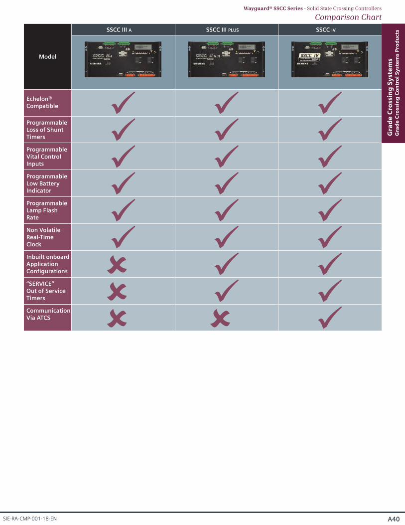
ProgrammableLamp FlashRate
Inbuilt onboardApplicationConfigurations
Non VolatileReal-TimeClock
“SERVICE”Out of ServiceTimers
CommunicationVia ATCS
SSCC III A SSCC III PLUS SSCC IV
Model
Echelon®Compatible
ProgrammableLoss of ShuntTimers ProgrammableVital ControlInputs ProgrammableLow BatteryIndicator
A40
Gra
de
Cro
ssin
g S
yst
em
sG
rad
e C
ross
ing
Co
ntr
ol
Sy
ste
ms
Pro
du
cts
SIE-RA-CMP-001-18-EN
Comparison ChartWayguard® SSCC Series - Solid State Crossing Controllers
A41 © Copyright 2018 s Industry Inc.
Gra
de
Cro
ssin
g S
yst
em
sG
rad
e C
ross
ing
Co
ntr
ol
Sy
ste
ms
Pro
du
cts
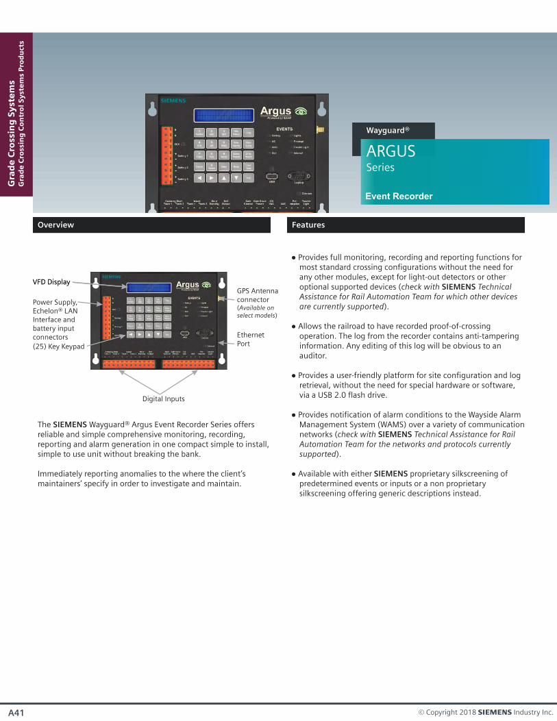
ARGUSSeries
Wayguard®
The SIEMENS Wayguard® Argus Event Recorder Series offers reliable and simple comprehensive monitoring, recording, reporting and alarm generation in one compact simple to install, simple to use unit without breaking the bank.
Immediately reporting anomalies to the where the client’s maintainers’ specify in order to investigate and maintain.
Event Recorder
Provides full monitoring, recording and reporting functions for most standard crossing configurations without the need for any other modules, except for light-out detectors or other optional supported devices (check with SIEMENS Technical Assistance for Rail Automation Team for which other devices are currently supported).
Allows the railroad to have recorded proof-of-crossing operation. The log from the recorder contains anti-tampering information. Any editing of this log will be obvious to an auditor.
Provides a user-friendly platform for site configuration and log retrieval, without the need for special hardware or software, via a USB 2.0 flash drive.
Provides notification of alarm conditions to the Wayside Alarm Management System (WAMS) over a variety of communication networks (check with SIEMENS Technical Assistance for Rail Automation Team for the networks and protocols currently supported).
Available with either SIEMENS proprietary silkscreening of predetermined events or inputs or a non proprietary silkscreening offering generic descriptions instead.
Digital Inputs
(25) Key Keypad
VFD DisplayGPS Antennaconnector(Available onselect models)
EthernetPort
VFD Display
Power Supply,Echelon® LANInterface andbattery inputconnectors
Overview
Features
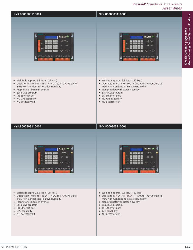
NYK:8000803110001 NYK:8000803110003
NYK:8000803110004 NYK:8000803110006
Weight is approx. 2.8 lbs. (1.27 kgs.) Operates in -40º F to +160º F (-40ºC to +70ºC) @ up to
95% Non-Condensing Relative Humidity Proprietary silkscreen overlay Basic CDL program (1) Ethernet port NO GPS capability NO accessory kit
Weight is approx. 2.8 lbs. (1.27 kgs.) Operates in -40º F to +160º F (-40ºC to +70ºC) @ up to
95% Non-Condensing Relative Humidity Non proprietary silkscreen overlay Basic CDL program (1) Ethernet port NO GPS capability NO accessory kit
Weight is approx. 2.8 lbs. (1.27 kgs.) Operates in -40º F to +160º F (-40ºC to +70ºC) @ up to
95% Non-Condensing Relative Humidity Proprietary silkscreen overlay Basic CDL program (1) Ethernet port GPS capability NO accessory kit
Weight is approx. 2.8 lbs. (1.27 kgs.) Operates in -40º F to +160º F (-40ºC to +70ºC) @ up to
95% Non-Condensing Relative Humidity Non proprietary silkscreen overlay Basic CDL program (1) Ethernet port GPS capability NO accessory kit
A42
Gra
de
Cro
ssin
g S
yst
em
sG
rad
e C
ross
ing
Co
ntr
ol
Sy
ste
ms
Pro
du
cts
SIE-RA-CMP-001-18-EN
AssembliesWayguard® Argus Series - Event Recorders
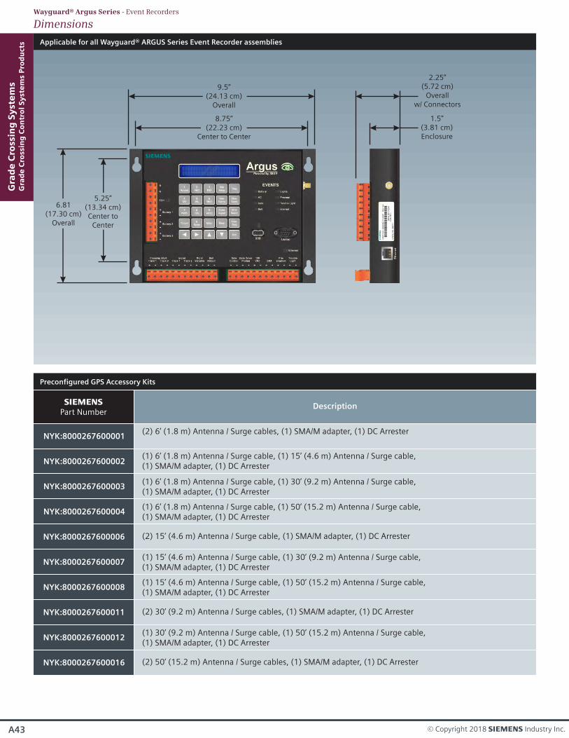
Applicable for all Wayguard® ARGUS Series Event Recorder assemblies
9.5”(24.13 cm)
Overall
6.81(17.30 cm)
Overall
5.25”(13.34 cm)Center to
Center
8.75”(22.23 cm)
Center to Center
2.25”(5.72 cm)
Overallw/ Connectors
1.5”(3.81 cm)Enclosure
Gra
de
Cro
ssin
g S
yst
em
sG
rad
e C
ross
ing
Co
ntr
ol
Sy
ste
ms
Pro
du
cts
A43 © Copyright 2018 s Industry Inc.
Preconfigured GPS Accessory Kits
NYK:8000267600001
s Part Number
(2) 6’ (1.8 m) Antenna / Surge cables, (1) SMA/M adapter, (1) DC Arrester
Description
NYK:8000267600002(1) 6’ (1.8 m) Antenna / Surge cable, (1) 15’ (4.6 m) Antenna / Surge cable,(1) SMA/M adapter, (1) DC Arrester
NYK:8000267600003(1) 6’ (1.8 m) Antenna / Surge cable, (1) 30’ (9.2 m) Antenna / Surge cable, (1) SMA/M adapter, (1) DC Arrester
NYK:8000267600004(1) 6’ (1.8 m) Antenna / Surge cable, (1) 50’ (15.2 m) Antenna / Surge cable, (1) SMA/M adapter, (1) DC Arrester
(2) 15’ (4.6 m) Antenna / Surge cable, (1) SMA/M adapter, (1) DC ArresterNYK:8000267600006
(1) 15’ (4.6 m) Antenna / Surge cable, (1) 30’ (9.2 m) Antenna / Surge cable, (1) SMA/M adapter, (1) DC Arrester
NYK:8000267600007
(1) 15’ (4.6 m) Antenna / Surge cable, (1) 50’ (15.2 m) Antenna / Surge cable, (1) SMA/M adapter, (1) DC Arrester
NYK:8000267600008
(2) 30’ (9.2 m) Antenna / Surge cables, (1) SMA/M adapter, (1) DC ArresterNYK:8000267600011
(1) 30’ (9.2 m) Antenna / Surge cable, (1) 50’ (15.2 m) Antenna / Surge cable, (1) SMA/M adapter, (1) DC Arrester
NYK:8000267600012
(2) 50’ (15.2 m) Antenna / Surge cables, (1) SMA/M adapter, (1) DC ArresterNYK:8000267600016
DimensionsWayguard® Argus Series - Event Recorders
A44
Gra
de
Cro
ssin
g S
yst
em
sG
rad
e C
ross
ing
Co
ntr
ol
Sy
ste
ms
Pro
du
cts
SIE-RA-CMP-001-18-EN
Wayguard®
ACM 200Series
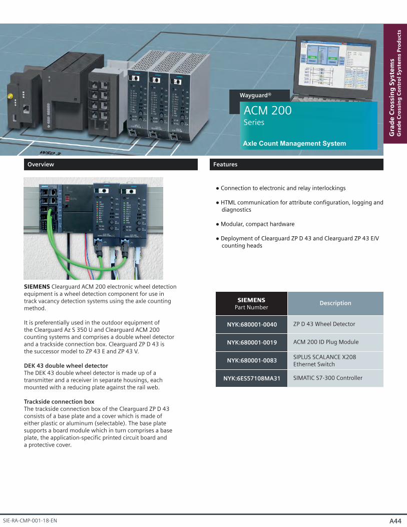
NYK:680001-0040
s Part Number
ZP D 43 Wheel Detector
Description
NYK:680001-0019 ACM 200 ID Plug Module
NYK:680001-0083SIPLUS SCALANCE X208Ethernet Switch
NYK:6ES57108MA31 SIMATIC S7-300 Controller
Axle Count Management System
SIEMENS Clearguard ACM 200 electronic wheel detectionequipment is a wheel detection component for use intrack vacancy detection systems using the axle countingmethod.
It is preferentially used in the outdoor equipment ofthe Clearguard Az S 350 U and Clearguard ACM 200counting systems and comprises a double wheel detectorand a trackside connection box. Clearguard ZP D 43 isthe successor model to ZP 43 E and ZP 43 V.
DEK 43 double wheel detectorThe DEK 43 double wheel detector is made up of atransmitter and a receiver in separate housings, eachmounted with a reducing plate against the rail web.
Trackside connection boxThe trackside connection box of the Clearguard ZP D 43consists of a base plate and a cover which is made ofeither plastic or aluminum (selectable). The base platesupports a board module which in turn comprises a baseplate, the application-specific printed circuit board anda protective cover.
Connection to electronic and relay interlockings
HTML communication for attribute configuration, logging and diagnostics
Modular, compact hardware
Deployment of Clearguard ZP D 43 and Clearguard ZP 43 E/V counting heads
Overview
Features
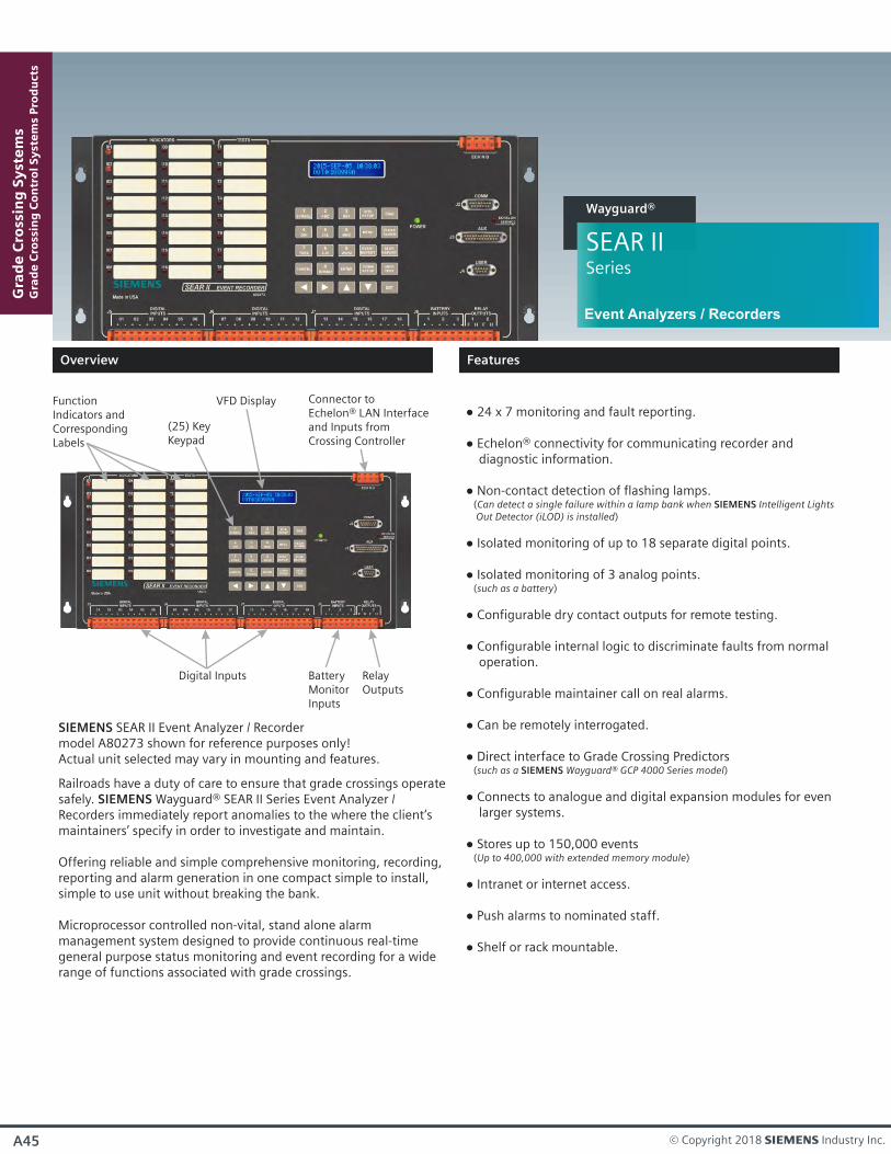
FunctionIndicators and CorrespondingLabels
BatteryMonitorInputs
Digital Inputs
(25) KeyKeypad
SIEMENS SEAR II Event Analyzer / Recorder model A80273 shown for reference purposes only!Actual unit selected may vary in mounting and features.
24 x 7 monitoring and fault reporting.
Echelon® connectivity for communicating recorder and diagnostic information.
Non-contact detection of flashing lamps. (Can detect a single failure within a lamp bank when SIEMENS Intelligent Lights Out Detector (iLOD) is installed)
Isolated monitoring of up to 18 separate digital points.
Isolated monitoring of 3 analog points. (such as a battery)
Configurable dry contact outputs for remote testing.
Configurable internal logic to discriminate faults from normal operation.
Configurable maintainer call on real alarms.
Can be remotely interrogated.
Direct interface to Grade Crossing Predictors (such as a SIEMENS Wayguard® GCP 4000 Series model)
Connects to analogue and digital expansion modules for even larger systems.
Stores up to 150,000 events (Up to 400,000 with extended memory module)
Intranet or internet access.
Push alarms to nominated staff.
Shelf or rack mountable.
RelayOutputs
Connector toEchelon® LAN Interfaceand Inputs from Crossing Controller
VFD Display
Railroads have a duty of care to ensure that grade crossings operatesafely. SIEMENS Wayguard® SEAR II Series Event Analyzer / Recorders immediately report anomalies to the where the client’s maintainers’ specify in order to investigate and maintain.
Offering reliable and simple comprehensive monitoring, recording, reporting and alarm generation in one compact simple to install, simple to use unit without breaking the bank.
Microprocessor controlled non-vital, stand alone alarm management system designed to provide continuous real-time general purpose status monitoring and event recording for a wide range of functions associated with grade crossings.
Gra
de
Cro
ssin
g S
yst
em
sG
rad
e C
ross
ing
Co
ntr
ol
Sy
ste
ms
Pro
du
cts
A45 © Copyright 2018 s Industry Inc.
SEAR IISeries
Wayguard®
Event Analyzers / Recorders
Overview
Features
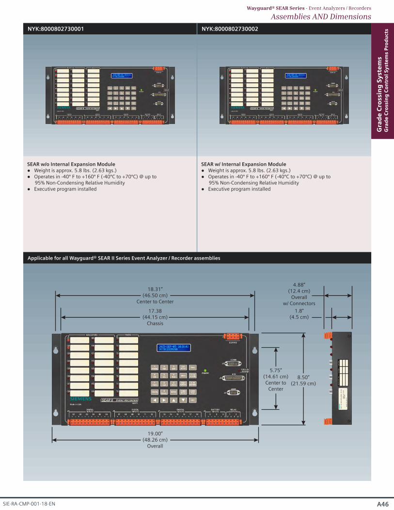
NYK:8000802730001 NYK:8000802730002
SEAR w/o Internal Expansion Module Weight is approx. 5.8 lbs. (2.63 kgs.) Operates in -40º F to +160º F (-40ºC to +70ºC) @ up to
95% Non-Condensing Relative Humidity Executive program installed
SEAR w/ Internal Expansion Module Weight is approx. 5.8 lbs. (2.63 kgs.) Operates in -40º F to +160º F (-40ºC to +70ºC) @ up to
95% Non-Condensing Relative Humidity Executive program installed
A46
Gra
de
Cro
ssin
g S
yst
em
sG
rad
e C
ross
ing
Co
ntr
ol
Sy
ste
ms
Pro
du
cts
SIE-RA-CMP-001-18-EN
Assemblies AND DimensionsWayguard® SEAR Series - Event Analyzers / Recorders
Applicable for all Wayguard® SEAR II Series Event Analyzer / Recorder assemblies
18.31”(46.50 cm)
Center to Center
8.50”(21.59 cm)
5.75”(14.61 cm)Center to
Center
17.38 (44.15 cm)
Chassis
4.88”(12.4 cm)
Overallw/ Connectors
1.8”(4.5 cm)
19.00”(48.26 cm)
Overall
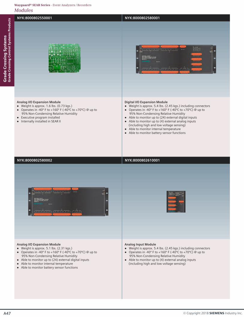
NYK:8000802550001 NYK:8000802580001
Analog I/O Expansion Module Weight is approx. 1.6 lbs. (0.73 kgs.)
Operates in -40º F to +160º F (-40ºC to +70ºC) @ up to 95% Non-Condensing Relative Humidity
Executive program installed Internally installed in SEAR II
Digital I/O Expansion Module Weight is approx. 5.4 lbs. (2.45 kgs.) including connectors Operates in -40º F to +160º F (-40ºC to +70ºC) @ up to
95% Non-Condensing Relative Humidity Able to monitor up to (24) external digital inputs Able to monitor up to (4) external analog inputs
(including high and low voltage sensing) Able to monitor internal temperature Able to monitor battery sensor functions
NYK:8000802580002
Analog I/O Expansion Module Weight is approx. 5.1 lbs. (2.31 kgs.) Operates in -40º F to +160º F (-40ºC to +70ºC) @ up to
95% Non-Condensing Relative Humidity Able to monitor up to (24) external digital inputs Able to monitor internal temperature Able to monitor battery sensor functions
NYK:8000802610001
Analog Input Module Weight is approx. 5.4 lbs. (2.45 kgs.) including connectors Operates in -40º F to +160º F (-40ºC to +70ºC) @ up to
95% Non-Condensing Relative Humidity Able to monitor up to (4) external analog inputs
(including high and low voltage sensing)
Gra
de
Cro
ssin
g S
yst
em
sG
rad
e C
ross
ing
Co
ntr
ol
Sy
ste
ms
Pro
du
cts
A47 © Copyright 2018 s Industry Inc.
ModulesWayguard® SEAR Series - Event Analyzers / Recorders
A48
Gra
de
Cro
ssin
g S
yst
em
sG
rad
e C
ross
ing
Co
ntr
ol
Sy
ste
ms
Pro
du
cts
SIE-RA-CMP-001-18-EN
ModulesWayguard® SEAR Series - Event Analyzers / Recorders
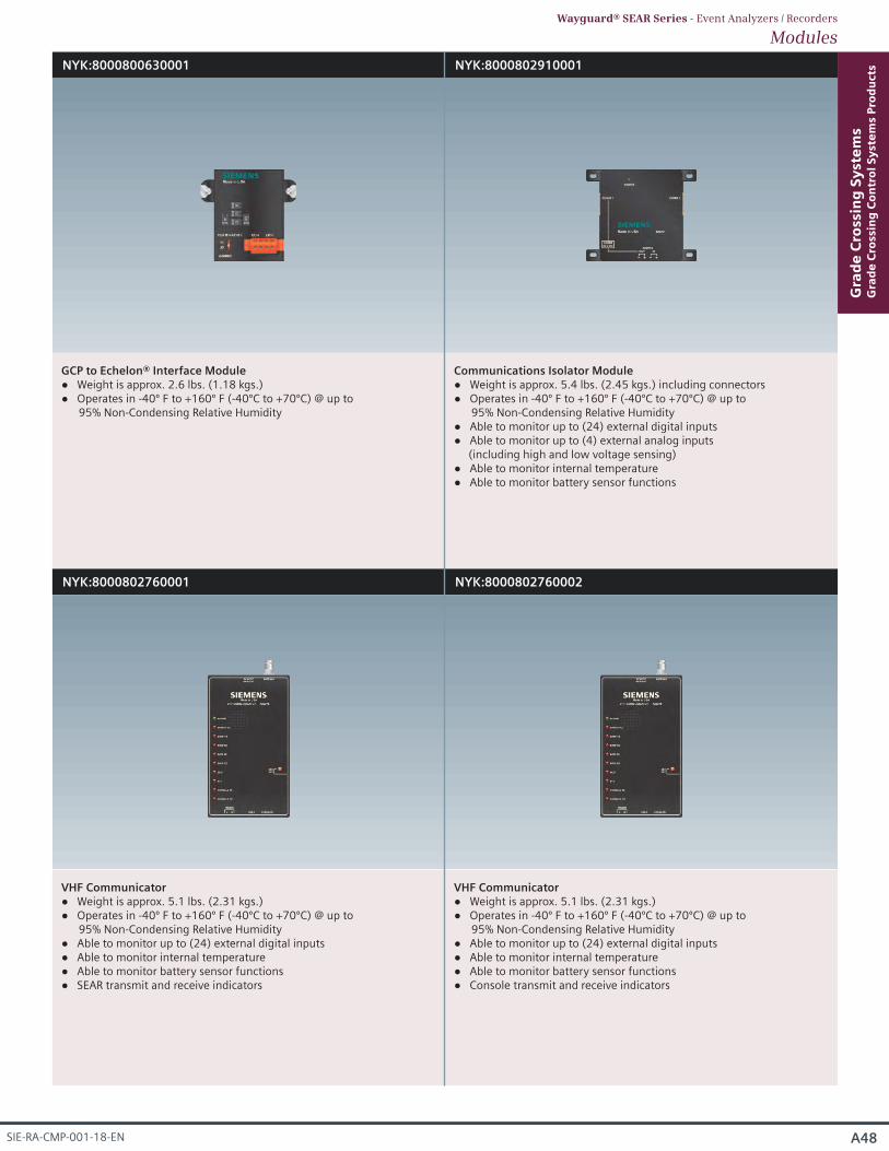
NYK:8000800630001 NYK:8000802910001
GCP to Echelon® Interface Module Weight is approx. 2.6 lbs. (1.18 kgs.) Operates in -40º F to +160º F (-40ºC to +70ºC) @ up to
95% Non-Condensing Relative Humidity
Communications Isolator Module Weight is approx. 5.4 lbs. (2.45 kgs.) including connectors Operates in -40º F to +160º F (-40ºC to +70ºC) @ up to
95% Non-Condensing Relative Humidity Able to monitor up to (24) external digital inputs Able to monitor up to (4) external analog inputs
(including high and low voltage sensing) Able to monitor internal temperature Able to monitor battery sensor functions
NYK:8000802760001
VHF Communicator Weight is approx. 5.1 lbs. (2.31 kgs.)
Operates in -40º F to +160º F (-40ºC to +70ºC) @ up to 95% Non-Condensing Relative Humidity
Able to monitor up to (24) external digital inputs Able to monitor internal temperature Able to monitor battery sensor functions SEAR transmit and receive indicators
NYK:8000802760002
VHF Communicator Weight is approx. 5.1 lbs. (2.31 kgs.)
Operates in -40º F to +160º F (-40ºC to +70ºC) @ up to 95% Non-Condensing Relative Humidity
Able to monitor up to (24) external digital inputs Able to monitor internal temperature Able to monitor battery sensor functions Console transmit and receive indicators
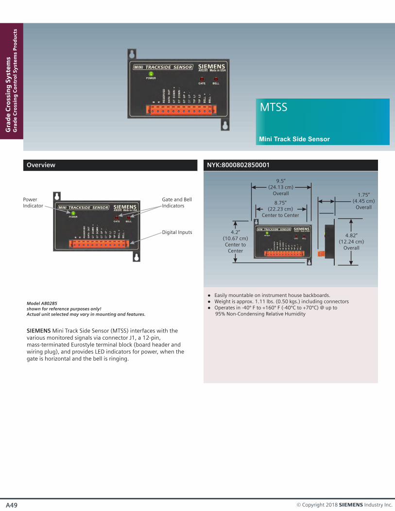
Easily mountable on instrument house backboards. Weight is approx. 1.11 lbs. (0.50 kgs.) including connectors Operates in -40º F to +160º F (-40ºC to +70ºC) @ up to
95% Non-Condensing Relative Humidity
9.5”(24.13 cm)
Overall
4.82”(12.24 cm)
Overall
4.2”(10.67 cm)Center to
Center
8.75”(22.23 cm)
Center to Center
1.75”(4.45 cm)
Overall
A49 © Copyright 2018 s Industry Inc.
Overview
Model A80285shown for reference purposes only!Actual unit selected may vary in mounting and features.
Gra
de
Cro
ssin
g S
yst
em
sG
rad
e C
ross
ing
Co
ntr
ol
Sy
ste
ms
Pro
du
cts
MTSS
SIEMENS Mini Track Side Sensor (MTSS) interfaces with the various monitored signals via connector J1, a 12-pin, mass-terminated Eurostyle terminal block (board header and wiring plug), and provides LED indicators for power, when the gate is horizontal and the bell is ringing.
Mini Track Side Sensor
Gate and BellIndicators
Digital Inputs
PowerIndicator
NYK:8000802850001
Overview
Model A80271shown for reference purposes only!Actual unit selected may vary in mounting and features.
Gra
de
Cro
ssin
g S
yst
em
sG
rad
e C
ross
ing
Co
ntr
ol
Sy
ste
ms
Pro
du
cts
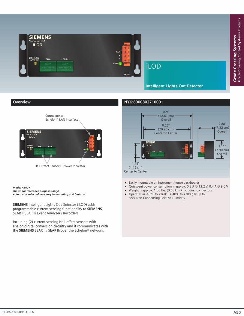
iLOD
SIEMENS Intelligent Lights Out Detector (iLOD) adds programmable current sensing functionality to SIEMENS SEAR II/SEAR IIi Event Analyzer / Recorders. Including (2) current sensing Hall-effect sensors with analog-digital conversion circuitry and it communicates with the SIEMENS SEAR II / SEAR IIi over the Echelon® network.
Intelligent Lights Out Detector
NYK:8000802710001
A50SIE-RA-CMP-001-18-EN
Easily mountable on instrument house backboards. Quiescent power consumption is approx. 0.3 A @ 13.2 V, 0.4 A @ 9.0 V Weight is approx. 1.50 lbs. (0.68 kgs.) including connectors Operates in -40º F to +160º F (-40ºC to +70ºC) @ up to
95% Non-Condensing Relative Humidity
8.9”(22.61 cm)
Overall
1.75”(4.45 cm)
Center to Center
8.25”(20.96 cm)
Center to Center
2.88”(7.32 cm)
Overall
3.11”
(7.90 cm)Overall
Connector toEchelon® LAN Interface
Hall Effect Sensors Power Indicator
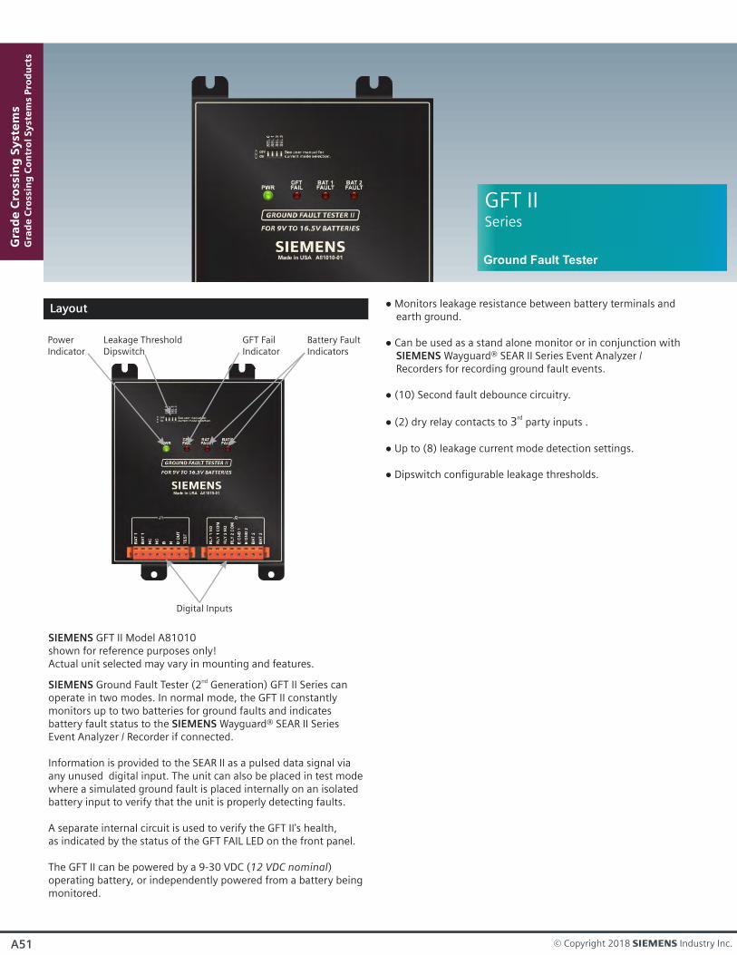
Layout
SIEMENS GFT II Model A81010shown for reference purposes only!Actual unit selected may vary in mounting and features.
SIEMENS Ground Fault Tester (2 Generation) GFT II Series can nd
operate in two modes. In normal mode, the GFT II constantly monitors up to two batteries for ground faults and indicates battery fault status to the SIEMENS Wayguard® SEAR II Series Event Analyzer / Recorder if connected.
Information is provided to the SEAR II as a pulsed data signal via any unused digital input. The unit can also be placed in test mode where a simulated ground fault is placed internally on an isolated battery input to verify that the unit is properly detecting faults.
A separate internal circuit is used to verify the GFT II's health, as indicated by the status of the GFT FAIL LED on the front panel.
The GFT II can be powered by a 9-30 VDC (12 VDC nominal) operating battery, or independently powered from a battery being monitored.
Digital Inputs
Monitors leakage resistance between battery terminals and earth ground.
Can be used as a stand alone monitor or in conjunction with SIEMENS Wayguard® SEAR II Series Event Analyzer / Recorders for recording ground fault events.
(10) Second fault debounce circuitry.
(2) dry relay contacts to party inputs .rd
3
Up to (8) leakage current mode detection settings.
Dipswitch configurable leakage thresholds.
PowerIndicator
GFT FailIndicator
Battery FaultIndicators
Leakage ThresholdDipswitch
Gra
de
Cro
ssin
g S
yst
em
sG
rad
e C
ross
ing
Co
ntr
ol
Sy
ste
ms
Pro
du
cts
A51 © Copyright 2018 s Industry Inc.
GFT IISeries
Ground Fault Tester
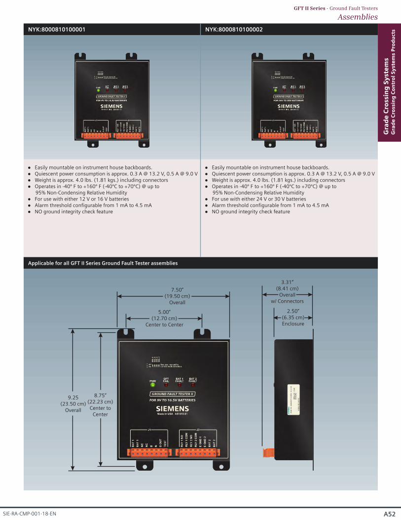
AssembliesGFT II Series - Ground Fault Testers
NYK:8000810100001 NYK:8000810100002
Easily mountable on instrument house backboards. Quiescent power consumption is approx. 0.3 A @ 13.2 V, 0.5 A @ 9.0 V Weight is approx. 4.0 lbs. (1.81 kgs.) including connectors Operates in -40º F to +160º F (-40ºC to +70ºC) @ up to
95% Non-Condensing Relative Humidity For use with either 12 V or 16 V batteries Alarm threshold configurable from 1 mA to 4.5 mA NO ground integrity check feature
Easily mountable on instrument house backboards. Quiescent power consumption is approx. 0.3 A @ 13.2 V, 0.5 A @ 9.0 V Weight is approx. 4.0 lbs. (1.81 kgs.) including connectors Operates in -40º F to +160º F (-40ºC to +70ºC) @ up to
95% Non-Condensing Relative Humidity For use with either 24 V or 30 V batteries Alarm threshold configurable from 1 mA to 4.5 mA NO ground integrity check feature
A52
Gra
de
Cro
ssin
g S
yst
em
sG
rad
e C
ross
ing
Co
ntr
ol
Sy
ste
ms
Pro
du
cts
SIE-RA-CMP-001-18-EN
Applicable for all GFT II Series Ground Fault Tester assemblies
7.50”(19.50 cm)
Overall
9.25(23.50 cm)
Overall
8.75”(22.23 cm)Center to
Center
5.00”(12.70 cm)
Center to Center
3.31”(8.41 cm)
Overallw/ Connectors
2.50”(6.35 cm)Enclosure