graded requirements under bs en 62676 standards for cctv · installers of cctv and other interested...
TRANSCRIPT

Graded requirements under
BS EN 62676 Standards for CCTV – a technical guide for installers, specifiers and manufacturers
Issue 2
August 2016
For other information please contact:
British Security Industry Association
t: 0845 389 3889
www.bsia.co.uk
Form No. 218 © This document is the copyright of the BSIA and is not to be reproduced without the written consent of the copyright owner.
Issue 2| August 2016 Page 2 of 35
Contents
1 SCOPE 5
2 REFERENCED DOCUMENTS 5
2.1 Referenced Standards 5
2.2 Regulations 6
3 DEFINITIONS AND ABBREVIATIONS 6
3.1 Terms and Definitions 6
3.2 Abbreviations 6
4 HOW TO USE THIS GUIDE 6
5 HOW DOES THE CUSTOMER BENEFIT BY THE USE OF GRADING 7
6 GRADE SELECTION 8
6.1 General 8
6.2 When is Grading necessary? 10
6.2.1 General 10
6.2.2 Primary Mitigation 10
6.3 How is the grading of a system defined? 11
6.3.1 General 11
6.3.2 Overall Grade and Consistent Use 11
6.3.3 Tamper Protection and Detection Requirements 12
6.3.4 Using the OR or SDP to modify grade requirements 12
6.4 Summary of Grading 13
7 HOW TO RECORD GRADING OF SYSTEMS 13
7.1 Recording of the grade in CCTV Documentation 13
7.2 Example 1 14
7.3 Example 2 15
7.4 Example 3 16
8 SUMMARY OF THE GRADED FUNCTIONS 17
Issue 2| August 2016 Page 3 of 35
9 COMMENTARY ON THE REQUIREMENTS BY FUNCTION 18
9.1 Introduction 18
9.2 Common Interconnections 18
9.3 Storage 19
9.4 Archiving and Backup 20
9.5 Alarm Related Information 20
9.6 System Logs 21
9.7 Backup and Restore of System 22
9.8 Repetitive Failure Notification 23
9.9 Image Handling Device PSU Monitoring 23
9.10 Image Buffer Holding Time 24
9.11 Essential Function Device Failure Notification Time 24
9.12 Monitoring of Interconnections 25
9.13 Tamper Detection 25
9.14 Authorisation Code Requirements 26
9.15 Time Synchronisation 27
9.16 Data Labelling 27
9.17 Data Authentication 27
9.18 Export / Copy Authentication 28
9.19 Data (manipulation) protection 28
10 GRADED REQUIREMENTS – SUMMARY 29
11 GUIDANCE FOR MANUFACTURERS 33
11.1 Introduction 33
11.2 System v Component 33
11.3 Graded Functions 34
11.4 Tamper Protection 35
11.5 Summary 35
Issue 2| August 2016 Page 4 of 35
Introduction The BS EN 62676 series of standards are the first standards for CCTV video surveillance that will be used
to any significant extent in the UK and include the use of security grading. This guide is intended to assist
installers of CCTV and other interested parties to understand how a choice of grade is to be made and then
used to determine the design requirements of a CCTV system.
It is important to understand that the majority of requirements given by the BS EN 62676 series of
standards are not grade dependent. This guide deals only with the minority of requirements that are grade
dependent. Most of these are to be found in BS EN 62676-1-1 but there are a few in BS EN 62676-1-2 (the
names of the standards can be found in 2.1).
The approach to grading given in the BS EN 62676 series of standards is intended to allow for flexibility to
overcome problems that a system designer may face. It is not intended to be complicated but the flexibility
can give the appearance of complexity. Having an understanding of the flexible possibilities will benefit
system designers whether they choose to use them or not.
A summary of the key points about grading detailed in this document are:
• System designers should choose the simplest approach that will work.
• The recommended approach is to choose a grade of system and apply that single grade throughout
the system.
• The grading will affect the protection level and restriction of access to the system.
• It is the functions of the CCTV system that are graded rather than each component.
• Grading of a system does not determine the quality of the images captured by the system. BS EN 62676-4
includes requirements and recommendations that will determine the quality of image recording.
• The chosen grade(s) should be recorded in the Operational Requirement or System Design Proposal.
• Where use of a single grade for all system functions is not practical the standard permits the grading to
be divided up by function. 18 Functions are described in the standard.
• Additional flexibility can be obtained by documenting specific requirements in the Operational
Requirements or System Design Proposal.
Note: For security practitioners with a knowledge of intruder alarms (as installed under the PD 6662
scheme) it is important to note that the way that grading is described in the CCTV standards is not the same
and confusion may arise if the differences are not understood. Additionally for intruder systems the installer’s
life is made easy by the existence of component standards. For example an installer seeking a Grade 3
passive infra-red detector simply looks for a device that a manufacturer states meets the requirements of
the associated standard. This is not the case for CCTV. There are currently no standards for CCTV system
components specifying differences between their requirements at each grade.

Issue 2| August 2016 Page 5 of 35
1. Scope These guidelines are for use in conjunction with the BS EN 62676 series of standards for “Video
Surveillance Systems for Use in Security Applications”. In particular they give guidance to the requirements
in BS EN 62676-1-1 “System Requirements – General”.
Note: The BS EN 62676 series of standards uses the term Video Surveillance System (VSS) for systems
commonly known in the UK as CCTV (Closed Circuit Television) systems. Although CCTV is no longer
technically correct in all situations the terms may be used interchangeably.
It is not mandatory to use Security Grading when installing systems to meet the standard but the use of
Grading can give benefit and simplify matters.
Grading of a system does not specifically determine the quality of the images captured by the system
although implementation of a higher grade may coincidentally result in an improvement. The grading will
affect the protection level and restriction of access to the system.
BS EN 62676-4 includes recommendations that will determine the quality of image recording.
2. Referenced Documents 2.1. Referenced Standards
The following referenced documents are indispensable for the application of this document.
BS EN 62676 series Video surveillance systems for use in security applications
BS EN 62676-1-1 Video System Requirements
BS EN 62676-1-2 Video Transmission – General Video Transmission – Requirements
BS EN 62676-2-1 Video Transmission Protocols – General Requirements
BS EN 62676-2-2 Video Transmission Protocols – IP Interoperability implementation based on
HTTP and REST services
BS EN 62676-2-3 Video Transmission Protocols – IP Interoperability implementation based on
web services
BS EN 62676-3 Analog and Digital Video Interfaces
BS EN 62676-4 Application guidelines
Issue 2| August 2016 Page 6 of 35
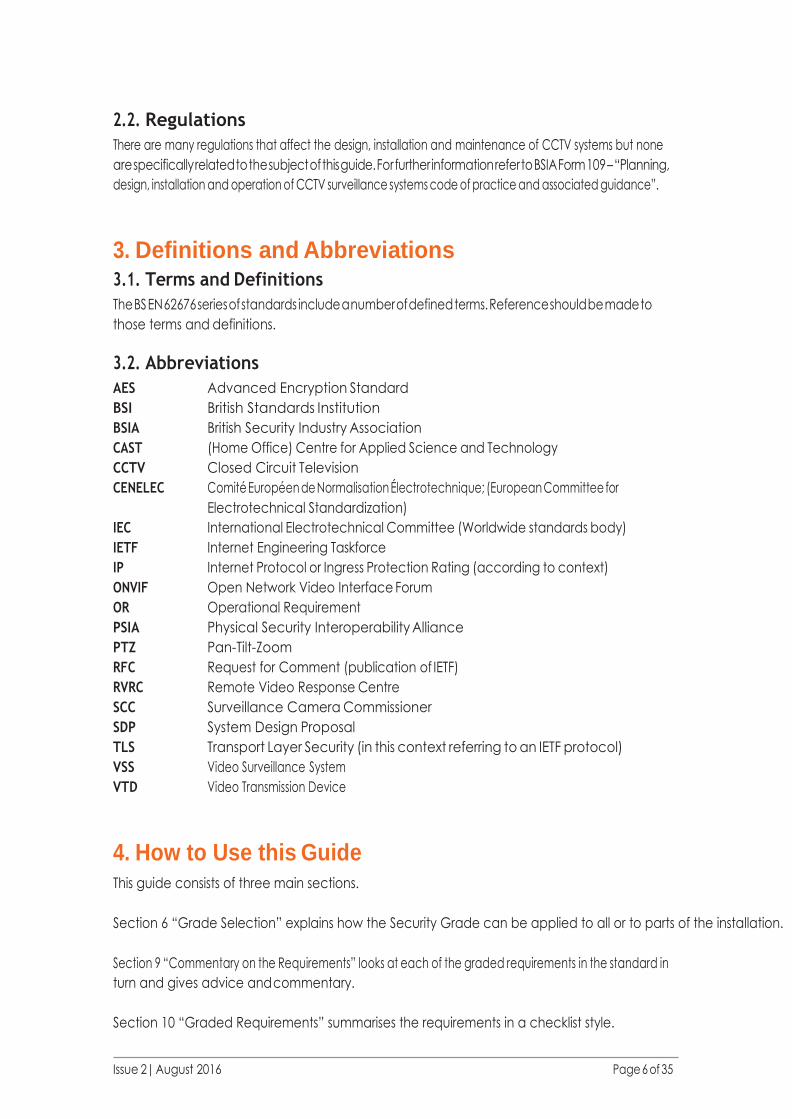
2.2. Regulations
There are many regulations that affect the design, installation and maintenance of CCTV systems but none
are specifically related to the subject of this guide. For further information refer to BSIA Form 109 – “Planning,
design, installation and operation of CCTV surveillance systems code of practice and associated guidance”.
3. Definitions and Abbreviations 3.1. Terms and Definitions
The BS EN 62676 series of standards include a number of defined terms. Reference should be made to
those terms and definitions.
3.2. Abbreviations
AES Advanced Encryption Standard
BSI British Standards Institution
BSIA British Security Industry Association
CAST (Home Office) Centre for Applied Science and Technology
CCTV Closed Circuit Television
CENELEC Comité Européen de Normalisation Électrotechnique; (European Committee for
Electrotechnical Standardization)
IEC International Electrotechnical Committee (Worldwide standards body)
IETF Internet Engineering Taskforce
IP Internet Protocol or Ingress Protection Rating (according to context)
ONVIF Open Network Video Interface Forum
OR Operational Requirement
PSIA Physical Security Interoperability Alliance
PTZ Pan-Tilt-Zoom
RFC Request for Comment (publication of IETF)
RVRC Remote Video Response Centre
SCC Surveillance Camera Commissioner
SDP System Design Proposal
TLS Transport Layer Security (in this context referring to an IETF protocol)
VSS Video Surveillance System
VTD Video Transmission Device
4. How to Use this Guide This guide consists of three main sections.
Section 6 “Grade Selection” explains how the Security Grade can be applied to all or to parts of the installation.
Section 9 “Commentary on the Requirements” looks at each of the graded requirements in the standard in
turn and gives advice and commentary.
Section 10 “Graded Requirements” summarises the requirements in a checklist style.

Issue 2| August 2016 Page 7 of 35
5. How does the customer benefit by the use of Grading This guide is primarily aimed at those wishing to understand the technical issues associated with grading
in terms of how the requirements differ by grade and also how to apply the graded requirements to the
system. BSIA have a separate guide (Form 217) that is intended to help customers of CCTV systems
understand the differences between an installation meeting the requirements of the BS EN 62676 series of
standards and other systems (e.g. systems that pre-dated those standards). This includes an overview of
the differences introduced by grading.
It is important that the customer realises that the choice of one grade over another will not affect the
quality of images obtained by the system. The use of different grades will however affect the robustness
and integrity of the system and its ability to continue to serve its purpose in the face of a criminal attack or
likely fault conditions.
The factors that are affected by the grade choice are indicated by the function titles in section 6.3.1 and
section 8.
As can be seen by the table in section 8, the majority of differences between system requirements are
associated with the step from Grade 2 to Grade 3. 13 of the 18 functions have identical requirements in
Grades 1 and 2 and 9 of the 18 are the same in Grades 3 and 4.
BS EN 62676-4 describes how the selection of security grades should be based on a risk assessment and the
system should be designed to mitigate the assessed risks. As the graded requirements primarily affect the
protection of the system itself then it is these aspects of a risk assessment that would determine the grade.
Therefore typically the grade will be the result of risks associated with threats and hazards such as:
• Vandalism or malicious attack on the CCTV system (without other criminal intent).
• Deliberate attack on the CCTV system (to assist with a crime).
• Environmental factors (e.g. flood damage to equipment, radio interference, lightning) and possible
power outages.
A higher risk will be associated with increased likelihoods of events. These may be indicated by:
• How attractive the criminal target is (e.g. valuables / persons at risk of kidnap).
• Lack of other security measures.
• Location in a high crime area or close to easy escape routes.
• Lack of occupancy.
• Easy public access.
• High crime history.
Issue 2| August 2016 Page 8 of 35
A higher risk will also be associated with a high impact. Many things might cause a high impact, including:
• Potentially high losses.
• Disruption to site activities.
Some aspects of the graded functions do not directly relate to the threat but are a consequence of the
risk assessment. An example is the need to preserve evidential data of good quality images. Although this
is unlikely to prevent a crime it is more likely to be important when a criminal will go to greater lengths to
protect their identity. This is associated with higher risks.
6. Grade Selection 6.1. General
The principle of grading in the BS EN 62676 series is to provide a short-hand way to simplify the
specification of system requirements, i.e. make it easy to specify functions by identifying the grade
dependant requirements as listed in the standard.
For practical purposes system designers should choose the simplest approach that will work. The following
sections outline the flexibility that is available but the recommended approach is to choose a grade of
system and apply that single grade throughout the system. Only when this will cause problems should it be
necessary to consider the alternative possibilities. Having an understanding of these possibilities will benefit
system designers whether they choose to use them or not.
Grading of a system does not specifically determine the quality of the images captured by the system
although implementation of a higher grade may coincidentally result in an improvement. The grading will
affect the level of protection and restriction of access to the system. A higher grade will give the
system greater integrity and resilience.
BS EN 62676-4 includes recommendations for installations that should be applied in conjunction with non-
graded requirements in BS EN 62676-1-1 to determine the quality of image recording.
The procedures to be followed for an installation are documented in BS EN 62676-4. This includes making
the choice of security grade(s). Once a decision has been made regarding the grading of the system BS EN
62676-1-1 includes the requirements that are specific to each grade.
With a surveillance camera system it is the functions of the system that are graded rather than each
component.
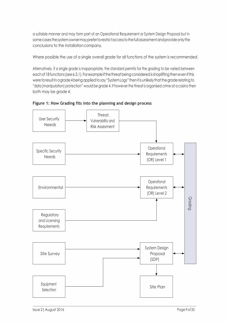
The choice of a grade should be made early in the process as part of the planning stage and the
consequences of this selection then influence work during the design stage. See Figure 1.
In choosing the grade or grades of a system it is expected that a threat, vulnerability and risk assessment
will have been performed to ensure the design of the system results in an installation that adequately
addresses the threats and reduces the security risks. The result of this activity should be recorded in
Issue 2| August 2016 Page 9 of 35
User Security
Needs
Threat,
Vulnerability and
Risk Assesment
a suitable manner and may form part of an Operational Requirement or System Design Proposal but in
some cases the system owner may prefer to restrict access to the full assessment and provide only the
conclusions to the installation company.
Where possible the use of a single overall grade for all functions of the system is recommended.
Alternatively, if a single grade is inappropriate, the standard permits for the grading to be varied between
each of 18 functions (see 6.3.1). For example if the threat being considered is shoplifting then even if this
were to result in a grade 4 being applied to say “System Logs” then it is unlikely that the grade relating to
“data (manipulation) protection” would be grade 4. If however the threat is organised crime at a casino then
both may be grade 4.
Figure 1: How Grading fits into the planning and design process
Equipment
Selection
System Design
Proposal
(SDP)
Site Survey
Regulatory
and Licensing
Requirements
Environmental
Specific Security
Needs
Site Plan
Operational
Requirements
(OR) Level 2 Gra
din
g
Operational
Requirements
(OR) Level 1

Issue 2| August 2016 Page 10 of 35
6.2. When is Grading necessary?
6.2.1. General
It is a requirement of the standards that “the system shall be given an overall grade” and “the identified
security grade requirements should be specified in the operational requirement (OR) and agreed by the
customer and system designer.” It is also stated that “where not specified the default security grade is 1.”
There is only one requirement (for labelling with date and time – see Table 11 of BS EN 62676-1-1) that is
listed as applying at Grade 1 but is not stated to be a requirement of all systems.
The standard does not require grading of systems to be performed in all cases (e.g. see 6.2.2) and it is
possible instead to define all requirements by way of the OR or system design proposal (SDP). The use
of grading may make it easier to define the system requirements and remove the need for individual
consideration of every requirement.
6.2.2. Primary Mitigation
BS EN 62676-1-1 says: “The security grades shall be applied, where VSS is identified as the primary mitiga-
tion of the risk.”
In this context “mitigation” means a measure that is put in place to reduce the consequences of a threat.
Security is not normally achieved using a single method of mitigation. Instead several methods are often
used in combination. For example:
– A good lock on a strong door may delay entry.
– An intruder alarm system may detect entry.
– A CCTV system may identify the offender (and so may act as a deterrent).
– A security officer responding to the alarm.
A CCTV system used alongside other methods of mitigation may still be “Primary mitigation”.
Whether the system is the primary method of mitigation should be considered on a risk by risk basis. For
example in a single system whereas CCTV may not be the primary mitigation against burglary (where physical
protection and intruder alarm systems are used) it may be the primary mitigation for internal theft or preven-
tion of violence.
CCTV systems that are used for monitoring of people are often used as the primary mitigation. Examples
include: public space monitoring; prevention of shoplifting; crowd monitoring; theft from within occupied
buildings; shrinkage; casino monitoring; bank-teller and cashier monitoring.
It is important to recognise that in many cases there is a threat to the CCTV system (e.g. to remove evi-
dence of a crime) and therefore it may be providing primary mitigation against this.
When the CCTV system is not judged to be the primary mitigation for a risk then it is recommended that the
security feature providing primary mitigation is documented.

Issue 2| August 2016 Page 11 of 35
The use of grading can be a significant advantage and should be considered even if it is judged that the sys-
tem is not the primary method of mitigation. It provides a clear way of showing differences in the protection
level and restriction of access to the system and this will help when discussing proposals with customers.
6.3. How is the grading of a system defined?
6.3.1. General
The recommended approach is to choose a grade of system and apply that single grade throughout the
system.
Alternatively it is permitted for each of the functions below to be assigned a different grade. A single piece
of equipment may need to provide a number of graded functions.
The list of graded functions is:
1) Common interconnections
2) Storage
3) Archiving and backup
4) Alarm related information
5) System logs
6) Backup and restore of system data
7) Repetitive failure notification
8) Image handling device PSU monitoring
9) Image buffer holding time
10) Essential function device failure notification time
11) Monitoring of interconnections
12) Tamper detection
13) Authorisation code requirements
14) Time synchronisation
15) Data authentication
16) Export/copy authentication
17) Data labelling
18) Data (manipulation) protection
An explanation of these functions can be found in section 9.
6.3.2. Overall Grade and Consistent Use
The standards (both BS EN 62676-1-1 and BS EN 62676-4) say:
The system shall be given an overall grade for which the grade dependent requirements of this standard shall
apply. When identified by the OR, or system design proposal, the functions of the VSS may use a different
grade but this shall be applied consistently throughout the system.
If a grade has not been specified BS EN 62676-1-1 also says: “Where not specified the default security grade
is 1”. So, although the use of grading is effectively optional, all systems must, as a minimum, meet the
requirements of grade 1.
Issue 2| August 2016 Page 12 of 35
When, with the exception of tamper protection and detection, any of the individual functions (the 18
functions listed in 6.3.1) are graded differently to the others then the term “overall system grade” has less
meaning but it is still necessary to have one. In this case it is recommended that the “overall system grade”
is quoted as the grade of the majority of the 18 functions. Tamper protection and detection does not affect
the overall system grade (see 6.3.3).
What does “applied consistently throughout the system” mean?
If it is not appropriate to use a single overall grade (see 6.3.1) the standard allows for the grading of each
of the functions separately. Saying this should be “applied consistently” means that if a different grade is
chosen for one function then it applies to all parts of the system used to achieve that function.
For example if a system which in all other respects is installed to meet grade 2 has a need for “Data Au-
thentication” at grade 3 because of a risk affecting one part of the protected premises then all requirements
for that function throughout the system should be at grade 3 but all other functions can remain grade 2.
Note: There may be occasions where some of the requirements within a specific function are not necessary but have an impact
on the system design. Where this is the case, it may be more appropriate to specify this independently of grading (e.g. in the OR or
SDP). Refer to 6.3.4.
6.3.3. Tamper Protection and Detection Requirements
The standard specifically states that the rules for applying consistently do not apply to tamper protection
and detection. This is because the risk of parts of the system being tampered may vary with location and it
may be impractical to apply the same grade of tamper protection and detection throughout the system.
An assessment of the risk should be made for each location and then dealt with in one of two ways. Either
the requirements can be covered by use of grading (e.g. by stating that cameras 1 to 5 need grade 3 tamper
detection whereas cameras 6 to 12 are grade 2) or specific requirements can be given in the OR or SDP.
6.3.4. Using the OR or SDP to modify grade requirements
In some cases the use of the rule that graded functions should be applied consistently could result in the
installation of systems that are excessively over specified or fail to meet customer requirements.
When this may be the case it is recommended that the grade of the function is chosen to be that applicable
to the majority of the system and the OR or SDP used to document specific parts of the system. The detail
given in the OR or SDP does not have to be specified in terms of grade.
For example a system could be defined as having storage meeting Grade 4 requirements. One of the Grade
4 requirements is the ability to replay an image from storage within 1s after the incident or the actual
recording of it. However if the use of the system is not going to include continuous monitoring then this
need is unlikely to occur and achieving it could prove onerous. In these circumstances requirement for
storage could be defined as Grade 4 but a concession given against this criteria.
Issue 2| August 2016 Page 13 of 35
6.4. Summary of Grading
1. System designers should choose the simplest approach that will work.
2. The recommended approach is to choose a grade of system and apply that single grade throughout
the system.
3. The grading will affect the protection level and restriction of access to the system.
4. It is the functions of the CCTV system that are graded rather than each component.
5. Unlike the other functions, tamper protection and detection requirements may be applied with
different grades in various locations because of the varying risk of tamper in those locations.
6. Grading of a system does not determine the quality of the images captured by the system. BS EN
62676-4 includes requirements and recommendations that will determine the quality of image recording.
7. CCTV security systems are installed to mitigate the risks associated with a number of threats
8. If the mitigation by CCTV for a particular threat is not the primary mitigation then grading is optional
for that threat but may apply for other threats. If CCTV is not the primary mitigation for any threat then
grading is optional for the whole system.
9. Grade 1 is the minimum grade that can be assigned.
10. If necessary, any of the 18 functions (listed in 6.3.1) can be graded separately but the grade for that
function applies throughout the system.
11. It is recommended that if any of the 18 functions (with the exception of tamper protection and
detection) are graded differently the overall system grade be that of the majority of the functional
grades chosen.
Note: In a few cases counting the functions at each grade may result in a simple majority being misleading. For example: If (ignoring
tamper detection) a system has 8 functions at grade 2, 5 functions at grade 3 and 4 functions at grade 4 then the grade with the
majority of functions is grade 2. However it is clear that 9 functions are of grade 3 or better and therefore this can be given an overall
system grade of 3.
7. How to record grading of systems 7.1. Recording of the grade in CCTV Documentation
This section provides, by way of examples, an explanation of how the grading may be recorded in the
system documentation.
As grading is fundamental to the integrity and resilience of the CCTV system, it is important that each
functional requirement from the standard is identified in the OR document and / or the SDP.
Depending on the site risk, this may be an overall grade or may include variations for specific functions
as permitted in the standard. As the grading of tamper can be applied independently to other functional
requirements, these may need to be identified on a case by case basis.
The examples below show how the grade requirements could be presented in the OR / SDP.
The title of the CCTV system documentation should include details of the type of system being installed, i.e.
“Installed in accordance with BS EN 62676 standards”.
Issue 2| August 2016 Page 14 of 35
Note: Whilst it would be plausible to include reference to grade requirements in the title, we would refrain from doing this as grading
is not specifically relevant to other important CCTV design aspects such as image quality (BE EN 62676-4 refers) and may give the
user an incorrect perception that the whole system design is subject to grading requirements.
Within the OR / SDP there needs to be clarity on how grading is applied and it is recommended that the
information shown in the following examples be provided. The first example demonstrates the use of a
table format and the second the use of a list. Either of these methods or an alternative is acceptable but it is
recommended that (especially if there are any variants) all of the functions are shown to avoid any confusion.
As the grade of tamper detection and protection can be applied separately due to site specific risks, then
these may need to be listed in the documentation (OR or SDP) on a location by location basis. See 6.3.3.
Alternatively, if a common minimum grade of tamper can be applied then it would be useful to include this
in the functional grade lists (this is not shown in the following examples).
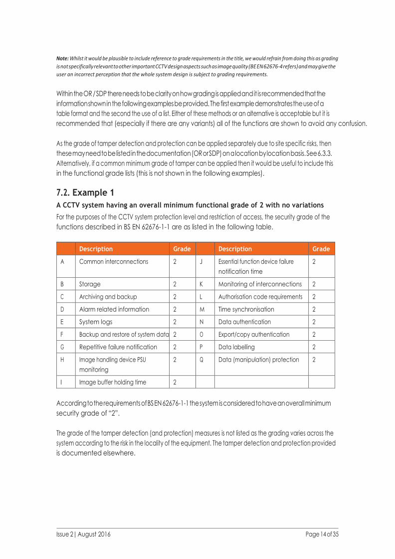
7.2. Example 1
A CCTV system having an overall minimum functional grade of 2 with no variations
For the purposes of the CCTV system protection level and restriction of access, the security grade of the
functions described in BS EN 62676-1-1 are as listed in the following table.
Description Grade Description Grade
A Common interconnections 2 J Essential function device failure
notification time
2
B Storage 2 K Monitoring of interconnections 2
C Archiving and backup 2 L Authorisation code requirements 2
D Alarm related information 2 M Time synchronisation 2
E System logs 2 N Data authentication 2
F Backup and restore of system data 2 O Export/copy authentication 2
G Repetitive failure notification 2 P Data labelling 2
H Image handling device PSU
monitoring
2 Q Data (manipulation) protection 2
I Image buffer holding time 2
According to the requirements of BS EN 62676-1-1 the system is considered to have an overall minimum
security grade of “2”.
The grade of the tamper detection (and protection) measures is not listed as the grading varies across the
system according to the risk in the locality of the equipment. The tamper detection and protection provided
is documented elsewhere.

Issue 2| August 2016 Page 15 of 35
7.3. Example 2
A CCTV system having an overall minimum functional grade of 2 but where some functions
have a different grade
For the purposes of the CCTV system protection level and restriction of access, the security grade of the
functions described in BS EN 62676-1-1 are as listed in the following table.
a) common interconnections Grade “2”
b) storage Grade “3”
c) archiving and backup Grade “2”
d) alarm related information Grade “2”
e) system logs Grade “2”
f) backup and restore of system data Grade “2”
g) repetitive failure notification Grade “2”
h) image handling device PSU monitoring Grade “2”
i) image buffer holding time Grade “2”
j) essential function device failure notification time Grade “2”
k) monitoring of interconnections Grade “2”
l) authorisation code requirements Grade “2”
m) time synchronisation Grade “2”
n) data authentication Grade “2”
o) export/copy authentication Grade “2”
p) data labelling Grade “2”
q) data (manipulation) protection Grade “4”
According to the requirements of BS EN 62676-1-1 the system is considered to have an overall security
grade of “2”.
The grade of the tamper detection (and protection) measures is not listed as the grading varies across the
system according to the risk in the locality of the equipment. The tamper detection and protection provided
is documented elsewhere.
Note: For the purposes of clarity this may be recorded as “Overall System Grade 2 (with variances as recorded)”.
Issue 2| August 2016 Page 16 of 35
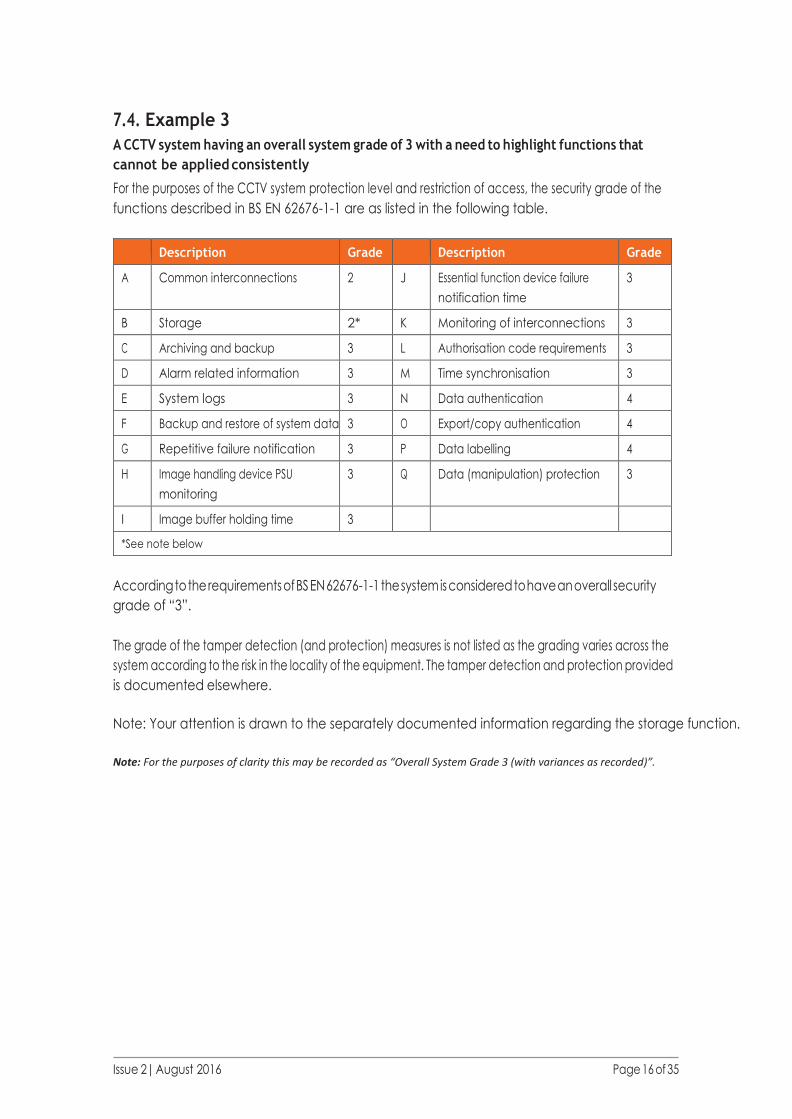
7.4. Example 3
A CCTV system having an overall system grade of 3 with a need to highlight functions that
cannot be applied consistently
For the purposes of the CCTV system protection level and restriction of access, the security grade of the
functions described in BS EN 62676-1-1 are as listed in the following table.
Description Grade Description Grade
A Common interconnections 2 J Essential function device failure
notification time
3
B Storage 2* K Monitoring of interconnections 3
C Archiving and backup 3 L Authorisation code requirements 3
D Alarm related information 3 M Time synchronisation 3
E System logs 3 N Data authentication 4
F Backup and restore of system data 3 O Export/copy authentication 4
G Repetitive failure notification 3 P Data labelling 4
H Image handling device PSU
monitoring
3 Q Data (manipulation) protection 3
I Image buffer holding time 3
*See note below
According to the requirements of BS EN 62676-1-1 the system is considered to have an overall security
grade of “3”.
The grade of the tamper detection (and protection) measures is not listed as the grading varies across the
system according to the risk in the locality of the equipment. The tamper detection and protection provided
is documented elsewhere.
Note: Your attention is drawn to the separately documented information regarding the storage function.
Note: For the purposes of clarity this may be recorded as “Overall System Grade 3 (with variances as recorded)”.

Issue 2| August 2016 Page 17 of 35
8. Summary of the Graded Functions Key:
Graded
Function
Relevant Clauses
and Tables of
BS EN 62676-1-1
Comments CR G1 G2 G3 G4
Name of the
function
Where to find the
graded requirements
Commentary CR = Clause has additional requirements that are not
grade dependent.
G1 = Grade 1, etc.
Y = Applies.
S = Requirements are the same for each grade with
the letter S.
D = Requirements are different for this grade.
= Not Applicable.
Graded Function Relevant Clauses and
Tables of BS EN 62676-1-1
CR G1 G2 G3 G4
Common
interconnections
Clause 6.1.2.2 Y S S
Storage Clause 6.1.3.3 and Table 1 Y D D D
Archiving and backup Clause 6.1.3.4 and Table 2
See also T1.1 and T1.2
Y D D
Alarm related information Clause 6.2.2.3 Y S S
System logs Clause 6.2.2.4 and Table 3 Y D D D
Backup and restore of
system data
Clause 6.3.2.1 S S
Repetitive failure
notification
Clause 6.3.2.2.1 Y S S
Image handling device
PSU monitoring
Clause 6.3.2.2.2 Y Y
Image buffer holding
time
Clause 6.3.2.2.2 Y S S
Essential function device
failure notification time
Clause 6.3.2.2.3 S S
Monitoring of
interconnections
Clause 6.3.2.2.4 and Table 4 D D
Tamper detection Clause 6.3.2.3.1 and Table 5.
Also Clause 6.3.2.3.2
D D D
Authorisation code
requirements
Clause 6.3.2.4 and Table 7 Y D D D D
Time synchronisation Clause 6.3.2.5 S S
Data authentication Clause 6.3.3.2 S S
Export/copy
authentication
Clause 6.3.3.2 S S
Data labelling Clause 6.3.3.1 and Table 11 Y D S S D
Data (manipulation)
protection
Clause 6.3.3.3 Y
Issue 2| August 2016 Page 18 of 35
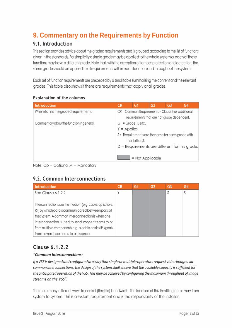
9. Commentary on the Requirements by Function 9.1. Introduction
This section provides advice about the graded requirements and is grouped according to the list of functions
given in the standards. For simplicity a single grade may be applied to the whole system or each of these
functions may have a different grade. Note that, with the exception of tamper protection and detection, the
same grade should be applied to all requirements within each function and throughout the system.
Each set of function requirements are preceded by a small table summarising the content and the relevant
grades. This table also shows if there are requirements that apply at all grades.
Explanation of the columns
Introduction CR G1 G2 G3 G4
Where to find the graded requirements.
Commentary about the function in general.
CR = Common Requirements – Clause has additional
requirements that are not grade dependent.
G1 = Grade 1, etc.
Y = Applies.
S = Requirements are the same for each grade with
the letter S.
D = Requirements are different for this grade.
= Not Applicable
Note: Op = Optional M = Mandatory
9.2. Common Interconnections
Introduction CR G1 G2 G3 G4
See Clause 6.1.2.2
Interconnections are the medium (e.g. cable, optic fibre,
RF) by which data is communicated between parts of
the system. A common interconnection is when one
interconnection is used to send image streams to or
from multiple components e.g. a cable carries IP signals
from several cameras to a recorder.
Y S S
Clause 6.1.2.2
“Common Interconnections:
If a VSS is designed and configured in a way that single or multiple operators request video images via
common interconnections, the design of the system shall ensure that the available capacity is sufficient for
the anticipated operation of the VSS. This may be achieved by configuring the maximum throughput of image
streams on the VSS”.
There are many different ways to control (throttle) bandwidth. The location of this throttling could vary from
system to system. This is a system requirement and is the responsibility of the installer.
Issue 2| August 2016 Page 19 of 35
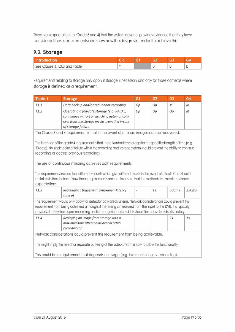
There is an expectation (for Grade 3 and 4) that the system designer provides evidence that they have
considered these requirements and show how the design is intended to achieve this.
9.3. Storage
Introduction CR G1 G2 G3 G4
See Clause 6.1.3.3 and Table 1 Y D D D
Requirements relating to storage only apply if storage is necessary and only for those cameras where
storage is defined as a requirement.
Table 1 Storage G1 G2 G3 G4
T1.1 Data backup and/or redundant recording Op Op M M
T1.2 Operating a fail-safe storage (e.g. RAID 5,
continuous mirror) or switching automatically
over from one storage media to another in case
of storage failure
Op Op Op M
The Grade 3 and 4 requirement is that in the event of a failure images can be recovered.
The intention of the grade 4 requirement is that there is unbroken storage for the specified length of time (e.g.
30 days). No single point of failure within the recording and storage system should prevent the ability to continue
recording or access previous recordings.
The use of continuous mirroring achieves both requirements.
The requirements include four different variants which give different results in the event of a fault. Care should
be taken in the choice of how these requirements are met to ensure that the method also meets customer
expectations.
T1.3 Reacting to a trigger with a maximum latency
time of
- 1s 500ms 250ms
This requirement would only apply for detector activated systems. Network considerations could prevent this
requirement from being achieved although, if the timing is measured from the input to the DVR, it is typically
possibly. If the system is pre-recording and an image is captured this should be considered satisfactory.
T1.4 Replaying an image from storage with a
maximum time after the incident or actual
recording of
- - 2s 1s
Network considerations could prevent this requirement from being achievable.
This might imply the need for separate buffering of the video stream simply to allow this functionality.
This could be a requirement that depends on usage (e.g. live monitoring –v– recording).
Issue 2| August 2016 Page 20 of 35
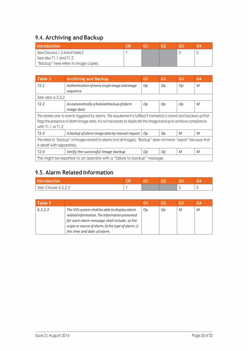
9.4. Archiving and Backup
Introduction CR G1 G2 G3 G4
See Clause 6.1.3.4 and Table 2
See also T1.1 and T1.2
“Backup” here refers to image copies.
Y D D
Table 2 Archiving and Backup G1 G2 G3 G4
T2.1 Authentication of every single image and image
sequence
Op Op Op M
See also 6.3.3.2
T2.2 An automatically scheduled backup of alarm
image data
Op Op Op M
This relates only to events triggered by alarms. This requirement is fulfilled if metadata is stored and backed-up that
flags the presence of alarm image data. It is not necessary to duplicate the image backup to achieve compliance
with T1.1 or T1.2
T2.3 A backup of alarm image data by manual request Op Op M M
This refers to “backup” of images related to alarms (not all images). “Backup” does not mean “export” because that
is dealt with separately.
T2.4 Verify the successful image backup Op Op M M
This might be reported to an operator with a “failure to backup” message.
9.5. Alarm Related Information
Introduction CR G1 G2 G3 G4
See Clause 6.2.2.3 Y S S
Table 5 G1 G2 G3 G4
6.2.2.3 The VSS system shall be able to display alarm
related information. The information presented
for each alarm message shall include: a) the
origin or source of alarm; b) the type of alarm; c)
the time and date of alarm.
Op Op M M

Issue 2| August 2016 Page 21 of 35
9.6. System Logs
Introduction CR G1 G2 G3 G4
See Clause 6.2.2.4 and Table 3
There are no specific requirements about which events
should be logged at grade 1 but if any events are logged
they need to comply with 6.2.2.4.
It is only necessary to log events that can occur on the
system (as per the OR or SDP). For example at Grade
3 it is mandatory to log “Essential function failure and
recovery from failure”. However the related function may
be implemented at Grade 2 not Grade 3 and therefore
the event itself is optional.
Y D D D
Table 3 System Logs G1 G2 G3 G4
T3.1 Alarms Op M M M
T3.2 Tampers Op Op M M
This is a tamper from any part of the system. Only components with tamper monitoring need the
associated logging.
T3.3 Video loss and recovery from video loss Op Op M M
T3.4 Power loss Op M M M
Log of event may be delayed until restore of power. Loss of power to peripheral components might not be
logged except by inference (e.g. video loss).
T3.5 Essential function failure and recovery from
failure
Op Op M M
“Essential functions” are defined as the vital functions of a VSS, which are image capturing, transmission,
recording and / or presentation.
Logging should be provided for all fault conditions that are recognisable at the DVR as defined in the OR
as SDP.
T3.6 Fault messages displayed to the user Op Op Op M
This is a requirement that the contents of fault messages displayed to the user are logged.
T3.7 System reset, start, stop Op M M M
T3.8 Diagnostic actions (health check) Op Op Op M
T3.9 Export, print/ hardcopy incl. the image
source identifier, time range
Op M M M
T3.10 User log in and log out at workstation with
time stamp, successful and denied logins
(local/remote) including reason of denial
(wrong password, unknown user, exceeded
account
Op M M M
T3.11 Changes in authorisation codes Op Op M M
It is recommended that the log record includes the user making the change and the affected user. It
should not log the authorisation code.

Issue 2| August 2016 Page 22 of 35
Table 3 System Logs G1 G2 G3 G4
T3.12 Control of functional cameras Op Op Op M
The log record should show which user had control of the functional camera (but not necessarily what
changes they made) In some cases (e.g. public space monitoring) this might be beneficial at lower
grades.
T3.13 Search for images and replay of images Op Op M M
The log record should show which user searched for images. It is recommended that the search details
are logged (i.e. which cameras, what time period).
T3.14 Manual changes of recording parameters Op Op M M
The log record should show which user changed recording parameters. It is recommended that the
details of the parameters changed are logged including, if possible, the parameter settings.
T3.15 Alarm acknowledge / restore Op Op M M
The log record should show which user acknowledged or restored alarms together with the alarm.
T3.16 System configuration change Op Op M M
The log record should show which user changed the system configuration. It is recommended that the
details of the configuration changed are logged including, if possible, the settings.
T3.17 Date and time set and change with current
time and new time
Op Op M M
The log record should show which user changed the time (or if it is was carried out automatically)
together with the relevant times.
9.7. Backup and Restore of System
Introduction CR G1 G2 G3 G4
See Clause 6.3.2.1
System data are the configurable parameters for
the system. “Backup” here refers to copies of the
configuration.
S S
G1 G2 G3 G4
6.3.2.1 Capable of backup and restore of all system data Op Op M M
This requirement covers backup and restore of all configurable settings throughout the system. As a minimum this
should include DVR. Where possible other components should be included. When equipment is not capable of this a
procedure should be defined to allow for restoration of configuration data.
Issue 2| August 2016 Page 23 of 35
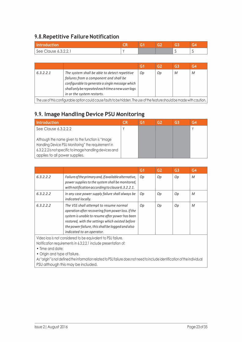
9.8. Repetitive Failure Notification
Introduction CR G1 G2 G3 G4
See Clause 6.3.2.2.1 Y S S
G1 G2 G3 G4
6.3.2.2.1 The system shall be able to detect repetitive
failures from a component and shall be
configurable to generate a single message which
shall only be repeated each time a new user logs
in or the system restarts.
Op Op M M
The use of this configurable option could cause faults to be hidden. The use of the feature should be made with caution.
9.9. Image Handling Device PSU Monitoring
Introduction CR G1 G2 G3 G4
See Clause 6.3.2.2.2
Although the name given to the function is “Image
Handling Device PSU Monitoring” the requirement in
6.3.2.2.2 is not specific to image handling devices and
applies to all power supplies.
Y Y
G1 G2 G3 G4
6.3.2.2.2 Failure of the primary and, if available alternative,
power supplies to the system shall be monitored,
with notification according to clause 6.3.2.2.1.
Op Op Op M
6.3.2.2.2 In any case power supply failure shall always be
indicated locally.
Op Op Op M
6.3.2.2.2 The VSS shall attempt to resume normal
operation after recovering from power loss. If the
system is unable to resume after power has been
restored, with the settings which existed before
the power failure, this shall be logged and also
indicated to an operator.
Op Op Op M
Video loss is not considered to be equivalent to PSU failure.
Notification requirements in 6.3.2.2.1 include presentation of:
• Time and date;
• Origin and type of failure.
As “origin” is not defined the information related to PSU failure does not need to include identification of the individual
PSU although this may be included.

Issue 2| August 2016 Page 24 of 35
9.10. Image Buffer Holding Time
Introduction CR G1 G2 G3 G4
See Clause 6.3.2.2.2 Y S S
G1 G2 G3 G4
6.3.2.2.2 Images shall not be held in a buffer for longer
than 5 seconds without being written into the
storage medium.
Op Op M M
This performance requirement is not one that would have been traditionally met. Installers should check that the
equipment is correctly configured to achieve this.
If the buffer time is greater than 5 seconds but there is redundancy in the VSS such that the images are stored
elsewhere (e.g. in the camera) then this should satisfy this requirement.
9.11. Essential Function Device Failure Notification Time
Introduction CR G1 G2 G3 G4
See Clause 6.3.2.2.3 S S
G1 G2 G3 G4
6.3.2.2.3 The VSS shall manage device failure by
indicating any failure of the essential functions
within 100 s of the failure.
Op Op M M
“Essential functions” are defined as the vital functions of a VSS, which are image capturing, transmission, recording
and/or presentation.

Issue 2| August 2016 Page 25 of 35
9.12. Monitoring of Interconnections
Introduction CR G1 G2 G3 G4
See Clause 6.3.2.2.4 and Table 4.
Interconnections are not limited to those carrying video
but also includes control signals and others.
D D
Table 4 G1 G2 G3 G4
T4.1 Repeatedly verify the interconnection at regular
intervals with a maximum of
- - 30s 10s
T4.2 Try to re-establish a interconnection with
following number of retries before notification
- - 5 2
T4.3 Maximum time permitted before notification to an
operator of an interconnection failure
- - 180s 30s
62676-1-2
T7.1
Maximum permitted duration of device
unavailability
- - 180s 30s
The last two of these requirements refer to the same period of time. Therefore the unavailaibility of an
interconnection must be identified and notified to the operator within the time specified.
It may be difficult to achieve some of these requirements with analogue systems.
Requirement T4.3 The time stated can make allowance for the number of retries. (i.e. once a fault is detected the
retries can be performed before notification is necessary).
9.13. Tamper Detection
Introduction CR G1 G2 G3 G4
See Clause 6.3.2.3.1 and Table 5.
Also Clause 6.3.2.3.2
Although only “detection” is listed as a graded function
tamper “protection” also has graded requirements.
Tamper protection and detection arrangements can vary
from location to location and grading need not be applied
consistently throughout the system.
Tamper requirements may be unnecessary if the camera
is inaccessible.
The tamper protection and detection provided to parts of
the system should be documented in the system design
proposal and/or OR.
Note that although when performing a risk assessment
it may seem unlikely that an attack may be carried out
against parts of the system to overcome the security it
remains a possibility that vandals may simply attack the
CCTV system.
D D D

Issue 2| August 2016 Page 26 of 35
Table 5 G1 G2 G3 G4
T5.1 Video loss Op M M M
62676-1-2
T7.2
Maximum detection time for live signal loss - 8s 4s 2s
T5.2 If an image capturing device with a fixed field of
view no longer includes the entire specified field
of view
Op Op M M
This implies use of video analytics. Care should be taken that the use of video analytics does not result in a large
number of false tamper detections. Consideration should be given to the reaction time (e.g. to permit normal
activities that may affect the image).
T5.3 Deliberately obscuring or blinding of the imaging
device range
Op Op M M
Similar to T5.2
T5.4 The substitution of any video data at image
source, interconnection or handling
Op Op Op M
It is unlikely that this can be achieved using analogue cameras.
T5.5 Significant reduction of the contrast of the image Op Op Op M
G1 G2 G3 G4
6.3.2.3.2 Image capturing devices shall be protected
against tamper
Op Op M M
Installers should refer to manufacturer’s documentation to ensure suitability.
9.14. Authorisation Code Requirements
Introduction CR G1 G2 G3 G4
See Clause 6.3.2.4 and Table 7 Y D D D D
Table 7 G1 G2 G3 G4
T7.1 Minimum Number of possible logical
authorisation keys
- 10,000 100,000 1,000,000
T7.2 Minimum Number of possible physical
authorisation keys
- 3,000 15,000 50,000
At all grades access to functions required to be accessible at level 2, 3 and 4 shall be restricted by means of key,
password, code or similar access-limiting means or device. At Grade 1 this requirement still applies but the number
of possible “keys” is not specified.
Issue 2| August 2016 Page 27 of 35
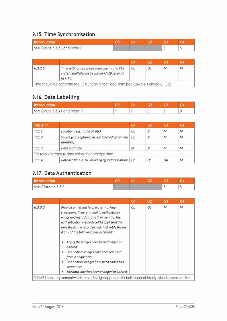
9.15. Time Synchronisation
Introduction CR G1 G2 G3 G4
See Clause 6.3.2.5 and Table 7 S S
G1 G2 G3 G4
6.3.2.5 Time settings of various components of a VSS
system shall always be within +/- 10 seconds
of UTC.
Op Op M M
Time should be accurate to UTC but can reflect local time (see 62676-1-1 clause 6.1.3.8).
9.16. Data Labelling
Introduction CR G1 G2 G3 G4
See Clause 6.3.3.1 and Table 11 Y D S S D
Table 11 G1 G2 G3 G4
T11.1 Location (e.g. name of site) Op M M M
T11.2 Source (e.g. capturing device labelled by camera
number)
Op M M M
T11.3 Date and time M M M M
This refers to capture time rather than storage time.
T11.4 Date and time in UTC including offset for local time Op Op Op M
9.17. Data Authentication
Introduction CR G1 G2 G3 G4
See Clause 6.3.3.2 S S
G1 G2 G3 G4
6.3.3.2 Provide a method (e.g. watermarking,
checksums, fingerprinting) to authenticate
image and meta data and their identity. The
authentication method shall be applied at the
time the data is recorded and shall notify the user
if any of the following has occurred:
• Any of the images have been changed or
altered;
• One or more images have been removed
from a sequence;
• One or more images have been added to a
sequence;
• The data label has been changed or altered.
Op Op M M
Table 2.1 has a requirement which may at first sight appear similar but is applicable only to backup and archive.

Issue 2| August 2016 Page 28 of 35
9.18. Export / Copy Authentication
Introduction CR G1 G2 G3 G4
See Clause 6.3.3.2 S S
G1 G2 G3 G4
6.3.3.2 Provide a method by which the authenticity of
copied and exported data is verified
Op Op M M
9.19. Data (manipulation) protection
Introduction CR G1 G2 G3 G4
See Clause 6.3.3.3 Y
G1 G2 G3 G4
6.3.3.3 Provide a method (e.g. encryption) to prevent
unauthorized persons viewing the images and
other data without permission
Op Op Op M
6.3.3.3 Provide a method to protect the confidentiality of
copied and exported data
Op Op Op M
62676-1-2
Clause 12.1
All data communication outside secured technical
room areas shall be encrypted in the security
grade 4. AES with 128 bit key for symmetric and
RSA with 1 024 bit key shall be provided. Native
encryption shall not be accepted. The VTDs shall
not store any form of passwords in clear text. All
such passwords either in configuration files or a
database shall be encrypted.
A VTD according to this standard shall support
transport level security for the security grade 4.
Op Op Op M
62676-1-2
Clause 12.2
A VTD compliant to this standard shall support
in security grade 4 TLS 1.0 according to the IETF
standard RFC 2246 and TLS 1.1 according to RFC
4346. Optionally the VTD may support TLS 1.2
according to RFC 5246.
Op Op Op M
62676-1-2
Clause 8.3.4
Digest Access Authentication is recommended in
security grade 3 and 4 systems, because of the
higher security provided.
Op Op R* R*
Note: VTD is an abbreviation for Video Transmission Device
*Note this is a recommendation and is therefore not mandatory.
Issue 2| August 2016 Page 29 of 35
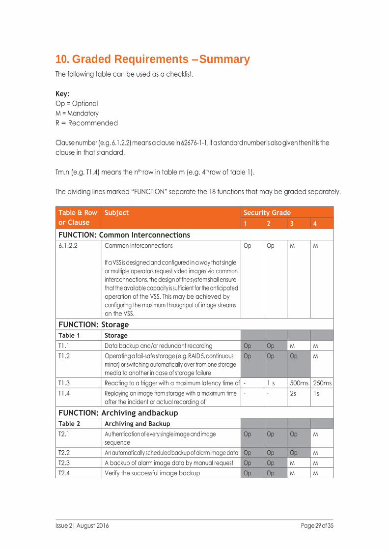
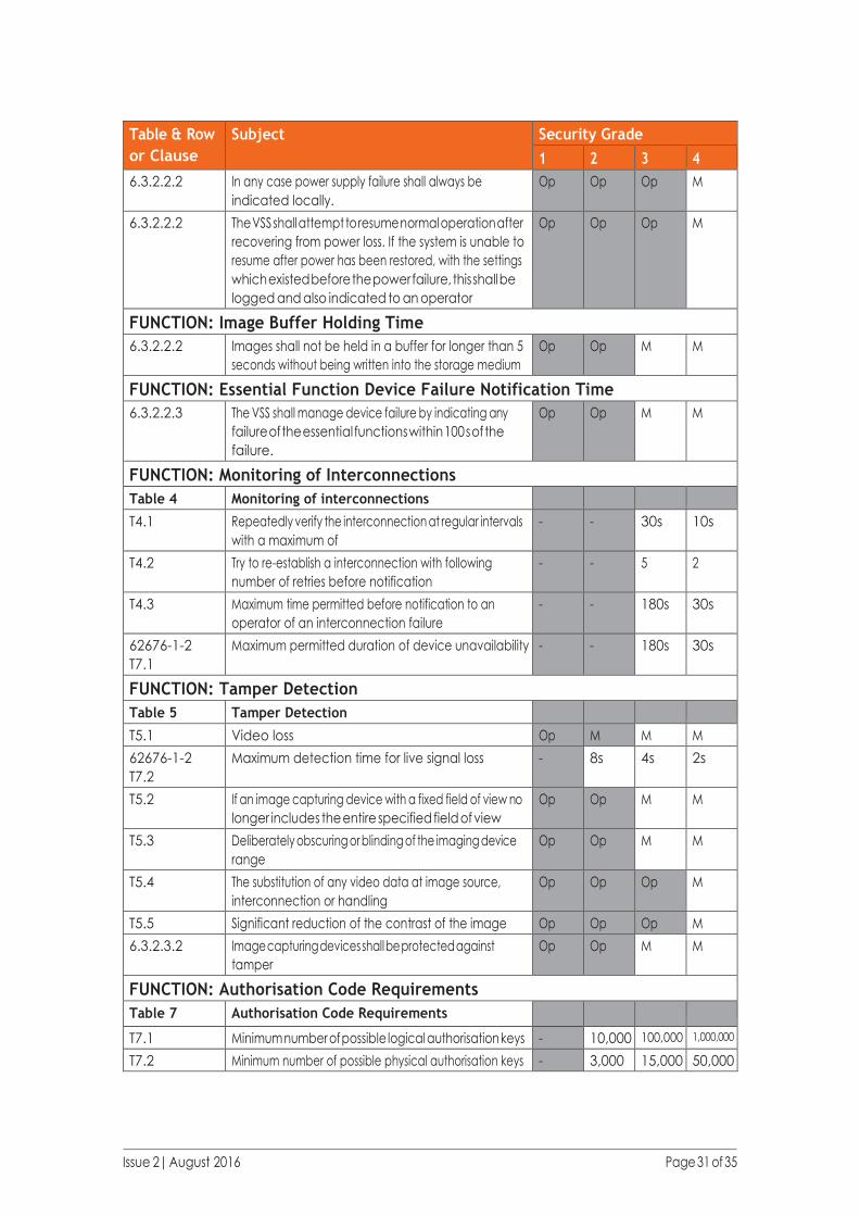
10. Graded Requirements – Summary The following table can be used as a checklist.
Key:
Op = Optional
M = Mandatory
R = Recommended
Clause number (e.g. 6.1.2.2) means a clause in 62676-1-1, if a standard number is also given then it is the
clause in that standard.
Tm.n (e.g. T1.4) means the nth row in table m (e.g. 4th row of table 1).
The dividing lines marked “FUNCTION” separate the 18 functions that may be graded separately.
Table & Row
or Clause
Subject Security Grade
1 2 3 4
FUNCTION: Common Interconnections
6.1.2.2 Common Interconnections
If a VSS is designed and configured in a way that single
or multiple operators request video images via common
interconnections, the design of the system shall ensure
that the available capacity is sufficient for the anticipated
operation of the VSS. This may be achieved by
configuring the maximum throughput of image streams
on the VSS.
Op Op M M
FUNCTION: Storage
Table 1 Storage
T1.1 Data backup and/or redundant recording Op Op M M
T1.2 Operating a fail-safe storage (e.g. RAID 5, continuous
mirror) or switching automatically over from one storage
media to another in case of storage failure
Op Op Op M
T1.3 Reacting to a trigger with a maximum latency time of - 1 s 500ms 250ms
T1.4 Replaying an image from storage with a maximum time
after the incident or actual recording of
- - 2s 1s
FUNCTION: Archiving and backup
Table 2 Archiving and Backup
T2.1 Authentication of every single image and image
sequence
Op Op Op M
T2.2 An automatically scheduled backup of alarm image data Op Op Op M
T2.3 A backup of alarm image data by manual request Op Op M M
T2.4 Verify the successful image backup Op Op M M

Issue 2| August 2016 Page 30 of 35
Table & Row
or Clause
Subject Security Grade
1 2 3 4
FUNCTION: Alarm Related Information
6.2.2.3 The VSS system shall be able to display alarm related
information. The information presented for each alarm
message shall include: a) the origin or source of alarm;
b) the type of alarm; c) the time and date of alarm.
Op Op M M
FUNCTION: System Logs
Table 3 System Logs
T3.1 Alarms Op M M M
T3.2 Tampers Op Op M M
T3.3 Video loss and recovery from video loss Op Op M M
T3.4 Power loss Op M M M
T3.5 Essential function failure and recovery from failure Op Op M M
T3.6 Fault messages displayed to the user Op Op Op M
T3.7 System reset, start, stop Op M M M
T3.8 Diagnostic actions (health check) Op Op Op M
T3.9 Export, print/ hardcopy incl. the image source identifier,
time range
Op M M M
T3.10 User log in and log out at workstation with time stamp,
successful and denied logins (local/remote) including
reason of denial (wrong password, unknown user,
exceeded account
Op M M M
T3.11 Changes in authorisation codes Op Op M M
T3.12 Control of functional cameras Op Op Op M
T3.13 Search for images and replay of images Op Op M M
T3.14 Manual changes of recording parameters Op Op M M
T3.15 Alarm acknowledge / restore Op Op M M
T3.16 System configuration change Op Op M M
T3.17 Date and time set and change with current time and
new time
Op Op M M
FUNCTION: Backup and Restore of System
6.3.2.1 Capable of backup and restore of all system data. Op M M M
FUNCTION: Repetitive Failure Notification
6.3.2.2.1 The system shall be able to detect repetitive failures
from a component and shall be configurable to generate
a single message which shall only be repeated each time
a new user logs in or the system restarts.
Op Op M M
FUNCTION: Image Handling Device PSU Monitoring
6.3.2.2.2 Failure of the primary and, if available alternative,
power supplies to the system shall be monitored, with
notification according to clause 6.3.2.2.1.
Op Op Op M
Issue 2| August 2016 Page 31 of 35
Table & Row
or Clause
Subject Security Grade
1 2 3 4
6.3.2.2.2 In any case power supply failure shall always be
indicated locally.
Op Op Op M
6.3.2.2.2 The VSS shall attempt to resume normal operation after
recovering from power loss. If the system is unable to
resume after power has been restored, with the settings
which existed before the power failure, this shall be
logged and also indicated to an operator
Op Op Op M
FUNCTION: Image Buffer Holding Time
6.3.2.2.2 Images shall not be held in a buffer for longer than 5
seconds without being written into the storage medium
Op Op M M
FUNCTION: Essential Function Device Failure Notification Time
6.3.2.2.3 The VSS shall manage device failure by indicating any
failure of the essential functions within 100 s of the
failure.
Op Op M M
FUNCTION: Monitoring of Interconnections
Table 4 Monitoring of interconnections
T4.1 Repeatedly verify the interconnection at regular intervals
with a maximum of
- - 30s 10s
T4.2 Try to re-establish a interconnection with following
number of retries before notification
- - 5 2
T4.3 Maximum time permitted before notification to an
operator of an interconnection failure
- - 180s 30s
62676-1-2
T7.1
Maximum permitted duration of device unavailability - - 180s 30s
FUNCTION: Tamper Detection
Table 5 Tamper Detection
T5.1 Video loss Op M M M
62676-1-2
T7.2
Maximum detection time for live signal loss - 8s 4s 2s
T5.2 If an image capturing device with a fixed field of view no
longer includes the entire specified field of view
Op Op M M
T5.3 Deliberately obscuring or blinding of the imaging device
range
Op Op M M
T5.4 The substitution of any video data at image source,
interconnection or handling
Op Op Op M
T5.5 Significant reduction of the contrast of the image Op Op Op M
6.3.2.3.2 Image capturing devices shall be protected against
tamper
Op Op M M
FUNCTION: Authorisation Code Requirements
Table 7 Authorisation Code Requirements
T7.1 Minimum number of possible logical authorisation keys - 10,000 100,000 1,000,000
T7.2 Minimum number of possible physical authorisation keys - 3,000 15,000 50,000
Issue 2| August 2016 Page 32 of 35
Table & Row
or Clause
Subject Security Grade
1 2 3 4
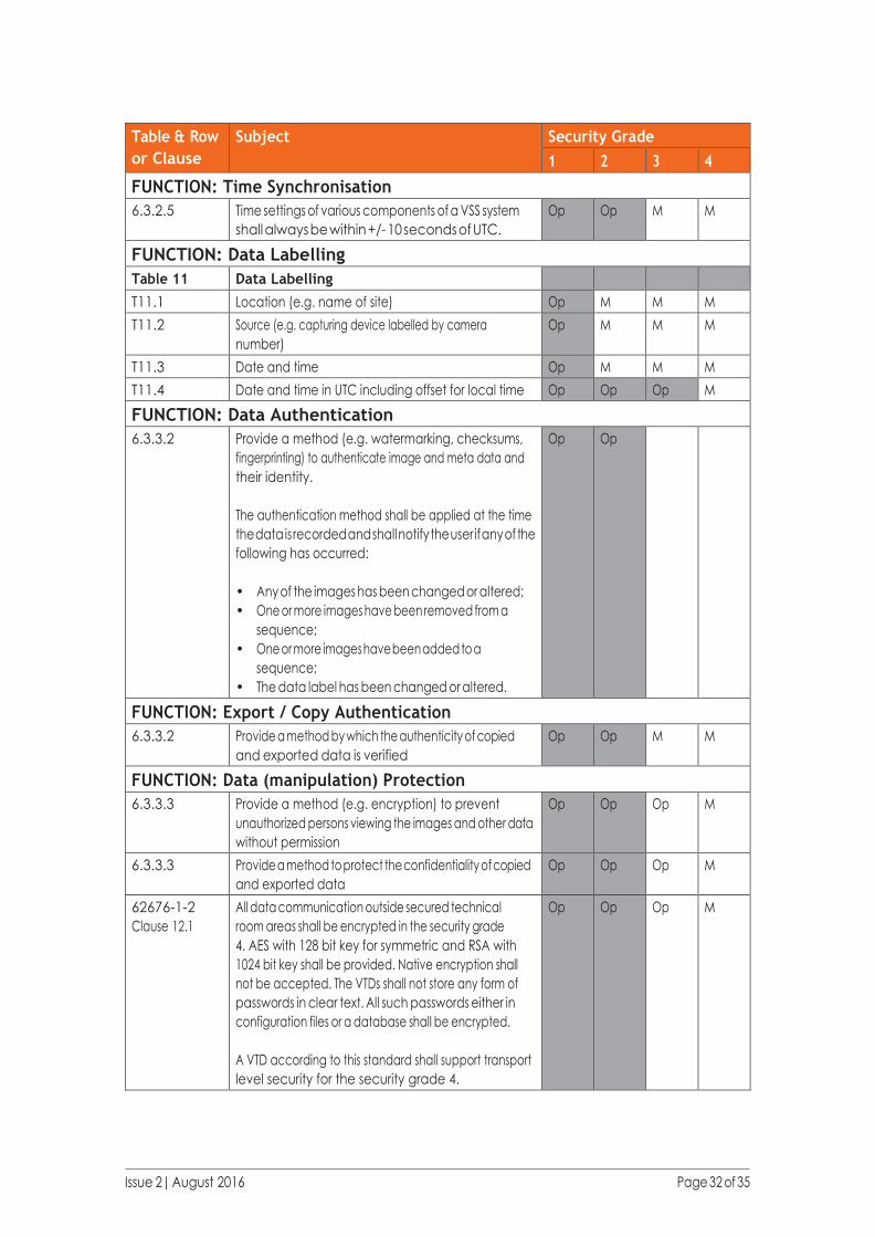
FUNCTION: Time Synchronisation
6.3.2.5 Time settings of various components of a VSS system
shall always be within +/- 10 seconds of UTC.
Op Op M M
FUNCTION: Data Labelling
Table 11 Data Labelling
T11.1 Location (e.g. name of site) Op M M M
T11.2 Source (e.g. capturing device labelled by camera
number)
Op M M M
T11.3 Date and time Op M M M
T11.4 Date and time in UTC including offset for local time Op Op Op M
FUNCTION: Data Authentication
6.3.3.2 Provide a method (e.g. watermarking, checksums,
fingerprinting) to authenticate image and meta data and
their identity.
The authentication method shall be applied at the time
the data is recorded and shall notify the user if any of the
following has occurred:
• Any of the images has been changed or altered;
• One or more images have been removed from a
sequence;
• One or more images have been added to a
sequence;
• The data label has been changed or altered.
Op Op
FUNCTION: Export / Copy Authentication
6.3.3.2 Provide a method by which the authenticity of copied
and exported data is verified
Op Op M M
FUNCTION: Data (manipulation) Protection
6.3.3.3 Provide a method (e.g. encryption) to prevent
unauthorized persons viewing the images and other data
without permission
Op Op Op M
6.3.3.3 Provide a method to protect the confidentiality of copied
and exported data
Op Op Op M
62676-1-2
Clause 12.1
All data communication outside secured technical
room areas shall be encrypted in the security grade
4. AES with 128 bit key for symmetric and RSA with
1024 bit key shall be provided. Native encryption shall
not be accepted. The VTDs shall not store any form of
passwords in clear text. All such passwords either in
configuration files or a database shall be encrypted.
A VTD according to this standard shall support transport
level security for the security grade 4.
Op Op Op M

Issue 2| August 2016 Page 33 of 35
Table & Row
or Clause
Subject Security Grade
1 2 3 4
62676-1-2
Clause 12.2
A VTD compliant to this standard shall support in
security grade 4 TLS 1.0 according to the IETF standard
RFC 2246 and TLS 1.1 according to RFC 4346. Optionally
the VTD may support TLS 1.2 according to RFC 5246.
Op Op Op M
62676-1-2
Clause 8.3.4
Digest Access Authentication is recommended in
security grade 3 and 4 systems, because of the higher
security provided.
Op Op R R
11. Guidance for Manufacturers 11.1 Introduction
As mentioned in the Introduction to this document, the grading of CCTV is not the same as the grading
of Intruder & Hold-up Alarm Systems in which there are a number of component standards. Using a
component standard means that a manufacturer can test a product and ensure that it meets a particular
specification and therefore grade. The manufacturer can then promote the product as being suitable for an
installation that requires that grade.
From the point of view of a specifier, system integrator or installer the advantage of being able to buy a
product with a known grade is obvious as it saves a lot of effort assessing the product capability. Whilst the
grading is carried out by the designer or installer, there is a requirement for the component to be capable of
meeting the functionality specified within the standard. Though there is no obligation on the manufacturer
to declare a “grade” of component, it may be beneficial for manufacturers to indicate grade compatibility
(this may vary as a result of configuration changes or options) as it may aid use of their product in the
market place.
In summary, we can say that indicating the suitability of a product for use to meet a certain grade
requirement is recommended but that the task of determining the grade of a product is not easy.
11.2 System v Component
The major difficulty for assessing the grade of a product is that the BS EN 62676 standards are primarily
based on the system. This means that to meet the graded requirement it is necessary to check that the
components of the system achieve the requirements when used in combination. If all of the components
in a system are made by a single manufacturer then this may be easier to assess, but in other cases this
may be less straightforward. Caution may be required if single products within a system are upgraded (e.g.
by a software update) because this could cause a function to work differently or not work at all or cause
compatibility issues with other products.
Even where a manufacturer determines that their product can be installed, for example, to achieve the
grade 3 requirements, this does not mean that it will meet these requirements when installed. For example,
a product may have a facility to ensure monitoring of interconnections (see 9.12), but if it is connected to
another product without this feature the system, as a whole, will not meet the requirement for grade 3.

Issue 2| August 2016 Page 34 of 35
There is also the possibility that a manufacturer may make a product which can be configured to meet the
graded requirements or not. In this instance the product documentation can make clear which configuration
would be necessary.
The best a manufacturer can do is state the highest grade that a component could meet. There are some
requirements that a product may not be able to meet at a higher grade and this will clearly limit that
product no matter what the remainder of the system can do.
11.3 Graded Functions
Some graded features may not be relevant for certain products and this should be highlighted.
It is important to note that it is not just the overall grade of a component that is important. A CCTV
system may not require all the features of a product or, as explained in section 6, the part of the system
may be graded differently. This means that even if a product does not meet every aspect of the graded
requirements it may still be suitable.
A customer might need to break all the functional requirements down to the smallest element in order to
assess suitability but this would mean providing a large amount of complicated information. The optimum
approach could be to use a method similar to that shown in Section 7. Manufacturers can use the
information in Section 9 to assist with determining compliance.
The following is an example of how the manufacturer might present the information.
This product is suitable for use in a BS EN 62676-1 installation to a maximum overall grade of 2
Where a CCTV system installation does not require all functions to meet the graded requirement, the
following table may help to assess the suitability. Note that the equipment must be configured and installed
as specified elsewhere in this documentation to ensure compliance.
Description Grade Description Grade
A Common interconnections 2 J Essential function device failure
notification time
4
B Storage 2 K Monitoring of interconnections 4
C Archiving and backup 2 L Authorisation code requirements N/A
D Alarm related information 2 M Time synchronisation 2
E System logs N/A N Data authentication 2
F Backup and restore of system data 2 O Export/copy authentication N/A
G Repetitive failure notification 2 P Data labelling 2
H Image handling device PSU
monitoring
2 Q Data (manipulation) protection 2
I Image buffer holding time 3
Issue 2| August 2016 Page 35 of 35
11.4 Tamper Protection
As noted in 6.3.3, tamper protection and detection is treated differently and can be dealt with on an
individual component location basis. It can also be that this protection can be provided by ancillary
equipment. For example, a camera could be housed in a separately purchased protective housing.
11.5 Summary
Expecting an installer or integrator to analyse the specification of every product used to form a system is
somewhat impractical but it is also difficult for a manufacturer to guarantee the suitability of a product with
regard to graded requirements given the diverse possibilities for an installation.
Assessment by the manufacturer of the potential grading of their products (or at a minimum a statement
about the best possible grade that could be achieved) and the presentation of this in a standard format, such
as that shown above, will assist all parties in meeting the operational requirements of the CCTV system.

This document was created by the CCTV Section of the British Security Industry Association (BSIA).
The British Security Industry Association is the trade association for the private security industry in the UK. Our
members provide over 70% of UK security products and services and adhere to strict quality standards.
CCTV has had a profound impact on crime prevention and detection. The UK leads the way in the application of
CCTV and its use is wide-ranging, encompassing facial-recognition technology, remote video monitoring, video
smoke detection, mobile systems and Automatic Number Plate Recognition as well as many other functions.
In order to provide guidance and simplification in the complex area of CCTV, the BSIA is very active in the European
& International standards arena’s and also develops its own guides and codes of practice where currently
standards do not exist.
The CCTV section encourages debate on new developments and concerns, such as digital video evidence and
facilitating communication protocols between different manufacturers’ products. In doing so it seeks to ensure
that all stakeholder interests are represented including: security companies, users, the Police, inspectorates and
insurers. The section also works with Government on these issues.
CCTV must be operated responsibly in order to respect citizens’ rights and maintain public confidence. Laws
such as the Data Protection Act have an important role to play in achieving this. BSIA CCTV companies drive best
practice in this area and can provide advice on how CCTV users can adhere to the relevant legislation.
BSIA membership will raise your company profile and ensure that your business is at the heart of influencing the
future of the security industry. You will become part of a unique group of high quality and professional companies
which are well-respected and well-represented to government, end users, specifiers, standards and legislative
bodies. For more information contact the BSIA.
BSIA Ltd
Kirkham House
John Comyn Drive
Worcester
WR3 7NS
t: 0845 389 3889 e: [email protected]
www.bsia.co.uk @thebsia