graded unit stage 1
TRANSCRIPT

Graded Unit 2Stage 1
Dylan Fitzsimmons30050607
E3HNDMECENDV1235

1
ContentsDesign Brief page2
Specification page2
Budget page2
Research page2
Schedule page2
Gorlov Helical Turbine page2
Advantages page3
Disadvantages page4
Concept Sketches page4
Materials page6
Wood page6
Metal page6
Plastic page6
Components page7
Calculations page7
Symbol Prefix page7
Power calculations page7
Torque calculation page7
Tip speed ratio calculation page7
Worked Example page8
Design Matrix page9
Gorlov Helical page10
Horizontal-axis page10
Darrieus page10
Savionious page10
References page11

2
Appendices page12
Design Brief1.1 Skye LTD has been chosen by Eco-league to design and construct an affordable wind turbine
that produces enough energy to power small household appliances. The ambition of the client is that the wind turbine is commissioned into mass production for commercial use, should it meet the specification. The target market for this product is young people between the ages of 18-25 who are environmentally conscious. Skye LTD plans on achieving this target after conducting thorough research into 4 different types of turbine: Savonius, Horizontal-Axis Towered, Gorlov Helical, and Darrieus. The appropriate model to base the design will be chosen on multiple factors such as optimal operating height, consequences of balance on structure which include pulsating effect, and manufacturing capability. The project will be completed on 26/05/2016.
Specification Height 1.5mBlade diameter 1mPower 20 WattsVoltage 12VOperating wind speed 15mph
Budget1.2 £150 has been allocated to the design team for purchasing materials. Labour costs at £45 p/h.
ResearchGorlov Helical Dylan FitzsimmonsSavonius Charles ThomsonDarrieus Chris WalkerStandard Horizontal Towered Kieran Johnstone
Schedule1.3 All planning was done in advance through the aid of Gantt charts – which were revised –
(appendix 1, 2 and 3), and a mind map used by the research group (appendix 4).
1.4 Minutes were taken at each meeting with the client (appendix 5, 6, 7, 8, 9, 10, 11).
Gorlov Helical Turbine1.5 Based on the product specification by Eco-league, the vertical-axis design would be the most
pertinent due to its optimal operating height being lower than the horizontal-axis design – which achieves better results at higher altitudes. However, common vertical-axis wind turbines have other issues that are less beneficial such as torque ripple; common in the standard ‘egg beater’ design of the Darrieus. This is due to the difference in wind speeds on each blade at the same time; known as wind shear, which results in a contrast of forces – creating a pulsating effect. This

3
is where the addition of a 3rd blade and the change in shape to a more ‘helical’ structure would completely eliminate this problem by equally distributing the load.
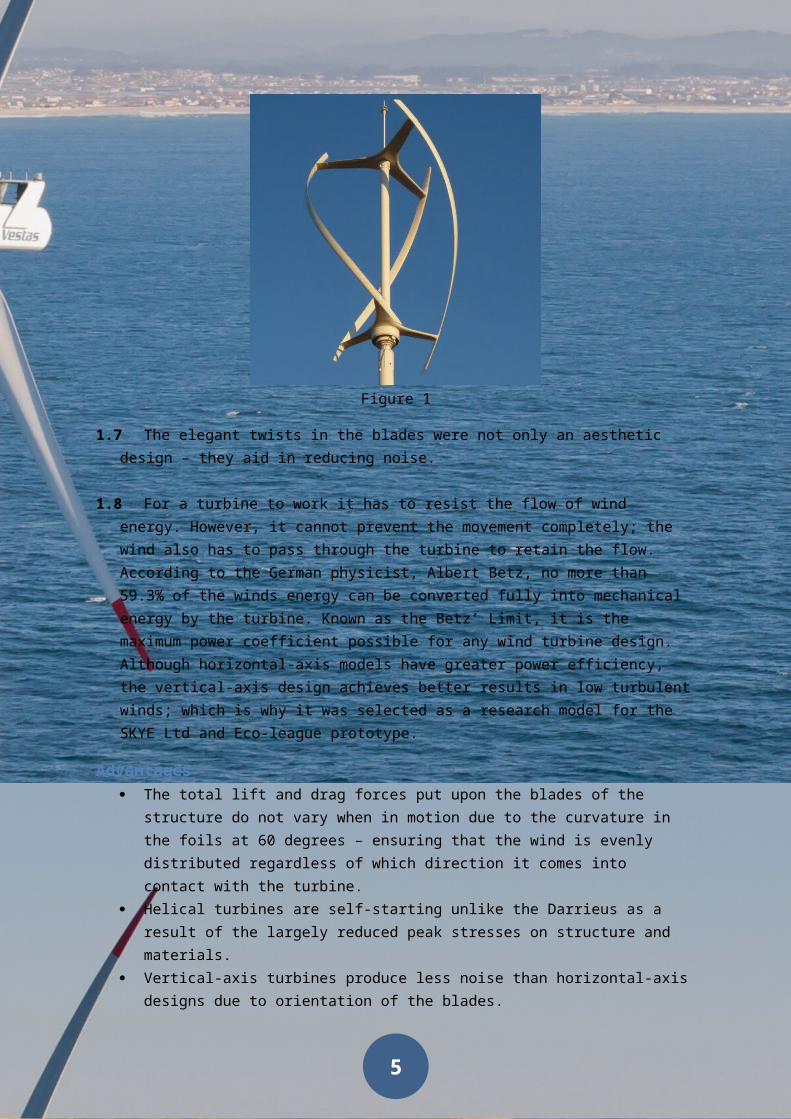
1.6 First developed in the 1990s by Professor Alexander Gorlov, the Gorlov Helical Turbine (GHT) was not intended as a wind turbine; in fact it was specifically designed for hydroelectric purposes. Taking inspiration from the design, inventors started to develop vertical-axis wind turbines using the helical blades due to the additional benefits and reduction of negative impacts from the standard Darrieus model. One such example is the QuietRevolution qr5 (figure1).
Figure 1
1.7 The elegant twists in the blades were not only an aesthetic design – they aid in reducing noise.
1.8 For a turbine to work it has to resist the flow of wind energy. However, it cannot prevent the movement completely; the wind also has to pass through the turbine to retain the flow. According to the German physicist, Albert Betz, no more than 59.3% of the winds energy can be converted fully into mechanical energy by the turbine. Known as the Betz’ Limit, it is the maximum power coefficient possible for any wind turbine design. Although horizontal-axis models have greater power efficiency, the vertical-axis design achieves better results in low turbulent winds; which is why it was selected as a research model for the SKYE Ltd and Eco-league prototype.
Advantages The total lift and drag forces put upon the blades of the structure do not vary when in
motion due to the curvature in the foils at 60 degrees – ensuring that the wind is evenly distributed regardless of which direction it comes into contact with the turbine.
Helical turbines are self-starting unlike the Darrieus as a result of the largely reduced peak stresses on structure and materials.
Vertical-axis turbines produce less noise than horizontal-axis designs due to orientation of the blades.
4
The helical blade design is almost guaranteed to eliminate or drastically reduce torque ripple.
The flow is maintained at a perpendicular angle to the axis of all vertical wind turbines; hence why they always spin in the same direction.
The vertical-axis design does not require as great a wind speed as the horizontal-axis model, the outcome of which makes them more practical for installations on the ground.
As a consequence of its height, the cost of installation and maintenance related with horizontal-axis turbines can be expensive; whereas the helical model, being closer to the ground in a much smaller design, results in the costs being reduced.
Disadvantages The vertical-axis design proves to be less efficient than the horizontal model, a repercussion
of the additional drag created within its foil rotation. Inappropriate for areas with greater wind speeds as they best operate in more mild
conditions.
Concept Sketches
Figure 2
1.9 The above drawing (figure 2) represents a possible design for a vertical-axis wind turbine with helical blades. The above design is common with small turbines situated on top of buildings; the blades are attached to the base and roof instead of the shaft. When in motion, the blades and two discs on top and on bottom protect the shaft from the weather, making it more durable than other designs.
5
Figure 3
1.10 Figure 3 uses the same design as QuietRevolution with the qr5 model. Unlike figure 2, figure 3 is more common in larger vertical-axis designs; mainly found on top of buildings or mounted on large poles in business parks. The design is praised for its efficiency in both low and high speed winds.
Figure 4
1.11 The above design (figure 4) differs from figure 2 and 3 as its foils cover a much greater area, displacing a larger amount of wind. The blades are shaped so that the wind does not pass through them, but passes over them after it makes contact. The result of this design is lower efficiency at higher speeds, which is why they are usually located on the ground in parks.

6
MaterialsWood Properties
Ash Open-grained, tough, flexible, lightBeech Close-grained, tough, hard, easily warpedElm Interlocking grain, tough, resists splitting,
durable
1.12 Although some types of wood such as ash would be ideal for the blades of the turbine, the time constraints are too much and it would not be possible to complete the project by the deadline. However, such materials may be considered for use during construction of the base or stalk of the turbine.
Metal PropertiesCast iron (ferrous) Hard, brittle, corrodes by rustingStainless steel (ferrous) Hard, tough, resistant to water and corrosionAluminium Soft, ductile, light, high strength to weight ratioCopper Ductile, malleable, corrosion resistance
1.13 Although some types of metal such as aluminium may be suitable for the blades of the turbine, the manufacturing capability is not available as the material has to be melted into a mould and the project has no access to a furnace or anyone qualified to use one. Also the mould would be too much of a time constraint. However, there may be a use for metals such as cast iron for the base of the turbine which would help with stability due to its weight and inflexibility.
Plastic PropertiesAcrylic Stiff and brittleAcrylonitrile butadiene styrene (ABS) Tough, strong, hard, durable, resistant to
chemicals, lightweight,High-density PVC foam Tough, stiff, hard, resistant to chemicals,
lightweightPolyvinyl sheet (PVC) Tough, stiff, strongPolystyrene sheet Stiff, brittle, hard, lightweight, transparent and
high resistance to water corrosion
1.14 Since thermoplastics are soft when heated and hard when cooled, these plastics would be ideal for the blades of the turbine. Acrylic can be ruled out as it’s too brittle and may shear under greater wind speeds; standard PVC and polystyrene sheet are both suitable although there are better options. Acrylonitrile butadiene styrene (ABS) and high-density PVC foam are the most viable candidates for the blades. ABS is the best option for strong and durable blades; however the material is 25% more expensive than the high-density PVC – which may possibly take it out of consideration.

7
ComponentsPart Price
Rotational shaft – 50x50mm by 1200mm steel £20-30Brakes – 15mm by 60mm cast iron £10DC 12V electric motor 250rpm £25-30Blades – (3) 1000mm by 600mm PVC £15-20Base – (6) 40x40mm by 800mm cast iron £20-30Bicycle bearings £3-512V battery pack for storage £20-30
Total £113-155
1.15 Project potentially coming in over-budget. Some parts would need to be second hand.
CalculationsVariable Symbol UnitsPower P WattsDensity ρ KG /m3
Area A m2
velocity v ms
PowerCoeffient Cp ¿Torque τ Nm
Angular velocity ω rad / sTip speed ratio λ ¿
1.16 To calculate the approximate amount of power achieved by the turbine the following equation is used,
P=12× ρ× A ×v3×Cp
1.17 Theoretically, the maximum coefficient of power as explained previously is 0.593. However, due to losses by drag forces and mechanical friction, a realistic value would be around 0.3.
1.18 The power of the turbine can also be calculated using the value of torque being produced and the rotational speed of the motor,
P=τ×ω
1.19 For turbines aided by drag forces; the following equation is used to calculate torque,
τ=12×ρ×v2× A×r
1.20 Finally, the equation for tip speed ratio is given as,

8
λ=ω×rv
Worked example1.21 The following calculations are relevant for concept drawing 3 (figure 4 on page 5).
1.22 For a turbine with a blade diameter of 0.6m and a height of 1m; the area of the blade would be,
A=D×h
A=0.6×1
A=0.6m2
1.23 Using this value for the area of the blade and using the density of air at 1.225KG /m3, the
operating wind speed at 15mph(6.7 ms
), and a power coefficient value of 0.3; we are able to
calculate power,
P=12× ρ× A ×v3×Cp
P=12×1.225×0.6×6.73×0.3
P=33.2Watts
1.24 Using the value for v as 6.7 ms and the radius of the blade as 0.3m; it is possible to calculate
the angular velocity that is necessary for RPM. Shown as,
ω= vr
ω=6.70.3
ω=22.3 rad /s
RPM=22.3×602π
RPM=212.95rev /m
1.25 Ultimately, using the value given for the angular velocity, the speed of wind and the radius of the blade; it is possible to calculate the tip speed ratio,
λ=ω×rv

9
λ=22.3×0.36.7
λ=0.9985
1.26 The final answer reached is the radio of speed from the base of the blade to its tip. Realistically, turbine concept 3 (figure 4) would have a ratio in the range of 2-3.
Design Matrix1.27 The chosen factors of the design matrix are key components that are needed to ensure that
the best possible researched design was chosen for the prototype. Each is ranked by importance as to prioritise them above lesser valued factors. For example; aesthetics (ranked 7 for importance) multiplied by the score given to Gorlov Helical (10) = 70, followed by the rest of the factors then totalled up to give a final value.
Individual matrixFactor Importance Gorlov Helical Savionious Darrieus Horizontal-axisCost 8 3 7 6 7Effi ciency 8 7 8 6 6Safety 10 7 7 7 7Manufacturing Capabiltiy 9 3 8 7 3Durability 8 6 7 6 5Life Span 6 6 6 6 5Aesthetics 7 10 7 7 9
Total 331 404 362 334
Figure 5
1.28 The group matrix is the average of the values given by each member of the research team.
Group matrixFactor Importance Gorlov Helical Savionious Darrieus Horizontal-axisCost 8 4 7 7 7Effi ciency 8 6 8 6 5Safety 10 7 7 6 7Manufacturing Capabiltiy 9 3 8 7 4Durability 8 6 7 6 6Life Span 6 6 6 6 6Aesthetics 7 8 7 7 8
Total 306 387 354 344 Figure 6
1.29 It is important that a group matrix is conducted as it is the most fair and logical way to decide as a research team what the design should be for the prototype; effectively eliminating the bias that can be present in each individuals’ evaluation.

10
Matrix comparison chart
Gorlov H
elical
Savionious
Darrieu
s
Horizontal
-axis
050
100150200250300350400450
331404
362334306
387354
344
Individual matrixGroup matrix
Figure 7
1.30 In accordance to the design matrix, Savonius would be the most suitable option for the prototype; followed by the Darrieus model. The least favourable would be the Gorlov Helical design; a result of its low scores.
1.31 Although the Helical turbine scores high in areas such as aesthetics and safety, it lacks in other crucial departments. One such department is cost. The budget of the project is not flexible, which would unquestionably rule it out for consideration. Secondly, manufacturing capability is low. The team do not have enough time to design and construct the helical model, they also do not possess the necessary skills or essential tools for the build; ensuring its inadequacy.
1.32 The horizontal-axis design’s shortfall is its manufacturing capability, although a proven turbine; it is not possible for the SKYE Ltd design team to construct. Furthermore, the model is less efficient than the other options.
1.33 Unlike the horizontal-axis model, the Darrieus is a capable choice of design due to its moderate scores in essential areas: cost, efficiency, safety, manufacturing capability, durability.
1.34 Ultimately, the Savonius scores highest in the sections which other models fail to do so. The model is the most efficient design for the given specification by Eco-League, which is exactly what the client is looking for in the final product. The Savonius is able to deliver this at the same cost as the Darrieus, whilst improving on safety. The design also maintains a highly durable final product, despite being the most straightforward to manufacture in comparison with other alternatives. Overall, the Savonius scores above its competitors in almost every category when amalgamated; securing its position as the most pertinent design for the prototype.

11
ReferencesMeyers, C. (2013). Types of Wind Turbines. [online] Centurionenergy.net. Available at: http://centurionenergy.net/types-of-wind-turbines [Accessed 8 Jan. 2016].
Wind-works.org. (2013). WIND-WORKS: Gorlov Helical Wind Turbine. [online] Available at: http://www.wind-works.org/cms/index.php?id=64&tx_ttnews%5Btt_news%5D=2359&cHash=527245fde9795b02652c95628a82fa50 [Accessed 7 Jan. 2016].
Reuk.co.uk. (2010). Betz Limit. [online] Available at: http://www.reuk.co.uk/Betz-Limit.htm [Accessed 11 Jan. 2016].
Bbc.co.uk. (2014). BBC - GCSE Bitesize: Timber. [online] Available at: http://www.bbc.co.uk/schools/gcsebitesize/design/resistantmaterials/materialsmaterialsrev1.shtml [Accessed 12 Jan. 2016].
Bbc.co.uk. (2014). BBC - GCSE Bitesize: Metals. [online] Available at: http://www.bbc.co.uk/schools/gcsebitesize/design/resistantmaterials/materialsmaterialsrev2.shtml [Accessed 12 Jan. 2016].
Bbc.co.uk. (2014). BBC - GCSE Bitesize: Plastics. [online] Available at: http://www.bbc.co.uk/schools/gcsebitesize/design/resistantmaterials/materialsmaterialsrev3.shtml [Accessed 12 Jan. 2016].
Medicine, H. and Intermediate, P. (n.d.). Hollow Bar Steel Solid. [online] Made-in-china.com. Available at: http://www.made-in-china.com/products-search/hot-china-products/Hollow_Bar_Steel_Solid.html [Accessed 9 Jan. 2016].
Sheetplastics.co.uk. (n.d.). Sheet Plastic | Acrylic Sheets | Plastic Sheet Suppliers. [online] Available at: https://www.sheetplastics.co.uk/?infinity=ict2~net~gaw~ar~46890961291~kw~custom%20perspex%20sheet~mt~b~cmp~TC%3A%20Perspex%20%2715%20%28Search%29~ag~custom%20perspex%20%28broad%2Fm%29&gclid=CN_Lk9eIgssCFQQGwwodbvMExg [Accessed 9 Jan. 2016].
Halfords.com. (n.d.). Brake Pads & Wear Sensors | Front Brake Pads | Car Brake Pads | Halfords. [online] Available at: http://www.halfords.com/motoring/car-parts/brakes/brake-pads-wear-sensors [Accessed 9 Jan. 2016].
Wind & wet. (2016). Wind power calculator. [online] Available at: http://www.windandwet.com/windturbine/power_calc/index.php [Accessed 11 Jan. 2016].
Piggott, H. (2011). Wind power workshop. 1st ed. Machynlleth: Centre for Alternative Technology, pp.47-55.

12
Appendices
Gantt chart 1
Gantt chart 2

13
Gantt chart 3

14
Mind map